background and objectives - lawrence livermore national ...€¦ · web viewif the offeror...
TRANSCRIPT
DRAFTLLNS-PROP-XXXXXX-DRAFT
Commodity Technology Systems 2 (CTS-2)
Draft Statement of WorkRFP BXXXXXXAttachment 2
April 21, 2020
LLNL-TR-800120
DRAFTCTS-2 Statement of Work
Requirements Definitions & Other Terms
Particular sections of this draft Statement of Work (SOW) have priority designations, which are defined as follows and will be considered as part of the proposal evaluation and selection process.
a) Mandatory Requirements designated as MR—Mandatory Requirements in this draft SOW are performance features that are essential to the Tri-Laboratories’ requirements, and an Offeror must satisfactorily propose all Mandatory Requirements in order to have its proposal considered responsive.
b) Target Requirements designated TR-1, TR-2, or TR-3 in this draft SOW are features, components, performance characteristics, or other properties that are important to the Tri-Laboratory, but will not result in a nonresponsive determination if omitted from a proposal. Target Requirements add value to a proposal. Target Requirements are prioritized by dash number. TR-1 is most desirable, while TR-2 is more desirable than TR-3. The aggregate of MRs and TR-1s form a baseline system. TR-2s are goals that boost a baseline system, taken together as an aggregate of MRs, TR-1s and TR-2s, into a more useful system. TR-3s are stretch goals that boost a more useful system, taken together as an aggregate of MRs, TR-1s, TR-2s and TR-3s, into a highly useful system. Therefore, the ideal CTS-2 clusters will meet or exceed all MRs, TR-1s, TR-2s and TR-3s.
c) Terminology—Verb forms such as “will,” “will provide,” or “will include” are generally used throughout the draft SOW to describe desired outcomes and not mandatory requirements.
“Offeror” generally means a supplier, vendor, or company that submits a proposal in response to this RFP.
“Selected offeror” or “successful offeror” or “Subcontractor” generally means a supplier, vendor, or company that submits a proposal in response to this RFP and is selected by LLNS for negotiations and, possibly, for award.
“Subcontract” or “subcontract” generally means the contract document (including its incorporated documents) entered into between LLNS and the selected offeror.
“Lower-tier subcontractor” generally means a supplier, vendor, or company that provides goods and/or services to the Subcontractor.
“Tri-Laboratories” or “Tri-Laboratory” or “Tri-Lab” or “Laboratories” collectively refers to Lawrence Livermore National Laboratory (LLNL), Los Alamos National Laboratory (LANL), and Sandia National Laboratories (SNL).
April 21, 2020 Page 2 of 86

DRAFTCTS-2 Statement of Work
Contents1 BACKGROUND AND OBJECTIVES.............................................................................................................. 8
1.1 ADVANCED SIMULATION AND COMPUTING PROGRAM........................................................................................81.2 TRI-LABORATORIES INSTITUTIONAL COMPUTING PROGRAMS...............................................................................81.3 ASC COMMODITY TECHNOLOGY SYSTEMS.......................................................................................................9
2 CTS-2 ARCHITECTURE AND SCALABLE UNIT STRATEGY............................................................................10
2.1 CTS-2 STRATEGY......................................................................................................................................102.2 CTS-2 CLUSTER ARCHITECTURE...................................................................................................................11
2.2.1 Scalable Unit Architecture...............................................................................................................112.2.2 Multi-SU Clusters.............................................................................................................................12
2.2.2.1 Single Large-Port-Count HSN Switch Clusters.........................................................................................122.2.2.2 Large-Scale Multi-SU Clusters.................................................................................................................13
3 CTS-2 TECHNICAL REQUIREMENTS.......................................................................................................... 14
3.1 HIGH-LEVEL HARDWARE SUMMARY..............................................................................................................143.1.1 CTS-2 SU High-Level Architecture (TR-1)..........................................................................................143.1.2 SU Requirements Summary Matrix (TR-1).......................................................................................153.1.3 SU Evolution Roadmap (TR-1)..........................................................................................................15
3.2 SU HARDWARE REQUIREMENTS...................................................................................................................163.2.1 CTS-2 Scalable Unit (MR).................................................................................................................173.2.2 SU Management Ethernet (TR-1).....................................................................................................17
3.2.2.1 Enhanced Management Ethernet (TR-2).................................................................................................173.2.3 Common SU Components (TR-1)......................................................................................................173.2.4 CTS-2 Node Requirements...............................................................................................................18
3.2.4.1 Processor and Cache (TR-1)....................................................................................................................183.2.4.2 Node Performance (TR-1).......................................................................................................................18
3.2.4.2.1 Benchmarks (TR-1)............................................................................................................................183.2.4.2.2 Benchmarking Procedures.................................................................................................................19
3.2.4.3 Node Delivered DGEMM Performance (TR-1).........................................................................................203.2.4.4 Node Socket Configuration (TR-2)...........................................................................................................203.2.4.5 Node Memory Interface (TR-2)...............................................................................................................203.2.4.6 Node Chipset and BIOS (TR-2).................................................................................................................213.2.4.7 Node Memory (TR-1)..............................................................................................................................213.2.4.8 Node Memory Type................................................................................................................................21
3.2.4.8.1 Node Memory Module Type with Chipkill (TR-1)...............................................................................213.2.4.8.2 Node Memory Module Type without Chipkill (TR-1).........................................................................213.2.4.8.3 Higher Performance Memory Option (TR-2)......................................................................................213.2.4.8.4 Large DDR Memory Capacity Node (TR-2).........................................................................................22
3.2.4.9 Node Delivered Memory Performance (TR-1)........................................................................................223.2.4.10 Hardware Memory Uncorrectable Error Detection (TR-1)......................................................................223.2.4.11 Hardware Memory Corrected Error Detection (TR-1).............................................................................223.2.4.12 Hardware Memory Controller Capabilities and Configuration (TR-1).....................................................233.2.4.13 Node Memory Testing (TR-1)..................................................................................................................233.2.4.14 Extended Memory Testing (TR-1)...........................................................................................................233.2.4.15 Node I/O Configuration (TR-2)................................................................................................................233.2.4.16 Node HSN Adapter (TR-1).......................................................................................................................243.2.4.17 Node Power (TR-2).................................................................................................................................243.2.4.18 No Local Hard Disk (TR-1).......................................................................................................................243.2.4.19 Non-Volatile Storage Option (TR-2)........................................................................................................243.2.4.20 Local Hard Disk (TR-2).............................................................................................................................243.2.4.21 Node Form Factor (TR-2)........................................................................................................................243.2.4.22 Node Management Ethernet Connection (TR-1)....................................................................................24
April 21, 2020 Page 3 of 86
DRAFTCTS-2 Statement of Work
3.2.5 Compute Node Requirements (TR-1)...............................................................................................253.2.6 Gateway Node Requirements (TR-1)................................................................................................25
3.2.6.1 Gateway Node Count (TR-1)...................................................................................................................253.2.6.2 Gateway Node I/O Configuration (TR-1).................................................................................................253.2.6.3 Gateway Node HDR IB Card (TR-1)..........................................................................................................253.2.6.4 Gateway Node Delivered IB SAN Performance (TR-2).............................................................................253.2.6.5 Gateway Node 100 GbE Card (TR-1).......................................................................................................253.2.6.6 Gateway Node Delivered 100 GbE SAN Performance (TR-2)..................................................................25
3.2.7 Login Node Requirements (TR-1).....................................................................................................263.2.7.1 Login Node Count (TR-1).........................................................................................................................263.2.7.2 Login Node I/O Configuration (TR-1).......................................................................................................263.2.7.3 Login Node Network Configuration (TR-1)..............................................................................................263.2.7.4 Login Node Storage Configuration (TR-2)...............................................................................................26
3.2.8 Management Node Requirements (TR-1)........................................................................................263.2.8.1 Management Node Count (TR-1)............................................................................................................263.2.8.2 Management Node I/O Configuration (TR-1)..........................................................................................263.2.8.3 Management Node Network Configuration (TR-1).................................................................................273.2.8.4 Management Ethernet Connection (TR-1)..............................................................................................273.2.8.5 Management Node RAID Configuration (TR-1).......................................................................................27
3.2.8.5.1 Management Node Non-Volatile Storage Configuration (TR-1).........................................................273.2.8.5.2 Hard Drive Diagnostic Lights (TR-2)...................................................................................................27
3.2.8.6 Management Node Accessory Configuration (TR-2)...............................................................................273.2.9 Accelerator Node Requirements......................................................................................................28
3.2.9.1 Accelerator Node General Requirement (TR-1)......................................................................................283.2.9.2 Accelerator Node Configuration (TR-1)...................................................................................................283.2.9.3 Accelerator Memory Requirement (TR-1)...............................................................................................283.2.9.4 Accelerator Type (TR-1)..........................................................................................................................28
3.2.10 Node Firmware Requirements.........................................................................................................283.2.10.1 Node Firmware (TR-1).............................................................................................................................283.2.10.2 Node Firmware Tools and Documentation (TR-1)...................................................................................283.2.10.3 Remote Network Boot (TR-1)..................................................................................................................293.2.10.4 Node Initialization (TR-1)........................................................................................................................293.2.10.5 Firmware Error/Interrupt Handling (TR-1)..............................................................................................293.2.10.6 Firmware Security (MR)..........................................................................................................................293.2.10.7 Plans and Process for Needed Firmware Updates (TR-1)........................................................................293.2.10.8 Failsafe/Fallback Boot Image (TR-1)........................................................................................................303.2.10.9 Firmware Upgrade and Restore (TR-1)...................................................................................................303.2.10.10 CMOS Parameter Manipulation (TR-1)...................................................................................................303.2.10.11 Firmware Command Line Interface (TR-1)..............................................................................................303.2.10.12 Serial Console Over LAN (TR-1)...............................................................................................................303.2.10.13 Power-On Self-Test (TR-2).......................................................................................................................303.2.10.14 Programmable LED(s) (TR-3)...................................................................................................................31
3.2.11 High-Speed Network........................................................................................................................313.2.11.1 Fully Functional High-Speed Network (TR-1)..........................................................................................313.2.11.2 HSN Host Adapter Performance and Functionality (TR-1).......................................................................313.2.11.3 HSN Node Bandwidth, Latency, and Throughput (TR-1).........................................................................313.2.11.4 High-Speed Network Advanced Features (TR-1).....................................................................................323.2.11.5 High-Speed Network Fat-Tree Topology (TR-1)......................................................................................323.2.11.6 Multi-SU Director-Class Switches (TR-1).................................................................................................323.2.11.7 High Speed Network Alternative Topologies (TR-1)................................................................................323.2.11.8 High-Speed Network Cabling Pattern (TR-1)...........................................................................................333.2.11.9 High-Speed Network Reliability (TR-1)....................................................................................................33
3.2.12 Remote Manageability (TR-1)..........................................................................................................333.2.12.1 IPMI/Redfish and BMC Remote Management Solution (TR-1)................................................................34
3.2.12.1.1 ConMan Access to Console via Serial Over LAN (TR-1)......................................................................353.2.12.1.2 LAN PowerMan Access (TR-1)...........................................................................................................353.2.12.1.3 Remote Node Power Control Over Management LAN (TR-3)............................................................353.2.12.1.4 LAN Management Access (TR-1)........................................................................................................35
April 21, 2020 Page 4 of 86
DRAFTCTS-2 Statement of Work
3.2.12.1.5 Additional BMC Security Requirements (TR-1)..................................................................................363.2.12.1.6 Serial Console Redirection (TR-1)......................................................................................................363.2.12.1.7 Dedicated Serial Console Communications (TR-2).............................................................................363.2.12.1.8 Serial Console Efficiency (TR-1).........................................................................................................373.2.12.1.9 No Flow Control (TR-1)......................................................................................................................373.2.12.1.10 Serial Break (TR-1)...........................................................................................................................37
3.2.12.2 Remote Management Security Requirements (TR-1).............................................................................373.3 CTS-2 SOFTWARE REQUIREMENTS (TR-1).....................................................................................................37
3.3.1 CTS-2 High Performance Network Stack (TR-1)................................................................................373.3.1.1 Minimum IBA Software Stack (TR-1).......................................................................................................383.3.1.2 HSN Software Stack Compatibility (TR-1)................................................................................................383.3.1.3 Open-Source HSN Software Stack (TR-1)................................................................................................383.3.1.4 HSN Upper Layer Protocols (TR-2)..........................................................................................................383.3.1.5 Software Support for HSN Advanced Features (TR-2).............................................................................383.3.1.6 CTS-2 HSN HCA Error Reporting (TR-2)...................................................................................................383.3.1.7 CTS-2 HSN Switch Firmware Update (TR-3)............................................................................................38
3.3.2 CTS-2 Alternative High-Performance Network Stack (TR-1).............................................................393.3.3 CTS-2 Peripheral Device Drivers (TR-1).............................................................................................393.3.4 Accelerator Node Software (TR-1)...................................................................................................393.3.5 Software Support for Memory Error Detection and Configuration (TR-1)........................................393.3.6 Linux Access to Motherboard Sensors (TR-1)...................................................................................403.3.7 Remote Management Software (TR-2)............................................................................................40
3.3.7.1 IPMI and BMC Remote Management Software (TR-1)............................................................................413.3.7.2 Linux Tool for Node Firmware Upgrade (TR-1).......................................................................................41
4 RELIABILITY, AVAILABILITY, SERVICEABILITY (RAS) AND MAINTENANCE..................................................42
4.1 MEAN TIME BETWEEN FAILURE CALCULATION (TR-1).....................................................................................434.2 CTS-2 COMPONENT LIFETIMES AND DUTY CYCLES (TR-1)................................................................................434.3 HIGHLY RELIABLE MANAGEMENT NETWORK (TR-1)........................................................................................434.4 CTS-2 NODE RELIABILITY AND MONITORING (TR-1).......................................................................................43
4.4.1 Memory Reliability Estimates (TR-1)................................................................................................434.5 CTS-2 SU MONITOR OF LIQUID COOLING (TR-1)...........................................................................................444.6 IN-PLACE NODE SERVICE (TR-1)..................................................................................................................444.7 COMPONENT LABELING (TR-1)....................................................................................................................444.8 FIELD REPLACEABLE UNIT (FRU) DIAGNOSTICS (TR-2).....................................................................................44
4.8.1 Node Diagnostics Suite (TR-1)..........................................................................................................444.8.2 Memory Diagnostics (TR-1).............................................................................................................454.8.3 High-Speed Network Diagnostics (TR-1)..........................................................................................454.8.4 IPMI-based Diagnostics (TR-1).........................................................................................................454.8.5 Peripheral Component Diagnostics (TR-2).......................................................................................46
4.9 INTEGRATION WITH SCALABLE SYSTEM MONITORING (TR-2).............................................................................464.10 HARDWARE MAINTENANCE.........................................................................................................................46
4.10.1 Standard CTS-2 Three-year Maintenance (TR-1)..............................................................................464.10.2 Extended Maintenance (TR-1).........................................................................................................464.10.3 BlackHole Maintenance (TR-1)........................................................................................................464.10.4 Tri-Laboratory Personnel Training for Level 1 and 2 Repair (TR-1)...................................................464.10.5 Level 3 Repair (TR-1)........................................................................................................................474.10.6 Return Merchandise Authorization Plan (TR-1)................................................................................474.10.7 On-site Spare Parts Cache (TR-1).....................................................................................................474.10.8 Hot Spare Cluster (TR-1)..................................................................................................................484.10.9 Statement of Volatility (TR-1)..........................................................................................................484.10.10 On-site Access (TR-1).......................................................................................................................48
4.11 LINUX DISTRIBUTION (TR-1).......................................................................................................................484.12 SOFTWARE SUPPORT (TR-1).......................................................................................................................48
April 21, 2020 Page 5 of 86
DRAFTCTS-2 Statement of Work
5 TRI-LABORATORY SIMULATION ENVIRONMENTS...................................................................................50
5.1 CTS-2 SOFTWARE ENVIRONMENT................................................................................................................505.1.1 TOSS Components............................................................................................................................51
5.2 CTS-2 SYNTHETIC WORKLOAD....................................................................................................................515.3 TRI-LABORATORY FACILITIES AND SYSTEM INTEGRATION REQUIREMENTS.............................................................52
5.3.1 LLNL Facilities Overview...................................................................................................................525.3.2 LANL Facilities Overview..................................................................................................................545.3.3 SNL Facilities Overview....................................................................................................................575.3.4 Summary Tri-Laboratories Facilities for CTS-2.................................................................................60
5.4 RESERVED................................................................................................................................................615.5 SYSTEM INTEGRATION REQUIREMENTS (TR-1)................................................................................................61
5.5.1 Total Cost of Ownership (TR-1)........................................................................................................615.5.2 SU Racks and Packaging (TR-1)........................................................................................................61
5.5.2.1 SU Design Optimization (TR-2)................................................................................................................615.5.2.2 Floor Space Requirements (TR-1)............................................................................................................615.5.2.3 Rack Height and Weight Requirements (TR-1)........................................................................................625.5.2.4 Rack Structural Integrity (TR-2)...............................................................................................................625.5.2.5 Rack Seismic Protection (TR-2)...............................................................................................................625.5.2.6 Rack Doors (TR-2)...................................................................................................................................625.5.2.7 Cable Management Requirements (TR-1)...............................................................................................625.5.2.8 Rack Cable Management (TR-2)..............................................................................................................635.5.2.9 Rack Airflow Management (TR-1)...........................................................................................................63
5.5.3 Power Requirements (TR-1).............................................................................................................635.5.3.1 Minimal Electrical and Mechanical Connections (TR-2)..........................................................................635.5.3.2 Tolerance of Power Quality Variation (TR-1)..........................................................................................635.5.3.3 CTS-2 Rack PDU (TR-1)............................................................................................................................635.5.3.4 CTS-2 Rack 480-V Power (TR-1)...............................................................................................................64
5.5.4 Liquid Cooling Requirements (TR-1).................................................................................................645.5.4.1 Liquid Cooling Solution Description (TR-1)..............................................................................................645.5.4.2 Liquid Cooling Rack Serviceability (TR-1)................................................................................................655.5.4.3 Liquid Cooling Temperature (TR-1).........................................................................................................655.5.4.4 Enabling Rapid Site Preparation for Liquid Cooling (TR-3)......................................................................655.5.4.5 Liquid Cooling Sensors (TR-1)..................................................................................................................655.5.4.6 Liquid Cooling Leak Detection (TR-1)......................................................................................................665.5.4.7 Liquid Cooling Controls (TR-1)................................................................................................................665.5.4.8 Corrosion of Liquid Cooling System Components (TR-1).........................................................................665.5.4.9 Draining of the Liquid Cooling System (TR-1)..........................................................................................66
5.5.5 Air Cooling Requirements (TR-1)......................................................................................................665.5.6 Safety Requirements (TR-1).............................................................................................................67
5.5.6.1 Safety Standards and Testing (TR-1).......................................................................................................675.5.6.2 Safety and Power Standards (TR-1).........................................................................................................67
5.5.7 Site Preparation Plan (TR-1).............................................................................................................675.5.7.1 Physical Access Requirements (TR-1)......................................................................................................675.5.7.2 Delivery Requirements (TR-1).................................................................................................................685.5.7.3 SU Installation Time (TR-1).....................................................................................................................68
6 PROJECT MANAGEMENT........................................................................................................................ 69
6.1 CTS-2 PROJECT MANAGEMENT PLAN (TR-1)................................................................................................696.2 PROJECT MANAGER (TR-1).........................................................................................................................696.3 OPEN SOURCE DEVELOPMENT PARTNERSHIP (TR-2)........................................................................................696.4 RISK MANAGEMENT PLAN (TR-1)................................................................................................................70
6.4.1 CTS-2 Risk Reduction Plan (TR-1).....................................................................................................706.4.2 Reserved..........................................................................................................................................706.4.3 SU Evolution Roadmap Risk Reduction Plan (TR-1)..........................................................................70
6.5 CUSTOMER ANONYMITY (TR-1)...................................................................................................................70
April 21, 2020 Page 6 of 86
DRAFTCTS-2 Statement of Work
6.6 SUPPLY CHAIN SECURITY (TR-1)..................................................................................................................706.7 PROJECT SCHEDULE (TR-1).........................................................................................................................716.8 CTS-2 TECHNICAL MILESTONES...................................................................................................................72
6.8.1 MS1: Detailed Project Plan (TR-1)....................................................................................................726.8.2 MS2: Site Preparation Plan (TR-1)....................................................................................................736.8.3 MS3: SU Integration Plan (TR-1)......................................................................................................736.8.4 MS4: Tri-Laboratory TOSS Multi-node Checkout (TR-1)...................................................................736.8.5 MS5: CTS-2 SU Architecture Decision Point (TR-1)...........................................................................746.8.6 MS6: Tri-Laboratory TOSS Final Checkout (TR-1).............................................................................756.8.7 MS7: TOSS Testbed Parts Acquisition (TR-1)....................................................................................756.8.8 MS8: TOSS Testbed Build (TR-1).......................................................................................................756.8.9 MS9: TOSS Testbed Delivery, Acceptance, and Integration (TR-1)...................................................756.8.10 MS10–MS163: SU Parts Acquisition, Rack Build, Delivery, Integration, and Acceptance Milestones (TR-1) 75
6.8.10.1 Parts Acquisition (TR-1)...........................................................................................................................766.8.10.2 Rack Build (TR-1).....................................................................................................................................766.8.10.3 SU Delivery, Integration, and Acceptance (TR-1)....................................................................................766.8.10.4 New Mexico Services (TR-1)....................................................................................................................77
6.8.11 Milestone Completion Schedule.......................................................................................................78
7 GLOSSARY.............................................................................................................................................. 79
7.1 GENERAL.................................................................................................................................................797.2 HARDWARE..............................................................................................................................................797.3 SOFTWARE...............................................................................................................................................82
FiguresFIGURE 1. EXAMPLE CTS-2 SU ARCHITECTURE..................................................................................................................12FIGURE 2. EXAMPLE CTS-2 4-SU CLUSTER.......................................................................................................................13FIGURE 3. EXAMPLE CTS-2 18-SU CLUSTER.....................................................................................................................13FIGURE 4. EXAMPLE TRI-LABORATORY SIMULATION ENVIRONMENT.......................................................................................49FIGURE 5. BUILDING 453 WEST AND EAST COMPUTER FLOORS ARE POTENTIAL SITES FOR CTS-2 DEPLOYMENTS AT LLNL................52FIGURE 6. BUILDING 654 1ST-FLOOR COMPUTER FLOOR IS A POTENTIAL SITE FOR CTS-2 DEPLOYMENTS AT LLNL...........................52FIGURE 7. BUILDING 654 2ND FLOOR COMPUTER ROOM IS A POTENTIAL SITE FOR CTS-2 DEPLOYMENTS AT LLNL..........................53FIGURE 8. LANL SCC BUILDING 2327 DIAGRAM...............................................................................................................54FIGURE 9. LANL LDCC BUILDING 1498 DIAGRAM............................................................................................................54FIGURE 10. SANDIA NEW MEXICO BUILDING 880 COMPUTER ROOMS X50, 220, AND 230......................................................57
TablesTABLE 1. NOTIONAL TECHNOLOGY IMPROVEMENTS AND THEIR EFFECTS ON SU DESIGN...........................................................16TABLE 2. CTS-2 BENCHMARKS.......................................................................................................................................19TABLE 3. APPLICATION PROJECTIONS...............................................................................................................................20TABLE 4. NODE AND SU PROJECTIONS.............................................................................................................................20TABLE 5. CTS-2 HIGH-LEVEL PROCUREMENT TIMELINE......................................................................................................69TABLE 6. CTS-2 HIGH-LEVEL PROCUREMENT TIMELINE......................................................................................................70TABLE 7. EXAMPLE CTS-2 PRELIMINARY MILESTONE DELIVERY SCHEDULE..............................................................................76
April 21, 2020 Page 7 of 86
DRAFTCTS-2 Statement of Work
1 Background and Objectives1.1 Advanced Simulation and Computing ProgramEstablished in 1996, the Office of Advanced Simulation and Computing (ASC) continues to be a cornerstone of the National Nuclear Security Administration (NNSA) Stockpile Stewardship Program (SSP). It provides simulation capabilities and computational resources to support annual stockpile assessment and certification; studies advanced nuclear weapons manufacturing processes; analyzes accident scenarios and weapons aging; and provides tools to enable stockpile Life Extension Programs (LEPs) and resolve Significant Finding Investigations (SFIs). This requires a balanced program, including technical staff, hardware, simulation software, and computer science solutions. ASC must continue to meet three objectives in order to provide necessary simulation and computing services to the NNSA weapons program:
Objective 1: Robust Tools. Develop robust models, codes, and computational techniques to support stockpile needs such as SFIs, LEPs, and annual assessments, as well as evolving future requirements.
Objective 2: Prediction through Simulation. Deliver verified and validated physics and engineering codes to 1) enable simulations of nuclear weapon performance in a variety of operational environments and physical regimes, and 2) enable risk-informed decisions about the performance, safety, and reliability of the stockpile.
Objective 3: Balanced Operational Infrastructure. Implement a balanced computing strategy of platform acquisition and operational infrastructure to meet Directed Stockpile Work (DSW) and SSP needs for production and advanced simulation capabilities.
The 2013 ASC Computing Strategy concentrates on providing the computational infrastructure required by present and future ASC platform users within the budgetary constraints of the base ASC program. The computing infrastructure described in this strategy is a complex environment that integrates many types of hardware and software products. Whenever possible, ASC utilizes products from commercial vendors and the open source software community.
1.2 Tri-Laboratories Institutional Computing Programs
Institutional computing programs at the Tri-Laboratories provide simulation capabilities and computational resources to support Laboratory Directed Research and Development (LDRD) and Strategic Partnership Project (SPP) projects, as well as additional laboratory work. Historically, the institutional computing programs have been dominated by high-performance computing simulations. However, data science applications, such as machine learning and artificial intelligence, are becoming increasingly important to Laboratory missions, running either stand-alone or coupled with high-performance computing (HPC) simulations. The institutional computing and ASC simulation environments are very similar in their complexity and leverage much of the same hardware and software. The main difference between institutional and ASC programs are the specific application workloads.
April 21, 2020 Page 8 of 86
DRAFTCTS-2 Statement of Work
1.3 ASC Commodity Technology Systems The ASC platform acquisition plan includes two computing platform classes: Commodity Technology systems (CTS) and Advanced Technology systems (ATS). The focus of this procurement is on the CTS. The CTS provide computing power to a large percentage of the design and analysis community by leveraging predominantly commodity hardware and software. The goal of these systems is to minimize software changes and maximize availability to end-users. The main goals of the CTS are to:
Leverage the broad commodity HPC market for cost-effective performance Facilitate procurement economies of scale for the Tri-Laboratories Support the entire ASC application portfolio immediately
With the exception of the most demanding calculations, CTS will accommodate the needs of much of the ASC designer and analyst community. This approach minimizes both acquisition cost and the effect of technological change on mission-critical applications. Furthermore, CTS may be deployed in a range of sizes to efficiently accommodate varying workloads, e.g., many small systems and a few large systems.
The ASC CTS strategy leverages the extensive experience fielding world-class Linux clusters within the Tri-Laboratories, which comprises LANL, SNL, and LLNL. This strategy is based on the observation that the Commercial, Off-The-Shelf (COTS) marketplace is demand-driven by volume purchases. As such, the CTS-2 procurement is designed to maximize the purchasing power of the Tri-Laboratories.
April 21, 2020 Page 9 of 86
DRAFTCTS-2 Statement of Work
2 CTS-2 Architecture and Scalable Unit StrategyThis section describes the overall Scalable Unit (SU) strategy and architecture for the Commodity Technology Systems 2 (CTS-2) procurement.
2.1 CTS-2 StrategyThis is the second CTS procurement cycle and therefore is called CTS-2. The CTS-2 procurement builds on the success and lessons learned from various Tri-Laboratories capacity procurements, including but not limited to, TLCC1 (2007), TLCC2 (2011), and CTS-1 (2016). The goal of the CTS-2 procurement is to deploy robust, low-risk, and cost-effective platforms to meet the day-to-day simulation workload needs for ASC and Tri-Laboratories institutional computing programs. The CTS-2 technical requirements are designed to ensure these systems perform well for the entire portfolio of existing ASC and institutional applications by supporting the current programming models (Message Passing Interface (MPI) and MPI+X) without requiring major changes to the applications.
CTS-2 is anticipated as a single, multi-year subcontract that will span calendar years 2021 to 2024 (CY21–CY24) and include SU purchases with optional purchases in all years. The CTS-2 goals apply to all purchases over the life of the subcontract. CTS-2 clusters will be deployed at all three Laboratories and in over ten data centers. The SU is sized to provide a “reasonable” amount of computing capacity and configured such that an individual SU can be operated as a standalone system. There is a balance between the number of SUs deployed and the amount of work to maintain a large number of separate clusters at each site. Thus, the Tri-Laboratories require the flexibility to aggregate between 1 to 24 SUs (roughly 200 to 5,000 nodes) into a single cluster, and potentially accessible to a single job. The CTS strategy is to purchase (under the subcontract resulting from this RFP) all of the components to build cluster SU aggregations and associated high-performance networking switches. The delivered SUs in some set of aggregations called clusters will be integrated into existing simulation environments at the receiving laboratory (see Section 5). It should be noted that associated storage for parallel and network file systems and site-related networking (SAN/WAN) are not part of the CTS-2 procurement and will be procured separately by each Laboratory.
By replicating the SU many times during the subcontract, the Tri-Laboratories intend to work with the selected offeror to reduce the cost of building, delivering, installing, and accepting each SU and associated multi-SU clusters. This approach also provides the selected offeror numerous opportunities to optimize and parallelize SU component purchases, building, testing, shipping, installation, and acceptance activities. The goal is to deliver a common and cost-effective simulation environment for the Tri-Laboratory computing programs. However, the Tri-Laboratories prefer an SU design that is flexible enough to accommodate technology improvements over the lifetime of the procurement subcontract. Technology improvements that minimize the impact to system software and stability are preferable due to their ease of deployment, whereas improvements that have a large impact to system software may be less desirable. Section 3.1.3 provides more details on the strategy for potential technology improvements over the life of the CTS-2 subcontract.
The Tri-Laboratories CTS-2 strategy also includes flexibility to add a second CTS-2 architecture that utilizes technologies available in late 2022 or early 2023. This second
April 21, 2020 Page 10 of 86

DRAFTCTS-2 Statement of Work
architecture is called the “CTS-2+” architecture. CTS-2+ is an evolution of the original CTS-2 architecture to a more updated, and cost/performant architecture. Therefore, the CTS-2+ architecture could be an updated/next-generation version of the original CTS-2 architecture or an architecture that utilizes technologies from component providers that are not used in the original CTS-2 architecture. CTS-2+ may or may not be Instruction Set Architecture (ISA) compatible with CTS-2. The Tri-Laboratories would reserve the right to procure either the original CTS-2 architecture throughout the lifetime of the contract (as component availability and costs allow) and/or the CTS-2+ architecture that would start mid-subcontract.
In order to minimize CTS-2 support costs and the time to migrate a CTS-2 cluster into production status, the Tri-Laboratories will supply the Linux cluster software for building, burning-in, and accepting the SUs. The Tri-Laboratories will provide the Tri-Laboratories Operating System Stack (TOSS), configured for the CTS-2 system architecture. The TOSS 4.x stack consists of a Red Hat Enterprise Linux (RHEL) 8.x distribution that has been enhanced to support vendor-supplied hardware and includes cluster system management tools required to install, manage, and monitor the SUs, and a Tri-Laboratories workload test suite. In past procurements, the Tri-Laboratories used the OpenFabrics networking software stack provided within RHEL for use on production computing clusters. Additional High-Speed Network (HSN) functionality may be added from the OpenFabrics Alliance or the broader open-source community as needs arise. Alternative, fully supported network software stacks may also be offered (open source preferred), provided that any drivers or code/tools can be redistributed with the TOSS stack. More specific details of TOSS are provided in Section 5.1 below. The Tri-Lab Synthetic Workload (SWL) test suite will be used as the SU burn-in, pre-ship test and a post-ship acceptance test after the SU is delivered and assembled at the receiving Laboratory (see Section 5.2). Once the SU is delivered, the selected offeror and receiving Laboratory will collaborate to combine multiple SUs into clusters with the Offeror-supplied switches and cables, with guidance from the receiving Laboratory. Final acceptance of these clusters will be accomplished with a version of the pre/post-ship test scaled to full system size.
2.2 CTS-2 Cluster ArchitectureThe CTS-2 approach is to define an SU architecture that can be deployed as a standalone system or aggregated to form larger clusters. This section describes the SU concept and provides an example SU architecture as a reference. The Offeror should evolve the reference design as current technologies allow. For example, the number of nodes in an SU depends on the available HSN switch radix, the number of nodes per rack, and other factors. The Offeror should use the SU design in this section as a generic example that still requires adjustments based on the Offeror technologies offerings.
2.2.1 Scalable Unit ArchitectureThe description used here is illustrated by a notional vendor-neutral SU point design. This point design is based on “generic” nodes with 324-port HSN switches. However, this choice is for pedagogical purposes and does not constitute a preference by the CTS-2 technical committee for this solution. The CTS-2 technical committee preference is for an optimized SU design that is dense, yet still meets each respective laboratory’ facilities limitations for power, cooling, and weight.
April 21, 2020 Page 11 of 86

DRAFTCTS-2 Statement of Work
Figure 1. Example CTS-2 SU architecture.
The CTS-2 cluster architecture includes dedicated login, management (Mgmt), gateway (GW), and compute nodes all connected to the HSN. Large clusters can be built up by aggregating SUs together.
The example CTS-2 SU in Figure 1 is based on 162 nodes with a single port of HSN per node. The 162 total nodes is obtained from 156 compute nodes, 4 gateway nodes, 1 management node, and 1 login node. The exact number of nodes in an SU will depend on the switch radix and may be in the range of 128–300 nodes. The four gateway nodes are connected to the HSN and to the site storage/storage area network (SAN) via either HDR InfiniBand (IB) or 40/100 Gigabit Ethernet (GbE). Note that this example is based on past Tri-Laboratory procurements that used an IB fat tree topology for the HSN fabric, but alternative network topologies may be proposed as long as they are proven and fully supported by the Offeror on production systems.
Additionally, the Tri-Laboratories desire an option for a special SU where compute nodes are enhanced with or replaced by accelerator-enabled nodes capable of handling a variety of hybrid computing workloads. Requirements for accelerator-enabled nodes are described in Section 3.2.9. It is recognized that accelerator-enabled nodes may require a larger form factor, thereby affecting the SU footprint.
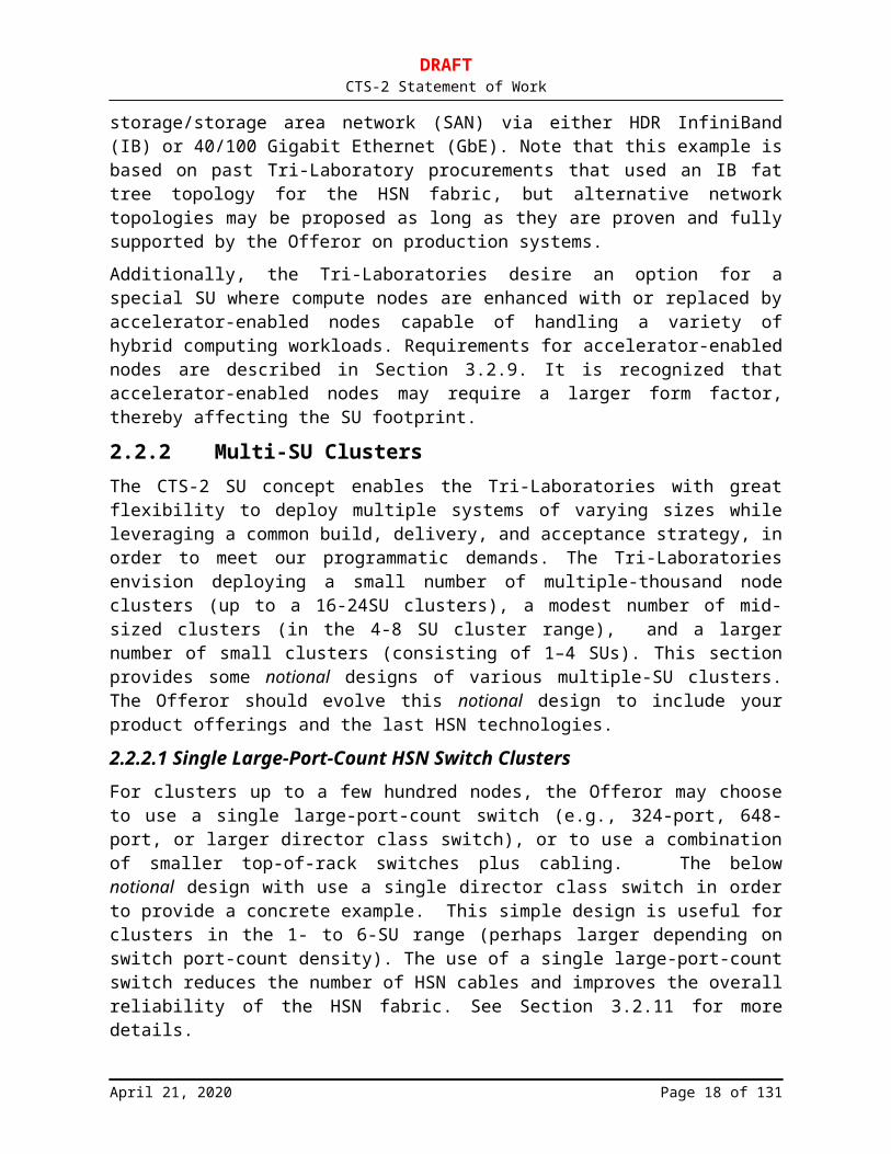
2.2.2 Multi-SU ClustersThe CTS-2 SU concept enables the Tri-Laboratories with great flexibility to deploy multiple systems of varying sizes while leveraging a common build, delivery, and acceptance strategy, in order to meet our programmatic demands. The Tri-Laboratories envision deploying a small number of multiple-thousand node clusters (up to a 16-24SU clusters), a modest number of mid-sized clusters (in the 4-8 SU cluster range), and a larger number of small clusters (consisting of 1–4 SUs). This section provides some notional designs of various multiple-SU clusters. The Offeror should evolve this notional design to include your product offerings and the last HSN technologies.
2.2.2.1 Single Large-Port-Count HSN Switch ClustersFor clusters up to a few hundred nodes, the Offeror may choose to use a single large-port-count switch (e.g., 324-port, 648-port, or larger director class switch), or to use a combination of
April 21, 2020 Page 12 of 86

DRAFTCTS-2 Statement of Work
smaller top-of-rack switches plus cabling. The below notional design with use a single director class switch in order to provide a concrete example. This simple design is useful for clusters in the 1- to 6-SU range (perhaps larger depending on switch port-count density). The use of a single large-port-count switch reduces the number of HSN cables and improves the overall reliability of the HSN fabric. See Section 3.2.11 for more details.
A single 4-SU cluster is depicted in Figure 2 using a notional 648-port HSN switch.
Figure 2. Example CTS-2 4-SU cluster.
Alternatively, the Offeror may propose using multiple top-of-rack (TOR) switches, with additional cabling, to accomplish the same goals. The trade-offs between cost savings and system reliability should be considered.
2.2.2.2 Large-Scale Multi-SU ClustersFor clusters larger than a single large-port-count switch, the Offeror may choose to build a fat-tree fabric using small-port-count edge switches (e.g., 36-, 48-, or 64-port single-switch application-specific integrated circuit (ASIC) switches) and large-port-count core switches (324-port, 648-port, or larger switches). This design reduces SU costs, eases node-to-switch integration, and reduces the maximum number of hops within the HSN fabric. Alternative network topologies that are fully supported may be offered.
Figure 3. Example CTS-2 18-SU cluster.
April 21, 2020 Page 13 of 86
DRAFTCTS-2 Statement of Work
3 CTS-2 Technical RequirementsThis section contains technical requirements for systems procured through the CTS-2 subcontract resulting from this RFP. In addition to addressing the requirements for initial SU deliveries, Offerors are asked to offer technology enhancements as options in future deliveries of SUs and to provide the price of those technologies in the proposed timeframe. Risks associated with the proposed roadmap shall be addressed in the Risk Management Plan (Section 6.4).
In addition to MRs and TRs identified in this Draft SOW, the Offeror may choose to propose any additional features (i.e., Offeror-proposed features) consistent with the objectives of the CTS-2 procurement and the Offeror’s product roadmap, which the Offeror believes will be of value to the Tri-Laboratories. MRs, TRs, and additional features proposed by the successful Offeror, and of value to the Tri-Laboratories, will be stated as firm requirements in a final negotiated SOW and incorporated in the resulting CTS-2 subcontract.
3.1 High-Level Hardware Summary Offeror will provide a high-level overview of the proposed SU design (Section 3.1.1) and its evolution (Section 3.1.3) over the CY21 through CY24 timeframe. The intent of this section is to have, in one place, a technical summary of the Offeror’s proposed SU deliveries. Offeror’s responses to the requirements in this section should be detailed and complete.
3.1.1 CTS-2 SU High-Level Architecture (TR-1)The Offeror will provide a detailed description of the features and functionality of all major components of the proposed CTS-2 SU. The Offeror will provide an architectural diagram of the CTS-2 SU, similar to Figure 1, labeling all component elements and providing bandwidth and latency characteristics (speeds and feeds) of, and between, elements. The Offeror will provide an architectural block diagram for each CTS-2 node-type bid, labeling all component elements and providing bandwidth and latency characteristics (speeds and feeds) of, and between, elements. The node architectural diagrams will specifically show and label the chipset used and denote independent PCIe and other buses and slots and label these with bus widths and speeds. In addition, for multi-socket nodes, the speed of the connection between sockets will be labeled.
The complexities of multicore processors may result in on-chip bandwidth and latency performance imbalances with respect to each core’s access to L2 cache, L3 cache, and/or off-chip main memory (DRAM/HBM). The Offeror will provide a detailed description of the proposed processor(s) and any performance imbalances that may exist that are in the 5–10% or higher range. Included in the processor description will be their various clock frequencies (e.g., scalar, vector, etc.), number and type of functional units, and pipeline latency. In addition, the Offeror will explain how various BIOS and firmware settings impact the amount of imbalance present within the processor chip. The Offeror will also describe any system-wide imbalances that may result from the integration of the proposed processor having differing amounts of imbalance within a cluster.
The Offeror will provide an architectural block diagram of the proposed HSN for the SU and for combining SUs in at least 1, 2, 4, 6, 8, 12, 18, and 24 multiples. The Offeror will provide a
April 21, 2020 Page 14 of 86
DRAFTCTS-2 Statement of Work
rack layout diagram for the proposed SU and floor layouts for the above selected examples between 1 to 24 SUs. If the Offeror proposes to deliver different SU packaging configurations with differing rack layouts in order to meet site-specific power and/or cooling requirements (see Section 5.3), then a rack layout diagram for each proposed SU packaging configuration will be provided. Any liquid cooling strategies with nontrivial facilities impacts should be described.
3.1.2 SU Requirements Summary Matrix (TR-1)The following matrix identifies the highest-priority technical requirements and will be completed by an Offeror in its entirety. Entries will be labeled N/A if the requirement is not offered. In addition, the system requirements summary matrix will be completed for any alternative proposed systems.
SU Summary Matrix Spreadsheet is provided as a separate RFP document.
3.1.3 SU Evolution Roadmap (TR-1)The Tri-Laboratories require that the SUs aggregated into a specific cluster at any site be as close to identical as possible. However, the Tri-Laboratories also require that when processor, interconnects, memory, and storage technology elements advance during the lifetime of the subcontract resulting from this procurement, these enhancements will be integrated into future SU deliveries without perturbing SU architecture or reliability significantly. Price/performance improvements over time may be delivered through price reductions, performance improvements, or both (such as roadmaps that maintain approximately the same balance of memory bandwidth and peak FLOP/s). It is suggested that the overall CTS-2 goals be considered in selecting the SU evolution roadmap to offer.
Offerors will describe the anticipated technology advances and the circumstances required to trigger their integration into future SU deliveries. Risks associated with tracking this schedule will be addressed in the Risk Reduction Plan section. Offerors need not propose retrofitting SU hardware with these enhancements after delivery. Offerors will consider at least the following technology enhancements:
1) Processor improvements within the same or better cost/performance envelopes2) New processor socket and/or chipset improvements3) Higher speed and other memory improvements4) Storage with higher performance and/or capacity, including HDD and SSD/NVMe5) New accelerators (Graphics Processing Units (GPUs), etc.)6) Power efficiency improvements including (air or liquid) cooling and power supplies
For each technology enhancement, the impact upon the overall SU design and implementation should be categorized as “low,” “medium,” or “high” and the major components that are impacted listed. Offerors will use the “low” impact designation to indicate that no other major components are impacted by the change. Offerors will use the “medium” impact designation to indicate that other major components of the SU require update, but not a new design, and the SU architecture does not change substantially. Offerors will use the “high” impact designation to indicate that other major components of the SU require redesign, and/or the SU architecture does change substantially, or that system software requires a significant change. Table 1 is a notional table of technology improvements and their impacts to the SU design. Offerors will provide a similar table outlining the proposed technology improvements over the lifetime of the CTS-2 subcontract.
April 21, 2020 Page 15 of 86
DRAFTCTS-2 Statement of Work
Offerors will list how those changes to the proposed hardware solution over the CTS-2 timeframe will change the offering relative to the software requirements in Section 3.3. Offerors will list these software changes and include their impact into the overall impact rating of “low,” “medium,” or “high.” For example, upgraded memory might be rated as “low” impact, while an upgraded processor could be “low” to “high” impact (depending on whether chipset changes are also involved).
Offerors will offer at least processor and memory improvements as well as beneficial technology enhancements deemed to have, at most, “medium” impact. Changes with “high” impact will be proposed if they deliver correspondingly high benefits.
Table 1. Notional Technology Improvements and Their Effects on SU Design
Item Item Upgrade Delivery Qtr
Attribute Overall SU Impact
Processor Frequency enhancements
X.X GHz clock Low
Processor Core enhancements Number of cores, core features
Low
Processor New socket Socket type, clock Medium to high, new motherboard, new memory type/speed
Processor Next generation processor
Processor name, socket, GHz clock, power
Medium or high, new motherboard, node design, new memory type/speed, new node design
Memory Speed enhancements More bandwidth Low
High Speed Network
Switches, NIC, cables High
Local Disk SSD/HDD speed and capacity improvements
Low
Accelerator Next generation accelerator
SSD/NVMe Next generation NVMe
Cooling or Power
Liquid cooling or power supply improvements
Improved efficiency
Low/medium/high
For proposed technology improvements that have medium or high impact to SU architecture design, Offerors will provide high-level SU architectural diagrams as defined in Section 3.1.1 for each.
3.2 SU Hardware RequirementsFor each of the following SU hardware requirements, Offerors will provide information for the first SU installation only (i.e. based on 2H CY2021 technology). Changes to the proposed SU hardware to meet these requirements over the subcontract timeframe are covered in Section 3.1.3.
April 21, 2020 Page 16 of 86

DRAFTCTS-2 Statement of Work
3.2.1 CTS-2 Scalable Unit (MR)The Offeror shall propose an SU design. Each SU the Offeror provides shall be based on at least one- or two-socket nodes. Two-socket nodes are the traditional choice for CTS. However, the Offeror may propose one- or four-socket nodes if they provide a cost/performance advantage. It is preferred that all nodes in the SUs to be aggregated into a specific cluster at any site be of the same processor and chipset revision. However, some flexibility will be allowed if the Offeror can not provide liquid cooled gateway or management nodes. See Section 5.5 for more details on power, cooling, and facility requirements. There shall be four node types within the standard SU: compute nodes, gateway nodes, a login node, and a management node. Some clusters may incorporate a fifth node type for GPUs or accelerators. All nodes shall be connected to the management Ethernet network and to the internal HSN fabric. Depending on the simulation environment at the deployment site, the login, management, and gateway nodes shall have the capability to attach to the site-supplied SAN or local area network (LAN) infrastructure via IB or Ethernet.
3.2.2 SU Management Ethernet (TR-1)The Offeror’s proposed SU will include a management Ethernet network in addition to the HSN fabric. The management Ethernet infrastructure will provide access to every node in the SU, with the ability to interconnect multiple SUs in a single Layer 2 domain up to the largest-size cluster that may be procured by the Laboratories. The management Ethernet will be aggregated with high quality, highly reliable, Ethernet switches with full bandwidth backplanes. The management Ethernet switches will contain a separate RJ-45 1000Base-TX (copper) management interface for administering the management switches via a separate management infrastructure. The management Ethernet switches will have a CLI-based OS for managing and configuring the switches themselves with Secure Shell (SSH) capabilities. All switch-to-switch links (uplinks) will be 10/40/100 GbE, while all switch-to-node links will be at least 1000Base-TX (copper). The management nodes will have 10 GbE connections into the management Ethernet network. The management Ethernet cables will be bundled in the racks with sufficient, but not excessive, slack to prevent stress and damage to both Ethernet cables and connectors. All management Ethernet connectors will have a snug fit when inserted in the management Ethernet port on the nodes and switches. The management Ethernet cables will meet or exceed Cat5e (1 GbE) and Cat6 (10 GbE) specifications for cable and connectors, preferably with snag-less RJ45 connectors with no connector boot. Management Ethernet reliability is specified in Section 4.1.
3.2.2.1 Enhanced Management Ethernet (TR-2)The Offeror’s management Ethernet network will provide 10 GbE connectivity to every node, preferably using an integrated (on-board) 10 GbE network interface controller (NIC). Switch-to-node links will use Cat6 or better copper cables. Offerors will indicate what level of bandwidth oversubscription is present in their enhanced Management Ethernet network design. Offerors will describe any advanced features of their management Ethernet switches, e.g., SDN capabilities.
3.2.3 Common SU Components (TR-1)The Offeror’s proposed SU will contain no significant component differences between nodes in air-cooled infrastructure racks or liquid-cooled compute rack configurations. This includes SU
April 21, 2020 Page 17 of 86
DRAFTCTS-2 Statement of Work
components such as, but not limited to, motherboards, processors, memory, integrated and add-on network cards, system chipsets and controllers (SATA/SAS, etc.), BIOS versions and settings, component firmware, power supplies, node chassis, and power distribution units (PDUs).
The Offeror should describe any component differences that exist between the proposed air-cooled infrastructure racks and the liquid-cooled compute racks in the SUs.
Note that the Tri-Laboratories require 480-V power and direct liquid cooling to at least the compute and accelerator nodes. See Section 5.3 for related system integration, power, and cooling requirements.
3.2.4 CTS-2 Node RequirementsThe following requirements apply to all node types except where superseded in subsequent sections.
The Offeror should consider proposing multiple potential processor technologies/providers for the CTS-2 CPU. Multiple CPU technologies provide risk mitigation and ensure that CTS-2 will be able to field a CTS-2 system on schedule, provide a stable and high-performance software environment, and meet Tri-Laboratory overall programmatic goals. If multiple CPU technologies are provided, the Tri-Lab CTS-2 technical team intends to select a single CPU technology for use in all CTS-2 SUs as part of “MS5: CTS-2 SU Architecture Decision Point (TR-1)” (see Section 6.8.5). This strategy allows the Offeror to propose multiple processor technologies, in the timeframe of the initial CTS-2 deliveries, with the Tri-Laboratories down-selecting to one processor technology via the Architecture Decision Point, followed by system deployments with that selected technology.
3.2.4.1 Processor and Cache (TR-1)The Offeror’s proposed processor SKU should represent the best cost/performance for the CTS-2 benchmarks. The processor for the base configuration will be balanced with respect to the performance concerns raised in Section 3.1.1. In addition, the Offeror may also suggest additional processor SKU(s) that improve the processor cost/performance effectiveness. The additional processor SKU(s) may have slight performance imbalances (see Section 3.1.1 for more details). At a socket level, those imbalances will not vary by more than 10% from the average of all cores. At a system level, the imbalances will not vary by more than 10% from the average of all nodes.
3.2.4.2 Node Performance (TR-1)The CTS-2 compute node will have significant performance capabilities as measured by the laboratory benchmark suite.
The objective of benchmarking requirements is to assist the Offeror in selecting the most promising technologies on a cost/performance basis for laboratory workloads. Projections naturally have uncertainty, however, the lower the uncertainty in benchmark projections the greater confidence the laboratories will have in their technology selection.
3.2.4.2.1 Benchmarks (TR-1)
The CTS-2 benchmarks will all be available at the following URL:
April 21, 2020 Page 18 of 86

DRAFTCTS-2 Statement of Work
https://hpc.llnl.gov/cts-2-benchmarks
This site will be maintained with updated information throughout the proposal response period, including updates to instructions for build and execution, as well as the rare possibility of a change in the baseline Figures of Merit (FOMs) due to late discovery of a bug or issue with the baselining procedures performed by the CTS-2 team. The entire set of benchmarks listed in Table 2 have been executed on the existing CTS-1 systems to provide baseline execution performance. The benchmark website provides the results of these runs as an aid to Offerors.
3.2.4.2.2 Benchmarking Procedures
Each benchmark will have its performance projected to a compute node in the proposed CTS-2 system. For all benchmark runs and projections, the code should not be modified unless explicitly allowed in the benchmark description on the benchmark website. Vendors are encouraged to use the best compiler options for each benchmark.
The projection methodology will be described in enough detail to allow recreation of the results if desired and possible. For example, if performance is projected from current hardware, then the compiler lines and versions, test hardware, and other relevant software used will be reported. How performance was scaled to the new node will be described. Other projection methodologies used, e.g., simulations of the proposed hardware, will be described in similar detail but may not be replicable by the labs.
The vendor will report the following values by filling in Table 3 and Table 4. In addition, the Offeror will report the compiler and compiler flags used, along with any code modifications in the “Benchmark Test Documents” provided with the RFP package . A template for this appendix will be available on the benchmark website.
For each benchmark a normalized FOM will be computed:
Si = projected FOMi / baseline FOMi
Then a node average will be computed by taking the harmonic mean of all the values
Snode=4
∑i=1
4
1/ Si
Vendors will report all of these values along with an SU FOM using the following tables. Note the SU FOM may only use compute nodes and should exclude gateway, login, and management nodes. To calculate this value multiply Snode by the number of compute nodes in an SU.
Table 2. CTS-2 Benchmarks
Code Lines of Code
Parallelism Language Description
HPCG 7600 MPI + OpenMP
C++ HPCG is a software package that performs a fixed number of multigrid preconditioned (using a symmetric Gauss-Seidel smoother) conjugate gradient (PCG) iterations using double precision (64-bit) floating point
April 21, 2020 Page 19 of 86
DRAFTCTS-2 Statement of Work
Code Lines of Code
Parallelism Language Description
values.
LAGHOS 2000+dependency on MFEM
MPI + RAJA
C++ Laghos solves the time-dependent Euler equation of compressible gas dynamics in a moving Lagrangian frame using unstructured high-order finite element spatial discretization and explicit high-order time-stepping. It is built on top of a general discretization library (MFEM) and supports two modes: *full assembly*, where performance is limited by the data motion in a conjugate gradient (CG) solve, and *partial assembly*, where performance depends mostly on small dense matrix operations and the CG solve communication.
Quicksilver 10,000 MPI + OpenMP
C++ Monte Carlo transport benchmark with multi-group cross section lookups. Stresses memory latency, significant branching, and one large kernel that is 1000’s of lines in size.
Snap 3000 MPI + OpenMP
Fortran SNAP serves as a proxy application to model the performance of a modern discrete ordinates neutral particle transport application.
Table 3. Application Projections
Application
Baseline FOM Projected FOM Si
SNAP Lab provided
HPCG Lab provided
LAGHOS Lab provided
Quicksilver Lab provided
Table 4. Node and SU Projections
FOM Compute Nodes Projected
Snode 1
SSU
3.2.4.3 Node Delivered DGEMM Performance (TR-1)The SU nodes will be configured to deliver at least 1.5 TF/s per socket of compute performance when running a DGEMM kernel. In addition, Offerors will report the single-core performance of running a DAXPY kernel. Offerors will report with proposal the DGEMM performance running for each bid CTS-2 node type. Offerors may use the size kernel for each of these benchmarks that produces the best performance.
3.2.4.4 Node Socket Configuration (TR-2)The SU nodes may be configured with 1-, 2-, or 4-socket solutions. The Tri-Laboratories prefer well-balanced solutions.
April 21, 2020 Page 20 of 86

DRAFTCTS-2 Statement of Work
3.2.4.5 Node Memory Interface (TR-2)The SU nodes memory interface will be capable of supporting DDR4-3200 or faster memory (e.g., DDR5, HBM). The Offeror will describe the node memory interface, including the number of memory channels and aggregate peak memory bandwidth per node.
3.2.4.6 Node Chipset and BIOS (TR-2)The SU node chipset and BIOS will be common across all SU nodes (e.g., compute, login, gateway, and management nodes).
3.2.4.7 Node Memory (TR-1)The SU nodes will be configured with at least 2.0 GB of memory per processor core (or at least 1.0 GB per CPU core for the HBM option in Section 3.2.4.8.3). The Offeror’s solution may need to exceed this 2.0 GB of memory per processor core in order to meet additional CTS-2 memory related requirements, but more than 4.0 GB per CPU core is not desirable. The memory will be DDR4-3200 or faster and configured in maximum performance mode. All memory channels will be populated equally. Dual rank memory is preferred as long as it can operate at full clock rate. The Offeror will propose and describe the most reliable, highest performance memory configuration.
3.2.4.8 Node Memory TypeThe Tri-Laboratories have traditionally met its CTS memory performance and reliability requirements with x4 Chipkill DDR memory. However, with the rise of non-HPC markets, memory manufacturers have pushed Chipkill features to their larger capacity memory modules. This trend, coupled with an increasing number of memory channels per CPU socket, drives Chipkill memory to much greater than 2 GB per CPU core. The Tri-Laboratories may consider non-Chipkill or other memory options that can still meet its reliability requirements while achieving a capacity per CPU core close to its target (see Section 3.2.4.7).
3.2.4.8.1 Node Memory Module Type with Chipkill (TR-1)
The Offeror’s SU nodes will utilize x4 memory modules capable of Chipkill ECC. The Offeror will state the expected peak memory bandwidth per node (in GB/s) and the expected rate of uncorrected memory errors per node in Failures in Time (FIT) units (uncorrectable memory errors expected per node in a billion hours). For each metric, the Offeror must describe how they arrived at their estimates (e.g., component suppliers, published research, field experience, etc.).
3.2.4.8.2 Node Memory Module Type without Chipkill (TR-1)
If the baseline memory configuration with Chipkill (Section 3.2.4.8.1) exceeds 4.0 GB per core, the Offeror will propose a lower-cost memory option, configured to meet the memory requirement (Section 3.2.4.7) but relaxing the Chipkill requirement. The Offeror will describe how to configure processors for maximum memory performance while minimizing the interrupts to the application caused by uncorrectable memory errors. The Offeror will state the expected peak memory bandwidth per node (in GB/s) and the expected rate of uncorrected memory errors per node in FIT units (uncorrectable memory errors expected per node in a billion hours). For each metric, the Offeror must describe how they arrived at their estimates (e.g., component suppliers, published research, field experience, etc.).
April 21, 2020 Page 21 of 86
DRAFTCTS-2 Statement of Work
3.2.4.8.3 Higher Performance Memory Option (TR-2)
The Offeror will describe when HBM memory could become available on compute nodes, and how it should be configured for maximum performance while minimizing the expected interrupts to the application caused by uncorrectable memory errors. The expected levels of performance and reliability will be described. The Offeror will state the expected peak memory bandwidth per node (in GB/s) and the expected rate of uncorrected memory errors per node in FIT units (uncorrectable memory errors expected per node in a billion hours). For each metric, the Offeror must describe how they arrived at their estimates (e.g., component suppliers, published research, field experience, etc.).
For compute nodes configured with HBM, the minimum capacity requirement is 1.0 GB per CPU core, and higher capacity (2.0 GB or more) per core is preferred. A second tier of DDR memory is not expected in the baseline HBM compute node configuration.
3.2.4.8.4 Large DDR Memory Capacity Node (TR-2)
The Offeror will provide optional DDR memory configurations for all SU nodes, including 4.0, 8.0, and 16.0 GB of DDR memory capacity per CPU core.
3.2.4.9 Node Delivered Memory Performance (TR-1)The SU nodes will be configured to deliver at least 150 GB/s per processor socket of memory bandwidth when running one copy of the Streams benchmark per CPU core.
The Offeror will report with proposal the Streams performance running one copy of the Streams benchmark per core, for each bid CTS-2 node type. See https://hpc.llnl.gov/cts-2-benchmarks or http://www.cs.virginia.edu/stream/ for the Streams benchmark. In addition, the Offeror will report the performance of Streams when only one core on the node is running the benchmark.
3.2.4.10Hardware Memory Uncorrectable Error Detection (TR-1)The SU nodes will include a hardware mechanism to detect memory uncorrected errors and report them promptly to the Linux operating system, either directly or via system firmware. The Offeror will describe this capability, with a particular emphasis on the following requirements:
This mechanism will be capable of interrupting operations when an uncorrected error occurs so that the Linux operating system may take immediate action.
This mechanism will provide sufficient information so that the Linux operating system may identify the affected major memory component (e.g., the exact DIMM field replaceable unit (FRU) identified by the label visible on the motherboard, or the HBM memory stack) and log it with descriptive detail, preferably without requiring an atypical reboot or a manual procedure to recover the error from a system event log. In all cases, more detailed fault location and fault type reporting is preferable.
3.2.4.11Hardware Memory Corrected Error Detection (TR-1)All SU node memory will be reliable and capable of detecting and correcting most errors. The Offeror will describe this capability, with a particular emphasis on the following requirements:
The SU nodes will include a lightweight hardware mechanism to detect and count corrected memory errors. The Offeror will estimate the operating system plus any firmware overhead (in
April 21, 2020 Page 22 of 86
DRAFTCTS-2 Statement of Work
percent) for both error-free operation and the expected corrected error rates. While some loss of events may be unavoidable, high rates of memory corrected errors will not cause substantial undercounts.
This hardware mechanism will keep track of sufficient information so that the Linux operating system may identify the affected major memory component. In all cases, more detailed fault location and fault type reporting is preferable.
The node memory controller will expose a publicly documented interface that is documented in sufficient detail so that Tri-Laboratory personnel can actually query and program this facility from a Linux utility to obtain the type of correction mechanism actually enabled, collect the memory corrected error counts per major memory component, and also reset all the error counts to zero.
The node memory controller will expose defective major memory components for which the hardware/firmware resilience functionality compensates (e.g., sparing) to the Linux operating system, at least down to the level of major memory components.
3.2.4.12Hardware Memory Controller Capabilities and Configuration (TR-1)The Offeror’s processor memory controller, memory configuration capabilities, and optional memory settings will be exposed through a publicly documented interface to the Linux operating system. The Offeror will describe this capability, with a particular emphasis on the following requirements:
The Offeror will describe hardware/firmware memory controller capabilities. Prior to delivery, these capabilities will be documented in sufficient detail so that Tri-Laboratory personnel can actually query and program this facility from a Linux utility.
The memory controller configuration capabilities and options exposed through this interface may include, but are not limited to: actual memory error detection state (enabled/disabled),the type of correction mechanism currently enabled, memory RAS and CAS timing setting, memory chip and memory bus speed, memory width (x4, x8), memory ranks (single, dual), memory interleaving, memory mirroring, whether the memory controller or system firmware does scrubbing of corrected memory errors, etc. If additional capabilities exist, describe how they could be queried and programmed from the Linux level.
This capability will enable deterministic control from the Linux level (without a competing source of control potentially silently undoing what the operating system has commanded).
3.2.4.13Node Memory Testing (TR-1)The Offeror will describe the internal process used to evaluate and test memory for performance, stability, and reliability. The description should include processes used before memory installation into systems and processes used after installation. The Tri-Laboratories are particularly interested in how such testing may result in more reliable memory with a significantly reduced error rate over the lifetime of the system.
3.2.4.14Extended Memory Testing (TR-1)The Offeror will describe any additional memory testing procedures that may be possible, yet beyond the Offeror’s standard memory testing procedures. The Offeror may recommend
April 21, 2020 Page 23 of 86

DRAFTCTS-2 Statement of Work
additional testing procedures that improve the overall reliability of system memory (DDR or HBM).
3.2.4.15Node I/O Configuration (TR-2)The SU node chipset will be configured with two independent PCIe4 (or faster) buses and one PCIe4 16x (or faster) slot per bus. The SU node PCIe infrastructure will be fully compatible with both the proposed HSN HCA and the proposed 10/40/100 GbE NIC.
3.2.4.16Node HSN Adapter (TR-1)The Offeror’s SU nodes will be configured with at least one HSN adapter per compute node to connect with the SU’s HSN fabric.
3.2.4.17Node Power (TR-2)The SU nodes components together will utilize less than 250 W per socket when idle and less than 400 W per socket when running a copy of Linpack on every CPU core, with sufficient power ramp rates to support bulk synchronous transitions between idle and maximum power. Accelerator nodes will meet this requirement, excluding the power requirement for the accelerator(s). Related to this specification, internal power supplies will meet at minimum the 80 PLUS Bronze level criteria, as specified at
https://www.plugloadsolutions.com/80PlusPowerSupplies.aspx.
Power supplies will maintain a true power factor of 0.9 or greater at 50% rate load and higher. Higher-efficiency power supplies are preferable. The test procedure for such measurements may be found at http://www.efficientpowersupplies.org. Unrated power supplies (of any output) can be sent to http://80plus.org and publicly posted to the website for a testing and reporting fee. All racks will provide a connection for grounding.
3.2.4.18No Local Hard Disk (TR-1)The default SU compute and gateway node configuration will not include a traditional rotating disk-based hard drive.
3.2.4.19Non-Volatile Storage Option (TR-2)The Offeror will propose non-volatile storage options (NVMe and/or SSD) internal to all SU node types, with at least triple the node memory capacity. Non-volatile storage endurance will allow at least one full device rewrite per day over at least a four-year storage lifespan. High bandwidth, low latency solutions are preferred. Non-volatile storage performance characteristics and system software requirements to access and manage the storage will be described.
3.2.4.20Local Hard Disk (TR-2)The Offeror will propose local hard disk options internal to compute, gateway, login, and management SU node types. The local hard disk performance characteristics and any system software requirements will be described. The number of available local hard disks may vary per node type. The Offeror will describe the various alternatives for each node type.
April 21, 2020 Page 24 of 86

DRAFTCTS-2 Statement of Work
3.2.4.21Node Form Factor (TR-2)The Offeror will provide SU compute nodes with an equivalent form factor of not more than 2U.
Denser solutions (including blades) meeting the power and cooling requirements in Section Error: Reference source not found and facilities requirements in Section 5.3 are desired.
3.2.4.22Node Management Ethernet Connection (TR-1)The node will have at least one integrated copper 1-GbE connection to the management Ethernet network.
3.2.5 Compute Node Requirements (TR-1)The compute nodes will meet the requirements in Section 3.2.4 (i.e., no additional requirements).
3.2.6 Gateway Node Requirements (TR-1)The following requirements are specific to the gateway nodes. The gateway nodes will meet the requirements in Section 3.2.4 unless superseded by the requirements listed below.
3.2.6.1 Gateway Node Count (TR-1)The Offeror will configure the SU with four gateway nodes. The Tri-Laboratories may wish to negotiate a different number of gateway nodes on a per-cluster basis.
3.2.6.2 Gateway Node I/O Configuration (TR-1)The Offeror’s SU gateway node chipset will be configured with sufficient PCIe4 (or faster) buses and sufficient slots to drive both the SU internal HSN adapter and one SAN network interface. For the SAN interface, the Offeror will support both HDR IB and 100 GbE. The gateway node must be capable of driving the HSN interface and the SAN interface at the same time and at least 90% of peak. The SU gateway node PCIe4 (or faster) infrastructure will be fully compatible with the proposed HSN and IB/Ethernet network cards.
3.2.6.3 Gateway Node HDR IB Card (TR-1)The SU gateway node will be configured with one 4x HDR IB adapter to connect to site SAN. The Offeror will provide and support an open-source IB driver for the RHEL 8 or later kernels. The IB adapter will natively support standard IB protocols.
3.2.6.4 Gateway Node Delivered IB SAN Performance (TR-2)The SU gateway node will be configured to support a minimum of 40 GB/s, from the cluster HSN to HDR IB SAN, delivered via IB routing bidirectional bandwidth (counting both directions). The Offeror will provide fully documented benchmark data including options demonstrating the minimum performance utilizing the iperf benchmark with the Offeror’s response.
3.2.6.5 Gateway Node 100 GbE Card (TR-1)The SU gateway node will be configured with one 100/40/10 GbE NIC with SR optics, capable of delivering an aggregate 100/40/10 GbE peak performance and at least 90% of peak. The Offeror will provide and support an open-source Ethernet driver for RHEL 8 or later kernels.
April 21, 2020 Page 25 of 86

DRAFTCTS-2 Statement of Work
All network interfaces and device drivers will support 9KB jumbo frame or greater MTU operation and be at the latest firmware supported by the NIC vendor.
3.2.6.6 Gateway Node Delivered 100 GbE SAN Performance (TR-2)The SU gateway node will be configured to support a minimum of 16 GB/s from the cluster HSN to one 100 GbE, delivered via Ethernet routing bidirectional bandwidth (counting both directions). The Offeror will provide fully documented benchmark data including options demonstrating the minimum performance utilizing the iperf benchmark with the Offeror’s response.
3.2.7 Login Node Requirements (TR-1)The following requirements are specific to the login nodes. The login nodes will meet the requirements in Section 3.2.4 unless superseded by the requirements listed below. Login nodes will be used for user access, which includes application development, job launch, compiling, and debugging.
3.2.7.1 Login Node Count (TR-1)The Offeror will configure one login node per SU. The Tri-Laboratories may wish to negotiate a different number of login nodes on a per-cluster basis.
3.2.7.2 Login Node I/O Configuration (TR-1)The SU login node chipset will be configured with sufficient PCIe4 (or faster) buses and sufficient PCIe4 slots to drive the HSN adapter, and dual-port 100 GbE card at full line rate. The SU login node PCIe4 (or faster) infrastructure will be fully compatible with the proposed HSN adapter and 100 GbE card.
3.2.7.3 Login Node Network Configuration (TR-1)The SU login nodes will be configured with one PCIe4 (or faster) HSN adapter for access to the HSN fabric. The SU login node will be configured with 100 GbE multimode or single-mode fiber (depending on site preference) supported by a PCIe4 (or faster) bus for access to the site 100 GbE infrastructure. The 100 GbE card should be capable of single or dual-port function. The SU login node will be configured with either one PCIe4 (or faster)100 GbE NIC or one HDR IB HCA for access to site SAN. These various connections will be in addition to any ports required for management functions. The Offeror will provide and support open-source Ethernet and IB drivers for RHEL 8.x and later kernels and updated NIC firmware to support BIOS/kernel levels. The driver and firmware levels will be at the latest firmware supported by the NIC vendor. All network interfaces and device drivers will support 9KB jumbo frame or greater MTU operation.
3.2.7.4 Login Node Storage Configuration (TR-2)The SU login nodes will be configured with one 4.0 TB (or larger) highly reliable non-volatile storage (NVMe or SAS SSD) drive. The drive should be directly accessible for servicing from the exterior of the login node.
3.2.8 Management Node Requirements (TR-1)The following requirements are specific to the management nodes. The management nodes will meet the requirements in Section 3.2.4 unless superseded by the requirements listed below.
April 21, 2020 Page 26 of 86

DRAFTCTS-2 Statement of Work
Management nodes will be used for various administrative tasks and to remote boot the compute and gateway nodes.
3.2.8.1 Management Node Count (TR-1)The Offeror will configure the SU with one management node per SU. The Tri-Laboratories may wish to negotiate a different number of management nodes on a per-cluster basis.
3.2.8.2 Management Node I/O Configuration (TR-1)The SU management nodes chipset will be configured with sufficient PCIe4 (or faster) buses and sufficient slots to drive an HDR IB HCA, Ethernet NICs, and HSN adapter at full line rate. The SU management node PCIe4 infrastructure will be fully compatible with the proposed IB HCA, HSN, and Ethernet cards.
3.2.8.3 Management Node Network Configuration (TR-1)The SU management nodes will be configured with one PCIe4 (or faster) HSN adapter for access to the HSN fabric, one PCIe4 (or faster) 4x HDR IB card or one single/dual-port 100 GbE for access to the site SAN infrastructure, and a single/dual-port 10 GbE multimode SR fiber supported by PCIe4 (or faster) for access to the cluster management Ethernet infrastructure. The Offeror will provide and support open-source 10/100 GbE and 4x HDR IB drivers for the RHEL 8 and later kernels. All network interfaces and device drivers will support 9KB jumbo frame or greater MTU operation and be at the latest firmware supported by the NIC vendor.
3.2.8.4 Management Ethernet Connection (TR-1)The management node will have at least one 10/40 GbE connection to the management Ethernet network.
3.2.8.5 Management Node RAID Configuration (TR-1)The SU management nodes will be configured with at least one highly reliable hardware RAID configuration utilizing at least eight active 12-Gb near-line SAS disks with an aggregate capacity of at least 4 TB, plus an identical hot spare disk. The RAID controller should be capable of at least JBOD, JBOD pass-through, RAID5, RAID6, and RAID10. The RAID controller will be capable of being flashed to initiator target (IT) mode.
The RAID arrays will deliver at least 1 GB/s (best case, using outer cylinders) and 500 MB/s (minimum, using inner cylinders) aggregate sustained read/write bandwidth, and at least 90% of that performance should be obtainable from the Linux XFS file system mounted on each partition. The RAID arrays will deliver an average seek time of better than 4 ms and average latency of 4.5 ms. The individual disks will feature nonrecoverable read errors of 1 sector per 1015 bits or better and a mean time between failures (MTBF) rating of at least 1.2 million hours.
3.2.8.5.1 Management Node Non-Volatile Storage Configuration (TR-1)
The Offeror will propose a non-volatile storage (NVMe and/or SSD) option internal to the SU management nodes utilizing at least two devices plus one hot spare device with at least 4 TB total usable capacity. Non-volatile storage endurance will allow at least 1 full device rewrite per day over at least a four-year storage lifespan. Non-volatile storage devices should have medium
April 21, 2020 Page 27 of 86
DRAFTCTS-2 Statement of Work
to high write endurance to support heavier write workloads. High bandwidth, low latency solutions are preferred.
3.2.8.5.2 Hard Drive Diagnostic Lights (TR-2)
Failed hard drives will be indicated by external lights on the node chassis for easy identification during replacement.
3.2.8.6 Management Node Accessory Configuration (TR-2)The SU management nodes will be configured with one read-only (not read/write) Blu-ray/DVD/CD bootable device. Drives will be directly accessible for servicing from the exterior of the management node.
3.2.9 Accelerator Node Requirements The following requirements are specific to the accelerator nodes. The accelerator nodes will meet the requirements in Section 3.2.4 unless superseded by the requirements listed below. Note that the benchmarks described in section 3.2.4.2 apply only to the CPU’s on the accelerator node, not the GPU(s). The accelerator nodes would replace compute nodes in an SU. The Tri-Laboratories may wish to negotiate the number of accelerator nodes on a per-cluster basis.
3.2.9.1 Accelerator Node General Requirement (TR-1)The accelerator-enhanced nodes will utilize the same processors, BIOS, memory, and HSN interconnect as the baseline SU nodes. A common chipset between SU node types is highly desirable. There will be sufficient PCIe4 (or better) slots to accommodate the number of accelerators specified, plus the HSN adapter. All slots will be capable of operating at full bandwidth simultaneously. If an alternative accelerated SU solution is offered, the accelerator nodes will be fully described.
The accelerator node may have power, cooling, and a form factor that differs from the other SU node types.
3.2.9.2 Accelerator Node Configuration (TR-1)The Offeror will provide a minimum of one and two accelerators per socket. Options for up to four accelerators per CPU socket is desirable.
3.2.9.3 Accelerator Memory Requirement (TR-1)The Offeror will describe the memory capacity options and Streams bandwidth numbers on all proposed accelerators.
3.2.9.4 Accelerator Type (TR-1)The Offeror will provide accelerator options from multiple GPU vendors. Other non-GPU accelerators may also be proposed.
3.2.10 Node Firmware RequirementsThe requirements below apply to all nodes types except where called out as specific to a particular node type. The term firmware includes BIOS, Unified Extensible Firmware Interface (UEFI), and other software below the Linux kernel level.
April 21, 2020 Page 28 of 86
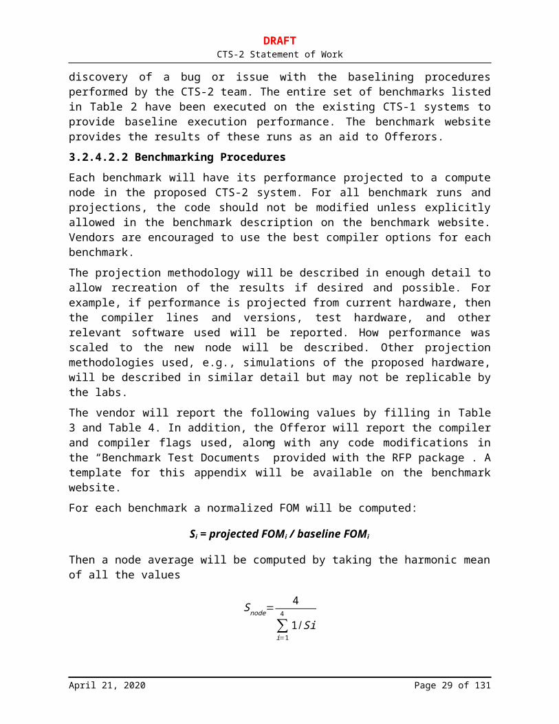
DRAFTCTS-2 Statement of Work
3.2.10.1Node Firmware (TR-1)The Offeror’s SU nodes will include a fully functional firmware that will take a node from power-on or reset state to the start of the Linux kernel as loaded from a network connection or local drive (if a local drive is installed). The provenance of the firmware (e.g., vendor, etc.) must be specified.
3.2.10.2Node Firmware Tools and Documentation (TR-1)The Offeror will provide comprehensive firmware documentation for the delivered SU nodes. This documentation will include descriptions of all parameters and default factory settings, how to modify them, and how to use the tools to manage the firmware. The documentation will specify the functionality, power, and performance/latency implications of relevant firmware settings. A complete set of Linux-based command line tools will be provided to manage firmware.
3.2.10.3Remote Network Boot (TR-1)All provided node firmware will be capable of initially booting the node from a remote OS image across the management Ethernet network using protocols such as PXE, BOOTP, or DHCP.
3.2.10.4Node Initialization (TR-1)The node firmware initialization process will complete without human intervention (e.g., no F1 keystroke to continue) or in the event of failure, fail with an error message written to the console. The time required for a node’s firmware to take the node from a power-on or reset state to the start of the loading of the Linux kernel boot image will be less than thirty (30) seconds. Note that this includes the power-on self-test (POST) phase configured with minimal POST hardware checks. Shorter times are highly desirable.
3.2.10.5Firmware Error/Interrupt Handling (TR-1)All SU node firmware will permit reporting chipset errors, memory errors, sensor conditions, interrupts or traps, hardware/firmware actions, etc., up to the Linux level. The delivered firmware may respond to these conditions directly (as configured), but the Linux operating system will be made aware of all such conditions and actions in sufficient detail to monitor and manage the system. The Offeror will describe these capabilities (including any limitations) and their operation, including estimates of expected firmware and operating system overheads (in percent).
3.2.10.6Firmware Security (MR)The principal function of the provided firmware shall be to perform node hardware initialization, power-on self-testing, and turn-over of operation to the OS boot loader. The firmware shall not perform any kind of extraneous automated or uncontrolled I/O to disks, networks, or other devices beyond that required to read or write firmware images, CMOS parameters, and device or error registers as required for booting, firmware configuration, power-on testing, and hardware diagnostics and configuration. Under no circumstances shall the firmware itself be allowed to directly capture or write user data to any location. If the firmware has such capabilities but is configured to disable them, then a formal testing process
April 21, 2020 Page 29 of 86
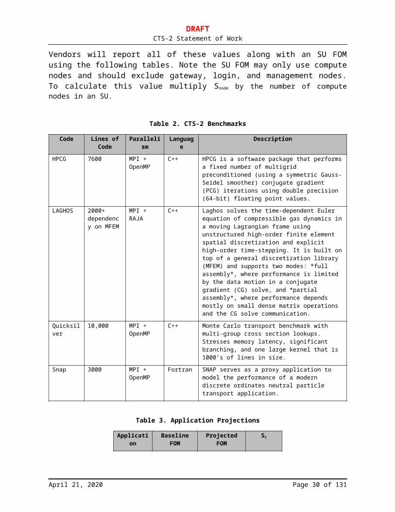
DRAFTCTS-2 Statement of Work
shall be performed by the Offeror and the results of such tests shall be provided to conclusively demonstrate that such features are in fact disabled.
The Offeror shall provide a certification document indicating that the firmware strictly meets the conditions specified in this section. Future updates of the firmware shall be accompanied by a new certification appropriate for that specific firmware version.
3.2.10.7Plans and Process for Needed Firmware Updates (TR-1)A written plan will be submitted with the Offeror’s proposal(s) outlining the Offeror’s plans and process to provide firmware updates to address problems or deficiencies in the areas of functionality, power, performance/latency, and security. The plan will outline a process that the Offeror will follow to identify, prioritize, and implement firmware updates in general and for addressing any specific Tri-Lab and/or DOE security related issues and concerns that may be raised. The Offeror’s plan will be finalized after subcontract award and included as an early deliverable for the SOW in the subcontract.
If a firmware update can render the node inoperable (e.g., due to incorrect firmware signature), any required repairs will be the Offeror’s responsibility.
3.2.10.8Failsafe/Fallback Boot Image (TR-1)The firmware will employ a failsafe/fallback booting capability in case of errors in the default firmware image during the default firmware boot process, or during a firmware flash operation. The node will reach a minimum state allowing for the diagnosis of errors. This capability will not require the use of any external writeable media (e.g., flash disk, etc.) and preferably no external media at all.
3.2.10.9Firmware Upgrade and Restore (TR-1)The Offeror will provide a hardware and software solution that allows a Linux command line utility or utilities to update, restore, and verify the firmware image(s). This mechanism will not require booting an alternative operating system (e.g., Windows or DOS).
3.2.10.10 CMOS Parameter Manipulation (TR-1)The Offeror will provide a mechanism to read (get) and write (set) individual CMOS parameters from the Linux command line or in a scalable out-of-band method that updates at least 500 nodes at a time. In particular, CMOS parameters such as boot order will be modifiable from the Linux command line. In addition, there will be accessible CMOS parameters that can disable any power management or processor throttling features of the node. The Linux command line utility will also allow reading all CMOS parameters (backup) and writing all CMOS parameters (restore). A Linux-based method to verify consistency of all CMOS parameters (excluding node- or time-dependent ones) will be provided and be fully documented. Reading or writing CMOS parameters will not require booting an alternative operating system or interacting with firmware menus or a firmware command-line interface. Such a capability will scalably function across the SU from within Linux shell scripts and/or the Linux Expect utility and not require navigation of firmware menus.
3.2.10.11 Firmware Command Line Interface (TR-1)A Linux command-line interface will be provided to interact with the delivered firmware. This interface will provide access to any other firmware functionality above and beyond that
April 21, 2020 Page 30 of 86

DRAFTCTS-2 Statement of Work
described in Section 3.2.10.10 and may be integrated with the tools associated with CMOS manipulation if both are provided. This capability will function from within Linux shell scripts and/or with the Linux Expect utility and will not require navigation of firmware menus.
3.2.10.12 Serial Console Over LAN (TR-1)The firmware will directly provide a remote serial console capability over an Ethernet management network. This capability will support the remote management features of Section 3.2.12.
3.2.10.13 Power-On Self-Test (TR-2)As a configurable option, the POST will be comprehensive, detecting hardware failures and identifying the failing FRU during the power-up boot sequence. All POST failures will be reported to the serial console and through the remote management solution in Section 3.3.7.
3.2.10.14 Programmable LED(s) (TR-3)The Offeror will provide nodes with either programmable LED(s) or a programmable front alphanumeric panel for run-time diagnostics. Access to these will be made available to the firmware as well as Linux.
3.2.11 High-Speed NetworkThe SU will be built with an HSN fabric that supports the OpenFabrics software stack based on RHEL 8. All speeds given below are unidirectional. HSN fabrics capable of 200 Gb/s are of most interest, with options for 100/200 Gb/s host adapters. These configurations would allow a full 200 Gb/s fabric or a 2:1 tapered fabric at the top-of-rack switch level.
The Offeror should consider proposing two potential networking technologies for the CTS-2 HSN. Multiple HSN technologies provide risk mitigation and ensure that CTS-2 will be able to field a CTS-2 system on schedule, provide a stable and high-performance software environment, and meet Tri-Laboratory overall programmatic goals. If two HSN technologies are provided, the Tri-Lab CTS-2 technical team intends to select a single HSN technology for use in all CTS-2 SUs as part of “MS5: CTS-2 SU Architecture Decision Point (TR-1)” (see Section 6.8.5).
3.2.11.1Fully Functional High-Speed Network (TR-1)The Offeror will propose a fully functional 200 Gb/s unidirectional network fabric with all required hardware (e.g., switches, cables, and connectors) and software (Sections 3.3.1, 3.3.1.4). The Offeror will propose both managed and unmanaged HSN switches. The delivered HSN software will be capable of running on the RHEL 8.x (TOSS 4.x) or later operating system. The delivered HSN hardware and software will be capable of driving copper or optical cables. If necessary, the Offeror will assist the Tri-Laboratories, OpenFabrics, and Red Hat community with porting the HSN software to the SU interconnects.
3.2.11.2HSN Host Adapter Performance and Functionality (TR-1)The Offeror will provide a HSN host adapter capable of 200 Gb/s using a PCIe4 16x (or faster) interface. The Offeror will describe any offload capabilities of the proposed HSN NIC.
April 21, 2020 Page 31 of 86
DRAFTCTS-2 Statement of Work
3.2.11.3HSN Node Bandwidth, Latency, and Throughput (TR-1)The Offeror’s SU HSN will deliver at least 90% of peak network bandwidth, both unidirectional and bidirectional, when exchanging data between any two nodes in the SU. The SU HSN will deliver an MPI ping/pong latency (round trip divided by two) of no more than 1.5 µs as measured between any and all two-MPI-task pairs in the SU, each with one MPI task per core.
The Offeror’s SU HSN will deliver an aggregate processing rate of at least 4.0 106 messages per second per core, utilizing an application with one MPI task per core on each node, between any two nodes in the SU. The performance will scale linearly up to 200 106 messages per second per node.
The Offeror will report the compute node delivered MPI bandwidth, latency, and messaging throughput benchmarks over the HSN host adapter attached to a PCIe4 (or faster) bus between two nodes utilizing 1 MPI task per node, 1 MPI task per socket, and 1 MPI task per core on each node.
Included in the bandwidth report will be the minimum size message needed to achieve the stated bandwidth. In addition, the Offeror will report the time it takes to perform an 8-byte AllReduce operation with 1 MPI task per node, 1 MPI task per socket and 1 MPI task per core on 64 nodes.
The Tri-Laboratories suggest the “perftest,” “presta,” and “osu_mbw_mr” benchmarks from the following sites:
Perftest is available on the OpenFabrics website: https://github.com/linux-rdma/perftest. Presta is available at: https://asc.llnl.gov/coral-2-benchmarks/downloads/phloem-
1.4.4.tar.gz. Osu_mbw_mr is available at: http://mvapich.cse.ohio-state.edu/benchmarks/.
3.2.11.4High-Speed Network Advanced Features (TR-1)The Offeror will provide a detailed description of any advanced network features. These features may include, but are not limited to: adaptive routing, collective offloads, congestion management, GPU direct, NVMe over fabrics, Quality of Service (QoS), and reliability features.
3.2.11.5High-Speed Network Fat-Tree Topology (TR-1)The Offeror’s HSN will be capable of supporting a fat-tree fabric topology that is a full, nonblocking network. The HSN will have as much bandwidth available for SU nodes as available for connection to second-stage switches. The Offeror’s HSN solution will support cluster sizes up to 24 SUs.
Large radix single-ASIC switches are preferred. Such single-ASIC top-of-rack (TOR) switches can be used to construct tapered fabrics (e.g., 2:1 global network tapering) at a modest scale of 6–12 SU clusters. Larger, multistage switches (e.g., 500 to 1,000 ports or larger) are also desired to scale to 24 SUs in a three-stage fabric.
April 21, 2020 Page 32 of 86

DRAFTCTS-2 Statement of Work
3.2.11.6Multi-SU Director-Class Switches (TR-1)The HSN will be capable of directly connecting at least 4 SUs together with a single director-class switch. The HSN will be capable of expanding to a cluster with, at least, up to 24 SUs with the addition of Offeror-supplied spine and edge switches and cables.
3.2.11.7High Speed Network Alternative Topologies (TR-1)The Offeror will propose alternative topologies (e.g., Dragonfly, multidimensional torus/mesh, hypercube, etc.). The Offeror will describe the advantages and disadvantages of the alternative topology relative to a full fat-tree topology. The Offeror will describe how the proposed alternative topology can be used to scale from 1 to 24 SUs. The Offeror will also describe the impact of the alternative topologies on job placement and scheduling as well as gateway node placement in the HSN fabric. The Offeror will fully support the proposed alternative topologies on the CTS clusters.
In order to mitigate risks on the network topology, HSN solutions that could be reconfigured from the proposed alternative topology to a fat-tree topology are preferred. Such reconfiguration would only take place in the event the proposed alternative topology fails to meet CTS requirements in the field.
3.2.11.8High-Speed Network Cabling Pattern (TR-1)The Offeror will connect compute nodes to the HSN switches such that the successively numbered compute nodes can communicate through a minimum number of ASIC switch chips (through a minimum number of hops).
The Offeror will describe the proposed cabling pattern and cable types of an example multi-SU platform using supported topologies from Sections 3.2.11.5–3.2.11.6.
Any cabling patterns or layouts will be discussed with each Tri-Laboratory site and mutually agreed upon prior to each system build.
3.2.11.9High-Speed Network Reliability (TR-1)The Offeror will propose an HSN infrastructure that is reliable in the sense that it meets or exceeds the following:
HSN adapter failure requiring replacement is less than one per two months per 1200 nodes. This corresponds to an HSN adapter MTBF of over 1.6 million hours.
HSN adapter failures due to a catastrophic state, reset, or becoming nonresponsive occur less than one per two months per 1200 nodes.
A switch FRU failure rate less than one per two months per 1200 nodes. This corresponds to a switch FRU MTBF of over 473,000 hours.
Less than one link loss per year per 1200. This corresponds to a link loss of over 7.4 million hours.
A link drops to below rated width or speed (for example, 4x to 1x or 50 Gb/s per lane to 25 Gb/s or 10 Gb/s per lane) no more than once per 1024 restarts of the subnet manager per 1200 nodes.
April 21, 2020 Page 33 of 86
DRAFTCTS-2 Statement of Work
A raw link Bit Error Rate (BER) better than 1 10–18 for the effective BER after correction.
PCI errors in high-performance cluster interconnect network adapters will be no more than one in four months and will be reported to the Linux kernel level as an error of the PCI bus rather than a generic error of the HSN adapter.
3.2.12 Remote Manageability (TR-1)Every service operation on each type of node should be automatable, including error checking and recovery, without the attachment of keyboard, video, monitor, mouse (KVM), or other supplemental device. All routine administration tasks will be automatable in a manner that scales up to a cluster aggregation of 24 SUs. Under any circumstances, all service operation on any node should be accomplished without the need to attach keyboard, video, monitor, or mouse (KVM). The Tri-Laboratory community intends to use the open-source tools PowerMan and ConMan for remote management, and therefore the Offeror will propose hardware and software that is reasonably compatible with this software environment and provide any software components needed to integrate the proposed hardware with these tools.
The Offeror will fully describe all remote manageability features, protocols, APIs, utilities, and management of all node types bid. Any available manuals (or URLs pointing to those manuals) describing node management procedures for each node type will be provided with the proposal.
All remote management protocols, including power control, console redirection, system monitoring, and management network functions must be simultaneously available. Access to all system functions within the SU must be made available at the Linux level so as to enable complete system health verification.
The Offeror will propose an Intelligent Platform Management Interface (IPMI)-and/or Redfish-based remote management solution as described in Section 3.2.12.1.
3.2.12.1IPMI/Redfish and BMC Remote Management Solution (TR-1)Node remote management will be accomplished with either IPMI (version 2.0 or current) or RedFish (version 1.6 or current) and a baseboard management controller (BMC). If the Offeror provides both IPMI and Redfish, all required functionality must be provided by each interface. In the event that the BMC is not integrated to the base motherboard, a BMC daughter card (or equivalent) will be proposed.
If the Offeror provides an IPMI-based solution, it will be fully compliant with the IPMI 2.0 implementation and will operate with FreeIPMI (http://www.gnu.org/software/freeipmi) including satisfying all IPMI specification mandatory requirements.
Although it is not sufficient to ensure IPMI 2.0 compliance, it is highly recommended that the Offeror verify that their systems pass at least the FreeIPMI IPMI compliance tests described in http://www.gnu.org/software/freeipmi/freeipmi-testing.txt. Offeror’s proposed solution should not require OEM IPMI extensions for setup, monitoring, or remote manageability. If IPMI OEM extensions are required, the Offeror will provide documentation on the extensions that explains additional commands, IPMI error codes, device error codes, sensors, system event log (SEL) events, sensor data repository (SDR) records, field replaceable unit (FRU) records, etc. so that they may be added into FreeIPMI. The documentation will be detailed enough so that Tri-Laboratories personnel can understand the OEM extensions fully. The Offeror will publicly
April 21, 2020 Page 34 of 86
DRAFTCTS-2 Statement of Work
release documentation on any OEM extensions (see http://www.gnu.org/software/freeipmi/freeipmi-oem-documentation-requirements.txt for OEM documentation requirements).
If the Offeror provides a Redfish-based solution, it will be fully compliant with DSP0266, the Redfish Scalable Platforms Management API specification version 1.6.1, including all mandatory requirements. Additionally, the BMC will supply a host interface for in-band management compliant with DSP0270, the Redfish Host Interface Specification version 1.1.0a or later. The Offeror will publicly release an Interoperability Profile compliant with DSP0272, the Redfish Interoperability Profiles Specification, plus sufficient documentation for Tri-Laboratories personnel to understand all provided functionality.
All IPMI and Redfish functions will be utilized from Linux and there should be no requirements for any alternative operating systems (e.g., Windows or DOS) based utilities. The Offeror will provide a Linux command line utility or utilities that allow upgrade and verification of BMC firmware and BMC configuration values. The command line utility will allow reading of necessary BMC configuration parameters and writing of necessary BMC configuration parameters. Linux command line utilities for firmware upgrades will be able to work in-band. An out-of-band-only firmware upgrade solution is not acceptable. If providing an IPMI-based solution, BMC configuration will be based on the FreeIPMI bmc-config utility (http://www.gnu.org/software/freeipmi).
All security-relevant features in the IPMI and/or Redfish specifications implemented will be supported and configurable. All security-relevant fields such as usernames, passwords, keys, user access, channel access, authentication, encryption methods, and enabling/disabling of features will be configurable.
The IPMI and Redfish solutions will allow the following requirements to be met concurrently over the SU management network.
3.2.12.1.1 ConMan Access to Console via Serial Over LAN (TR-1)
ConMan will access all node consoles simultaneously.
IPMI-based solutions must use the IPMI 2.0 Serial Over LAN (SOL) protocol for serial console access.
Redfish-based solutions may use either the IPMI 2.0 SOL protocol or ssh v2. IPMI SOL sessions will be encrypted using AES-CBC-128 as defined in IPMI 2.0. Ssh implementations must allow configuration of host keys and encryption methods.
All other nonspecified SOL protocols must be disabled. The SOL implementations will meet the requirements for serial consoles listed in Sections 3.2.12.1.6 through 3.2.12.1.8.
3.2.12.1.2 LAN PowerMan Access (TR-1)
PowerMan will access the BMC power management features on every node in the SU simultaneously via the FreeIPMI ipmipower tool or by sending a Redfish “ComputerSystem.Reset” action request.
The BMC power management features will be capable of turning each node’s power off and on. The BMC-based power control infrastructure will be able to reliably power up/down and query
April 21, 2020 Page 35 of 86
DRAFTCTS-2 Statement of Work
the current power state of all nodes in the SU simultaneously. The Offeror will describe any other power monitoring capabilities that are delivered out-of-band via BMC.
3.2.12.1.3 Remote Node Power Control Over Management LAN (TR-3)
Remote access to the power control device over the management network will be accomplished through a command line interface that can easily be scripted with the Linux Expect utility. The power control device will be capable of turning each node’s power off and on and querying the power state of the node. The power control infrastructure will be able to reliably power up/down all nodes in the SU simultaneously. Reliable in this context means that 1,000,000 power state change commands will complete with at most one failure to actually change the power state of the target nodes.
3.2.12.1.4 LAN Management Access (TR-1)
All other node management functions will be accomplished via a remote mechanism to every node in the SU simultaneously. The remote node management mechanism implementation will never allow message buffer overflow or data corruption conditions.
3.2.12.1.5 Additional BMC Security Requirements (TR-1)
If providing an IPMI-based solution, the Offeror will provide several additional IPMI features not considered mandatory in the IPMI specification so that security policies can be met. The additional security features will be provided via IPMI commands and sensor events that are capable of being executed and read via FreeIPMI. IPMI commands and sensor events will be available to be published in the GPL software released by the Tri-Laboratories. Binary or web-based tools that supply the features are not acceptable.
If providing a Redfish-based solution, the Offeror will ensure support of password lockout and logging features so that security policies can be met.
3.2.12.1.5.1Bad Password Threshold (TR-1)
If providing an IPMI-based solution, the Offeror will support “Bad Password Threshold,” as defined by IPMI 2.0 Addenda and Errata E443 (see http://download.intel.com/design/servers/ipmi/IPMI2_0E4_Markup_061209.pdf).This feature is listed as optional in the IPMI 2.0 Addenda and Errata, however it is considered a requirement for this procurement.
When a user has surpassed the threshold, an appropriate “Session Audit” system event will be generated as defined by IPMI Addenda and Errata E443 and will be available for reading via FreeIPMI’s ipmi-sel or platform event filtering tools. All BMC configuration settings will be performed with FreeIPMI’s bmc-config.
If providing a Redfish-based solution, the Offeror will support the AccountLockoutThreshold, and AccountLockoutDuration properties of the AccountService schema. When a user has surpassed the lockout threshold, the account will be locked for AccountLockoutDuration seconds, and an appropriate event will be recorded in the Manager log.
3.2.12.1.5.2Bad Password Monitoring (TR-1)
If providing an IPMI-based solution, the Offeror will support bad username and bad password “Session Audit” as defined by IPMI 2.0 Addenda and Errata E423 (see http://download.intel.com/design/servers/ipmi/IPMI2_0E4_Markup_061209.pdf). When an
April 21, 2020 Page 36 of 86

DRAFTCTS-2 Statement of Work
invalid username or password has been specified, an appropriate system event will be generated. It will be available for reading via FreeIPMI’s ipmi-sel or platform event filtering tools.
If providing a Redfish-based solution, the Offeror will describe how account lockouts will appear in the Manager log.
3.2.12.1.6 Serial Console Redirection (TR-1)
All BIOS interactions will be accessible through a serial console. There will be no system management operations on a node that require a graphics subsystem, KVM, DVDROM, or USB device to be plugged in. In particular, the serial console will display POST messages including failure codes, operate even upon failure of the CMOS battery, and provide for a mechanism to remotely access the BIOS.
3.2.12.1.7 Dedicated Serial Console Communications (TR-2)
The serial console communication channel on every node will be available simultaneously for console logging and interactive use at all times. All console output will be available for logging at all times with no dropped or corrupted data. The serial console will operate after node crash or hang. The serial console will operate during network boot.
3.2.12.1.8 Serial Console Efficiency (TR-1)
The serial console communication channel will support a baud rate of 115,200 or greater. If an IPMI or Redfish solution is offered, the BMC will transfer encrypted character data at a rate equivalent to a traditional 115,200-baud serial console.
3.2.12.1.9 No Flow Control (TR-1)
Flow control will not be required for serial console communication.
3.2.12.1.10 Serial Break (TR-1)
The serial console subsystem will be capable of transmitting and reliably delivering a “serial break” from a remote management station connected to the serial console solution through to the Linux kernel on each node of the SU. This functionality will provide system administrators the ability to extract debug information from crashed nodes using kernel SysRq hooks.
3.2.12.2Remote Management Security Requirements (TR-1)Modern BMCs and remote management solutions often provide multiple system management interfaces, such as IPMI, Redfish, web-based configuration, ssh, and vendor-specific protocols. Running additional, unused network services increases the security exposure of the BMC. If additional network services beyond those necessary for the proposed solution are available, the Offeror will provide a means to enable or disable these features.
If providing a Redfish-based solution, the Offeror will provide the ability to completely disable unencrypted HTTP traffic. If non-Redfish URIs are served on a port also used by Redfish, the Offeror will provide a means to disable those URIs.
The configuration will be offered via an appropriate solution given the remote management solution proposed by the vendor. For example, for an IPMI solution, a set of IPMI OEM commands to configure the current settings will be made available.
April 21, 2020 Page 37 of 86

DRAFTCTS-2 Statement of Work
3.3 CTS-2 Software Requirements (TR-1)This section describes the software requirements beyond the LLNS Furnished Software for the CTS-2. The software associated with building and installing the CTS-2 SUs is described in Section 5.1. The Offeror will provide all source code as Open Source in the form of buildable source SRPMs with the provided software.
3.3.1 CTS-2 High Performance Network Stack (TR-1)The Offeror will provide a high-performance network stack. The OpenFabrics software stack that is supported in RHEL 8.x is the preferred solution. The Offeror will describe their network stack, protocols, network management and diagnostics tools, firmware update tools, licensing (open source or other), and support strategy.
3.3.1.1 Minimum IBA Software Stack (TR-1)The Offeror will provide and support an OpenFabrics Linux software stack for the CTS-2 SU that is fully compliant with IBA V1.3.1 or later with published errata (http://www.InfiniBandta.org/specs).
3.3.1.2 HSN Software Stack Compatibility (TR-1)The Offeror’s supplied and supported HSN software stack will be compatible with RHEL 8.x. HSN software stack components not provided by RHEL 8 will be supported on the latest RHEL 8.x release throughout the lifetime of the procurement.
The Offeror’s HSN software stack will be deemed production-quality by the Tri-Laboratory community if it successfully completes the Tri-Laboratory (pre-ship, post-ship, and/or acceptance) workload test plan exit criteria on the proposed hardware at 1-SU scale (see Section 5.2).
Functionality beyond the current IBTA (InfiniBand Trade Association) specification will maintain compatibility with that specification, thus allowing for maximum interoperability among HSN hardware. In addition, any proprietary extensions will have an open source (GPL/BSD license) or open API solution for their use.
3.3.1.3 Open-Source HSN Software Stack (TR-1)The Offeror will contribute all modifications to the HSN software stack to the broader open-source community (e.g., RedHat, OpenFabrics, and the upstream Linux kernel) throughout the lifetime of this procurement.
HSN diagnostics will be accessible by open source tools such as those provided by the OpenFabrics InfiniBand-diags open-source package.
3.3.1.4 HSN Upper Layer Protocols (TR-2)The Offeror’s provided and supported HSN stack releases may also include the following Upper Layer Protocols (ULP) or some equivalent: IPoIB, SRP, iSCSI, iSER, or NFS-RDMA. These protocols will fully implement and conform to their specifications. The Tri-Laboratories prefer the protocols be in close parity with those supported by RHEL 8 or later. Alternatively, the Offeror may directly support these protocols as distributed with RHEL 8 or later.
April 21, 2020 Page 38 of 86

DRAFTCTS-2 Statement of Work
3.3.1.5 Software Support for HSN Advanced Features (TR-2)The Offeror will describe the software support for any HSN advanced features described in Section 3.2.11.4. The Offeror will describe which advanced features are supported within the RHEL 8.x OpenFabrics stack.
3.3.1.6 CTS-2 HSN HCA Error Reporting (TR-2)Hardware errors detected by the HCA that are not the direct responsibility of the HCA (for example, PCI errors) will be reported as such by the FW/Driver of the HCA. PCIe error reporting will be enabled by the node firmware to help facilitate this.
3.3.1.7 CTS-2 HSN Switch Firmware Update (TR-3)The Offeror will provide open-source command-line tools to flash switch firmware over the HSN network and over the out-of-band management network when applicable.
3.3.2 CTS-2 Alternative High-Performance Network Stack (TR-1)If the proposed HSN solution does not support an OpenFabrics software stack, the Offeror will provide an alternative network stack. The Offeror will describe their network stack, network protocols, network management/monitoring and diagnostics tools, network device firmware update tools, licensing (open-source or other), and support strategy. An open-source network stack is preferable, but regardless of licensing the alternative high-performance network stack will be redistributable with the TOSS stack. In addition, the alternative network stack must co-exist with the OpenFabrics stack that is available with RHEL 8.x and future distributions.
3.3.3 CTS-2 Peripheral Device Drivers (TR-1)The Offeror will provide Linux drivers for all peripheral devices supplied that function with the RHEL 8 based kernels. This additional or modified software must be provided as source or as buildable source Red Hat Package Manager files (RPMs) with licensing terms that allow for the free redistribution of that source (BSD or GPL preferred). The Offeror will specifically call out and fully disclose any proposed peripheral device drivers required with the proposed SU, including version number, and provide system administration or programmer documentation with the proposal.
3.3.4 Accelerator Node Software (TR-1)The Offeror will provide all required proprietary and optimized Linux drivers for the accelerator hardware, as well as any accelerator vendor diagnostics, for integration into the Tri-Laboratory TOSS software stack. SU login nodes will be capable of accessing the appropriate libraries and compiling code for accelerator execution.
The provided drivers will support all OpenCL functionality.
The Tri-Laboratories’ preferred programing method for accelerators is OpenMP 5.0 or later. The Offeror will describe what programming options and tools are available that provide the OpenMP 5.0 or later support. These tools will be open-source or available for purchase separately. Any limitations in supporting the OpenMP 5.0 or later implementation will be described.
April 21, 2020 Page 39 of 86

DRAFTCTS-2 Statement of Work
3.3.5 Software Support for Memory Error Detection and Configuration (TR-1)
The Offeror will modify the Error Detection and Correction (EDAC) code in the Linux kernel to support the chipsets proposed (Section 3.2.4.4). See https://www.kernel.org/doc/html/latest/admin-guide/ras.html#edac-error-detection-and-correction for more information on the Linux kernel’s support for memory EDAC. The Offeror will work with the chipset vendor, Red Hat, and the Tri-Laboratories community to integrate this code into the TOSS 4.x stack. In order to verify EDAC operation, the Offeror will provide Linux utilities, drivers, and firmware capable of injecting test errors into the memory controller.
This EDAC software with Offeror-supplied modifications will panic the node if the memory subsystem generates an uncorrectable memory error that the operating system cannot recover from. This EDAC software with Offeror-supplied modifications will provide an appropriate Linux command-line utility and interface to the hardware memory controller to query hardware memory controller correctable error counts and reset those counters (see Sections 3.2.4.8–3.2.4.10). This EDAC software with Offeror-supplied modifications will provide an appropriate interface to the hardware diagnostics in Section 4.8.2.
If the design of the hardware memory controller is so architecturally different from existing memory controllers that its information cannot be represented using the existing EDAC data structures, then the Offeror will either provide an open-source, functionally equivalent sysfs interface and open-source modifications to the edac-utils user space package to work with this new interface, or will work with the upstream EDAC developers to rearchitect the EDAC’s data structures to accommodate the hardware memory controller’s architecture.
3.3.6 Linux Access to Motherboard Sensors (TR-1)All sensor data will be accessible both in-band and out-of-band through FreeIPMI or Redfish.
If providing an IPMI solution, the Offeror will provide any changes required to FreeIPMI. The Offeror will provide these changes for inclusion in the open-source FreeIPMI project. All power supplies, processor states, and sensors listed in the Sensor Type Codes table (Table 42-3 of the IPMI 2.0 Specification) will supply the sensor values corresponding to those given in that table. The Offeror may not provide their own sensor values and interpretations.
The LM-SENSORS package (https://hwmon.wiki.kernel.org/lm_sensors) is one solution used by the Tri-Laboratory community. If LM-SENSORS is proposed, the Offeror will provide any needed kernel device drivers under open-source license and a correctly calibrated sensors.conf file, including threshold values that adhere to manufacturers’ specifications, for all node types offered.
The motherboard hardware will provide at minimum the following sensor data:
Each and every fan within the node Temperature of every processor die All motherboard temperature sensors Voltage supply to each socket Processor state Power supply state
April 21, 2020 Page 40 of 86
DRAFTCTS-2 Statement of Work
The Offeror will provide sufficient documentation on any OEM-specific motherboard sensors to allow the sensors to be interpreted correctly.
Temperature sensors will be designed to be insensitive to manufacturing tolerances, e.g., CPU thermal diode readings will utilize the dual-sourcing current or more accurate methodology. Regardless of the sensor solution provided, the Offeror will publicly release documentation on any OEM-specific motherboard sensors so that the sensors can be interpreted correctly.
Sensor accuracy, precision, and physical meaning will be stated for each sensor. Inaccuracy is a particular concern for sensors related to safety or reliability, such as processor temperature sensors or power draw sensors coupled to thermal protection mechanisms. An individual sensor will be provided for each power supply and processor (or processor core) that exists in the system. A single sensor that represents multiple power supplies or processors/cores is not acceptable.
3.3.7 Remote Management Software (TR-2)The Offeror will provide remote management software, beyond that defined in Section 3.2.12, for the remote management of CTS-2. This may include utilities to capture and monitor node firmware, Linux Console, and other node management I/O. It is preferred that any provided software be open source.
3.3.7.1 IPMI and BMC Remote Management Software (TR-1)If the Offeror proposes an IPMI-based remote management solution, then the Offeror will supply FreeIPMI as the software component of the IPMI-based remote management solution.
3.3.7.2 Linux Tool for Node Firmware Upgrade (TR-1)The Offeror’s node firmware will be delivered with a Linux command-line tool for updating and upgrading node firmware and CMOS settings and will be capable of scalable operation across the SU. The tool will allow the CMOS/node firmware setting to be dumped to a file, edited by a system administrator, and then reapplied to the system firmware.
April 21, 2020 Page 41 of 86

DRAFTCTS-2 Statement of Work
4 Reliability, Availability, Serviceability (RAS) and Maintenance
The CTS-2 SUs, aggregated into clusters, will be deployed in a production environment requiring highly effective, scalable RAS features and prompt hardware and software maintenance.
The support model for CTS-2 is straightforward. The Tri-Laboratory community will supply Level 1 and Level 2 support with the Offeror providing Level 3 support functions. The Tri-Laboratory personnel at each site will provide Level 1 and Level 2 software and hardware support functions that include responding to problem reports, root-cause analysis, reading diagnostics, and swapping FRUs. The Offeror will provide training, on an as-needed basis, for hardware FRU replacement over the duration of the subcontract support period. The Offeror will supply software maintenance for each Offeror-supplied software component, starting with the first SU acceptance and ending three years after cluster acceptance.
As part of the software support, the Offeror is required to provide and support (Level 3) device drivers and other low-level specialized software for the provided hardware. This support should be provided during normal working hours (generally 8am to 5pm), Monday through Friday.
As part of the hardware support, the Offeror is required to provide an on-site parts cache of FRUs sufficient to cover at least one week’s worth of failures without refresh and a Return Merchandise Authorization (RMA) mechanism for return of failed FRUs and refreshing the on-site parts cache. Tri-Laboratory personnel will provide on-site, 24 7, Level 1 hardware failure response. For easily diagnosable node problems, Tri-Laboratory personnel will perform repair actions in-situ by replacing FRUs. For Level 2 problems that are harder to diagnose, Tri-Laboratory personnel will swap out the failing node(s) with on-site, hot-spare node(s) and perform diagnosis and repair actions in the separate, fully functional Hot-Spare Cluster (HSC). Failing FRUs or nodes (except for nonvolatile media) will be returned to the Offeror for replacement. Hard disk FRUs and writeable media (e.g., EEPROM) will be destroyed in accordance with DOE/NNSA computer security policies. Thus, each Tri-Laboratory site requires an on-site parts cache of all FRUs and a small cluster of fully functional hot-spare nodes of each node type. The Offeror will work with the Tri-Laboratory community to diagnose hardware problems (either remotely or on-site, as appropriate). On occasions when systemic Level 3 problems with the cluster are found, the Offeror’s personnel will augment Tri-Laboratory personnel in diagnosing the problem and performing repair actions.
The CTS-2 SUs will be highly stable and reliable from both a hardware and software perspective. SU components should be fully tested and burned in before delivery (initially and as FRU or hot-spare node replacement). In order for Tri-Laboratory personnel to quickly diagnose problems, the Tri-Laboratories require a comprehensive set of diagnostics that are actually capable of exposing and diagnosing problems.
For software, the strategy is similar in that Tri-Laboratory personnel will perform the Level 1 and Level 2 software support functions. Specifically, Tri-Laboratory personnel will diagnose software bugs to determine the failing component. For Tri-Laboratory supplied software, Tri-Laboratory personnel will either fix the bugs themselves or will engage the appropriate
April 21, 2020 Page 42 of 86
DRAFTCTS-2 Statement of Work
software vendor for support (e.g., Red Hat for Linux issues). For Offeror-supplied software, the Offeror will need to address the issue.
4.1 Mean Time Between Failure Calculation (TR-1)The Offeror will provide the MTBF calculation for each FRU and node type. The Offeror will use these statistics to calculate the MTBF for the provided aggregate CTS-2 SU hardware, showing how this was calculated. This calculation will be performed using a recognized standard. Examples of such standards are Military Standard (Mil Std) 756, Reliability Modeling and Prediction, which can be found in Military Handbook 217F, and the Sum of Parts Method outlined in Bellcore Technical Reference Manual 332.
4.2 CTS-2 Component Lifetimes and Duty Cycles (TR-1)
The Offeror will provide expected component lifetimes and duty cycles for all cluster components. The expected lifetimes will be based on the validated component duty cycles and assuming a range of typical HPC workloads. The CTS-2 preference is for components with five-year lifetimes under a range of HPC workloads. The components of most concern are processor, motherboard, memory, HSN components, power supplies, Ethernet switches, PDUs, and all components in the direct liquid cooling solution; as well as optional accelerators and non-volatile memory devices.
4.3 Highly Reliable Management Network (TR-1)The Offeror’s SU management Ethernet will be a highly reliable network that does not drop a single node from the network more than once a year. For an example SU design with 162 nodes, the connection between any CTS-2 SU node and the management network will be dropped less than once every ~2000 months. This requirement includes both hardware and software (RHEL 8.x Ethernet device driver). In addition, the management network will be implemented with connectors on the node mating to the management Ethernet cabling and connectors (Section 3.2.2) so that manually tugging or touching the cable at a node or switch does not drop the Ethernet link. The management Ethernet switches (Section 3.2.2) will be configured such that they behave as standard multiport bridges. The management Ethernet design will avoid bandwidth oversubscription greater than 16:1 at any point.
4.4 CTS-2 Node Reliability and Monitoring (TR-1)The CTS-2 SU nodes will have real-time hardware monitoring, at an Offeror-specified interval, of system temperature, processor temperature, fan rotation rate, power supply voltages, etc. This node hardware monitoring facility will alert the scalable monitoring software (see Section 4.9) via the management or high-speed network when any monitored hardware parameter falls outside of the specified nominal range. In addition, the system components may provide failure or diagnostic information via the management or high-speed network.
April 21, 2020 Page 43 of 86

DRAFTCTS-2 Statement of Work
4.4.1 Memory Reliability Estimates (TR-1)For each memory type (baseline and optional), the Offeror will estimate the rate of uncorrected memory errors per compute node and show how this was calculated, expressed as failure in time (FIT rate: uncorrected memory errors per billion hours per node).
4.5 CTS-2 SU Monitor of Liquid Cooling (TR-1)The Offeror will provide an option for a node rack in an SU to have a separate network infrastructure to remotely monitor CDU, rack power, cooling, and cooling leak detection. All components in this infrastructure will remain powered on when the rack node is powered off.
4.6 In-Place Node Service (TR-1)The SU nodes will be serviceable from within the rack. The node will be mechanically designed to have minimal tool requirements for disassembly. The nodes and other components within a rack (e.g., switches, PDUs) will be mechanically designed so that any component can be removed and replaced in less than 20 minutes by a trained technician without having to move the rack or remove, power-off, or otherwise disable components other than the one being replaced. Blade solutions will have hot-swappable blades: the blade chassis will not require being powered down during a blade replacement repair action. The Offeror will describe any SU or rack-level components whose replacement requires taking down multiple nodes.
4.7 Component Labeling (TR-1)Every rack, Ethernet switch, Ethernet cable, HSN switch and cable, node, and disk enclosure will be clearly labeled with a unique identifier visible from the front of the rack and/or the rear of the rack, as appropriate, when the rack door is open. These labels will be high quality so that they do not fall off, fade, disintegrate, or otherwise become unusable or unreadable during the lifetime of the cluster. The font will be non-serif such as Arial or Courier with a font size of at least 9 pt. Nodes will be labeled from the rear with a unique serial number for inventory tracking. It is desirable that motherboards also have a unique serial number for inventory tracking. This serial number needs to be visible without having to disassemble the node, otherwise it will be queryable, either from Linux and/or the firmware from a Linux command-line tool.
Update and clarify this requirement to explicitly call out rack label that includes all the components numbers in the rack (compute nodes 0-61, mgmt switch 5, etc.)
4.8 Field Replaceable Unit (FRU) Diagnostics (TR-2)Diagnostics will be provided that isolate a failure of a CTS-2 SU component to a single FRU for the supplied hardware.The diagnostic information will be accessible to operators through networked workstations.
4.8.1 Node Diagnostics Suite (TR-1)The Offeror will provide a set of hardware diagnostic programs (a diagnostic suite or diagnostics) for each type of node provided. Diagnostics will run from the Linux command line and produce output to STDERR or STDOUT and exit with an appropriate error code when
April 21, 2020 Page 44 of 86
DRAFTCTS-2 Statement of Work
errors are detected. These diagnostics will be capable of stressing the node motherboard components such as processors, chip set, memory hierarchy, on-board networking (e.g., management network), peripheral buses, and local disk drives. Diagnostic capabilities will include:
Stress the memory hierarchy to generate single- and double-bit memory errors. Read the hardware single and double-bit memory error counters and reset the counts to
zero. Stress the local storage in a nondestructive test to generate correctable and uncorrectable
read and/or write errors. Read the hardware and/or Linux recoverable I/O error counters and reset the counts to
zero. Stress the integer and floating-point units in specific core(s) in serial (i.e., one processor
and/or HyperThread, as appropriate, at a time) or in parallel (i.e., multiple processors and/or multiple HyperThreads, as appropriate).
CPU stress tests will bind to a specific core and/or HyperThread, as appropriate, by command line option, if possible.
4.8.2 Memory Diagnostics (TR-1)The Linux OS will interface to the SU node hardware memory error facility specified in Section 3.3.5 to log all correctable and uncorrectable memory errors on each memory major component. If memory sparing is utilized, then remaining sparing available will also be logged. If the operating system cannot recover from an uncorrectable memory error without impacting the computational job, the Linux kernel will report the failing memory major component and then panic the node. The Offeror will provide a Linux command-line utility capable of scanning all memory nodes and directly querying the memory controller of each node to determine the counts of both corrected and uncorrectable errors, and then resetting the counters. The utility will also be capable of identifying, at the component level, the exact location (by label) of the failing or failed memory component.The Offeror will provide a Linux command-line utility that can scan the nodes and directly query the memory controller on each node to determine the precise memory configuration of the memory subsystem on that node.
4.8.3 High-Speed Network Diagnostics (TR-1)The Offeror will provide a set of network hardware diagnostic programs (a diagnostic suite or diagnostics) for provided HSN components. The diagnostics will run from the Linux command line, produce output to STDERR or STDOUT, and exit with an appropriate error code when errors are detected. These diagnostics will be able to diagnose failures with HSN NIC, cables, and switch hardware down to the individual FRU. These diagnostics will run and correctly diagnose failed and intermittently failing hardware within four hours; they will also find all failed or intermittently failing components. In addition, these network diagnostics will be able to detect a slow portion and portions with high bad packet rates or high error counts. Network diagnostics mentioned above will be accessible by open-source tools such as those provided by the OpenFabrics “InfiniBand-diags” open-source package. Diagnostics should also be able to provide real-time alarms on abnormal conditions, such as poor/broken links or excessive link errors.
April 21, 2020 Page 45 of 86
DRAFTCTS-2 Statement of Work
4.8.4 IPMI-based Diagnostics (TR-1)If the Offeror proposes IPMI to perform node diagnostics—such as through IPMI sensors, IPMI FRU records, and IPMI system event log (SEL) entries—then node diagnostics will work with FreeIPMI’s ipmi-sensors, ipmi-fru, and ipmi-sel, respectively. The Offeror will publicly release documentation on any OEM motherboard sensors, OEM FRU records, and OEM SEL event data so that they can be interpreted correctly and added for public release in FreeIPMI.
4.8.5 Peripheral Component Diagnostics (TR-2)The Offeror will provide a set of hardware diagnostic programs (a diagnostic suite or diagnostics) for each type of peripheral component provided. These diagnostics will run from the Linux command line, produce output to STDERR or STDOUT, and exit with an appropriate error code when errors are detected. At a minimum, the diagnostics will test the Ethernet network and adapters, RAID devices, accelerators, and storage devices.
4.9 Integration with Scalable System Monitoring (TR-2)
The output of all Offeror-provided monitoring and diagnostic tools will be machine-parsable in order to allow integration with the scriptable command-line interface to the Tri-Laboratory’s scalable system monitoring capability.
4.10Hardware Maintenance This section covers the standard three-year CTS-2 hardware maintenance requirements, including first- and second-level repair, onsite spare parts caches, hot-spare clusters, optional fourth- and fifth-year maintenance, RMA plan, and required statements of volatility.
4.10.1 Standard CTS-2 Three-year Maintenance (TR-1)The Offeror will supply hardware maintenance for all components of the proposed CTS-2 SU for a three-year period, which commences upon cluster acceptance by LLNS found in section 6.8.10.3.
Note that this implies that the number of SUs under the standard three-year maintenance will ramp up over the delivery schedule and ramp down starting three years after the first CTS-2 cluster is accepted.
4.10.2 Extended Maintenance (TR-1)The Offeror will propose extended hardware maintenance plans that separately cover a fourth and fifth year of hardware warranty/maintenance on each SU or cluster aggregation of SU.
4.10.3 BlackHole Maintenance (TR-1)The Offeror will propose options for blackhole hardware maintenance plans that separately covers the first three year and extensions for Year 4 and Year 5 of hardware warranty/maintenance on each SU or cluster aggregation of SU. The blackhole maintenance will provide the same level of maintenance as section 4.10.1, but without requiring the Tri-Laboratories return any hardware components to the Offeror.
April 21, 2020 Page 46 of 86

DRAFTCTS-2 Statement of Work
4.10.4 Tri-Laboratory Personnel Training for Level 1 and 2 Repair (TR-1)
The Offeror will provide training to Tri-Laboratory personnel to enable them to perform on-site Level 1 hardware fault diagnosis and repair. The Offeror will provide a description of the L1/L2 training that will be required for their proposed SU/multi-SU designs. The L1/L2 training should include, but not be limited to, training for the 480V power solution and the on-node and system level liquid cooling components.
4.10.5 Level 3 Repair (TR-1)The Offeror will provide Level 3 hardware fault diagnosis and fault determination during normal business hours. That is, if Tri-Laboratory personnel cannot repair failing components with replacements from the on-site parts cache, then the Offeror personnel will be required to make on-site repairs. Offeror-supplied hardware maintenance response time will be before the end of the next business day from incident report until Offeror personnel perform diagnosis and/or repair work.
4.10.6 Return Merchandise Authorization Plan (TR-1)The Offeror will describe its proposed Return Merchandise Authorization (RMA) plan. The proposed RMA plan will include leveraging the Laboratory owned on-site spare parts cache (Section 4.10.7).
4.10.7 On-site Spare Parts Cache (TR-1)A scalable parts cache (of FRUs of each type proposed) is required at each Tri-Laboratory site. The parts cache will be sufficient to sustain necessary repair actions on all proposed hardware, keeping all items in fully operational status for at least one week without parts cache refresh. The Offeror will propose sufficient quantities of FRUs for the parts cache based on Offeror’s MTBF estimates for each FRU in each SU. This cache should be scaled up as SUs are delivered. The parts cache will be enlarged, at the Offeror’s expense, should the onsite parts cache prove through actual experience to be insufficient to sustain the actually observed FRU failure rates, or the parts RMA/replacement shipping and logistics process exceeds five (5) calendar days.
The onsite parts cache will include, at a minimum, the following parts (and quantity), if bid: hard disks (2), DRAM DIMM kit for a node (5), processors and cooling components (2), HCAs and NICs of each type (2), power supplies of each type (10), rack PDU (1), fans of each type (10), management Ethernet switches of each type (1), HSN edge switch (when necessary) (1), and KVM (1). Note that for node or system board designs that contain highly integrated components, the FRU may be the entire node or system board. Title to parts in the parts cache vest in the U.S. Government upon delivery at each Tri-Laboratory site. Title to failed parts (returned to the Offeror as part of the RMA process) vest in the Offeror upon shipment from each Tri-Laboratory site.
The Offeror will replenish the spare parts cache at each Tri-Laboratory site, as parts are consumed, to restore the spare parts cache to a level sufficient to sustain necessary repair actions on all proposed hardware and keep the hardware in fully operational status for at least 10 calendar days. The Tri-Laboratories’ operational preference is to cross-ship defective parts. The RMA shipments from the Tri-Laboratory site may occur in bulk with all failed components
April 21, 2020 Page 47 of 86

DRAFTCTS-2 Statement of Work
over a one- or two-week period. Offeror’s obligation to replenish the spare parts cache at each Tri-Laboratory site will end: (i) three years after LLNS’ acceptance of the last SU or the last cluster aggregation of SU at the respective laboratory site; or (ii) four or five years after LLNS’ acceptance of the last SU or the last cluster aggregation of SU at the respective laboratory site if LLNS exercises an option(s) for extended maintenance service.
FRUs with nonvolatile memory components (e.g., hard disks, SSDs, remote management cards with flash memory, etc.) cannot and shall not be returned to the Offeror via the RMA process. Instead, the Tri-Laboratory site must destroy such equipment quickly after removal from the cluster according to DOE security policies and procedures. The Tri-Laboratory site can provide the Offeror with the serial number of the failed FRU, or other data about the FRU that Offeror might require, but the actual FRU itself cannot be returned.
4.10.8 Hot Spare Cluster (TR-1)The Offeror will provide a Hot Spare Cluster (HSC) capable of functioning as a mini version of an SU. The HSC will contain ten (10) compute nodes and two (2) each of login, gateway, and management nodes and will provide functions such as hardware burn-in, problem diagnosis, etc. The Offeror will supply sufficient racks and associated hardware and software to make the HSC a cluster that can run both online and offline diagnostics on every HSC node and the associated components over the management Ethernet. Sufficient HSN infrastructure will be included with the HSC to support connectivity for up to 10 hot-spare nodes. One (1) 1U rack-mounted KVM with a slide-out display, keyboard, and mouse should be connected to the management node in the HSC.
4.10.9 Statement of Volatility (TR-1)The Offeror will identify any component in the proposed system that persistently holds data in non-volatile memory or storage. Prior to the system and on-site parts cache delivery, the Offeror will provide a Statement of Volatility for all unique FRUs that states whether the FRU contains only volatile memory or storage and thus cannot hold user data after being powered off, or instead it contains non-volatile memory or storage. If it contains the latter, the Offeror will include procedures to clear non-volatile memory or storage in the field. The Offeror will also elaborate on the types of data stored and the method by which the data is modified. The Tri-Laboratories will not be able to RMA components until the Offeror provides a Statement of Volatility.
4.10.10 On-site Access (TR-1)The proposed system may be installed in a limited access area vault type room (VTR) at the Tri-Laboratory site. Maintenance personnel must obtain DOE P clearances for repair actions at LLNL and be escorted during repair actions. U.S. citizenship for maintenance personnel is highly preferred because it takes at least 45 days to obtain VTR access for foreign nationals from non-sensitive countries. During the period from the start of SU installation through acceptance, the Offeror support for hardware will be 12 hours a day, seven days a week (0800–2000 PT for LLNL and 0800–2000 MT for LANL and Sandia), with one-hour response time.
April 21, 2020 Page 48 of 86
DRAFTCTS-2 Statement of Work
4.11 Linux Distribution (TR-1)All node types in each SU will be supported by Red Hat Enterprise Linux 8.x. Any additional software or drivers that are required for full functionality will be provided in buildable source SRPM form.
4.12 Software Support (TR-1)The Offeror will supply software maintenance for each Offeror-supplied software component, specifically including the supplied firmware, starting with the first SU acceptance and ending: (i) three years after LLNS’ acceptance of the last SU or the last cluster aggregation of SU at the respective laboratory site; or (ii) four or five years after LLNS’ acceptance of the last SU or the last cluster aggregation of SU at the respective laboratory site if LLNS exercises an option(s) for extended maintenance service.. The Offeror will provide an option to extend support for a fourth and a fifth year. Offeror-provided software maintenance will include an electronic trouble reporting and tracking mechanism and periodic software updates. In addition, the Offeror will provide software fixes to reported bugs. The electronic trouble reporting and tracking mechanism will allow the Tri-Laboratory community to report bugs and status bug reports 24 hours a day, seven days a week. The Tri-Laboratory community will prioritize software defects so that the Offeror can apply software maintenance resources to the most important problems. During the period from the start of SU installation through acceptance, Offeror support for supplied software will be 12 hours a day, seven days a week (0800–2000 PT for LLNL and 0800–2000 MT for LANL and Sandia), with one-hour response time.
April 21, 2020 Page 49 of 86

DRAFTCTS-2 Statement of Work
5 Tri-Laboratory Simulation EnvironmentsThe CTS-2 systems will be deployed within the existing simulation environments at LLNL, LANL, and SNL. These simulation environments vary somewhat between the three sites but at a high level they all include these basic components:
Some number of HPC compute clusters, each with its own internal high-speed interconnect and private management network
A data center backbone network (LAN), typically 10/40/100 GbE, providing connectivity between systems, access to NAS storage and other common data center infrastructure, and external access for end-users
A SAN backbone network, either high-speed Ethernet or InfiniBand, providing access to one or more high-performance parallel file systems (e.g., Lustre, GPFS, or other).
Scalable visualization clusters and archival storage (e.g., HPSS or other).
Figure 4 illustrates a typical Tri-Laboratory HPC simulation environment.
Figure 4. Example Tri-Laboratory simulation environment.
5.1 CTS-2 Software Environment CTS-2 systems will run TOSS. TOSS 4.x is built upon the RHEL 8.x operating system, augmented with additional software components for running a scalable, highly productive, and manageable HPC cluster. By purchasing common hardware such as CTS-2 and combining that with a common TOSS software, the Tri-Laboratories have achieved great gains in operational efficiency as well as providing our users with a more stable, performant, and consistent environment between systems at each site as well as across all three sites.
April 21, 2020 Page 50 of 86

DRAFTCTS-2 Statement of Work
TOSS is packaged and supported by Tri-Laboratories personnel. TOSS developers work closely with system administrators and users to resolve software problems on production systems. For any given software package, there is a designated package owner who handles testing, release, updates, and production support issues. Depending on the nature of the package, owners may be the primary developer and fix bugs themselves, or they may be the liaison to an external support resource. In the case of RHEL, a full-time Red Hat engineer works directly with Tri-Laboratories personnel to identify issues and acts as the liaison to Red Hat to ensure timely response and problem resolution.
5.1.1 TOSS ComponentsThe TOSS distribution contains a set of RPM files, RPM lists for each type of node (compute, management, gateway, and login), and a methodology for installing and administering clusters. Fundamental components of TOSS are:
A complete RHEL distribution augmented as required to support targeted HPC (e.g., CTS-2) hardware and cluster computing in general.
A RHEL kernel that is optimized and hardened to support large-scale cluster computing. InfiniBand OpenSM subnet manager and support for compilers, MVAPICH, and
OpenMPI. The SLURM resource manager with support for both MVAPICH and OpenMPI over
InfiniBand. Fully integrated parallel file system clients and server software. Scalable cluster administration tools to facilitate installation, configuration (including
BIOS setup/upgrade), and remote lights-out management. An extensible cluster monitoring solution with support for both in-band and out-of-band
(e.g., IPMI) methods. A PAM authentication framework for OTP and Kerberos and an access control interface
to SLURM. GNU C, C++, and Fortran90 compilers integrated with MVAPICH and OpenMPI. Clang and future Flang compilers integrated with MVAPICH and OpenMPI. Support for container runtimes such as Charliecloud and Singularity.
In addition to TOSS, the complete Common Computing Environment (CCE) for CTS-2 also includes third-party Fortran, C and C++ compilers, debuggers, performance profiling tools, and scheduler. Note that the CCE evolves to meet Tri-Laboratory computing needs as they change over time.
5.2 CTS-2 Synthetic Workload For each SU or SU aggregation, pre-ship and post-ship acceptance tests will be conducted in three major phases: a functionality test phase (about 1 day), a performance test phase (about 1 day), and a stability test phase (5 days) during which the CTS-2 Synthetic Workload (SWL) test suite will be run repeatedly. Details of the testing protocol will be specified in the CTS-2 SWL Test Plan, which is to be negotiated with the successful Offeror.
The functionality test phase is expected to include hardware configuration, system administration, software configuration, and other functionality tests. Additionally, this test phase includes an MPI validation test suite, MPI-I/O Romio tests, SLURM functionality tests,
April 21, 2020 Page 51 of 86
DRAFTCTS-2 Statement of Work
OpenMP microbenchmarks, TOSS QA test suite, and testing of typical system administration functions.
The performance testing phase is expected to include tests for the HSN and management networks, system memory, processor, etc. Sites may use on-site file systems to stress gateway and other SU infrastructure.
The stability test phase content includes, but is not limited to, codes for HPL, hydrodynamics, transport, molecular dynamics, plasma, quantum chromodynamics (QCD), linear solvers, and various micro-benchmarks. Automated submission of SWL workload through the Pavilion tool allows for continuous 24-hours-per-day operation during stability tests, with subsequent collection and analysis of results stored on the management node.
In the case where certain SWL tests are built using third-party compilers, the Tri-Laboratories will provide the Offeror with a temporary license as necessary so that pre-ship tests can be rebuilt.
5.3 Tri-Laboratory Facilities and System Integration Requirements
The requirements described in this section apply to the facilities where CTS-2 SUs and systems will be deployed. CTS-2 platforms will be deployed in the Tri-Laboratory facilities below, however, other smaller Tri-Laboratory facilities may be used as well. Information on those smaller facilities will be provided as needed.
5.3.1 LLNL Facilities OverviewB453 is an existing facility at LLNL that will be used for CTS-2. The new machines will be sited in the east or west room of B453 (see Figure 5). B453 has approximately 47,500 ft2 of 48-in. raised floor space and 85 MW of power. Ten MW of this is budgeted for the CTS-2 platforms and associated file systems. Another facility identified to house CTS-2 systems is B654 (see Figure 6 and Figure 7). This facility has approximately 6,000 ft2 of floor space and 6 MW of power, but planned expansion will increase the power and cooling (liquid) to 16 MW with additional floor space.
The heat exchange for air cooling exceeds 2.6 million cfm in B453 and 200,000 cfm in B654 for ancillary components of CTS-2. LLNL has a campus low-conductivity water system, referred to as LCW, that is available for heat exchange for CTS-2 if liquid cooling is required. B654 has ASHRAE W3 (36-90oF) warm water available for liquid cooling.
The B453 raised floor has a 315 lb/ft2 machine loading with the ability to accommodate up to 500 lb/ft2 through additional aisle spacing. Rolling weights cannot exceed 2,000 lb/ft2. The B654 raised floor has a 625 lb/ft2 machine loading capacity. Rolling weights cannot exceed 4,500 lb/ft2. Both B453 and B654 are unique facilities in that their construction consists of single-story, two-level computer rooms. This design affords the capability of siting a machine with higher weight capacities on the slab on grade of the first level of the computer room.
B453 has the most restrictive path of travel to the second level of the machine room. The smallest door opening is 7 ft 10 in. (W) 7 ft 10 in. (H). Both facilities have a freight elevator capacity of 10,000 lb.
April 21, 2020 Page 52 of 86
DRAFTCTS-2 Statement of Work
The CTS-2 in B453 will be installed and located inside a limited access area in a VTR. Access to the room will be provided only to authorized personnel under escort. On-site personnel will be required to submit DOE P-clearance applications for access; applications must be approved prior to entry into this facility. Proposals should indicate if the on-site team includes members who are not U.S. citizens. Physical access to this computer facility by foreign nationals from sensitive countries is not allowed. These restrictions do not apply to B654.
Head disk assemblies (HDAs) from disks used for classified processing cannot be taken off-site or returned to the factory.
Figure 5. Building 453 west and east computer floors are potential sites for CTS-2 deployments at LLNL.
Figure 6. Building 654 1st-floor computer floor is a potential site for CTS-2 deployments at LLNL.
April 21, 2020 Page 53 of 86
DRAFTCTS-2 Statement of Work
Figure 7. Building 654 2nd floor computer room is a potential site for CTS-2 deployments at LLNL.
5.3.2 LANL Facilities OverviewPortions of the existing facilities—the Strategic Computing Complex (SCC, Building 2327) and the Laboratory Data Communication Center (LDCC, Building 1498) computer floors—will be used for siting the CTS-2 SU aggregations (see Figure 8 and Figure 9). The SCC has approximately 303,000 ft2 gross and 44,000 ft2 machine room space with 25 MVA available for computing (out of approximately 40 MVA building power). The LDCC has approximately 12,000 ft2 machine room space for open computational equipment. Static floor loading can be spread to a portion of the aisles between racks, allowing for increased rack floor loading listed in the following table, but each rack exceeding 75% of that limit requires 6 instead of only 4 support points. Site preparation to provide the necessary floor loading support, power, and cooling for CTS-2 will need to be accomplished prior to SU delivery. It is therefore essential that the Offeror make detailed and accurate site requirements available for the CTS-2 SU available at proposal submission time. LANL will be responsible for supplying the external elements of the power, cooling, and networking needed for system integration. The available resources are:
LDCC (rm. 341) SCC (main computer floor)Average airflow 600–800 cfm/floor tile 800–1,500 cfm/floor tileElectrical power distribution 480 V 3-phase 480 V 3-phaseCTS-2 power limit 1 MW 3 MWAir cooling limit 24 kW/rack 3 MWLiquid cooling limit 1 MW 3 MWStatic floor loading 300 lb/ft2 (6 supports/rack) 500 lb/ft2 (6 supports/rack)Rolling floor loading 1,500 lb/tile 2,000 lb/tileCeiling height 10 ft 16 ftFloor depth 24 in. 42 in.CTS-2 footprint limit 500 ft2 4,000 ft2
April 21, 2020 Page 54 of 86
DRAFTCTS-2 Statement of Work
Figure 8. LANL SCC Building 2327 diagram.
Figure 9. LANL LDCC Building 1498 diagram.
April 21, 2020 Page 55 of 86

DRAFTCTS-2 Statement of Work
The SCC has a loading dock door (where a semi-truck would back up) that is approximately 10 ft high and 9 ft wide. While not required, it is preferred to have semi-trucks that are able to release their front air bags to allow for the most level unloading surface because the pad to the dock doors is sloped downward toward the building. From the edge of the loading dock it is roughly 70 feet to the computer room door. The computer room door is approximately 8 ft 10 in. high and 7 ft 8 in. wide, while the computer room ceiling is roughly 16 feet high. Only LANL security can provide delivery access, which will need to be arranged ahead of time with the LANL Project Manager.
The LDCC has size restrictions on delivery trucks, which must fit under a 13 ft 3 in. underpass and must back out without turning around. It is important to consider empty weight of the truck, such that the truck does not become jammed once emptied. If a truck cannot be provided to meet these requirements, it is possible to arrange LANL forklift drivers to move racks from the truck to the dock. This will need to be arranged ahead of time with the LANL Project Manager. Racks must then be packed appropriately to be moved in such manner. IMPORTANT: The computer room entry doors limit the size of delivered equipment to be at most 83 in. high and at most 65 in. wide (including delivery dollies). The freight elevator to the data center room has a similar limitation of 83 in. high and a width of approximately 95 in. and a payload capacity of 15,000 lb. The Offeror is responsible for safely moving computer racks from the truck to the computer room.
All CTS-2 SU aggregations will be physically located inside Limited Access Areas. LANL will provide access to the room only to authorized personnel under Authorized Escort. All on-site personnel will be required to submit applications for access and be approved by standard LANL procedures prior to entry into this facility. All on-site personnel must be U.S. citizens. RFP responses should explicitly confirm that the proposed on-site team consists of U.S. citizens only, since physical access to this facility by foreign nationals will not be allowed. Internet or remote access to the system will be not be allowed. Interaction of the on-site engineering staff with factory support personnel may be limited in some ways (e.g., dissemination of memory dumps from the system may be restricted). These limitations emphasize the importance of local access to source code, particularly for operating system components.
A safety plan will be required for on-site personnel. A safety briefing will be provided by a LANL Person In Charge (PIC) before each delivery to address any hazards and answer any questions. All on-site personnel must practice safe work habits, especially in the areas of electrical and mechanical activities. Personal Protective Equipment (PPE), including but not limited to steel-toed shoes, safety glasses, and gloves, must be worn during all SU installations. Closed-toed shoes and long pants are required in the data center otherwise (during software configuration or other access to the system).
In the SCC, power will be provided to racks by under-floor, direct-wired power feeds supplied by LANL to the Offeror’s specifications. In the LDCC, power will be provided to racks by overhead power feeds supplied by LANL to the Offeror’s specifications. A means of power disconnect must be provided at each rack. All other cables must be contained in overhead cable trays to hide them from view. Straight point-to-point cable runs cannot be assumed. LANL will provide floor tiles cut to the Offeror’s specification.
For liquid cooled racks, the American Society of Heating, Refrigerating and Air-Conditioning Engineers (ASHRAE) water chemistry will be used by LANL facilities, at supply temperature
April 21, 2020 Page 56 of 86
DRAFTCTS-2 Statement of Work
above dew point (60F) and below 75F. The minimum temperature rise across the platform will be 10F, and the maximum pressure drop across the platform will less than be 35 psi. It is anticipated that a 20F temperature rise and 20 psi pressure drop would be the normal operating condition.
Electrical power distribution in both buildings is 480 V, three-phase with the ability to support both delta and wye configurations. It is preferable that circuit breakers be 100 A or less per power feed, with one direct-wired power feed per rack and a means of power disconnect within the rack. A limited number of 208 V/120 V single-phase feeds are also available but deprecated.
On-site space will be provided for personnel and equipment storage during the initial installation.
5.3.3 SNL Facilities Overview All SNL CTS-2 platforms will be deployed at existing New Mexico (NM) facilities. The NM facilities are located on Kirtland Air Force Base (KAFB) at an elevation of approximately 5.400 feet above sea level. SNL’s newest HPC data center, building 725 East (725E), will be the primary facility used for CTS-2 SU aggregations. A limited number of SU aggregations may be deployed at building 880 annex, room X50 (880A/X50). Figures 10 and 11 provide a graphical overview of each facility. Both facilities are inside a Limited Area (LA) and in Vault-Type Rooms (VTRs).
Both facilities primarily utilize liquid cooling. The cooling system should operate in conformance with ASHRAE Class W2 guidelines (dated 2011) and be able to move to ASHRAE Class W3 guidelines. The system must operate with facility water meeting basic ASHRAE water chemistry (ASHRAE-D-90564). SNL requires the water temperature to have a minimum 15 degree difference (15° F ΔT) between supply and return. SNL prefers a higher delta-T for liquid cooling. SNL will prepare the floor with appropriate cut out tiles for under-floor liquid-cooling-related connections.
Electrical power distribution uses 480/277 V three-phase. SNL prefers 480 V three-phase power without additional facility PDUs/transformers for 208 V. 480 V power will be available via overhead busways. Only authorized SNL Members of the Workforce can connect and energize power components.
Facilities modifications must be reviewed and approved prior to SU deliveries. SNL may optionally request a site visit with the Offeror to ensure power and cooling requirements meet specifications. SNL will ensure external elements (power drops, supply water, etc.) are in place before the system is installed.
April 21, 2020 Page 57 of 86
DRAFTCTS-2 Statement of Work
Figure 10. SNL New Mexico Building 725E.
The 725E facility has 10,000 ft2 of 36-in. raised floor space, 4 MW of power, and 4 MW of cooling available. 725E is primarily liquid cooled, with at least 85% of the heat being captured to water and at most 15% being transferred to air. 725E will have a supply water temperature of no lower than 75°F. SNL prefers higher entering water temperatures. The system must operate with supply air no lower than 75°F. The average floor loading (including aisles between rows) cannot exceed 625 lb/ft2. There is a 25' open ceiling. 480 V power will be provided via overhead busways. SNL will provide 2’ x 2’ grated floor tiles with 50% void for the “cold aisles”.
725E has a single-level dock of 8’ H x 16' W x 10.5' L. The dock has a 6' W x 8' L hydraulic lift that can accommodate different trailer heights. Ingress/egress to the data center floor is controlled by a 8.5' H x 6' W dock door. Depending on space and street limitations, SNL may optionally provide a forklift and personnel for loading/unloading. A dedicated conference room in the building can be used for project management and status reporting.
April 21, 2020 Page 58 of 86
725E
CTS-2 Site
DRAFTCTS-2 Statement of Work
Figure 11. SNL New Mexico Building 880/X50.
The 880/X50 facility has 1,000 ft2 of 18-in. raised floor space, 3 MW of power, and 3MW of cooling available. 880/X50 is primarily liquid cooled, with at least 80% of the heat being captured to water and at most 20% being transferred to air. The average floor loading (including aisles between rows) cannot exceed 375 lb/ft2. There is a 10’ ceiling and a 5’ ceiling plenum. 480 V power will be provided via overhead busways. SNL will provide 2’ x 2’ grated floor tiles with 50% void for the “cold aisles”.
The 880A facility has a multi-level dock with two fixed-height docks and a 5' W X 9' L hydraulic lift situated between the docks. The "low" dock is 31" H x 25' W x 10' L. The "high" dock is 51" x 13' W x 11-15' L. The hydraulic lift lowers into an outside staging area between the building and dock/lift with a buffer of 13' to the building. An optional side ramp that skirts the dock/lift area can be used for deliveries into the outside staging area but is limited by a corner with a buffer of 5'. 880A ingress/egress is through an overhead sectional steel door of 8' H X 8' W. Once inside, a slight 30-degree 7' W X 12' L ramp leads to an inside staging area. Movement through 880A interior doors will be limited by an interior door of 8' H X 6' W. 880A/X50 has two points of entry: a 8' H X 6' W door and a 7' H X 6' W door. SNL can schedule conference rooms in Building 880 for use by onsite participants.
An SNL single point of contact (SPOC) will provide a Safety and Security Briefing for all onsite participants, covering policies and procedures for routine activity-level work in the VTR. Topics will include (but are not limited to) maintaining a safe work area, electrical/mechanical hazards, overhead/underfloor operations, noise, ergonomic lifting, use of ladders and PPE. SNL requires onsite participants to sign an acknowledgement stating that they have received and understand the information before work can start. All onsite participants have the right and
April 21, 2020 Page 59 of 86
880/X50
CTS-2 Site
DRAFTCTS-2 Statement of Work
responsibility to halt any work activity they feel presents an imminent danger to themselves and/or others. SNL will provide most of the standard tools used for the onsite integration. Specialized tools brought by Offeror personnel must be pre-approved. SNL will require that the vendor remove all delivery packaging (e.g., pallets, crates, etc). During integration the Offeror will provide a daily work schedule listing onsite personnel, times and a brief description of the work. The Offeror will also provide a daily status of progress to the SNL SPOC.
Access to KAFB requires compliance with specific DOD requirements. A DOE security badge (i.e., a DOE HSPD-12 credential or an SNL-issued Local Site Specific Only (LSSO) badge) is required for access to the SNL-controlled Limited Area. An SNL SPOC will be responsible for ensuring that badges for Offeror personnel are requested and approved in accordance with SNL policy and that unescorted access to KAFB, if also required, is properly coordinated prior to the visit. Badges must be returned to the SNL SPOC or to the Badge Office at the end of the visit. All Offeror participants, including delivery drivers and the integration team, must be U.S. citizens and carry a valid REAL ID compliant driver's license or identification card with them at all times while on KAFB. SNL authorized escorts will provide access to the Limited Area and VTRs. Prohibited and Controlled Articles (i.e., dangerous/illegal items and items that can record/transmit information without authorization) are not allowed on SNL-controlled premises. All individuals are subject to search of their persons, hand-carried items and vehicles upon entering or leaving SNL-controlled premises. Protective Force personnel or SNL management may confiscate items that potentially qualify as prohibited or controlled items. Such items may be sanitized, destroyed, returned or replaced in accordance with applicable policy and at SNL’s discretion.
5.3.4 Summary Tri-Laboratories Facilities for CTS-2 LLNL LANL SNL
B453 B654 SCC LDCC X50 725E
Max rack height (in.) 96 96 96 80 95 95
Max floor load (static) (PSF) 500 625 500 300 375 625
Max floor load (rolling) (PSF) 2,000 4,500 2,000 lb/tile 1,500
lb/tile 1,000 1,000
Maximum power (MW) 85 16 3 1 3 4
Power type 480 V 480 V 480 V 480 V 480 V 480 V
Available liquid cooling (MW) 10 10 3 1 3 4
Available air cooling (cfm) 2,600,000 200,000 340,000 28,000 60,000 100,000
Floor space (sq ft) 15,000 6,000 4,000 500 1,000 10,000
Additional Tri-Laboratories facility locations may be used to deploy CTS-2 systems. Those additional facilities have similar requirements and capabilities to those listed above.
April 21, 2020 Page 60 of 86

DRAFTCTS-2 Statement of Work
5.4 ReservedThe section is reserved.
5.5 System Integration Requirements (TR-1)The Offeror will provide to the Tri-Laboratories, in a timely fashion, a system integration plan that satisfies the requirements in Sections 5.5.2–5.5.5 for the systems configured in the subcontract.
5.5.1 Total Cost of Ownership (TR-1)Total Cost of Ownership (TCO) for the proposed SUs is an important parameter for the Tri-Laboratories to assess the value of the Offeror’s system. Each Offeror will provide a detailed TCO analysis for their system (for both liquid-cooled and air-cooled options, if both options are offered). A proper assessment of TCO should include all relevant lifetime cost elements, including: 1) SU cost; 2) installation cost; 3) facilities costs associated with installation, such as any mechanical upgrades needed to support new air-cooling loads or any liquid-cooling infrastructure needed to install a liquid-cooled system; 4) annual IT energy consumption; 5) annual cooling energy consumption (including chillers, pumps, air handlers, etc.); and 6) annual maintenance of the SUs and supporting mechanical facilities, including annual costs to maintain and support any cooling distribution system required for liquid-cooled SUs. TCO calculations will be performed using commonly accepted third-party modeling software and contain sufficient supporting detail to enable Tri-Laboratory personnel to understand the analysis and adjust the calculations to fit their specific installation conditions. Four separate TCO calculations will be provided: TCO calculations will be provided for an assessment of a 1-MW installation of air-cooled SUs and for a 1-MW installation of liquid-cooled SUs, assuming two specific data center starting conditions: 1) assuming installation in a data center with sufficient existing mechanical capacity to support 1 MW of new air-cooling load; and 2) assuming installation in a data center with sufficient existing mechanical capacity to support only 400 kW of new air-cooled load. TCO will be calculated using nominal electricity price of $0.06 per kilowatt-hour.
5.5.2 SU Racks and Packaging (TR-1)The Offeror will place all CTS-2 SU components in standard computer racks with ample room for cable management of all network, serial console, and power cables. The first SU management node will be connected to a single rack-mount 1U keyboard, monitor, and mouse (KVM) switch. There will not be any additional KVM equipment for multi-SU systems. For a large-port-count HSN switch, a 30-in.-wide rack will be used. The Offeror’s rack design will also prevent air leaks that allow cold and hot air to mix.
5.5.2.1 SU Design Optimization (TR-2)The Offeror’s SU design will be optimized to reduce the overall footprint of 2, 4, 6, 8, 12, 18, and 24 SU aggregations within the other constrains in Section 2 and Section 3.
5.5.2.2 Floor Space Requirements (TR-1)The Offeror will disclose the floor space requirements for a cluster with an aggregation of multiple SUs and associated switches at the time of proposal submission. This information will
April 21, 2020 Page 61 of 86
DRAFTCTS-2 Statement of Work
be communicated in the Offeror’s proposal. The Offeror will provide a detailed floor plan (system layout) diagram indicating rack placement and location of required electrical outlets. This information will be verified by joint written (e-mail and text files) and telephone conferences between the Offeror and the Tri-Laboratory community no later than two months prior to the first SU delivery.
5.5.2.3 Rack Height and Weight Requirements (TR-1)The Offeror will propose a solution with a maximum installed height of 96 in. for all racks (less in some locations), including any overhead cable management. For racks whose weight is supported on at least 6 points, the highest permitted static floor loading of a proposed solution is 500 lb/ft2 under the rack when allowance is made for unloaded aisles between racks. Lower weight limits apply in some locations, or when racks have only 4 support points. To evaluate how the restriction will impact the proposed system, the Offeror will describe how the configuration can be delivered such that it will not exceed the location’s static floor loading limit. Rack feet must be able to fully engage the ground while having the wheel stud fully threaded in the rack.
5.5.2.4 Rack Structural Integrity (TR-2)The provided racks will be of high structural quality. In particular, rack frames will be of sufficient strength and rigidity that the racks will not flex nor twist under the external load of a human being pushing on the rack at eye level from any of the four corners or sides. Additional reinforcement will be added as necessary to maintain rack structural integrity. The rack or cabinet must be capable of supporting installed equipment. Castors, leveling feet, and mounting rails will have a weight rating that exceeds the total weight of installed equipment.
5.5.2.5 Rack Seismic Protection (TR-2)At LLNL, system racks will be seismically qualified (in accordance with IEEE 344, ICC AC 156, or similar) and will be appropriately anchored.
At the Tri-Laboratories, as a seismic event precaution, upon SU delivery the Offeror will bolt racks in each row together with at least four ¾-in. lag bolts, or better, for end racks and eight ¾-in. lag bolts, or better, for racks sited touching two other racks (one bolt on each side corner touching another rack). During SU assembly at the Offeror's facility, racks should have holes for inter-rack bolting drilled prior to the emplacement of any equipment. SUs sited next to existing equipment (e.g., prior SU deliveries) in the same row need not be bolted together. The rack base will have wheels, leveling feet, and adequate structural integrity to allow the rack to be bolted internally through the computer floor to the concrete sub-floor where required. The rack base must also allow adequate hole penetration for power and communication cables. The rack top must allow for overhead cable routing.
5.5.2.6 Rack Doors (TR-2)The Offeror’s rack, if provided with a front or rear door, will include a nonbreakable, see-through panel (such as a metal mesh or grid) and have sufficient perforations to maintain adequate airflow throughout the cabinet while closed. The front and rear rack doors will be lockable.
April 21, 2020 Page 62 of 86
DRAFTCTS-2 Statement of Work
5.5.2.7 Cable Management Requirements (TR-1)The cable management system for CTS-2 clusters will accommodate above-the-rack cabling. Cable tray sizes will be sized in such a way as to accommodate shared cable trays. Cable management configuration will assume no more than 40% fill, nonconductive materials, and will ensure that all bend-radius requirements are met. If a CTS-2 cluster is not placed on raised floor, the cable management system will go overhead. When the cable management solution is overhead, the cable management system will be capable of having modesty panels so that the cable is not exposed. All cables will be contained in cable trays supplied by the Offeror. Straight point-to-point cable runs should not be assumed.
5.5.2.8 Rack Cable Management (TR-2)The racks will have sufficient room for all equipment and cables without impeding airflow through the rack. All cables within a rack will be supported so that the weight of the cable is not borne by the cable attachment mechanism. A rubber grommet or other protection will be placed around the rack bottom opening as necessary to protect the HSN and other cables from damage. In addition, cables will be attached to rack mounts installed in the rear and/or front of the cabinet for cable management. The cable management solution may not block access to active components in the rack. Rack cabling will allow the removal of any FRU in the rack without having to detach or reattach a significant amount of cabling.
5.5.2.9 Rack Airflow Management (TR-1)The Offeror’s rack design will prevent air leaks that allow cold and hot air to mix. All rack equipment fans will blow in the same direction.
5.5.3 Power Requirements (TR-1)Power requirements will be fully disclosed by the Offeror at the time of proposal submission. This information will be communicated in the Offeror’s proposal. For each rack type, the Offeror will provide: the number of kilowatts or kilovolt-amps required, the number and type of power connections required, and the anticipated electrical load. This information will be verified by joint written (e-mail and text files) and telephone conferences between the Offeror and the Tri-Laboratory community no more than two months prior to the first SU delivery.
5.5.3.1 Minimal Electrical and Mechanical Connections (TR-2)The Offeror’s solution will minimize the total number of electrical and mechanical connections required.
5.5.3.2 Tolerance of Power Quality Variation (TR-1)The design of the power system for CTS-2 will be tolerant of power quality events. The Offeror will describe the tolerance of its power system to power quality events in terms of both voltage surge and sag, and in duration. Computer power at all Laboratories is reliable and clean, but not conditioned. There is no uninterruptible power supply (UPS) available for the CTS-2.
5.5.3.3 CTS-2 Rack PDU (TR-1)The Offeror’s rack PDU will minimize the number of circuit breakers required in wall panels at the Tri-Laboratory sites. Redundancy is not required at the rack level. A single circuit would be ideal, but the per-circuit limit depends on the installation site. Ampacity such as 50, 60, or
April 21, 2020 Page 63 of 86
DRAFTCTS-2 Statement of Work
100 A at 480 V is acceptable. In addition, the amperage of the required circuit breakers should be calibrated so that the utilization is maximized, but below 80% of the rated load during normal operation with heavy workload of user applications running. If the equipment in the rack requires more power during power-up (so-called “surge power”), the rack PDU will not trip circuit breakers under normal power-up conditions. The sustained PDU load need not be calibrated to this surge power, but rather to the highest normal operating power with user applications running.
The rack loads should be connected to the rack PDU so that the connected load is equally balanced across each phase. The phase imbalance of the total rack load will be no greater than 5%.
The rack PDU will have on-off switches or switch-rated circuit breakers to allow the system administrator to power down all components in a rack with switches or circuit breakers in the PDU.
The rack PDU will have the flexibility to connect to facility power circuits below or above the racks as defined per site.
5.5.3.4 CTS-2 Rack 480-V Power (TR-1)The Offeror will describe how the proposed solution could utilize 480-V, three-phase power. One lower power rack per SU (or per multiple SUs in larger systems) may also utilize 208 V/120 V single-phase power. The Tri-Laboratory preference is for all compute, login, and accelerator nodes to utilize the 480V racks, while the infrastructure racks with gateway and management nodes and network switching may utilize 480V or 208V.
5.5.4 Liquid Cooling Requirements (TR-1)A rack configuration is required that will use liquid cooling capable of removing at least 60–80% of the heat generated at full load, leaving no more than 20 kW to be air cooled (assuming supplemental front-to-back air cooling). Direct-to-chip liquid cooling is the preferred and anticipated liquid cooling solution, although liquid cooled doors or hybrid solutions will also be considered. The preferred liquid cooling solution will utilize facility water, described in section 5.3 and the corresponding subsections for each laboratory, and provide a secondary cooling loop that utilizes a non-water coolant (e.g. glycol, other).
If the rack requires more than the above power envelopes, then the Offeror will propose less dense solutions and/or alternative cooling apparatus that reduces the air-cooling load. Each liquid cooled rack will regulate its water flow rate to satisfy its cooling demand. The Offeror will fully describe the liquid cooling apparatus and the implications for siting and facilities modifications (e.g., liquid chemistry, temperatures, pressures, pipe diameters, flow rates, and control mechanisms).
All air- and liquid-cooling requirements will be listed separately for each rack type. For the portion of the rack that requires air cooling, the Offeror will specify the environmental conditions required in cubic feet per minute, intake temperature, and humidity. For the liquid cooled portions, the Offeror will specify water requirements such as acceptable range of water supply and return temperatures, pressures, water chemistry, etc.
April 21, 2020 Page 64 of 86
DRAFTCTS-2 Statement of Work
5.5.4.1 Liquid Cooling Solution Description (TR-1)The Offeror will fully describe the liquid cooling system and all implications for siting and facilities integration (e.g., water connections, flow rates, temperature, humidity, pressure, quality, chemistry, and particulates). The solution will not preclude use of ASHRAE standards for water in existing piping systems, which may include plastic, polypropylene, ductile steel, stainless steel, copper, and epoxy coated materials. The Offeror will fully describe the liquid cooling leak detection system and provide a leak containment design for minimizing the impact of leaks at the node, chassis, and rack level to prevent equipment damage if a leak occurs.
The Offeror will fully describe the liquid in the liquid cooling system. The Laboratories strongly prefer liquids that are environmentally safe.
5.5.4.2 Liquid Cooling Rack Serviceability (TR-1)The Offeror’s liquid cooled racks will allow Tri-Laboratory support personnel to easily replace failed FRUs without the need to remove, disassemble, or power down the liquid cooling components (e.g., CDU, manifolds), PDUs, and node enclosures. The Offeror will describe the process for replacing failed liquid cooling sensors and cooling components. This will include documentation for site personnel with procedures and approximate time estimates for replacement of failed components and maintainable parts (e.g., filters, gaskets, and cooling liquid).
5.5.4.3 Liquid Cooling Temperature (TR-1)The liquid temperature will be an industrial available water supply temperature. The Tri-Laboratories expect that the lowest supplied water temperature will stay above the dew point and that the highest temperature may reach 90°F. Available water temperature could fluctuate within these ranges during normal operation. The solution may use ASHRAE Class W2 water cooling or reject the heat into the campus water loop. The Offeror will fully describe the range of operating conditions for the proposed solution.
5.5.4.4 Enabling Rapid Site Preparation for Liquid Cooling (TR-3)The Offeror may provide prefabricated options for both under-floor and overhead liquid cooling piping segments to speed up cluster deployment on delivery without requiring extensive plumbing design, certification, and construction. These piping segments can facilitate connecting multiple racks to the facility water supply and return headers and provide manual supply and return valves to isolate each serviceable unit separately. Certification of strict compliance with ASME B31.9 mechanical code is desirable. The Offeror will describe their solutions for rapid deployment of liquid cooled clusters including what is required for site preparation design, compliance certification, and all other steps culminating in powering on liquid cooling clusters.
The Offeror will describe any requirements for certifying the operation and warranties for liquid cooled systems when the above piping segments, construction, and install are carried out by Tri-Laboratory personnel and/or Tri-Laboratory subcontractors. The Offeror will also describe any additional procedures the Tri-Laboratories must follow in order to certify an installation where it is not possible for the Offeror to inspect the final assembled product/system.
April 21, 2020 Page 65 of 86
DRAFTCTS-2 Statement of Work
5.5.4.5 Liquid Cooling Sensors (TR-1)For each liquid cooled rack, the Offeror will be accurate to within 1°F for the delta-T between inlet and outlet temperature supply and return water temperature sensors capable of reporting their readings to the system management level. It is also desirable to measure and report water flow, so that estimates of power dissipated to water can be computed. Alerts will be provided to system management in case of abnormal conditions such as component overheating or water leaks.
5.5.4.6 Liquid Cooling Leak Detection (TR-1)The Offeror’s leak detection and notification to the site’s scalable system monitoring infrastructure (Section 4.8), and provisions to take software-initiated safety actions (such as emergency power-off of a rack, PDU, etc.), will be an inherent part of the liquid cooling system design. The Offeror will describe the leak detection and notification solution, focusing on direct liquid cooling designs and areas of the liquid cooling system where leaks would have safety critical impacts.
5.5.4.7 Liquid Cooling Controls (TR-1)It is anticipated that the pressure differential between facility water supply and return will be maintained by the facility. The facility pressure differential will be a maximum of 50 psi and a minimum of 20 psi and could fluctuate within this range during normal operation. The Offeror will describe how each rack (or coolant distribution unit) regulates its water flow to track the cooling demand, including the capability to meet transient requirements of the hottest components in the rack.
5.5.4.8 Corrosion of Liquid Cooling System Components (TR-1)The Offeror will describe methodologies used to determine and measure the chemical reactions of liquids with the composite materials of liquid cooling components or manufacturing processes that result in corrosion, contamination, or other damage to the cooling system.
Some examples include, but are not limited to, glycol reacting with the Loctite on the hose connectors and issues caused by contacting components and their different affinities (gasket/metal).
5.5.4.9 Draining of the Liquid Cooling System (TR-1)The Offeror will describe the procedure for draining or flushing of the system and the proper disposal of the cooling liquid. The Offeror’s liquid cooling solution will readily allow for the manual capture of flushed liquid(s). Any cooling liquids (e.g., glycol, etc.) should be specified and their associated material safety data sheets (MSDSs) provided.
5.5.5 Air Cooling Requirements (TR-1)If the Offeror’s solution requires air cooled infrastructure racks, contained gateway, management, and perhaps login nodes, the air cooling requirements for these racks will not exceed 20 kW of power and front-to-back air cooling.
The racks will have sufficient airflow to adequately cool, at full load, the equipment mounted in the rack and racks installed at 600 ft (LLNL), 7500 ft (LANL), or 5400 ft (SNL New Mexico) elevation with 30% humidity at up to 75ºF (LLNL, LANL, or SNL New Mexico) air intake
April 21, 2020 Page 66 of 86
DRAFTCTS-2 Statement of Work
temperature. Where necessary, the rack bottom panel may be added to improve air flow. All air cooling requirements will be fully disclosed by the Offeror in the proposal. The Offeror will provide the kilowatt rating for each rack type as well as any environmental requirements, such as temperature and/or humidity range requirements. This information will be verified by joint written (e-mail and text files) and telephone conferences between the Offeror and the Tri-Laboratory community no more than two months prior to the first SU delivery.
5.5.6 Safety Requirements (TR-1)The Offeror’s personnel will practice safe work habits and comply with all associated Laboratory Environment, Safety and Health (ES&H) requirements.
CTS-2 will allow any component of the machine to be serviced, repaired, or replaced in a de-energized state without disabling the operation of more than 5% of the machine. Any de-energized component will completely isolate all subsidiary components through hardware (e.g., on-off switches or switch-rated circuit breakers), not software, and without any potential for becoming re-energized.
5.5.6.1 Safety Standards and Testing (TR-1)Materials, supplies, and equipment furnished or used by the Offeror under this SOW will meet nationally recognized safety standards or be tested by the Offeror in a manner that demonstrates they are safe for use. All electrical equipment, components, conductors, and other electrical material will be of a type that is listed, labeled, or tested by a Nationally Recognized Testing Laboratory (NRTL) in accordance with Title 29, Part 1910, Occupational Safety and Health Standards, of the Code of Federal Regulations (29 CFR 1910). The Offeror will obtain prior written approval from the LLNS Contract Analyst before furnishing or using any materials, supplies, or equipment under this SOW that do not meet these requirements.
5.5.6.2 Safety and Power Standards (TR-1)All equipment proposed by the Offeror will meet industry safety and appropriate power quality and power supply standards by an OSHA-accepted NRTL. Racks will be inspected to ensure that the installed equipment is adequately grounded, has adequate over-current protection, and does not pose a hazard to others (i.e., there are no exposed, energized components). The inspection will be documented as one-time certification to ensure compliance with these safety standards. Racks will be reinspected if modified; however, removing, replacing, or adding stand-alone equipment within the rack does not constitute a re-inspection. Flexible power cords designed and manufactured to carry greater than 50 volts must be UL-approved.
5.5.7 Site Preparation Plan (TR-1)Each site anticipates the need to complete substantial site preparation activities to accommodate the CTS-2 clusters. The Offeror will provide, in a timely fashion, site preparation instructions to the Tri-Laboratories delineating all site preparation work necessary to install and to operate the systems as configured in the subcontract.
April 21, 2020 Page 67 of 86

DRAFTCTS-2 Statement of Work
5.5.7.1 Physical Access Requirements (TR-1)The CTS-2 clusters will be installed and physically located inside controlled access areas. The Tri-Laboratories will only provide access to these areas for authorized personnel. All onsite personnel will be required to submit applications for access and be approved by standard Tri-Laboratory procedures prior to entry into the facilities. The Offeror’s personnel who are U.S. citizens are preferred and will be required in some site data centers. The Offeror’s personnel who are not U.S. citizens may be further restricted from both physical and system access in accordance with the specific requirements of each facility.
Remote access is subject to the terms of the specific facility. The Offeror will understand and accommodate any further restrictions as specified in the individual laboratory sections above.
On-site space will be provided for personnel and equipment storage. The Offeror will describe the anticipated volume of equipment and supplies that must be accommodated as part of its maintenance schedule and plan.
5.5.7.2 Delivery Requirements (TR-1)If the Offeror has any delivery requirements, the Offeror will describe these to the Tri-Laboratory community in the proposal. CTS-2 SUs may be physically located inside a Limited Access Area in a VTR. The Tri-Laboratory community will only provide access to the room to authorized personnel under Authorized Escort. All on-site personnel will be required to submit applications for access and be approved by standard Tri-Laboratory procedures prior to entry into this facility. For some Tri-Laboratory sites or data centers, all on-site personnel are required to be U.S. citizens. Foreign nationals may be allowed into certain data centers. RFP responses should clearly indicate any on-site team members who are not U.S. citizens, or dual nationals, and provide the country of citizenship for those members. Physical access to any facility by foreign nationals from sensitive countries will not be allowed. Internet access to the system may be allowed before the system transitions to classified processing, but not afterwards. Authorized individuals may be allowed remote access for running diagnostics and problem resolution only while the system remains unclassified.
Unless otherwise indicated in the Offeror’s proposal, installation crews will work up to an eight (8) hour day, Monday through Friday, 8:00 a.m. to 5:00 p.m. Longer days, differing shift start/end times, and/or weekend shifts can be accommodated by the Tri-Laboratory community at the Offeror’s request at least one week prior to delivery.
5.5.7.3 SU Installation Time (TR-1)The Offeror will deliver, install, fully assemble, pass Offeror’s delivery checklist and initial functionality and performance verification testing, and turn over each SU to the Tri-Laboratory community for acceptance testing within three days of the date the first truck delivering the SU backs up to the loading dock. The Offeror will describe all steps that need to be completed before delivery in order to meet this requirement.
April 21, 2020 Page 68 of 86

DRAFTCTS-2 Statement of Work
6 Project ManagementThe construction, pre-ship testing, delivery, installation, and acceptance testing of the CTS-2 SUs is a complex endeavor. There are multiple activities among multiple institutions that must be coordinated prior to the first delivery, and these activities will be ongoing during the seven quarters of SU deliveries. Thus, it is anticipated that this project will require close coordination among the Tri-Laboratory community, component suppliers, and the Offeror’s personnel.
This section identifies the project management requirements that must be met by the Offeror to ensure the success of this complex, multiyear endeavor.
6.1 CTS-2 Project Management Plan (TR-1)The Offeror will include a CTS-2 project management plan that includes the following:
An overview of the project management plan and discussion of any requirements that the Offeror has for CTS-2 in the management of the project.
A Preliminary Risk Management Plan that describes any aspects or issues that the Offeror considers to be significant risks for CTS-2, including management of secondary subcontractors, and planned or proposed management and mitigations for those risks.
A discussion of the delivery schedule and how the Offeror will manage the CTS-2 system deliveries and deployments, e.g., personnel and communications, factory staging, onsite staging, installation, integration, testing, and bring-up. Any schedule risks will be clearly identified.
A discussion of the Offeror’s quality assurance and factory test plans.
6.2 Project Manager (TR-1)The Offeror will provide the name and resume of the proposed project manager for the proposed activity. This project manager will be approved by the LLNS technical representative. The project manager must be empowered by the Offeror’s corporation to plan and execute the construction, shipment, and installation of the proposed configuration. This must include sufficient personnel and hardware resources within the corporation to assure successful completion of the activity according to the proposed schedule. The project manager must be empowered by the Offeror's corporation to facilitate and/or coordinate timely BIOS, firmware, and software fixes or updates. This must include sufficient access to engineering personnel and expertise to assure successful completion of the activity according to the proposed schedule. The Offeror must be empowered to facilitate and/or coordinate with vendor partner corporations as well as their own.
6.3 Open Source Development Partnership (TR-2)The Offeror will provide information on its capabilities to engage in an Open Source development partnership and meet the goals set out in Sections 1, 2, and 3 (i.e., OpenFabrics, Free IPMI, and OpenMPI). This information should address: 1) the Offeror’s financial health; 2) the Offeror’s qualifications as a cluster provider; 3) the Offeror’s qualifications as an Open Source development organization; 4) the Offeror’s cluster product roadmap and comparison to
April 21, 2020 Page 69 of 86
DRAFTCTS-2 Statement of Work
the overall CTS-2 strategy; and 5) the Offeror’s willingness to participate in the Open Source development with other partners.
6.4 Risk Management Plan (TR-1)The Offeror will provide a preliminary risk management plan that lists the top risks associated with this project from its point of view. The risks should be categorized by their impact (low, medium, high) and probability of occurrence (low, medium, high). For each risk, the Offeror will state the plan for mitigation and/or the alternative solution capable of delivering success fully on schedule.
6.4.1 CTS-2 Risk Reduction Plan (TR-1)The Offeror will provide a two-path risk reduction plan (e.g., plan A and plan B) for the CTS-2 SUs. The use of leading-edge technologies for CTS-2 has numerous performance benefits but may also introduce both technical and schedule risks. The Offeror will utilize the risk reduction plan with a focus on the highest-risk technology. For example, the Offeror may develop a risk reduction plan that focuses on CPU, motherboard, memory, or networking technologies. The Tri-Laboratories prefer the number of high-risk components to be limited to one (e.g., CPU + motherboard or network, but not both).
The Offeror’s two-path risk reduction plan will include a path to select a cutting-edge technology and a second path to select a backup or proven technology. Both paths must meet the CTS-2 schedule for initial deliveries.
The evaluation of the risks of each path will be a significant part of an optional Section 6.8.5, MS5: CTS-2 SU Architecture Decision Point (TR-1). The Architecture Decision Point milestone will be utilized to down-select to one CTS-2 architecture for initial deliveries.
6.4.2 ReservedThis section is reserved.
6.4.3 SU Evolution Roadmap Risk Reduction Plan (TR-1)The Offeror will identify risks associated with the proposed SU Evolution Roadmap and propose risk mitigation strategies. Specific risks to be addressed are schedule delays, functionality surprises, and component pricing risks.
6.5 Customer Anonymity (TR-1)The Offeror will not disclose to its supply chain (lower-tier subcontractors) the identity of the CTS-2 customers (i.e., the Tri-Laboratories) without first obtaining LLNS’ express written consent in advance of each instance.
6.6 Supply Chain Security (TR-1)The Offeror will describe the procedures and methods they will support to enhance supply chain security, particularly the following:
April 21, 2020 Page 70 of 86
DRAFTCTS-2 Statement of Work
Complying with physical security best practices as detailed in ISO 27001 Annex A.11: Physical and Environmental Security, https://www.iso.org/obp/ui/#iso:std:iso-iec:27001:ed-2:v1:en
Providing a detailed parts list including sourcing for all components obtained from foreign sources
Providing a detailed list of foreign partners that have access to specifications and low-level design documentation
Anonymizing customer data so that personnel performing shipping, assembly, and technical work on the systems cannot determine who the end customer is
Providing U.S. citizens to perform any onsite Tri-Laboratory work on CTS-2 systems
6.7 Project Schedule (TR-1)Throughout the duration of the CTS-2 subcontract, the Tri-Laboratories envision purchasing a large number of SUs during 3QCY21 through 4QCY24, occurring in quarterly phases. Baseline SU deliveries will likely occur over the first two quarters. In order to provide the Tri-Laboratories the maximum amount of budget flexibility, additional SU options are required beyond the baseline SUs. The SU deliveries designated with “Option” in them are options that may be exercised at the sole discretion of LLNS upon request by the DOE/NNSA ASC HQ program office or individual Tri-Laboratories. Table 5 and Table 6 provide a high-level overview of the anticipated delivery schedule.
Table 5. CTS-2 High-Level Procurement Timeline
Date Phase SUs3QCY21 Phase 1 Options
4QCY21 Phase 2 Options
1QCY22 Phase 3 Options
2QCY22 Phase 4 Options
3QCY22 Phase 5 Options
4QCY22 Phase 6 Options
1QCY23 Phase 7 Options
2QCY23 Phase 8 Options
3QCY23 Phase 9 Options
… … …
4QCY24 Phase X OptionsTable 6. CTS-2 High-Level Procurement Timeline
Delivery Phase
Quantity of Optional SUs
Delivery Quarter
Phase 1 X 3QCY21
Phase 2 X 4QCY21
Phase 3 X 1QCY22
Phase 4 X 2QCY22
Phase 5 X 3QCY22
April 21, 2020 Page 71 of 86

DRAFTCTS-2 Statement of Work
Delivery Phase
Quantity of Optional SUs
Delivery Quarter
Phase 6 X 4QCY22
Phase 7 X 1QCY23
Phase 8 X 2QCY23
Phase 9 X 3QCY23
Phase 10 X 4QCY23
Phase 11 X 1QCY24
Phase 12 X 2QCY24
Phase 13 X 3QCY24
Phase 14 X 4QCY24
Total Y SUs
The Offeror may propose alternative SU delivery schedules within the start of the CTS-2 subcontract to the end of 4QCY24.
6.8 CTS-2 Technical Milestones This section describes the CTS-2 technical milestone language that the Tri-Laboratories intend to use in the CTS-2 subcontract.
6.8.1 MS1: Detailed Project Plan (TR-1)The Subcontractor will provide a detailed project plan not later than seven days after CTS-2 subcontract award. This detailed project plan will include a Gantt chart with all the project milestones, including dates and durations for work activities leading up to the milestones. The Gantt chart will indicate work activity and milestone and organizational dependencies. The Gantt chart will clearly indicate the project’s critical path. At least one level of detail below each of the project milestones showing the work activities leading up to completion of the milestone will be included in the Gantt chart. The detailed project plan will include a written Tri-Laboratory TOSS build image checkout plan, pre-ship test plan, and acceptance test plan. The detailed project plan Gantt chart will be a Microsoft Project data file. The test plans will be Microsoft Word data files.
The build image checkout, pre-ship test, and acceptance test plans will be mutually agreeable, but will include:
successfully running, with correct results, three mixed MPI/OpenMP jobs sequentially or simultaneously across 90% of the SU compute nodes for at least four hours without failure;
successfully running the MPI stress test sequentially or simultaneously across 90% of the SU compute nodes for four hours without failure or performance anomalies; and
a demonstration that the management Ethernet is functional, stable, and reliable.
The Subcontractor will be responsible for LINPACK tuning and execution. The Tri-Laboratory community will be responsible for MPI/OpenMP codes and MPI test tuning and execution. The test plans will include clear test entry and exit criteria as well as a list of testing activities and benchmarks.
April 21, 2020 Page 72 of 86
DRAFTCTS-2 Statement of Work
As a part of this detailed project plan, the Subcontractor will provide an updated and detailed Risk Management Plan (initially presented in Section 6.1). This plan will be developed jointly, in partnership with the Tri-Laboratories community, and evolve in response to issues identified throughout the duration of the subcontract resulting from this RFP.
This milestone is complete when: 1) the Subcontractor delivers the detailed project plan, and 2) the detailed project plan is considered complete to the reasonable satisfaction of LLNS.
6.8.2 MS2: Site Preparation Plan (TR-1)The Subcontractor will provide a detailed site preparation plan not later than 30 days after CTS-2 subcontract award. The detailed site preparation plan will include a description of the site integration and preparation issues as outlined in Section 5.5 and site preparation instructions to the Tri-Laboratories delineating all site preparation work necessary to install and to operate the systems, as configured in the subcontract. The site preparation plan will include a completed “Machine Checklist.xlsx“ spreadsheet. This milestone is complete when: 1) the Subcontractor delivers the detailed site preparation plan, including the “Machine Checklist.xlsx; and 2) the detailed site preparation plan is considered complete to the reasonable satisfaction of LLNS.
6.8.3 MS3: SU Integration Plan (TR-1)The Offeror will provide a detailed SU/system integration plan not later than 60 days after CTS-2 subcontract award. The detailed SU integration plan will include Tri-Laboratory feedback for meeting the requirements in Sections 5.5.2–5.5.5.
This milestone is complete when: 1) the Offeror delivers the detailed SU integration plan, and 2) the detailed SU integration plan is considered complete to the reasonable satisfaction of LLNS.
6.8.4 MS4: Tri-Laboratory TOSS Multi-node Checkout (TR-1)The Subcontractor will build, fully assemble, configure, and provide LLNS both remote access and onsite access at the Subcontractor’s location to a test cluster configured as follows:
Sixteen (16) nodes, configured with: (LLNS and Offeror will fill in description during CTS-2 subcontract negotiations)
HSN_DESCRIPTION (HSN_TYPE_1 and HSN_TYPE_2) cards
PROCTYPE approximately PROC_CLOCK_RATE GHz with NUMBER_OF_CORES and NUMBER NUM_SOCKETS socket nodes
BRAND_OF_MOTHERBOARD motherboards with PCIe GenX
MEMSIZE GB (NUMBER_OF_DIMMS x DIMMSIZE GB) DIMM_CLOCK_RATE MHz DIMMs for compute nodes
MEMSIZE GB (NUMBER_OF_DIMMS x DIMMSIZE GB) MHz DIMM_CLOCK_RATE DIMMs for CTS-2 gateway nodes
HSN_TYPE_1
Reconfigurable to HSN_TYPE_2
Two nodes reconfigurable to CTS-2 gateway nodes with SAN_TYPE cards
April 21, 2020 Page 73 of 86

DRAFTCTS-2 Statement of Work
Tri-Laboratory TOSS software stack as directed by LLNS
LLNS will provide the TOSS cluster distribution software for installation on the test cluster. The Subcontractor will assist LLNS in the installation, testing, and debugging of the TOSS stack. This TOSS Linux Build Image effort will commence upon subcontract signing. The Subcontractor will provide LLNS access to at least a single node upon subcontract signing. The Subcontractor will assist LLNS to finalize the TOSS software stack prior to test cluster manufacture. TOSS and the SWL test plan will then be used to evaluate the MS5: CTS-2 SU Architecture Decision Point (TR-1) on the test cluster architecture.
This milestone is complete when: 1) Subcontractor and LLNS joint testing of the TOSS Build Image completes the checkout test plan exit criteria, and 2) associated results are considered adequate to the reasonable satisfaction of LLNS.
6.8.5 MS5: CTS-2 SU Architecture Decision Point (TR-1)The Subcontractor will work with Tri-Laboratory personnel to evaluate the risks associated with the CTS-2 SU architecture. These risks are categorized into two groups: technical risks and schedule-related risks, which could impact both system hardware and TOSS software. To mitigate these risks, the Offeror and Tri-Laboratory personnel will conduct a joint technical and schedule evaluation of CTS-2 SU architecture based on proposed nodes and system.
The Subcontractor will work with LLNS to evaluate the above CTS-2 test cluster with the Tri-Laboratories SWL test plan. The test cluster will be evaluated with the SWL for functionality, performance, and stability relative to the requirements in Section 2 and Section 3. The SWL will be executed with the initial test cluster configuration (SHORT DESCRIPTION). If the initial test cluster configuration differs from that for the initial SU deliveries, then The SWL will be rerun on the final test cluster configuration (SHORT DESCRIPTION).
The Subcontractor will work with LLNS to: 1) diagnose the root cause of any functionality, performance, or stability problems with the test cluster; 2) document and provide detailed information on any discrepancies between the SWL results and CTS-2 requirements (Section 2 and Section 3); and 3) provide documentation on the schedule risk associated with the processor, motherboard, network devices, and any other high-risk schedule components. The Subcontractor will present the results of this evaluation to LLNS.
This milestone is complete when: 1) the test cluster is built, fully assembled, configured, and installed at the Subcontractor’s location; 2) LLNS confirms that the correct version of TOSS is installed on the test cluster; 3) the Subcontractor and LLNS successfully complete the SWL testing; 4) LLNS confirms that all test data has been generated; 5) the Subcontractor and LLNS diagnose the root cause of any functionality, performance, or stability problems on the test cluster; 6) the Subcontractor reconfigures the test cluster; 7) LLNS confirms reconfiguration of the test cluster and confirms that the correct version of TOSS is installed on the test cluster; 8) the Subcontractor and LLNS successfully complete the SWL testing on the reconfigured test cluster; 9) the Subcontractor and LLNS diagnose the root cause of any functionality, performance, or stability problems on the reconfigured test cluster; 10) the Subcontractor documents and provides detailed information on any discrepancies between the SWL results, for both hardware configurations, and the CTS-2 requirements (Section 2 and Section 3); 11) the Subcontractor presents the results of this evaluation to LLNS; 12) the required documentation on SWL test evaluation and schedule risk is approved by LLNS; and 13) the
April 21, 2020 Page 74 of 86
DRAFTCTS-2 Statement of Work
Tri-Labs determine and select the optimal configuration for CTS-2 SUs: either the PRIMARY SU architecture or the SECONDARY SU architecture.
6.8.6 MS6: Tri-Laboratory TOSS Final Checkout (TR-1)LLNS will provide the TOSS cluster distribution software for installation on SUs. The Offeror will assist LLNS in development of provided components, testing, debugging, and installation of these software stacks. This TOSS Linux Build Image effort will commence upon subcontract award and continue throughout the duration of the subcontract. The Offeror will assist LLNS to finalize these software stacks prior to each SU manufacture. TOSS will then be used to manufacture, test, deliver, and accept the SU. This milestone is complete when the Subcontractor and LLNS joint testing of the TOSS Build Image completes the checkout test plan exit criteria to the reasonable satisfaction of LLNS.
6.8.7 MS7: TOSS Testbed Parts Acquisition (TR-1) The Subcontractor will acquire parts for the CTS-2 testbed one (1) SU deployment for a Tri-Laboratory site. This milestone is complete upon meeting the requirements specified in Section 6.8.10.1, as verified by LLNS.
6.8.8 MS8: TOSS Testbed Build (TR-1)The Subcontractor will fully assemble, configure, burn-in, and test the TOSS one (1) SU for a Tri-laboratory site. The hardware will consist of one SU, HSN switches, and a spare parts cache scaled to one SU. This configuration will function as a single SU. This milestone is complete upon meeting the requirements specified in Section 6.8.10.2 for this hardware build, as verified by LLNS.
6.8.9 MS9: TOSS Testbed Delivery, Acceptance, and Integration (TR-1)
The Subcontractor will deliver, install, integrate, configure, burn-in, and test the full CTS-2 TOSS testbed system for LLNS at the Tri-laboratory site as directed by LLNS. The Offeror will stabilize this hardware for acceptance testing, followed by full one-SU system integration testing. This milestone is complete upon meeting the requirements specified in Section 6.8.10.3 for this hardware delivery.
6.8.10 MS10–MS163: SU Parts Acquisition, Rack Build, Delivery, Integration, and Acceptance Milestones (TR-1)
The Subcontractor will acquire parts, build, and test each SU. System deliveries and acceptance testing will occur in a single SU or multiple SUs. After SUs are built, tested, and delivered, larger clusters will be integrated and tested by the Subcontractor and Tri-Laboratories personnel. Thus, there is a common set of steps for every SU build and delivery as well as cluster integration and acceptance at each Tri-Laboratories site.
The sections below detail the activities that comprise the parts acquisition, build, delivery, acceptance, and integration milestones. Section 6.8.10.4 is only applicable for SU deliveries to laboratories based in New Mexico. These milestones will be duplicated for each of the baseline and optional SU delivery phases defined previously in Section 6.5. The complete list of milestones and their projected delivery dates are presented in Section 6.8.11 below.
April 21, 2020 Page 75 of 86

DRAFTCTS-2 Statement of Work
6.8.10.1Parts Acquisition (TR-1)The Subcontractor will acquire parts necessary for SU build. The Subcontractor will allow Tri-Laboratories personnel to view any or all parts acquired under this Subcontract. The Subcontractor will provide supporting documentation to LLNS to verify receipt of parts. The supporting documentation will be in a format and content deemed satisfactory by LLNS.
The Subcontractor will provide a final version of the “Machine Checklist” spreadsheet for the given system. This spreadsheet will serve as a reference document for how the given system will be sited, configured, and installed.
This milestone is considered complete when LLNS is reasonably satisfied that parts necessary for a particular SU build have been acquired and received by the Subcontractor, and that the “Machine Checklist” spreadsheet has been completed and its content deemed satisfactory by LLNS.
6.8.10.2Rack Build (TR-1)The Subcontractor will build, fully assemble, configure, burn-in, and test each SU, or set of SUs, as defined in associated milestones below, with the Tri-Laboratory TOSS software stack as directed by LLNS.
The Subcontractor will burn-in and stress-test the set of SUs (including HSN switches), replace failing hardware, and continue burn-in and stress testing process until the early life failure rate is below one node and/or HSN FRU failure per 24-hour period. After passing the Subcontractor burn-in and initial stress tests, the Subcontractor will stress-test the set of SU’s HSN for at least 24 hours without hardware fabric errors or uncovering hardware or software bugs. Any hardware and software modifications made by the Subcontractor to successfully complete this 24-hour stress test will be approved by LLNS.
This milestone is complete when: 1) each SU, or set of SUs, with HSN hardware, is installed at the Subcontractor’s integration location, burned-in, and functional (i.e., all nodes will be functional, management Ethernet will be functional, and the HSN switch infrastructure will be functional); 2) LLNS confirms that the correct version of TOSS is installed on each SU; 3) the Subcontractor successfully completes the HSN 24-hour stress test; 4) LLNS confirms that each SU meets the SWL pre-ship test entry criteria; 5) the SWL pre-ship test is successfully executed on each SU through the HSN switches; 6) each SU successfully completes the SWL pre-ship test exit criteria; 7) LLNS authorizes shipment of each SU to the Tri-Laboratory site; 8) all equipment for this milestone leaves the Subcontractor’s integration location; 9) the required documentation is approved by LLNS; and 10) the aforementioned required tasks / actions are considered complete to the reasonable satisfaction of LLNS.
.
6.8.10.3SU Delivery, Integration, and Acceptance (TR-1)The Subcontractor will deliver the SUs to the Tri-Laboratory site as directed by LLNS, install and fully assemble the SUs, pass the Subcontractor’s delivery checklist and initial functionality and performance verification testing, and turn over the SUs to the Tri-Laboratories for acceptance testing. The Subcontractor will deliver the appropriate on-site hardware
April 21, 2020 Page 76 of 86

DRAFTCTS-2 Statement of Work
maintenance parts cache. In addition, the Subcontractor will deliver sufficient HSN switches and cables, as directed by LLNS, in order to allow the Tri-Laboratories to assemble multiple SU clusters, if required.
The Subcontractor will burn-in and stress-test the SU equipment (including HSN), replace failing hardware, and continue burn-in and stress testing process until the early life failure rate is below one node and/or HSN FRU failure per 48-hour period. After passing the Subcontractor’s burn-in and initial stress tests, the Subcontractor will stress-test the SU’s HSN for at least 48 hours without hardware fabric errors or uncovering hardware or software bugs. Any software modifications made by the Subcontractor to successfully complete this 48-hour stress test will be approved by LLNS. The Subcontractor will demonstrate that the HSN interconnect with the SU cluster is fully functional and error-free with the execution of the SWL for at least five days without any HSN hardware errors.
The Subcontractor will then integrate the specific SUs into the single multi-SU (e.g., 1- to 24-SU) fully functional cluster. The Subcontractor will fully assemble, pass LLNS’ delivery checklist and initial functionality and performance verification testing, and turn over the integrated multi-SU clusters to Tri-Laboratory personnel for integration testing.
Completion of this milestone constitutes acceptance of the SUs, which will be confirmed by LLNS.
This milestone is complete when: 1) the SUs, with HSN hardware, are installed at the Tri-Laboratory site, burned-in, and functional (i.e., all nodes will be functional, management Ethernet will be functional, and HSN switch infrastructure will be functional); 2) LLNS confirms that the on-site hardware parts cache is fully stocked; 3) LLNS confirms that the correct TOSS version is installed on the SUs; 4) the Subcontractor successfully completes the HSN 48-hour stress test; 5) LLNS confirms that SUs meet the SWL post-ship test entry criteria; 6) the SWL post-ship test is successfully executed on the SUs; 7) the SUs successfully complete the SWL post-ship test exit criteria; 8) LLNS confirms that the cluster meets the integration test entry criteria; 9) the integration test is successfully executed on the cluster; 10) the cluster successfully completes the integration test exit criteria; 10) the required documentation is approved by LLNS; and 12) the aforementioned required tasks / actions are considered complete to the reasonable satisfaction of LLNS.
6.8.10.4New Mexico Services (TR-1)The purpose of this milestone is to specifically identify and segregate the payment amount for services performed in the State of New Mexico that are associated with a CTS-2 system delivery. The payment amount(s) will be identified in the Subcontract and will address the aggregate amount to be paid for shipping/transportation, installation and integration, and training service. This milestone is considered complete when the work / service is deemed complete and acceptable to the reasonable satisfaction of LLNS.
April 21, 2020 Page 77 of 86

DRAFTCTS-2 Statement of Work
6.8.11 Milestone Completion ScheduleTable 7. Example CTS-2 Preliminary Milestone Delivery Schedule
DELIVER To
MS# Milestone Description
SECTION Deliverables Delivery Date
LLNS MS1 Detailed Project Plan Error: Reference source not found
Detailed Project Plan, BIOS Security Certificate, and Preliminary Plan and Process for BIOS updates
Contract signed +1 week
LLNS MS2 and MS3 Site Preparation Plan and SU Integration Plan
Error: Reference source not found
Detailed Site Preparation Plan Contract signed + 30 days
LLNS MS4 Tri-Lab TOSS multi-node checkout
Error: Reference source not found and Error: Reference source not found
Remote access to test cluster, joint testing of TOSS
May 2021
LLNS MS5 CTS-2 SU architecture decision point
Error: Reference source not found
Remote access to test cluster, joint test of test cluster using TOSS and Tri-Lab SWL
June 2021
LLNS MS6 Tri-Lab TOSS final checkout
Error: Reference source not found
Joint testing of TOSS on a 1-SU cluster
Aug 2021
LLNL MS7, 8, 9 CTS-2 TOSS testbed Error: Reference source not found–Error: Reference source not found
1 SU + switch + spare parts July, Aug, Sep 2021
LLNL MS10, 11, 12 Phase 1 LLNL cluster Error: Reference source not found–Error: Reference source not found
X SUs + switch + spare parts July, Aug, Sep 2021
SNL-NM MS13, 14, 15, 16
Phase 1 SNL-NM cluster
Error: Reference source not found–Error: Reference source not found
X SUs + switch + spare parts July, Aug, Sep 2021
LANL MS17, 18, 19, 20
Phase 1 LANL cluster Error: Reference
X SUs + switch + spare parts July, Aug, Sep 2021
April 21, 2020 Page 78 of 86
DRAFTCTS-2 Statement of Work
DELIVER To
MS# Milestone Description
SECTION Deliverables Delivery Date
source not found–Error: Reference source not found
LLNL MS21, 22, 23 Phase 2 LLNL cluster Error: Reference source not found–Error: Reference source not found
X SUs + switch + spare parts Oct, Nov, Dec 2021
SNL-NM MS24, 25, 26, 27
Phase 2 SNL-NM cluster
Error: Reference source not found–Error: Reference source not found
X SUs + switch + spare parts Oct, Nov, Dec 2021
LANL MS28, 29, 30, 31
Phase 2 LANL cluster Error: Reference source not found–Error: Reference source not found
X SUs + switch + spare parts Oct, Nov, Dec 2021
… … … … … …
LLNL MS153, 154, 155
Phase 13 LLNL cluster
Error: Reference source not found–Error: Reference source not found
X SUs + switch + spare parts Oct, Nov, Dec 2024
SNL-NM MS156, 157, 158, 159
Phase 13 SNL-NM cluster
Error: Reference source not found–Error: Reference source not found
X SUs + switch + spare parts Oct, Nov, Dec 2024
LANL MS160, 161, 162, 163
Phase 13 LANL cluster
Error: Reference source not found–Error: Reference source not found
X SUs + switch + spare parts Oct, Nov, Dec 2024
April 21, 2020 Page 79 of 86
DRAFTCTS-2 Statement of Work
DELIVER To
MS# Milestone Description
SECTION Deliverables Delivery Date
… … … … …
Total N SUs
April 21, 2020 Page 80 of 86
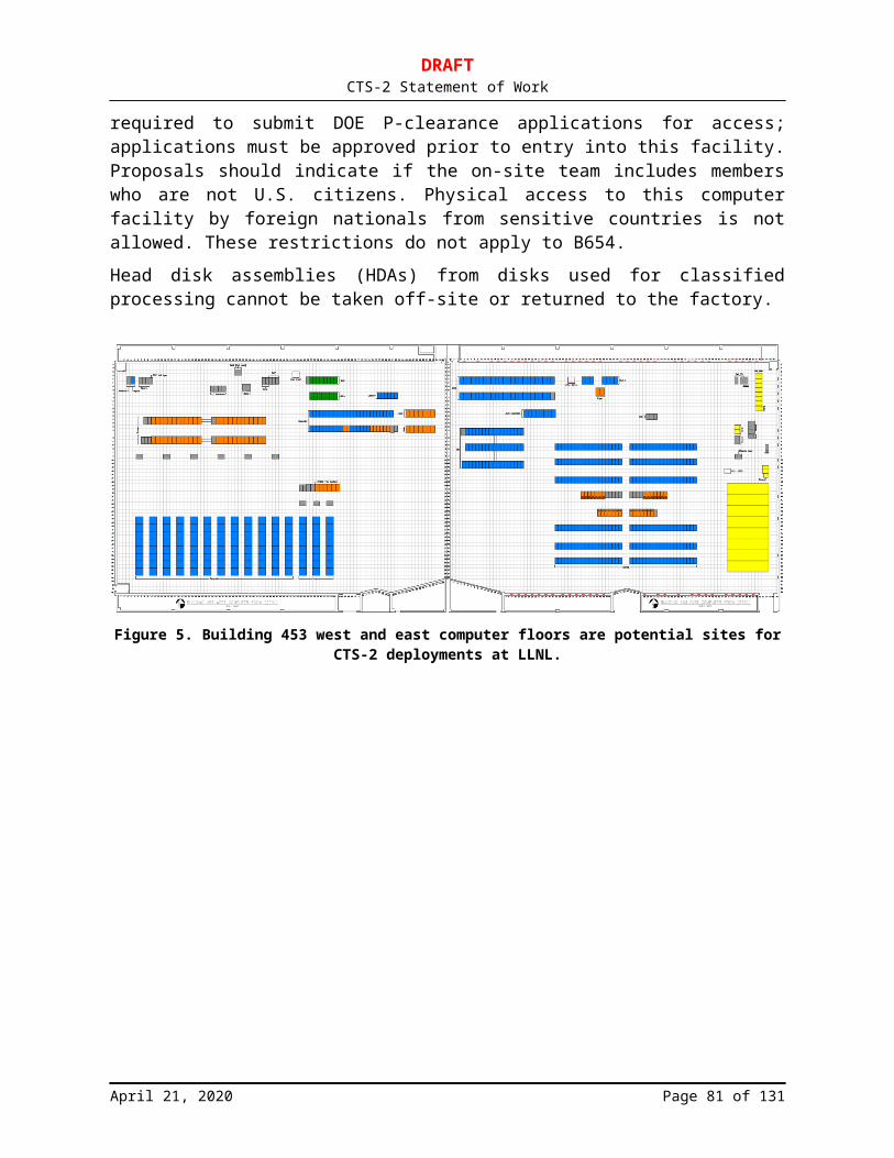
DRAFTCTS-2 Statement of Work
7 Glossary7.1 GeneralLevel 1 Support Initial support level responsible for basic customer issues.Level 2 Support More in-depth support level that involves technical troubleshooting and
problem analysis.Level 3 Support Expert-level trouble shooting and problem analysis.
7.2 Hardwareb Bit. A single, indivisible binary unit of electronic information.B Byte. A collection of eight (8) bits.32b floating-point arithmetic
Executable binaries (user applications) with 32b (4B) floating-point number representation and arithmetic. Note that this is independent of the number of bytes (4 or 8) utilized for memory reference addressing.
32b virtual memory addressing
All virtual memory addresses in a user application are 32b (4B) integers. Note that this is independent of the type of floating-point number representation and arithmetic.
64b floating-point arithmetic
Executable binaries (user applications) with 64b (8B) floating-point number representation and arithmetic. Note that this is independent of the number of bytes (4 or 8) utilized for memory reference addressing.
64b virtual memory addressing
All virtual memory addresses in a user application are 64b (8B) integers. Note that this is independent of the type of floating-point number representation and arithmetic. Note that all user applications should be compiled, loaded with Offeror-supplied libraries, and executed with 64b virtual memory addressing by default.
CDU Cooling Distribution Unit.Cluster A set of SMPs connected via a scalable network technology. The network
will support high-bandwidth, low-latency message passing. It will also support remote memory referencing.
CPU or core or processor
Central Processing Unit or “core” or processor. A VLSI chip constituting one or more computational core(s) (integer, floating-point, and branch units), registers and memory interface (virtual memory translation, TLB, and bus controller), and associated cache.
FLOP or OP Floating Point OPeration.FLOPS or OPS Plural of FLOP.FLOP/s or OP/s Floating Point OPeration per second.
April 21, 2020 Page 81 of 86
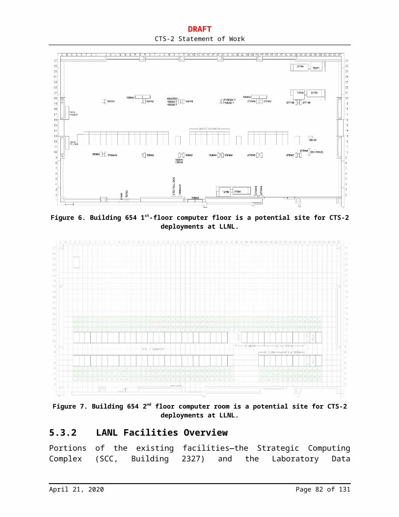
DRAFTCTS-2 Statement of Work
FRU Field Replaceable Unit. An aggregation of parts that is a single unit and can be replaced upon failure in the field.
FSB Front-side bus.GB Gigabyte. One gigabyte is a billion base-10 bytes. This is typically used
in every context except for Random Access Memory size and is 109 (or 1,000,000,000) bytes.
GiB Gibibyte. One gibibyte is a billion base-2 bytes. This is typically used in terms of Random Access Memory and is 230 (or 1,073,741,824) bytes. For a complete description of SI units for prefixing binary multiples, see: http://physics.nist.gov/cuu/Units/binary.html.
GFLOP/s or GOP/s GigaFLOP/s. One billion (109 = 1,000,000,000) 64-bit floating-point operations per second.
HSC Hot Spare Cluster. A set of nodes on-site at LLNL, LANL, or SNL that can be used as a hot-spare pool constructed as a stand-alone cluster. The HSC will be used to run diagnostics on failing nodes (after they are swapped out of CTS-2) to determine the root cause for failures and to potentially test software releases.
HSN High Speed Network. The high-performance cluster network interconnect that connects all nodes in an SU or multi-SU cluster. The HSN supports MPI, file system, and other network traffic critical for HPC applications.
IBA InfiniBand Architecture. See http://www.openfabrics.org and http://www.infinibandta.org
IPMI Intelligent Platform Management Interface. See http://www.intel.com/design/servers/ipmi/
ISA Instruction Set Architecture.MB Megabyte. One megabyte is a million base-10 bytes. This is typically
used in every context except for Random Access Memory size and is 106 (or 1,000,000) bytes.
MiB Mebibyte. One mebibyte is a million base-2 bytes. This is typically used in terms of Random Access Memory and is 220 (or 1,048,576) bytes. For a complete description of SI units for prefixing binary multiples, see: http://physics.nist.gov/cuu/Units/binary.html .
MFLOP/s or MOP/s MegaFLOP/s. One million (106 = 1,000,000) 64-bit floating-point operations per second.
MTBF Mean Time Between Failure. A measurement of the expected reliability of the system or component. The MTBF figure can be developed as the result of intensive testing, based on actual product experience, or predicted by analyzing known factors. See: http://www.t-cubed.com/faq_mtbf.htm.
Node Multi-socket SMP configuration with the Linux operating system and HSN NIC.
April 21, 2020 Page 82 of 86
DRAFTCTS-2 Statement of Work
PCIe4 x16 The PCIe Gen 4 standard with 16 lanes of electrically live links. It is not acceptable to have an x16 slot with an x8 electrical connection.
PDU Power Distribution Unit. The mechanism by which power is distributed to nodes from the higher-amperage wall panel.
Peak Rate The maximum number of 64-bit floating-point instructions (add, subtract, multiply, or divide) per second that could conceivably be retired by the system. For microprocessors, the peak rate is typically calculated as the maximum number of floating-point instructions retired per clock times the clock rate.
POST Power-On Self Test. A set of diagnostics that run when a node is powered on to detect all hardware components and verify correct functioning.
SPC Serial Port Concentrator. A rack-mounted device (that may be combined with the RPC) that connects the serial ports of nodes to the management ethernet via reverse telnet protocol. This allows system administrators to log into the serial port of every node via the management network and perform management actions on the node. In addition, this interface allows the system administrators to set up telnet sessions with each node and log all console traffic.
Scalable A system attribute that increases in performance or size as some function of the peak rating of the system.
SMP Shared memory Multi-Processor. A set of CPUs sharing random access memory within the same memory address space. The CPUs are connected via a high-speed, low-latency mechanism to the set of hierarchical memory components. The memory hierarchy consists of at least processor registers, cache, and memory. The cache will also be hierarchical. If there are multiple caches, they will be kept coherent automatically by the hardware. The main memory will be UMA architecture. The access mechanism to every memory element will be the same from every processor. More specifically, all memory operations are done with load/store instructions issued by the CPU to move data to/from registers from/to the memory.
SU Scalable Unit. This is the (nearly) identical replicate unit of hardware envisioned by this statement of work.
Tera-scale The environment required to fully support production-level, realized teraFLOP/s performance. This environment includes a robust and balanced processor, memory, mass storage, I/O, and communications subsystems; robust code development environment, tools, and operating systems; and an integrated, cluster-wide systems management and full system reliability and availability.
TB Terabyte. One terabyte is a trillion base-10 bytes. This is typically used in every context except for Random Access Memory size and is 1012 (or 1,000,000,000,000) bytes.
April 21, 2020 Page 83 of 86

DRAFTCTS-2 Statement of Work
TCO Total Cost of Ownership. TiB Tebibyte. One tebibyte is a trillion base-2 bytes. This is typically used in
terms of Random Access Memory and is 240 (or 1,099,511,627,776) bytes. For a complete description of SI units for prefixing binary multiples, see: http://physics.nist.gov/cuu/Units/binary.html .
TFLOP/s TeraFLOP/s. One trillion (1012 = 1,000,000,000,000) 64-bit floating-point operations per second.
UMA Uniform Memory Access architecture. The distance in processor clocks between processor registers and every element of main memory is the same. That is, a load/store operation has the same latency, no matter where the target location is in main memory.
7.3 Software32b executable Executable binaries (user applications) with 32b (4B) virtual memory
addressing. Note that this is independent of the number of bytes (4 or 8) utilized for floating-point number representation and arithmetic.
64b executable Executable binaries (user applications) with 64b (8B) virtual memory addressing. Note that this is independent of the number of bytes (4 or 8) utilized for floating-point number representation and arithmetic. Note that all user applications should be compiled, loaded with Offeror-supplied libraries, and executed with 64b virtual memory addressing by default.
API Application Programming Interface. Syntax and semantics for invoking services from within an executing application. All APIs will be available to both Fortran and C programs, although implementation issues (such as whether the Fortran routines are simply wrappers for calling C routines) are up to the supplier.
BIOS Basic Input-Output System. A low-level code (typically assembly language) usually held in flash memory on the node that tests and functions the hardware upon power-up, reset, or reboot and loads the operating system. BIOS also refers to UEFI.
Current standard Term applied when an API is not “frozen” on a particular version of a standard but will be upgraded automatically by the Offeror as new specifications are released. For example, “MPI version 3.0” refers to the standard in effect at the time of writing this document, while “current version of MPI” refers to further versions that take effect during the lifetime of this subcontract.
EDAC Error Detection and Correction. Software based on the BlueSmoke technology; see http://www.sourceforge.net/projects/bluesmoke/
April 21, 2020 Page 84 of 86
DRAFTCTS-2 Statement of Work
Fully supported(as applied to system software and tools)
A product-quality implementation documented and maintained by the HPC machine supplier or an affiliated software supplier.
GFS Government (LLNS) Furnished Software. Software supplied to the Offeror by LLNS when CTS-2 build or installation takes place.
Job A cluster-wide abstraction similar to a POSIX session, with certain characteristics and attributes. Commands will be available to manipulate a job as a single entity (including kill, modify, query characteristics, and query state). The characteristics and attributes required for each session type are as follows:
1) Interactive session: Includes all cluster-wide processes executed as a child (whether direct or indirect through other processes) of a login shell and includes the login shell process as well. Normally, the login shell process will exist in a process chain as follows: init, inetd, [sshd | telnetd | rlogind | xterm | cron], then shell.
2) Batch session: Includes all cluster-wide processes executed as a child (whether direct or indirect through other processes) of a shell process executed as a child process of a batch system shepherd process, and will include the batch system shepherd process as well.
3) FTP session: Includes an ftpd and all its child processes.4) Kernel session: All processes with a pid of 0.5) Idle session: This session does not necessarily actually consist of
identifiable processes. It is a pseudo-session used to report the lack of use of resources.
6) System session: All processes owned by root that are not part of any other session.
MPI Message Passing Interface Version 3.1 or later will be supported. See, for example, http://www-unix.mcs.anl.gov/mpi/mpich/ or http://www.mpi-forum.org/docs/mpi-3.1/mpi31-report.pdf
Published(as applied to APIs)
Where an API is not required to be consistent across platforms, the capability lists it as “published,” meaning that it will be documented and supported although it will be Offeror- or even platform-specific.
Single-point control(as applied to tool interfaces)
Refers to the ability to control or acquire information on all processes/PEs using a single command or operation.
Standard(as applied to APIs)
Where an API is required to be consistent across platforms, the reference standard is named as part of the capability. The implementation will include all routines defined by that standard (even if some simply result in no-ops on a given platform).
April 21, 2020 Page 85 of 86
DRAFTCTS-2 Statement of Work
SWL Synthetic WorkLoad. A set of applications representative of Tri-Laboratory workload used with Gazebo test harness to stress-test the SU and clusters of SU aggregations. The SWL will contain only unclassified codes that are not export controlled.
XXX-compatible(as applied to system software and tool definitions)
Requires that a capability be compatible at the interface level with the referenced standard, although the lower-level implementation details will differ substantially (e.g., “NFSv4-compatible” means that the distributed file system will be capable of handling standard NFSv4 requests, but need not conform to NFSv4 implementation specifics).
-end-
April 21, 2020 Page 86 of 86