aws b1.10m/b1.10:2009 july 1, 2009dl.iran-mavad.com/pdf95/guide for the nondestructive examination...
TRANSCRIPT


550 N.W. LeJeune Road, Miami, FL 33126
AWS B1.10M/B1.10:2009An American National Standard
Approved by theAmerican National Standards Institute
July 1, 2009
Guide for the
Nondestructive Examination of Welds
4th Edition
Supersedes AWS B1.10:1999
Prepared by theAmerican Welding Society (AWS) B1 Committee on Methods of Inspection
Under the Direction of theAWS Technical Activities Committee
Approved by theAWS Board of Directors
Abstract
This guide acquaints the user with the nondestructive examination methods commonly used to examine weldments. Thestandard also addresses which method best detects various types of discontinuities. The methods included are visual,liquid penetrant, magnetic particle, radiographic, ultrasonic, electromagnetic (eddy current), and leak testing.
www.iran-mavad.com مرجع علمى مهندسى مواد

ii
International Standard Book Number: 978-0-87171-757-3American Welding Society
550 N.W. LeJeune Road, Miami, FL 33126© 2009 by American Welding Society
All rights reservedPrinted in the United States of America
Photocopy Rights. No portion of this standard may be reproduced, stored in a retrieval system, or transmitted in anyform, including mechanical, photocopying, recording, or otherwise, without the prior written permission of the copyrightowner.
Authorization to photocopy items for internal, personal, or educational classroom use only or the internal, personal, oreducational classroom use only of specific clients is granted by the American Welding Society provided that the appropriatefee is paid to the Copyright Clearance Center, 222 Rosewood Drive, Danvers, MA 01923, tel: (978) 750-8400; Internet:<www.copyright.com>.
www.iran-mavad.com مرجع علمى مهندسى مواد

vii
Foreword
This foreword is not part of AWS B1.10M/B1.10:2009, Guide for theNondestructive Examination of Welds, but is included for informational purposes only.
The Guide for the Nondestructive Inspection of Welds was first prepared by the AWS B1 Committee on Methods ofInspection in 1977. The next edition was published in 1986, with updates to current industry practices. The 1999 and thiscurrent edition incorporate an overall edit and improvements to the figures.
The purpose of this guide is to give the reader an overview of the more common examination methods available withoutunnecessary detail and to provide an aid in deciding which method is generally best suited for the examination of a givenweld.
The words examination, evaluation, inspection, and testing are considered synonymous when describing various non-destructive examination methods.
This guide has been prepared by the AWS B1 Committee on Methods of Inspection to serve as a simple but reliablesource of general information. It is not intended that this document provide complete and comprehensive coverage of thesubject. There are many reference manuals available. For more comprehensive coverage of the activities of the weldinginspector, this guide should be used in conjunction with the AWS Welding Inspection Handbook, which provides a morethorough description of the duties and responsibilities of welding inspectors, the techniques and characteristics of theusual nondestructive examination methods, and the major aspects of sampling and documentation required for an ade-quate quality control system. For other references on the subject of inspection, refer also to the technical documents sug-gested in Clause 2, Normative References, and Annex E, Informative References. Annex A summarizes the requiredequipment, applications, advantages, and limitations of each of the seven examination methods covered in the document.Annex B is adapted from Part C—Nondestructive Examination Symbols of AWS A2.4:2007, Standard Symbols forWelding, Brazing, and Nondestructive Examination. Annex C provides a list of typical application standards and theaddresses of the standards developers. Annex D provides guidelines for making inquires to AWS committees.
Comments and suggestions for the improvement of this standard are welcome. They should be sent to the Secretary,AWS B1 Committee on Methods of Inspection, American Welding Society, 550 N.W. LeJeune Road, Miami, FL 33126.
www.iran-mavad.com مرجع علمى مهندسى مواد

v
Personnel
*Deceased
AWS B1 Committee on Methods of InspectionC. A. Mankenberg, Chair Shell International Exploration & Production
W. A. Komlos, Vice Chair Arc Tech LLCK. S. Baucher, 2nd Vice Chair Technicon Engineering Services, Incorporated
B. C. McGrath, Secretary American Welding SocietyJ. S. Armstrong LeTourneau Technologies, Incorporated
U. W. Aschemeier H C NuttingB. L. Baker Baker Consulting Company
R. E. Campbell Banker Steel CompanyR. V. Clarke TEAM Industrial Services, IncorporatedL. P. Connor Consultant
R. Cook SME Steel ContractorsH. B. Craft Trinity Industries, Incorporated
D. Crowe Massachusetts Highway DepartmentR. W. Doornink Cantesco Corporation USA
G. L. Goetzmann Spruce Creek ConstructorsG. Gratti Arcos Industries LLC
B. Hill CH2MHILL Construction Canada LTD.R. L. Holdren Applications Technologies Company LLCA. L. Johnson Johnson Inspection and Consulting
E. D. Levert Lockheed Martin Missiles and Fire ControlM. J. Ludwig Cianbro Corporation
R. McCabe AMCA. J. Moore, Jr. Marion Testing & Inspection
G. M. Rogers Arrow Engineering*D. A. Shapira Washington Group International
T. W. Studebaker Terracon ConsultantsD. A Wright Zephyr Products, Incorporated
Advisors to the AWS B1 Committee on Methods of Inspection
C. J. Hellier Hellier AssociatesD. L. Isenhour Northrop Grumman Newport News
C. K. Nicholson MACTEC Engineering & Consulting, IncorporatedC. F. Phelps Joseph Oat Corporation
AWS B1A Subcommittee on Nondestructive Examination of WeldsC. A. Mankenberg, Chair Shell International Exploration & ProductionB. C. McGrath, Secretary American Welding Society
B. L. Baker Bechtel National, IncorporatedK. S. Baucher Technicon Engineering Services, Incorporated
D. Crowe Massachusetts Highway DepartmentW. A. Komlos Arc Tech LLC
www.iran-mavad.com مرجع علمى مهندسى مواد

ix
Table of ContentsPage No.
Personnel ......................................................................................................................................................................vForeword .....................................................................................................................................................................viiList of Tables................................................................................................................................................................xiList of Figures ..............................................................................................................................................................xi
1. General .................................................................................................................................................................11.1 Scope............................................................................................................................................................11.2 Advantages and Limitations of the Examination Method ...........................................................................11.3 Acceptance Standards..................................................................................................................................11.4 Cost ..............................................................................................................................................................11.5 Procedures....................................................................................................................................................21.6 NDE Symbols ..............................................................................................................................................21.7 Safety and Health.........................................................................................................................................21.8 Standard Units of Measurement ..................................................................................................................2
2. Normative References .........................................................................................................................................2
3. Terms and Definitions .........................................................................................................................................2
4. Discontinuities......................................................................................................................................................24.1 Discussion of Discontinuities ......................................................................................................................24.2 List of Discontinuities .................................................................................................................................34.3 Porosity ........................................................................................................................................................44.4 Inclusions.....................................................................................................................................................64.5 Incomplete Fusion .......................................................................................................................................84.6 Incomplete Joint Penetration .......................................................................................................................84.7 Undercut ......................................................................................................................................................84.8 Underfill.......................................................................................................................................................94.9 Overlap ........................................................................................................................................................94.10 Lamination...................................................................................................................................................94.11 Delamination..............................................................................................................................................104.12 Seams or Laps............................................................................................................................................104.13 Lamellar Tear.............................................................................................................................................114.14 Cracks ........................................................................................................................................................114.15 Concavity ...................................................................................................................................................144.16 Convexity ...................................................................................................................................................144.17 Weld Reinforcement ..................................................................................................................................14
5. Nondestructive Examination Methods ............................................................................................................155.l Visual (VT) ................................................................................................................................................155.2 Liquid Penetrant (PT) ................................................................................................................................165.3 Magnetic Particle (MT) .............................................................................................................................185.4 Radiographic (RT) .....................................................................................................................................205.5 Ultrasonic (UT)..........................................................................................................................................245.6 Electromagnetic (ET).................................................................................................................................295.7 Leak (LT) ...................................................................................................................................................31
6. Interrelationships Among Welding Processes, Discontinuities, and Examination Methods ......................32
www.iran-mavad.com مرجع علمى مهندسى مواد

x
Page No.
Annex A (Informative)—Examination Method Selection Guide...............................................................................35Annex B (Informative)—NDE Symbols and Abbreviations......................................................................................37Annex C (Informative)—Typical Industry Standards ................................................................................................45Annex D (Informative)—Guidelines for the Preparation of Technical Inquiries.......................................................47Annex E (Informative)—Informative References ......................................................................................................49
www.iran-mavad.com مرجع علمى مهندسى مواد

1
1. General1.1 Scope. This standard provides a reference guide for the kinds of nondestructive examination methods that are used toverify that welds meet the requirements of a code or specification. The nondestructive examination methods described are:
(1) Visual (VT)
(2) Liquid Penetrant (PT)
(3) Magnetic Particle (MT)
(4) Radiographic (RT)
(5) Ultrasonic (UT)
(6) Electromagnetic (Eddy Current) (ET)
(7) Leak (LT)
The types of discontinuities detected with each method are disclosed and their causes discussed. Acceptance criteria arenot addressed in this standard. Requirements for nondestructive examination and acceptance criteria should be specifiedin procurement documents prior to the award of contracts.
Nondestructive examination (NDE) is a general term used in this text to identify the common examination methods usedfor evaluation of welds and related materials without destroying their usefulness.
Principal factors to consider when choosing an examination method are the advantages and limitations of the method,anticipated type and size of discontinuity, acceptance standards, and cost. Annex A is a guide to process selection.
AWS has chosen nondestructive examination (NDE) as the preferred terminology for these inspection methods. In otherstandards, literature, and industry usage, other expressions are commonly used. Among these are: nondestructive evaluation(NDE), nondestructive inspection (NDI), and nondestructive testing (NDT). It must be emphasized that all of theseexpressions are commonly used and may be considered equivalent.
1.2 Advantages and Limitations of the Examination Method. The advantages and limitations of the examinationmethod help to determine which method(s) is (are) best for detecting discontinuities of a particular size, shape, andorientation. For example, radiography can detect discontinuities with major planes aligned parallel with the radiationbeam, such as cracks oriented normal to material surfaces. Radiography, however, usually cannot detect laminations inmaterial or cracks oriented parallel to the plate surface. Conversely, ultrasonic examination can detect cracks oriented inany direction provided the sound beam is oriented essentially perpendicular to the major axis of the crack.
1.3 Acceptance Standards. The statement “the weld shall be radiographically examined” is incomplete unless accep-tance standards are specified. Acceptance standards define characteristics of discontinuities and state whether particulartypes of discontinuities are allowed. Certain discontinuities such as slag or porosity may be acceptable providing theirsize and distribution are within specified limits. These criteria have to be incorporated in the acceptance standards. Mostcodes and specifications such as AWS D1.1, Structural Welding Code—Steel, ASME Boiler and Pressure Code, and API1104, Welding of Pipeline and Related Facilities, contain acceptance standards. These and other construction standardsare shown in Annex C.
1.4 Cost. Costs of the various examination methods depend on the particular situation. Two factors that should be con-sidered in selection of a nondestructive examination method are the cost of performing the examination and the equipment.
Guide for the Nondestructive Examination of Welds
www.iran-mavad.com مرجع علمى مهندسى مواد

2
Visual examination is usually the least expensive, but it is limited to the detection of surface discontinuities. In general,the cost of radiographic, ultrasonic, or eddy current examination is higher than that of visual, magnetic particle, or liquidpenetrant examination. To meet the intended purpose and minimize cost, qualified personnel should be consulted.
1.5 Procedures. It should be recognized that all NDE methods must be performed in accordance with an approved pro-cedure which is available to the technician performing the test or examination. This is almost always a requirement ofthe application code. Only by following a documented (written) procedure can the NDE technician ensure adherence tocodes and specifications applicable to the fabrication under test. These procedures should be documented to provide alldetails of test preparation, performance, and interpretation to ensure reliability and reproducibility of results.
1.6 NDE Symbols. The use of NDE symbols and abbreviations is shown in Annex B, which is adapted from AWS A2.4,Standard Symbols for Welding, Brazing, and Nondestructive Examination.
1.7 Safety and Health. Safety and health issues and concerns are beyond the scope of this standard and therefore are notfully addressed herein. Safety and health information is available from other sources, including, but not limited to, ANSIZ49.1, Safety in Welding, Cutting, and Allied Processes, and applicable federal and state regulations.
1.8 Standard Units of Measurement. This standard makes use of both the International System of Units (SI) and U.S.Customary Units. The latter are shown within brackets ([ ]) or in appropriate columns in tables and figures. The measure-ments may not be exact equivalents; therefore, each system must be used independently.
2. Normative ReferencesThe following standards contain provisions which, through reference in this text, constitute mandatory provisions of thisAWS standard. For undated references, the latest edition of the referenced standard shall apply. For dated references,subsequent amendments to, or revisions of, any of these publications do not apply.
AWS documents:1
(1) AWS A2.4, Standard Symbols for Welding, Brazing, and Nondestructive Examination.
(2) AWS A3.0, Standard Welding Terms and Definitions.
ANSI documents:2
ANSI Z49.1, Safety in Welding, Cutting, and Allied Processes
3. Terms and DefinitionsThe terminology used in this guide is that established in AWS A3.0, Standard Welding Terms and Definitions. That docu-ment defines a discontinuity as “an interruption of the typical structure of a material, such as a lack of homogeneity in themechanical, metallurgical, or physical characteristics. A discontinuity is not necessarily a defect.” A3.0 defines a defectas “a discontinuity or discontinuities that by nature or accumulated effect render a part or product unable to meet mini-mum applicable acceptance standards or specifications. The term designates rejectability.” For the purpose of this guide,reference will be made to detection of discontinuities without regard to the distinction between acceptance or rejection.
4. Discontinuities4.1 Discussion of Discontinuities. This guide is concerned only with discontinuities, which may be classified as defects(rejectable) depending on acceptance criteria in a particular specification or code. Discontinuities are rejectable only ifthey exceed that allowed by the specification.
Discontinuities may be found in the weld metal, heat-affected, and base metal zones of weldments made in the five basicweld joint types: butt, T-, corner, lap, and edge. The following subclause presents a partial list of discontinuities that maybe encountered in the fabrication of metals by welding. When specific discontinuities are located in the weld metal, heat-affected, or base metal zones, the abbreviations WMZ, HAZ, and BMZ, respectively, are used to indicate the location.
1 AWS standards are published by the American Welding Society, 550 N.W. LeJeune Road, Miami, FL 33126.2 ANSI Z49.1 is published by the American Welding Society, 550 N.W. LeJeune Road, Miami, FL 33126.
www.iran-mavad.com مرجع علمى مهندسى مواد

3
4.2 List of Discontinuities. The most common types of discontinuities in butt, T-, corner, lap, and edge joints are listedin Table 1 and depicted in Figures 1 through 10. Where the list indicates that the discontinuity is generally located in theweld, it may be expected to appear in almost any type of weld. Tungsten inclusions are an exception. Tungsten inclusionsare found only in welds made by the gas tungsten arc or plasma arc welding processes.
Weld and base metal discontinuities of specific types are more common when certain welding processes and joint detailsare used (see Table 2). High restraint and limited access to portions of a weld joint may cause a higher than normal inci-dence of weld and base metal discontinuities. Each general type of discontinuity is discussed in detail in this clause.
Table 1Common Types of Discontinuities
Type of Discontinuity Subclause Location Remarks
(1) Porosity(a) Scattered(b) Cluster(c) Piping(d) Aligned(e) Elongated
4.34.3.14.3.24.3.34.3.44.3.5
WMZ Porosity could also be found in the BM and HAZ if the base metal is a casting.
(2) Inclusion(a) Slag(b) Tungsten
4.44.4.14.4.2
WMZ, WI
(3) Incomplete fusion 4.5 WMZ/WI Fusion face or between adjoining weld beads.
(4) Incomplete joint penetration 4.6 BMZ Weld root in a groove weld.
(5) Undercut 4.7 WI/HAZ Adjacent to weld toe or weld root in base metal.
(6) Underfill 4.8 WMZ Weld face or root surface of a groove weld.
(7) Overlap 4.9 WMZ Weld toe or root surface.
(8) Lamination 4.10 BMZ Base metal, generally near midthickness of section.
(9) Delamination 4.11 BMZ Base metal, generally near midthickness of section.
(10) Seam and lap 4.12 BMZ Base metal surface generally aligned with rolling direction.
(11) Lamellar tear 4.13 BMZ Base metal, near HAZ.
(12) Crack (includes hot cracks and cold cracks described in text)(a) Longitudinal(b) Transverse(c) Crater(d) Throat(e) Toe(f) Root(g) Underbead and HAZ
4.144.14.14.14.2, 4.14.34.14.2, 4.14.44.14.54.14.64.14.74.14.84.14.9
WMZ, HAZ, BMZWMZ, HAZ, BMZWMZWMZWI, HAZWMZHAZ
Weld metal or base metal adjacent to WI.Weld metal (may propagate into HAZ and base metal).Weld metal at point where arc is terminated.Parallel to weld axis. Through the throat of a fillet weld.
Root surface or weld root.
(13) Concavity 4.15 WMZ Weld face of a fillet weld.
(14) Convexity 4.16 WMZ Weld face of a fillet weld.
(15) Weld reinforcement 4.17 WMZ Weld face or root surface of a groove weld.
(16) Spatter WMZ, BMZ Weld face or base metal surface.
(17) Arc strike WMZ, BMZ Weld face or base metal surface.
Legend:WMZ—weld metal zoneBMZ—base metal zoneHAZ—heat-affected zoneWI—weld interface
www.iran-mavad.com مرجع علمى مهندسى مواد

4
4.3 Porosity [see Table 1 (1)3]. Porosity is a cavity type discontinuity formed by gas entrapment during solidification orin a thermal spray deposit. The discontinuity formed is generally spherical, but it may be elongated. A common cause ofporosity is contamination during welding. Generally, porosity is not considered to be as detrimental as other discontinu-ities, such as cracks or incomplete fusion. The rounded shape of porosity does not concentrate stress as much as sharpdiscontinuities like cracks or incomplete fusion. Porosity is an indication that the welding parameters, welding consumables,or joint fit-up are not being properly controlled for the welding process selected or that the base metal is contaminated orof a composition incompatible with the weld filler metal being used. Important information regarding the cause of theproblem is provided by describing both the shape and orientation of individual pores or geometric array of adjacentpores.
An example of this utility is the distinction between elongated porosity and piping porosity. Both have lengths greaterthan their width, but they differ because of their orientation with respect to the weld axis. They also differ in terms ofhow they are caused.
3 The numbers in parentheses in 4.3 through 4.17 refer to numbers in Table 1 and Figures 1 through 10.
Figure 1—Double-V-Groove Weld in Butt Joint
www.iran-mavad.com مرجع علمى مهندسى مواد

5
By providing this additional detail, an inspector is giving more information than a standard will normally require, but itcan be very helpful in determining what corrective action to take.
4.3.1 Scattered Porosity [see Table 1 (1)(a)] is porosity uniformly distributed throughout the weld metal. Whenscattered porosity is encountered, the cause is generally faulty welding techniques or materials. The joint preparationtechnique or materials used may also result in conditions that cause scattered porosity.
If a weld solidifies slowly enough to allow most of the gas to pass to the surface before weld solidification, there will befew pores in the weld.
4.3.2 Cluster Porosity [see Table 1 (1)(b)] is a localized array of porosity having a random geometric distribution. Itoften results from improper welding parameters, techniques, or consumables.
4.3.3 Piping Porosity [see Table 1 (1)(c)] is a form of porosity having a length greater than its width that lies approx-imately perpendicular to the weld face. Piping porosity may also be referred to as wormhole porosity. Piping porosity infillet welds extends from the weld root toward the weld surface. Much of the piping porosity found in welds does notextend all the way to the surface. Careful excavation may also reveal subsurface porosity.
4.3.4 Aligned Porosity [see Table 1 (1)(d)] is a localized array of porosity oriented in a line. The pores may be sphericalor elongated. It often occurs along a weld interface, the interface of weld beads, or near the weld root, and is caused bycontamination that leads to gas evolution at those locations. Aligned porosity is sometimes referred to as linear porosity.
Figure 2—Single-Bevel-Groove and Fillet Welds in Corner Joint
www.iran-mavad.com مرجع علمى مهندسى مواد

6
4.3.5 Elongated Porosity [see Table 1 (1)(e)] is a form of porosity having a length greater than its width that liesapproximately parallel to the weld axis.
4.4 Inclusions [see Table 1 (2)] are entrapped foreign solid material, such as slag, flux, tungsten, or oxide.
4.4.1 Slag Inclusions [see Table 1 (2)(a)] are discontinuities resulting from the entrapment of nonmetallic productswithin the weld metal. Slag inclusions result from the mutual dissolution of flux and nonmetallic impurities in somewelding or brazing processes.
Slag inclusions can be found in welds made with any arc welding process that employs flux as a shielding medium. Ingeneral, slag inclusions result from improper welding techniques, the lack of adequate access for welding the joint, orimproper cleaning of the weld between passes. Due to its relatively low density and melting point, molten slag willnormally flow to the surface of the weld pass. Sharp notches in the weld interface or between passes often cause slag tobe entrapped under the molten weld metal. The release of slag from the molten metal will be expedited by any factor thattends to make the metal less viscous or retard its solidification, such as high heat input.
4.4.2 Tungsten Inclusions [see Table 1 (2)(b)] are tungsten particles trapped in weld metal. Tungsten inclusions areoften associated with the gas tungsten arc welding process and are sometimes associated with the plasma arc weldingprocess. In these processes, a nonconsumable tungsten electrode is used to establish and maintain a welding arc betweenthe electrode and the weld or base metal. If the tungsten electrode is dipped into the molten metal, becomes contami-
Figure 3—Double-Bevel-Groove Weld in T-Joint
www.iran-mavad.com مرجع علمى مهندسى مواد

7
Figure 4—Double Fillet Weld in Lap Joint
Figure 5—Single Pass Double Fillet Weld in T-Joint
www.iran-mavad.com مرجع علمى مهندسى مواد

8
nated or embrittled, or if the current is set too high so as to deposit tungsten droplets, tungsten inclusions may result.Tungsten inclusions appear as light indications on radiographs because tungsten is more dense than steel or aluminumand absorbs more of the radiation.
4.5 Incomplete Fusion [see Table 1 (3)] is a weld discontinuity in which fusion did not occur between weld metal andfusion faces or adjoining weld beads. It is the result of improper welding techniques, improper preparation of the basemetal, or improper joint design.
4.6 Incomplete Joint Penetration [see Table 1 (4)] is a joint root condition in a groove weld in which weld metal doesnot extend through the joint thickness. The unpenetrated and unfused area is a discontinuity described as incompletejoint penetration. Incomplete joint penetration may result from insufficient welding heat, improper joint design (e.g.,thickness the welding arc cannot penetrate), or improper lateral control of the welding arc.
Some welding processes have much greater penetrating ability than others. For joints welded from both sides, backgoug-ing may be specified before welding the other side to ensure that there is no incomplete joint penetration. Pipe welds areespecially vulnerable to this type of discontinuity, since the inside of the pipe is usually inaccessible. Designers mayemploy a backing ring or consumable inserts to aid welders in such cases. Welds that are required to have complete jointpenetration may require examination by visual and some other nondestructive examination method.
4.7 Undercut [see Table 1 (5)] is a groove melted into the base metal adjacent to the weld toe or weld root and leftunfilled by weld metal. This groove creates a mechanical notch which is a stress concentrator. When undercut is con-trolled within the limits of specifications it is not considered a weld defect. Undercut is generally associated with eitherimproper welding techniques or excessive welding currents, or both.
Figure 6—Single-Bevel-Groove Weld in Butt Joint
www.iran-mavad.com مرجع علمى مهندسى مواد

9
4.8 Underfill [see Table 1 (6)] is a condition in which the weld face or root surface of a groove weld extends below theadjacent surface of the base metal. It results from the failure of the welder to completely fill the weld joint.
4.9 Overlap [see Table 1 (7)] is the protrusion of unfused weld metal beyond the weld toe or weld root. Overlap is a sur-face discontinuity that forms a mechanical notch and is nearly always considered rejectable. Two common causes ofoverlap may be insufficient travel speed for the given electrical parameters and improper preparation of the base metal.
4.10 Lamination [see Table 1 (8)] is a type of base metal discontinuity with separation or weakness generally alignedparallel to the worked surface of a rolled product. Laminations may be completely internal and are usually detected non-destructively by ultrasonic examination. They may also extend to an edge or end, where they are visible at the surfaceand may be detected by visual, liquid penetrant, or magnetic particle examination. They may be found when cutting ormachining exposes internal laminations.
Laminations are formed when gas voids, shrinkage cavities, or nonmetallic inclusions in the original ingot are rolled flat.They generally run parallel to the surface of rolled products and are most commonly found in shapes and plates. Metalscontaining laminations cannot be relied upon to carry tensile stress in the through-thickness direction.
Figure 7—Fillet Weld Terminology
www.iran-mavad.com مرجع علمى مهندسى مواد

10
4.11 Delamination [see Table 1 (9)] is a lamination that has separated under stress.
4.12 Seams or Laps [see Table 1 (10)] are base metal discontinuities that may be found in rolled, drawn, and forgedproducts. They differ from laminations in that they appear on the surface of the worked product. When the discontinuityis parallel to the principal stress, it is not generally a critical defect. When seams and laps are perpendicular to theapplied or residual stresses, they will often propagate as cracks. While seams and laps are surface discontinuities, theirpresence may be masked by manufacturing processes that have subsequently modified the surface of the mill product.Welding over seams and laps can cause cracking or porosity.
Figure 8—Fillet Weld Discontinuities
www.iran-mavad.com مرجع علمى مهندسى مواد

11
4.13 Lamellar Tear [see Table 1 (11)] is a subsurface terraced and step-like crack in the base metal with a basic orien-tation parallel to the wrought surface. It is caused by tensile stresses in the through-thickness direction of base metalsweakened by the presence of small, dispersed, planar shaped, nonmetallic inclusions which are parallel to the metal surface.Lamellar tearing most often occurs in heavy section materials.
Lamellar tearing may extend over long distances and generally initiates in regions of the base metal that have a high inci-dence of stringer-like, nonmetallic inclusions in parallel planes and high residual stress. The fracture usually propagatesfrom one lamellar plane to another by shear along lines that are near normal to the rolled surface.
4.14 Cracks [see Table 1 (12)] are defined as fracture type discontinuities characterized by a sharp tip and high ratio oflength and width to opening displacement. They can occur in the weld metal zone, heat-affected zone, and base metalwhen localized stresses exceed the ultimate strength of the material. Cracking often initiates at stress concentrationscaused by other discontinuities or near mechanical notches associated with the weldment design. Stresses that causecracking may be either residual or service induced. Residual stresses may pre-exist in base metals or be fabrication-induced.
A crack formed in a layer of a weld and not completely removed before the next layer is deposited tends to progress intothe layer above and then each succeeding layer until finally; it may appear at the surface. The final extension to the surfacemay occur during cooling after welding has been completed.
4.14.1 Crack Types. Cracks can generally be classified as either hot cracks or cold cracks. Hot cracks occur in ametal during solidification or at elevated temperatures. Hot cracks can occur in both heat-affected (HAZ) and weld metalzones (WMZ) and are the result of insufficient ductility at high temperature. Hot cracks propagate between grains in theweld metal zone or at the weld interface.
Cold cracks occur in a metal at or near ambient temperatures. Cold cracks can occur in base metal (BMZ), heat-affected(HAZ), and weld metal zones (WMZ). They may result from improper welding practices or service conditions. Coldcracks propagate both between grains and through grains.
Figure 9—Groove Weld Terminology
www.iran-mavad.com مرجع علمى مهندسى مواد

12
Figure 10—Groove Weld Discontinuities
www.iran-mavad.com مرجع علمى مهندسى مواد

13
Table 2Discontinuities Commonly Encountered with Welding Processes
Welding Process Porosity SlagIncomplete
Fusion
IncompleteJoint
Penetration Undercut Overlap Cracks
Arc
SW—Stud weldingPAW—Plasma arc weldingSAW—Submerged arc weldingGTAW—Gas arc tungsten weldingEGW—Electrogas welding
XXXXX
X
XXXXX
XXXX
XXXXX
X
X
XXXXX
GMAW—Gas metal arc weldingFCAW—Flux cored arc weldingSMAW—Shielded metal arc weldingCAW—Carbon arc welding
XXXX
XXX
XXXX
XXXX
XXXX
XXXX
XXXX
Resistance
RSW—Resistance spot weldingRSEW—Resistance seam weldingPW—Projection welding
aXa
aXaXXX
XXX
XXX
FW—Flash weldingUW—Upset welding
XX
XX
XX
Oxyfuel Gas
OAW—Oxyacetylene weldingOHW—Oxyhydrogen weldingPGW—Pressure gas welding
XXX
XXX
XX
XX
XX
XXX
Solid-Stateb
CW—Cold weldingDFW—Diffusion weldingEXW—Explosion welding
XXX
XX
FOW—Forge weldingFRW—Friction weldingUSW—Ultrasonic welding
XXX
Other
EBW—Electron beam weldingESW—Electroslag weldingIW—Induction welding
XX X
XXX
XX X X
XXX
LBW—Laser beam weldingPEW—Percussion weldingTW—Thermite welding
X
X X
XXX
X XXX
a Porosity in resistance welds is more properly called voids.b Solid-state is not a fusion process, so incomplete joining is incomplete welding rather than incomplete fusion.
www.iran-mavad.com مرجع علمى مهندسى مواد

14
4.14.2 Crack Orientation. Cracks may be described as either longitudinal [see Table 1 (12)(a)] or transverse [seeTable 1 (12)(b)], depending on their orientation. When a crack is parallel to the weld axis it is called a longitudinal crackregardless of whether it is a centerline crack in weld metal or a toe crack in the heat-affected zone of the base metal.Transverse cracks are perpendicular to the axis of the weld. These may be limited in size and contained completelywithin the weld metal or they may propagate from the weld metal into the adjacent heat-affected zone and further intothe base metal. In some weldments, transverse cracks will form in the heat-affected zone and not in the weld.
4.14.3 Longitudinal Cracks [see Table 1 (12)(a)]. Longitudinal cracks in small welds between heavy sections areoften the result of high cooling rates and high restraint. In submerged arc welding they are commonly associated withhigh welding speeds or may be related to porosity problems that do not appear at the surface of the weld.
4.14.4 Transverse Cracks [see Table 1 (12)(b)] are generally the result of longitudinal shrinkage stresses acting onweld metal of low ductility. Weld metal hydrogen cracking can be oriented in the transverse direction.
4.14.5 Crater Cracks [see Table 1 (12)(c)] occur in the crater of a weld when the weld is improperly terminated.They are sometimes referred to as star cracks, though they may have other configurations. Crater cracks are hot cracksusually forming a pronged star-like network. Crater cracks are found most frequently in materials with high coefficientsof thermal expansion, for example austenitic stainless steel and aluminum. However, the occurrence of any such crackscan be minimized or prevented by filling the crater to a slightly convex shape prior to terminating the arc.
4.14.6 Throat Cracks [see Table 1 (12)(d)] are longitudinal cracks oriented along the throat of fillet welds. They aregenerally, but not always, hot cracks.
4.14.7 Toe Cracks [see Table 1 (12)(e)] are generally cold cracks. They initiate and propagate from the weld toewhere shrinkage stresses are concentrated. Toe cracks initiate approximately normal to the base metal surface. Thesecracks are generally the result of thermal shrinkage stresses acting on a weld heat-affected zone. Some toe cracks occurbecause the transverse tensile properties of the base metal cannot accommodate the shrinkage stresses that are imposedby welding.
4.14.8 Root Cracks [see Table 1 (12)(f)] are longitudinal cracks at the weld root or in the root surface. They may behot or cold cracks.
4.14.9 Underbead and Heat-Affected Zone Cracks [see Table 1 (12)(g)] are generally cold cracks that form in theheat-affected zone of the base metal. They are generally short, but several may join to form a continuous crack. Under-bead cracks can become a serious problem when three elements are present: (1) hydrogen, (2) a microstructure ofrelatively low ductility, and (3) high residual stress. Underbead and heat-affected zone cracks can be both longitudinaland transverse. They are found at regular intervals under the weld and also outline boundaries in the heat-affected zone,where residual welding stresses are highest.
4.15 Concavity [see Table 1 (13)] is the maximum distance from the face of a concave fillet weld to a line joining theweld toes. It is sometimes called insufficient throat. Concavity is not rejectable unless it creates an undersize weld thatexceeds the limits of the application code. Concave fillet welds must be inspected by using a fillet weld gauge capableof measuring the throat dimension, since that is the limiting dimension in terms of the size of a concave fillet weld. Aconcave profile fillet weld size cannot be correctly measured by the leg size.
4.16 Convexity [see Table 1 (14)]. Convexity is the maximum distance from the face of a convex fillet weld perpendic-ular to a line joining the weld toes. Convexity is not rejectable unless it exceeds the limits of the application code. Theconvexity results in a mechanical notch at the junction of the weld face and the base metal similar to that produced byoverlap. The severity is greater when the convexity is greater.
4.17 Weld Reinforcement [see Table 1 (15)]. In groove welds, weld reinforcement is weld metal in excess of the quan-tity required to fill a joint. Weld reinforcement may be located at either the root or face of a groove weld. Weld reinforce-ment is undesirable when it creates high stress concentrations at the weld toes or weld root similar to convexity. It tendsto establish notches that create stress concentrations. This condition may result from improper welding technique orinsufficient welding current.
www.iran-mavad.com مرجع علمى مهندسى مواد

15
5. Nondestructive Examination MethodsNondestructive examination (NDE) is a general term used in this guide to identify all methods that permit evaluation ofwelds and adjacent areas without destroying their usefulness. The purpose of this chapter is to acquaint the weldinginspector with some of the more commonly used nondestructive examination methods and the fundamental conditionsfor their use. Visual examination is the most common of all nondestructive examinations.
For the purpose of this guide the following basic NDE methods will be discussed:
(1) Visual
(2) Liquid Penetrant
(3) Magnetic Particle
(4) Radiographic
(5) Ultrasonic
(6) Electromagnetic (Eddy Current)
(7) Leak
The salient features of each method are summarized in tables in Annex A. It should be noted that nondestructive exami-nation does not eliminate the need for destructive testing, but rather complements it. It is not uncommon for theacceptance-rejection criteria for nondestructive examination to be developed by destructive testing investigations corre-lated with NDE results. The general knowledge presented in this guide should be of valuable assistance to the reader asit provides an overview of the examination methods without unnecessary detail.
5.1 Visual (VT). The integrity of most welds is verified principally by visual examination. Even for weldments withjoints specified for examination throughout by other nondestructive examination methods, visual examination still con-stitutes an important part of practical quality control. Therefore, visual examination is of the first order of importance.Many codes and other standards require welds to be accepted by visual examination prior to the performance of anyother nondestructive examinations. The most extensively used of any method of nondestructive examination, visualexamination is easy to apply, quick, and often requires no special equipment other than good eyesight and some rela-tively simple and inexpensive tools. An extensive review of visual examination is contained in AWS B1.11, Guide forthe Visual Inspection of Welds.
Despite the many advantages of visual examination, a major disadvantage is the need for an inspector who has consider-able experience and knowledge in many different areas which encompass visual welding examination. The inspectormust be familiar with materials, drawings, codes, specifications, weld procedures, performance qualification, procedurequalification requirements, and workmanship standards, and all aspects of good shop practice. Some codes and specifi-cations require that the welding inspector be qualified and certified by examination.
Certain tools are sometimes necessary for some aspects of visual weld examination. Various measuring scales andgauges are used for checking the dimensions of the welds. There are many different types of fillet weld gauges usedthroughout the world to determine the size of fillet welds. Other gauges can be used to verify root opening, weld rein-forcement, and weld bevel angle. Measuring devices are used to check root openings, clearance dimensions of backingmaterials and alignment and fit-up of the workpieces. Temperature indicators verify preheat and interpass temperature.Borescopes, video scopes, flashlights, and mirrors are used in areas of limited accessibility. Flexible fiberoptic examina-tion systems enable the inspector to perform remote visual examination of some areas that are not accessible for directvisual examination or to rigid borescopes.
5.1.1 Visual Examination and Verification Activities Prior to Welding. Material examination prior to fabricationcan eliminate conditions that tend to cause weld defects. Scabs, seams, and scale may be detected at this time, and platelaminations may be observed on cut edges. Other areas that should be inspected prior to welding are:
(1) Verification of correct materials by check of records
(2) Verification of welding procedure and performance qualification
(3) Verification of specified edge preparation, dimensions, and finish
(4) Verification of alignment and fit-up of workpieces
www.iran-mavad.com مرجع علمى مهندسى مواد

16
(5) Verification of clearance dimensions of backing strips, backing rings, and consumable inserts
(6) Verification of cleanliness and condition of tack welds
(7) Verification of proper preheat, when required
(8) Verification of proper storage and handling of filler material.
5.1.2 Visual Examination and Verification Activities During Welding. Visual examination continues during thefabrication process. Various items that should be checked are the following:
(1) Welding process and site conditions
(2) Welding variables and their conformance with welding procedures
(3) Filler metal
(4) Flux and protective gases
(5) Preheat and interpass temperatures
(6) Weld sequencing for distortion control
(7) Preparation of 1st side weld root before welding 2nd side
(8) Interpass chipping, grinding, or gouging
(9) Examination intervals (either time or sequence)
(10) Proper condition of welding equipment and location of welding leads.
5.1.3 Visual Examination and Verification Activities After Welding. If all preliminary aspects of the inspectionprogram have been performed properly, VT after welding should be little more than a verification that all preceding stepshave been successful. Some items which should be included are:
(1) Dimensional accuracy of the completed weldment
(2) Completion of welding
(3) Size of welds
(4) Contour, reinforcement, and surface finish of welds
(5) Degree of underfill, undercut, and overlap
(6) Weld spatter, crater cracks, impression marking, scratches, gouges, and arc strikes
(7) Handling damage
(8) Completion of postweld heat treatment
(9) Nondestructive examinations and results
(10) Preparation and maintenance of inspection records
Visual welding examination, if used before, during, and after welding, may prevent discontinuities that would otherwiseappear in further nondestructive examination or cause failure in service. All inspections and the results should be docu-mented by the inspector.
5.2 Liquid Penetrant (PT). Liquid penetrant examination is a sensitive method of detecting and locating discontinui-ties, provided the discontinuities are clean and open to the surface. The method employs a penetrating liquid dye whichis applied to the properly cleaned surface to be examined and which enters the discontinuity by capillary action. After asuitable dwell time, the excess penetrant is carefully removed from the surface and the part is dried. A developer is thenapplied which acts as a blotter, drawing the penetrant out of the discontinuity. The penetrant, drawn from an opening onthe surface, indicates the presence and location of a discontinuity. The four basic steps are illustrated in Figure 11.
www.iran-mavad.com مرجع علمى مهندسى مواد

17
There are two basic classifications of the penetrant method, both using a similar principle. One uses a visible dye and theother uses a fluorescent dye which is only visible with exposure to ultraviolet light. Visible penetrant is usually red incolor to provide a contrast against the white developer background. Normal white light is usually sufficient to view anyindications present.
Fluorescent penetrants provide a greenish yellow indication against a dark background when viewed in a darkened areaunder a black (ultraviolet) light source. The fluorescent method is more sensitive than the visible dye method. Penetrantsglow under ultraviolet light, making indications readily apparent to the technician. Manufacturers adjust sensitivity byadding fluorescent particles and brighteners into increasingly tenacious penetrants that resist overcleaning.
There are three different types of penetrants used with both the visible and fluorescent methods classified by how theyare removed from the test surface. These are solvent removable, water washable, and post-emulsifiable.
Solvent removable penetrants are formulated to be removed with a solvent using a hand-wiping technique.
The solvent removable penetrants are very portable and used often for on-site examinations.
Water washable penetrants contain emulsifiers that make the oil-based penetrants soluble in water. This method requiresa source of water, a means of disposing of the rinse, and some means for drying the article.
Post-emulsifiable penetrants are not water soluble. Post-emulsifiable penetrants are formulated such that a separateemulsifier must be used. The use of this emulsifier enables clean water to then be used to rinse the emulsified excesspenetrant from the surface of the test piece. Post-emulsifiable penetrants are used when detection of very minute or wide,shallow discontinuities is desired.
Penetrant examination is widely applicable on ferromagnetic and nonmagnetic materials, but it is particularly useful onnonmagnetic materials such as aluminum, magnesium, and austenitic stainless steel where magnetic particle examina-tion cannot be used. It is also useful for locating cracks or other discontinuities which may cause leaks in containers andpipes.
An interesting example of liquid penetrant testing is filling or brushing the inside of a container with penetrant andchecking the outside for leaks (see 5.7). This procedure detects through-wall discontinuities.
Figure 11—Steps in Penetrant Testing
www.iran-mavad.com مرجع علمى مهندسى مواد

18
Liquid penetrant examination is relatively inexpensive. The process is simple and operators find little difficulty in learn-ing to apply it properly. The success of liquid penetrant examination methods depends on the experience and visual acuityof the inspector. In addition, the examination should be performed in accordance with a written procedure. It should bepointed out that some substances in penetrants can have a deleterious effect on either welds or base metals and can affectthe service life of the weld or application of the product. Penetrants are difficult to remove completely from discontinui-ties, and if corrosive to the material, or otherwise not compatible with the product application, they should be avoided.
There are two common methods of recording a PT indication for evaluation. A photograph may be taken of indicationsproduced by the examination. Another method involves the application of clear plastic tape over the indication. Whenthe tape is lifted off the test surface, the indication will adhere to the tape and may be transferred to the examinationreport for future reference.
5.3 Magnetic Particle (MT). This NDE method is used for locating surface or near surface discontinuities in ferro-magnetic materials. Magnetic particle examination is based on the principle that magnetic lines of force will be distortedby a change in material continuity; i.e., a discontinuity creating a magnetic field or flux leakage (see Figure 12).
A weldment can be magnetized by passing an electric current through the weld area (direct magnetization) or by placingthe weldment in a magnetic field (indirect magnetization).
The direct magnetization method is normally used with direct current (dc), half wave direct current (hwdc) or full wavedirect current (fwdc) (see Figure 13). These types of currents have penetrating abilities that generally enable slightlysubsurface discontinuities to be detected. Direct magnetization may also be used with alternating current (ac), which islimited to the detection of surface discontinuities only. Alternating current is also the method of choice for the locationof service related fatigue discontinuities.
Detection of slightly subsurface discontinuities depends on several variables, including the magnetizing method, the typeof current, the directions and density of the magnetic flux, and the material properties of the weldment. When evaluatingsurface discontinuities only, alternating current (ac) is preferred with the indirect magnetization method (see Figure 14).
The alternating current continuously reverses the polarity (direction) of the magnetic field and causes the magnetic particlesto have greater mobility than is possible with direct current. Particle mobility promotes the detection of weak flux leakagesproduced by small surface breaking discontinuities. However, alternating current has a very low penetrating ability becausethe alternating magnetic field is concentrated at the surface of the metal.
Figure 12—Magnetic Field Leakage
www.iran-mavad.com مرجع علمى مهندسى مواد

19
When the magnetic field has been established within the workpiece, magnetic particles (examination medium) areapplied to the surface to be examined. The magnetic particles can be dry or suspended in a liquid. Discontinuities can befurther enhanced using fluorescent magnetic particles and observing them under black light. After removal of excessparticles, the remaining particles trapped in the leakage field of a discontinuity reveal the location, shape, and size of adetectable discontinuity. These indications usually are distinguishable by their appearance as sharp, well defined lines ofmedium against the background of the weld or heat-affected zone surface.
Magnetic particle examination can be very beneficial as an in-process evaluation technique. Assurance of a sound weldbefore the weld is completed may prevent costly repairs of the final product. In-process magnetic particle examinationhas become more of a common practice due to the portability of modern lightweight equipment. This advantage aids inreducing production time.
Figure 13—Direct Magnetization Using dc Prods
Figure 14—Indirect Magnetization Using a Yoke
www.iran-mavad.com مرجع علمى مهندسى مواد

20
Magnetic particle examination is less expensive than radiographic (RT) or ultrasonic (UT) examination. Magnetic parti-cle examination equipment is relatively low in price compared to the equipment used with RT or UT, and less trainingtime is generally required for personnel to become competent in performing magnetic particle examination and evaluat-ing discontinuities. Using MT, the inspector obtains an instant visible indication of the size and orientation of the discon-tinuity. Compared to PT, the MT method has the advantage of revealing discontinuities that are not open to the surface,and therefore not detectable by PT. Magnetic particle examination is generally faster, requires less surface preparation,and is therefore usually more economical than liquid penetrant examination (neglecting equipment costs).
The MT method is limited to ferromagnetic materials. Welded joints between metals of dissimilar magnetic characteris-tics may create nonrelevant magnetic particle indications even though the welds themselves are sound. Most weld surfacesare acceptable for magnetic particle examination after the removal of slag, or other extraneous material which maymechanically hold the test medium or block the medium from a true discontinuity. Surface preparation requirementsprior to MT are generally addressed in the requirements of the applicable code.
There are two common methods of recording an MT indication for evaluation. A photograph may be taken of indicationsproduced by the examination. Another method involves the application of clear plastic tape over the indication. Whenthe tape is lifted off the test surface, the indication will adhere to the tape and may be transferred to the examinationreport for future reference. These techniques also apply to liquid penetrant examination.
5.4 Radiographic (RT). RT is a method of nondestructive examination that utilizes radiation to penetrate a weld andreveal information about its internal conditions. When a weld is exposed to penetrating radiation, some radiation will beabsorbed, some scattered, and some transmitted through the weld onto a recording device (see Figure 15). Most conven-tional RT techniques used today involve exposures that record a permanent image on a photographic film, although otherimage recording methods are also used.
The basic process of radiographic examination involves two general steps:
(1) the making of the radiograph, and
(2) interpretation of the radiograph.
The essential elements needed to carry out these two operations consist of:
(1) A source of radiation
(2) Weld to be radiographed
(3) Weld identification markers, station markers and image quality indicators (IQI)
(4) An X-ray film enclosed in a light tight film holder
(5) A skilled person capable of producing an exposed film
(6) A means of chemically processing the exposed film
(7) A skilled person capable of interpreting and evaluating the radiographic images
Two types of radiation sources commonly used in weld examination are X-ray machines and radioactive isotopes. X-radiation is produced by machines which range from portable, low energy units capable of radiographing relatively thinobjects, to mammoth linear accelerators and betatrons capable of radiographing thick steel welds up to 500 mm [20 in]thick. Gamma radiation is emitted by radioisotopes, the two most common being Cobalt 60 and Iridium 192. Cobalt 60will effectively penetrate up to approximately 125 mm [5 in] of steel; whereas, Iridium 192 is effectively limited to asteel thickness of about 75 mm [3 in].
The radiographic process is dependent upon varying amounts of radiation being absorbed by different areas of the weld.Two key factors determine the rates of differential absorption: the amount of mass represented by the metal and thepenetrating power (defined by the energy) of the radiation source. The amount of mass is related to the thickness and thedensity or composition of the metal. The penetrating power of the radiation source is dependent upon the instrumentsettings of the X-ray machine or the characteristic energy level and intensity of the particular isotope selected for gammaradiography. The differences in absorption occurring during the exposure process account for the dark and light regionson the radiograph.
Film, another obvious essential element to the radiographic process, consists of a thin transparent plastic base coated withfine crystals of silver bromide (emulsion). The grain size of the silver bromide emulsion determines speed and sensitivity
www.iran-mavad.com مرجع علمى مهندسى مواد

21
of the film. The emulsion is sensitive to radiation just as photographic film is to light. Developing (chemical processing)the film converts the image produced on the film emulsion by exposure to radiation into a visible, permanent image.
The interpretation of a radiograph involves identifying the images resulting from various light and dark regions on thefilm. The dark regions represent the more easily penetrated parts of the weld (i.e., thin sections and most types of discon-tinuities) while the lighter regions represent the more difficult areas to penetrate (i.e., thick sections). Interpretation isusually performed in a room of subdued background lighting by placing the radiograph in front of a relatively brightlight source. The subdued background lighting reduces light reflections off the film surface which may obscure the inter-preter’s view of radiographic images. Figure 16 illustrates several types of weld discontinuities a film interpreter mayencounter in the evaluation of weld radiographs.
Figure 15—Making a Radiograph
www.iran-mavad.com مرجع علمى مهندسى مواد

22
(A)
(D)
Figure 16—Radiographs of Weld Discontinuities and Macrosections
(B)
(E)
(C)
(A) Incomplete penetration is indicatedby a sharp straight line. The line isstraight because it is the original cutedge of the root face.
(B) Incomplete penetration caused bypoor fit of the joint. This condition is oftencalled a hi-low fit.
(C) Transverse weld metal crack. Thiscrack could also be found by visual,magnetic, or penetrant examination.
(D) Porosity. Porosity is indicated bydark oval-shaped images.
(E) Elongated slag inclusion. Radio-graphic image shows that the slag inclu-sion is intermittent.
www.iran-mavad.com مرجع علمى مهندسى مواد

23
A significant limitation of radiography is that discontinuities must be favorably aligned with the radiation beam to bereliably detected. This is usually not a problem for discontinuities such as porosity or slag since they are usually round incross section and align with a beam from any direction. This is not the case with planar discontinuities such as cracks,incomplete fusion, and laminations. A substantial portion of these discontinuities must be favorably aligned with theradiation beam to be reliably detected by the interpreter. Figure 17 illustrates this limitation.
Radiography also has several other limitations:
(1) It presents a potential radiation hazard to both personnel and the public.
(2) The cost of radiographic equipment, facilities, safety programs, and related licensing is relatively high.
(3) There is usually a relatively long time, compared to other methods, between the exposure process and the avail-ability of results.
(4) Accessibility to both sides of the workpiece is required to set-up apparatus.
Compared to other nondestructive examination methods, radiography has the following advantages:
(1) It is generally not restricted by the type of material.
Figure 17—Detection of Planar Discontinuities at Various Orientations by Radiography
www.iran-mavad.com مرجع علمى مهندسى مواد

24
(2) Both surface and subsurface discontinuities may be detected.
(3) Radiographic images aid in characterization (identification) of discontinuities.
(4) It provides a permanent record for future review.
(5) The radiograph may be used to make a map, or transparent overlay, in order to locate the exact defect orientationand assist in the removal of the unacceptable condition in the weldment.
5.5 Ultrasonic (UT). Ultrasonic examination (UT) is one of the most widely used methods of nondestructive examina-tion. Its primary application is the detection and characterization of internal discontinuities. It is also used to detect sur-face discontinuities, to define bond characteristics, and to measure thickness. The pulse-echo method with A-scan datapresentation is most commonly used for examining welds. This system utilizes a cathode ray tube (CRT) or digitalscreen to display examination information. The basic components of the pulse-echo method are shown in block diagramform in Figure 18.
High-frequency sound waves are introduced into the material to detect surface and subsurface discontinuities. The soundwaves travel through the material with some loss of energy (attenuation) and are reflected at interfaces. The reflectedsound beam is detected and analyzed to define the presence and location of discontinuities.
In many respects, a beam of ultrasound is similar to a beam of light; both are waves and obey a general wave equation.Each travels at a characteristic velocity in a given homogeneous medium. The velocity in a given medium depends on
Figure 18—Block Diagram, Pulse-Echo Flaw Detector
www.iran-mavad.com مرجع علمى مهندسى مواد

25
the properties of the medium and the vibrational movement of the wave. Like beams of light, ultrasonic beams arereflected from surfaces (see Figure 19); refracted when they cross a boundary between two substances that have differentcharacteristic sound velocities (see Figure 20); and diffracted at edges or around obstacles (see Figure 21). Scattering byrough surfaces, particles, or coarse grains reduces the energy of an ultrasonic beam, similar to the manner in which scat-tering reduces the intensity of a light beam.
Ultrasonic examination is usually performed with either longitudinal waves (straight beam) or shear waves (angle beam).The most commonly used frequencies are between 1 MHz and 5 MHz, with sound beams at angles of 0°, 45°, 60°, and70° measured from a line perpendicular to the material surface.
Figure 19—Similarities Between Reflections of Light and Sound at Boundaries
Figure 20—Refraction
www.iran-mavad.com مرجع علمى مهندسى مواد

26
In longitudinal beam testing (commonly used to examine plate material), sound in the form of ultrasonic vibrations isintroduced into the part perpendicular (normal) to the entry surface by a straight beam search unit (see Figure 22). Whenthe entry surface and the back surface are parallel, a back reflection will appear on the display screen. A discontinuitylying between the front and back surfaces will also be displayed on the display screen. By measuring the height of thereflection on the display screen, from a real or artificial discontinuity of a known size, a reference level can be estab-lished such that reflections from discontinuities of unknown sizes may be evaluated.
The angle beam technique (see Figure 23) is used for the examination of welds. Ideally, only discontinuities shouldappear on the display screen during angle beam examination (see Figure 24). This is not always the case, however, sincethe geometrical boundaries of the part being examined often reflect sound in the same manner as a discontinuity. There-fore, care must be taken during ultrasonic examination of joints with complex geometries (such as welds with backingbars) to assure that indications are the result of the presence of discontinuities and not simply due to the configuration ofthe joint. Figure 25 illustrates a true discontinuity (slag inclusion) masked by a false indication from the backing bar;however, this discontinuity can be evaluated by examining from the opposite side of the weld if accessible.
It is generally desirable to have the sound beam intercept the plane of the discontinuity at or near 90° so that the maxi-mum amount of sound is reflected to the transducer. However, cracks that are not oriented perpendicular to the ultrasonicbeam can be detected because their surfaces are not smooth and sound is reflected from the facets that are approximatelyperpendicular to the beam. The selection of the test surface for scanning with the search unit depends on accessibility.Scanning surface selection is also based on the weld shape and structure.
The scan pattern must be sufficient to pass the projected sound beam through the entire volume of weld and heat-affectedzone to permit detection of possible discontinuities. This accounts for the wide variety of angle search units available. Inspecial cases, search units are made to specific nonstandard angles.
Since it is important to intercept the discontinuity at or near 90°, it is common for more than one angle search unit to beused to examine a particular weld. For example, AWS D1.1, Structural Welding Code—Steel, specifies angles to be usedfor particular thickness and joint configurations and in some cases more than one angle is required.
The principal advantages of ultrasonic examination, as compared to other methods of nondestructive examination ofmetal parts are:
(1) Allows the detection of discontinuities deep in the part.
(2) High sensitivity permits the detection of very small discontinuities.
Figure 21—Diffraction
www.iran-mavad.com مرجع علمى مهندسى مواد
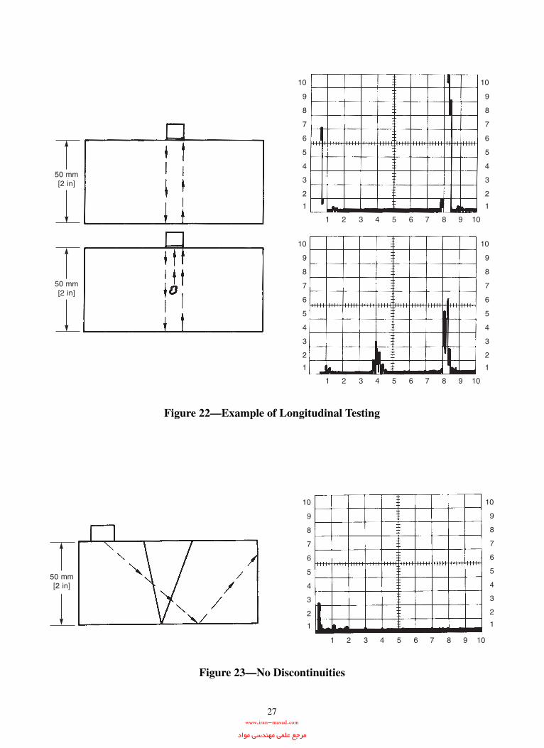
27
Figure 22—Example of Longitudinal Testing
Figure 23—No Discontinuities
www.iran-mavad.com مرجع علمى مهندسى مواد

28
(3) Greater accuracy in determining the position of internal discontinuities, estimating size, and characterizing theorientation, shape, and nature.
(4) Only one surface need be accessible.
(5) Provides almost instantaneous indications of discontinuities. This makes the method suitable for immediate inter-pretation, automation, rapid scanning, production line monitoring, and process control. With some systems, a permanentrecord of examination results can be made for future reference.
(6) Scanning ability enables examination of a volume of metal extending from front to back surface of a weld.
Some disadvantages of ultrasonic examination include:
(1) Requires careful attention by experienced technicians.
(2) Extensive technical knowledge is required for the development of examination procedures and the interpretationof indications.
Figure 24—Discontinuity
Figure 25—Backing Bar False Indication
www.iran-mavad.com مرجع علمى مهندسى مواد

29
(3) Parts that are rough, irregular in shape, very small or thin, or inhomogeneous are difficult to examine.
(4) Discontinuities that are present in a shallow layer immediately beneath the examination surface may not bedetectable.
(5) Couplants are needed to provide effective transfer of ultrasonic-wave energy between search units and the partbeing examined.
(6) Reference standards which duplicate the exact examination conditions may be needed for calibrating the equipment.
(7) Materials with coarse grain structures are difficult to examine.
5.6 Electromagnetic (ET). Electromagnetic (Eddy current) examination (ET) can be defined as an electromagneticnondestructive examination method in which small electrical currents are induced in a material, and any changes in theflow of these currents in the material are detected by a nearby coil for subsequent electronic processing and presentation.Its use for the examination of welds for surface or subsurface discontinuities is only one of the many applications (seeFigure 26). Eddy current techniques have also been successfully applied to measure conductivity, grain size, hardness,and thickness; to identify materials with different composition, microstructure, magnetic permeability, and condition ofheat treatment; and to determine the thickness of coatings and plating on various materials.
In eddy current examinations, an alternating current is passed through a coil placed in proximity to the weld. The alter-nating current in the coil creates an alternating magnetic field in the material. The alternating magnetic field in the weld,in turn, creates electrical currents (eddy currents) in the material. These eddy currents, which vary with the magneticfield, create their own magnetic field which interacts with the initial field. The test coil, or in some cases a separatepickup coil, is electronically monitored to detect any changes in this field interaction. Discontinuities in the weld willalter the magnitude and direction of the eddy currents and thus be detected through the test signal. The signal is thendisplayed on an analog meter, digital meter, cathode ray tube (CRT), X-Y plotter, or strip chart recorder, depending onthe particular equipment and application.
A common coil used for weld examination is shown in Figure 27. Figure 27 shows an encircling coil which is usedprimarily on welded pipe with a longitudinal butt joint. Since the eddy currents flow in a circumferential direction, longi-tudinal discontinuities would produce the most significant change in eddy current flow. Hence, this technique would be
Figure 26—Eddy Current Weld Examination
www.iran-mavad.com مرجع علمى مهندسى مواد

30
most sensitive to longitudinally oriented discontinuities. The pipe is usually passed on rollers through the coil, whichmakes the technique suitable for automation. Their size, windings, and core (if any) vary with the type of material, orien-tation of discontinuities of interest, and size of the smallest discontinuity of interest.
Several types of commonly used surface probes are shown in Figure 28. These probes can be used in any position andare usually hand manipulated.
Several advantages of using eddy current examination on welds include:
(1) The equipment used with surface probes is generally lightweight and portable (see Figure 26).
(2) Some weld surface conditions, such as excessive roughness and minor undercut, may result in irrelevant indica-tions with other NDE methods. Welds with such conditions can usually be examined by eddy current techniques withoutthe need to verify the indication’s relevance by further processing (i.e., grinding to remove the surface irregularity andretesting).
(3) Intimate contact between the weld metal and probe is not required, therefore painted or coated welds can beexamined. This will also allow for the examination of hot surfaces and result in significant savings in the areas of in-service examinations and periodic preventive maintenance examinations.
(4) In some instances, such as the examination of welded pipe, the process can be partially or completely automatedto facilitate high speed, relatively inexpensive examination.
There are three general limitations in using eddy current examination on welds:
(1) The test article (i.e., weld) must be an electrical conductor.
(2) The depth of examination is generally limited to 6 mm [0.25 in] for nonferromagnetic materials and 0.25 mm[0.01 in] for ferromagnetic materials. The penetration in ferromagnetic materials may be significantly increased by usingspecial techniques such as magnetic saturation of the area being examined.
Figure 27—Encircling Coil for the Eddy Current Examination of Welded Pipe
www.iran-mavad.com مرجع علمى مهندسى مواد
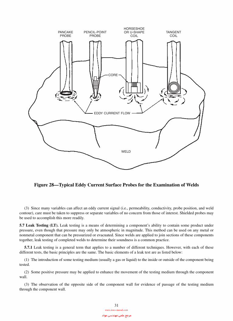
31
(3) Since many variables can affect an eddy current signal (i.e., permeability, conductivity, probe position, and weldcontour), care must be taken to suppress or separate variables of no concern from those of interest. Shielded probes maybe used to accomplish this more readily.
5.7 Leak Testing (LT). Leak testing is a means of determining a component’s ability to contain some product underpressure, even though that pressure may only be atmospheric in magnitude. This method can be used on any metal ornonmetal component that can be pressurized or evacuated. Since welds are applied to join sections of these componentstogether, leak testing of completed welds to determine their soundness is a common practice.
5.7.1 Leak testing is a general term that applies to a number of different techniques. However, with each of thesedifferent tests, the basic principles are the same. The basic elements of a leak test are as listed below:
(1) The introduction of some testing medium (usually a gas or liquid) to the inside or outside of the component beingtested.
(2) Some positive pressure may be applied to enhance the movement of the testing medium through the componentwall.
(3) The observation of the opposite side of the component wall for evidence of passage of the testing mediumthrough the component wall.
Figure 28—Typical Eddy Current Surface Probes for the Examination of Welds
www.iran-mavad.com مرجع علمى مهندسى مواد

32
In cases where gases are used, leak test solution or special detection devices may be employed to indicate the presence ofthe gas.
5.7.2 The simplest form of a leak test is where a testing liquid is placed inside the test object. Then the outside of thecomponent is examined for the presence of any liquid that has penetrated through the wall. Filling some storage con-tainer with water and observing the outside of the vessel would be an example of such a leak test.
5.7.3 A variation of this practice would be to apply some additional pressure to increase the mobility of the liquidthrough the component wall. Such is the case when a pressure vessel is subjected to a hydrostatic test, where water isthe testing medium. This pressure may be provided by pumping the liquid at some high pressure or by introducing a gasin addition to the liquid testing medium. In some cases, the testing medium may be totally gaseous, as in the case of apneumatic test, where compressed air is utilized.
5.7.4 In cases where air or some other gas is utilized as the testing medium, its presence on the low pressure side ofthe component may be difficult to observe. To enhance the detection of the test medium, the component may beimmersed in a liquid bath or sprayed with a leak test solution on the outside surface. If the gas has gained passagethrough the component wall, it will create bubbles in the liquid bath or leak test solution which can be easily detectedvisually.
5.7.5 Vacuum box testing is a leak testing variation where the examiner only has access to one side of a component tobe leak tested. Here, a leak test solution is applied to the test area and a rubber-gasketed enclosure with a clear viewingwindow is placed over the area. Using a bypass valve with an air compressor or a vacuum pump, the air is evacuatedfrom the enclosure to produce a difference in pressure across the weld. If a leak exists, bubbles will form in the leak testsolution. This technique is commonly employed for the testing of weld joints in the floors of storage tanks.
5.7.6 One additional type of leak testing to be discussed here utilizes a gas of very small molecular size as the testingmedium. Helium is the most commonly used gas for this purpose. The helium is introduced into the test object underpressure. It is then detected on the opposite side of the component using special instruments such as a mass spectrometerwith extremely sensitive calibrated leak standards. This form of leak testing provides extremely high sensitivity, or theability to detect the smallest of leaks.
6. Interrelationships Among Welding Processes, Discontinuities, and Examination Methods
This clause includes several tables indicating particular relationships existing between welding processes, discontinui-ties, and examination methods. This information is provided as a reference only and should not be considered applicablefor every specific examination situation.
Many factors which are beyond the scope of this guide affect these relationships. For example, Table 2 lists the discon-tinuities for each welding process that may occur under varying conditions and with many combinations of filler andbase metals. When specific welding variables are controlled, depending on the type of filler and base metals, some of thediscontinuities would not be expected to form.
Table 3 relates examination methods to the various types of discontinuities. Other factors also must be considered beforethe examination method may be reliably chosen for consistent results. For example, the shape of the weld, the compati-bility of the material with the chosen method, and the welding process all affect the choice of method.
Table 4 relates joint types to applicable nondestructive examination methods. Again, further information is necessarybefore a preferred method can be chosen. Material type and shape, welding process, criticality level of the weldment,and unacceptable discontinuity types must be considered in selecting the most suitable examination method.
One should not attempt to draw conclusions by comparing one table to another. Each table stands by itself and is onlyprovided as a general guide. If information beyond that presented by this document is needed, the informative referencescited in Annex E should be reviewed, or a competent nondestructive examination consultant should be contacted.
Further information on the applicability of several of the nondestructive examination methods may be found in Annex A.
www.iran-mavad.com مرجع علمى مهندسى مواد
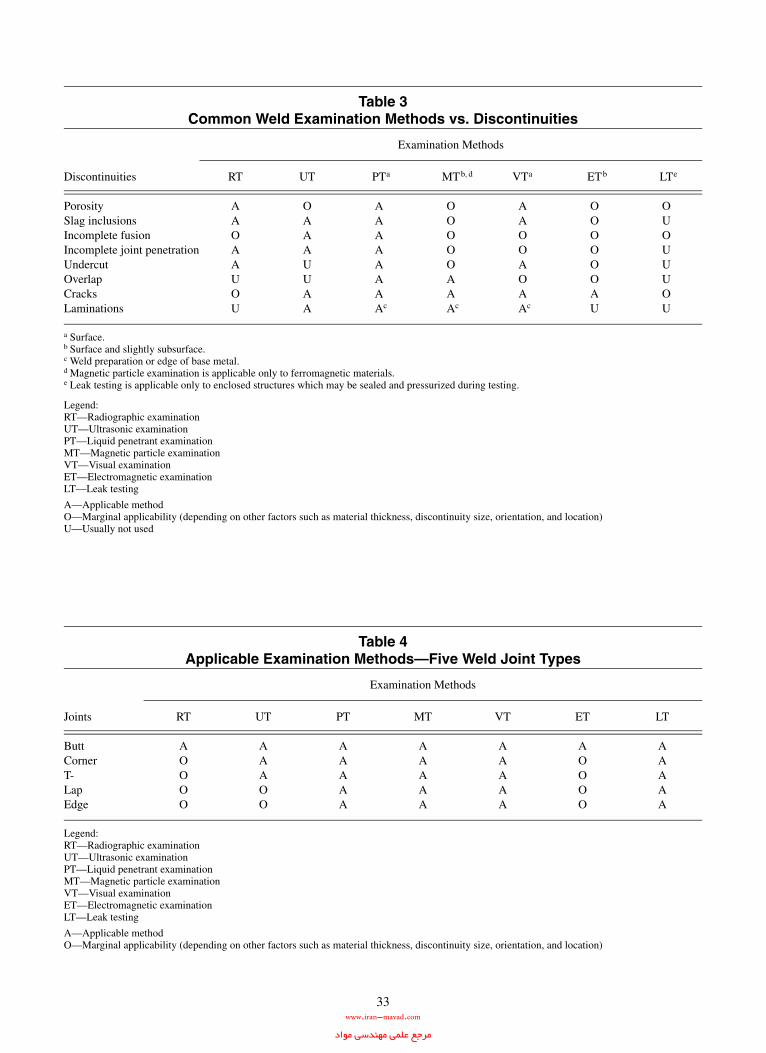
33
Table 3Common Weld Examination Methods vs. Discontinuities
Discontinuities
Examination Methods
RT UT aPTa b, dMTb, d VTa bETb eLTe
PorositySlag inclusionsIncomplete fusionIncomplete joint penetrationUndercutOverlapCracksLaminations
AAOAAUOU
OAAAUUAA
AAAAAAA
cAc
OOOOOAA
cAc
AAOOAOA
cAc
OOOOOOAU
OUOUUUOU
a Surface.b Surface and slightly subsurface.c Weld preparation or edge of base metal.d Magnetic particle examination is applicable only to ferromagnetic materials.e Leak testing is applicable only to enclosed structures which may be sealed and pressurized during testing.
Legend:RT—Radiographic examinationUT—Ultrasonic examinationPT—Liquid penetrant examinationMT—Magnetic particle examinationVT—Visual examinationET—Electromagnetic examinationLT—Leak testing
A—Applicable methodO—Marginal applicability (depending on other factors such as material thickness, discontinuity size, orientation, and location)U—Usually not used
Table 4Applicable Examination Methods—Five Weld Joint Types
Joints
Examination Methods
RT UT PT MT VT ET LT
ButtCornerT-LapEdge
AOOOO
AAAOO
AAAAA
AAAAA
AAAAA
AOOOO
AAAAA
Legend:RT—Radiographic examinationUT—Ultrasonic examinationPT—Liquid penetrant examinationMT—Magnetic particle examinationVT—Visual examinationET—Electromagnetic examinationLT—Leak testing
A—Applicable methodO—Marginal applicability (depending on other factors such as material thickness, discontinuity size, orientation, and location)
www.iran-mavad.com مرجع علمى مهندسى مواد
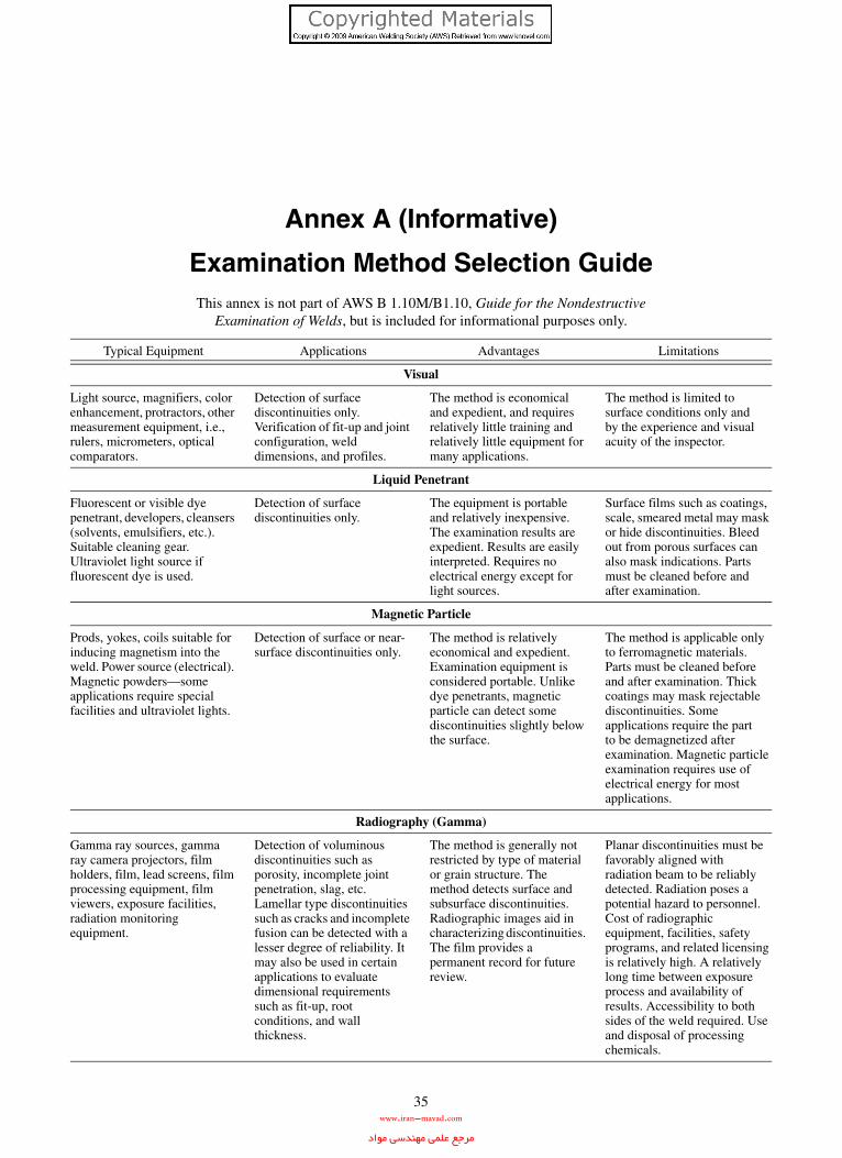
35
Annex A (Informative)
Examination Method Selection GuideThis annex is not part of AWS B 1.10M/B1.10, Guide for the Nondestructive
Examination of Welds, but is included for informational purposes only.
Typical Equipment Applications Advantages Limitations
Visual
Light source, magnifiers, color enhancement, protractors, other measurement equipment, i.e., rulers, micrometers, optical comparators.
Detection of surface discontinuities only. Verification of fit-up and joint configuration, weld dimensions, and profiles.
The method is economical and expedient, and requires relatively little training and relatively little equipment for many applications.
The method is limited to surface conditions only and by the experience and visual acuity of the inspector.
Liquid Penetrant
Fluorescent or visible dye penetrant, developers, cleansers (solvents, emulsifiers, etc.). Suitable cleaning gear. Ultraviolet light source if fluorescent dye is used.
Detection of surface discontinuities only.
The equipment is portable and relatively inexpensive. The examination results are expedient. Results are easily interpreted. Requires no electrical energy except for light sources.
Surface films such as coatings, scale, smeared metal may mask or hide discontinuities. Bleed out from porous surfaces can also mask indications. Parts must be cleaned before and after examination.
Magnetic Particle
Prods, yokes, coils suitable for inducing magnetism into the weld. Power source (electrical). Magnetic powders—some applications require special facilities and ultraviolet lights.
Detection of surface or near-surface discontinuities only.
The method is relatively economical and expedient. Examination equipment is considered portable. Unlike dye penetrants, magnetic particle can detect some discontinuities slightly below the surface.
The method is applicable only to ferromagnetic materials. Parts must be cleaned before and after examination. Thick coatings may mask rejectable discontinuities. Some applications require the part to be demagnetized after examination. Magnetic particle examination requires use of electrical energy for most applications.
Radiography (Gamma)
Gamma ray sources, gamma ray camera projectors, film holders, film, lead screens, film processing equipment, film viewers, exposure facilities, radiation monitoring equipment.
Detection of voluminous discontinuities such as porosity, incomplete joint penetration, slag, etc. Lamellar type discontinuities such as cracks and incomplete fusion can be detected with a lesser degree of reliability. It may also be used in certain applications to evaluate dimensional requirements such as fit-up, root conditions, and wall thickness.
The method is generally not restricted by type of material or grain structure. The method detects surface and subsurface discontinuities. Radiographic images aid in characterizing discontinuities. The film provides a permanent record for future review.
Planar discontinuities must be favorably aligned with radiation beam to be reliably detected. Radiation poses a potential hazard to personnel. Cost of radiographic equipment, facilities, safety programs, and related licensing is relatively high. A relatively long time between exposure process and availability of results. Accessibility to both sides of the weld required. Use and disposal of processing chemicals.
www.iran-mavad.com مرجع علمى مهندسى مواد

36
Radiography (X-rays)
X-ray sources (machines), electrical power source, same general equipment as used with gamma sources (above).
Same application as above. Same as above, except thatX-ray radiography can use adjustable energy levels, and it generally produces higher quality radiographs than gamma sources. The process also enjoys the same advantages as above.
High initial cost of X-ray equipment. Not generally considered portable. Also, same limitations as above.
Ultrasonic
Pulse-echo instrument capable of exciting a piezoelectric material and generating ultrasonic energy within a weld, and a suitable cathode ray tube scope or digital display capable of displaying the magnitudes of received sound energy. Calibration standards, liquid couplant.
The method can detect most weld discontinuities including cracks, slag inclusions, and incomplete fusion. It can also be used to verify base metal thickness.
The method is most sensitive to planar type discontinuities. The test results are known immediately. The method is portable, and most ultrasonic flaw directors are battery operated. The method has high penetration capability. Method may be used when access to only one side of the joint is available.
Surface condition must be suitable for coupling of transducer. A liquid couplant is required. Small, thin welds may be difficult to inspect. Reference standards and a relatively skilled operator or inspector are required. Materials with large grain structures may be difficult to inspect. The method is less sensitive to rounded discontinuities.
Eddy Current
An instrument capable of inducing electromagnetic fields within a weld and sensing the resulting electrical currents (eddy) so induced with a suitable probe or detector. Calibration standards.
Detection of discontinuitieson or near the surface. Alloy content and heat treatment condition may affect results.
Equipment used with surface probes is generally lightweight and portable. Painted or coated welds can be inspected. The method can be partially or completely automated for a high speed, relatively inexpensive examination.
Relatively shallow depth of examination. Many material and test variables can effect the test signal.
Leak Testing
Leak testing requires a gas or liquid medium, a pump to apply a differential pressure to one side of a weldment and a device to contain the pressure if the weldment is not a closed structure. A detection instrument if the medium penetrating the weld cannot be detected visually may also be required.
Detection of through thickness discontinuities
Relatively cheap and easy to do if visual detection of leaks is possible. Special mediums such as helium require more sophisticated equipment to detect. However, helium leak testing is very sensitive.
Requires a source of water or other medium, a means of disposing of the medium, and the weldment may require cleaning after testing.
Typical Equipment Applications Advantages Limitations
www.iran-mavad.com مرجع علمى مهندسى مواد

37
Annex B (Informative)
NDE Symbols and AbbreviationsThis annex is not part of AWS B 1.10M/B1.10:2009, Guide for the Nondestructive Examination of Welds,
but is included for informational purposes only. Further information is available in AWS A2.4,Standard Symbols for Welding, Brazing, and Nondestructive Examination.
B1. ElementsThe nondestructive examination symbol consists of the following elements:
(1) Reference line;
(2) Arrow;
(3) Examination method letter designations;
(4) Extent and number of examinations;
(5) Supplementary symbols; and
(6) Tail (specifications, codes, or other references).
B2. Examination Method Letter DesignationsNondestructive examination methods shall be specified by use of the letter designations shown below:
B3. Supplementary SymbolsSupplementary symbols to be used in nondestructive examination symbols shall be as shown in Figure B.1.
B4. Standard Location of the ElementsThe elements of a nondestructive examination symbol shall have standard locations with respect to each other, as shownin Figure B.2.
Examination Method Letter Designation
Acoustic emissionElectromagneticLeakMagnetic particleNeutron radiographicPenetrantProofRadiographicUltrasonicVisual
AETETLTMTNRTPTPRTRTUTVT
www.iran-mavad.com مرجع علمى مهندسى مواد

38
B5. General Provisions for Nondestructive Examination SymbolsB5.1 Location Significance of the Arrow. The arrow shall connect the reference line to the part to be examined. Theside of the part to which the arrow points shall be considered the arrow side. The side opposite the arrow side of the partshall be considered the other side.
B5.2 Location on the Arrow Side. Examinations to be made on the arrow side of the part shall be specified by placingthe letter designation for the selected examination method below the reference line.
Figure B.1—Supplementary Nondestructive Examination Symbols
Figure B.2—Standard Location of the Elementsin the Nondestructive Examination Symbol
www.iran-mavad.com مرجع علمى مهندسى مواد

39
B5.3 Location on the Other Side. Examinations to be made on the other side of the part shall be specified by placingthe letter designation for the selected examination method above the reference line.
B5.4 Location on Both Sides. Examinations to be made on both sides of the part shall be specified by placing the letterdesignation for the selected examination method on both sides of the reference line.
B5.5 Location Centered on the Reference Line. When the letter designation has no arrow- or other-side significance,or there is no preference from which side the examination is to be made, the letter designation shall be centered on thereference line.
B5.6 Examination Combinations. More than one examination method may be specified for the same part by placingthe combined letter designations of the selected examination methods in the appropriate positions relative to the refer-ence line. Letter designations for two or more examination methods, to be placed on the same side of the reference lineor centered on the reference line, shall be separated by a plus sign.
B6. Welding and Nondestructive Examination SymbolsNondestructive examination symbols and welding symbols may be combined.
www.iran-mavad.com مرجع علمى مهندسى مواد

40
B7. U.S. Customary and SI UnitsWhen it is required to specify dimensions with nondestructive examination symbols, the same system of units that isstandard for the drawing shall be used. Dual dimensioning shall not be used on nondestructive examination symbols. If itis required to include conversions from SI to U.S. Customary units or vice versa, a table of conversions may be includedon the drawing. For guidance in drafting standards, refer to the ANSI Y14, Drafting Manual Series. For guidance on theuse of SI units, refer to AWS A1.1, Metric Practice Guide for the Welding Industry.
B8. Supplementary Nondestructive Examination SymbolsB8.1 Examine-All-Around Symbol. Examinations required all around a weld, joint, or part shall be specified by placingthe examine-all-around symbol at the junction of the arrow and reference lines.
B8.2 Field Examination Symbol. Examinations required to be conducted in the field (not in a shop or at the place ofinitial construction) shall be specified by placing the field examination symbol at the junction of the arrow and referencelines.
www.iran-mavad.com مرجع علمى مهندسى مواد

41
B8.3 Radiation Direction Symbol. The direction of penetrating radiation may be specified by use of the radiation direc-tion symbol drawn at the required angle on the drawing and the angle indicated, in degrees, to ensure no misunderstanding.
B9. Specifications, Codes, and ReferencesInformation applicable to the examination specified and which is not otherwise provided may be placed in the tail of thenondestructive examination symbol.
B10. Extent, Location, and Orientation of Nondestructive Examination SymbolsB10.1 Specifying the Length of the Section to be Examined. To specify the examination of welds or parts where onlya portion of the length of a section need be considered, the length dimension shall be placed to the right of the letterdesignation.
www.iran-mavad.com مرجع علمى مهندسى مواد

42
B10.2 Location Shown. To specify the exact location of a section to be examined, as well as the length, dimension linesshall be used.
B10.3 Full-Length Examination. When the full length of a part is to be examined, no length dimension need beincluded in the nondestructive examination symbol.
B10.4 Partial Examination. When less than 100% of the length of a weld or part is to be examined, with locations to bedetermined by a specified procedure, the length to be examined is specified by placing the appropriate percentage to theright of the letter designation. The selected procedure may be specified by reference in the tail of the nondestructiveexamination symbol.
B11. Number of Examinations
To specify a number of examinations to be conducted on a joint or part at random locations, the number of requiredexaminations shall be placed in parentheses either above or below the letter designation away from the reference line.
B12. Examination of Areas
The nondestructive examination of areas shall be specified by one of the following methods:
B12.1 Plane Areas. To specify the nondestructive examination of an area represented as a plane on the drawing, the areato be examined shall be enclosed by straight, broken lines with a circle at each change in direction. The letter designa-tions for the nondestructive examinations required shall be used in connection with these lines as shown below. Whennecessary, these enclosures shall be located by coordinate dimensions.
www.iran-mavad.com مرجع علمى مهندسى مواد

43
B12.2 Areas of Revolution. For nondestructive examination of areas of revolution, the area shall be specified by usingthe examine-all-around symbol and the appropriate dimensions. The illustration presented below specifies the following:
(1) Magnetic particle examination of the bore of the flange for a distance of 51 mm [2 in] from the right-hand face,all the way around the circumference.
(2) Radiographic examination of an area of revolution where dimensions were not available on the drawing.
The symbol shown below specifies an area of revolution subject to an internal proof examination and an external eddycurrent examination. Since no dimensions are given, the entire length is to be examined.
www.iran-mavad.com مرجع علمى مهندسى مواد

44
B12.3 Acoustic Emission. Acoustic emission examination (AET) is generally applied to all or a large portion of a com-ponent such as a pressure vessel or pipe. The symbol below indicates application of AET to the component without spe-cific reference to location of sensors.
www.iran-mavad.com مرجع علمى مهندسى مواد

45
Annex C (Informative)
Typical Industry Standards
This annex is not part of AWS B 1.10M/B1.10, Guide for theNondestructive Examination of Welds, but is included for informational purposes only.
Listed below are some of the standards used in the welding industry for fabrication and examination or inspection. Theyare listed here by name of category and society.
Category Society Title
PressureVessel
American Society of Mechanical Engineers (ASME)Three Park AvenueNew York, NY 10016
Boiler and Pressure Vessel Code, Section V, Nondestructive Examination
Piping American Society of Mechanical Engineers (ASME)Three Park AvenueNew York, NY 10016
B31.1—Power PipingB31.3—Chemical Plant and Petroleum Refinery PipingB31.4—Liquid Petroleum Transportation Piping Systems
American Petroleum Institute (API)1220 L Street N.W.Washington, DC 20005
Standard 1104—Standard for Welding of Pipelines and Related Facilities
API-RP-2X—Recommended Practice for Ultrasonic and Magnetic Examination of Offshore Structural Fabrication and Guidelines for Qualification of Technicians
Structural American Welding Society (AWS)550 N.W. LeJeune RoadMiami, FL 33126
D1.1—Structural Welding Code—SteelD1.2—Structural Welding Code—AluminumD1.3—Structural Welding Code—Sheet SteelD1.4—Structural Welding Code—Reinforcing SteelD1.5—Bridge Welding CodeD1.6—Structural Welding Code—Stainless SteelD9.1—Sheet Metal Welding CodeD3.6—Specification for Underwater WeldingD14.3—Specification for Welding Earthmoving, Construction, and Agricultural Equipment.D15.1—Railroad Welding Specification for Cars and LocomotivesQC1—Standard for AWS Certification of Welding Inspectors QC2—Recommended Practice for Training, Qualification, and Certification of Welding Inspector Specialist and Welding Inspector Assistant
American Institute of Steel Construction (AISC)400 N. Michigan AvenueChicago, IL 60611
Quality Criteria and Inspection Standards, 2nd Edition, Specifications for the Designing, Fabrication, and Erection of Safety Related Structures for Nuclear Facilities
Shipbuilding American Bureau of Shipping (ABS)Two World Trade Center106th FloorNew York, NY 10048
Rules for Building and Classing Steel Vessels, Section 43
www.iran-mavad.com مرجع علمى مهندسى مواد

46
Military Naval Publication and Forms Center5801 Taber AvenuePhiladelphia, PA 19120
Navy NAVSEA S9074-AQ-GIB-010/248 Requirements for Welding and Brazing Procedure and Performance Qualification.
Navy NAVSEA S9074-AR-GIB-010/278 Requirements for Fabrication Welding and Inspection, and Casting Inspection and Repair for Machinery, Piping and Pressure Vessels.
Navy NAVSEA T9074-AS-GIB-010/271, Requirements for Nondestructive Testing Methods.
MIL STD 2035, Nondestructive Testing Acceptance Criteria
MIL STD 1689, Fabrication, Welding and Inspection of Ships Structure.
NAVY NAVSEA T9074-AD-GIB-010/1688, Requirements for Fabrication, Welding and Inspection of Submarine Structure.
Category Society Title
www.iran-mavad.com مرجع علمى مهندسى مواد

47
Annex D (Informative)
Guidelines for the Preparation of Technical InquiriesThis annex is not part of AWS B 1.10M/B1.10, Guide for the Nondestructive
Examination of Welds, but is included for informational purposes only.
D1. IntroductionThe American Welding Society (AWS) Board of Directors has adopted a policy whereby all official interpretations ofAWS standards are handled in a formal manner. Under this policy, all interpretations are made by the committee that isresponsible for the standard. Official communication concerning an interpretation is directed through the AWS staffmember who works with that committee. The policy requires that all requests for an interpretation be submitted in writing.Such requests will be handled as expeditiously as possible, but due to the complexity of the work and the procedures thatmust be followed, some interpretations may require considerable time.
D2. ProcedureAll inquiries shall be directed to:
Managing DirectorTechnical Services DivisionAmerican Welding Society550 N.W. LeJeune RoadMiami, FL 33126
All inquiries shall contain the name, address, and affiliation of the inquirer, and they shall provide enough informationfor the committee to understand the point of concern in the inquiry. When the point is not clearly defined, the inquirywill be returned for clarification. For efficient handling, all inquiries should be typewritten and in the format specifiedbelow.
D2.1 Scope. Each inquiry shall address one single provision of the standard unless the point of the inquiry involves twoor more interrelated provisions. The provision(s) shall be identified in the scope of the inquiry along with the edition ofthe standard that contains the provision(s) the inquirer is addressing.
D2.2 Purpose of the Inquiry. The purpose of the inquiry shall be stated in this portion of the inquiry. The purposecan be to obtain an interpretation of a standard’s requirement or to request the revision of a particular provision in thestandard.
D2.3 Content of the Inquiry. The inquiry should be concise, yet complete, to enable the committee to understand thepoint of the inquiry. Sketches should be used whenever appropriate, and all paragraphs, figures, and tables (or annex)that bear on the inquiry shall be cited. If the point of the inquiry is to obtain a revision of the standard, the inquiry shallprovide technical justification for that revision.
D2.4 Proposed Reply. The inquirer should, as a proposed reply, state an interpretation of the provision that is the pointof the inquiry or provide the wording for a proposed revision, if this is what the inquirer seeks.
www.iran-mavad.com مرجع علمى مهندسى مواد

48
D3. Interpretation of Provisions of the StandardInterpretations of provisions of the standard are made by the relevant AWS technical committee. The secretary of thecommittee refers all inquiries to the chair of the particular subcommittee that has jurisdiction over the portion of the stan-dard addressed by the inquiry. The subcommittee reviews the inquiry and the proposed reply to determine what theresponse to the inquiry should be. Following the subcommittee’s development of the response, the inquiry and theresponse are presented to the entire committee for review and approval. Upon approval by the committee, the interpreta-tion is an official interpretation of the Society, and the secretary transmits the response to the inquirer and to the WeldingJournal for publication.
D4. Publication of InterpretationsAll official interpretations will appear in the Welding Journal and will be posted on the AWS web site.
D5. Telephone InquiriesTelephone inquiries to AWS Headquarters concerning AWS standards should be limited to questions of a general natureor to matters directly related to the use of the standard. The AWS Board Policy Manual requires that all AWS staffmembers respond to a telephone request for an official interpretation of any AWS standard with the information that suchan interpretation can be obtained only through a written request. Headquarters staff cannot provide consulting services.However, the staff can refer a caller to any of those consultants whose names are on file at AWS Headquarters.
D6. AWS Technical CommitteesThe activities of AWS technical committees regarding interpretations are limited strictly to the interpretation of provi-sions of standards prepared by the committees or to consideration of revisions to existing provisions on the basis of newdata or technology. Neither AWS staff nor the committees are in a position to offer interpretive or consulting services on(1) specific engineering problems, (2) requirements of standards applied to fabrications outside the scope of the docu-ment, or (3) points not specifically covered by the standard. In such cases, the inquirer should seek assistance from acompetent engineer experienced in the particular field of interest.
www.iran-mavad.com مرجع علمى مهندسى مواد

49
Annex E (Informative)
Informative ReferencesThis annex is not part of AWS B1.10M/B1.10, Guide for the Nondestructive
Examination of Welds, but is included for informational purposes only.
(1) Krautkramer, J., and H. Krautkramer, Ultrasonic Testing of Materials, New York, NY: Springer-Verlag, Inc.
(2) McMaster, Robert C. Ed., Nondestructive Testing Handbook, 1st Ed., Columbus, OH: The American Society forNondestructive Testing.
(3) Nondestructive Inspection and Quality Control, 9th Ed., ASM Metals Handbook, Vol. XVII, Metals Parks, OH:ASM International.
(4) Nondestructive Testing Training Handbook Series, San Diego, CA: General Dynamics/Convair Division. [Pro-grammed instruction (self study) and classroom training (reference texts) available for liquid penetrant, magnetic parti-cle, ultrasonic, eddy current, and radiographic testing methods.] Available from American Society for NondestructiveTesting, Columbus, OH.
(5) Radiography in Modern Industry, 4th Ed., Rochester, NY: Eastman Kodak Co.
(6) Richardson, H. D., Industrial Radiography Manual, Washington, D.C.: Government 1968. Reprinted 1979 byThe American Society for Nondestructive Testing.
(7) Standard Terminology and Definitions for Weld Conditions and Defects, NAVSHIPS 250-634-7.
(8) Connor, L. P., Welding Handbook, 8th Ed. Vol. 1, Miami, FL: American Welding Society.
(9) Welding Inspection Handbook, 2nd Ed., Miami, FL: American Welding Society.
www.iran-mavad.com مرجع علمى مهندسى مواد

xi
List of Tables
Table Page No.
1 Common Types of Discontinuities.................................................................................................................32 Discontinuities Commonly Encountered with Welding Processes ..............................................................133 Common Weld Examination Methods vs. Discontinuities ..........................................................................334 Applicable Examination Methods—Five Weld Joint Types ........................................................................33
List of Figures
Figure Page No.
1 Double-V-Groove Weld in Butt Joint.............................................................................................................42 Single-Bevel-Groove and Fillet Welds in Corner Joint..................................................................................53 Double-Bevel-Groove Weld in T-Joint...........................................................................................................64 Double Fillet Weld in Lap Joint .....................................................................................................................75 Single Pass Double Fillet Weld in T-Joint......................................................................................................76 Single-Bevel-Groove Weld in Butt Joint........................................................................................................87 Fillet Weld Terminology ................................................................................................................................98 Fillet Weld Discontinuities...........................................................................................................................109 Groove Weld Terminology...........................................................................................................................11
10 Groove Weld Discontinuities .......................................................................................................................1211 Steps in Penetrant Testing ............................................................................................................................1712 Magnetic Field Leakage...............................................................................................................................1813 Direct Magnetization Using dc Prods ..........................................................................................................1914 Indirect Magnetization Using a Yoke...........................................................................................................1915 Making a Radiograph...................................................................................................................................2116 Radiographs of Weld Discontinuities and Macrosections ...........................................................................2217 Detection of Planar Discontinuities at Various Orientations by Radiography.............................................2318 Block Diagram, Pulse-Echo Flaw Detector .................................................................................................2419 Similarities Between Reflections of Light and Sound at Boundaries ..........................................................2520 Refraction.....................................................................................................................................................2521 Diffraction ....................................................................................................................................................2622 Example of Longitudinal Testing.................................................................................................................2723 No Discontinuities........................................................................................................................................2724 Discontinuity................................................................................................................................................2825 Backing Bar False Indication .......................................................................................................................2826 Eddy Current Weld Examination .................................................................................................................2927 Encircling Coil for the Eddy Current Examination of Welded Pipe ............................................................3028 Typical Eddy Current Surface Probes for the Examination of Welds..........................................................31B.1 Supplementary Nondestructive Examination Symbols................................................................................38B.2 Standard Location of the Elements in the Nondestructive Examination Symbol ........................................38
www.iran-mavad.com مرجع علمى مهندسى مواد

iii
Statement on the Use of American Welding Society Standards
All standards (codes, specifications, recommended practices, methods, classifications, and guides) of the AmericanWelding Society (AWS) are voluntary consensus standards that have been developed in accordance with the rules of theAmerican National Standards Institute (ANSI). When AWS American National Standards are either incorporated in, ormade part of, documents that are included in federal or state laws and regulations, or the regulations of other govern-mental bodies, their provisions carry the full legal authority of the statute. In such cases, any changes in those AWSstandards must be approved by the governmental body having statutory jurisdiction before they can become a part ofthose laws and regulations. In all cases, these standards carry the full legal authority of the contract or other documentthat invokes the AWS standards. Where this contractual relationship exists, changes in or deviations from requirementsof an AWS standard must be by agreement between the contracting parties.
AWS American National Standards are developed through a consensus standards development process that bringstogether volunteers representing varied viewpoints and interests to achieve consensus. While the AWS administers theprocess and establishes rules to promote fairness in the development of consensus, it does not independently test, evalu-ate, or verify the accuracy of any information or the soundness of any judgments contained in its standards.
AWS disclaims liability for any injury to persons or to property, or other damages of any nature whatsoever, whetherspecial, indirect, consequential, or compensatory, directly or indirectly resulting from the publication, use of, or relianceon this standard. AWS also makes no guarantee or warranty as to the accuracy or completeness of any informationpublished herein.
In issuing and making this standard available, AWS is neither undertaking to render professional or other services for oron behalf of any person or entity, nor is AWS undertaking to perform any duty owed by any person or entity to someoneelse. Anyone using these documents should rely on his or her own independent judgment or, as appropriate, seek theadvice of a competent professional in determining the exercise of reasonable care in any given circumstances. It isassumed that the use of this standard and its provisions are entrusted to appropriately qualified and competent personnel.
This standard may be superseded by the issuance of new editions. Users should ensure that they have the latest edition.
Publication of this standard does not authorize infringement of any patent or trade name. Users of this standard acceptany and all liabilities for infringement of any patent or trade name items. AWS disclaims liability for the infringement ofany patent or product trade name resulting from the use of this standard.
Finally, the AWS does not monitor, police, or enforce compliance with this standard, nor does it have the power to do so.
On occasion, text, tables, or figures are printed incorrectly, constituting errata. Such errata, when discovered, are postedon the AWS web page (www.aws.org).
Official interpretations of any of the technical requirements of this standard may only be obtained by sending a request,in writing, to the appropriate technical committee. Such requests should be addressed to the American Welding Society,Attention: Managing Director, Technical Services Division, 550 N.W. LeJeune Road, Miami, FL 33126 (see Annex D).With regard to technical inquiries made concerning AWS standards, oral opinions on AWS standards may be rendered.These opinions are offered solely as a convenience to users of this standard, and they do not constitute professionaladvice. Such opinions represent only the personal opinions of the particular individuals giving them. These individualsdo not speak on behalf of AWS, nor do these oral opinions constitute official or unofficial opinions or interpretations ofAWS. In addition, oral opinions are informal and should not be used as a substitute for an official interpretation.
This standard is subject to revision at any time by the AWS B1 Committee on Methods of Inspection. It must bereviewed every five years, and if not revised, it must be either reaffirmed or withdrawn. Comments (recommendations,additions, or deletions) and any pertinent data that may be of use in improving this standard are required and should beaddressed to AWS Headquarters. Such comments will receive careful consideration by the AWS B1 Committee onMethods of Inspection and the author of the comments will be informed of the Committee’s response to the comments.Guests are invited to attend all meetings of the AWS B1 Committee on Methods of Inspection to express their commentsverbally. Procedures for appeal of an adverse decision concerning all such comments are provided in the Rules ofOperation of the Technical Activities Committee. A copy of these Rules can be obtained from the American WeldingSociety, 550 N.W. LeJeune Road, Miami, FL 33126.
www.iran-mavad.com مرجع علمى مهندسى مواد