avr instruction set - mmajunke.de · instruction set 3 conditional branch summary note: 1....
TRANSCRIPT

Rex. 0856B-06/99
Instruction Set
Instruction Set Nomenclature:
Status Register (SREG)SREG: Status register
C: Carry flag in status register
Z: Zero flag in status register
N: Negative flag in status register
V: Two’s complement overflow indicator
S: N ⊕ V, For signed tests
H: Half Carry flag in the status register
T: Transfer bit used by BLD and BST instructions
I: Global interrupt enable/disable flag
Registers and OperandsRd: Destination (and source) register in the register file
Rr: Source register in the register file
R: Result after instruction is executed
K: Constant data
k: Constant address
b: Bit in the register file or I/O register (3 bit)
s: Bit in the status register (3 bit)
X,Y,Z: Indirect address register
(X=R27:R26, Y=R29:R28 and Z=R31:R30)
A: I/O location address
q: Displacement for direct addressing (6 bit)
1

I/O Registers
RAMPX, RAMPY, RAMPZRegisters concatenated with the X, Y and Z registers enabling indirect addressing of the whole data space on MCUs withmore than 64K bytes data space, and constant data fetch on MCUs with more than 64K bytes program space.
RAMPDRegister concatenated with the Z register enabling direct addressing of the whole data space on MCUs with more than 64Kbytes data space.
EINDRegister concatenated with the instruction word enabling indirect jump and call to the whole program space on MCUs withmore than 64K bytes program space.
StackSTACK: Stack for return address and pushed registers
SP: Stack Pointer to STACK
Flags⇔: Flag affected by instruction
0: Flag cleared by instruction
1: Flag set by instruction
-: Flag not affected by instruction
Instruction Set2

Instruction Set
Conditional Branch Summary
Note: 1. Interchange Rd and Rr in the operation before the test. i.e. CP Rd,Rr → CP Rr,Rd
Test Boolean Mnemonic Complementary Boolean Mnemonic Comment
Rd > Rr Z•(N ⊕ V) = 0 BRLT(1) Rd ≤ Rr Z+(N ⊕ V) = 1 BRGE* Signed
Rd ≥ Rr (N ⊕ V) = 0 BRGE Rd < Rr (N ⊕ V) = 1 BRLT Signed
Rd = Rr Z = 1 BREQ Rd ≠ Rr Z = 0 BRNE Signed
Rd ≤ Rr Z+(N ⊕ V) = 1 BRGE(1) Rd > Rr Z•(N ⊕ V) = 0 BRLT* Signed
Rd < Rr (N ⊕ V) = 1 BRLT Rd ≥ Rr (N ⊕ V) = 0 BRGE Signed
Rd > Rr C + Z = 0 BRLO(1) Rd ≤ Rr C + Z = 1 BRSH* Unsigned
Rd ≥ Rr C = 0 BRSH/BRCC Rd < Rr C = 1 BRLO/BRCS Unsigned
Rd = Rr Z = 1 BREQ Rd ≠ Rr Z = 0 BRNE Unsigned
Rd ≤ Rr C + Z = 1 BRSH(1) Rd > Rr C + Z = 0 BRLO* Unsigned
Rd < Rr C = 1 BRLO/BRCS Rd ≥ Rr C = 0 BRSH/BRCC Unsigned
Carry C = 1 BRCS No carry C = 0 BRCC Simple
Negative N = 1 BRMI Positive N = 0 BRPL Simple
Overflow V = 1 BRVS No overflow V = 0 BRVC Simple
Zero Z = 1 BREQ Not zero Z = 0 BRNE Simple
3

Complete Instruction Set Summary
Notes: 1. Not all instructions are available in all devices. Refer to the device specific instruction summary.
2. Cycle times for data memory accesses assume internal memory accesses, and are not valid for accesses via the external RAM interface. For LD, ST, LDS, STS, PUSH, POP, add one cycle plus one cycle for each wait state. For CALL, ICALL, EICALL, RCALL, RET, RETI in devices with 16 bit PC, add three cycles plus two cycles for each wait state. For CALL, ICALL, EICALL, RCALL, RET, RETI in devices with 22 bit PC, add five cycles plus three cycles for each wait state.
Instruction Set Summary
Mnemonics Operands Description Operation Flags #Clock Note
Arithmetic and Logic Instructions
ADD Rd, Rr Add without Carry Rd ← Rd + Rr Z,C,N,V,S,H 1
ADC Rd, Rr Add with Carry Rd ← Rd + Rr + C Z,C,N,V,S,H 1
ADIW Rd, K Add Immediate to Word Rd+1:Rd ← Rd+1:Rd + K Z,C,N,V,S 2
SUB Rd, Rr Subtract without Carry Rd ← Rd - Rr Z,C,N,V,S,H 1
SUBI Rd, K Subtract Immediate Rd ← Rd - K Z,C,N,V,S,H 1
SBC Rd, Rr Subtract with Carry Rd ← Rd - Rr - C Z,C,N,V,S,H 1
SBCI Rd, K Subtract Immediate with Carry Rd ← Rd - K - C Z,C,N,V,S,H 1
SBIW Rd, K Subtract Immediate from Word Rd+1:Rd ← Rd+1:Rd - K Z,C,N,V,S 2
AND Rd, Rr Logical AND Rd ← Rd • Rr Z,N,V,S 1
ANDI Rd, K Logical AND with Immediate Rd ← Rd • K Z,N,V,S 1
OR Rd, Rr Logical OR Rd ← Rd v Rr Z,N,V,S 1
ORI Rd, K Logical OR with Immediate Rd ← Rd v K Z,N,V,S 1
EOR Rd, Rr Exclusive OR Rd ← Rd ⊕ Rr Z,N,V,S 1
COM Rd One’s Complement Rd ← $FF - Rd Z,C,N,V,S 1
NEG Rd Two’s Complement Rd ← $00 - Rd Z,C,N,V,S,H 1
SBR Rd,K Set Bit(s) in Register Rd ← Rd v K Z,N,V,S 1
CBR Rd,K Clear Bit(s) in Register Rd ← Rd • ($FFh - K) Z,N,V,S 1
INC Rd Increment Rd ← Rd + 1 Z,N,V,S 1
DEC Rd Decrement Rd ← Rd - 1 Z,N,V,S 1
TST Rd Test for Zero or Minus Rd ← Rd • Rd Z,N,V,S 1
CLR Rd Clear Register Rd ← Rd ⊕ Rd Z,N,V,S 1
SER Rd Set Register Rd ← $FF None 1
MUL Rd,Rr Multiply Unsigned R1:R0 ← Rd × Rr (UU) Z,C 2
MULS Rd,Rr Multiply Signed R1:R0 ← Rd × Rr (SS) Z,C 2
MULSU Rd,Rr Multiply Signed with Unsigned R1:R0 ← Rd × Rr (SU) Z,C 2
FMUL Rd,Rr Fractional Multiply Unsigned R1:R0 ← (Rd × Rr)<<1 (UU) Z,C 2
FMULS Rd,Rr Fractional Multiply Signed R1:R0 ← (Rd × Rr)<<1 (SS) Z,C 2
FMULSU Rd,Rr Fractional Multiply Signed with Unsigned
R1:R0 ← (Rd × Rr)<<1 (SU) Z,C 2
Instruction Set4

Instruction Set
Branch Instructions
RJMP k Relative Jump PC ← PC + k + 1 None 2
IJMP Indirect Jump to (Z) PC(15:0) ← Z, PC(21:16) ← 0 None 2
EIJMP Extended Indirect Jump to (Z) PC(15:0) ← Z, PC(21:16) ← EIND None 2
JMP k Jump PC ← k None 3
RCALL k Relative Call Subroutine PC ← PC + k + 1 None 3 / 4
ICALL Indirect Call to (Z) PC(15:0) ← Z, PC(21:16) ← 0 None 3 / 4
EICALL Extended Indirect Call to (Z) PC(15:0) ← Z, PC(21:16) ← EIND None 4
CALL k Call Subroutine PC ← k None 4 / 5
RET Subroutine Return PC ← STACK None 4 / 5
RETI Interrupt Return PC ← STACK I 4 / 5
CPSE Rd,Rr Compare, Skip if Equal if (Rd = Rr) PC ← PC + 2 or 3 None 1 / 2 / 3
CP Rd,Rr Compare Rd - Rr Z,C,N,V,S,H 1
CPC Rd,Rr Compare with Carry Rd - Rr - C Z,C,N,V,S,H 1
CPI Rd,K Compare with Immediate Rd - K Z,C,N,V,S,H 1
SBRC Rr, b Skip if Bit in Register Cleared if (Rr(b)=0) PC ← PC + 2 or 3 None 1 / 2 / 3
SBRS Rr, b Skip if Bit in Register Set if (Rr(b)=1) PC ← PC + 2 or 3 None 1 / 2 / 3
SBIC A, b Skip if Bit in I/O Register Cleared if(I/O(A,b)=0) PC ← PC + 2 or 3 None 1 / 2 / 3
SBIS A, b Skip if Bit in I/O Register Set If(I/O(A,b)=1) PC ← PC + 2 or 3 None 1 / 2 / 3
BRBS s, k Branch if Status Flag Set if (SREG(s) = 1) then PC ←PC+k + 1 None 1 / 2
BRBC s, k Branch if Status Flag Cleared if (SREG(s) = 0) then PC ←PC+k + 1 None 1 / 2
BREQ k Branch if Equal if (Z = 1) then PC ← PC + k + 1 None 1 / 2
BRNE k Branch if Not Equal if (Z = 0) then PC ← PC + k + 1 None 1 / 2
BRCS k Branch if Carry Set if (C = 1) then PC ← PC + k + 1 None 1 / 2
BRCC k Branch if Carry Cleared if (C = 0) then PC ← PC + k + 1 None 1 / 2
BRSH k Branch if Same or Higher if (C = 0) then PC ← PC + k + 1 None 1 / 2
BRLO k Branch if Lower if (C = 1) then PC ← PC + k + 1 None 1 / 2
BRMI k Branch if Minus if (N = 1) then PC ← PC + k + 1 None 1 / 2
BRPL k Branch if Plus if (N = 0) then PC ← PC + k + 1 None 1 / 2
BRGE k Branch if Greater or Equal, Signed
if (N ⊕ V= 0) then PC ← PC + k + 1 None 1 / 2
BRLT k Branch if Less Than, Signed if (N ⊕ V= 1) then PC ← PC + k + 1 None 1 / 2
BRHS k Branch if Half Carry Flag Set if (H = 1) then PC ← PC + k + 1 None 1 / 2
BRHC k Branch if Half Carry Flag Cleared if (H = 0) then PC ← PC + k + 1 None 1 / 2
BRTS k Branch if T Flag Set if (T = 1) then PC ← PC + k + 1 None 1 / 2
BRTC k Branch if T Flag Cleared if (T = 0) then PC ← PC + k + 1 None 1 / 2
Instruction Set Summary (Continued)
Mnemonics Operands Description Operation Flags #Clock Note
5
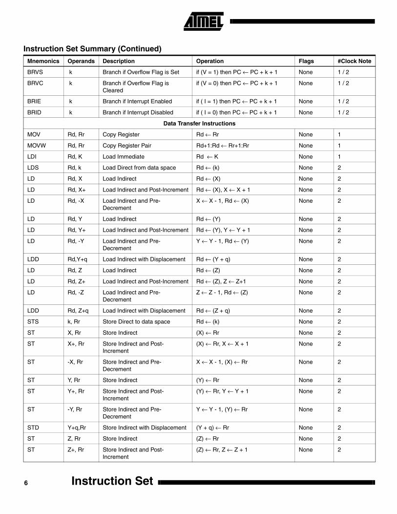
BRVS k Branch if Overflow Flag is Set if (V = 1) then PC ← PC + k + 1 None 1 / 2
BRVC k Branch if Overflow Flag is Cleared
if (V = 0) then PC ← PC + k + 1 None 1 / 2
BRIE k Branch if Interrupt Enabled if ( I = 1) then PC ← PC + k + 1 None 1 / 2
BRID k Branch if Interrupt Disabled if ( I = 0) then PC ← PC + k + 1 None 1 / 2
Data Transfer Instructions
MOV Rd, Rr Copy Register Rd ← Rr None 1
MOVW Rd, Rr Copy Register Pair Rd+1:Rd ← Rr+1:Rr None 1
LDI Rd, K Load Immediate Rd ← K None 1
LDS Rd, k Load Direct from data space Rd ← (k) None 2
LD Rd, X Load Indirect Rd ← (X) None 2
LD Rd, X+ Load Indirect and Post-Increment Rd ← (X), X ← X + 1 None 2
LD Rd, -X Load Indirect and Pre-Decrement
X ← X - 1, Rd ← (X) None 2
LD Rd, Y Load Indirect Rd ← (Y) None 2
LD Rd, Y+ Load Indirect and Post-Increment Rd ← (Y), Y ← Y + 1 None 2
LD Rd, -Y Load Indirect and Pre-Decrement
Y ← Y - 1, Rd ← (Y) None 2
LDD Rd,Y+q Load Indirect with Displacement Rd ← (Y + q) None 2
LD Rd, Z Load Indirect Rd ← (Z) None 2
LD Rd, Z+ Load Indirect and Post-Increment Rd ← (Z), Z ← Z+1 None 2
LD Rd, -Z Load Indirect and Pre-Decrement
Z ← Z - 1, Rd ← (Z) None 2
LDD Rd, Z+q Load Indirect with Displacement Rd ← (Z + q) None 2
STS k, Rr Store Direct to data space Rd ← (k) None 2
ST X, Rr Store Indirect (X) ← Rr None 2
ST X+, Rr Store Indirect and Post-Increment
(X) ← Rr, X ← X + 1 None 2
ST -X, Rr Store Indirect and Pre-Decrement
X ← X - 1, (X) ← Rr None 2
ST Y, Rr Store Indirect (Y) ← Rr None 2
ST Y+, Rr Store Indirect and Post-Increment
(Y) ← Rr, Y ← Y + 1 None 2
ST -Y, Rr Store Indirect and Pre-Decrement
Y ← Y - 1, (Y) ← Rr None 2
STD Y+q,Rr Store Indirect with Displacement (Y + q) ← Rr None 2
ST Z, Rr Store Indirect (Z) ← Rr None 2
ST Z+, Rr Store Indirect and Post-Increment
(Z) ← Rr, Z ← Z + 1 None 2
Instruction Set Summary (Continued)
Mnemonics Operands Description Operation Flags #Clock Note
Instruction Set6

Instruction Set
ST -Z, Rr Store Indirect and Pre-Decrement
Z ← Z - 1, (Z) ← Rr None 2
STD Z+q,Rr Store Indirect with Displacement (Z + q) ← Rr None 2
LPM Load Program Memory R0 ← (Z) None 3
LPM Rd, Z Load Program Memory Rd ← (Z) None 3
LPM Rd, Z+ Load Program Memory and Post-Increment
Rd ← (Z), Z ← Z + 1 None 3
ELPM Extended Load Program Memory R0 ← (RAMPZ:Z) None 3
ELPM Rd, Z Extended Load Program Memory Rd ← (RAMPZ:Z) None 3
ELPM Rd, Z+ Extended Load Program Memory and Post-Increment
Rd ← (RAMPZ:Z), Z ← Z + 1 None 3
SPM Store Program Memory (Z) ← R1:R0 None -
ESPM Extended Store Program Memory
(RAMPZ:Z) ← R1:R0 None -
IN Rd, A In From I/O Location Rd ← I/O(A) None 1
OUT A, Rr Out To I/O Location I/O(A) ← Rr None 1
PUSH Rr Push Register on Stack STACK ← Rr None 2
POP Rd Pop Register from Stack Rd ← STACK None 2
Bit and Bit-test Instructions
LSL Rd Logical Shift Left Rd(n+1)←Rd(n),Rd(0)←0,C←Rd(7) Z,C,N,V,H 1
LSR Rd Logical Shift Right Rd(n)←Rd(n+1),Rd(7)←0,C←Rd(0) Z,C,N,V 1
ROL Rd Rotate Left Through Carry Rd(0)←C,Rd(n+1)←Rd(n),C←Rd(7) Z,C,N,V,H 1
ROR Rd Rotate Right Through Carry Rd(7)←C,Rd(n)←Rd(n+1),C←Rd(0) Z,C,N,V 1
ASR Rd Arithmetic Shift Right Rd(n) ← Rd(n+1), n=0..6 Z,C,N,V 1
SWAP Rd Swap Nibbles Rd(3..0) ↔ Rd(7..4) None 1
BSET s Flag Set SREG(s) ← 1 SREG(s) 1
BCLR s Flag Clear SREG(s) ← 0 SREG(s) 1
SBI A, b Set Bit in I/O Register I/O(A, b) ← 1 None 2
CBI A, b Clear Bit in I/O Register I/O(A, b) ← 0 None 2
BST Rr, b Bit Store from Register to T T ← Rr(b) T 1
BLD Rd, b Bit load from T to Register Rd(b) ← T None 1
SEC Set Carry C ← 1 C 1
CLC Clear Carry C ← 0 C 1
SEN Set Negative Flag N ← 1 N 1
CLN Clear Negative Flag N ← 0 N 1
SEZ Set Zero Flag Z ← 1 Z 1
CLZ Clear Zero Flag Z ← 0 Z 1
Instruction Set Summary (Continued)
Mnemonics Operands Description Operation Flags #Clock Note
7

SEI Global Interrupt Enable I ← 1 I 1
CLI Global Interrupt Disable I ← 0 I 1
SES Set Signed Test Flag S ← 1 S 1
CLS Clear Signed Test Flag S ← 0 S 1
SEV Set Two’s Complement Overflow V ← 1 V 1
CLV Clear Two’s Complement Overflow
V ← 0 V 1
SET Set T in SREG T ← 1 T 1
CLT Clear T in SREG T ← 0 T 1
SEH Set Half Carry Flag in SREG H ← 1 H 1
CLH Clear Half Carry Flag in SREG H ← 0 H 1
NOP No Operation None 1
SLEEP Sleep (see specific descr. for Sleep) None 1
WDR Watchdog Reset (see specific descr. for WDR) None 1
Instruction Set Summary (Continued)
Mnemonics Operands Description Operation Flags #Clock Note
Instruction Set8

Instruction Set
ADC - Add with Carry
Description:
Adds two registers and the contents of the C flag and places the result in the destination register Rd.
Operation:
(i) Rd ← Rd + Rr + C
Syntax: Operands: Program Counter:
(i) ADC Rd,Rr 0 ≤ d ≤ 31, 0 ≤ r ≤ 31 PC ← PC + 1
16-bit Opcode:
Status Register (SREG) Boolean Formulae:
H: Rd3•Rr3+Rr3•R3+R3•Rd3Set if there was a carry from bit 3; cleared otherwise
S: N ⊕ V, For signed tests.
V: Rd7•Rr7•R7+Rd7•Rr7•R7Set if two’s complement overflow resulted from the operation; cleared otherwise.
N: R7Set if MSB of the result is set; cleared otherwise.
Z: R7• R6 •R5• R4 •R3 •R2 •R1 •R0Set if the result is $00; cleared otherwise.
C: Rd7•Rr7+Rr7•R7+R7•Rd7Set if there was carry from the MSB of the result; cleared otherwise.
R (Result) equals Rd after the operation.
Example:; Add R1:R0 to R3:R2
add r2,r0 ; Add low byte
adc r3,r1 ; Add with carry high byte
Words: 1 (2 bytes)Cycles: 1
0001 11rd dddd rrrr
I T H S V N Z C
- - ⇔ ⇔ ⇔ ⇔ ⇔ ⇔
9

ADD - Add without Carry
Description:
Adds two registers without the C flag and places the result in the destination register Rd.
Operation:
(i) Rd ← Rd + Rr
Syntax: Operands: Program Counter:
(i) ADD Rd,Rr 0 ≤ d ≤ 31, 0 ≤ r ≤ 31 PC ← PC + 1
16-bit Opcode:
Status Register (SREG) and Boolean Formulae:
H: Rd3•Rr3+Rr3•R3+R3•Rd3Set if there was a carry from bit 3; cleared otherwise
S: N ⊕ V, For signed tests.
V: Rd7•Rr7•R7+Rd7•Rr7•R7Set if two’s complement overflow resulted from the operation; cleared otherwise.
N: R7Set if MSB of the result is set; cleared otherwise.
Z: R7• R6 •R5• R4 •R3 •R2 •R1 •R0Set if the result is $00; cleared otherwise.
C: Rd7 •Rr7 +Rr7 •R7+ R7 •Rd7Set if there was carry from the MSB of the result; cleared otherwise.
R (Result) equals Rd after the operation.
Example:add r1,r2 ; Add r2 to r1 (r1=r1+r2)
add r28,r28 ; Add r28 to itself (r28=r28+r28)
Words: 1 (2 bytes)
Cycles: 1
0000 11rd dddd rrrr
I T H S V N Z C
- - ⇔ ⇔ ⇔ ⇔ ⇔ ⇔
Instruction Set10

Instruction Set
ADIW - Add Immediate to Word
Description:
Adds an immediate value (0-63) to a register pair and places the result in the register pair. This instruction operates on theupper four register pairs, and is well suited for operations on the pointer registers.
Operation:
(i) Rd+1:Rd ← Rd+1:Rd + K
Syntax: Operands: Program Counter:
(i) ADIW Rd,K d ∈ {24,26,28,30}, 0 ≤ K ≤ 63 PC ← PC + 1
16-bit Opcode:
Status Register (SREG) and Boolean Formulae:
S: N ⊕ V, For signed tests.
V: Rdh7 • R15Set if two’s complement overflow resulted from the operation; cleared otherwise.
N: R15Set if MSB of the result is set; cleared otherwise.
Z: R15 •R14 •R13 •R12 •R11 •R10 •R9 •R8 •R7• R6• R5• R4• R3• R2 •R1• R0Set if the result is $0000; cleared otherwise.
C: R15 • Rdh7Set if there was carry from the MSB of the result; cleared otherwise.
R (Result) equals Rdh:Rdl after the operation (Rdh7-Rdh0 = R15-R8, Rdl7-Rdl0=R7-R0).
Example:adiw r24,1 ; Add 1 to r25:r24
adiw r30,63 ; Add 63 to the Z pointer(r31:r30)
Words: 1 (2 bytes)
Cycles: 2
1001 0110 KKdd KKKK
I T H S V N Z C
- - - ⇔ ⇔ ⇔ ⇔ ⇔
11
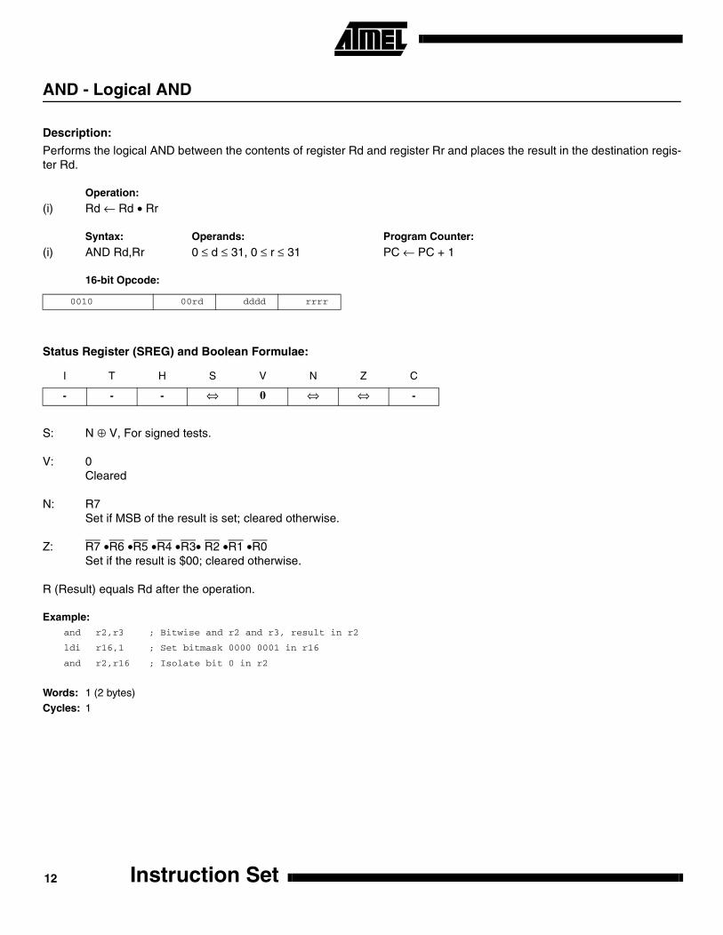
AND - Logical AND
Description:
Performs the logical AND between the contents of register Rd and register Rr and places the result in the destination regis-ter Rd.
Operation:
(i) Rd ← Rd • Rr
Syntax: Operands: Program Counter:
(i) AND Rd,Rr 0 ≤ d ≤ 31, 0 ≤ r ≤ 31 PC ← PC + 1
16-bit Opcode:
Status Register (SREG) and Boolean Formulae:
S: N ⊕ V, For signed tests.
V: 0Cleared
N: R7Set if MSB of the result is set; cleared otherwise.
Z: R7 •R6 •R5 •R4 •R3• R2 •R1 •R0Set if the result is $00; cleared otherwise.
R (Result) equals Rd after the operation.
Example:and r2,r3 ; Bitwise and r2 and r3, result in r2
ldi r16,1 ; Set bitmask 0000 0001 in r16
and r2,r16 ; Isolate bit 0 in r2
Words: 1 (2 bytes)Cycles: 1
0010 00rd dddd rrrr
I T H S V N Z C
- - - ⇔ 0 ⇔ ⇔ -
Instruction Set12
Instruction Set
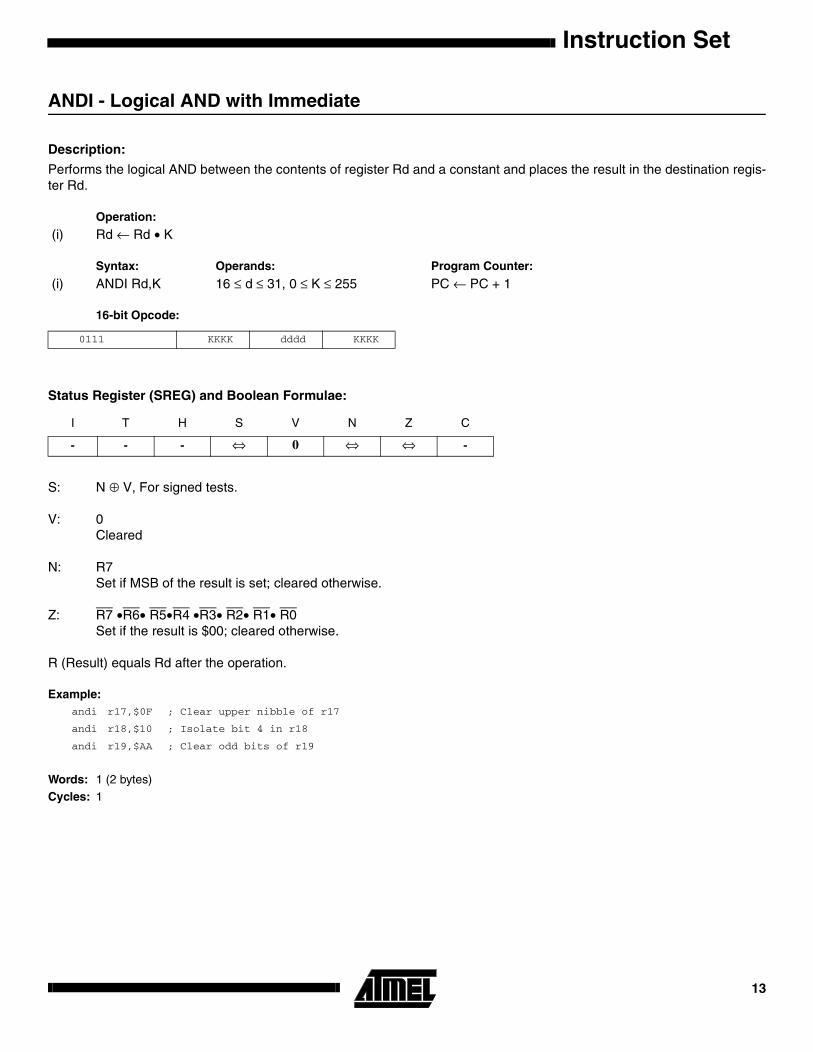
ANDI - Logical AND with Immediate
Description:
Performs the logical AND between the contents of register Rd and a constant and places the result in the destination regis-ter Rd.
Operation:
(i) Rd ← Rd • K
Syntax: Operands: Program Counter:
(i) ANDI Rd,K 16 ≤ d ≤ 31, 0 ≤ K ≤ 255 PC ← PC + 1
16-bit Opcode:
Status Register (SREG) and Boolean Formulae:
S: N ⊕ V, For signed tests.
V: 0Cleared
N: R7Set if MSB of the result is set; cleared otherwise.
Z: R7 •R6• R5•R4 •R3• R2• R1• R0Set if the result is $00; cleared otherwise.
R (Result) equals Rd after the operation.
Example:andi r17,$0F ; Clear upper nibble of r17
andi r18,$10 ; Isolate bit 4 in r18
andi r19,$AA ; Clear odd bits of r19
Words: 1 (2 bytes)Cycles: 1
0111 KKKK dddd KKKK
I T H S V N Z C
- - - ⇔ 0 ⇔ ⇔ -
13

ASR - Arithmetic Shift Right
Description:
Shifts all bits in Rd one place to the right. Bit 7 is held constant. Bit 0 is loaded into the C flag of the SREG. This operationeffectively divides a signed value by two without changing its sign. The carry flag can be used to round the result.
Operation:
(i)
Syntax: Operands: Program Counter:
(i) ASR Rd 0 ≤ d ≤ 31 PC ← PC + 1
16-bit Opcode:
Status Register (SREG) and Boolean Formulae:
S: N ⊕ V, For signed tests. V: N ⊕ C (For N and C after the shift)
N: R7Set if MSB of the result is set; cleared otherwise.
Z: R7 •R6 •R5• R4 •R3 •R2• R1• R0Set if the result is $00; cleared otherwise.
C: Rd0Set if, before the shift, the LSB of Rd was set; cleared otherwise.
R (Result) equals Rd after the operation.
Example:ldi r16,$10 ; Load decimal 16 into r16
asr r16 ; r16=r16 / 2
ldi r17,$FC ; Load -4 in r17
asr r17 ; r17=r17/2
Words: 1 (2 bytes)
Cycles: 1
1001 010d dddd 0101
I T H S V N Z C
- - - ⇔ ⇔ ⇔ ⇔ ⇔
b7-------------------b0 C
Instruction Set14
Instruction Set
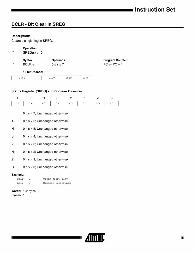
BCLR - Bit Clear in SREG
Description:
Clears a single flag in SREG.
Operation:
(i) SREG(s) ← 0
Syntax: Operands: Program Counter:
(i) BCLR s 0 ≤ s ≤ 7 PC ← PC + 1
16-bit Opcode:
Status Register (SREG) and Boolean Formulae:
I: 0 if s = 7; Unchanged otherwise.
T: 0 if s = 6; Unchanged otherwise.
H: 0 if s = 5; Unchanged otherwise.
S: 0 if s = 4; Unchanged otherwise.
V: 0 if s = 3; Unchanged otherwise.
N: 0 if s = 2; Unchanged otherwise.
Z: 0 if s = 1; Unchanged otherwise.
C: 0 if s = 0; Unchanged otherwise.
Example:bclr 0 ; Clear carry flag
bclr 7 ; Disable interrupts
Words: 1 (2 bytes)
Cycles: 1
1001 0100 1sss 1000
I T H S V N Z C
⇔ ⇔ ⇔ ⇔ ⇔ ⇔ ⇔ ⇔
15

BLD - Bit Load from the T Flag in SREG to a Bit in Register.
Description:
Copies the T flag in the SREG (status register) to bit b in register Rd.
Operation:
(i) Rd(b) ← T
Syntax: Operands: Program Counter:
(i) BLD Rd,b 0 ≤ d ≤ 31, 0 ≤ b ≤ 7 PC ← PC + 1
16 bit Opcode:
Status Register (SREG) and Boolean Formulae:
Example:; Copy bit
bst r1,2 ; Store bit 2 of r1 in T flag
bld r0,4 ; Load T flag into bit 4 of r0
Words: 1 (2 bytes)Cycles: 1
1111 100d dddd 0bbb
I T H S V N Z C
- - - - - - - -
Instruction Set16

Instruction Set
BRBC - Branch if Bit in SREG is Cleared
Description:
Conditional relative branch. Tests a single bit in SREG and branches relatively to PC if the bit is cleared. This instructionbranches relatively to PC in either direction (PC - 63 ≤ destination ≤ PC + 64). The parameter k is the offset from PC and is represented in two’s complement form.
Operation:
(i) If SREG(s) = 0 then PC ← PC + k + 1, else PC ← PC + 1
Syntax: Operands: Program Counter:
(i) BRBC s,k 0 ≤ s ≤ 7, -64 ≤ k ≤ +63 PC ← PC + k + 1PC ← PC + 1, if condition is false
16-bit Opcode:
Status Register (SREG) and Boolean Formulae:
Example:cpi r20,5 ; Compare r20 to the value 5
brbc 1,noteq ; Branch if zero flag cleared
...
noteq:nop ; Branch destination (do nothing)
Words: 1 (2 bytes)Cycles: 1 if condition is false
2 if condition is true
1111 01kk kkkk ksss
I T H S V N Z C
- - - - - - - -
17

BRBS - Branch if Bit in SREG is Set
Description:
Conditional relative branch. Tests a single bit in SREG and branches relatively to PC if the bit is set. This instructionbranches relatively to PC in either direction (PC - 63 ≤ destination ≤ PC + 64). The parameter k is the offset from PC and isrepresented in two’s complement form.
Operation:
(i) If SREG(s) = 1 then PC ← PC + k + 1, else PC ← PC + 1
Syntax: Operands: Program Counter:
(i) BRBS s,k 0 ≤ s ≤ 7, -64 ≤ k ≤ +63 PC ← PC + k + 1PC ← PC + 1, if condition is false
16-bit Opcode:
Status Register (SREG) and Boolean Formulae:
Example:bst r0,3 ; Load T bit with bit 3 of r0
brbs 6,bitset ; Branch T bit was set
...
bitset: nop ; Branch destination (do nothing)
Words: 1 (2 bytes)Cycles: 1 if condition is false
2 if condition is true
1111 00kk kkkk ksss
I T H S V N Z C
- - - - - - - -
Instruction Set18

Instruction Set
BRCC - Branch if Carry Cleared
Description:
Conditional relative branch. Tests the Carry flag (C) and branches relatively to PC if C is cleared. This instruction branchesrelatively to PC in either direction (PC - 63 ≤ destination ≤ PC + 64). The parameter k is the offset from PC and is repre-sented in two’s complement form. (Equivalent to instruction BRBC 0,k).
Operation:
(i) If C = 0 then PC ← PC + k + 1, else PC ← PC + 1
Syntax: Operands: Program Counter:
(i) BRCC k -64 ≤ k ≤ +63 PC ← PC + k + 1PC ← PC + 1, if condition is false
16-bit Opcode:
Status Register (SREG) and Boolean Formulae:
Example:add r22,r23 ; Add r23 to r22
brcc nocarry ; Branch if carry cleared
...
nocarry: nop ; Branch destination (do nothing)
Words: 1 (2 bytes)Cycles: 1 if condition is false
2 if condition is true
1111 01kk kkkk k000
I T H S V N Z C
- - - - - - - -
19
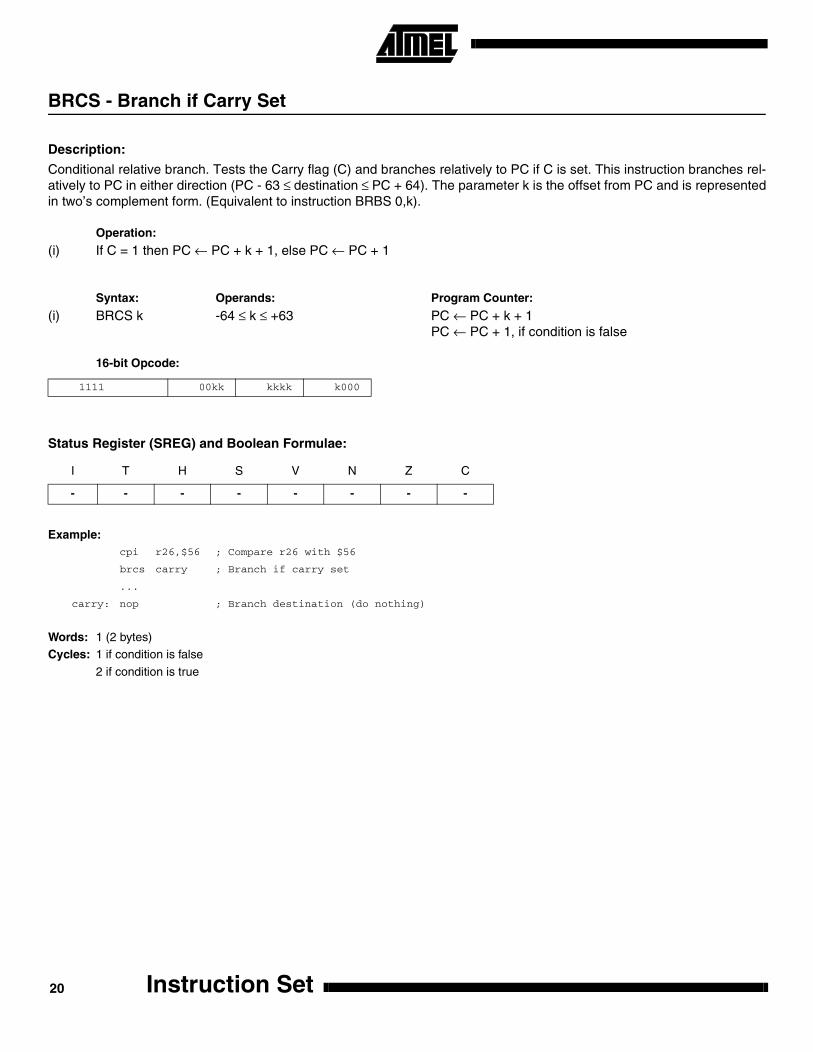
BRCS - Branch if Carry Set
Description:
Conditional relative branch. Tests the Carry flag (C) and branches relatively to PC if C is set. This instruction branches rel-atively to PC in either direction (PC - 63 ≤ destination ≤ PC + 64). The parameter k is the offset from PC and is representedin two’s complement form. (Equivalent to instruction BRBS 0,k).
Operation:
(i) If C = 1 then PC ← PC + k + 1, else PC ← PC + 1
Syntax: Operands: Program Counter:
(i) BRCS k -64 ≤ k ≤ +63 PC ← PC + k + 1PC ← PC + 1, if condition is false
16-bit Opcode:
Status Register (SREG) and Boolean Formulae:
Example:cpi r26,$56 ; Compare r26 with $56
brcs carry ; Branch if carry set
...
carry: nop ; Branch destination (do nothing)
Words: 1 (2 bytes)Cycles: 1 if condition is false
2 if condition is true
1111 00kk kkkk k000
I T H S V N Z C
- - - - - - - -
Instruction Set20
Instruction Set
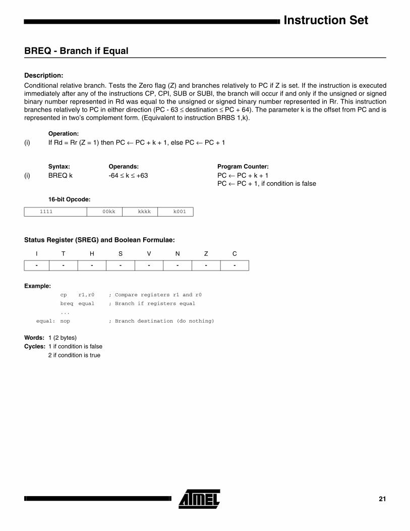
BREQ - Branch if Equal
Description:
Conditional relative branch. Tests the Zero flag (Z) and branches relatively to PC if Z is set. If the instruction is executedimmediately after any of the instructions CP, CPI, SUB or SUBI, the branch will occur if and only if the unsigned or signedbinary number represented in Rd was equal to the unsigned or signed binary number represented in Rr. This instructionbranches relatively to PC in either direction (PC - 63 ≤ destination ≤ PC + 64). The parameter k is the offset from PC and isrepresented in two’s complement form. (Equivalent to instruction BRBS 1,k).
Operation:
(i) If Rd = Rr (Z = 1) then PC ← PC + k + 1, else PC ← PC + 1
Syntax: Operands: Program Counter:
(i) BREQ k -64 ≤ k ≤ +63 PC ← PC + k + 1PC ← PC + 1, if condition is false
16-bit Opcode:
Status Register (SREG) and Boolean Formulae:
Example:cp r1,r0 ; Compare registers r1 and r0
breq equal ; Branch if registers equal
...
equal: nop ; Branch destination (do nothing)
Words: 1 (2 bytes)Cycles: 1 if condition is false
2 if condition is true
1111 00kk kkkk k001
I T H S V N Z C
- - - - - - - -
21

BRGE - Branch if Greater or Equal (Signed)
Description:
Conditional relative branch. Tests the Signed flag (S) and branches relatively to PC if S is cleared. If the instruction is exe-cuted immediately after any of the instructions CP, CPI, SUB or SUBI, the branch will occur if and only if the signed binarynumber represented in Rd was greater than or equal to the signed binary number represented in Rr. This instructionbranches relatively to PC in either direction (PC - 63 ≤ destination ≤ PC + 64). The parameter k is the offset from PC and isrepresented in two’s complement form. (Equivalent to instruction BRBC 4,k).
Operation:
(i) If Rd ≥ Rr (N ⊕ V = 0) then PC ← PC + k + 1, else PC ← PC + 1
Syntax: Operands: Program Counter:
(i) BRGE k -64 ≤ k ≤ +63 PC ← PC + k + 1PC ← PC + 1, if condition is false
16-bit Opcode:
Status Register (SREG) and Boolean Formulae:
Example:cp r11,r12 ; Compare registers r11 and r12
brge greateq ; Branch if r11 ≥ r12 (signed)
...
greateq: nop ; Branch destination (do nothing)
Words: 1 (2 bytes)Cycles: 1 if condition is false
2 if condition is true
1111 01kk kkkk k100
I T H S V N Z C
- - - - - - - -
Instruction Set22
Instruction Set
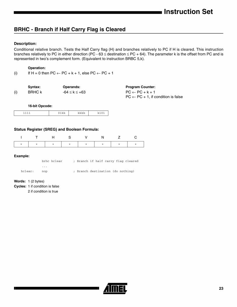
BRHC - Branch if Half Carry Flag is Cleared
Description:
Conditional relative branch. Tests the Half Carry flag (H) and branches relatively to PC if H is cleared. This instructionbranches relatively to PC in either direction (PC - 63 ≤ destination ≤ PC + 64). The parameter k is the offset from PC and isrepresented in two’s complement form. (Equivalent to instruction BRBC 5,k).
Operation:
(i) If H = 0 then PC ← PC + k + 1, else PC ← PC + 1
Syntax: Operands: Program Counter:
(i) BRHC k -64 ≤ k ≤ +63 PC ← PC + k + 1PC ← PC + 1, if condition is false
16-bit Opcode:
Status Register (SREG) and Boolean Formula:
Example:brhc hclear ; Branch if half carry flag cleared
...
hclear: nop ; Branch destination (do nothing)
Words: 1 (2 bytes)Cycles: 1 if condition is false
2 if condition is true
1111 01kk kkkk k101
I T H S V N Z C
- - - - - - - -
23
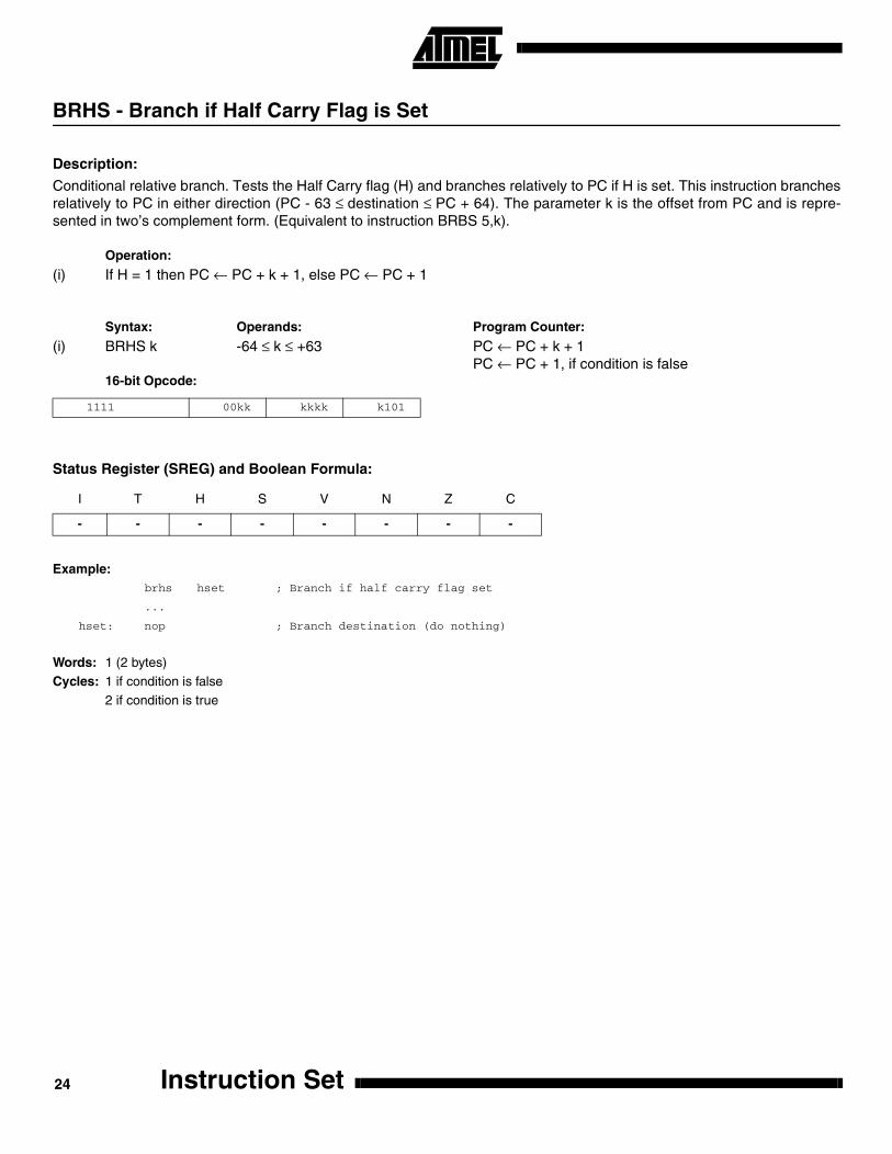
BRHS - Branch if Half Carry Flag is Set
Description:
Conditional relative branch. Tests the Half Carry flag (H) and branches relatively to PC if H is set. This instruction branchesrelatively to PC in either direction (PC - 63 ≤ destination ≤ PC + 64). The parameter k is the offset from PC and is repre-sented in two’s complement form. (Equivalent to instruction BRBS 5,k).
Operation:
(i) If H = 1 then PC ← PC + k + 1, else PC ← PC + 1
Syntax: Operands: Program Counter:
(i) BRHS k -64 ≤ k ≤ +63 PC ← PC + k + 1PC ← PC + 1, if condition is false
16-bit Opcode:
Status Register (SREG) and Boolean Formula:
Example:brhs hset ; Branch if half carry flag set
...
hset: nop ; Branch destination (do nothing)
Words: 1 (2 bytes)Cycles: 1 if condition is false
2 if condition is true
1111 00kk kkkk k101
I T H S V N Z C
- - - - - - - -
Instruction Set24

Instruction Set
BRID - Branch if Global Interrupt is Disabled
Description:
Conditional relative branch. Tests the Global Interrupt flag (I) and branches relatively to PC if I is cleared. This instructionbranches relatively to PC in either direction (PC - 63 ≤ destination ≤ PC + 64). The parameter k is the offset from PC and isrepresented in two’s complement form. (Equivalent to instruction BRBC 7,k).
Operation:
(i) If I = 0 then PC ← PC + k + 1, else PC ← PC + 1
Syntax: Operands: Program Counter:
(i) BRID k -64 ≤ k ≤ +63 PC ← PC + k + 1PC ← PC + 1, if condition is false
16-bit Opcode:
Status Register (SREG) and Boolean Formula:
Example:brid intdis ; Branch if interrupt disabled
...
intdis: nop ; Branch destination (do nothing)
Words: 1 (2 bytes)Cycles: 1 if condition is false
2 if condition is true
1111 01kk kkkk k111
I T H S V N Z C
- - - - - - - -
25

BRIE - Branch if Global Interrupt is Enabled
Description:
Conditional relative branch. Tests the Global Interrupt flag (I) and branches relatively to PC if I is set. This instructionbranches relatively to PC in either direction (PC - 63 ≤ destination ≤ PC + 64). The parameter k is the offset from PC and isrepresented in two’s complement form. (Equivalent to instruction BRBS 7,k).
Operation:
(i) If I = 1 then PC ← PC + k + 1, else PC ← PC + 1
Syntax: Operands: Program Counter:
(i) BRIE k -64 ≤ k ≤ +63 PC ← PC + k + 1PC ← PC + 1, if condition is false
16-bit Opcode:
Status Register (SREG) and Boolean Formula:
Example:brie inten ; Branch if interrupt enabled
...
inten: nop ; Branch destination (do nothing)
Words: 1 (2 bytes)Cycles: 1 if condition is false
2 if condition is true
1111 00kk kkkk k111
I T H S V N Z C
- - - - - - - -
Instruction Set26
Instruction Set
BRLO - Branch if Lower (Unsigned)
Description:
Conditional relative branch. Tests the Carry flag (C) and branches relatively to PC if C is set. If the instruction is executedimmediately after any of the instructions CP, CPI, SUB or SUBI, the branch will occur if and only if the unsigned binarynumber represented in Rd was smaller than the unsigned binary number represented in Rr. This instruction branches rela-tively to PC in either direction (PC - 63 ≤ destination ≤ PC + 64). The parameter k is the offset from PC and is representedin two’s complement form. (Equivalent to instruction BRBS 0,k).
Operation:
(i) If Rd < Rr (C = 1) then PC ← PC + k + 1, else PC ← PC + 1
Syntax: Operands: Program Counter:
(i) BRLO k -64 ≤ k ≤ +63 PC ← PC + k + 1PC ← PC + 1, if condition is false
16-bit Opcode:
Status Register (SREG) and Boolean Formulae:
Example:eor r19,r19 ; Clear r19
loop: inc r19 ; Increase r19
...
cpi r19,$10 ; Compare r19 with $10
brlo loop ; Branch if r19 < $10 (unsigned)
nop ; Exit from loop (do nothing)
Words: 1 (2 bytes)Cycles: 1 if condition is false
2 if condition is true
1111 00kk kkkk k000
I T H S V N Z C
- - - - - - - -
27
BRLT - Branch if Less Than (Signed)
Description:
Conditional relative branch. Tests the Signed flag (S) and branches relatively to PC if S is set. If the instruction is executedimmediately after any of the instructions CP, CPI, SUB or SUBI, the branch will occur if and only if the signed binary num-ber represented in Rd was less than the signed binary number represented in Rr. This instruction branches relatively to PCin either direction (PC - 63 ≤ destination ≤ PC + 64). The parameter k is the offset from PC and is represented in two’s com-plement form. (Equivalent to instruction BRBS 4,k).
Operation:
(i) If Rd < Rr (N ⊕ V = 1) then PC ← PC + k + 1, else PC ← PC + 1
Syntax: Operands: Program Counter:
(i) BRLT k -64 ≤ k ≤ +63 PC ← PC + k + 1PC ← PC + 1, if condition is false
16-bit Opcode:
Status Register (SREG) and Boolean Formulae:
Example:cp r16,r1 ; Compare r16 to r1
brlt less ; Branch if r16 < r1 (signed)
...
less: nop ; Branch destination (do nothing)
Words: 1 (2 bytes)Cycles: 1 if condition is false
2 if condition is true
1111 00kk kkkk k100
I T H S V N Z C
- - - - - - - -
Instruction Set28
Instruction Set
BRMI - Branch if Minus
Description:
Conditional relative branch. Tests the Negative flag (N) and branches relatively to PC if N is set. This instruction branchesrelatively to PC in either direction (PC - 63 ≤ destination ≤ PC + 64). The parameter k is the offset from PC and is repre-sented in two’s complement form. (Equivalent to instruction BRBS 2,k).
Operation:
(i) If N = 1 then PC ← PC + k + 1, else PC ← PC + 1
Syntax: Operands: Program Counter:
(i) BRMI k -64 ≤ k ≤ +63 PC ← PC + k + 1PC ← PC + 1, if condition is false
16-bit Opcode:
Status Register (SREG) and Boolean Formula:
Example:subi r18,4 ; Subtract 4 from r18
brmi negative ; Branch if result negative
...
negative: nop ; Branch destination (do nothing)
Words: 1 (2 bytes)Cycles: 1 if condition is false
2 if condition is true
1111 00kk kkkk k010
I T H S V N Z C
- - - - - - - -
29

BRNE - Branch if Not Equal
Description:
Conditional relative branch. Tests the Zero flag (Z) and branches relatively to PC if Z is cleared. If the instruction is exe-cuted immediately after any of the instructions CP, CPI, SUB or SUBI, the branch will occur if and only if the unsigned orsigned binary number represented in Rd was not equal to the unsigned or signed binary number represented in Rr. Thisinstruction branches relatively to PC in either direction (PC - 63 ≤ destination ≤ PC + 64). The parameter k is the offset fromPC and is represented in two’s complement form. (Equivalent to instruction BRBC 1,k).
Operation:
(i) If Rd ≠ Rr (Z = 0) then PC ← PC + k + 1, else PC ← PC + 1
Syntax: Operands: Program Counter:
(i) BRNE k -64 ≤ k ≤ +63 PC ← PC + k + 1PC ← PC + 1, if condition is false
16-bit Opcode:
Status Register (SREG) and Boolean Formula:
Example:eor r27,r27 ; Clear r27
loop: inc r27 ; Increase r27
...
cpi r27,5 ; Compare r27 to 5
brne loop ; Branch if r27<>5
nop ; Loop exit (do nothing)
Words: 1 (2 bytes)Cycles: 1 if condition is false
2 if condition is true
1111 01kk kkkk k001
I T H S V N Z C
- - - - - - - -
Instruction Set30

Instruction Set
BRPL - Branch if Plus
Description:
Conditional relative branch. Tests the Negative flag (N) and branches relatively to PC if N is cleared. This instructionbranches relatively to PC in either direction (PC - 63 ≤ destination ≤ PC + 64). The parameter k is the offset from PC and isrepresented in two’s complement form. (Equivalent to instruction BRBC 2,k).
Operation:
(i) If N = 0 then PC ← PC + k + 1, else PC ← PC + 1
Syntax: Operands: Program Counter:
(i) BRPL k -64 ≤ k ≤ +63 PC ← PC + k + 1PC ← PC + 1, if condition is false
16-bit Opcode:
Status Register (SREG) and Boolean Formula:
Example:subi r26,$50 ; Subtract $50 from r26
brpl positive ; Branch if r26 positive
...
positive: nop ; Branch destination (do nothing)
Words: 1 (2 bytes)Cycles: 1 if condition is false
2 if condition is true
1111 01kk kkkk k010
I T H S V N Z C
- - - - - - - -
31

BRSH - Branch if Same or Higher (Unsigned)
Description:
Conditional relative branch. Tests the Carry flag (C) and branches relatively to PC if C is cleared. If the instruction is exe-cuted immediately after execution of any of the instructions CP, CPI, SUB or SUBI the branch will occur if and only if theunsigned binary number represented in Rd was greater than or equal to the unsigned binary number represented in Rr.This instruction branches relatively to PC in either direction (PC - 63 ≤ destination ≤ PC + 64). The parameter k is the offsetfrom PC and is represented in two’s complement form. (Equivalent to instruction BRBC 0,k).
Operation:
(i) If Rd ≥Rr (C = 0) then PC ← PC + k + 1, else PC ← PC + 1
Syntax: Operands: Program Counter:
(i) BRSH k -64 ≤ k ≤ +63 PC ← PC + k + 1PC ← PC + 1, if condition is false
16-bit Opcode:
Status Register (SREG) and Boolean Formula:
Example:subi r19,4 ; Subtract 4 from r19
brsh highsm ; Branch if r19 >= 4 (unsigned)
...
highsm: nop ; Branch destination (do nothing)
Words: 1 (2 bytes)Cycles: 1 if condition is false
2 if condition is true
1111 01kk kkkk k000
I T H S V N Z C
- - - - - - - -
Instruction Set32
Instruction Set
BRTC - Branch if the T Flag is Cleared
Description:
Conditional relative branch. Tests the T flag and branches relatively to PC if T is cleared. This instruction branches rela-tively to PC in either direction (PC - 63 ≤ destination ≤ PC + 64). The parameter k is the offset from PC and is representedin two’s complement form. (Equivalent to instruction BRBC 6,k).
Operation:
(i) If T = 0 then PC ← PC + k + 1, else PC ← PC + 1
Syntax: Operands: Program Counter:
(i) BRTC k -64 ≤ k ≤ +63 PC ← PC + k + 1PC ← PC + 1, if condition is false
16-bit Opcode:
Status Register (SREG) and Boolean Formulae:
Example:bst r3,5 ; Store bit 5 of r3 in T flag
brtc tclear ; Branch if this bit was cleared
...
tclear: nop ; Branch destination (do nothing)
Words: 1 (2 bytes)Cycles: 1 if condition is false
2 if condition is true
1111 01kk kkkk k110
I T H S V N Z C
- - - - - - - -
33

BRTS - Branch if the T Flag is Set
Description:
Conditional relative branch. Tests the T flag and branches relatively to PC if T is set. This instruction branches relatively toPC in either direction (PC - 63 ≤ destination ≤ PC + 64). The parameter k is the offset from PC and is represented in two’scomplement form. (Equivalent to instruction BRBS 6,k).
Operation:
(i) If T = 1 then PC ← PC + k + 1, else PC ← PC + 1
Syntax: Operands: Program Counter:
(i) BRTS k -64 ≤ k ≤ +63 PC ← PC + k + 1PC ← PC + 1, if condition is false
16-bit Opcode:
Status Register (SREG) and Boolean Formulae:
Example:bst r3,5 ; Store bit 5 of r3 in T flag
brts tset ; Branch if this bit was set
...
tset: nop ; Branch destination (do nothing)
Words: 1 (2 bytes)Cycles: 1 if condition is false
2 if condition is true
1111 00kk kkkk k110
I T H S V N Z C
- - - - - - - -
Instruction Set34

Instruction Set
BRVC - Branch if Overflow Cleared
Description: Conditional relative branch. Tests the Overflow flag (V) and branches relatively to PC if V is cleared. This instruction branch-es relatively to PC in either direction (PC - 63 ≤ destination ≤ PC + 64). The parameter k is the offset from PC and is repre-sented in two’s complement form. (Equivalent to instruction BRBC 3,k).
Operation:
(i) If V = 0 then PC ← PC + k + 1, else PC ← PC + 1
Syntax: Operands: Program Counter:
(i) BRVC k -64 ≤ k ≤ +63 PC ← PC + k + 1PC ← PC + 1, if condition is false
16-bit Opcode:
Status Register (SREG) and Boolean Formula:
Example:add r3,r4 ; Add r4 to r3
brvc noover ; Branch if no overflow
...
noover: nop ; Branch destination (do nothing)
Words: 1 (2 bytes)Cycles: 1 if condition is false
2 if condition is true
1111 01kk kkkk k011
I T H S V N Z C
- - - - - - - -
35

BRVS - Branch if Overflow Set
Description:
Conditional relative branch. Tests the Overflow flag (V) and branches relatively to PC if V is set. This instruction branchesrelatively to PC in either direction (PC - 63 ≤ destination ≤ PC + 64). The parameter k is the offset from PC and is repre-sented in two’s complement form. (Equivalent to instruction BRBS 3,k).
Operation:
(i) If V = 1 then PC ← PC + k + 1, else PC ← PC + 1
Syntax: Operands: Program Counter:
(i) BRVS k -64 ≤ k ≤ +63 PC ← PC + k + 1PC ← PC + 1, if condition is false
16-bit Opcode:
Status Register (SREG) and Boolean Formula:
Example:add r3,r4 ; Add r4 to r3
brvs overfl ; Branch if overflow
...
overfl: nop ; Branch destination (do nothing)
Words: 1 (2 bytes)Cycles: 1 if condition is false
2 if condition is true
1111 00kk kkkk k011
I T H S V N Z C
- - - - - - - -
Instruction Set36
Instruction Set
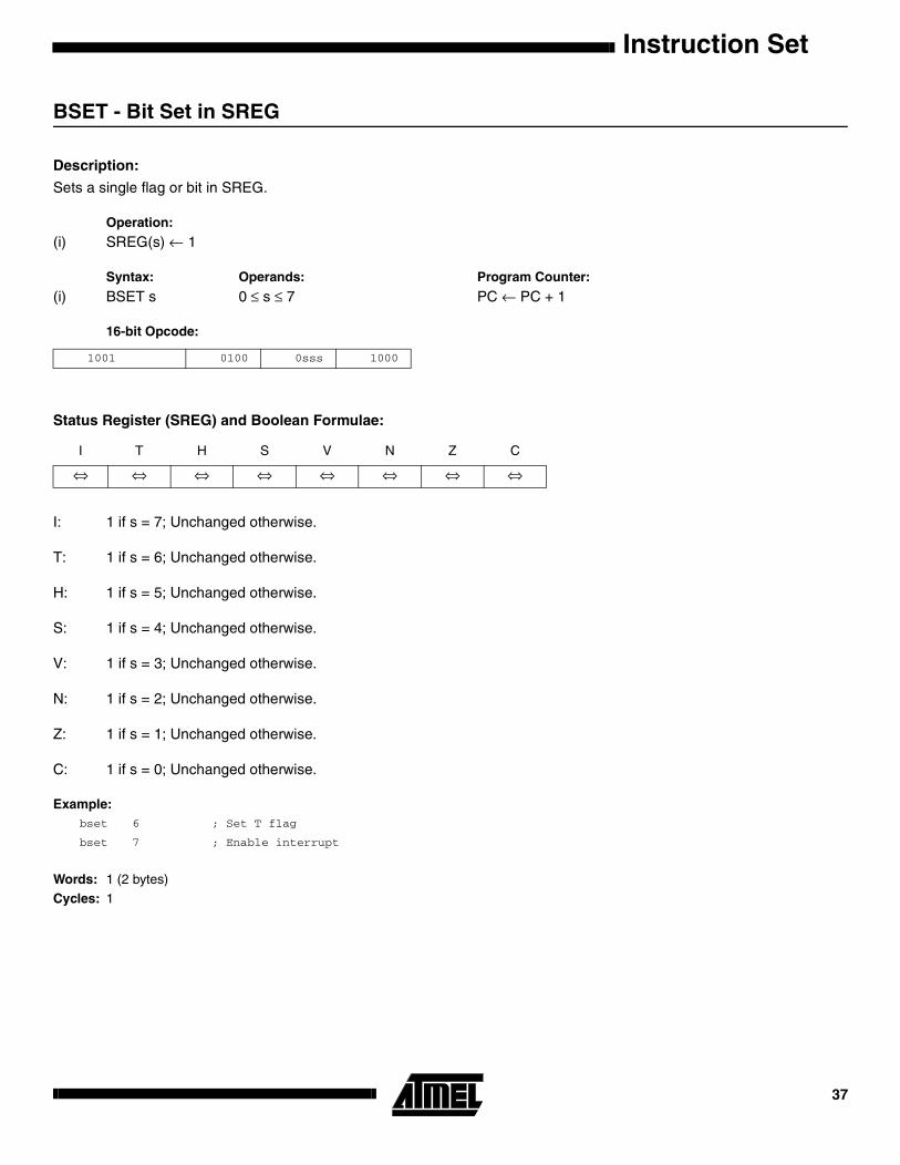
BSET - Bit Set in SREG
Description:
Sets a single flag or bit in SREG.
Operation:
(i) SREG(s) ← 1
Syntax: Operands: Program Counter:
(i) BSET s 0 ≤ s ≤ 7 PC ← PC + 1
16-bit Opcode:
Status Register (SREG) and Boolean Formulae:
I: 1 if s = 7; Unchanged otherwise.
T: 1 if s = 6; Unchanged otherwise.
H: 1 if s = 5; Unchanged otherwise.
S: 1 if s = 4; Unchanged otherwise.
V: 1 if s = 3; Unchanged otherwise.
N: 1 if s = 2; Unchanged otherwise.
Z: 1 if s = 1; Unchanged otherwise.
C: 1 if s = 0; Unchanged otherwise.
Example:bset 6 ; Set T flag
bset 7 ; Enable interrupt
Words: 1 (2 bytes)
Cycles: 1
1001 0100 0sss 1000
I T H S V N Z C
⇔ ⇔ ⇔ ⇔ ⇔ ⇔ ⇔ ⇔
37
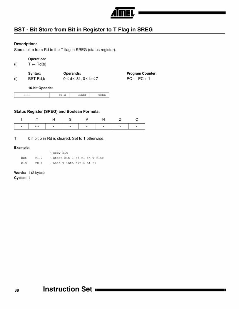
BST - Bit Store from Bit in Register to T Flag in SREG
Description:
Stores bit b from Rd to the T flag in SREG (status register).
Operation:
(i) T ← Rd(b)
Syntax: Operands: Program Counter:
(i) BST Rd,b 0 ≤ d ≤ 31, 0 ≤ b ≤ 7 PC ← PC + 1
16-bit Opcode:
Status Register (SREG) and Boolean Formula:
T: 0 if bit b in Rd is cleared. Set to 1 otherwise.
Example:; Copy bit
bst r1,2 ; Store bit 2 of r1 in T flag
bld r0,4 ; Load T into bit 4 of r0
Words: 1 (2 bytes)Cycles: 1
1111 101d dddd 0bbb
I T H S V N Z C
- ⇔ - - - - - -
Instruction Set38

Instruction Set
CALL - Long Call to a Subroutine
Description:
Calls to a subroutine within the entire program memory. The return address (to the instruction after the CALL) will be storedonto the stack. (See also RCALL). The stack pointer uses a post-decrement scheme during CALL.
Operation:
(i) PC ← k Devices with 16 bits PC, 128K bytes program memory maximum.(ii) PC ← k Devices with 22 bits PC, 8M bytes program memory maximum.
Syntax: Operands: Program Counter Stack:
(i) CALL k 0 ≤ k < 64K PC ← k STACK ← PC+2SP ← SP-2, (2 bytes, 16 bits)
(ii) CALL k 0 ≤ k < 4M PC ← k STACK ← PC+2SP ← SP-3 (3 bytes, 22 bits)
32-bit Opcode:
Status Register (SREG) and Boolean Formula:
Example:mov r16,r0 ; Copy r0 to r16
call check ; Call subroutine
nop ; Continue (do nothing)
...
check: cpi r16,$42 ; Check if r16 has a special value
breq error ; Branch if equal
ret ; Return from subroutine
...
error: rjmp error ; Infinite loop
Words: 2 (4 bytes)Cycles: 4, devices with 16 bit PC
5, devices with 22 bit PC
1001 010k kkkk 111k
kkkk kkkk kkkk kkkk
I T H S V N Z C
- - - - - - - -
39

CBI - Clear Bit in I/O Register
Description:
Clears a specified bit in an I/O register. This instruction operates on the lower 32 I/O registers - addresses 0-31.
Operation:
(i) I/O(A,b) ← 0
Syntax: Operands: Program Counter:
(i) CBI A,b 0 ≤ A ≤ 31, 0 ≤ b ≤ 7 PC ← PC + 1
16-bit Opcode:
Status Register (SREG) and Boolean Formula:
Example:cbi $12,7 ; Clear bit 7 in Port D
Words: 1 (2 bytes)Cycles: 2
1001 1000 AAAA Abbb
I T H S V N Z C
- - - - - - - -
Instruction Set40

Instruction Set
CBR - Clear Bits in Register
Description:
Clears the specified bits in register Rd. Performs the logical AND between the contents of register Rd and the complementof the constant mask K. The result will be placed in register Rd.
Operation:
(i) Rd ← Rd • ($FF - K)
Syntax: Operands: Program Counter:
(i) CBR Rd,K 16 ≤ d ≤ 31, 0 ≤ K ≤ 255 PC ← PC + 1
16-bit Opcode: (see ANDI with K complemented)
Status Register (SREG) and Boolean Formula:
S: N ⊕ V, For signed tests.
V: 0Cleared
N: R7Set if MSB of the result is set; cleared otherwise.
Z: R7 •R6 •R5• R4• R3 •R2• R1• R0Set if the result is $00; cleared otherwise.
R (Result) equals Rd after the operation.
Example:cbr r16,$F0 ; Clear upper nibble of r16
cbr r18,1 ; Clear bit 0 in r18
Words: 1 (2 bytes)Cycles: 1
I T H S V N Z C
- - - ⇔ 0 ⇔ ⇔ -
41
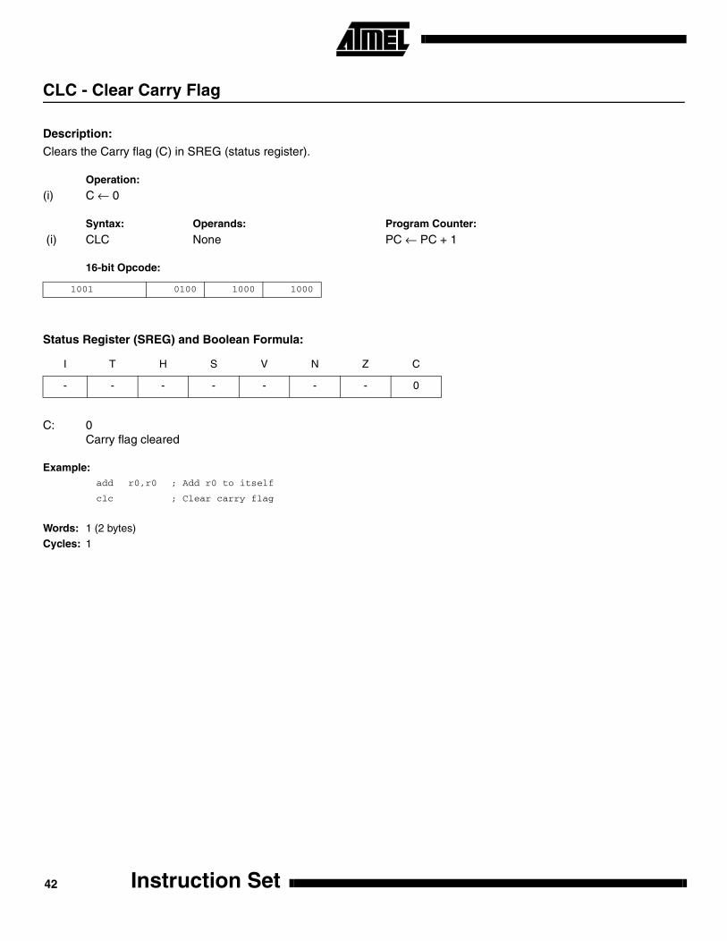
CLC - Clear Carry Flag
Description:
Clears the Carry flag (C) in SREG (status register).
Operation:
(i) C ← 0
Syntax: Operands: Program Counter:
(i) CLC None PC ← PC + 1
16-bit Opcode:
Status Register (SREG) and Boolean Formula:
C: 0Carry flag cleared
Example:add r0,r0 ; Add r0 to itself
clc ; Clear carry flag
Words: 1 (2 bytes)
Cycles: 1
1001 0100 1000 1000
I T H S V N Z C
- - - - - - - 0
Instruction Set42
Instruction Set
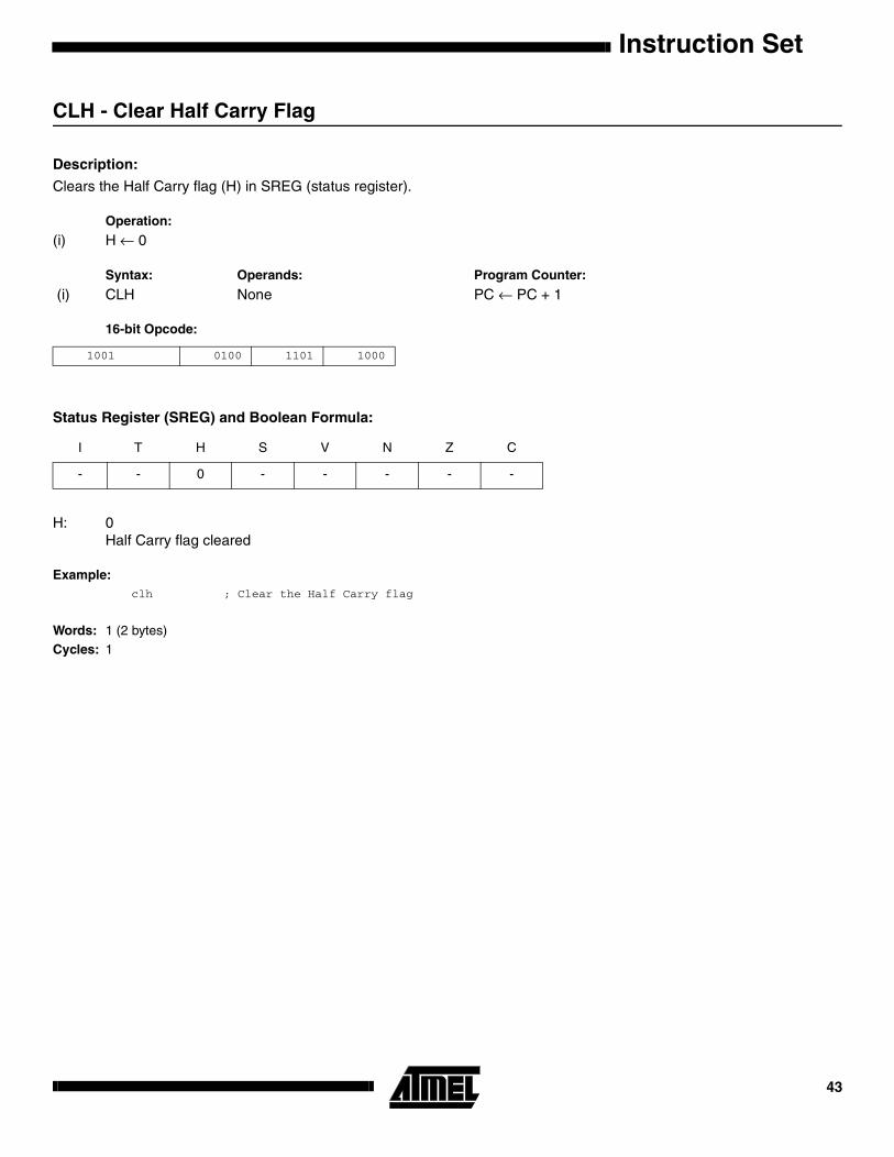
CLH - Clear Half Carry Flag
Description:
Clears the Half Carry flag (H) in SREG (status register).
Operation:
(i) H ← 0
Syntax: Operands: Program Counter:
(i) CLH None PC ← PC + 1
16-bit Opcode:
Status Register (SREG) and Boolean Formula:
H: 0Half Carry flag cleared
Example:clh ; Clear the Half Carry flag
Words: 1 (2 bytes)Cycles: 1
1001 0100 1101 1000
I T H S V N Z C
- - 0 - - - - -
43

CLI - Clear Global Interrupt Flag
Description:
Clears the Global Interrupt flag (I) in SREG (status register).
Operation:
(i) I ← 0
Syntax: Operands: Program Counter:
(i) CLI None PC ← PC + 1
16-bit Opcode:
Status Register (SREG) and Boolean Formula:
I: 0Global Interrupt flag cleared
Example:cli ; Disable interrupts
in r11,$16 ; Read port B
sei ; Enable interrupts
Words: 1 (2 bytes)Cycles: 1
1001 0100 1111 1000
I T H S V N Z C
0 - - - - - - -
Instruction Set44

Instruction Set
CLN - Clear Negative Flag
Description:
Clears the Negative flag (N) in SREG (status register).
Operation:
(i) N ← 0
Syntax: Operands: Program Counter:
(i) CLN None PC ← PC + 1
16-bit Opcode:
Status Register (SREG) and Boolean Formula:
N: 0Negative flag cleared
Example:add r2,r3 ; Add r3 to r2
cln ; Clear negative flag
Words: 1 (2 bytes)
Cycles: 1
1001 0100 1010 1000
I T H S V N Z C
- - - - - 0 - -
45
CLR - Clear Register
Description:
Clears a register. This instruction performs an Exclusive OR between a register and itself. This will clear all bits in theregister.
Operation:
(i) Rd ← Rd ⊕ Rd
Syntax: Operands: Program Counter:
(i) CLR Rd 0 ≤ d ≤ 31 PC ← PC + 1
16-bit Opcode: (see EOR Rd,Rd)
Status Register (SREG) and Boolean Formula:
S: 0Cleared
V: 0Cleared
N: 0Cleared
Z: 1Set
R (Result) equals Rd after the operation.
Example:clr r18 ; clear r18
loop: inc r18 ; increase r18
...
cpi r18,$50 ; Compare r18 to $50
brne loop
Words: 1 (2 bytes)Cycles: 1
0010 01dd dddd dddd
I T H S V N Z C
- - - 0 0 0 1 -
Instruction Set46

Instruction Set
CLS - Clear Signed Flag
Description:
Clears the Signed flag (S) in SREG (status register).
Operation:
(i) S ← 0
Syntax: Operands: Program Counter:
(i) CLS None PC ← PC + 1
16-bit Opcode:
Status Register (SREG) and Boolean Formula:
S: 0Signed flag cleared
Example:add r2,r3 ; Add r3 to r2
cls ; Clear signed flag
Words: 1 (2 bytes)
Cycles: 1
1001 0100 1100 1000
I T H S V N Z C
- - - 0 - - - -
47

CLT - Clear T Flag
Description:
Clears the T flag in SREG (status register).
Operation:
(i) T ← 0
Syntax: Operands: Program Counter:
(i) CLT None PC ← PC + 1
16-bit Opcode:
Status Register (SREG) and Boolean Formula:
T: 0T flag cleared
Example:clt ; Clear T flag
Words: 1 (2 bytes)Cycles: 1
1001 0100 1110 1000
I T H S V N Z C
- 0 - - - - - -
Instruction Set48

Instruction Set
CLV - Clear Overflow Flag
Description:
Clears the Overflow flag (V) in SREG (status register).
Operation:
(i) V ← 0
Syntax: Operands: Program Counter:
(i) CLV None PC ← PC + 1
16-bit Opcode:
Status Register (SREG) and Boolean Formula:
V: 0Overflow flag cleared
Example:add r2,r3 ; Add r3 to r2
clv ; Clear overflow flag
Words: 1 (2 bytes)
Cycles: 1
1001 0100 1011 1000
I T H S V N Z C
- - - - 0 - - -
49

CLZ - Clear Zero Flag
Description:
Clears the Zero flag (Z) in SREG (status register).
Operation:
(i) Z ← 0
Syntax: Operands: Program Counter:
(i) CLZ None PC ← PC + 1
16-bit Opcode:
Status Register (SREG) and Boolean Formula:
Z: 0Zero flag cleared
Example:add r2,r3 ; Add r3 to r2
clz ; Clear zero
Words: 1 (2 bytes)Cycles: 1
1001 0100 1001 1000
I T H S V N Z C
- - - - - - 0 -
Instruction Set50

Instruction Set
COM - One’s Complement
Description:
This instruction performs a one’s complement of register Rd.
Operation:
(i) Rd ← $FF - Rd
Syntax: Operands: Program Counter:
(i) COM Rd 0 ≤ d ≤ 31 PC ← PC + 1
16-bit Opcode:
Status Register (SREG) and Boolean Formulae:
S: N ⊕ VFor signed tests.
V: 0Cleared.
N: R7Set if MSB of the result is set; cleared otherwise.
Z: R7 •R6• R5• R4 •R3 •R2• R1 •R0Set if the result is $00; Cleared otherwise.
C: 1Set.
R (Result) equals Rd after the operation.
Example:com r4 ; Take one’s complement of r4
breq zero ; Branch if zero
...
zero: nop ; Branch destination (do nothing)
Words: 1 (2 bytes)Cycles: 1
1001 010d dddd 0000
I T H S V N Z C
- - - ⇔ 0 ⇔ ⇔ 1
51

CP - Compare
Description:
This instruction performs a compare between two registers Rd and Rr. None of the registers are changed. All conditionalbranches can be used after this instruction.
Operation:
(i) Rd - Rr
Syntax: Operands: Program Counter:
(i) CP Rd,Rr 0 ≤ d ≤ 31, 0 ≤ r ≤ 31 PC ← PC + 1
16-bit Opcode:
Status Register (SREG) and Boolean Formula:
H: Rd3 •Rr3+ Rr3 •R3 +R3• Rd3Set if there was a borrow from bit 3; cleared otherwise
S: N ⊕ V, For signed tests.
V: Rd7• Rd7 •R7+ Rd7 •Rr7 •R7Set if two’s complement overflow resulted from the operation; cleared otherwise.
N: R7Set if MSB of the result is set; cleared otherwise.
Z: R7• R6 •R5• R4 •R3 •R2 •R1 •R0Set if the result is $00; cleared otherwise.
C: Rd7 •Rr7+ Rr7• R7 +R7• Rd7Set if the absolute value of the contents of Rr is larger than the absolute value of Rd; cleared otherwise.
R (Result) after the operation.
Example:cp r4,r19 ; Compare r4 with r19
brne noteq ; Branch if r4 <> r19
...
noteq: nop ; Branch destination (do nothing)
Words: 1 (2 bytes)Cycles: 1
0001 01rd dddd rrrr
I T H S V N Z C
- - ⇔ ⇔ ⇔ ⇔ ⇔ ⇔
Instruction Set52

Instruction Set
CPC - Compare with Carry
Description:
This instruction performs a compare between two registers Rd and Rr and also takes into account the previous carry. Noneof the registers are changed. All conditional branches can be used after this instruction.
Operation:
(i) Rd - Rr - C
Syntax: Operands: Program Counter:
(i) CPC Rd,Rr 0 ≤ d ≤ 31, 0 ≤ r ≤ 31 PC ← PC + 1
16-bit Opcode:
Status Register (SREG) and Boolean Formula:
H: Rd3 •Rr3+ Rr3 •R3 +R3 •Rd3Set if there was a borrow from bit 3; cleared otherwise
S: N ⊕ V, For signed tests.
V: Rd7 •Rr7• R7+ Rd7• Rr7 •R7Set if two’s complement overflow resulted from the operation; cleared otherwise.
N: R7Set if MSB of the result is set; cleared otherwise.
Z: R7 •R6• R5• R4 •R3 •R2 •R1• R0 •ZPrevious value remains unchanged when the result is zero; cleared otherwise.
C: Rd7 •Rr7+ Rr7• R7 +R7 •Rd7Set if the absolute value of the contents of Rr plus previous carry is larger than the absolute value of Rd; clearedotherwise.
R (Result) after the operation.Example:
; Compare r3:r2 with r1:r0
cp r2,r0 ; Compare low byte
cpc r3,r1 ; Compare high byte
brne noteq ; Branch if not equal
...
noteq: nop ; Branch destination (do nothing)
Words: 1 (2 bytes)Cycles: 1
0000 01rd dddd rrrr
I T H S V N Z C
- - ⇔ ⇔ ⇔ ⇔ ⇔ ⇔
53
CPI - Compare with Immediate
Description:
This instruction performs a compare between register Rd and a constant. The register is not changed. All conditionalbranches can be used after this instruction.
Operation:
(i) Rd - K
Syntax: Operands: Program Counter:
(i) CPI Rd,K 16 ≤ d ≤ 31, 0≤ K ≤ 255 PC ← PC + 1
16-bit Opcode:
Status Register (SREG) and Boolean Formula:
H: Rd3 •K3+ K3• R3+ R3 •Rd3Set if there was a borrow from bit 3; cleared otherwise
S: N ⊕ V, For signed tests.
V: Rd7 •K7 •R7 +Rd7 •K7 •R7Set if two’s complement overflow resulted from the operation; cleared otherwise.
N: R7Set if MSB of the result is set; cleared otherwise.
Z: R7 •R6• R5 •R4• R3• R2 •R1 •R0Set if the result is $00; cleared otherwise.
C: Rd7 •K7 +K7 •R7+ R7 •Rd7Set if the absolute value of K is larger than the absolute value of Rd; cleared otherwise.
R (Result) after the operation.
Example:cpi r19,3 ; Compare r19 with 3
brne error ; Branch if r19<>3
...
error: nop ; Branch destination (do nothing)
Words: 1 (2 bytes)Cycles: 1
0011 KKKK dddd KKKK
I T H S V N Z C
- - ⇔ ⇔ ⇔ ⇔ ⇔ ⇔
Instruction Set54

Instruction Set
CPSE - Compare Skip if Equal
Description:
This instruction performs a compare between two registers Rd and Rr, and skips the next instruction if Rd = Rr.
Operation:
(i) If Rd = Rr then PC ← PC + 2 (or 3) else PC ← PC + 1
Syntax: Operands: Program Counter:
(i) CPSE Rd,Rr 0 ≤ d ≤ 31, 0 ≤ r ≤ 31 PC ← PC + 1, Condition false - no skipPC ← PC + 2, Skip a one word instructionPC ← PC + 3, Skip a two word instruction
16-bit Opcode:
Status Register (SREG) and Boolean Formula:
Example:inc r4 ; Increase r4
cpse r4,r0 ; Compare r4 to r0
neg r4 ; Only executed if r4<>r0
nop ; Continue (do nothing)
Words: 1 (2 bytes)Cycles: 1 if condition is false (no skip)
2 if condition is true (skip is executed) and the instruction skipped is 1 word3 if condition is true (skip is executed) and the instruction skipped is 2 words
0001 00rd dddd rrrr
I T H S V N Z C
- - - - - - - -
55

DEC - Decrement
Description:
Subtracts one -1- from the contents of register Rd and places the result in the destination register Rd.
The C flag in SREG is not affected by the operation, thus allowing the DEC instruction to be used on a loop counter in mul-tiple-precision computations.
When operating on unsigned values, only BREQ and BRNE branches can be expected to perform consistently. Whenoperating on two’s complement values, all signed branches are available.
Operation:
(i) Rd ← Rd - 1
Syntax: Operands: Program Counter:
(i) DEC Rd 0 ≤ d ≤ 31 PC ← PC + 1
16-bit Opcode:
Status Register and Boolean Formula:
S: N ⊕ VFor signed tests.
V: R7 •R6 •R5 •R4• R3• R2 •R1• R0Set if two’s complement overflow resulted from the operation; cleared otherwise. Two’s complement overflow occursif and only if Rd was $80 before the operation.
N: R7Set if MSB of the result is set; cleared otherwise.
Z: R7 •R6• R5 •R4• R3• R2• R1• R0Set if the result is $00; Cleared otherwise.
R (Result) equals Rd after the operation.
Example:ldi r17,$10 ; Load constant in r17
loop: add r1,r2 ; Add r2 to r1
dec r17 ; Decrement r17
brne loop ; Branch if r17<>0
nop ; Continue (do nothing)
Words: 1 (2 bytes)
Cycles: 1
1001 010d dddd 1010
I T H S V N Z C
- - - ⇔ ⇔ ⇔ ⇔ -
Instruction Set56
Instruction Set
EICALL - Extended Indirect Call to Subroutine
Description:
Indirect call of a subroutine pointed to by the Z (16 bits) pointer register in the register file and the EIND register in the I/Ospace. This instruction allows for indirect calls to the entire program memory space. This instruction is not implemented fordevices with 2 bytes PC, see ICALL. The stack pointer uses a post-decrement scheme during EICALL.
Operation:
(i) PC(15:0) ← Z(15:0)PC(21:16) ← EIND
Syntax: Operands: Program Counter: Stack:
(i) EICALL None See Operation STACK ← PC + 1SP ← SP - 3 (3 bytes, 22 bits)
16-bit Opcode:
Status Register (SREG) and Boolean Formula:
Example:ldi r16,$05 ; Set up EIND and Z pointer
out EIND,r16
ldi r30,$00
ldi r31,$10
eicall ; Call to $051000
Words: 1 (2 bytes)Cycles: 4 (only implemented in devices with 22 bit PC)
1001 0101 0001 1001
I T H S V N Z C
- - - - - - - -
57

EIJMP - Extended Indirect Jump
Description:
Indirect jump to the address pointed to by the Z (16 bits) pointer register in the register file and the EIND register in the I/Ospace. This instruction allows for indirect jumps to the entire program memory space.
Operation:
(i) PC(15:0) ← Z(15:0)PC(21:16) ← EIND
Syntax: Operands: Program Counter: Stack:
(i) EIJMP None See Operation Not Affected
16-bit Opcode:
Status Register (SREG) and Boolean Formula:
Example:ldi r16,$05 ; Set up EIND and Z pointer
out EIND,r16
ldi r30,$00
ldi r31,$10
eijmp ; Jump to $051000
Words: 1 (2 bytes)
Cycles: 2
1001 0100 0001 1001
I T H S V N Z C
- - - - - - - -
Instruction Set58

Instruction Set
ELPM - Extended Load Program Memory
Description:
Loads one byte pointed to by the Z register and the RAMPZ register in the I/O space, and places this byte in the destinationregister Rd. This instruction features a 100% space effective constant initialization or constant data fetch. The programmemory is organized in 16 bit words and the least significant bit of the Z pointer selects either low byte (0) or high byte (1).This instruction can address the entire program memory space. The Z pointer register can either be left unchanged by theoperation, or it can be incremented. The incrementation applies to the entire 24-bit concatenation of the RAMPZ and Zpointer registers.
The result of these combinations is undefined:
ELPM r30, Z+ELPM r31, Z+
Operation: Comment:
(i) R0 ← (RAMPZ:Z) RAMPZ:Z: Unchanged, R0 implied destination register(ii) Rd ← (RAMPZ:Z) RAMPZ:Z: Unchanged(iii) Rd ← (RAMPZ:Z) (RAMPZ:Z) ← (RAMPZ:Z) + 1 RAMPZ:Z: Post incremented
Syntax: Operands: Program Counter:
(i) ELPM None, R0 implied PC ← PC + 1(ii) ELPM Rd, Z 0 ≤ d ≤ 31 PC ← PC + 1(iii) ELPM Rd, Z+ 0 ≤ d ≤ 31 PC ← PC + 1
16 bit Opcode:
Status Register (SREG) and Boolean Formula:
Example:clr r16 ; Clear RAMPZ
out RAMPZ, r16
clr r31 ; Clear Z high byte
ldi r30,$F0 ; Set Z low byte
elpm r16, Z+ ; Load constant from program
; memory pointed to by RAMPZ:Z (r31:r30)
Words: 1 (2 bytes)
Cycles: 3
(i) 1001 0101 1101 1000
(ii) 1001 000d dddd 0110
(iii) 1001 000d dddd 0111
I T H S V N Z C
- - - - - - - -
59

EOR - Exclusive OR
Description:
Performs the logical EOR between the contents of register Rd and register Rr and places the result in the destination regis-ter Rd.
Operation:
(i) Rd ← Rd ⊕ Rr
Syntax: Operands: Program Counter:
(i) EOR Rd,Rr 0 ≤ d ≤ 31, 0 ≤ r ≤ 31 PC ← PC + 1
16-bit Opcode:
Status Register (SREG) and Boolean Formula:
S: N ⊕ V, For signed tests.
V: 0Cleared
N: R7Set if MSB of the result is set; cleared otherwise.
Z: R7 •R6 •R5 •R4• R3• R2 •R1• R0Set if the result is $00; cleared otherwise.
R (Result) equals Rd after the operation.
Example:eor r4,r4 ; Clear r4
eor r0,r22 ; Bitwise exclusive or between r0 and r22
Words: 1 (2 bytes)
Cycles: 1
0010 01rd dddd rrrr
I T H S V N Z C
- - - ⇔ 0 ⇔ ⇔ -
Instruction Set60
Instruction Set
ESPM - Extended Store Program Memory
Description:
ESPM can be used to erase a page in the program memory, to write a page in the program memory (that is alreadyerased), and to set boot loader lock bits. In some devices, the program memory can be written one word at a time, in otherdevices an entire page can be programmed simultaneously after first filling a temporary page buffer. In all cases, the pro-gram memory must be erased one page at a time. When erasing the program memory, the RAMPZ and Z registers areused as page address. When writing the program memory, the RAMPZ and Z registers are used as page or word address,and the R1:R0 register pair is used as data. When setting the boot loader lock bits, the R1:R0 register pair is used as data.Refer to the device documentation for detailed description of ESPM usage. This instruction can address the entire programmemory.
Operation: Comment:
(i) (RAMPZ:Z) ← $ffff Erase program memory page(ii) (RAMPZ:Z) ← R1:R0 Write program memory word(iii) (RAMPZ:Z) ← R1:R0 Write temporary page buffer(iv) (RAMPZ:Z) ← TEMP Write temporary page buffer to program memory(v) BLBITS ← R1:R0 Set boot loader lock bits
Syntax: Operands: Program Counter:
(i)-(v) ESPM None PC ← PC + 1
16-bit Opcode:
Status Register (SREG) and Boolean Formula:
1001 0101 1111 1000
I T H S V N Z C
- - - - - - - -
61

Example:; This example shows ESPM write of one word for devices with page write
clr r31 ; Clear Z high byte
clr r30 ; Clear Z low byte
ldi r16,$F0 ; Load RAMPZ register
out RAMPZ, r16 ;
ldi r16, $CF ; Load data to store
mov r1, r16
ldi r16, $FF
mov r0, r16
ldi r16,$03 ; Enable ESPM, erase page
out SPMCR, r16 ;
espm ; Erase page starting at $F00000
ldi r16,$01 ; Enable ESPM, store R1:R0 to temporary buffer
out SPMCR, r16 ;
espm ; Execute ESPM, store R1:R0 to temporary buffer location $F00000
ldi r16,$05 ; Enable ESPM, write page
out SPMCR, r16 ;
espm ; Execute SPM, store temporary buffer to program memory page starting at $F00000
Words: 1 (2 bytes)Cycles: depends on the operation
Instruction Set62

Instruction Set
FMUL - Fractional Multiply Unsigned
Description: This instruction performs 8-bit × 8-bit → 16-bit unsigned multiplication and shifts the result one bit left.
Let (N.Q) denote a fractional number with N binary digits left of the radix point, and Q binary digits right of the radix point. Amultiplication between two numbers in the formats (N1.Q1) and (N2.Q2) results in the format ((N1+N2).(Q1+Q2)). For sig-nal processing applications, the format (1.7) is widely used for the inputs, resulting in a (2.14) format for the product. A leftshift is required for the high byte of the product to be in the same format as the inputs. The FMUL instruction incorporatesthe shift operation in the same number of cycles as MUL.
The multiplicand Rd and the multiplier Rr are two registers containing unsigned fractional numbers where the implicit radixpoint lies between bit 6 and bit 7. The 16-bit unsigned fractional product with the implicit radix point between bit 14 and bit15 is placed in R1 (high byte) and R0 (low byte).
Operation:
(i) R1:R0 ← Rd × Rr (unsigned (1.15) ← unsigned (1.7) × unsigned (1.7))
Syntax: Operands: Program Counter:
(i) FMUL Rd,Rr 16 ≤ d ≤ 23, 16≤ r ≤ 23 PC ← PC + 1
16-bit Opcode:
Status Register (SREG) and Boolean Formula:
C: R16Set if bit 15 of the result before left shift is set; cleared otherwise.
Z: R15 •R14 •R13 •R12 •R11 •R10 •R9 •R8 •R7• R6• R5• R4• R3• R2 •R1• R0Set if the result is $0000; cleared otherwise.
R (Result) equals R1,R0 after the operation.
Example:fmul r23,r22 ; Multiply unsigned r23 and r22 in (1.7) format, result in (1.15) format
movw r22,r0 ; Copy result back in r23:r22
Words: 1 (2 bytes)
Cycles: 2
Rd Rr R1 R0
Multiplicand × Multiplier → Product High Product Low
8 8 16
0000 0011 0ddd 1rrr
I T H S V N Z C
- - - - - - ⇔ ⇔
63

FMULS - Fractional Multiply Signed
Description: This instruction performs 8-bit × 8-bit → 16-bit signed multiplication and shifts the result one bit left.
Let (N.Q) denote a fractional number with N binary digits left of the radix point, and Q binary digits right of the radix point. Amultiplication between two numbers in the formats (N1.Q1) and (N2.Q2) results in the format ((N1+N2).(Q1+Q2)). For sig-nal processing applications, the format (1.7) is widely used for the inputs, resulting in a (2.14) format for the product. A leftshift is required for the high byte of the product to be in the same format as the inputs. The FMULS instruction incorporatesthe shift operation in the same number of cycles as MULS.
The multiplicand Rd and the multiplier Rr are two registers containing signed fractional numbers where the implicit radixpoint lies between bit 6 and bit 7. The 16-bit signed fractional product with the implicit radix point between bit 14 and bit 15is placed in R1 (high byte) and R0 (low byte).
Operation:
(i) R1:R0 ← Rd × Rr (signed (1.15) ← signed (1.7) × signed (1.7))
Syntax: Operands: Program Counter:
(i) FMUL Rd,Rr 16 ≤ d ≤ 23, 16≤ r ≤ 23 PC ← PC + 1
16-bit Opcode:
Status Register (SREG) and Boolean Formulae:
C: R16Set if bit 15 of the result before left shift is set; cleared otherwise.
Z: R15 •R14 •R13 •R12 •R11 •R10 •R9 •R8 •R7• R6• R5• R4• R3• R2 •R1• R0Set if the result is $0000; cleared otherwise.
R (Result) equals R1,R0 after the operation.
Example:fmuls r23,r22 ; Multiply signed r23 and r22 in (1.7) format, result in (1.15) format
movw r22,r0 ; Copy result back in r23:r22
Words: 1 (2 bytes)
Cycles: 2
Rd Rr R1 R0
Multiplicand × Multiplier → Product High Product Low
8 8 16
0000 0011 1ddd 0rrr
I T H S V N Z C
- - - - - - ⇔ ⇔
Instruction Set64

Instruction Set
FMULSU - Fractional Multiply Signed with Unsigned
Description: This instruction performs 8-bit × 8-bit → 16-bit signed multiplication and shifts the result one bit left.
Let (N.Q) denote a fractional number with N binary digits left of the radix point, and Q binary digits right of the radix point. Amultiplication between two numbers in the formats (N1.Q1) and (N2.Q2) results in the format ((N1+N2).(Q1+Q2)). For sig-nal processing applications, the format (1.7) is widely used for the inputs, resulting in a (2.14) format for the product. A leftshift is required for the high byte of the product to be in the same format as the inputs. The FMULSU instruction incorpo-rates the shift operation in the same number of cycles as MULSU.
The multiplicand Rd and the multiplier Rr are two registers containing fractional numbers where the implicit radix point liesbetween bit 6 and bit 7. The multiplicand Rd is a signed fractional number, and the multiplier Rr is an unsigned fractionalnumber. The 16-bit signed fractional product with the implicit radix point between bit 14 and bit 15 is placed in R1 (highbyte) and R0 (low byte).
Operation:
(i) R1:R0 ← Rd × Rr (signed (1.15) ← signed (1.7) × unsigned (1.7))
Syntax: Operands: Program Counter:
(i) FMULSU Rd,Rr 16 ≤ d ≤ 23, 16≤ r ≤ 23 PC ← PC + 1
16-bit Opcode:
Status Register (SREG) and Boolean Formulae:
C: R16Set if bit 15 of the result before left shift is set; cleared otherwise.
Z: R15 •R14 •R13 •R12 •R11 •R10 •R9 •R8 •R7• R6• R5• R4• R3• R2 •R1• R0Set if the result is $0000; cleared otherwise.
R (Result) equals R1,R0 after the operation.
Example:fmulSU r23,r22 ; Multiply signed r23 with unsigned r22 in (1.7) format, signed result in (1.15) format
movw r22,r0 ; Copy result back in r23:r22
Words: 1 (2 bytes)
Cycles: 2
Rd Rr R1 R0
Multiplicand × Multiplier → Product High Product Low
8 8 16
0000 0011 1ddd 1rrr
I T H S V N Z C
- - - - - - ⇔ ⇔
65

ICALL - Indirect Call to Subroutine
Description:
Indirect call of a subroutine pointed to by the Z (16 bits) pointer register in the register file. The Z pointer register is 16 bitswide and allows call to a subroutine within the lowest 64K words (128K bytes) section in the program memory space. Thestack pointer uses a post-decrement scheme during ICALL.
Operation:
(i) PC(15:0) ← Z(15:0) Devices with 16 bits PC, 128K bytes program memory maximum.(ii) PC(15:0) ← Z(15:0) Devices with 22 bits PC, 8M bytes program memory maximum.
PC(21:16) ← 0
Syntax: Operands: Program Counter: Stack:
(i) ICALL None See Operation STACK ← PC + 1 SP ← SP - 2 (2 bytes, 16 bits)
(ii) ICALL None See Operation STACK ← PC + 1SP ← SP - 3 (3 bytes, 22 bits)
16-bit Opcode:
Status Register (SREG) and Boolean Formula:
Example:mov r30,r0 ; Set offset to call table
icall ; Call routine pointed to by r31:r30
Words: 1 (2 bytes)Cycles: 3 devices with 16 bit PC
4 devices with 22 bit PC
1001 0101 0000 1001
I T H S V N Z C
- - - - - - - -
Instruction Set66

Instruction Set
IJMP - Indirect Jump
Description:
Indirect jump to the address pointed to by the Z (16 bits) pointer register in the register file. The Z pointer register is 16 bitswide and allows jump within the lowest 64K words (128K bytes) section of program memory.
Operation:
(i) PC ← Z(15:0) Devices with 16 bits PC, 128K bytes program memory maximum.(ii) PC(15:0) ← Z(15:0) Devices with 22 bits PC, 8M bytes program memory maximum.
PC(21:16) ← 0
Syntax: Operands: Program Counter: Stack:
(i),(ii) IJMP None See Operation Not Affected
16-bit Opcode:
Status Register (SREG) and Boolean Formula:
Example:mov r30,r0 ; Set offset to jump table
ijmp ; Jump to routine pointed to by r31:r30
Words: 1 (2 bytes)
Cycles: 2
1001 0100 0000 1001
I T H S V N Z C
- - - - - - - -
67

IN - Load an I/O Location to Register
Description:
Loads data from the I/O Space (Ports, Timers, Configuration registers etc.) into register Rd in the register file.
Operation:
(i) Rd ← I/O(A)
Syntax: Operands: Program Counter:
(i) IN Rd,A 0 ≤ d ≤ 31, 0 ≤ A ≤ 63 PC ← PC + 1
16-bit Opcode:
Status Register (SREG) and Boolean Formula:
Example:in r25,$16 ; Read Port B
cpi r25,4 ; Compare read value to constant
breq exit ; Branch if r25=4
...
exit: nop ; Branch destination (do nothing)
Words: 1 (2 bytes)
Cycles: 1
1011 0AAd dddd AAAA
I T H S V N Z C
- - - - - - - -
Instruction Set68
Instruction Set
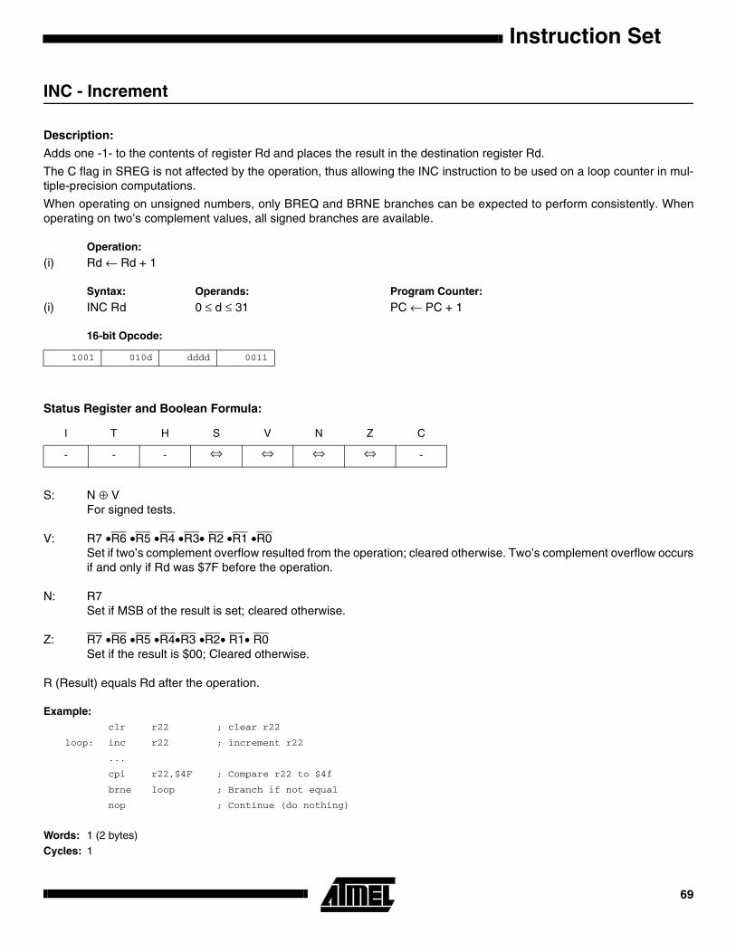
INC - Increment
Description:
Adds one -1- to the contents of register Rd and places the result in the destination register Rd.
The C flag in SREG is not affected by the operation, thus allowing the INC instruction to be used on a loop counter in mul-tiple-precision computations.
When operating on unsigned numbers, only BREQ and BRNE branches can be expected to perform consistently. Whenoperating on two’s complement values, all signed branches are available.
Operation:
(i) Rd ← Rd + 1
Syntax: Operands: Program Counter:
(i) INC Rd 0 ≤ d ≤ 31 PC ← PC + 1
16-bit Opcode:
Status Register and Boolean Formula:
S: N ⊕ VFor signed tests.
V: R7 •R6 •R5 •R4 •R3• R2 •R1 •R0Set if two’s complement overflow resulted from the operation; cleared otherwise. Two’s complement overflow occursif and only if Rd was $7F before the operation.
N: R7Set if MSB of the result is set; cleared otherwise.
Z: R7 •R6 •R5 •R4•R3 •R2• R1• R0Set if the result is $00; Cleared otherwise.
R (Result) equals Rd after the operation.
Example:clr r22 ; clear r22
loop: inc r22 ; increment r22
...
cpi r22,$4F ; Compare r22 to $4f
brne loop ; Branch if not equal
nop ; Continue (do nothing)
Words: 1 (2 bytes)Cycles: 1
1001 010d dddd 0011
I T H S V N Z C
- - - ⇔ ⇔ ⇔ ⇔ -
69

JMP - Jump
Description:
Jump to an address within the entire 4M (words) program memory. See also RJMP.
Operation:
(i) PC ← k
Syntax: Operands: Program Counter: Stack:
(i) JMP k 0 ≤ k < 4M PC ← k Unchanged
32-bit Opcode:
Status Register (SREG) and Boolean Formula:
Example:mov r1,r0 ; Copy r0 to r1
jmp farplc ; Unconditional jump
...
farplc: nop ; Jump destination (do nothing)
Words: 2 (4 bytes)
Cycles: 3
1001 010k kkkk 110k
kkkk kkkk kkkk kkkk
I T H S V N Z C
- - - - - - - -
Instruction Set70

Instruction Set
LD - Load Indirect from data space to Register using Index X
Description:
Loads one byte indirect from the data space to a register. For parts with SRAM, the data space consists of the register file,I/O memory and internal SRAM (and external SRAM if applicable). For parts without SRAM, the data space consists of theregister file only. The EEPROM has a separate address space.
The data location is pointed to by the X (16 bits) pointer register in the register file. Memory access is limited to the currentdata segment of 64K bytes. To access another data segment in devices with more than 64K bytes data space, the RAMPXin register in the I/O area has to be changed.
The X pointer register can either be left unchanged by the operation, or it can be post-incremented or pre-decremented.These features are especially suited for accessing arrays, tables, and stack pointer usage of the X pointer register. Notethat only the low byte of the X pointer is updated in devices with no more than 256 bytes data space. For such devices, thehigh byte of the pointer is not used by this instruction and can be used for other purposes. The RAMPX register in the I/Oarea is updated in parts with more than 64K bytes data space.
The result of these combinations is undefined:
LD r26, X+LD r27, X+LD r26, -XLD r27, -X
Using the X pointer:
Operation: Comment:
(i) Rd ← (X) X: Unchanged(ii) Rd ← (X) X ← X + 1 X: Post incremented(iii) X ← X - 1 Rd ← (X) X: Pre decremented
Syntax: Operands: Program Counter:
(i) LD Rd, X 0 ≤ d ≤ 31 PC ← PC + 1(ii) LD Rd, X+ 0 ≤ d ≤ 31 PC ← PC + 1(iii) LD Rd, -X 0 ≤ d ≤ 31 PC ← PC + 1
16-bit Opcode:
Status Register (SREG) and Boolean Formula:
(i) 1001 000d dddd 1100
(ii) 1001 000d dddd 1101
(iii) 1001 000d dddd 1110
I T H S V N Z C
- - - - - - - -
71

Example:clr r27 ; Clear X high byte
ldi r26,$60 ; Set X low byte to $60
ld r0,X+ ; Load r0 with data space loc. $60(X post inc)
ld r1,X ; Load r1 with data space loc. $61
ldi r26,$63 ; Set X low byte to $63
ld r2,X ; Load r2 with data space loc. $63
ld r3,-X ; Load r3 with data space loc. $62(X pre dec)
Words: 1 (2 bytes)Cycles: 2
Instruction Set72

Instruction Set
LD (LDD) - Load Indirect from data space to Register using Index Y
Description:
Loads one byte indirect with or without displacement from the data space to a register. For parts with SRAM, the dataspace consists of the register file, I/O memory and internal SRAM (and external SRAM if applicable). For parts withoutSRAM, the data space consists of the register file only. The EEPROM has a separate address space.
The data location is pointed to by the Y (16 bits) pointer register in the register file. Memory access is limited to the currentdata segment of 64K bytes. To access another data segment in devices with more than 64K bytes data space, the RAMPYin register in the I/O area has to be changed.
The Y pointer register can either be left unchanged by the operation, or it can be post-incremented or pre-decremented.These features are especially suited for accessing arrays, tables, and stack pointer usage of the Y pointer register. Notethat only the low byte of the Y pointer is updated in devices with no more than 256 bytes data space. For such devices, thehigh byte of the pointer is not used by this instruction and can be used for other purposes. The RAMPY register in the I/Oarea is updated in parts with more than 64K bytes data space, and the displacement is added to the entire 24-bit addresson such devices.
The result of these combinations is undefined:
LD r28, Y+LD r29, Y+LD r28, -YLD r29, -Y
Using the Y pointer:
Operation: Comment:
(i) Rd ← (Y) Y: Unchanged(ii) Rd ← (Y) Y ← Y + 1 Y: Post incremented(iii) Y ← Y - 1 Rd ← (Y) Y: Pre decremented(iiii) Rd ← (Y+q) Y: Unchanged, q: Displacement
Syntax: Operands: Program Counter:
(i) LD Rd, Y 0 ≤ d ≤ 31 PC ← PC + 1(ii) LD Rd, Y+ 0 ≤ d ≤ 31 PC ← PC + 1(iii) LD Rd, -Y 0 ≤ d ≤ 31 PC ← PC + 1(iiii) LDD Rd, Y+q 0 ≤ d ≤ 31, 0 ≤ q ≤ 63 PC ← PC + 1
16-bit Opcode:
Status Register (SREG) and Boolean Formula:
(i) 1000 000d dddd 1000
(ii) 1001 000d dddd 1001
(iii) 1001 000d dddd 1010
(iiii) 10q0 qq0d dddd 1qqq
I T H S V N Z C
- - - - - - - -
73

Example:clr r29 ; Clear Y high byte
ldi r28,$60 ; Set Y low byte to $60
ld r0,Y+ ; Load r0 with data space loc. $60(Y post inc)
ld r1,Y ; Load r1 with data space loc. $61
ldi r28,$63 ; Set Y low byte to $63
ld r2,Y ; Load r2 with data space loc. $63
ld r3,-Y ; Load r3 with data space loc. $62(Y pre dec)
ldd r4,Y+2 ; Load r4 with data space loc. $64
Words: 1 (2 bytes)Cycles: 2
Instruction Set74

Instruction Set
LD (LDD) - Load Indirect From data space to Register using Index Z
Description:
Loads one byte indirect with or without displacement from the data space to a register. For parts with SRAM, the dataspace consists of the register file, I/O memory and internal SRAM (and external SRAM if applicable). For parts withoutSRAM, the data space consists of the register file only. The EEPROM has a separate address space.
The data location is pointed to by the Z (16 bits) pointer register in the register file. Memory access is limited to the currentdata segment of 64K bytes. To access another data segment in devices with more than 64K bytes data space, the RAMPZin register in the I/O area has to be changed.
The Z pointer register can either be left unchanged by the operation, or it can be post-incremented or pre-decremented.These features are especially suited for stack pointer usage of the Z pointer register, however because the Z pointer regis-ter can be used for indirect subroutine calls, indirect jumps and table lookup, it is often more convenient to use the X or Ypointer as a dedicated stack pointer. Note that only the low byte of the Z pointer is updated in devices with no more than256 bytes data space. For such devices, the high byte of the pointer is not used by this instruction and can be used forother purposes. The RAMPZ register in the I/O area is updated in parts with more than 64K bytes data space, and that thedisplacement is added to the entire 24-bit address on such devices. For devices with more than 64K bytes program mem-ory and up to 64K bytes data memory, the RAMPZ register is only used by the ELPM and ESPM instructions. Hence,RAMPZ is not affected by the ST instruction.
For using the Z pointer for table lookup in program memory see the LPM and ELPM instructions.
The result of these combinations is undefined:
LD r30, Z+LD r31, Z+LD r30, -ZLD r31, -Z
Using the Z pointer:
Operation: Comment:
(i) Rd ← (Z) Z: Unchanged(ii) Rd ← (Z) Z ← Z + 1 Z: Post increment(iii) Z ← Z -1 Rd ← (Z) Z: Pre decrement(iiii) Rd ← (Z+q) Z: Unchanged, q: Displacement
Syntax: Operands: Program Counter:
(i) LD Rd, Z 0 ≤ d ≤ 31 PC ← PC + 1(ii) LD Rd, Z+ 0 ≤ d ≤ 31 PC ← PC + 1(iii) LD Rd, -Z 0 ≤ d ≤ 31 PC ← PC + 1(iiii) LDD Rd, Z+q 0 ≤ d ≤ 31, 0 ≤ q ≤ 63 PC ← PC + 1
75

16-bit Opcode:
Status Register (SREG) and Boolean Formula:
Example:clr r31 ; Clear Z high byte
ldi r30,$60 ; Set Z low byte to $60
ld r0,Z+ ; Load r0 with data space loc. $60(Z post inc)
ld r1,Z ; Load r1 with data space loc. $61
ldi r30,$63 ; Set Z low byte to $63
ld r2,Z ; Load r2 with data space loc. $63
ld r3,-Z ; Load r3 with data space loc. $62(Z pre dec)
ldd r4,Z+2 ; Load r4 with data space loc. $64
Words: 1 (2 bytes)Cycles: 2
(i) 1000 000d dddd 0000
(ii) 1001 000d dddd 0001
(iii) 1001 000d dddd 0010
(iiii) 10q0 qq0d dddd 0qqq
I T H S V N Z C
- - - - - - - -
Instruction Set76
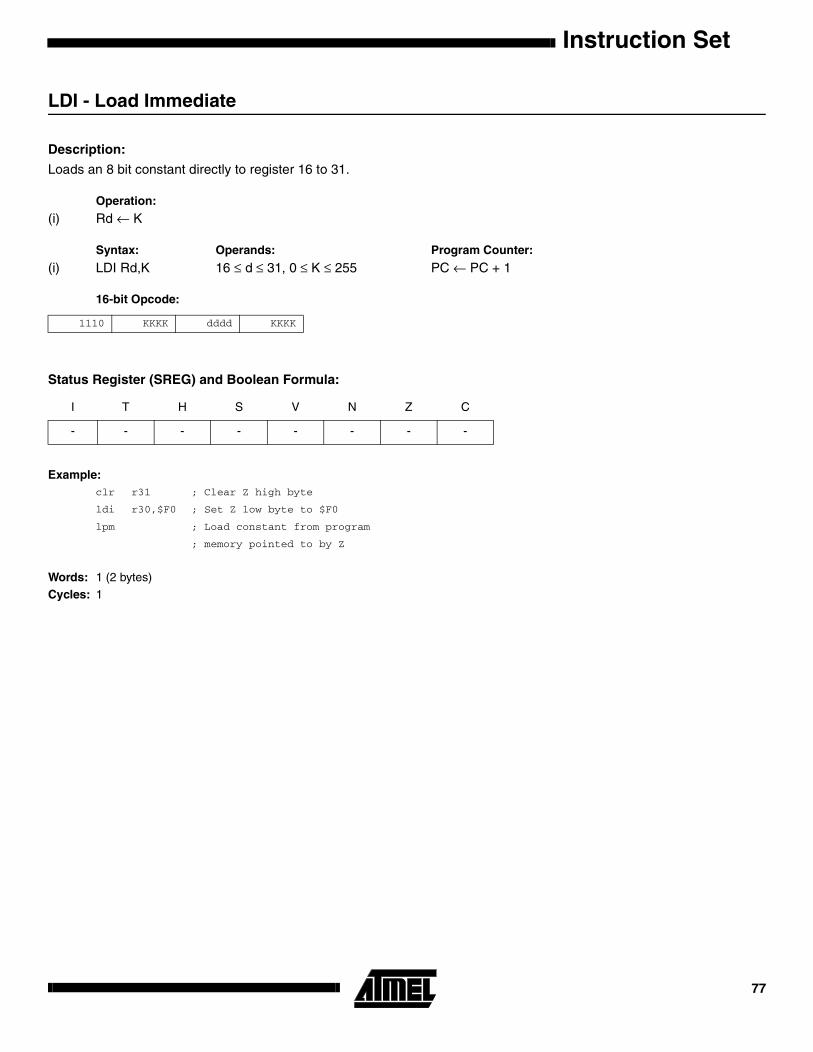
Instruction Set
LDI - Load Immediate
Description:
Loads an 8 bit constant directly to register 16 to 31.
Operation:
(i) Rd ← K
Syntax: Operands: Program Counter:
(i) LDI Rd,K 16 ≤ d ≤ 31, 0 ≤ K ≤ 255 PC ← PC + 1
16-bit Opcode:
Status Register (SREG) and Boolean Formula:
Example:clr r31 ; Clear Z high byte
ldi r30,$F0 ; Set Z low byte to $F0
lpm ; Load constant from program
; memory pointed to by Z
Words: 1 (2 bytes)Cycles: 1
1110 KKKK dddd KKKK
I T H S V N Z C
- - - - - - - -
77
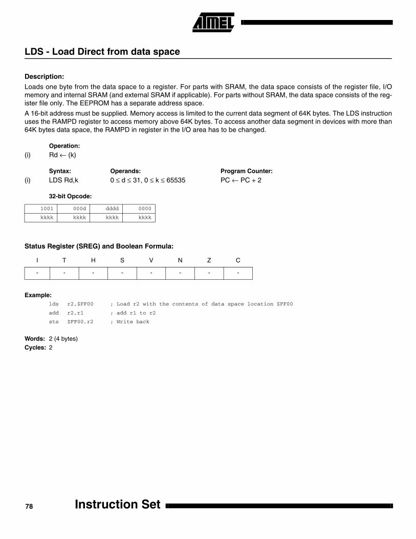
LDS - Load Direct from data space
Description:
Loads one byte from the data space to a register. For parts with SRAM, the data space consists of the register file, I/Omemory and internal SRAM (and external SRAM if applicable). For parts without SRAM, the data space consists of the reg-ister file only. The EEPROM has a separate address space.
A 16-bit address must be supplied. Memory access is limited to the current data segment of 64K bytes. The LDS instructionuses the RAMPD register to access memory above 64K bytes. To access another data segment in devices with more than64K bytes data space, the RAMPD in register in the I/O area has to be changed.
Operation:
(i) Rd ← (k)
Syntax: Operands: Program Counter:
(i) LDS Rd,k 0 ≤ d ≤ 31, 0 ≤ k ≤ 65535 PC ← PC + 2
32-bit Opcode:
Status Register (SREG) and Boolean Formula:
Example:lds r2,$FF00 ; Load r2 with the contents of data space location $FF00
add r2,r1 ; add r1 to r2
sts $FF00,r2 ; Write back
Words: 2 (4 bytes)Cycles: 2
1001 000d dddd 0000
kkkk kkkk kkkk kkkk
I T H S V N Z C
- - - - - - - -
Instruction Set78

Instruction Set
LPM - Load Program Memory
Description:
Loads one byte pointed to by the Z register into the destination register Rd. This instruction features a 100% space effec-tive constant initialization or constant data fetch. The program memory is organized in 16 bit words and the least significantbit of the Z pointer selects either low byte (0) or high byte (1). This instruction can address the first 64K bytes (32K words)of program memory. The Z pointer register can either be left unchanged by the operation, or it can be incremented. Theincrementation does not apply to the RAMPZ register.
The result of these combinations is undefined:
LPM r30, Z+LPM r31, Z+
Operation: Comment:
(i) R0 ← (Z) Z: Unchanged, R0 implied destination register(ii) Rd ← (Z) Z: Unchanged(iii) Rd ← (Z) Z ← Z + 1 Z: Post incremented
Syntax: Operands: Program Counter:
(i) LPM None, R0 implied PC ← PC + 1(ii) LPM Rd, Z 0 ≤ d ≤ 31 PC ← PC + 1(iii) LPM Rd, Z+ 0 ≤ d ≤ 31 PC ← PC + 1
16-bit Opcode:
Status Register (SREG) and Boolean Formula:
Example:clr r31 ; Clear Z high byte
ldi r30,$F0 ; Set Z low byte
lpm ; Load constant from program
; memory pointed to by Z (r31:r30)
Words: 1 (2 bytes)
Cycles: 3
(i) 1001 0101 1100 1000
(ii) 1001 000d dddd 0100
(iii) 1001 000d dddd 0101
I T H S V N Z C
- - - - - - - -
79
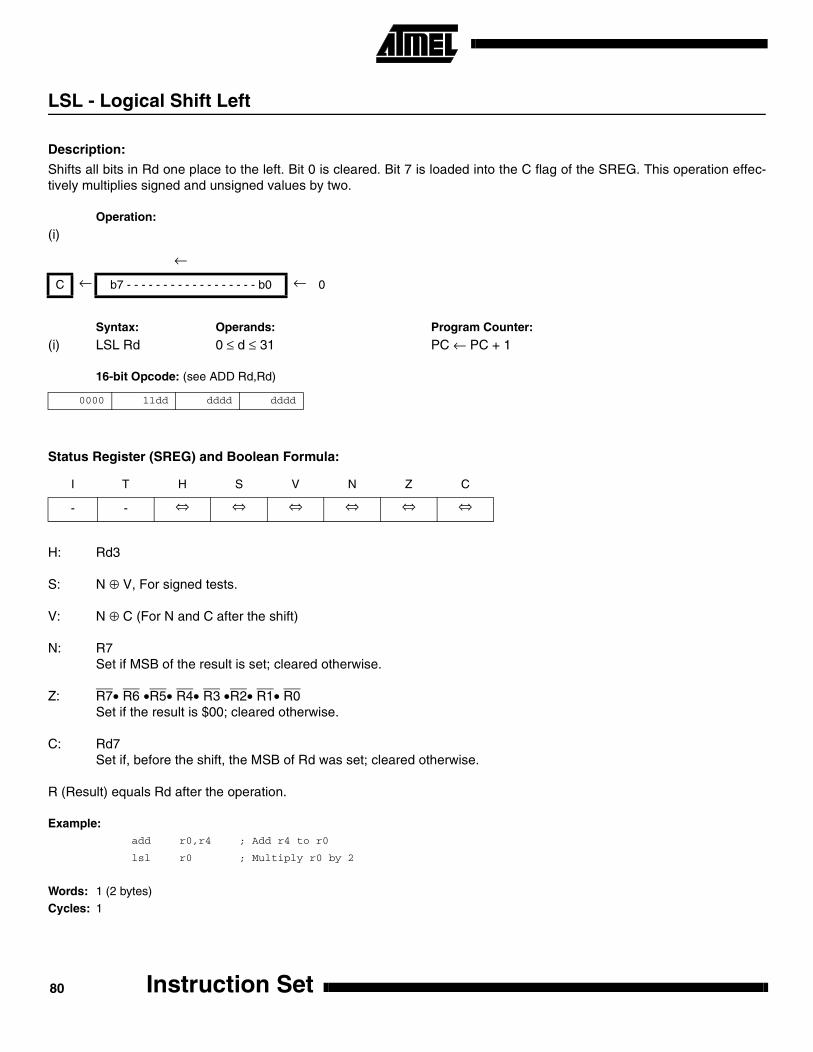
LSL - Logical Shift Left
Description:
Shifts all bits in Rd one place to the left. Bit 0 is cleared. Bit 7 is loaded into the C flag of the SREG. This operation effec-tively multiplies signed and unsigned values by two.
Operation:
(i)
Syntax: Operands: Program Counter:
(i) LSL Rd 0 ≤ d ≤ 31 PC ← PC + 1
16-bit Opcode: (see ADD Rd,Rd)
Status Register (SREG) and Boolean Formula:
H: Rd3
S: N ⊕ V, For signed tests. V: N ⊕ C (For N and C after the shift)
N: R7Set if MSB of the result is set; cleared otherwise.
Z: R7• R6 •R5• R4• R3 •R2• R1• R0Set if the result is $00; cleared otherwise.
C: Rd7Set if, before the shift, the MSB of Rd was set; cleared otherwise.
R (Result) equals Rd after the operation.
Example:add r0,r4 ; Add r4 to r0
lsl r0 ; Multiply r0 by 2
Words: 1 (2 bytes)Cycles: 1
←
C ← b7 - - - - - - - - - - - - - - - - - - b0 ← 0
0000 11dd dddd dddd
I T H S V N Z C
- - ⇔ ⇔ ⇔ ⇔ ⇔ ⇔
Instruction Set80

Instruction Set
LSR - Logical Shift Right
Description:
Shifts all bits in Rd one place to the right. Bit 7 is cleared. Bit 0 is loaded into the C flag of the SREG. This operation effec-tively divides an unsigned value by two. The C flag can be used to round the result.
Operation:
Syntax: Operands: Program Counter:
(i) LSR Rd 0 ≤ d ≤ 31 PC ← PC + 1
16-bit Opcode:
Status Register (SREG) and Boolean Formula:
S: N ⊕ V, For signed tests. V: N ⊕ C (For N and C after the shift)
N: 0
Z: R7• R6 •R5• R4• R3 •R2• R1• R0Set if the result is $00; cleared otherwise.
C: Rd0Set if, before the shift, the LSB of Rd was set; cleared otherwise.
R (Result) equals Rd after the operation.
Example:add r0,r4 ; Add r4 to r0
lsr r0 ; Divide r0 by 2
Words: 1 (2 bytes)Cycles: 1
→
0 → b7 - - - - - - - - - - - - - - - - - - b0 → C
1001 010d dddd 0110
I T H S V N Z C
- - - ⇔ ⇔ 0 ⇔ ⇔
81
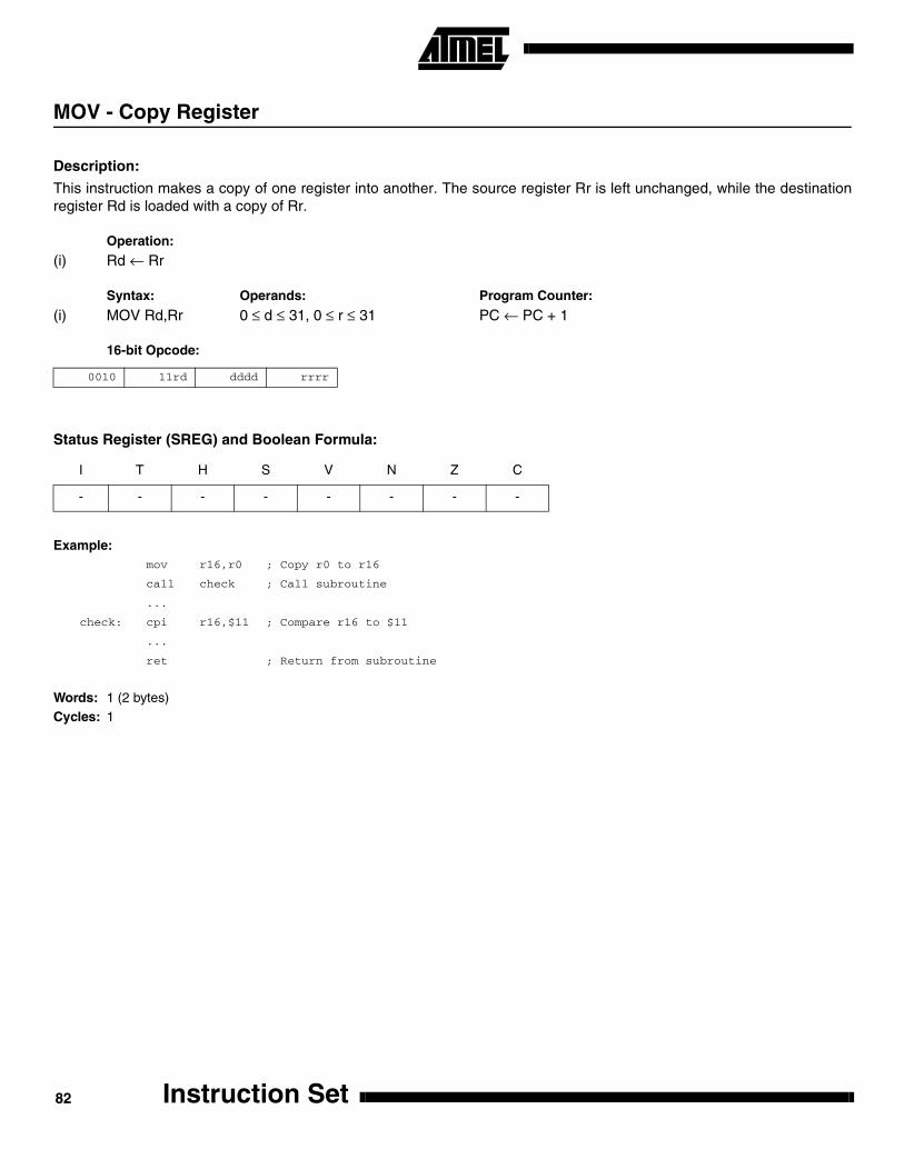
MOV - Copy Register
Description:
This instruction makes a copy of one register into another. The source register Rr is left unchanged, while the destinationregister Rd is loaded with a copy of Rr.
Operation:
(i) Rd ← Rr
Syntax: Operands: Program Counter:
(i) MOV Rd,Rr 0 ≤ d ≤ 31, 0 ≤ r ≤ 31 PC ← PC + 1
16-bit Opcode:
Status Register (SREG) and Boolean Formula:
Example:mov r16,r0 ; Copy r0 to r16
call check ; Call subroutine
...
check: cpi r16,$11 ; Compare r16 to $11
...
ret ; Return from subroutine
Words: 1 (2 bytes)Cycles: 1
0010 11rd dddd rrrr
I T H S V N Z C
- - - - - - - -
Instruction Set82

Instruction Set
MOVW - Copy Register Word
Description:
This instruction makes a copy of one register pair into another register pair. The source register pair Rr+1:Rr is leftunchanged, while the destination register pair Rd+1:Rd is loaded with a copy of Rr + 1:Rr.
Operation:
(i) Rd+1:Rd ← Rr+1:Rr
Syntax: Operands: Program Counter:
(i) MOVW Rd,Rr d ∈ {0,2,...,30}, r ∈ {0,2,...,30} PC ← PC + 1
16-bit Opcode:
Status Register (SREG) and Boolean Formula:
Example:movw r16,r0 ; Copy r1:r0 to r17:r16
call check ; Call subroutine
...
check: cpi r16,$11 ; Compare r16 to $11
...
cpi r17,$32 ; Compare r17 to $32
...
ret ; Return from subroutine
Words: 1 (2 bytes)
Cycles: 1
0000 0001 dddd rrrr
I T H S V N Z C
- - - - - - - -
83

MUL - Multiply Unsigned
Description:
This instruction performs 8-bit × 8-bit → 16-bit unsigned multiplication.
The multiplicand Rd and the multiplier Rr are two registers containing unsigned numbers. The 16-bit unsigned product isplaced in R1 (high byte) and R0 (low byte). Note that if the multiplicand or the multiplier is selected from R0 or R1 the resultwill overwrite those after multiplication.
Operation:
(i) R1:R0 ← Rd × Rr (unsigned ← unsigned × unsigned)
Syntax: Operands: Program Counter:
(i) MUL Rd,Rr 0 ≤ d ≤ 31, 0 ≤ r ≤ 31 PC ← PC + 1
16-bit Opcode:
Status Register (SREG) and Boolean Formulae:
C: R15Set if bit 15 of the result is set; cleared otherwise.
Z: R15 •R14 •R13 •R12 •R11 •R10 •R9 •R8 •R7• R6• R5• R4• R3• R2 •R1• R0Set if the result is $0000; cleared otherwise.
R (Result) equals R1,R0 after the operation.
Example:mul r5,r4 ; Multiply unsigned r5 and r4
movw r4,r0 ; Copy result back in r5:r4
Words: 1 (2 bytes)
Cycles: 2
Rd Rr R1 R0
Multiplicand × Multiplier → Product High Product Low
8 8 16
1001 11rd dddd rrrr
I T H S V N Z C
- - - - - - ⇔ ⇔
Instruction Set84

Instruction Set
MULS - Multiply Signed
Description: This instruction performs 8-bit × 8-bit → 16-bit signed multiplication.
The multiplicand Rd and the multiplier Rr are two registers containing signed numbers. The 16-bit signed product is placedin R1 (high byte) and R0 (low byte).
Operation:
(i) R1:R0 ← Rd × Rr (signed ← signed × signed)
Syntax: Operands: Program Counter:
(i) MULS Rd,Rr 16 ≤ d ≤ 31, 16 ≤ r ≤ 31 PC ← PC + 1
16-bit Opcode:
Status Register (SREG) and Boolean Formula:
C: R15Set if bit 15 of the result is set; cleared otherwise.
Z: R15 •R14 •R13 •R12 •R11 •R10 •R9 •R8 •R7• R6• R5• R4• R3• R2 •R1• R0Set if the result is $0000; cleared otherwise.
R (Result) equals R1,R0 after the operation.
Example:muls r21,r20 ; Multiply signed r21 and r20
movw r20,r0 ; Copy result back in r21:r20
Words: 1 (2 bytes)
Cycles: 2
Rd Rr R1 R0
Multiplicand × Multiplier → Product High Product Low
8 8 16
0000 0010 dddd rrrr
I T H S V N Z C
- - - - - - ⇔ ⇔
85

MULSU - Multiply Signed with Unsigned
Description: This instruction performs 8-bit × 8-bit → 16-bit multiplication of a signed and an unsigned number.
The multiplicand Rd and the multiplier Rr are two registers. The multiplicand Rd is a signed number, and the multiplier Rr isunsigned. The 16-bit signed product is placed in R1 (high byte) and R0 (low byte).
Operation:
(i) R1:R0 ← Rd × Rr (signed ← signed × unsigned)
Syntax: Operands: Program Counter:
(i) MULSU Rd,Rr 16 ≤ d ≤ 23, 16 ≤ r ≤ 23 PC ← PC + 1
16-bit Opcode:
Status Register (SREG) and Boolean Formula:
C: R15Set if bit 15 of the result is set; cleared otherwise.
Z: R15 •R14 •R13 •R12 •R11 •R10 •R9 •R8 •R7• R6• R5• R4• R3• R2 •R1• R0Set if the result is $0000; cleared otherwise.
R (Result) equals R1,R0 after the operation.
Example:mulsu r21,r20 ; Multiply signed r21 with unsigned r20, signed result
movw r20,r0 ; Copy result back in r21:r20
Words: 1 (2 bytes)
Cycles: 2
Rd Rr R1 R0
Multiplicand × Multiplier → Product High Product Low
8 8 16
0000 0011 0ddd 0rrr
I T H S V N Z C
- - - - - - ⇔ ⇔
Instruction Set86

Instruction Set
NEG - Two’s Complement
Description:
Replaces the contents of register Rd with its two’s complement; the value $80 is left unchanged.Operation:
(i) Rd ← $00 - Rd
Syntax: Operands: Program Counter:
(i) NEG Rd 0 ≤ d ≤ 31 PC ← PC + 1
16-bit Opcode:
Status Register (SREG) and Boolean Formula:
H: R3 + Rd3Set if there was a borrow from bit 3; cleared otherwise
S: N ⊕ VFor signed tests.
V: R7• R6 •R5• R4• R3 •R2• R1• R0Set if there is a two’s complement overflow from the implied subtraction from zero; cleared otherwise. A two’s com-plement overflow will occur if and only if the contents of the Register after operation (Result) is $80.
N: R7Set if MSB of the result is set; cleared otherwise.
Z: R7• R6 •R5• R4• R3 •R2• R1• R0Set if the result is $00; Cleared otherwise.
C: R7 + R6 + R5 + R4 + R3 + R2 + R1 + R0Set if there is a borrow in the implied subtraction from zero; cleared otherwise. The C flag will be set in all casesexcept when the contents of Register after operation is $00.
R (Result) equals Rd after the operation.
Example:sub r11,r0 ; Subtract r0 from r11
brpl positive ; Branch if result positive
neg r11 ; Take two’s complement of r11
positive: nop ; Branch destination (do nothing)
Words: 1 (2 bytes)Cycles: 1
1001 010d dddd 0001
I T H S V N Z C
- - ⇔ ⇔ ⇔ ⇔ ⇔ ⇔
87

NOP - No Operation
Description:
This instruction performs a single cycle No Operation.
Operation:
(i) No
Syntax: Operands: Program Counter:
(i) NOP None PC ← PC + 1
16-bit Opcode:
Status Register (SREG) and Boolean Formula:
Example:clr r16 ; Clear r16
ser r17 ; Set r17
out $18,r16 ; Write zeros to Port B
nop ; Wait (do nothing)
out $18,r17 ; Write ones to Port B
Words: 1 (2 bytes)
Cycles: 1
0000 0000 0000 0000
I T H S V N Z C
- - - - - - - -
Instruction Set88

Instruction Set
OR - Logical OR
Description:
Performs the logical OR between the contents of register Rd and register Rr and places the result in the destination registerRd.
Operation:
(i) Rd ← Rd v Rr
Syntax: Operands: Program Counter:
(i) OR Rd,Rr 0 ≤ d ≤ 31, 0 ≤ r ≤ 31 PC ← PC + 1
16-bit Opcode:
Status Register (SREG) and Boolean Formula:
S: N ⊕ V, For signed tests.
V: 0Cleared
N: R7Set if MSB of the result is set; cleared otherwise.
Z: R7• R6 •R5• R4• R3 •R2• R1• R0Set if the result is $00; cleared otherwise.
R (Result) equals Rd after the operation.
Example:or r15,r16 ; Do bitwise or between registers
bst r15,6 ; Store bit 6 of r15 in T flag
brts ok ; Branch if T flag set
...
ok: nop ; Branch destination (do nothing)
Words: 1 (2 bytes)
Cycles: 1
0010 10rd dddd rrrr
I T H S V N Z C
- - - ⇔ 0 ⇔ ⇔ -
89

ORI - Logical OR with Immediate
Description:
Performs the logical OR between the contents of register Rd and a constant and places the result in the destination registerRd.
Operation:
(i) Rd ← Rd v K
Syntax: Operands: Program Counter:
(i) ORI Rd,K 16 ≤ d ≤ 31, 0 ≤ K ≤ 255 PC ← PC + 1
16-bit Opcode:
Status Register (SREG) and Boolean Formula:
S: N ⊕ V, For signed tests.
V: 0Cleared
N: R7Set if MSB of the result is set; cleared otherwise.
Z: R7• R6 •R5• R4• R3 •R2• R1• R0Set if the result is $00; cleared otherwise.
R (Result) equals Rd after the operation.
Example:ori r16,$F0 ; Set high nibble of r16
ori r17,1 ; Set bit 0 of r17
Words: 1 (2 bytes)
Cycles: 1
0110 KKKK dddd KKKK
I T H S V N Z C
- - - ⇔ 0 ⇔ ⇔ -
Instruction Set90

Instruction Set
OUT - Store Register to I/O Location
Description:
Stores data from register Rr in the register file to I/O Space (Ports, Timers, Configuration registers etc.).
Operation:
(i) I/O(A) ← Rr
Syntax: Operands: Program Counter:
(i) OUT A,Rr 0 ≤ r ≤ 31, 0 ≤ A ≤ 63 PC ← PC + 1
16-bit Opcode:
Status Register (SREG) and Boolean Formula:
Example:clr r16 ; Clear r16
ser r17 ; Set r17
out $18,r16 ; Write zeros to Port B
nop ; Wait (do nothing)
out $18,r17 ; Write ones to Port B
Words: 1 (2 bytes)
Cycles: 1
1011 1AAr rrrr AAAA
I T H S V N Z C
- - - - - - - -
91

POP - Pop Register from Stack
Description:
This instruction loads register Rd with a byte from the STACK. The stack pointer is pre-incremented by 1 before the POP.
Operation:
(i) Rd ← STACK
Syntax: Operands: Program Counter: Stack:
(i) POP Rd 0 ≤ d ≤ 31 PC ← PC + 1 SP ← SP + 1
16-bit Opcode:
Status Register (SREG) and Boolean Formula:
Example:call routine ; Call subroutine
...
routine: push r14 ; Save r14 on the stack
push r13 ; Save r13 on the stack
...
pop r13 ; Restore r13
pop r14 ; Restore r14
ret ; Return from subroutine
Words: 1 (2 bytes)
Cycles: 2
1001 000d dddd 1111
I T H S V N Z C
- - - - - - - -
Instruction Set92
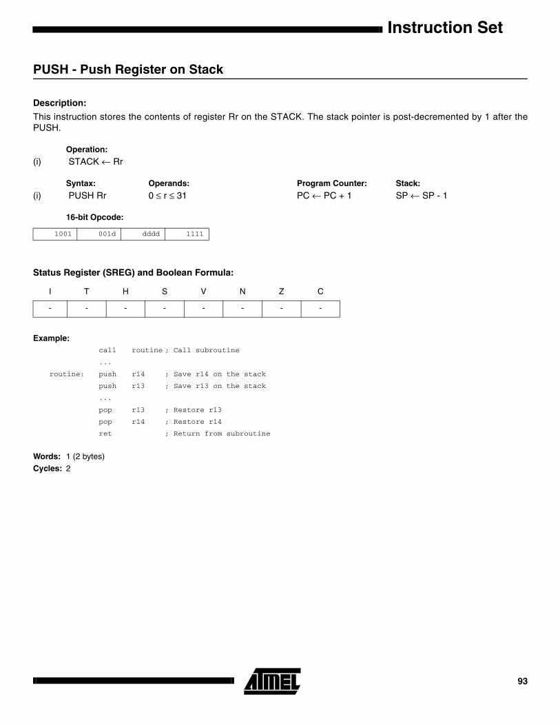
Instruction Set
PUSH - Push Register on Stack
Description:
This instruction stores the contents of register Rr on the STACK. The stack pointer is post-decremented by 1 after thePUSH.
Operation:
(i) STACK ← Rr
Syntax: Operands: Program Counter: Stack:
(i) PUSH Rr 0 ≤ r ≤ 31 PC ← PC + 1 SP ← SP - 1
16-bit Opcode:
Status Register (SREG) and Boolean Formula:
Example:call routine ; Call subroutine
...
routine: push r14 ; Save r14 on the stack
push r13 ; Save r13 on the stack
...
pop r13 ; Restore r13
pop r14 ; Restore r14
ret ; Return from subroutine
Words: 1 (2 bytes)
Cycles: 2
1001 001d dddd 1111
I T H S V N Z C
- - - - - - - -
93

RCALL - Relative Call to Subroutine
Description:
Relative call to an address within PC - 2K + 1 and PC + 2K (words). The return address (the instruction after the RCALL) isstored onto the stack. (See also CALL). In the assembler, labels are used instead of relative operands. For AVR microcon-trollers with program memory not exceeding 4K words (8K bytes) this instruction can address the entire memory from everyaddress location. The stack pointer uses a post-decrement scheme during RCALL.
Operation:
(i) PC ← PC + k + 1 Devices with 16 bits PC, 128K bytes program memory maximum.(ii) PC ← PC + k + 1 Devices with 22 bits PC, 8M bytes program memory maximum.
Syntax: Operands: Program Counter: Stack:
(i) RCALL k -2K ≤ k < 2K PC ← PC + k + 1 STACK ← PC + 1SP ← SP - 2 (2 bytes, 16 bits)
(ii) RCALL k -2K ≤ k < 2K PC ← PC + k + 1 STACK ← PC + 1 SP ← SP - 3 (3 bytes, 22 bits)
16-bit Opcode:
Status Register (SREG) and Boolean Formula:
Example:rcall routine ; Call subroutine
...
routine: push r14 ; Save r14 on the stack
...
pop r14 ; Restore r14
ret ; Return from subroutine
Words: 1 (2 bytes)Cycles: 3 devices with 16-bit PC
4 devices with 22-bit PC
1101 kkkk kkkk kkkk
I T H S V N Z C
- - - - - - - -
Instruction Set94

Instruction Set
RET - Return from Subroutine
Description:
Returns from subroutine. The return address is loaded from the STACK. The stack pointer uses a pre-increment schemeduring RET.
Operation:
(i) PC(15:0) ← STACK Devices with 16 bits PC, 128K bytes program memory maximum.(ii) PC(21:0) ← STACK Devices with 22 bits PC, 8M bytes program memory maximum.
Syntax: Operands: Program Counter: Stack:
(i) RET None See Operation SP←SP + 2, (2bytes,16 bits)
(ii) RET None See Operation SP←SP + 3, (3bytes,22 bits)
16-bit Opcode:
Status Register (SREG) and Boolean Formula:
Example:call routine ; Call subroutine
...
routine: push r14 ; Save r14 on the stack
...
pop r14 ; Restore r14
ret ; Return from subroutine
Words: 1 (2 bytes)Cycles: 4 devices with 16-bit PC
5 devices with 22-bit PC
1001 0101 0000 1000
I T H S V N Z C
- - - - - - - -
95
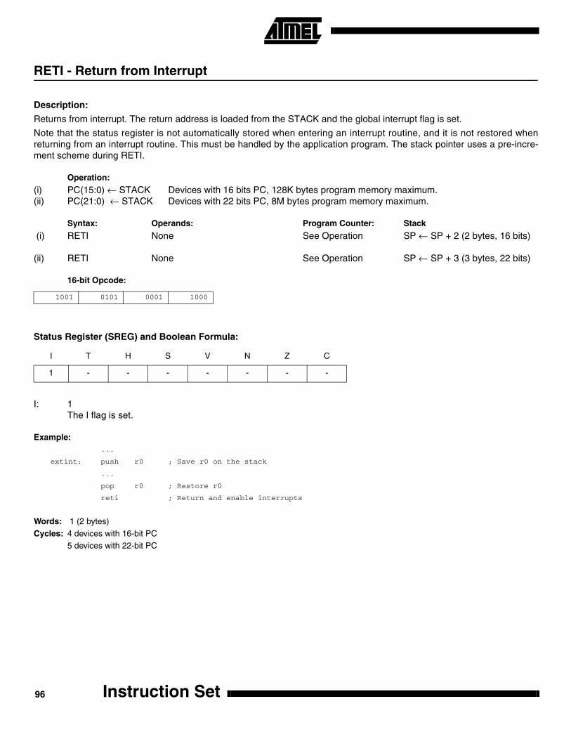
RETI - Return from Interrupt
Description:
Returns from interrupt. The return address is loaded from the STACK and the global interrupt flag is set.
Note that the status register is not automatically stored when entering an interrupt routine, and it is not restored whenreturning from an interrupt routine. This must be handled by the application program. The stack pointer uses a pre-incre-ment scheme during RETI.
Operation:
(i) PC(15:0) ← STACK Devices with 16 bits PC, 128K bytes program memory maximum.(ii) PC(21:0) ← STACK Devices with 22 bits PC, 8M bytes program memory maximum.
Syntax: Operands: Program Counter: Stack
(i) RETI None See Operation SP ← SP + 2 (2 bytes, 16 bits)
(ii) RETI None See Operation SP ← SP + 3 (3 bytes, 22 bits)
16-bit Opcode:
Status Register (SREG) and Boolean Formula:
I: 1The I flag is set.
Example:...
extint: push r0 ; Save r0 on the stack
...
pop r0 ; Restore r0
reti ; Return and enable interrupts
Words: 1 (2 bytes)
Cycles: 4 devices with 16-bit PC5 devices with 22-bit PC
1001 0101 0001 1000
I T H S V N Z C
1 - - - - - - -
Instruction Set96
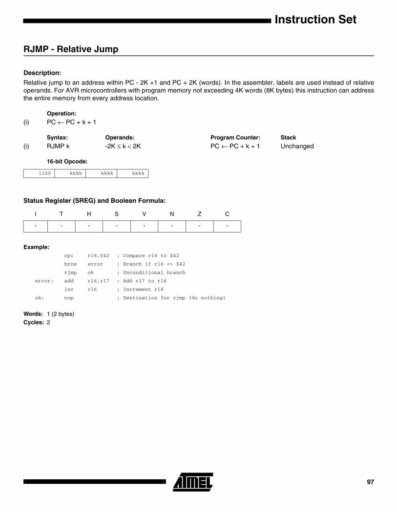
Instruction Set
RJMP - Relative Jump
Description:
Relative jump to an address within PC - 2K +1 and PC + 2K (words). In the assembler, labels are used instead of relativeoperands. For AVR microcontrollers with program memory not exceeding 4K words (8K bytes) this instruction can addressthe entire memory from every address location.
Operation:
(i) PC ← PC + k + 1
Syntax: Operands: Program Counter: Stack
(i) RJMP k -2K ≤ k < 2K PC ← PC + k + 1 Unchanged
16-bit Opcode:
Status Register (SREG) and Boolean Formula:
Example:cpi r16,$42 ; Compare r16 to $42
brne error ; Branch if r16 <> $42
rjmp ok ; Unconditional branch
error: add r16,r17 ; Add r17 to r16
inc r16 ; Increment r16
ok: nop ; Destination for rjmp (do nothing)
Words: 1 (2 bytes)Cycles: 2
1100 kkkk kkkk kkkk
I T H S V N Z C
- - - - - - - -
97

ROL - Rotate Left trough Carry
Description:
Shifts all bits in Rd one place to the left. The C flag is shifted into bit 0 of Rd. Bit 7 is shifted into the C flag. This operation,combined with LSL, effectively multiplies multi-byte signed and unsigned values by two.
Operation:
Syntax: Operands: Program Counter:
(i) ROL Rd 0 ≤ d ≤ 31 PC ← PC + 1
16-bit Opcode: (see ADC Rd,Rd)
Status Register (SREG) and Boolean Formula:
H: Rd3
S: N ⊕ V, For signed tests.
V: N ⊕ C (For N and C after the shift)
N: R7Set if MSB of the result is set; cleared otherwise.
Z: R7• R6 •R5• R4• R3 •R2• R1• R0Set if the result is $00; cleared otherwise.
C: Rd7Set if, before the shift, the MSB of Rd was set; cleared otherwise.
R (Result) equals Rd after the operation.
Example:lsl r18 ; Multiply r19:r18 by two
rol r19 ; r19:r18 is a signed or unsigned two-byte integer
brcs oneenc ; Branch if carry set
...
oneenc: nop ; Branch destination (do nothing)
Words: 1 (2 bytes)Cycles: 1
←
C ¨ b7 - - - - - - - - - - - - - - - - - - b0 ← C
0001 11dd dddd dddd
I T H S V N Z C
- - ⇔ ⇔ ⇔ ⇔ ⇔ ⇔
Instruction Set98
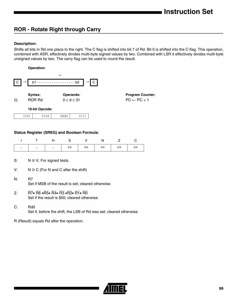
Instruction Set
ROR - Rotate Right through Carry
Description:
Shifts all bits in Rd one place to the right. The C flag is shifted into bit 7 of Rd. Bit 0 is shifted into the C flag. This operation,combined with ASR, effectively divides multi-byte signed values by two. Combined with LSR it effectively divides multi-byteunsigned values by two. The carry flag can be used to round the result.
Operation:
Syntax: Operands: Program Counter:
(i) ROR Rd 0 ≤ d ≤ 31 PC ← PC + 1
16-bit Opcode:
Status Register (SREG) and Boolean Formula:
S: N ⊕ V, For signed tests.
V: N ⊕ C (For N and C after the shift)
N: R7Set if MSB of the result is set; cleared otherwise.
Z: R7• R6 •R5• R4• R3 •R2• R1• R0Set if the result is $00; cleared otherwise.
C: Rd0Set if, before the shift, the LSB of Rd was set; cleared otherwise.
R (Result) equals Rd after the operation.
→
C → b7 - - - - - - - - - - - - - - - - - - b0 → C
1001 010d dddd 0111
I T H S V N Z C
- - - ⇔ ⇔ ⇔ ⇔ ⇔
99

Example:lsr r19 ; Divide r19:r18 by two
ror r18 ; r19:r18 is an unsigned two-byte integer
brcc zeroenc1 ; Branch if carry cleared
asr r17 ; Divide r17:r16 by two
ror r16 ; r17:r16 is a signed two-byte integer
brcc zeroenc2 ; Branch if carry cleared
...
zeroenc1: nop ; Branch destination (do nothing)
...
zeroenc1: nop ; Branch destination (do nothing)
Words: 1 (2 bytes)Cycles: 1
Instruction Set100

Instruction Set
SBC - Subtract with Carry
Description:
Subtracts two registers and subtracts with the C flag and places the result in the destination register Rd.
Operation:
(i) Rd ← Rd - Rr - C
Syntax: Operands: Program Counter:
(i) SBC Rd,Rr 0 ≤ d ≤ 31, 0 ≤ r ≤ 31 PC ← PC + 1
16-bit Opcode:
Status Register and Boolean Formula:
H: Rd3• Rr3 + Rr3• R3 + R3 •Rd3Set if there was a borrow from bit 3; cleared otherwise
S: N ⊕ V, For signed tests.
V: Rd7 •Rr7• R7 +Rd7 •Rr7 •R7Set if two’s complement overflow resulted from the operation; cleared otherwise.
N: R7Set if MSB of the result is set; cleared otherwise.
Z: R7• R6 •R5• R4• R3 •R2• R1• R0• ZPrevious value remains unchanged when the result is zero; cleared otherwise.
C: Rd7 •Rr7+ Rr7 •R7 +R7 •Rd7Set if the absolute value of the contents of Rr plus previous carry is larger than the absolute value of the Rd; clearedotherwise.
R (Result) equals Rd after the operation.
Example:; Subtract r1:r0 from r3:r2
sub r2,r0 ; Subtract low byte
sbc r3,r1 ; Subtract with carry high byte
Words: 1 (2 bytes)Cycles: 1
0000 10rd dddd rrrr
I T H S V N Z C
- - ⇔ ⇔ ⇔ ⇔ ⇔ ⇔
101
SBCI - Subtract Immediate with Carry
Description:
Subtracts a constant from a register and subtracts with the C flag and places the result in the destination register Rd.
Operation:
(i) Rd ← Rd - K - C
Syntax: Operands: Program Counter:
(i) SBCI Rd,K 16 ≤ d ≤ 31, 0 ≤ K ≤ 255 PC ← PC + 1
16-bit Opcode:
Status Register and Boolean Formula:
H: Rd3• K3 + K3• R3 + R3 •Rd3Set if there was a borrow from bit 3; cleared otherwise
S: N ⊕ V, For signed tests.
V: Rd7 •K7• R7 +Rd7 •K7 •R7Set if two’s complement overflow resulted from the operation; cleared otherwise.
N: R7Set if MSB of the result is set; cleared otherwise.
Z: R7• R6 •R5• R4• R3 •R2• R1• R0• ZPrevious value remains unchanged when the result is zero; cleared otherwise.
C: Rd7 •K7+ K7 • R7 +R7 •Rd7Set if the absolute value of the constant plus previous carry is larger than the absolute value of Rd; cleared other-wise.
R (Result) equals Rd after the operation.
Example:; Subtract $4F23 from r17:r16
subi r16,$23 ; Subtract low byte
sbci r17,$4F ; Subtract with carry high byte
Words: 1 (2 bytes)Cycles: 1
0100 KKKK dddd KKKK
I T H S V N Z C
- - ⇔ ⇔ ⇔ ⇔ ⇔ ⇔
Instruction Set102

Instruction Set
SBI - Set Bit in I/O Register
Description:
Sets a specified bit in an I/O register. This instruction operates on the lower 32 I/O registers - addresses 0-31.
Operation:
(i) I/O(A,b) ← 1
Syntax: Operands: Program Counter:
(i) SBI A,b 0 ≤ A ≤ 31, 0 ≤ b ≤ 7 PC ← PC + 1
16-bit Opcode:
Status Register (SREG) and Boolean Formula:
Example:out $1E,r0 ; Write EEPROM address
sbi $1C,0 ; Set read bit in EECR
in r1,$1D ; Read EEPROM data
Words: 1 (2 bytes)Cycles: 2
1001 1010 AAAA Abbb
I T H S V N Z C
- - - - - - - -
103

SBIC - Skip if Bit in I/O Register is Cleared
Description:
This instruction tests a single bit in an I/O register and skips the next instruction if the bit is cleared. This instruction oper-ates on the lower 32 I/O registers - addresses 0-31.
Operation:
(i) If I/O(A,b) = 0 then PC ← PC + 2 (or 3) else PC ← PC + 1
Syntax: Operands: Program Counter:
(i) SBIC A,b 0 ≤ A ≤ 31, 0 ≤ b ≤ 7 PC ← PC + 1, Condition false - no skipPC ← PC + 2, Skip a one word instructionPC ← PC + 3, Skip a two word instruction
16-bit Opcode:
Status Register (SREG) and Boolean Formula:
Example:e2wait: sbic $1C,1 ; Skip next inst. if EEWE cleared
rjmp e2wait ; EEPROM write not finished
nop ; Continue (do nothing)
Words: 1 (2 bytes)Cycles: 1 if condition is false (no skip)
2 if condition is true (skip is executed) and the instruction skipped is 1 word
3 if condition is true (skip is executed) and the instruction skipped is 2 words
1001 1001 AAAA Abbb
I T H S V N Z C
- - - - - - - -
Instruction Set104

Instruction Set
SBIS - Skip if Bit in I/O Register is Set
Description:
This instruction tests a single bit in an I/O register and skips the next instruction if the bit is set. This instruction operates onthe lower 32 I/O registers - addresses 0-31.
Operation:
(i) If I/O(A,b) = 1 then PC ← PC + 2 (or 3) else PC ← PC + 1
Syntax: Operands: Program Counter:
(i) SBIS A,b 0 ≤ A ≤ 31, 0 ≤ b ≤ 7 PC ← PC + 1, Condition false - no skipPC ← PC + 2, Skip a one word instructionPC ← PC + 3, Skip a two word instruction
16-bit Opcode:
Status Register (SREG) and Boolean Formula:
Example:
waitset: sbis $10,0 ; Skip next inst. if bit 0 in Port D set
rjmp waitset ; Bit not set
nop ; Continue (do nothing)
Words: 1 (2 bytes)Cycles: 1 if condition is false (no skip)
2 if condition is true (skip is executed) and the instruction skipped is 1 word3 if condition is true (skip is executed) and the instruction skipped is 2 words
1001 1011 AAAA Abbb
I T H S V N Z C
- - - - - - - -
105

SBIW - Subtract Immediate from Word
Description:
Subtracts an immediate value (0-63) from a register pair and places the result in the register pair. This instruction operateson the upper four register pairs, and is well suited for operations on the pointer registers.
Operation:
(i) Rd+1:Rd ← Rd+1:Rd - K
Syntax: Operands: Program Counter:
(i) SBIW Rd,K d ∈ {24,26,28,30}, 0 ≤ K ≤ 63 PC ← PC + 1
16-bit Opcode:
Status Register (SREG) and Boolean Formula:
S: N ⊕ V, For signed tests.
V: Rdh7 •R15Set if two’s complement overflow resulted from the operation; cleared otherwise.
N: R15Set if MSB of the result is set; cleared otherwise.
Z: R15• R14 •R13 •R12 •R11• R10• R9• R8• R7• R6 •R5• R4• R3 •R2• R1• R0Set if the result is $0000; cleared otherwise.
C: R15• Rdh7Set if the absolute value of K is larger than the absolute value of Rd; cleared otherwise.
R (Result) equals Rdh:Rdl after the operation (Rdh7-Rdh0 = R15-R8, Rdl7-Rdl0=R7-R0).
Example:sbiw r24,1 ; Subtract 1 from r25:r24
sbiw r28,63 ; Subtract 63 from the Y pointer(r29:r28)
Words: 1 (2 bytes)
Cycles: 2
1001 0111 KKdd KKKK
I T H S V N Z C
- - - ⇔ ⇔ ⇔ ⇔ ⇔
Instruction Set106

Instruction Set
SBR - Set Bits in Register
Description:
Sets specified bits in register Rd. Performs the logical ORI between the contents of register Rd and a constant mask K andplaces the result in the destination register Rd.
Operation:
(i) Rd ← Rd v K
Syntax: Operands: Program Counter:
(i) SBR Rd,K 16 ≤ d ≤ 31, 0 ≤ K ≤ 255 PC ← PC + 1
16-bit Opcode:
Status Register (SREG) and Boolean Formula:
S: N ⊕ V, For signed tests.
V: 0Cleared
N: R7Set if MSB of the result is set; cleared otherwise.
Z: R7• R6 •R5• R4• R3 •R2• R1• R0Set if the result is $00; cleared otherwise.
R (Result) equals Rd after the operation.
Example:sbr r16,3 ; Set bits 0 and 1 in r16
sbr r17,$F0 ; Set 4 MSB in r17
Words: 1 (2 bytes)
Cycles: 1
0110 KKKK dddd KKKK
I T H S V N Z C
- - - ⇔ 0 ⇔ ⇔ -
107

SBRC - Skip if Bit in Register is Cleared
Description:
This instruction tests a single bit in a register and skips the next instruction if the bit is cleared.
Operation:
(i) If Rr(b) = 0 then PC ← PC + 2 (or 3) else PC ← PC + 1
Syntax: Operands: Program Counter:
(i) SBRC Rr,b 0 ≤ r ≤ 31, 0 ≤ b ≤ 7 PC ← PC + 1, Condition false - no skipPC ← PC + 2, Skip a one word instructionPC ← PC + 3, Skip a two word instruction
16-bit Opcode:
Status Register (SREG) and Boolean Formula:
Example:sub r0,r1 ; Subtract r1 from r0
sbrc r0,7 ; Skip if bit 7 in r0 cleared
sub r0,r1 ; Only executed if bit 7 in r0 not cleared
nop ; Continue (do nothing)
Words: 1 (2 bytes)Cycles: 1 if condition is false (no skip)
2 if condition is true (skip is executed) and the instruction skipped is 1 word3 if condition is true (skip is executed) and the instruction skipped is 2 words
1111 110r rrrr 0bbb
I T H S V N Z C
- - - - - - - -
Instruction Set108

Instruction Set
SBRS - Skip if Bit in Register is Set
Description:
This instruction tests a single bit in a register and skips the next instruction if the bit is set.
Operation:
(i) If Rr(b) = 1 then PC ← PC + 2 (or 3) else PC ← PC + 1
Syntax: Operands: Program Counter:
(i) SBRS Rr,b 0 ≤ r ≤ 31, 0 ≤ b ≤ 7 PC ← PC + 1, Condition false - no skipPC ← PC + 2, Skip a one word instructionPC ← PC + 3, Skip a two word instruction
16-bit Opcode:
Status Register (SREG) and Boolean Formula:
Example:sub r0,r1 ; Subtract r1 from r0
sbrs r0,7 ; Skip if bit 7 in r0 set
neg r0 ; Only executed if bit 7 in r0 not set
nop ; Continue (do nothing)
Words: 1 (2 bytes)Cycles: 1 if condition is false (no skip)
2 if condition is true (skip is executed) and the instruction skipped is 1 word3 if condition is true (skip is executed) and the instruction skipped is 2 words
1111 111r rrrr 0bbb
I T H S V N Z C
- - - - - - - -
109

SEC - Set Carry Flag
Description:
Sets the Carry flag (C) in SREG (status register).
Operation:
(i) C ← 1
Syntax: Operands: Program Counter:
(i) SEC None PC ← PC + 1
16-bit Opcode:
Status Register (SREG) and Boolean Formula:
C: 1Carry flag set
Example:sec ; Set carry flag
adc r0,r1 ; r0=r0+r1+1
Words: 1 (2 bytes)
Cycles: 1
1001 0100 0000 1000
I T H S V N Z C
- - - - - - - 1
Instruction Set110
Instruction Set
SEH - Set Half Carry Flag
Description:
Sets the Half Carry (H) in SREG (status register).
Operation:
(i) H ← 1
Syntax: Operands: Program Counter:
(i) SEH None PC ← PC + 1
16-bit Opcode:
Status Register (SREG) and Boolean Formula:
H: 1Half Carry flag set
Example:seh ; Set Half Carry flag
Words: 1 (2 bytes)Cycles: 1
1001 0100 0101 1000
I T H S V N Z C
- - 1 - - - - -
111

SEI - Set Global Interrupt Flag
Description:
Sets the Global Interrupt flag (I) in SREG (status register).
Operation:
(i) I ← 1
Syntax: Operands: Program Counter:
(i) SEI None PC ← PC + 1
16-bit Opcode:
Status Register (SREG) and Boolean Formula:
I: 1Global Interrupt flag set
Example:cli ; Disable interrupts
in r13,$16 ; Read Port B
sei ; Enable interrupts
Words: 1 (2 bytes)Cycles: 1
1001 0100 0111 1000
I T H S V N Z C
1 - - - - - - -
Instruction Set112

Instruction Set
SEN - Set Negative Flag
Description:
Sets the Negative flag (N) in SREG (status register).
Operation:
(i) N ← 1
Syntax: Operands: Program Counter:
(i) SEN None PC ← PC + 1
16-bit Opcode:
Status Register (SREG) and Boolean Formula:
N: 1Negative flag set
Example:add r2,r19 ; Add r19 to r2
sen ; Set negative flag
Words: 1 (2 bytes)
Cycles: 1
1001 0100 0010 1000
I T H S V N Z C
- - - - - 1 - -
113

SER - Set all bits in Register
Description:
Loads $FF directly to register Rd.
Operation:
(i) Rd ← $FF
Syntax: Operands: Program Counter:
(i) SER Rd 16 ≤ d ≤ 31 PC ← PC + 1
16-bit Opcode:
Status Register (SREG) and Boolean Formula:
Example:clr r16 ; Clear r16
ser r17 ; Set r17
out $18,r16 ; Write zeros to Port B
nop ; Delay (do nothing)
out $18,r17 ; Write ones to Port B
Words: 1 (2 bytes)
Cycles: 1
1110 1111 dddd 1111
I T H S V N Z C
- - - - - - - -
Instruction Set114

Instruction Set
SES - Set Signed Flag
Description:
Sets the Signed flag (S) in SREG (status register).
Operation:
(i) S ← 1
Syntax: Operands: Program Counter:
(i) SES None PC ← PC + 1
16-bit Opcode:
Status Register (SREG) and Boolean Formula:
S: 1Signed flag set
Example:add r2,r19 ; Add r19 to r2
ses ; Set negative flag
Words: 1 (2 bytes)
Cycles: 1
1001 0100 0100 1000
I T H S V N Z C
- - - 1 - - - -
115

SET - Set T Flag
Description:
Sets the T flag in SREG (status register).
Operation:
(i) T ← 1
Syntax: Operands: Program Counter:
(i) SET None PC ← PC + 1
16-bit Opcode:
Status Register (SREG) and Boolean Formula:
T: 1T flag set
Example:set ; Set T flag
Words: 1 (2 bytes)Cycles: 1
1001 0100 0110 1000
I T H S V N Z C
- 1 - - - - - -
Instruction Set116

Instruction Set
SEV - Set Overflow Flag
Description:
Sets the Overflow flag (V) in SREG (status register).
Operation:
(i) V ← 1
Syntax: Operands: Program Counter:
(i) SEV None PC ← PC + 1
16-bit Opcode:
Status Register (SREG) and Boolean Formula:
V: 1Overflow flag set
Example:add r2,r19 ; Add r19 to r2
sev ; Set overflow flag
Words: 1 (2 bytes)
Cycles: 1
1001 0100 0011 1000
I T H S V N Z C
- - - - 1 - - -
117

SEZ - Set Zero Flag
Description:
Sets the Zero flag (Z) in SREG (status register).
Operation:
(i) Z ← 1
Syntax: Operands: Program Counter:
(i) SEZ None PC ← PC + 1
16-bit Opcode:
Status Register (SREG) and Boolean Formula:
Z: 1Zero flag set
Example:add r2,r19 ; Add r19 to r2
sez ; Set zero flag
Words: 1 (2 bytes)
Cycles: 1
1001 0100 0001 1000
I T H S V N Z C
- - - - - - 1 -
Instruction Set118

Instruction Set
SLEEP
Description:
This instruction sets the circuit in sleep mode defined by the MCU control register.
Operation:
Refer to the device documentation for detailed description of SLEEP usage.
Syntax: Operands: Program Counter:
SLEEP None PC ← PC + 1
16-bit Opcode:
Status Register (SREG) and Boolean Formula:
Example:mov r0,r11 ; Copy r11 to r0
ldi r16,(1<<SE) ; Enable sleep mode
out MCUCR, r16
sleep ; Put MCU in sleep mode
Words: 1 (2 bytes)Cycles: 1
1001 0101 1000 1000
I T H S V N Z C
- - - - - - - -
119

SPM - Store Program Memory
Description:
SPM can be used to erase a page in the program memory, to write a page in the program memory (that is already erased),and to set boot loader lock bits. In some devices, the program memory can be written one word at a time, in other devicesan entire page can be programmed simultaneously after first filling a temporary page buffer. In all cases, the program mem-ory must be erased one page at a time. When erasing the program memory, the Z register is used as page address. Whenwriting the program memory, the Z register is used as page or word address, and the R1:R0 register pair is used as data.When setting the boot loader lock bits, the R1:R0 register pair is used as data. Refer to the device documentation fordetailed description of SPM usage. This instruction can address the first 64K bytes (32K words) of program memory.
Operation: Comment:
(i) (Z) ← $ffff Erase program memory page(ii) (Z) ← R1:R0 Write program memory word(iii) (Z) ← R1:R0 Write temporary page buffer(iv) (Z) ← TEMP Write temporary page buffer to program memory(v) BLBITS ← R1:R0 Set boot loader lock bits
Syntax: Operands: Program Counter:
(i)-(v) SPM None PC ← PC + 1
16-bit Opcode:
Status Register (SREG) and Boolean Formula:
Example:; This example shows SPM write of one word for devices with word write
ldi r31, $F0 ; Load Z high byte
clr r30 ; Clear Z low byte
ldi r16, $CF ; Load data to store
mov r1, r16
ldi r16, $FF
mov r0, r16
ldi r16,$03 ; Enable SPM, erase page
out SPMCR, r16 ;
spm ; Erase page starting at $F000
ldi r16,$01 ; Enable SPM, store to program memory
out SPMCR, r16 ;
spm ; Execute SPM, store R1:R0 to program memory location $F000
Words: 1 (2 bytes)Cycles: depends on the operation
1001 0101 1110 1000
I T H S V N Z C
- - - - - - - -
Instruction Set120

Instruction Set
ST - Store Indirect From Register to data space using Index X
Description:
Stores one byte indirect from a register to data space. For parts with SRAM, the data space consists of the register file, I/Omemory and internal SRAM (and external SRAM if applicable). For parts without SRAM, the data space consists of the reg-ister file only. The EEPROM has a separate address space.
The data location is pointed to by the X (16 bits) pointer register in the register file. Memory access is limited to the currentdata segment of 64K bytes. To access another data segment in devices with more than 64K bytes data space, the RAMPXin register in the I/O area has to be changed.
The X pointer register can either be left unchanged by the operation, or it can be post-incremented or pre-decremented.These features are especially suited for accessing arrays, tables, and stack pointer usage of the X pointer register. Notethat only the low byte of the X pointer is updated in devices with no more than 256 bytes data space. For such devices, thehigh byte of the pointer is not used by this instruction and can be used for other purposes. The RAMPX register in the I/Oarea is updated in parts with more than 64K bytes data space.
The result of these combinations is undefined:
ST X+, r26ST X+, r27ST -X, r26ST -X, r27
Using the X pointer:
Operation: Comment:
(i) (X) ← Rr X: Unchanged(ii) (X) ← Rr X ← X+1 X: Post incremented(iii) X ← X - 1 (X) ← Rr X: Pre decremented
Syntax: Operands: Program Counter:
(i) ST X, Rr 0 ≤ r ≤ 31 PC ← PC + 1(ii) ST X+, Rr 0 ≤ r ≤ 31 PC ← PC + 1(iii) ST -X, Rr 0 ≤ r ≤ 31 PC ← PC + 1
16-bit Opcode :
Status Register (SREG) and Boolean Formula:
(i) 1001 001r rrrr 1100
(ii) 1001 001r rrrr 1101
(iii) 1001 001r rrrr 1110
I T H S V N Z C
- - - - - - - -
121

Example:clr r27 ; Clear X high byte
ldi r26,$60 ; Set X low byte to $60
st X+,r0 ; Store r0 in data space loc. $60(X post inc)
st X,r1 ; Store r1 in data space loc. $61
ldi r26,$63 ; Set X low byte to $63
st X,r2 ; Store r2 in data space loc. $63
st -X,r3 ; Store r3 in data space loc. $62(X pre dec)
Words: 1 (2 bytes)Cycles: 2
Instruction Set122

Instruction Set
ST (STD) - Store Indirect From Register to data space using Index Y
Description:
Stores one byte indirect with or without displacement from a register to data space. For parts with SRAM, the data spaceconsists of the register file, I/O memory and internal SRAM (and external SRAM if applicable). For parts without SRAM, thedata space consists of the register file only. The EEPROM has a separate address space.
The data location is pointed to by the Y (16 bits) pointer register in the register file. Memory access is limited to the currentdata segment of 64K bytes. To access another data segment in devices with more than 64K bytes data space, the RAMPYin register in the I/O area has to be changed.
The Y pointer register can either be left unchanged by the operation, or it can be post-incremented or pre-decremented.These features are especially suited for accessing arrays, tables, and stack pointer usage of the Y pointer register. Notethat only the low byte of the Y pointer is updated in devices with no more than 256 bytes data space. For such devices, thehigh byte of the pointer is not used by this instruction and can be used for other purposes. The RAMPY register in the I/Oarea is updated in parts with more than 64K bytes data space, and the displacement is added to the entire 24-bit addresson such devices.
The result of these combinations is undefined:
ST Y+, r28ST Y+, r29ST -Y, r28ST -Y, r29
Using the Y pointer:
Operation: Comment:
(i) (Y) ← Rr Y: Unchanged(ii) (Y) ← Rr Y ← Y+1 Y: Post incremented(iii) Y ← Y - 1 (Y) ← Rr Y: Pre decremented(iiii) (Y+q) ← Rr Y: Unchanged, q: Displacement
Syntax: Operands: Program Counter:
(i) ST Y, Rr 0 ≤ r ≤ 31 PC ← PC + 1(ii) ST Y+, Rr 0 ≤ r ≤ 31 PC ← PC + 1(iii) ST -Y, Rr 0 ≤ r ≤ 31 PC ← PC + 1(iiii) STD Y+q, Rr 0 ≤ r ≤ 31, 0 ≤ q ≤ 63 PC ← PC + 1
16-bit Opcode:
Status Register (SREG) and Boolean Formula:
(i) 1000 001r rrrr 1000
(ii) 1001 001r rrrr 1001
(iii) 1001 001r rrrr 1010
(iiii) 10q0 qq1r rrrr 1qqq
I T H S V N Z C
- - - - - - - -
123
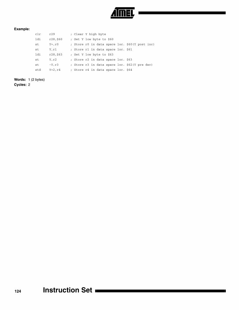
Example:clr r29 ; Clear Y high byte
ldi r28,$60 ; Set Y low byte to $60
st Y+,r0 ; Store r0 in data space loc. $60(Y post inc)
st Y,r1 ; Store r1 in data space loc. $61
ldi r28,$63 ; Set Y low byte to $63
st Y,r2 ; Store r2 in data space loc. $63
st -Y,r3 ; Store r3 in data space loc. $62(Y pre dec)
std Y+2,r4 ; Store r4 in data space loc. $64
Words: 1 (2 bytes)Cycles: 2
Instruction Set124

Instruction Set
ST (STD) - Store Indirect From Register to data space using Index Z
Description:
Stores one byte indirect with or without displacement from a register to data space. For parts with SRAM, the data spaceconsists of the register file, I/O memory and internal SRAM (and external SRAM if applicable). For parts without SRAM, thedata space consists of the register file only. The EEPROM has a separate address space.
The data location is pointed to by the Z (16 bits) pointer register in the register file. Memory access is limited to the currentdata segment of 64K bytes. To access another data segment in devices with more than 64K bytes data space, the RAMPZin register in the I/O area has to be changed.
The Z pointer register can either be left unchanged by the operation, or it can be post-incremented or pre-decremented.These features are especially suited for stack pointer usage of the Z pointer register, however because the Z pointer regis-ter can be used for indirect subroutine calls, indirect jumps and table lookup, it is often more convenient to use the X or Ypointer as a dedicated stack pointer. Note that only the low byte of the Z pointer is updated in devices with no more than256 bytes data space. For such devices, the high byte of the pointer is not used by this instruction and can be used forother purposes. The RAMPZ register in the I/O area is updated in parts with more than 64K bytes data space, and the dis-placement is added to the entire 24-bit address on such devices. For devices with more than 64K bytes program memoryand up to 64K bytes data memory, the RAMPZ register is only used by the ELPM and ESPM instructions. Hence, RAMPZis not affected by the ST instruction.
The result of these combinations is undefined:ST Z+, r30ST Z+, r31ST -Z, r30ST -Z, r31
Using the Z pointer:
Operation: Comment:
(i) (Z) ←Rr Z: Unchanged(ii) (Z) ← Rr Z ← Z+1 Z: Post incremented(iii) Z ← Z - 1 (Z) ← Rr Z: Pre decremented(iiii) (Z+q) ← Rr Z: Unchanged, q: Displacement
Syntax: Operands: Program Counter:
(i) ST Z, Rr 0 ≤ r ≤ 31 PC ← PC + 1(ii) ST Z+, Rr 0 ≤ r ≤ 31 PC ← PC + 1(iii) ST -Z, Rr 0 ≤ r ≤ 31 PC ← PC + 1(iiii) STD Z+q, Rr 0 ≤ r ≤ 31, 0 ≤ q ≤ 63 PC ← PC + 1
125
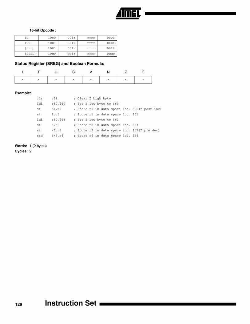
16-bit Opcode :
Status Register (SREG) and Boolean Formula:
Example:clr r31 ; Clear Z high byte
ldi r30,$60 ; Set Z low byte to $60
st Z+,r0 ; Store r0 in data space loc. $60(Z post inc)
st Z,r1 ; Store r1 in data space loc. $61
ldi r30,$63 ; Set Z low byte to $63
st Z,r2 ; Store r2 in data space loc. $63
st -Z,r3 ; Store r3 in data space loc. $62(Z pre dec)
std Z+2,r4 ; Store r4 in data space loc. $64
Words: 1 (2 bytes)Cycles: 2
(i) 1000 001r rrrr 0000
(ii) 1001 001r rrrr 0001
(iii) 1001 001r rrrr 0010
(iiii) 10q0 qq1r rrrr 0qqq
I T H S V N Z C
- - - - - - - -
Instruction Set126

Instruction Set
STS - Store Direct to data space
Description:
Stores one byte from a Register to the data space. For parts with SRAM, the data space consists of the register file, I/Omemory and internal SRAM (and external SRAM if applicable). For parts without SRAM, the data space consists of the reg-ister file only. The EEPROM has a separate address space.
A 16-bit address must be supplied. Memory access is limited to the current data segment of 64K bytes. The STS instructionuses the RAMPD register to access memory above 64K bytes. To access another data segment in devices with more than64K bytes data space, the RAMPD in register in the I/O area has to be changed.
Operation:
(i) (k) ← Rr
Syntax: Operands: Program Counter:
(i) STS k,Rr 0 ≤ r ≤ 31, 0 ≤ k ≤ 65535 PC ← PC + 2
32-bit Opcode:
Status Register (SREG) and Boolean Formula:
Example:lds r2,$FF00 ; Load r2 with the contents of data space location $FF00
add r2,r1 ; add r1 to r2
sts $FF00,r2 ; Write back
Words: 2 (4 bytes)Cycles: 2
1001 001d dddd 0000
kkkk kkkk kkkk kkkk
I T H S V N Z C
- - - - - - - -
127
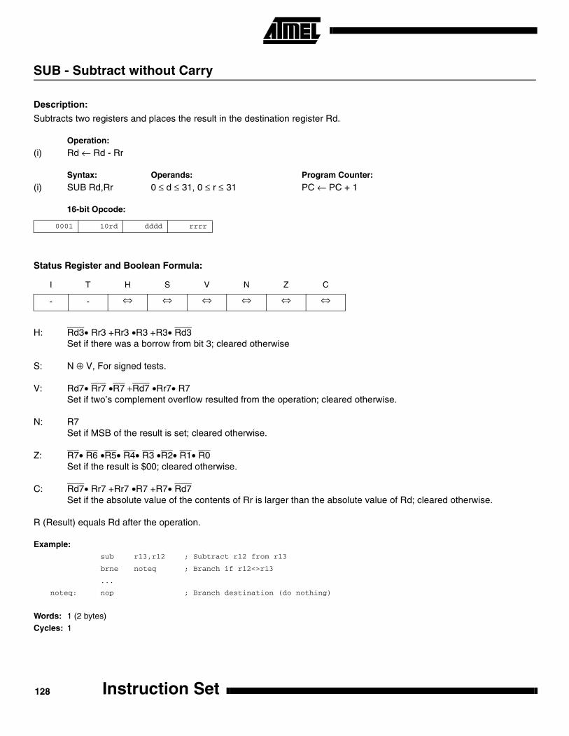
SUB - Subtract without Carry
Description:
Subtracts two registers and places the result in the destination register Rd.
Operation:
(i) Rd ← Rd - Rr
Syntax: Operands: Program Counter:
(i) SUB Rd,Rr 0 ≤ d ≤ 31, 0 ≤ r ≤ 31 PC ← PC + 1
16-bit Opcode:
Status Register and Boolean Formula:
H: Rd3• Rr3 +Rr3 •R3 +R3• Rd3Set if there was a borrow from bit 3; cleared otherwise
S: N ⊕ V, For signed tests.
V: Rd7• Rr7 •R7 +Rd7 •Rr7• R7Set if two’s complement overflow resulted from the operation; cleared otherwise.
N: R7Set if MSB of the result is set; cleared otherwise.
Z: R7• R6 •R5• R4• R3 •R2• R1• R0Set if the result is $00; cleared otherwise.
C: Rd7• Rr7 +Rr7 •R7 +R7• Rd7Set if the absolute value of the contents of Rr is larger than the absolute value of Rd; cleared otherwise.
R (Result) equals Rd after the operation.
Example:sub r13,r12 ; Subtract r12 from r13
brne noteq ; Branch if r12<>r13
...
noteq: nop ; Branch destination (do nothing)
Words: 1 (2 bytes)Cycles: 1
0001 10rd dddd rrrr
I T H S V N Z C
- - ⇔ ⇔ ⇔ ⇔ ⇔ ⇔
Instruction Set128

Instruction Set
SUBI - Subtract Immediate
Description:
Subtracts a register and a constant and places the result in the destination register Rd. This instruction is working on Reg-ister R16 to R31 and is very well suited for operations on the X, Y and Z pointers.
Operation:
(i) Rd ← Rd - K
Syntax: Operands: Program Counter:
(i) SUBI Rd,K 16 ≤ d ≤ 31, 0 ≤ K ≤ 255 PC ← PC + 1
16-bit Opcode:
Status Register and Boolean Formula:
H: Rd3• K3+K3 •R3 +R3 •Rd3Set if there was a borrow from bit 3; cleared otherwise
S: N ⊕ V, For signed tests.
V: Rd7• K7 •R7 +Rd7• K7 •R7Set if two’s complement overflow resulted from the operation; cleared otherwise.
N: R7Set if MSB of the result is set; cleared otherwise.
Z: R7• R6 •R5• R4• R3 •R2• R1• R0Set if the result is $00; cleared otherwise.
C: Rd7• K7 +K7 •R7 +R7• Rd7Set if the absolute value of K is larger than the absolute value of Rd; cleared otherwise.
R (Result) equals Rd after the operation.
Example:subi r22,$11 ; Subtract $11 from r22
brne noteq ; Branch if r22<>$11
...
noteq: nop ; Branch destination (do nothing)
Words: 1 (2 bytes)Cycles: 1
0101 KKKK dddd KKKK
I T H S V N Z C
- - ⇔ ⇔ ⇔ ⇔ ⇔ ⇔
129
SWAP - Swap Nibbles
Description:
Swaps high and low nibbles in a register.
Operation:
(i) R(7:4) ← Rd(3:0), R(3:0) ← Rd(7:4)
Syntax: Operands: Program Counter:
(i) SWAP Rd 0 ≤ d ≤ 31 PC ← PC + 1
16-bit Opcode:
Status Register and Boolean Formula:
R (Result) equals Rd after the operation.
Example:inc r1 ; Increment r1
swap r1 ; Swap high and low nibble of r1
inc r1 ; Increment high nibble of r1
swap r1 ; Swap back
Words: 1 (2 bytes)Cycles: 1
1001 010d dddd 0010
I T H S V N Z C
- - - - - - - -
Instruction Set130

Instruction Set
TST - Test for Zero or Minus
Description:
Tests if a register is zero or negative. Performs a logical AND between a register and itself. The register will remainunchanged.
Operation:
(i) Rd ← Rd • Rd
Syntax: Operands: Program Counter:
(i) TST Rd 0 ≤ d ≤ 31 PC ← PC + 1
16-bit Opcode: (see AND Rd, Rd)
Status Register and Boolean Formula:
S: N ⊕ V, For signed tests.
V: 0Cleared
N: R7Set if MSB of the result is set; cleared otherwise.
Z: R7• R6 •R5• R4• R3 •R2• R1• R0Set if the result is $00; cleared otherwise.
R (Result) equals Rd.
Example:tst r0 ; Test r0
breq zero ; Branch if r0=0
...
zero: nop ; Branch destination (do nothing)
Words: 1 (2 bytes)Cycles: 1
0010 00dd dddd dddd
I T H S V N Z C
- - - ⇔ 0 ⇔ ⇔ -
131

WDR - Watchdog Reset
Description:
This instruction resets the Watchdog Timer. This instruction must be executed within a limited time given by the WD pres-caler. See the Watchdog Timer hardware specification.
Operation:
(i) WD timer restart.
Syntax: Operands: Program Counter:
(i) WDR None PC ← PC + 1
16-bit Opcode:
Status Register and Boolean Formula:
Example:wdr ; Reset watchdog timer
Words: 1 (2 bytes)Cycles: 1
1001 0101 1010 1000
I T H S V N Z C
- - - - - - - -
Instruction Set132
© Atmel Corporation 1999.Atmel Corporation makes no warranty for the use of its products, other than those expressly contained in the Company’s standard war-ranty which is detailed in Atmel’s Terms and Conditions located on the Company’s web site. The Company assumes no responsibility forany errors which may appear in this document, reserves the right to change devices or specifications detailed herein at any time withoutnotice, and does not make any commitment to update the information contained herein. No licenses to patents or other intellectual prop-erty of Atmel are granted by the Company in connection with the sale of Atmel products, expressly or by implication. Atmel’s products arenot authorized for use as critical components in life support devices or systems.
Atmel Headquarters Atmel Operations
Corporate Headquarters2325 Orchard ParkwaySan Jose, CA 95131TEL (408) 441-0311FAX (408) 487-2600
EuropeAtmel U.K., Ltd.Coliseum Business CentreRiverside WayCamberley, Surrey GU15 3YLEnglandTEL (44) 1276-686-677FAX (44) 1276-686-697
AsiaAtmel Asia, Ltd.Room 1219Chinachem Golden Plaza77 Mody Road TsimhatsuiEast KowloonHong KongTEL (852) 2721-9778FAX (852) 2722-1369
JapanAtmel Japan K.K.9F, Tonetsu Shinkawa Bldg.1-24-8 ShinkawaChuo-ku, Tokyo 104-0033JapanTEL (81) 3-3523-3551FAX (81) 3-3523-7581
Atmel Colorado Springs1150 E. Cheyenne Mtn. Blvd.Colorado Springs, CO 80906TEL (719) 576-3300FAX (719) 540-1759
Atmel RoussetZone Industrielle13106 Rousset CedexFranceTEL (33) 4-4253-6000FAX (33) 4-4253-6001
Fax-on-DemandNorth America:1-(800) 292-8635
International:1-(408) 441-0732
Web Sitehttp://www.atmel.com
BBS1-(408) 436-4309
Printed on recycled paper.
0856B–06/99/xM
Marks bearing ® and/or ™ are registered trademarks and trademarks of Atmel Corporation.
Terms and product names in this document may be trademarks of others.