autonomous robotic boat platform - bradley...
TRANSCRIPT

Autonomous Robotic Boat Platform
Authors: Darren McDannald, Leah Cramer, Noah Dupes, and Ryan Burke
Advisors: Mr. Nick Schmidt, Dr. José Sánchez, and Dr. Gary Dempsey
April 30th, 2014

i
Abstract An autonomous robotic boat platform was proposed as the design team’s capstone project in expectation
of competing in the 2015 Association for Unmanned Vehicles Systems International (AUVSI) RoboBoat
competition. Practical applications of this project include naval reconnaissance, hazardous rescue, marine
research and exploration. The boat platform was designed to meet competition requirements and
constraints, while remaining within the $1500 budget provided by Bradley University Department of
Electrical and Computer Engineering. The primary project expenses include the boat frame, circuitry,
sensors, and propellers; hardware was reused from past RoboBoat teams to save on costs. The developed
subsystems include coordinate navigation using Global Positioning System (GPS) and compass sensors,
remote control using a radio control system, central processing using a dual-core processor, motor control
using commutation drivers and brushless direct current (DC) motors, and visual navigation using circle
and blob detection. These subsystems were programmed, debugged, and interfaced using Inter-Integrated
Circuit (I2C), Serial Peripheral Interface (SPI), Joint Test Action Group (JTAG) and serial
communication. The system was never fully integrated, but all subsystems' functionalities were
effectively proven utilizing tests that mimicked fully integrated system conditions. Remaining work such
as integration of the system and parameter testing in water is discussed.

ii
Table of Contents
I. Introduction and Overview ................................................................................................................... 1
A. Problem Background ........................................................................................................................ 1
B. Problem Statement ............................................................................................................................ 1
C. Constraints of the Solution ................................................................................................................ 1
II. Statement of Work ................................................................................................................................ 2
A. Nonfunctional Requirements ............................................................................................................ 2
B. Functional Requirements .................................................................................................................. 3
C. Design Overview .............................................................................................................................. 4
i. System Block Diagram ................................................................................................................ 4
ii. Subsystem Block Diagram/Flow Chart ......................................................................................... 4
iii. High-level Flowchart .................................................................................................................... 7
iv. Division of Labor .......................................................................................................................... 8
v. Hardware ....................................................................................................................................... 8
vi. Software ........................................................................................................................................ 9
D. Economic Analysis ......................................................................................................................... 13
III. Design Testing and Validation .......................................................................................................... 13
IV. Conclusions........................................................................................................................................ 15
V. References .......................................................................................................................................... 16
VI. Appendices ......................................................................................................................................... 17
Appendix A: Circuit Schematics............................................................................................................. 17
Appendix B: Motor Calculations ............................................................................................................ 19
Appendix C: Theory of Operation .......................................................................................................... 23

iii
Table of Figures
Fig. 1. Overall system block diagram ........................................................................................................... 4
Fig. 2. GPS/compass subsystem block diagram ........................................................................................... 4
Fig. 3 CPU subsystem high-level flowchart ................................................................................................. 5
Fig. 4 Visual navigation subsystem software flowchart ............................................................................... 6
Fig. 5 Remote control subsystem block diagram .......................................................................................... 6
Fig. 6 Motor control subsystem block diagram ............................................................................................ 7
Fig. 7 Overall system flowchart .................................................................................................................... 7
Table of Tables
TABLE I ROBOBOAT COMPETITION CONSTRAINTS .................................................................................... 2
TABLE II SYSTEM NON-FUNCTIONAL REQUIREMENTS ............................................................................... 3
TABLE III SYSTEM SPECIFICATIONS ........................................................................................................... 3
TABLE IV PROJECT DIVISION OF LABOR .................................................................................................... 8
TABLE V PROJECT EXPENDITURES ........................................................................................................... 13
TABLE VI HOUGH TRANSFORM BUOY DETECTION ACCURACY .............................................................. 14

1
I. Introduction and Overview Autonomous robotics are an area of increased attention. The RoboBoat competition is an event that seeks
to develop interest and knowledge in autonomous aquatic robotics. The proposed autonomous robotic
boat platform is designed with RoboBoat competition requirements and constraints in mind to maintain
competition eligibility.
A. Problem Background
Autonomous robotics has been gaining notoriety and popularity in recent years. One of the driving factors
of this change has been the Google Maps car; this self-controlled vehicle demonstrates the versatility of
modern technology while maintaining user safety. Autonomous vehicles are not limited to land, however,
there is a growing demand for aquatic, autonomous platforms. These platforms can be utilized for naval
reconnaissance, hazardous rescue, and marine research & exploration. Completion of such operations
requires the use of highly technical areas of electrical engineering such as, but not limited to, electro-
mechanical systems, power electronics, computer science, communications, image processing, and
embedded systems. These are the areas and applications that the Association for Unmanned Vehicles
International (AUVSI) seeks to develop through the RoboBoat Competition. The RoboBoat Competition
is an annual contest in which autonomous surface vehicles (ASVs) created by students from across the
world attempt to complete a series of tasks and missions. Traditionally, the missions have consisted of
thermal and visual recognition, locating shore based targets, and locating and pressing a correct button
based upon a specific environmental setup; recently, the missions have transitioned into a more
technological basis (underwater light identification, acoustic beacon positioning, automated docking,
obstacle avoidance.) Successful completion of these tasks is such a feat of engineering ability that
prestigious groups and companies such as the Office of Naval Research, Northrup Grumman, and
MathWorks sponsor the competition and use it to search for future employees.
Two teams of students from Bradley University have competed in the RoboBoat competition in the past.
In 2012, seniors Jeremy Borgman and Terry Max Christy placed eighth out of sixteen contenders during
Bradley University's first attempt at the competition [1]. In 2013, seniors Zach Knoll and Steven Blass
placed fifth, winning $1,500 [2].
B. Problem Statement
Because the RoboBoat competition is held in July, a competition-ready platform is not proposed. Instead,
a simpler, versatile, robust system is proposed. This system meets the RoboBoat competition constraints
and requirements and is capable of performing some of the most basic competition tasks such as GPS
navigation, object detection, and remote controllability. This platform can be further developed after the
completion of the design team’s capstone project until the system is capable of competing in the
RoboBoat competition
C. Constraints of the Solution
As stated above, the ASV was designed to meet all constraints provided by the RoboBoat competition
guidelines, as shown in Table 1. Most of these constraints are necessary for the design of any ASV: the
ASV must be an appropriate size for the body of water, the ASV must be an appropriate weight for its
size to achieve buoyancy, the ASV must be transportable and deployable so that it can be used in the body
of water, and the ASV must not receive instruction while in autonomous mode. Some constraints, such as

2
the kill switches, the covers for dangerous parts, and an internal power source, are required by the IEEE
Code of Ethics and the NSPE Code of Ethics for Engineers to ensure safety. The only constraint provided
by Bradley University was that the project's cost must remain within a $1500 budget.
TABLE I ROBOBOAT COMPETITION CONSTRAINTS
II. Statement of Work System nonfunctional requirements are identified as reliability, stability, easy testability, easy
configurability, and efficiency. System functional requirements are identified as coordinate navigation,
propulsion, remote control, ambient operating temperature, surface buoyancy, and visual navigation. An
overall system is designed to meet the listed constraints and requirements, with subsystems to perform
specific tasks. The hardware, software, and interfacing designs of the system are described and further
subdivided into subsystems for better understanding of system compartmentalization.
A. Nonfunctional Requirements
The ASV was designed with five main objectives in mind that the design team believed most crucial to
the success of the senior capstone project. These objectives are stability, reliability, easy testability, easy
configurability, and efficiency. Stability prevents the ASV from causing irreparable damage to itself or its
surroundings. Reliability allows the ASV to consistently achieve its goals. Easy testability makes
debugging the system easier. Easy configurability allows the design team to adjust parameters quickly.
Efficiency allows the ASV to effectively utilize its limited power source. The success with which each of
these objectives was met is measured by how well each subsystem exhibits that objective. Table 2
summarizes the information provided above.
Buoyancy The vehicle must be positively buoyant and be buoyant for at least 30 minutes in water.
Communication The vehicle cannot send information or receive instruction while in autonomous mode.
Deployable The vehicle must have its own 3 or 4 point harness for crane deployment.
Energy source The vehicle must use self-contained electrical sources. Sailboats are permitted.
Kill switchThe vehicle must have at least one 4 cm diameter red button located on the vehicle that,
when actuated must disconnect power from all motors and actuators.
e-Kill switchIn addition to the physical kill-switch, the vehicle must have at least one remote kill switch
that provides the same functionality.
Payload The vehicle must have a place to mount a payload up to a 1.5 m cube weighting up to 7 kg.
Payload location The payload must have an unobstructed view of the sky and front of the vehicle.
Safety All sharp, point, moving, sensitive, etc. parts must be covered and clearly identified.
Size The vehicle must fit within a 2 m long, by 1 m, by 1 m high "box".
Towable The vehicle must have designated tow points and a tow harness installed at all times.
Weight The vehicle must be 73 kg or less.
Constraints

3
TABLE II SYSTEM NON-FUNCTIONAL REQUIREMENTS
B. Functional Requirements
As previously stated, the ASV was designed to meet the most basic competition functionalities. The
functionalities identified by the design team were Global Positioning System (GPS) navigation, remote
control, propulsion, ambient temperature operation, and visual navigation. GPS navigation describes the
ability of the ASV to travel from its current GPS coordinate to a second GPS coordinate. The ASV should
be able to arrive within 5 m of its destination after starting off facing any direction. Remote control
describes the ASV’s ability to be operated remotely. The ASV should be controllable at distances greater
than 100 m to ensure the signal will reach all parts of the competition lake. Propulsion describes the
ability of the ASV to propel itself in a given direction. The design team used data from previous
RoboBoat teams to calculate thrust and power draw values that would provide appropriate movement
speed and battery life to the ASV. Ambient temperature operation describes the ASV’s ability to maintain
stable operation in a wide range of temperatures. The ASV should be able to operate between 0°C and
45°C to account for possible competition conditions. Finally visual navigation describes the ability of the
ASV to utilize a camera to identify objects and use that information to control the ASV’s movements. The
ASV should be capable of identifying individual and pairs of buoys according to the specifications
provided by the RoboBoat competition guidelines. All of the functional requirements and specifications
are shown in Table 3.
TABLE III SYSTEM SPECIFICATIONS
Non-functional requirements Metrics
Reliability % of reliable subsystems
Stability % of stable subsystems
Easy testability % of easily testable subsystems
Easy configurability % of easily configurable subsystems
Efficiency % of efficient subsystems
ASV starting angle ±180°
Destination accuracy < 5 m
Thrust > 27 N
Power draw < 120 A·h within 30 minutes
Remote-controllable Distance 100m
Surface Submersion 50% > x > ~0%
Maximum 45 °C
Minimum 0 °C
Buoy size A-1 (Diameter x length: 27.9 x 38.1 cm, Circumference: 91.1 cm)
Buoy shape Spherical, cylindrical
Buoy gate distance 0.914-6.096 m
Buoy gate width 1.524 - 1.829 m
Buoy midpoint angles < 46 degrees
Buoy color red & green
Number of gates > 2
Time limit 5 min.
Specifications
Coordinate
navigation
Propulsion
Ambient operating
temperature
Visual navigation

4
C. Design Overview
i. System Block Diagram
Using the functional requirements, non-functional requirements, and constraints a system is designed to
elegantly complete the outlined tasks.
Fig. 1. Overall system block diagram
ii. Subsystem Block Diagram/Flow Chart
a. GPS/Compass Subsystem
As shown in the subsystem block diagram below, Fig. 2, the GPS/compass subsystem consists of three
units: a GPS sensor (FGPMMOPA6H), a compass sensor (CMPS10), and a microcontroller
(Atmega1284P). The microcontroller communicates with the GPS sensor through serial, the compass
sensor through Inter-integrated Circuit (I2C) communication, and the processor through serial
communication.
Fig. 2. GPS/compass subsystem block diagram
b. CPU Subsystem

5
A central processing unit (CPU) subsystem is necessary to receive sensor data, execute computer vision
software, and make high level decisions about the boat's movement. The CPU receives GPS and compass
data from the GPS/compass subsystem. This data, in conjunction with the visual navigation buoy
detection data, is used by the high level navigation software implemented on the CPU to determine the
appropriate speed of each motor. These motor commands are sent from the CPU and passed on to the
motor control subsystem, where each motor is activated as requested. The CPU subsystem also keeps data
associated with each boat trial organized for later review. The flowchart below outlines the basic
functions of the CPU subsystem while the boat is in operation.
Fig. 3 CPU subsystem high-level flowchart
c. Visual Navigation Subsystem
In the AUVSI competition buoy pairs are placed in the lake course as obstacles that must be passed
through, and cannot be simply avoided or travelled around. The buoy pairs are comprised of one red and
one green buoy. The red buoys are placed on the left-hand side of the competition course and the green
buoys placed on the right-hand side of the course. The computer vision subsystem is primarily
responsible for the detection of these buoys, and providing a heading to properly navigate through them.
This function is performed by first grabbing an image of the direction the boat is facing. Next, all buoys
in the frame are identified and their color analyzed. Finally, buoy pairs are formed, and navigation

6
decisions are made. All this information is then stored for analysis. This process is outlined in Fig. 3
below.
Fig. 4 Visual navigation subsystem software flowchart
d. Remote Control Subsystem
AUVSI RoboBoat competition guidelines require that all boats have the ability to be switched out of
autonomous mode and remotely controlled. In order to meet this competition requirement a remote
control (RC) subsystem was designed to receive data from a small wireless controller so that data can be
converted to motor signals. The block diagram in figure 3 shows the hardware design of the RC
subsystem. The RC subsystem consists of two parts: an RC receiver (Futaba R617FS) and an 8-bit
microcontroller (Atmega168a). The microcontroller receives the RC data by measuring pulse widths from
the RC receiver, and receives data from the central processing unit using serial communication. The RC
receiver also sends data to the motor controller using serial communication.
Fig. 5 Remote control subsystem block diagram
7
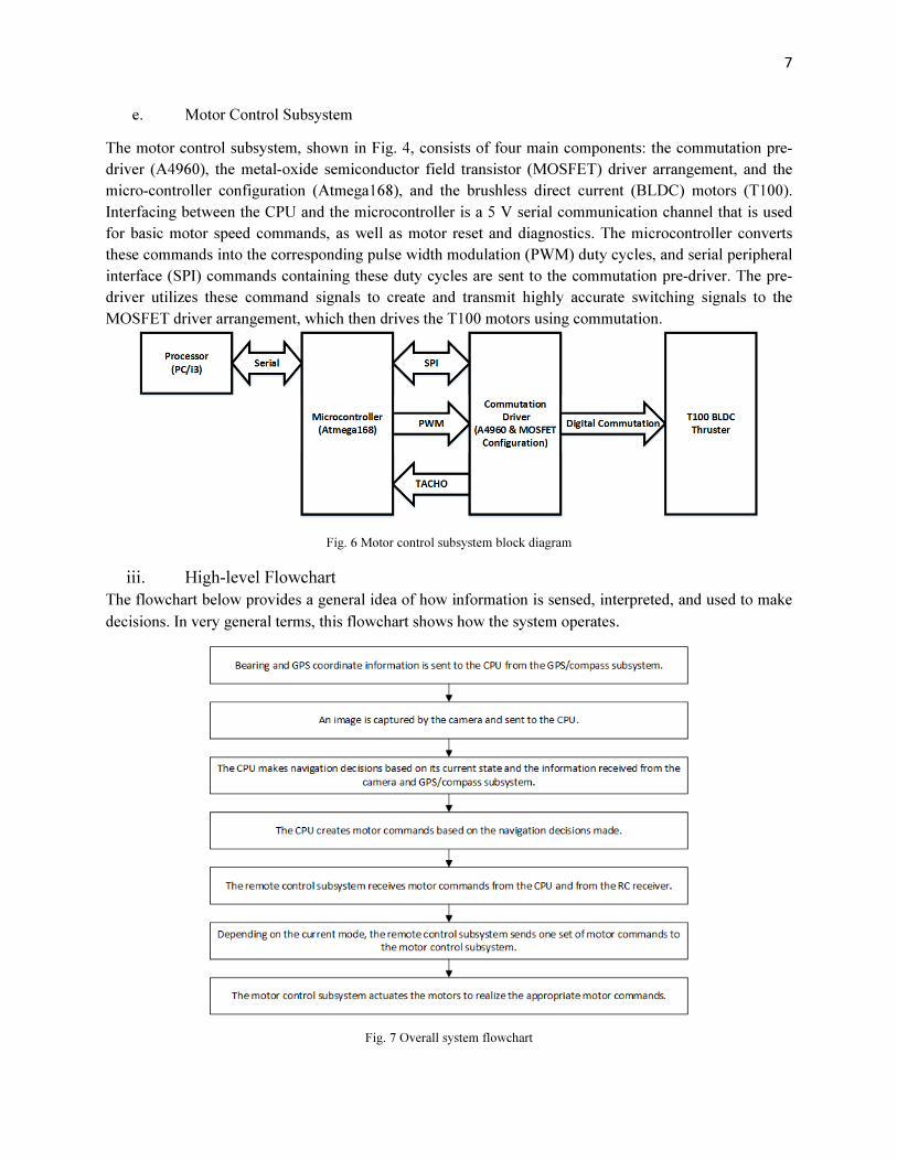
e. Motor Control Subsystem
The motor control subsystem, shown in Fig. 4, consists of four main components: the commutation pre-
driver (A4960), the metal-oxide semiconductor field transistor (MOSFET) driver arrangement, and the
micro-controller configuration (Atmega168), and the brushless direct current (BLDC) motors (T100).
Interfacing between the CPU and the microcontroller is a 5 V serial communication channel that is used
for basic motor speed commands, as well as motor reset and diagnostics. The microcontroller converts
these commands into the corresponding pulse width modulation (PWM) duty cycles, and serial peripheral
interface (SPI) commands containing these duty cycles are sent to the commutation pre-driver. The pre-
driver utilizes these command signals to create and transmit highly accurate switching signals to the
MOSFET driver arrangement, which then drives the T100 motors using commutation.
Fig. 6 Motor control subsystem block diagram
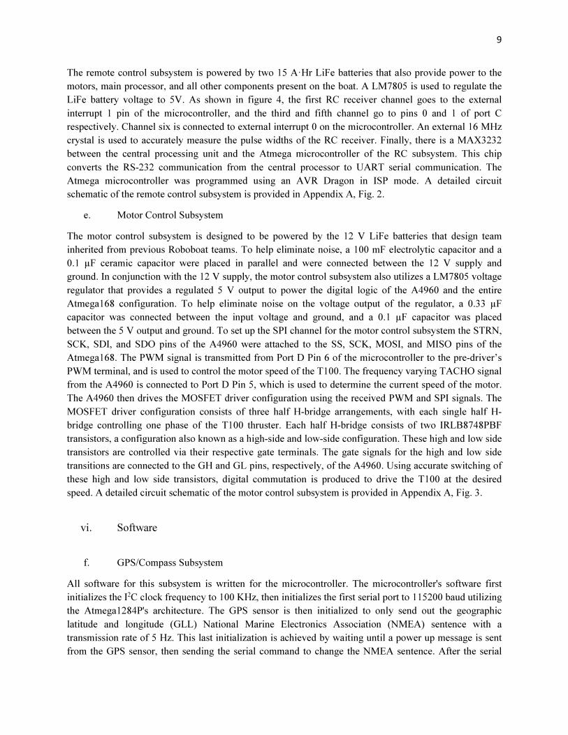
iii. High-level Flowchart
The flowchart below provides a general idea of how information is sensed, interpreted, and used to make
decisions. In very general terms, this flowchart shows how the system operates.
Fig. 7 Overall system flowchart

8
iv. Division of Labor
Table IV below shows the division of labor for the 2015 RoboBoat senior capstone project. The first
names below refer to Darren McDannald, Leah Cramer, Ryan Burke, and Noah Dupes.
TABLE IV PROJECT DIVISION OF LABOR
v. Hardware
a. GPS/Compass Subsystem
The entire subsystem is powered with the 5 V output from a single LM7805. The GPS sensor is
connected to the second set of the microcontroller's serial pins, which are configured as a pull-up network
to account for the 3.3 V output of the GPS sensor. The compass sensor is connected to the
microcontroller's I2C-compatible two-wire serial interface. Resistors (1.8 kΩ) are used to pull the I2C
lines low according to the bus capacitance and the operation frequency. A button is connected to port A
pin 0 of the microcontroller for configuring the compass sensor. The microcontroller is programmed with
an AVR Dragon using the Joint Test Action Group (JTAG) interface. The microcontroller also utilizes an
external 16 MHz crystal for a more accurate time base. The microcontroller's first set of serial pins are
connected to a MAX3232, which is used to convert the transistor-transistor logic (TTL) output of the
microcontroller to RS-232, so that the processor can interpret the messages sent. Finally, all ground pins
are tied to the same ground. All this information is shown in the GPS/compass subsystem circuit
schematic in Appendix A, Fig. 1.
b. CPU Subsystem
The RoboBoat’s main processor is an Intel i3-2120T processor with 2 cores and 4-way multitasking
processing at 2.6 GHz. This processor is mounted on a JetWay JNF9A-Q67 Mini ITX Intel Motherboard
with 2 serial ports and supported by 2 4 GB DDR3 G. SKILL Ripjaws, a 256 GB OCV Vertex SATA III
MLC Internal Solid State Drive, and a Habey HB-LR1005-120W 12 V DC-DC ATX Fanless mini-ITX
Power Supply Module.
c. Visual Navigation
The visual navigation subsystem is implemented on the main CPU, an i3 processor. Images of the boat's
environment are taken by an HP KQ246AA webcam and sent to the main CPU via USB for processing.
d. Remote Control Subsystem
Central Processing Darren
Image processing Leah
GPS/compass interfacing Ryan
Navigation Darren, Ryan
Motor control Noah
Remote control Darren
Division of labor
9
The remote control subsystem is powered by two 15 A·Hr LiFe batteries that also provide power to the
motors, main processor, and all other components present on the boat. A LM7805 is used to regulate the
LiFe battery voltage to 5V. As shown in figure 4, the first RC receiver channel goes to the external
interrupt 1 pin of the microcontroller, and the third and fifth channel go to pins 0 and 1 of port C
respectively. Channel six is connected to external interrupt 0 on the microcontroller. An external 16 MHz
crystal is used to accurately measure the pulse widths of the RC receiver. Finally, there is a MAX3232
between the central processing unit and the Atmega microcontroller of the RC subsystem. This chip
converts the RS-232 communication from the central processor to UART serial communication. The
Atmega microcontroller was programmed using an AVR Dragon in ISP mode. A detailed circuit
schematic of the remote control subsystem is provided in Appendix A, Fig. 2.
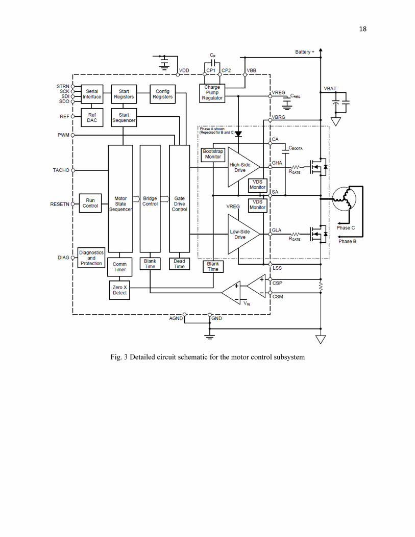
e. Motor Control Subsystem
The motor control subsystem is designed to be powered by the 12 V LiFe batteries that design team
inherited from previous Roboboat teams. To help eliminate noise, a 100 mF electrolytic capacitor and a
0.1 µF ceramic capacitor were placed in parallel and were connected between the 12 V supply and
ground. In conjunction with the 12 V supply, the motor control subsystem also utilizes a LM7805 voltage
regulator that provides a regulated 5 V output to power the digital logic of the A4960 and the entire
Atmega168 configuration. To help eliminate noise on the voltage output of the regulator, a 0.33 µF
capacitor was connected between the input voltage and ground, and a 0.1 µF capacitor was placed
between the 5 V output and ground. To set up the SPI channel for the motor control subsystem the STRN,
SCK, SDI, and SDO pins of the A4960 were attached to the SS, SCK, MOSI, and MISO pins of the
Atmega168. The PWM signal is transmitted from Port D Pin 6 of the microcontroller to the pre-driver’s
PWM terminal, and is used to control the motor speed of the T100. The frequency varying TACHO signal
from the A4960 is connected to Port D Pin 5, which is used to determine the current speed of the motor.
The A4960 then drives the MOSFET driver configuration using the received PWM and SPI signals. The
MOSFET driver configuration consists of three half H-bridge arrangements, with each single half H-
bridge controlling one phase of the T100 thruster. Each half H-bridge consists of two IRLB8748PBF
transistors, a configuration also known as a high-side and low-side configuration. These high and low side
transistors are controlled via their respective gate terminals. The gate signals for the high and low side
transitions are connected to the GH and GL pins, respectively, of the A4960. Using accurate switching of
these high and low side transistors, digital commutation is produced to drive the T100 at the desired
speed. A detailed circuit schematic of the motor control subsystem is provided in Appendix A, Fig. 3.
vi. Software
f. GPS/Compass Subsystem
All software for this subsystem is written for the microcontroller. The microcontroller's software first
initializes the I2C clock frequency to 100 KHz, then initializes the first serial port to 115200 baud utilizing
the Atmega1284P's architecture. The GPS sensor is then initialized to only send out the geographic
latitude and longitude (GLL) National Marine Electronics Association (NMEA) sentence with a
transmission rate of 5 Hz. This last initialization is achieved by waiting until a power up message is sent
from the GPS sensor, then sending the serial command to change the NMEA sentence. After the serial

10
command is sent, the microcontroller waits until it receives an acknowledge message from the GPS. If the
acknowledge message confirms that the change was made the code continues. If not, the serial command
is resent and the process repeats. Once the NMEA sentence has been changed, the process is repeated for
the transmission rate. Finally port A pin 0 of the microcontroller is set to input with a pull up resistor
active.
The main loop of the code uses the compass' I2C commands to read the bearing from the sensor. The
bearing is then stored in a moving average filter. The filter output is stored in a variable. Next, the
microcontroller waits until it receives a message from the GPS. This message is stored in a buffer, which
is then checked for accuracy using the string's checksum. If the checksum is proved accurate, then the
string is parsed into six values: latitude degrees, minutes, and minutes' decimals & longitude degrees,
minutes, and minutes' decimals. Each of those six values are then stored in separate buffers. Finally the
main loop checks if port A pin 0 is pulled low. If it is, the compass calibration mode is entered. This
function sends a distinct I2C message to the compass sensor every time the debounce button is pressed.
After the message has been sent 5 times the code returns to the main.
Apart from the initialization and main loop, two interrupt vectors are utilized in the microcontroller code.
The first interrupt sends the bearing and GPS data over serial to the processor upon receiving a message
from the processor. The second interrupt is used during GPS initialization; it receives the serial message
from the GPS sensor, verifies that an acknowledge message was sent and if so whether or not it was
completed, or if the GPS has been powered up. The interrupt sets global variables to allow the code to
utilize its findings.
g. CPU Subsystem
The central processing unit subsystem acquires data from the camera and GPS/compass subsystem, and
processes that information and converts it into commands for the actuators. This subsystem will also be
responsible for saving all of the images taken during each run, and converting them into a video and
saving it for testing purposes. The file system provided by the operating system will also be utilized to
store all the source code, libraries, configuration files, object files, and helpful documents. In tandem with
the folders for these different files there is also a make file that will build the project. The make file cut
down on compile times, because if a change was made in the main file it would not have to rebuild all of
the source code in the libraries. This was a necessity, because a compiling all of the source code could
take a few minutes, and if a minor change was made, this time would add up quite a bit and cause us to
lose unnecessary time.
The navigation code for the CPU uses a GPS coordinate stored in memory and the bearing and GPS
information sent to the CPU from the GPS/compass subsystem. The navigation code runs until the
distance from the ASV to its destination is less than 3 m. The code first resets all motor commands. It
then calculates the shortest turn that will make it face its destination. Motor commands are sent out to turn
the ASV until its current bearing is within ±20° of the desired bearing. While the current bearing remains
within that range the ASV moves forward until its current location is within 3 m of its destination.
h. Visual Navigation Subsystem
OpenCV, an open source computer vision library primarily designed for use with C++, was used to aid in
the development of the visual navigation system. Without the use of OpenCV, which provides functions

11
for basic computer vision operations, the visual navigation system would have required more
development time and manpower than was available within the RoboBoat team.
Figure 4 outlines the basic steps executed to process images taken by the camera. The first step in the
visual navigation code is to initialize the necessary image processing and camera settings. Using OpenCV
functions, video frames from the camera are grabbed, and later saved to a video file, which can be
reviewed at a later time. After the most recent video frame is grabbed from the camera, it is converted to
an OpenCV object so that it can be more easily processed. Before any further processing is done the video
frame is reduced to approximately 70% of its original size. By reducing the region of interest to include
only the lower portion of the frame, the time to process the frame is greatly reduced and the number of
erroneously detected buoys is also lowered. Because all buoys and obstacles are within the water, the sky
and trees (the upper portion of the image) can be completely ignored. The frame is then converted from
standard red-blue-green (RBG) to hue saturation value (HSV) color space. Next, two different methods of
buoys detection may be chosen: circle detection or blob detection.
First the circle detection method will be discussed. The detection of circular objects in the image is made
possible by the use of the Hough transform. OpenCV has a function that implements the Hough
Transform- this function was used in the visual navigation code. The Hough Transform searches for
circular objects in a black and white image that are within a certain radius range. Additionally, the Hough
Transform function can be modified to either increase or decrease its sensitivity (i.e. detect more or less
circular objects). In order to use the Hough Transform function the image is first converted to a grayscale
image, put through a Gaussian filter, and has Canny Edge detection applied to it. The Gaussian filter blurs
the image and reduces sharp edges in the image, which improves the performance of the edge detection.
The edge detection function returns a black and white image which contains only the edges that were
detected in the frame. This image is then passed to the Hough Transform function, which determines
whether any of the edges form a circle.
A second method of buoy detection uses blob detection. Blob detection is implemented in OpenCV as a
function that searches an image for similarly colored groups, or blobs, of pixels with the assumption that
these groups of pixels probably form an object of some sort. The blob detection function does not depend
on the circularity of the object (unlike the Hough Transform) which in theory makes it more likely to
detect buoys even when they do not appear completely circular.
After all buoys are detected the Visual Navigation code must determine which buoys are buoy pairs, and
then find the midpoint between the buoys. In order to determine which buoys are pairs all possible buoy
combinations are considered. For every combination of two buoys, the pixel locations of the each buoy
are compared to each other. If the buoy centers are at approximately the same height (i.e. at the same y-
axis value) and have similar radius sizes then it is likely that they are a buoy pair. Additionally the color
of each buoy is calculated and checked to ensure that the buoy pair contains one red and one green buoy.
If multiple buoy pairs are found then only the closest pair (the pair with the largest radius) is considered.
The midpoint between the two buoys is then calculated and the video frame is marked with the locations
of the buoys, the connecting line between the buoy pair and two directional lines. The first line indicates
the current facing direction of the boat, which is always straight ahead, and the desired direction of the
boat, which is drawn from the bottom center of the frame to the buoy midpoint. The angular difference
between these two lines can then be used to turn the boat to the correct orientation and pass through the
buoy pair.

12
In the event that only one buoy is detected a false buoy is drawn in as an approximation. The location of
the buoy within the frame and the color of the buoy determines the color of the missing buoy and which
side of the detected buoy the false buoy should be placed. Because the boat has only one camera there is a
limited range of vision and at some orientations the boat may only be able to see one buoy. To prevent the
boat from going off course, it is important to have a procedure to approximate the location of the missing
buoy.
After all buoys and buoy pairs are detected and the directional lines are determined, the current image is
written to a video file and the buoy pair locations and directional lines are ready to be returned to the
higher level navigation code, which will convert this information to motor commands.
i. Remote Control Subsystem
The RC subsystem serves three main purposes: acquire information from the central processing unit,
switch between RC and autonomous mode, and kill power to all actuators remotely. Using the
Atmega168a’s architecture, the serial port was set up to send data at a 115,200 baud rate. To measure the
pulse widths of each channel, a 16-bit timer was used in a free running loop to get a time step of
approximately 1.5 milliseconds. The next step was to setup the interrupt for channel six. This channel is
unique from other channels, because it has to be read individually, and cannot be read at the same time as
other channels. External interrupt 0 was used to read the pulse width, and check for rising and falling
edges. Channel six was used as the kill switch for the boat. Channel one used external interrupt 1 and only
checked for a rising edge to start the chain reaction of reads from the other channels. Lastly, the pin
change interrupt is enabled for the first to pins on port c for channels three and five of the RC Receiver.
The main loop consists of reading the pulse widths of the 6 channels, and checking to see which mode the
boat should be in. If the boat is set to autonomous mode it should read in the values from the central
processing unit and then relay them to the motor controller. However, if the boat is in RC mode, it takes
the processed data from channels one through four and converts them to motor commands and sends them
to the motor controller. During this process the loop is constantly checking channel six to ensure that the
kill switch has not been engaged. If it has been engaged power to the actuators will be cut immediately.
j. Motor Control Subsystem
The software of the motor control subsystem was developed in C and was written for implementation on a
single Atmega168 microcontroller. The motor control software first initializes the necessary ports and
pins of the microcontroller, setting a baud rate of 9600 bits/s for the TTL serial communication, and
initializing SPI communication using the specifications provided by the A4960 pre-driver. The
microcontroller code then transmits the corresponding A4960 configuration register values to the A4960
over SPI. These configuration register values are used to set up the output parameters of the commutation
pre-driver. The microcontroller program then waits until the ASCII character ‘M’ is received via serial
communication from the central processing unit(CPU). Once the ‘M’ character is received, the ASCII
character string is then recorded until either a semi-colon character,’;’, is received or the string length
exceeds 30 characters. The recorded string is processed to ensure that the string is of the correct length,
has the correct character structure and that the motor command values are within the range of 0-100. If all
these parameters are met, the program changes the corresponding motor’s PWM duty cycle to the desired
motor command value, as received by the CPU. Currently, the motor configuration is only designed to
drive a single T100 BLDC, therefore only one PWM signal is being set and modified within the program.

13
While waiting for motor commands from the CPU, the program executes safety features that include a
reset character string that sets all of the transmitted PWM duty cycles to 0, and a diagnostic character
string that uses SPI communication to return the flags triggered within the A4960’s diagnostic register.
D. Economic Analysis
From an economic standpoint, the design team was able to maintain the proposed budget of $1500. Even
though circuity and motor expenses exceeded the proposed amount, the overall system expense was
$1100, as shown in Table 5.
TABLE V PROJECT EXPENDITURES
III. Design Testing and Validation
A. GPS/Compass Subsystem
The GPS/compass subsystem was tested by connecting the MCU serial port (that would be connected to
the CPU) to a desktop. The subsystem was powered and the output of the system was observed in
PuTTY. After the data format was confirmed, data accuracy had to be determined. The GPS/compass
subsystem was loaded on a cart along with a laptop. The system was powered and the data transferred
from the GPS/compass subsystem was recorded and analyzed later using MATLAB. The data was found
to be within the acceptable limits specified by the design team and the sensors’ data sheets. The
confirmation of both data format and data accuracy demonstrated the correct operation of the
GPS/compass subsystem.
B. CPU Subsystem
Two main groups of functions were developed for the CPU subsystem: file system functions and
navigation functions. The file system was tested by connecting the webcam to the CPU, running the main
file, and ending the main file. After this simple test was performed, the file directories were checked for
the desired files, which had been correctly stored. The navigation functions’ operation was confirmed by
taking the GPS/compass and CPU subsystems out to the Bradley University Alumni Quad on a cart. The
GPS coordinates of a destination were programmed into the CPU and the GPS navigation function was
started. Motor commands were displayed through a GUI for the design team member pushing the cart. In
Proposed Actual
Boat frame $500 $320
Circuitry $150 $230
Waterproof housing $300 $0
Motor(s) $350 $550
Miscellaneous $200 $0
Total design cost $1,500 $1,100
CostItem

14
each run the GPS navigation function instructed the team member to turn the cart until it was facing the
correct direction, at which point the function instructed the team member to move the cart forward. The
acceptable bearing range and bearing filter length were adjusted until the GPS navigation function was
able to direct the cart smoothly. In each of the test runs the cart was directed to within 3 m of the GPS
coordinates of the destination, meeting the GPS navigation functional requirement. These results
effectively show the completion of the GPS navigation specification.
C. Visual Navigation Subsystem
The visual navigation subsystem code was tested using videos from previous RoboBoat competitions.
These videos were collected from the actual competition course by past Bradley teams using the same
camera that is currently being used, and a boat frame that is similar in size and shape. Using these videos
the accuracy of the buoy detection was determined and is shown in table 6. The marked-up video file that
is generated by the visual navigation code makes it possible to quickly and easily view the results of the
image processing and determine their accuracy. The results of buoy detection, buoy pair detection, and
directional line calculations are available at [3].
TABLE VI HOUGH TRANSFORM BUOY DETECTION ACCURACY
D. Remote Control Subsystem
For correct controlling of the boat, the RC subsystem needed to be tested. To test the subsystem
measurements of the pulse width were taken using an oscilloscope with the joystick in the centered
position. The same measurement was taken using a microcontroller using a pin change interrupt and a
counter on a known interval. The microcontroller would then print out the value over a UART port. That
value was then multiplied by the known interval, and then compared to the pulse width measured using
the oscilloscope. If this value was within 5% of the oscilloscope it was considered valid. This process was
then done on all six channels. After testing each channel they all showed the same performance and were
all valid.
E. Motor Control Subsystem
The motor control subsystem contains two functional requirements, propulsion and ambient operating
temperature. To satisfy the propulsion functional requirement, two subsystem specifications must be met:
the ASV must be able to achieve at least 27 N of thrust, and the vessel must have power consumption less
than 120 Ah for a 30 minute period of time. A bracket arrangement was designed using a force meter to
detect the amount of thrust being produced by the motor within an enclosed volume of water. Using this
bracket arrangement, the maximum amount of thrust measured was 17 N in the forward direction, which
is less than the 27 N configuration. However, if the motor configuration were implemented using the
desired 4 motor 30 degree offset arrangement as shown in Fig. 1 of Appendix B, the vessel would
Hough transform Percentage of frames
True positive (buoy detected) 80%
False positive (incorrect buoy detected) 13.50%
False negative (buoy not detected) 6.50%

15
theoretically be able to produce a force of 31 N of forward thrust, which would meet the specification of
at least 27 N of thrust. The second component of the propulsion functional requirement was the power
consumption of the propulsion system. To measure this, the worst case scenarios were taken for each
component and added together to get a total power consumption of 626 W [Appendix B].
This 626 W power consumption corresponds to a battery life of 1.1 hour for 120 A, which exceeds the 30
minute period and satisfies the battery life specification. The motor control subsystem must also met the
operating temperature functional requirement, which states that the ASV must be able to handle an
ambient operating temperature range of 0 to 45 ºC. To prove this, the theoretical worst case scenarios for
each component was used and converted to a corresponding operating junction temperature, using thermal
resistance as shown in equation 1.
= × + < (1)
The calculated operating junction temperatures for the high-side and low-side transistors are 133 ºC and
67 ºC respectively, which is within the maximum operating junction temperature of 175 ºC specified in
the IRLB8748PBF datasheet [4]. The A4960 calculated operating junction temperature is 94 ºC, which is
also within the maximum operating junction temperature of 150 ºC specified in the A4960 datasheet [5].
Therefore, the motor control subsystem as a whole should be able to operate in ambient temperatures
between 0 to 45 ºC, satisfying the second functional requirement of the motor control subsystem.
IV. Conclusions Overall, the ASV subsystems properly demonstrate their desired functionality and meet the specifications
established in the design team's initial proposal paper. Each individual subsystem was designed in such a
way that it is easily configurable and easy to test. By doing so, when the system is fully integrated, any
required changes can be quickly implemented. Reliability of the system was also taken into consideration
during the design stages of each subsystem, and is particularly evident in the GPS/compass subsystem.
The microcontroller utilizes a checksum for the data packages being retrieved from the GPS to ensure that
no errors occurred during transmission. This increase in GPS reliability in turn increases the reliability of
the ASV as a whole. Stability was another nonfunctional requirement that was taken into consideration
when developing each subsystem; an example of this is the motor control subsystem. The system was
designed to be stable in temperatures that range from 0 to 45 ºC, so even in a vast temperature range, the
subsystem would still be operational. The last nonfunctional requirement that the motor control
subsystem fulfills is system efficiency. The use of the T100 brushless motors compared to that of brushed
increases the subsystem’s efficiency because the thrust of brushless motors far exceeds the thrust of a
brushed motor using the same amount of power. As shown by each individual subsystem, the system met
all of the functional and nonfunctional requirements that were set for the ASV. In conclusion, the design
team was thankful to have the opportunity to work on such an intensive, but rewarding project. The
technical challenges this senior capstone project presented to design team have helped teach valuable
lessons about the design, implementation, and testing processes.

16
V. References [1] Interview [or Personal Communication] with Mr. Nick Schmidt, ECE Department, Bradley
University, September, 2014.
[2] AUVSI Foundation (2014). 2013 RoboBoat Winners [Online]. Avaliable:
http://www.auvsifoundation.org/competitions/roboboat/new-item
[3] L. Cramer, N. Dupes, R. Burke and D. McDannald, 'Visual Navigation Videos',
Cegt201.bradley.edu, 2015. [Online]. Available:
http://cegt201.bradley.edu/projects/proj2015/team_obscene/services/default.html.
[Accessed: 16- Apr- 2015].
[4] IRF. (2009). IRLB8748 Power MOSFET [Online]. Available: http://www.irf.com/product-
info/datasheets/data/irlb8748pbf.pdf
[5] Alldatasheet. (2007). Electronic Components Datasheet Search [Online]. Available:
http://pdf1.alldatasheet.com/datasheet-pdf/view/480158/ALLEGRO/A4960.html

17
VI. Appendices
Appendix A: Circuit Schematics
Fig. 1 Detailed circuit schematic for the GPS/compass subsystem
Fig. 2 Detailed circuit schematic for the remote control subsystem
18
Fig. 3 Detailed circuit schematic for the motor control subsystem

19
Appendix B: Motor Calculations
Pontoon
Thruster
Direction of
Motor Thrust
Legend
30°
Direction of
Boat Thrust
Figure 7 Four motor ASV configuration with 30 degree offset
Calculating Maximum thrust using the 4 motor 30 degree configuration shown above:
ℎ = 2 × cos30 × ℎ [1]
ℎ = 2 × cos30 × 17.9
ℎ = 31
Total Power Consumption:

20
= + + 3 × ( ) + 3 × ()
= 626.44
a.) A4960 pre-driver power consumption:
= × + ×
= 0.273
Where: = 13.5 = 14 = 5.2
= 16
! = (" × #
$ × × )2
+("%& × #
$ × × ')2
! = 5.5
Where: = 150 " = 27Ω "%& = 7Ω = 31.25 ! = 1" ' = 0.5"
= +
= 0.2785
b.) MOSFET power consumption:
ℎ− =
2 × −8748
× + × × × +
2
3
()"%*' = 1.42
Where: = 11.5# ")+,+ = 4.8Ω = 31.25 !
= 13.5

21
2 8748 1
2
3
0.301
Where: 11.5 4.8Ω 31.25 !
" 1.0" $ 1% $ 0.5%
c.) T100 power consumption:
&' " ( ( 4)7+
&' 621-
Where: 11.5 " 13.5"
Minimum battery life:
3 3
626.44
The amount of current used by the 12v battery is as follows:
52.2
This then corresponds to the following battery life:
120
2 ∗ 52.2 1.14

22
Operating junction temperature calculations:
a.) A4960 max operating junction temperature:
. (&'
. 49.020
Where: 1200/-
. . 2 .
" 94.02$ % 150$ ∴ theA4960canoperateat45$
b.) High-side MOSFET max operating junction temperature
. (&' !"#$
. 88.040
Where: 620/-
. . 2 .
" 133.04$ % 175$ ∴ thehigh 4 sideMOSFETcanoperateat45$
c.) Low-side MOSFET max operating junction temperature
. (&' !"#$
. 18.6620
Where: 620/-
. . 2 .
" 63.662$ % 175$ ∴ thelow 4 sideMOSFETcanoperateat45$

23
Appendix C: Theory of Operation
I. GPS/Compass Subsystem
The 7805 regulator has a 0.33 µF capacitor bridging the input voltage and ground, and a 0.1 µF capacitor
bridging the output voltage to ground. The external oscillator is tied to ground on both ends with 22 pF
capacitors as specified by the Atmega1284P datasheet.