autonomous personal vehicle for the first- and last-mile...
TRANSCRIPT

Autonomous Personal Vehicle for the First- andLast-Mile Transportation Services
Z. J. Chong∗, B. Qin∗, T. Bandyopadhyay‡, T. Wongpiromsarn‡, E. S. Rankin¶,M. H. Ang Jr.∗, E. Frazzoli§‡, D. Rus§‡, D. Hsu∗, K. H. Low∗
∗ National University ofSingapore,
Kent Ridge, Singapore
‡ Singapore-MIT Alliance forResearch and Technology,
Singapore
§ Massachusetts Instituteof Technology,
Cambridge, MA., USA.
¶ DSO NationalLaboratories,
Singapore
Abstract—This paper describes an autonomous vehicle testbedthat aims at providing the first- and last- mile transportationservices. The vehicle mainly operates in a crowded urbanenvironment whose features can be extracted a priori. To ensurethat the system is economically feasible, we take a minimalisticapproach and exploit prior knowledge of the environment andthe availability of the existing infrastructure such as cellularnetworks and traffic cameras. We present three main componentsof the system: pedestrian detection, localization (even in thepresence of tall buildings) and navigation. The performanceof each component is evaluated. Finally, we describe the roleof the existing infrastructural sensors and show the improvedperformance of the system when they are utilized.
I. INTRODUCTION
Public transportation plays a critical role in reducing traf-fic congestion, gasoline consumption and carbon emissions,especially in major cities. To promote sustainable transporta-tion, it is important not only to stimulate the use of publictransport but also to improve its accessibility. To this end,convenient means for the first- and last-mile transportationneed to be provided in order to reduce the extra time andhassle the commuters face going from, e.g., home to a transit(e.g., train/subway) station and back. The first- and last-mile,coupled with public transit services can potentially providecost-effective and sustainable door-to-door transportation.
We consider deploying a fleet of autonomous personaltransport vehicles to provide the first- and last- mile trans-portation. Automation has, in fact, been employed in manytransportation systems, including traffic light management andcongestion avoidance services, and has attracted numerousresearch interests in the transportation science and logisticscommunity. Intelligent vehicle/highway systems (IVHS) tech-nologies have also been developed to enhance operationalsafety and efficiency [14].
Fleet management, including locating the stations and as-signing each of the commuters’ requests of service to a propervehicle to minimize certain criteria, is crucial for a successfuldeployment of these autonomous vehicles. Certain aspectsof fleet management have been considered, e.g., in [10]. Inthis paper, we consider another main challenge, which is inputting autonomy into the transport vehicles to allow them tooperate with minimal human intervention. The system aims
at providing transportation over a relatively short distance.In particular, the vehicles mainly operate in crowded urbanenvironments that are typically equipped with infrastructureincluding cellular networks, traffic cameras, loop detectorsand ERP (Electronic Road Pricing) gantries. The detailed roadnetwork and many features of the environment in which thevehicles operate can also be obtained a priori. To ensure thatthe system is economically feasible, we take a minimalisticapproach and exploit the prior knowledge of the environmentfeatures and the availability of the existing infrastructure.
Autonomy in transport vehicles has been attained at variouslevels of interaction with the infrastructure. Systems that aredriven with heavy infrastructure dependence such as mono-rails typically require significant setup and are more suitablefor a fully controlled environment such as warehouses anddocks. FROG (Free Ranging on Grid) Navigation Systems1 isan example of such heavily structure-dependent systems andhas been deployed for container handling operations in factorysites. Their system consists of a team of autonomous vehi-cles and a centralized supervisory system. The autonomousvehicles localize themselves using magnets on the floor andGPS for point to point navigation and use laser and sonarfor obstacle avoidance. An advantage of this approach isthat the global viewpoint of the environment can be obtainedwhile the main disadvantages include delayed information,communication burden and cost of specialized infrastructuresetup. On the other hand, Google driverless car, for example,is fully autonomous [8]. Their converted Toyota Prius usescameras to detect traffic lights and radars to detect pedestrians.Their autonomous navigation also relies on laser range finders,cameras, radars, inertial sensors and high-detail maps. Anadvantage of these fully autonomous systems is the abilityto handle dynamic and adversarial scenarios. However, asopposed to heavily structure-dependent systems, only limited,local viewpoint can be obtained as on-board sensors on eachvehicle have the same limitation of limited viewpoint andocclusion by urban structures and other vehicles. Each vehiclealso bears the burden of sensing and perception. Additionally,being fully autonomous and self-contained comes with a heavy
1http://www.frog.nl
price tag.In this paper, we investigate the integration of the heavily
structure-dependent and the fully autonomous approaches inorder to build an autonomous vehicle system at reasonable costas well as keep the high level of autonomy even in a crowdedscenario. As an initial step, we focus on campus environments.We exploit an abundance of infrastructural sensors available tothe road network that can provide very important informationabout the presence of other entities on the road in real time.This information can help in planning collision-free optimaltrajectories for each vehicle beyond visual range. Exploitingthe infrastructure also helps reduce the sensing burden onthe vehicle and reduce the cost of the vehicle, making suchsystems more economical and accessible to normal people.
In the next section, we provide an overview of our testbed.Section III and Section IV describe the main components ofthe system, including pedestrian detection, localization andnavigation. The performance of each component is also eval-uated. Section V describes the role of infrastructural sensorsin our system. Finally, Section VI concludes the paper anddiscusses future work.
II. CAMPUS TESTBED
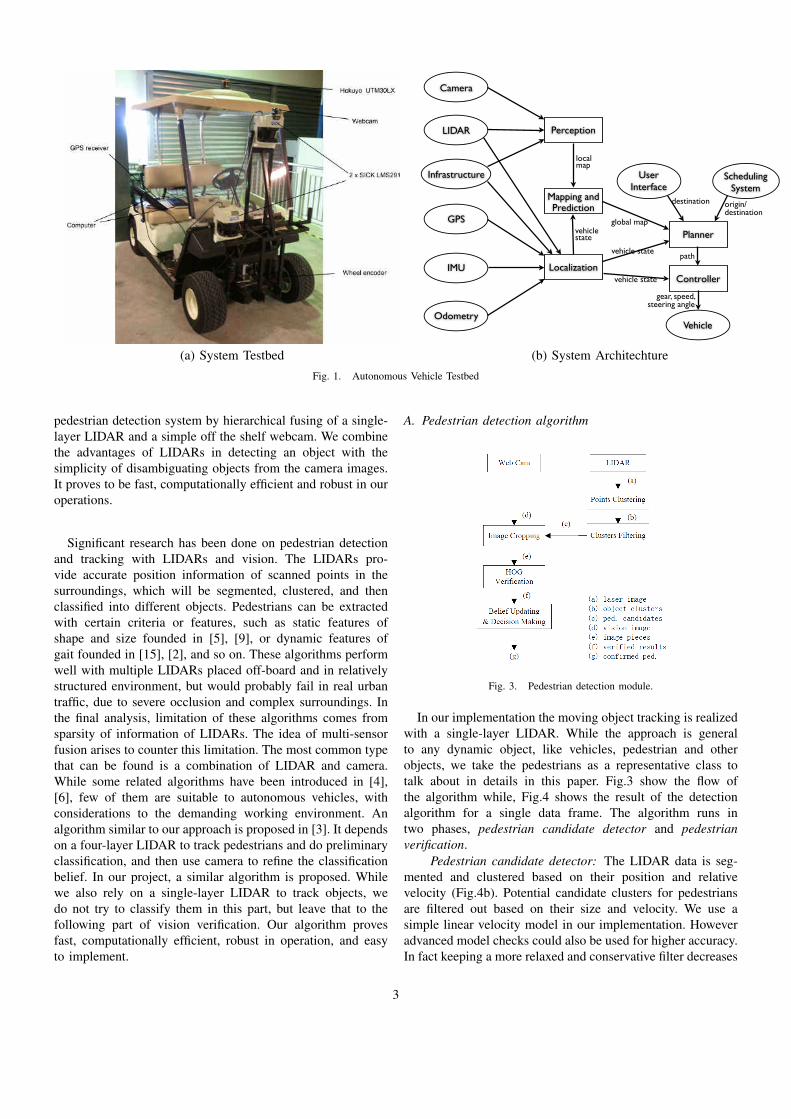
Our autonomous vehicle testbed is a Yamaha G22E golf carmounted with various sensors (Fig.1a). It was modified andequipped with actuators to achieve drive by wire capabilities.Two servo motors are used to control the steering angle andamount of brake applied separately. Since it is an electricvehicle, the throttle control is readily accessible through avarying PWM voltage signal that can be regulated by alow level controller. To fulfill the power requirement for awide variety of sensors, a 1350W inverter was used. For thesensors, a wheel encoder is fitted at the left front wheel.The steering angle and brake are inferred implicitly from themotors encoder. To receive GPS signal, Ublox EVK-6R isused. The module comes with Enhanced Kalman Filter to givean estimate of global location using integrated data input fromwheel encoders tick count and onboard gyroscope. The mainsensors are the laser range finders that consist of two SICKLMS 291 and Hokuyo UTM 30LX. The SICK lasers have arange of 80 m with 180◦ field-of-view (FoV). The Hokuyosensor, on the other hand, has 270◦ FoV with 30 m range. Anormal webcam is fitted on one of the SICK lasers to providevisual feedback and to perform vision processing.
Software Architecture: We have developed a modularsoftware architecture for ease in incorporating additionalfunctionality without modifying the core system. The systemhas been integrated into ROS (Robotic Operating System),which provides a standard form of communication amongdifferent software modules [11]. The main modules that havebeen implemented on the current system include perception,mapping-and-prediction, localization, planner and controller asshown in Fig. 1b.
The perception module takes as an input the raw senseddata from the sensors. Detection and tracking algorithm is thenapplied to extracted features (e.g., pedestrian and other moving
and stationary objects) from the raw sensed data. As discussedin Section V, the sensors we have utilized include not onlyonboard cameras and laser range finders but also infrastructurecameras installed, for example, at an intersection. The datafrom these infrastructure cameras are transmitted through aWiFi network. To reduce the amount of data that needs tobe transmitted, the raw sensed data may be processed so thatonly important features (e.g., other vehicles and pedestriansapproaching the intersection) are transmitted.
The mapping-and-prediction module maintains the globalmap of the environment in which the system is operating.In addition, it predicts the motion of moving objects suchas pedestrians. The localization module incorporates the datareceived from the GPS (Global Positioning System), IMU(Inertial Measurement Unit), laser range finder and vehicle’sodometer to provide an estimate of the current state (position,velocity and heading) of the vehicle.
The planner module is responsible for computing anobstacle-free path, satisfying certain traffic rules, to the goal. Inthe case where the user is onboard, the goal may be specifiedas the destination through the user interface. Alternatively,the scheduling system that computes the pick-up and drop-offposition for each autonomous vehicle may send the origin anddestination to the system through a cellular network. Finally,the controller module is responsible for computing the actuatorcommands, including the speed, gear and steering angle, tothe physical actuators so that the vehicle closely follows theplanner-generated path.
III. PEDESTRIAN DETECTION
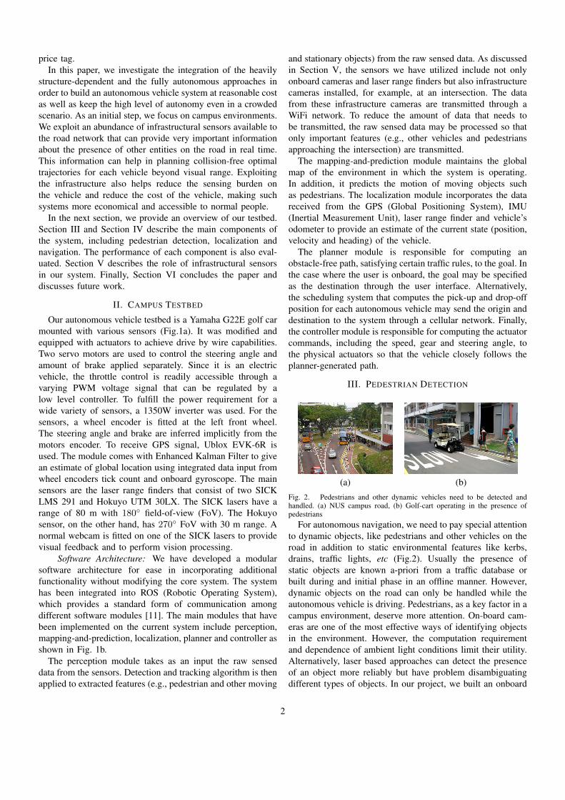
(a) (b)Fig. 2. Pedestrians and other dynamic vehicles need to be detected andhandled. (a) NUS campus road, (b) Golf-cart operating in the presence ofpedestrians
For autonomous navigation, we need to pay special attentionto dynamic objects, like pedestrians and other vehicles on theroad in addition to static environmental features like kerbs,drains, traffic lights, etc (Fig.2). Usually the presence ofstatic objects are known a-priori from a traffic database orbuilt during and initial phase in an offline manner. However,dynamic objects on the road can only be handled while theautonomous vehicle is driving. Pedestrians, as a key factor in acampus environment, deserve more attention. On-board cam-eras are one of the most effective ways of identifying objectsin the environment. However, the computation requirementand dependence of ambient light conditions limit their utility.Alternatively, laser based approaches can detect the presenceof an object more reliably but have problem disambiguatingdifferent types of objects. In our project, we built an onboard
2
Localization
Perception
Mapping and Prediction
Planner
Controller
gear, speed, steering angle
path
Camera
LIDAR
Infrastructure
GPS
IMU
Odometry
User Interface
Scheduling System
destination origin/destination
vehicle state
global map
vehicle state
vehicle state
local map
Vehicle
(a) System Testbed (b) System ArchitechtureFig. 1. Autonomous Vehicle Testbed
pedestrian detection system by hierarchical fusing of a single-layer LIDAR and a simple off the shelf webcam. We combinethe advantages of LIDARs in detecting an object with thesimplicity of disambiguating objects from the camera images.It proves to be fast, computationally efficient and robust in ouroperations.
Significant research has been done on pedestrian detectionand tracking with LIDARs and vision. The LIDARs pro-vide accurate position information of scanned points in thesurroundings, which will be segmented, clustered, and thenclassified into different objects. Pedestrians can be extractedwith certain criteria or features, such as static features ofshape and size founded in [5], [9], or dynamic features ofgait founded in [15], [2], and so on. These algorithms performwell with multiple LIDARs placed off-board and in relativelystructured environment, but would probably fail in real urbantraffic, due to severe occlusion and complex surroundings. Inthe final analysis, limitation of these algorithms comes fromsparsity of information of LIDARs. The idea of multi-sensorfusion arises to counter this limitation. The most common typethat can be found is a combination of LIDAR and camera.While some related algorithms have been introduced in [4],[6], few of them are suitable to autonomous vehicles, withconsiderations to the demanding working environment. Analgorithm similar to our approach is proposed in [3]. It dependson a four-layer LIDAR to track pedestrians and do preliminaryclassification, and then use camera to refine the classificationbelief. In our project, a similar algorithm is proposed. Whilewe also rely on a single-layer LIDAR to track objects, wedo not try to classify them in this part, but leave that to thefollowing part of vision verification. Our algorithm provesfast, computationally efficient, robust in operation, and easyto implement.
A. Pedestrian detection algorithm
Fig. 3. Pedestrian detection module.
In our implementation the moving object tracking is realizedwith a single-layer LIDAR. While the approach is generalto any dynamic object, like vehicles, pedestrian and otherobjects, we take the pedestrians as a representative class totalk about in details in this paper. Fig.3 show the flow ofthe algorithm while, Fig.4 shows the result of the detectionalgorithm for a single data frame. The algorithm runs intwo phases, pedestrian candidate detector and pedestrianverification.
Pedestrian candidate detector: The LIDAR data is seg-mented and clustered based on their position and relativevelocity (Fig.4b). Potential candidate clusters for pedestriansare filtered out based on their size and velocity. We use asimple linear velocity model in our implementation. Howeveradvanced model checks could also be used for higher accuracy.In fact keeping a more relaxed and conservative filter decreases
3
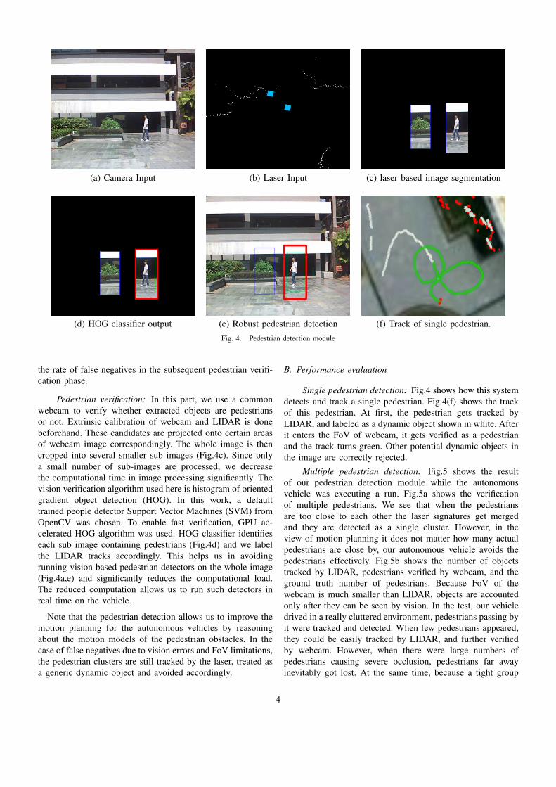
(a) Camera Input (b) Laser Input (c) laser based image segmentation
(d) HOG classifier output (e) Robust pedestrian detection (f) Track of single pedestrian.Fig. 4. Pedestrian detection module
the rate of false negatives in the subsequent pedestrian verifi-cation phase.
Pedestrian verification: In this part, we use a commonwebcam to verify whether extracted objects are pedestriansor not. Extrinsic calibration of webcam and LIDAR is donebeforehand. These candidates are projected onto certain areasof webcam image correspondingly. The whole image is thencropped into several smaller sub images (Fig.4c). Since onlya small number of sub-images are processed, we decreasethe computational time in image processing significantly. Thevision verification algorithm used here is histogram of orientedgradient object detection (HOG). In this work, a defaulttrained people detector Support Vector Machines (SVM) fromOpenCV was chosen. To enable fast verification, GPU ac-celerated HOG algorithm was used. HOG classifier identifieseach sub image containing pedestrians (Fig.4d) and we labelthe LIDAR tracks accordingly. This helps us in avoidingrunning vision based pedestrian detectors on the whole image(Fig.4a,e) and significantly reduces the computational load.The reduced computation allows us to run such detectors inreal time on the vehicle.
Note that the pedestrian detection allows us to improve themotion planning for the autonomous vehicles by reasoningabout the motion models of the pedestrian obstacles. In thecase of false negatives due to vision errors and FoV limitations,the pedestrian clusters are still tracked by the laser, treated asa generic dynamic object and avoided accordingly.
B. Performance evaluation
Single pedestrian detection: Fig.4 shows how this systemdetects and track a single pedestrian. Fig.4(f) shows the trackof this pedestrian. At first, the pedestrian gets tracked byLIDAR, and labeled as a dynamic object shown in white. Afterit enters the FoV of webcam, it gets verified as a pedestrianand the track turns green. Other potential dynamic objects inthe image are correctly rejected.
Multiple pedestrian detection: Fig.5 shows the resultof our pedestrian detection module while the autonomousvehicle was executing a run. Fig.5a shows the verificationof multiple pedestrians. We see that when the pedestriansare too close to each other the laser signatures get mergedand they are detected as a single cluster. However, in theview of motion planning it does not matter how many actualpedestrians are close by, our autonomous vehicle avoids thepedestrians effectively. Fig.5b shows the number of objectstracked by LIDAR, pedestrians verified by webcam, and theground truth number of pedestrians. Because FoV of thewebcam is much smaller than LIDAR, objects are accountedonly after they can be seen by vision. In the test, our vehicledrived in a really cluttered environment, pedestrians passing byit were tracked and detected. When few pedestrians appeared,they could be easily tracked by LIDAR, and further verifiedby webcam. However, when there were large numbers ofpedestrians causing severe occlusion, pedestrians far awayinevitably got lost. At the same time, because a tight group
4

0 200 400 600 800 1000 1200 1400 1600 1800 20000
1
2
3
4
5
6
7
8
Time Step
Pede
stria
n D
etec
tion
Laser Detection
Vision Verified
Manual Detection
(a) Snapshot of the onboard pedestrian detector (b) Pedestrian detection reliability during the autonomous runFig. 5. Pedestrian detection from an autonomous run of our testbed.
of pedestrians were counted as one, sometimes the numberof verified pedestrians appeared to be fewer than the groundtruth. In the test, most pedestrians got detected, whether as anindividual, or as a group, making safe autonomous driving ofour vehicle. Frequency of this detection system is up to 37Hz,limited by scan frequency from LIDAR. Range of effectivedetection is about 15 meters, limited by resolution of webcam.
Through experiments in different conditions, our onboardpedestrian detection system proves to be both efficient andreliable, and at same time, easily tractable. But due to limitedFoV and poor resolution of common webcam, pedestrianswalking aside or too far away cannot be verified. At the sametime, because we take group of pedestrians as a single one,we cannot get the exact number of pedestrians.
IV. LOCALIZATION AND AUTONOMOUS NAVIGATION
Most of the popular approaches in autonomous navigationoutdoors depend heavily on GPS based localization. In factthe DARPA challenge was based on GPS based waypointsas input. However GPS is not very reliable in urban areasdue to multi-path, limited satellite view in tall sky-scrapers.Such a scenario is shown in Fig.6a. A cloudy sky coupledwith tall buildings can attenuate the GPS signals, resulting inerroneous localization as shown by the GPS track in Fig.6b. Asthe vehicle moves, its GPS erroneously estimates the vehiclelocation inside buildings and a pure GPS based localizationand control could lead to failed navigation.
Interestingly one of the main reasons of GPS limitation i.e,the proximity of buildings, itself provides a good opportunityto utilize range based localization algorithms. In our work weuse the laser based maps to augment in regions where GPSunderperforms.
A. Localization
We evaluated several localization approaches on our au-tonomous vehicle testbed in the campus environment. Whilethe integrated GPS + Gyroscope localizes the vehicle ina global manner, as shown above (Fig.6b), it gives quitepoor position estimate. Another approach we looked intowas using the LIDAR corrected dead reckoning. Odometry
(a) (b)Fig. 6. Bad GPS with integrated gyro based odometry
information derived from wheel encoder was able to give anaccurate estimation about the distance travel by the vehicle.To obtain the vehicle heading, scan matcher technique wasused by comparing the laser scan return. By combining these2 estimates, we obtained a well-established estimate of thevehicle state. For an autonomous vehicle operating in an urbanor campus environment, it is reasonable to assume that a-priori maps could be generated to aid online navigation. Withthe availability of a-priori laser map, Adaptive Monte CarloLocalization (AMCL) [12] technique was also evaluated. Aprior map was built by using the laser thats mounted at a heightof 1.83 m. The height of the laser was chosen such that morestable features can be collected and thus increase the belief ofthe position of the vehicle even in a dynamic environment. Tobuild the map, the vehicle was driven around the environmentat a slow speed. While the vehicle was going around, rawlaser data and odometry information collected. Generation ofmap was done offline using SLAM technique that is availablefrom OpenSLAM [1]. Similar to map building, informationfrom odometry and raw laser data was used as input data toprovide the most recent observation about the environmentand perform calculation on the most probable location of the
5

vehicle.
(a) Laser map used for Localization
(b) Results of various localization algorithms
Fig. 7. Comparison of various localization schemes
Laser based corrections significantly improve on the pureGPS based localization. We show the results of an autonomousrun in Fig.7. Fig.7b shows the localization results of variousalgorithms running on the same run. The red track shows theGPS logs while the blue track shows the location of the vehicleusing the odometry alone. The green track is computed bythe AMCL algorithm. This shows that in areas of poor GPSlocations, building a-priori occupancy maps and subsequentlylocalizing using approaches like AMCL significantly improvethe operation. For all our runs, we have used the AMCLalgorithm which has shown to work robustly even in thepresence of temporary spatial occlusions due to other dynamicvehicles.
B. Cost based Navigation function
Fig. 8. Navigation module of the autonomous vehicle
Fig.8 shows the structure of our navigation module. Duringeach run, the vehicle maintains its own map based on rollingbasis, with the vehicle centered on the map. A map of 50mx 50m with a grid cell size of 0.2m is maintained at all time.Each cell in the map can have a 1 byte value. Initially, thecells in the map are marked as unknown with a value of 255.Whenever an obstacle is observed, the map is updated witha cost value of 254, with the cells now marked as obstacles,the cost is propagated radially outward with an exponentialfunction. At the low level, speed and steering control areseparated. For the speed control, the vehicle considers the
following input before planning for next action: the averagecost function that is present within a defined area in frontof itself and the curvature of the path. To ensure stability, aconservative approach is utilized. First, an exponential functionis used to calculate the safe speed given the steering angle ofthe golf car. Then, from the normalized average cost along theprojection of the golf car within a fix distance, another safespeed is obtained. Between these 2 values, the minimum one ischosen as the final set point for the speed. The implementationof waypoint follower uses pure pursuit control [7]. Since thegolf car’s maximum speed is limited to 2 m/s, the look-aheadvector is fixed to 3 meters.
V. EXPLOITING INFRASTRUCTURE SENSORS
An important feature that distinguishes urban environmentsfrom those considered in military applications is the tech-nological advances that we can exploit in order to increasesafety and efficiency of the system without imposing muchadditional cost. Consider, as an example, the scenario wherean autonomous vehicle has to traverse an intersection. In manycases, other vehicles approaching the intersection from otherdirections may not be detected properly by the onboard sensorsdue to limited sensing coverage and occlusions caused bystructures and other environmental features. In [13], the au-thors mitigate this problem by using two pointable long-rangesensors and propose a methodology for computing the optimalangles of the sensors to maximally cover relevant unobservedregions of interest. A method for detecting occlusions is alsopresented. A phantom vehicle is then placed in the occludedarea, leading to a safe but potentially conservative result.
In this work, we consider utilizing infrastructure cameras in-stalled, for example, at an intersection, rather than completelyrelying on the onboard sensors. These infrastructure camerascan provide information about whether there are pedestrians orother vehicles approaching the intersection. The informationcan then be transmitted through a WiFi or cellular network. Anadvantage of this approach is that more accurate informationcan be obtained as the infrastructure cameras may be mountedto avoid occlusions. In addition, as the number of autonomousvehicles in the system exceed the number of intersections, thecost can be substantially reduced. In fact, in many moderncities, cameras are already installed at many intersections todetect traffic violations. Hence, this approach may incur almostno additional cost.
A. Avoiding Unobservable Pedestrians
To show the effect of additional information, we simulatean infrastructural sensor as a wifi-node broadcasting specificinformation. The infrastructural camera detects the presenceof pedestrians and gives a binary information to the golf-cartwhether there are pedestrians about to cross the road or if theregion is pedestrian free. Currently we are not building modelsof pedestrian intentions to analyze whether the pedestrian isfacing the road or whether s/he is just waiting rather thantrying to cross the road. Any pedestrian detection wouldtrigger the autonomous vehicle to slow down in anticipationfor the pedestrian to cross the road. The rate of pedestrian
6

detection is 5 Hz. However, since the algorithm only dependson the pedestrian detection alone and not a more detailedanalysis based on the pedestrian position and heading, it wouldalso work well with modern traffic/security cameras operatingaround 1Hz.
Fig.9(a,b) show the view of the scene from onboard as wellas a mock infrastructure sensor. The detection of the pedestrianin the left of the image in Fig.9a is quite difficult due to theocclusion from pillars and railings. The autonomous vehiclehas to communicate with an existing sensor (security camera)to get more information to plan its path. The pedestrian de-tection is much easier in Fig.9b. The autonomous vehicle getsthe pedestrian information from the infrastructure pedestriandetector sensor and modifies its motion plan, as shown inFig.9c. We see that during the detection of pedestrians, theautonomous vehicle checks for the possibility of collisionand slows down if there is high chance of collision with thepedestrian. The videos of the operation can be accessed athttp://dl.dropbox.com/u/20792983/pedestrianVisual1.mp4 andhttp://dl.dropbox.com/u/20792983/pedestrianVisual2.mp4.
Fig. 10. Velocity profile with pedestrian detection
. . .
Ped. Sensor
V2 V1
Ped. sensing region
Ped. crossing
Looped track
Fig. 11. Simulation environment setup.
1) Control comparative experiments: Clearly, we would seean improvement in the navigation performance while incor-porating the information from an infrastructural sensor. Werun a control experiment in simulation to compare quantitative
improvement. Our simulator setup is shown as in Fig.11. Oneor more vehicles move in a loop that has a pedestrian crossing.A pedestrian detection sensor (i.e., a traffic camera) detectsthe presence of pedestrians and sends information to theautonomous vehicles V 1, V 2, . . .. Depending on the presenceof pedestrians, the vehicles slow down or keep moving. Thevehicles are also constrained to maintain a minimum distancebetween them to avoid collision. We run the experiment bothfor a single vehicle as well as multiple vehicles. We comparethe performance with the baseline case where there is noinfrastructural sensors and the autonomous vehicle has to cometo a stop before detecting pedestrians on road, somethingsimilar to a regular stop and yeild traffic sign. We run thesimulation for various vehicle speeds and various number ofvehicles. Let Tbase be the time taken to reach the pedestriancrossing by the baseline algorithm, while Tinfra. be the samemeasure for our algorithm getting additional information fromthe infrastructure sensor. We compute the difference in thetime taken to complete each lap, as the time gained by usingthe infrastructural sensor, Tgain = Tbase − Tinfra.. In bothcases the pedestrians appear in a stochastic manner using apoisson process of mean rate of λ = 1ped/sec.
Single Vehicle: Fig.12a, shows the plot of Tgain vs thenumber of laps the vehicle completes. We see clearly thatthe cumulative time gained by using the infrastructural sensorimproves with time. We also note that such a gain is moresignificant when the vehicle moves at a higher speed. Theblue plot is the gain for vehicle moving at 2m/s while the redat 1m/s. This shows that the traffic flow at pedestrian crossingswhere the vehicles are able to move at higher speeds can besignificantly improved by using infrastructural sensors.
Multiple Vehicles: Fig.12b, shows the plot of Tgain vsthe number of laps the vehicle completes for multiple vehicles.We see that as the number of vehicles increases, Tgain alsoincreases. This is because in the baseline algorithm, eachvehicle has to stop for pedestrians whether or not they arepresent. Additionally they have to stop to maintain a minimumdistance to the vehicle in front when the front vehicle stops.The number of vehicle stops increase significantly when thenumber of vehicles increases raising the discrepancy betweenthe proposed and the baseline algorithm.
VI. CONCLUSION AND FUTURE DIRECTIONS
We considered three main challenges in autonomous naviga-tion in crowded city environments: localization, pedestrian de-tection and limited onboard sensing capability. We showed thatin the proximity of tall buildings, popular GPS-based localiza-tion can be extremely erroneous. Odometry-based localizationwas shown to perform slightly better. In order to achieveacceptable performance, we augmented the localization usinglocal laser maps based on Adaptive Monte Carlo Localizationtechnique and showed significantly improved results. We alsointegrated the use of vision and LIDARs to achieve morerobustness in pedestrian detection and tracking. Finally, weexploited existing infrastructural sensors to improve the on-board sensors visibility. The performance of the overall system
7

(a) Onboard camera view (b) Infrastructure camera view (c) Vehicle in operationFig. 9. Pedestrian crossing experiment
0 10 20 30 40 50−20
0
20
40
60
80
Time step
Tga
in
Vel 1m/s
Vel 2m/s
0 10 20 30 40 50−20
0
20
40
60
80
Time step
Tgai
n
Vehicle 1
Vehicle 2
Vehicle 3
(a) Single vehicle (b) Multiple vehiclesFig. 12. Improvement in traffic flow due to incorporating infrastructural sensing
was evaluated.Future work targets at augmenting the current system to
a fully automated campus vehicle system. To this end, weare currently investigating the use of WiFi-based localiza-tion as a complementary approach to GPS-based and laser-based localization. We also plan to incorporate pedestrianintentions in motion planning. Implementation of high-levellogics to ensure that the autonomous vehicle obeys trafficrules, properly handles pedestrian and responds to faults andfailures is also of interest. In addition, we intend to incorporateadditional infrastructure devices such as dedicated short rangecommunication beacons that will be used in ERP Phase 2 inSingapore. We will also take advantage of sensors that maybe on other vehicles and exploit communications possibilities.Finally, the system needs to be verified for safety both fornominal operations and in the presence of faults and failures.
REFERENCES
[1] OpenSLAM. http://openslam.org/.[2] J. Cui, H. Zha, H. Zhao, and R. Shibasaki, “Robust tracking of multiple
people in crowds using laser range scanners,” in Proceedings of ICPR,vol. 4, 2006, p. 857.
[3] F. N. G. Gate, A. Breheret, “Fast pedestrian detection in dense envi-ronment with a laser scanner and a camera,” in Proceedings of IEEEVehicular Technology Conference, 2009.
[4] R. S. H. Zhao, “A real-time system for monitoring pedestrians,” inProceedings of IEEE WACV/Motions, vol. 1, 2005, p. 378.
[5] V. W. K. Fuerstenberg, K. Dietmayer, “Pedestrian recognition in urbantraffic using a vehicle based multilayer laserscanner,” in Proceedings ofIntelligent Vehicle Symposium, 2002.
[6] Y. Kobayashi and Y. Kuno, “People tracking using integrated sensors forhuman robot interaction,” in Proceedings of 2010 IEEE InternationalConference on Industrial Technology, 2010, p. 1617.
[7] Y. Kuwata, J. Teo, G. Fiore, S. Karaman, E. Frazzoli, and J. P.How. Real-time motion planning with applications to autonomous urbandriving. http://dspace.mit.edu/openaccess-disseminate/1721.1/52527.
[8] J. Markoff, “Google cars drive themselves, in traffic,” The New YorkTimes, October 9, 2010.
[9] T. H. O. Mozos, R. Kurazume, “Multi-part people detection using 2drange data,” in Proceedings of 2009 IEEE ICRA, 2009.
[10] M. Pavone, K. Treleaven, and E. Frazzoli, “Fundamental performancelimits and efficient polices for transportation-on-demand systems,” inIEEE Conf. on Decision and Control, 2010.
[11] M. Quigley, K. Conley, B. P. Gerkey, J. Faust, T. Foote, J. Leibs,R. Wheeler, and A. Y. Ng, “ROS: an open-source Robot OperatingSystem,” in ICRA Workshop on Open Source Software, 2009.
[12] D. F. Sebastian Thrun, Wolfram Burgard, Probabilistic Robotics. MIT.Press, 2005.
[13] Y.-W. Seo and C. Urmson, “A perception mechanism for supportingautonomous intersection handling in urban driving,” in IEEE/RSJ Inter-national Conference on Intelligent Robots and Systems (IROS), 2008,pp. 1830–1835.
[14] S. E. Shladover, “Potential contributions of intelligent vehicle/highwaysystems (IVHS) to reducing transportation’s greenhouse gas production,”Transportation Research Part A: Policy and Practice, vol. 27, no. 3, pp.207 – 216, 1993.
[15] H. Zhao and R. Shibasaki, “A novel system for tracking pedestriansusing multiple single-row laser-range scanners,” in Proceedings of 2005IEEE Transactions on Systems, Man, and Cybernetics-Part A: Systemsand Humans, vol. 35, no. 2, March 2005.
8