automotive component failures -...
TRANSCRIPT
En`ineerin` Failure Analysis\ Vol[ 4\ No[ 1\ pp[ 018Ð030\ 0887Þ 0887 Elsevier Science Ltd[ All rights reserved\ Pergamon Printed in Great Britain
0249Ð5296:87 ,08[99 ¦ 9[99
PII] S0249Ð5296"87#99909Ð6
AUTOMOTIVE COMPONENT FAILURES
A[ M[ HEYES
Advanced Engineering and Testing Services\ CSIR\ Private Bag X17\ Auckland Park 1995\Republic of South Africa[
"Received 2 February 0887#
Abstract*The failure of vehicle components is an area which is likely to a}ect all of us at one stage or another[In this paper the distribution of component failures is discussed\ as well as the causes thereof[ Four case studiesare presented to give insight in the methodology of failure analysis of automotive components\ and the valuableinformation which can be gained thereby[ Þ 0887 Elsevier Science Ltd[ All rights reserved[
Keywords] Accident investigation\ automotive failures\ decarburization\ fatigue\ weld fatigue[
0[ INTRODUCTION
Failure of automotive components is an occurrence which a}ects the life of almost every person atone stage or another[ Components in a vehicle often operate under arduous conditions and in manycases are required to last the lifetime of the vehicle without any form of inspection[ Often\ the failureof a component results in no more than a nuisance with replacement of that part being required[However\ failure of some components can result in loss of control of the vehicle\ with the obviouspossibility of accidents and loss of life[ Such parts are known as safety critical items and a batchrelated in!service failure of such parts will often result in the recall of all a}ected vehicles with theassociated cost and bad publicity[ Thus\ it is often the case in automotive failure analysis that it isimperative to determine whether the failure is an isolated case or is likely to occur in more vehicles[
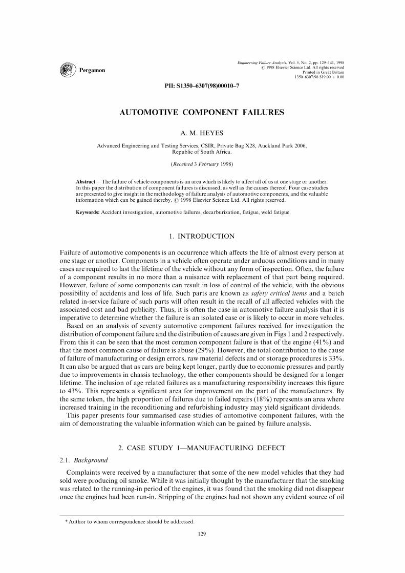
Based on an analysis of seventy automotive component failures received for investigation thedistribution of component failure and the distribution of causes are given in Figs 0 and 1 respectively[From this it can be seen that the most common component failure is that of the engine "30)# andthat the most common cause of failure is abuse "18)#[ However\ the total contribution to the causeof failure of manufacturing or design errors\ raw material defects and or storage procedures is 22)[It can also be argued that as cars are being kept longer\ partly due to economic pressures and partlydue to improvements in chassis technology\ the other components should be designed for a longerlifetime[ The inclusion of age related failures as a manufacturing responsibility increases this _gureto 32)[ This represents a signi_cant area for improvement on the part of the manufacturers[ Bythe same token\ the high proportion of failures due to failed repairs "07)# represents an area whereincreased training in the reconditioning and refurbishing industry may yield signi_cant dividends[
This paper presents four summarised case studies of automotive component failures\ with theaim of demonstrating the valuable information which can be gained by failure analysis[
1[ CASE STUDY 0*MANUFACTURING DEFECT
1[0[ Back`round
Complaints were received by a manufacturer that some of the new model vehicles that they hadsold were producing oil smoke[ While it was initially thought by the manufacturer that the smokingwas related to the running!in period of the engines\ it was found that the smoking did not disappearonce the engines had been run!in[ Stripping of the engines had not shown any evident source of oil
� Author to whom correspondence should be addressed[
018
029 A[ M[ HEYES
Fig[ 0[ The distribution of component failures[
Fig[ 1[ The distribution of causes of failure[
ingress[ An engine which had been removed from a vehicle due to smoking was supplied forinvestigation[ The engine had been in service for approximately 19\999 km[
1[1[ Visual examination
Upon stripping the engine it was found that one of the combustion chambers showed heavycarbonaceous deposits indicative of the burning of oil "Fig[ 2# Circumferential black marks werefound at di}ering heights in the bores of three of the cylinders[ The visible honing pattern wasdeemed to be satisfactory[ No source of oil ingress was evident at this stage[
1[2[ Dimensional measurements
Measurements of the ovality and taper of the bores and the ring gaps all gave good results[This\ together with the satisfactory honing pattern\ made leakage of oil past the rings unlikely[

020Automotive component failures
Fig[ 2[ Carbonaceous deposits left in combustion chamber by burnt oil[
Measurement of the ~atness of the sealing face of the aluminium head and the deck of the blockshowed only negligible "9[94 mm# deviation from ~atness and\ as the head gasket showed no signsof leakage\ ingress of oil via the head to block seal was ruled out[
1[3[ Ma`netic particle inspection "MPI#
The circumferential mark in the a}ected cylinder was indicated by MPI as being a crack likedefect[ However\ upon sectioning the cylinder bore it was found that the marks were\ in fact\ shallowcorrosion and fretting marks left where the chromium plated piston rings contacted the cylinderwall[ The presence of these marks is explained by the fact that the engines are imported and are testrun before shipping\ quite possibly leaving combustion condensate in the cylinder[ It was possibleto eliminate these as a cause of oil ingress as they did not penetrate the cylinder wall and were notdeep enough to retain signi_cant amounts of oil[
1[4[ Fluorescent dye penetrant inspection and leak testin` of cylinder head
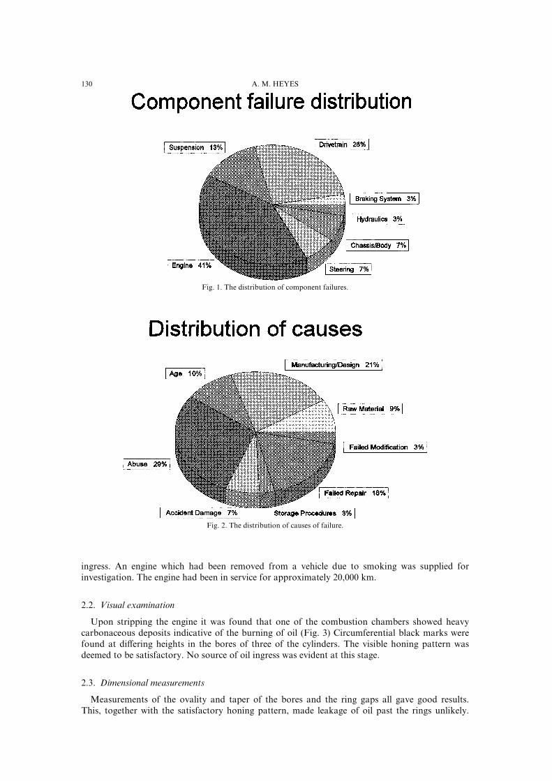
Due to the non!magnetic nature of the cylinder head ~uorescent dye penetrant testing was carriedout but failed to show any signi_cant defects in the head[ An alternate testing procedure involvingpressurisation of the inlet ports and immersion of the head in a water bath showed the source of oilingress to be a crack in the head where the valve guide had been inserted "Fig[ 3#[ Fluorescent dyepenetrant testing had failed to show the defect as it had been hidden under a steel spring seat[
1[5[ Conclusions
This crack led through to the inlet port of the a}ected cylinder and the engine would draw oilinto the engine on every intake stroke[ Inspection of the inlet ports of other a}ected enginesshowed the same defect[ The cause of the defect was related to manufacturing tolerances where theinterference _t of the valve guide and the head was too tight\ resulting in cracking of the headadjacent to the guide[
2[ CASE STUDY 1*RAW MATERIAL DEFECT IN TORSION BAR
2[0[ Back`round
Torsion bars are used in the suspension of some vehicles\ either to replace conventional springsor to form part of anti!sway system[ As the handling of a vehicle is drastically a}ected by a failurein either role\ torsion bars fall into the category of safety critical items\ as discussed in Section 0[
021 A[ M[ HEYES
Fig[ 3[ The crack in the cylinder head caused by insertion of the valve guide[
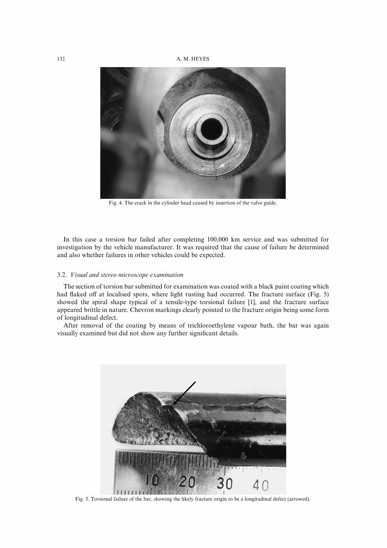
In this case a torsion bar failed after completing 099\999 km service and was submitted forinvestigation by the vehicle manufacturer[ It was required that the cause of failure be determinedand also whether failures in other vehicles could be expected[
2[1[ Visual and stereo microscope examination
The section of torsion bar submitted for examination was coated with a black paint coating whichhad ~aked o} at localised spots\ where light rusting had occurred[ The fracture surface "Fig[ 4#showed the spiral shape typical of a tensile!type torsional failure ð0Ł\ and the fracture surfaceappeared brittle in nature[ Chevron markings clearly pointed to the fracture origin being some formof longitudinal defect[
After removal of the coating by means of trichloroethylene vapour bath\ the bar was againvisually examined but did not show any further signi_cant details[
Fig[ 4[ Torsional failure of the bar\ showing the likely fracture origin to be a longitudinal defect "arrowed#[

022Automotive component failures
Fig[ 5[ Seam defect in torsion bar highlighted by ~uorescent MPI[
2[2[ Fluorescent ma`netic particle inspection
Fluorescent magnetic particle inspection showed that a seam or lap defect existed for a further199 mm from the fracture site "Fig[ 5#[ Such defects are usually laps formed by incorrect rollingprocedures or are seams attributable to steel defects "inclusions#[ Two further seams were found\but were of a very small size[
2[3[ Chemical analysis
The bar was found to be a chromium steel meeting the compositional requirements of an AISI4049 steel "9[42) C\ 9[71) Mn\ 9[70) Cr#[ This composition would indicate a high hardenabilitysteel[
2[4[ Hardness testin`
Hardness tests gave a hardness of 497 HV29 which equates to an ultimate tensile strength ofapproximately 0639 MPa ð1Ł[ Such high tensile strengths are required to prevent yielding or fatigueof the bar during operation[ A disadvantage of steels which rely on non!toughening strengtheningadditions such as carbon\ manganese and chromium is that strength and toughness are inverselyrelated\ i[e[ high strength levels result in low toughness[
2[5[ Scannin` Electron Microscope "SEM# fracto`raphic examination
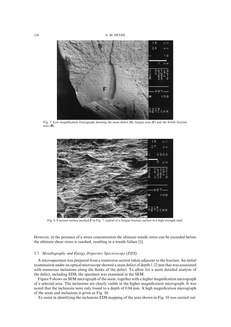
The fracture surface was sectioned from the remainder of the bar and was examined in the SEM[Figure 6 clearly shows how a penny shaped fatigue crack had grown from the seam defect[ Whenthe crack had grown to a size of approximately 2[4 mm the bar was unable to tolerate a defect ofthis size and underwent fast fracture[ This relatively small defect tolerance is related to the lowtoughness\ as described above[ Figure 7 shows the appearance of the area of fatigue crack at 1999times magni_cation[ The morphology of the surface is typical of a steel fatigue fracture surface[Higher magni_cation examination of the fracture surface failed to show individual striations\ thisbeing usual for high strength steels[
The presence of a stress concentrating factor such as a crack can often change the torsionalfracture mode from one of shear to tensile fracture "as in this case#[ This is due to the relationshipbetween ultimate shear stress and ultimate tensile stress[ In the case of steels where the ultimateshear stress is approximately half of the ultimate tensile stress\ a shear failure would be expected[
023 A[ M[ HEYES
Fig[ 6[ Low magni_cation fractograph showing the seam defect "S#\ fatigue area "F# and the brittle fracturearea "B#[
Fig[ 7[ Fracture surface marked F in Fig[ 6\ typical of a fatigue fracture surface in a high strength steel[
However\ in the presence of a stress concentration the ultimate tensile stress can be exceeded beforethe ultimate shear stress is reached\ resulting in a tensile failure ð0Ł[
2[6[ Metallo`raphy and Ener`y Dispersive Spectroscopy "EDS#
A microspecimen was prepared from a transverse section taken adjacent to the fracture[ An initialexamination under an optical microscope showed a seam defect of depth 0[11 mm that was associatedwith numerous inclusions along the ~anks of the defect[ To allow for a more detailed analysis ofthe defect\ including EDS\ the specimen was examined in the SEM[
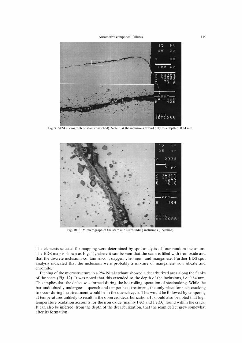
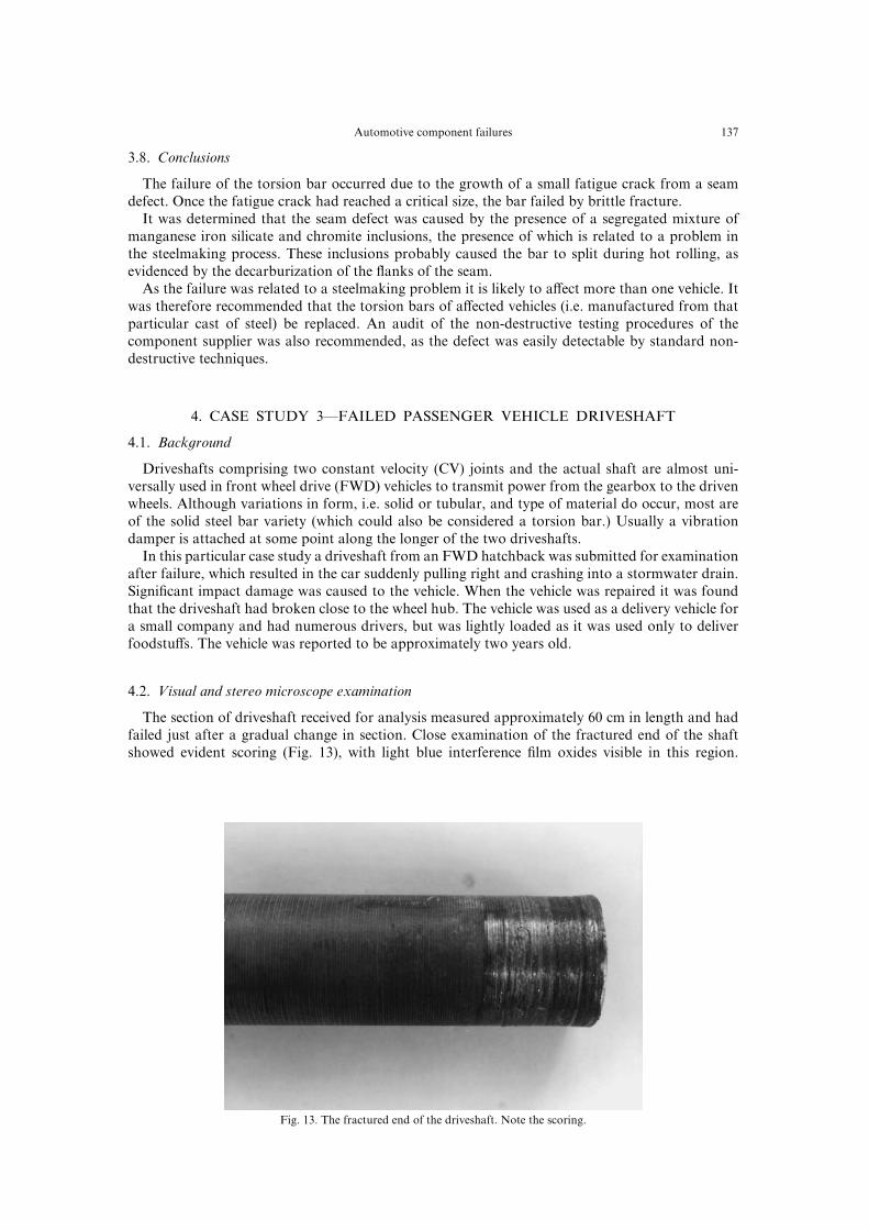
Figure 8 shows an SEM micrograph of the seam\ together with a higher magni_cation micrographof a selected area[ The inclusions are clearly visible in the higher magni_cation micrograph[ It wasnoted that the inclusions were only found to a depth of 9[73 mm[ A high magni_cation micrographof the seam and inclusions is given as Fig[ 09[
To assist in identifying the inclusions EDS mapping of the area shown in Fig[ 09 was carried out[
024Automotive component failures
Fig[ 8[ SEM micrograph of seam "unetched#[ Note that the inclusions extend only to a depth of 9[73 mm[
Fig[ 09[ SEM micrograph of the seam and surrounding inclusions "unetched#[
The elements selected for mapping were determined by spot analysis of four random inclusions[The EDS map is shown as Fig[ 00\ where it can be seen that the seam is _lled with iron oxide andthat the discrete inclusions contain silicon\ oxygen\ chromium and manganese[ Further EDS spotanalysis indicated that the inclusions were probably a mixture of manganese iron silicate andchromite[
Etching of the microstructure in a 1) Nital etchant showed a decarburized area along the ~anksof the seam "Fig[ 01#[ It was noted that this extended to the depth of the inclusions\ i[e[ 9[73 mm[This implies that the defect was formed during the hot rolling operation of steelmaking[ While thebar undoubtedly undergoes a quench and temper heat treatment\ the only place for such crackingto occur during heat treatment would be in the quench cycle[ This would be followed by temperingat temperatures unlikely to result in the observed decarburization[ It should also be noted that hightemperature oxidation accounts for the iron oxide "mainly FeO and Fe2O3# found within the crack[It can also be inferred\ from the depth of the decarburization\ that the seam defect grew somewhatafter its formation[

025 A[ M[ HEYES
Fig[ 00[ Energy Dispersive Spectroscopy "EDS# map of the area shown in Fig[ 8[
Fig[ 01[ Decarburization along the seam ~anks\ indicating high temperature oxidation "etched in 1) Nital#[
026Automotive component failures
2[7[ Conclusions
The failure of the torsion bar occurred due to the growth of a small fatigue crack from a seamdefect[ Once the fatigue crack had reached a critical size\ the bar failed by brittle fracture[
It was determined that the seam defect was caused by the presence of a segregated mixture ofmanganese iron silicate and chromite inclusions\ the presence of which is related to a problem inthe steelmaking process[ These inclusions probably caused the bar to split during hot rolling\ asevidenced by the decarburization of the ~anks of the seam[
As the failure was related to a steelmaking problem it is likely to a}ect more than one vehicle[ Itwas therefore recommended that the torsion bars of a}ected vehicles "i[e[ manufactured from thatparticular cast of steel# be replaced[ An audit of the non!destructive testing procedures of thecomponent supplier was also recommended\ as the defect was easily detectable by standard non!destructive techniques[
3[ CASE STUDY 2*FAILED PASSENGER VEHICLE DRIVESHAFT
3[0[ Back`round
Driveshafts comprising two constant velocity "CV# joints and the actual shaft are almost uni!versally used in front wheel drive "FWD# vehicles to transmit power from the gearbox to the drivenwheels[ Although variations in form\ i[e[ solid or tubular\ and type of material do occur\ most areof the solid steel bar variety "which could also be considered a torsion bar[# Usually a vibrationdamper is attached at some point along the longer of the two driveshafts[
In this particular case study a driveshaft from an FWD hatchback was submitted for examinationafter failure\ which resulted in the car suddenly pulling right and crashing into a stormwater drain[Signi_cant impact damage was caused to the vehicle[ When the vehicle was repaired it was foundthat the driveshaft had broken close to the wheel hub[ The vehicle was used as a delivery vehicle fora small company and had numerous drivers\ but was lightly loaded as it was used only to deliverfoodstu}s[ The vehicle was reported to be approximately two years old[
3[1[ Visual and stereo microscope examination
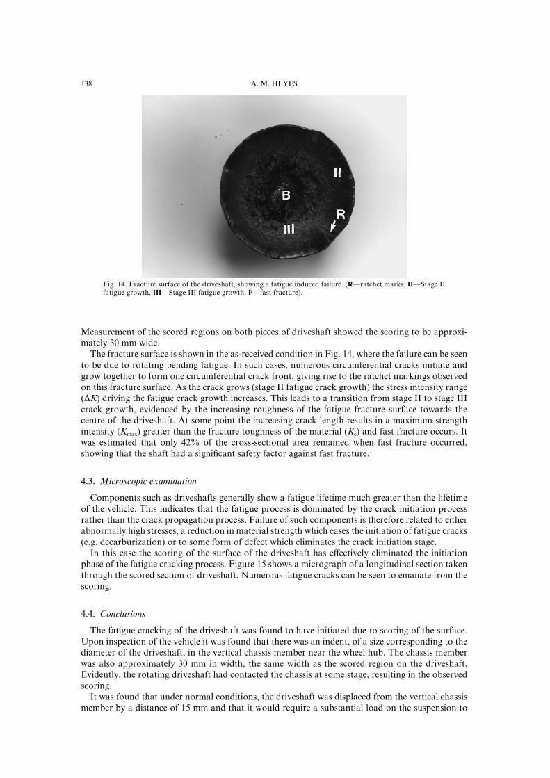
The section of driveshaft received for analysis measured approximately 59 cm in length and hadfailed just after a gradual change in section[ Close examination of the fractured end of the shaftshowed evident scoring "Fig[ 02#\ with light blue interference _lm oxides visible in this region[
Fig[ 02[ The fractured end of the driveshaft[ Note the scoring[
027 A[ M[ HEYES
Fig[ 03[ Fracture surface of the driveshaft\ showing a fatigue induced failure[ "R*ratchet marks\ II*Stage IIfatigue growth\ III*Stage III fatigue growth\ F*fast fracture#[
Measurement of the scored regions on both pieces of driveshaft showed the scoring to be approxi!mately 29 mm wide[
The fracture surface is shown in the as!received condition in Fig[ 03\ where the failure can be seento be due to rotating bending fatigue[ In such cases\ numerous circumferential cracks initiate andgrow together to form one circumferential crack front\ giving rise to the ratchet markings observedon this fracture surface[ As the crack grows "stage II fatigue crack growth# the stress intensity range"DK# driving the fatigue crack growth increases[ This leads to a transition from stage II to stage IIIcrack growth\ evidenced by the increasing roughness of the fatigue fracture surface towards thecentre of the driveshaft[ At some point the increasing crack length results in a maximum strengthintensity "Kmax# greater than the fracture toughness of the material "Kc# and fast fracture occurs[ Itwas estimated that only 31) of the cross!sectional area remained when fast fracture occurred\showing that the shaft had a signi_cant safety factor against fast fracture[
3[2[ Microscopic examination
Components such as driveshafts generally show a fatigue lifetime much greater than the lifetimeof the vehicle[ This indicates that the fatigue process is dominated by the crack initiation processrather than the crack propagation process[ Failure of such components is therefore related to eitherabnormally high stresses\ a reduction in material strength which eases the initiation of fatigue cracks"e[g[ decarburization# or to some form of defect which eliminates the crack initiation stage[
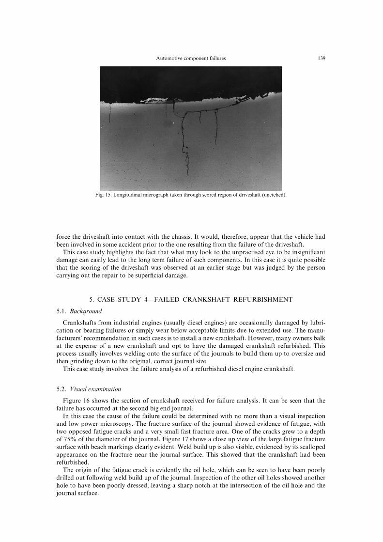
In this case the scoring of the surface of the driveshaft has e}ectively eliminated the initiationphase of the fatigue cracking process[ Figure 04 shows a micrograph of a longitudinal section takenthrough the scored section of driveshaft[ Numerous fatigue cracks can be seen to emanate from thescoring[
3[3[ Conclusions
The fatigue cracking of the driveshaft was found to have initiated due to scoring of the surface[Upon inspection of the vehicle it was found that there was an indent\ of a size corresponding to thediameter of the driveshaft\ in the vertical chassis member near the wheel hub[ The chassis memberwas also approximately 29 mm in width\ the same width as the scored region on the driveshaft[Evidently\ the rotating driveshaft had contacted the chassis at some stage\ resulting in the observedscoring[
It was found that under normal conditions\ the driveshaft was displaced from the vertical chassismember by a distance of 04 mm and that it would require a substantial load on the suspension to
028Automotive component failures
Fig[ 04[ Longitudinal micrograph taken through scored region of driveshaft "unetched#[
force the driveshaft into contact with the chassis[ It would\ therefore\ appear that the vehicle hadbeen involved in some accident prior to the one resulting from the failure of the driveshaft[
This case study highlights the fact that what may look to the unpractised eye to be insigni_cantdamage can easily lead to the long term failure of such components[ In this case it is quite possiblethat the scoring of the driveshaft was observed at an earlier stage but was judged by the personcarrying out the repair to be super_cial damage[
4[ CASE STUDY 3*FAILED CRANKSHAFT REFURBISHMENT
4[0[ Back`round
Crankshafts from industrial engines "usually diesel engines# are occasionally damaged by lubri!cation or bearing failures or simply wear below acceptable limits due to extended use[ The manu!facturers| recommendation in such cases is to install a new crankshaft[ However\ many owners balkat the expense of a new crankshaft and opt to have the damaged crankshaft refurbished[ Thisprocess usually involves welding onto the surface of the journals to build them up to oversize andthen grinding down to the original\ correct journal size[
This case study involves the failure analysis of a refurbished diesel engine crankshaft[
4[1[ Visual examination
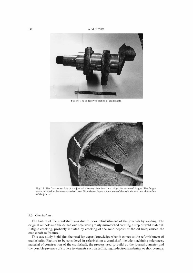
Figure 05 shows the section of crankshaft received for failure analysis[ It can be seen that thefailure has occurred at the second big end journal[
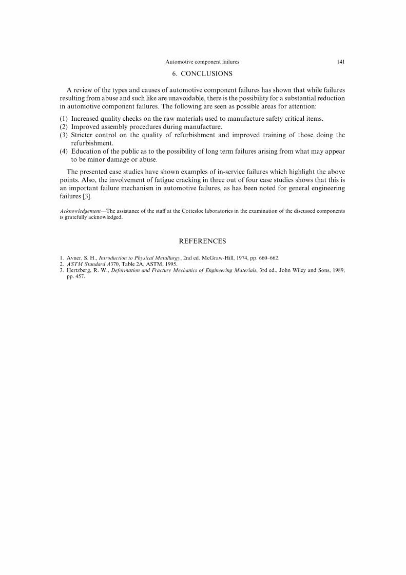
In this case the cause of the failure could be determined with no more than a visual inspectionand low power microscopy[ The fracture surface of the journal showed evidence of fatigue\ withtwo opposed fatigue cracks and a very small fast fracture area[ One of the cracks grew to a depthof 64) of the diameter of the journal[ Figure 06 shows a close up view of the large fatigue fracturesurface with beach markings clearly evident[ Weld build up is also visible\ evidenced by its scallopedappearance on the fracture near the journal surface[ This showed that the crankshaft had beenrefurbished[
The origin of the fatigue crack is evidently the oil hole\ which can be seen to have been poorlydrilled out following weld build up of the journal[ Inspection of the other oil holes showed anotherhole to have been poorly dressed\ leaving a sharp notch at the intersection of the oil hole and thejournal surface[
039 A[ M[ HEYES
Fig[ 05[ The as!received section of crankshaft[
Fig[ 06[ The fracture surface of the journal showing clear beach markings\ indicative of fatigue[ The fatiguecrack initiated at the mismatched oil hole[ Note the scalloped appearance of the weld deposit near the surfaceof the journal[
4[2[ Conclusions
The failure of the crankshaft was due to poor refurbishment of the journals by welding[ Theoriginal oil hole and the drilled out hole were grossly mismatched creating a step of weld material[Fatigue cracking\ probably initiated by cracking of the weld deposit at the oil hole\ caused thecrankshaft to fracture[
This case study highlights the need for expert knowledge when it comes to the refurbishment ofcrankshafts[ Factors to be considered in refurbishing a crankshaft include machining tolerances\material of construction of the crankshaft\ the process used to build up the journal diameter andthe possible presence of surface treatments such as tu}triding\ induction hardening or shot peening[
030Automotive component failures
5[ CONCLUSIONS
A review of the types and causes of automotive component failures has shown that while failuresresulting from abuse and such like are unavoidable\ there is the possibility for a substantial reductionin automotive component failures[ The following are seen as possible areas for attention]
"0# Increased quality checks on the raw materials used to manufacture safety critical items["1# Improved assembly procedures during manufacture["2# Stricter control on the quality of refurbishment and improved training of those doing the
refurbishment["3# Education of the public as to the possibility of long term failures arising from what may appear
to be minor damage or abuse[
The presented case studies have shown examples of in!service failures which highlight the abovepoints[ Also\ the involvement of fatigue cracking in three out of four case studies shows that this isan important failure mechanism in automotive failures\ as has been noted for general engineeringfailures ð2Ł[
Acknowled`ement*The assistance of the sta} at the Cottesloe laboratories in the examination of the discussed componentsis gratefully acknowledged[
REFERENCES
0[ Avner\ S[ H[\ Introduction to Physical Metallur`y\ 1nd ed[ McGraw!Hill\ 0863\ pp[ 559Ð551[1[ ASTM Standard A269\ Table 1A\ ASTM\ 0884[2[ Hertzberg\ R[ W[\ Deformation and Fracture Mechanics of En`ineerin` Materials\ 2rd ed[\ John Wiley and Sons\ 0878\
pp[ 346[