automation software package
TRANSCRIPT

Automation Software Package
AI Controller Standard Software
Operation Manual
SYSMAC-AICSTE££L
W611-E1-03

NOTE• All rights reserved. No part of this publication may be reproduced, stored in a retrieval system, or
transmitted, in any form, or by any means, mechanical, electronic, photocopying, recording, or oth-erwise, without the prior written permission of OMRON.
• No patent liability is assumed with respect to the use of the information contained herein.Moreover, because OMRON is constantly striving to improve its high-quality products, the informa-tion contained in this manual is subject to change without notice.
• Every precaution has been taken in the preparation of this manual. Nevertheless, OMRON as-sumes no responsibility for errors or omissions.Neither is any liability assumed for damages resulting from the use of the information contained inthis publication.
Trademarks• Sysmac and SYSMAC are trademarks or registered trademarks of OMRON Corporation in Japan
and other countries for OMRON factory automation products.• Microsoft, Windows, Excel, and Visual Basic are registered trademarks or trademarks of Microsoft
Corporation in the United States and other countries.
• EtherCAT® is registered trademark and patented technology, licensed by Beckhoff AutomationGmbH, Germany.
• The SD and SDHC logos are trademarks of SD-3C, LLC.
• Celeron, Intel, Intel Core are trademarks of Intel Corporation in the U.S. and/or other countries.
Other company names and product names in this document are the trademarks or registered trade-marks of their respective companies.
CopyrightsMicrosoft product screen shots reprinted with permission from Microsoft Corporation.

IntroductionThank you for purchasing the AI Controller Standard Software.This manual contains information that is necessary to use the AI Controller Standard Software. Pleaseread this manual and make sure you fully understand the functionality and performance before you at-tempt to use it in a control system.Keep this manual in a safe place where it will be available for reference during operation.
Intended AudienceThis manual is intended for the following personnel, who must also have knowledge of electrical sys-tems (an electrical engineer or the equivalent).• Personnel in charge of introducing FA systems.• Personnel in charge of designing FA systems.• Personnel in charge of installing and maintaining FA systems.• Personnel in charge of managing FA systems and facilities.For programming, this manual is intended for personnel who understand the programming languagespecifications in international standard IEC 61131-3 or Japanese standard JIS B 3503, and who haveknowledge about artificial intelligence.
NoticeThis manual contains information that is necessary to use the AI Controller Standard Software. Pleaseread and understand this manual before using the software. Keep this manual in a safe place where itwill be available for reference during operation.
Introduction
1AI Controller Standard Software Operation Manual (W611)

Manual Structure
Page Structure and SymbolsThe following page structure is used in this manual.
4-9
4 Installation and Wiring
NJ-series CPU Unit Hardware User’s Manual (W500)
sti
nU
gni
tn
uo
M
3-4
4
s tn
en
op
mo
C r
ellor
tn
oC
gni
tc
en
no
C
1-3-
4
4-3 Mounting Units
The Units that make up an NJ-series Controller can be connected simply by pressing the Units together
and locking the sliders by moving them toward the back of the Units. The End Cover is connected in the
same way to the Unit on the far right side of the Controller.
1 Join the Units so that the connectors fit exactly.
2 The yellow sliders at the top and bottom of each Unit lock the Units together. Move the sliders
toward the back of the Units as shown below until they click into place.
Precautions for Correct UsePrecautions for Correct Use
4-3-1 Connecting Controller Components
Connector
Hook Hook holes
Slider
Lock
Release
Move the sliders toward the back until they lock into place.
Level 1 heading
Level 2 heading
Level 3 headingLevel 2 heading
A step in a procedure
Manual name
Special information
Level 3 heading
Page tab
Gives the current
headings.
Indicates a procedure.
Icons indicate
precautions, additional
information, or reference
information.
Gives the number
of the main section.
This illustration is provided only as a sample. It may not literally appear in this manual.
The sliders on the tops and bottoms of the Power Supply Unit, CPU Unit, I/O Units, Special I/O
Units, and CPU Bus Units must be completely locked (until they click into place) after connecting
the adjacent Unit connectors.
Special InformationSpecial information in this manual is classified as follows:
Precautions for Safe UsePrecautions on what to do and what not to do to ensure safe usage of the product.
Precautions for Correct UsePrecautions on what to do and what not to do to ensure proper operation and performance.
Additional InformationAdditional information to read as required.
Manual Structure
2 AI Controller Standard Software Operation Manual (W611)

This information is provided to increase understanding or make operation easier.
Version InformationInformation on differences in specifications and functionality for Controller with different unit versionsand for different versions of the Sysmac Studio is given.
Precaution on Terminology• In this manual, "download" refers to transferring data from AI Controller Standard Software to a
physical AI Controller, and "upload" refers to transferring data from a physical AI Controller to the AIController Standard Software.
• In this manual, the functions of a specific model of the NX-series CPU Units/Controllers may be de-scribed with its model specified, such as "NX701 CPU Unit/Controller".
• In this manual, the Controller functions that are integrated in the NY-series Industrial PC may be re-ferred to as an "NY-series Controller".
• The AI Controller Standard Software supports the NX/NY-series Controllers. Unless another Con-troller series is specified, the operating procedures and screen captures used in the manual are ex-amples of the NY-series AI Controllers.
TerminologyFor descriptions of the Controller terms that are used in this manual, refer to information on terminolo-gy in the manuals that are listed in Related Manuals on page 18.
Manual Structure
3AI Controller Standard Software Operation Manual (W611)

Manual Structure
4 AI Controller Standard Software Operation Manual (W611)

Sections in this Manual
Sections in this Manual
5AI Controller Standard Software Operation Manual (W611)
1
2
3
4
5
6
A
I
6
2
1
3
4
A
I
Overview of the AI Controller Standard Software
Software Setup and Operation Flow
Description of the AI Operator Screen Components
Basic Software Configuration
Description of the AI Viewer Screen Components
Using AI Predictive Maintenance Library
Appendices
Index
5

CONTENTSIntroduction .............................................................................................................. 1
Intended Audience...........................................................................................................................................1Notice...............................................................................................................................................................1
Manual Structure...................................................................................................... 2Page Structure and Symbols ...........................................................................................................................2Special Information ..........................................................................................................................................2Precaution on Terminology ..............................................................................................................................3Terminology .....................................................................................................................................................3
Sections in this Manual ........................................................................................... 5
Terms and Conditions Agreement.......................................................................... 9
Safety Precautions................................................................................................. 11Definition of Precautionary Information.......................................................................................................... 11Symbols ......................................................................................................................................................... 11WARNINGS ...................................................................................................................................................12Cautions.........................................................................................................................................................12
Precautions for Safe Use ...................................................................................... 13
Precautions for Correct Use ................................................................................. 14
Regulations and Standards .................................................................................. 15Software Licenses and Copyrights ................................................................................................................15
Versions .................................................................................................................. 16Checking Versions .........................................................................................................................................16
Related Manuals..................................................................................................... 18
Revision History..................................................................................................... 19
Section 1 Overview of the AI Controller Standard Software1-1 The AI Controller Standard Software ...................................................................................1-21-2 Specifications.........................................................................................................................1-3
Section 2 Software Setup and Operation Flow2-1 Confirmations before Installation.........................................................................................2-22-2 Installation Procedure ...........................................................................................................2-32-3 Uninstallation Procedure ......................................................................................................2-42-4 Usage Flow.............................................................................................................................2-5
CONTENTS
6 AI Controller Standard Software Operation Manual (W611)

Section 3 Basic Software Configuration3-1 Window Configuration...........................................................................................................3-23-2 List of the AI Operator Functions.........................................................................................3-33-3 List of the AI Viewer Functions ............................................................................................3-43-4 Connecting to the AI Controller............................................................................................3-5
Section 4 Description of the AI Operator Screen Components4-1 Creating an AI Controller Project .........................................................................................4-2
4-1-1 Starting and Exiting the AI Operator ...........................................................................................4-24-1-2 Creating a New AI Controller Project ..........................................................................................4-24-1-3 Opening an AI Controller Project ................................................................................................4-44-1-4 Editing Properties of an AI Controller Project..............................................................................4-5
4-2 Setting Variable Data .............................................................................................................4-64-3 Setting Equipment Event ......................................................................................................4-94-4 AI Machine Learning Model ................................................................................................ 4-11
4-4-1 Export Dialog.............................................................................................................................4-12
4-5 Setting WebAPI Connection Function ...............................................................................4-144-5-1 Basic Settings of the WebAPI Connection Function .................................................................4-144-5-2 Certificate Settings for WebAPI Connection..............................................................................4-154-5-3 Detailed View of Trusted Certificates ........................................................................................4-16
4-6 Collecting Variable Data ......................................................................................................4-184-7 Detailed Settings for Data Collection.................................................................................4-194-8 Monitor and Operation ........................................................................................................4-204-9 Mode Changes .....................................................................................................................4-254-10 Collective Comparison........................................................................................................4-264-11 Collective Uploading ...........................................................................................................4-284-12 Statistical Information .........................................................................................................4-294-13 Authority Verification for AI Controller Operation ............................................................4-34
Section 5 Description of the AI Viewer Screen Components5-1 Creating an AI Viewer Project...............................................................................................5-2
5-1-1 Starting and Shutting Down the AI Viewer ..................................................................................5-25-1-2 Creating a New AI Viewer Project ...............................................................................................5-25-1-3 Opening an AI Viewer Project .....................................................................................................5-3
5-2 Placing Equipment Events....................................................................................................5-55-2-1 Placing Equipment Events to Designated Locations...................................................................5-65-2-2 Group Settings ............................................................................................................................5-65-2-3 Specifying the Number of Equipment Events on a Single Window.............................................5-7
5-3 Monitor and Operation ..........................................................................................................5-95-4 Monitoring Equipment Events ............................................................................................5-10
5-4-1 Displaying History .....................................................................................................................5-125-4-2 Displaying the Trend Graph ......................................................................................................5-13
CONTENTS
7AI Controller Standard Software Operation Manual (W611)

Section 6 Using AI Predictive Maintenance Library6-1 Installing AI Predictive Maintenance Library ......................................................................6-26-2 Registering License for AI Predictive Maintenance Library ..............................................6-46-3 Registering Equipment Events by Using the AI Predictive Maintenance Library
to the AI Operator ..................................................................................................................6-56-4 Checking the Versions of the AI Predictive Maintenance Library.....................................6-7
AppendicesA-1 Errors and Troubleshooting................................................................................................. A-2
Index
CONTENTS
8 AI Controller Standard Software Operation Manual (W611)
Terms and Conditions Agreement
WARRANTY• The warranty period for the Software is one year from the date of purchase, unless otherwise specif-
ically agreed.• If the User discovers defect of the Software (substantial non-conformity with the manual), and return
it to OMRON within the above warranty period, OMRON will replace the Software without charge byoffering media or download from OMRON’s website. And if the User discovers defect of mediawhich is attributable to OMRON and return it to OMRON within the above warranty period, OMRONwill replace defective media without charge. If OMRON is unable to replace defective media or cor-rect the Software, the liability of OMRON and the User’s remedy shall be limited to the refund of thelicense fee paid to OMRON for the Software.
LIMITATION OF LIABILITY• THE ABOVE WARRANTY SHALL CONSTITUTE THE USER’S SOLE AND EXCLUSIVE REM-
EDIES AGAINST OMRON AND THERE ARE NO OTHER WARRANTIES, EXPRESSED OR IM-PLIED, INCLUDING BUT NOT LIMITED TO, WARRANTY OF MERCHANTABILITY OR FITNESSFOR PARTICULAR PURPOSE. IN NO EVENT, OMRON WILL BE LIABLE FOR ANY LOST PROF-ITS OR OTHER INDIRECT, INCIDENTAL, SPECIAL OR CONSEQUENTIAL DAMAGES ARISINGOUT OF USE OF THE SOFTWARE.
• OMRON SHALL HAVE NO LIABILITY FOR DEFECT OF THE SOFTWARE BASED ON MODIFICA-TION OR ALTERNATION TO THE SOFTWARE BY THE USER OR ANY THIRD PARTY. OMRONSHALL NOT BE RESPONSIBLE AND/OR LIABLE FOR ANY LOSS, DAMAGE, OR EXPENSES DI-RECTLY OR INDIRECTLY RESULTING FROM THE INFECTION OF OMRON PRODUCTS, ANYSOFTWARE INSTALLED THEREON OR ANY COMPUTER EQUIPMENT, COMPUTER PRO-GRAMS, NETWORKS, DATABASES OR OTHER PROPRIETARY MATERIAL CONNECTEDTHERETO BY DISTRIBUTED DENIAL OF SERVICE ATTACK, COMPUTER VIRUSES, OTHERTECHNOLOGICALLY HARMFUL MATERIAL AND/OR UNAUTHORIZED ACCESS.
• OMRON SHALL HAVE NO LIABILITY FOR SOFTWARE DEVELOPED BY THE USER OR ANYTHIRD PARTY BASED ON THE SOFTWARE OR ANY CONSEQUENCE THEREOF.
APPLICABLE CONDITIONSUSER SHALL NOT USE THE SOFTWARE FOR THE PURPOSE THAT IS NOT PROVIDED IN THEATTACHED USER MANUAL.
CHANGE IN SPECIFICATIONThe software specifications and accessories may be changed at any time based on improvements andother reasons.
Terms and Conditions Agreement
9AI Controller Standard Software Operation Manual (W611)

ERRORS AND OMISSIONSThe information in this manual has been carefully checked and is believed to be accurate; however, noresponsibility is assumed for clerical, typographical, or proofreading errors, or omissions.
Terms and Conditions Agreement
10 AI Controller Standard Software Operation Manual (W611)

Safety Precautions
Definition of Precautionary InformationThe following notation is used in this manual to provide precautions required to ensure safe usage ofthe AI Controller Standard Software and the Artificial Intelligence Machine Automation Controllers.The safety precautions that are provided are extremely important to safety. Always read and heed theinformation provided in all safety precautions.The following notation is used.
WARNINGIndicates a potentially hazardous situation which, if not avoid-ed, could result in death or serious injury. Additionally, theremay be severe property damage.
CAUTIONIndicates a potentially hazardous situation which, if not avoid-ed, may result in minor or moderate injury, or property damage.
Precautions for Safe UseIndicates precautions on what to do and what not to do to ensure safe usage of the product.
Precautions for Correct UseIndicates precautions on what to do and what not to do to ensure proper operation and performance.
SymbolsThe symbol indicates operations that you must not do.
The specific operation is shown in the symbol and explained in text.
This example indicates prohibiting disassembly.
The r symbol indicates precautions (including warnings).The specific operation is shown in the r symbol and explained in text.This example indicates a precaution for electric shock.
The r symbol indicates precautions (including warnings).The specific operation is shown in the r symbol and explained in text.This example indicates a general precaution.
The l symbol indicates operations that you must do.The specific operation is shown in the l symbol and explained in text.This example shows a general precaution for something that you mustdo.
Safety Precautions
11AI Controller Standard Software Operation Manual (W611)

WARNINGS
WARNINGCheck the parameters for proper execution before you use them for actual operation.
Always confirm safety at the destination node before you transfer parameters from theAI Controller Standard Software. The devices or machines may perform unexpectedoperations regardless of the operating mode of the CPU Unit.
Cautions
Caution
Always confirm safety at the destination node before you transfer parameters or datato a node from the AI Controller Standard Software.Not doing so may result in injury.
Safety Precautions
12 AI Controller Standard Software Operation Manual (W611)

Precautions for Safe Use
Operation• Confirm that the controlled system will not be adversely affected before you perform any of the fol-
lowing operations.a) Changing the operating mode of the CPU Unit (including changing the Startup Mode)b) Change the settings
• Before you use the system for the actual operation, make sure to verify that errors can be correctlydetected by using the results analyzed by this tool. Upon verification, set the machine learning en-gine to start reading learning data and parameters. Inappropriate settings will result in misjudgingerrors.
• Before you start the operation, make sure to transfer parameters and data necessary for resumingthe operation to the replaced CPU Unit.
• When you restore only part of the data that was backed up, confirm that no problems will occur ifyou do not restore all of the backup data. Otherwise, malfunction of the device may occur.
Unit Replacement• The performance may be different if the hardware revisions are different. Before you transfer the
user program, data, and parameter settings to the CPU Units with the different hardware revisions,check them for proper execution and then use them for actual operation.
Precautions for Safe Use
13AI Controller Standard Software Operation Manual (W611)
Precautions for Correct UseObserve the following precautions before you start the AI Controller Standard Software or any of theSupport Software that is provided with it.• Exit all applications that are not necessary to use the AI Controller Standard Software. For virus
checker or other software that could affect the startup and operations of the AI Controller StandardSoftware, take measures such as to remove the AI Controller Standard Software from the scope ofvirus checking.
• If any hard disks or printers that are connected to the computer are shared with other computers ona network, isolate them so that they are no longer shared.
• With some notebook computers, the default settings do not supply power to the USB port or Ether-net port to save energy. There are energy-saving settings in Windows, and also sometimes disableall energy-saving features. Refer to the user documentation for your computer and disable all ener-gy-saving features.
Precautions for Correct Use
14 AI Controller Standard Software Operation Manual (W611)

Regulations and Standards
Software Licenses and CopyrightsThis product incorporates certain third party software. The license and copyright information associat-ed with this software is available at ThirdPartyLicenses.txt in DVD media.
Regulations and Standards
15AI Controller Standard Software Operation Manual (W611)

VersionsHardware revisions and unit versions are used to manage the hardware and software in NX/NY-seriesUnits and EtherCAT slaves. The hardware revision or unit version is updated each time there is achange in hardware or software specifications. Even when two Units or EtherCAT slaves have thesame model number, they will have functional or performance differences if they have different hard-ware revisions or unit versions.
Checking VersionsYou can check versions on the ID information indications or with the Sysmac Studio.
Checking Unit Versions on ID Information IndicationsThe unit version is given on the ID information indication on the side of the product.
l Checking the Unit Version of an NX-series CPU UnitThe ID information on an NX-series NX701-Z£££ CPU Unit is shown below.
ID information indication
Lot number
LOT No. DDMYY xxxx Ver.1.
PORT1 :
PORT2 :
MAC address
AIC Ver.1.££ AI Controller version
Unit versionSerial number
l Checking the Unit Version of an NY-series ControllerThe ID information on an NY-series NY5£2-Z£££ Controller is shown below.
ID information indication
Ver. X.XXLOT No. DDMYY£ AIC Ver.1.££
AI Controller versionUnit version
Serial number
<<<<
Versions
16 AI Controller Standard Software Operation Manual (W611)

Checking Unit Versions with the Sysmac StudioYou can use the Sysmac Studio to check unit versions. The procedure is different for Units and forEtherCAT slaves.
l Checking the Unit Version of an NX-series CPU UnitYou can use the Production Information while the Sysmac Studio is online to check the unit ver-sion of a Unit. You can do this for the following Unit.
Model Unit for which version can be checkedNX701-££££ CPU Unit
1 Right-click CPU Rack under Configurations and Setup - CPU/Expansion Racks in the Multi-view Explorer and select Display Production Information.The Production Information Dialog Box is displayed.
l Checking the Unit Version of an NY-series ControllerYou can use the Production Information while the Sysmac Studio is online to check the unit ver-sion of a Unit. You can only do this for the Controller.
1 Right-click CPU Rack under Configurations and Setup - CPU/Expansion Racks in the Multi-view Explorer and select Display Production Information.The Production Information Dialog Box is displayed.
l Changing Information Displayed in Production Information Dialog Box
1 Click the Show Outline or Show Detail Button at the lower right of the ProductionInformation Dialog Box.The view will change between the Production Information details and outline.
Outline View Detail View
The information displayed is different for the Outline View and the Detail View. The Detail Viewdisplays both the unit version and the AI Controller version. The Outline View displays only theunit versions.
Note The hardware revision is separated by “/” and is displayed on the right of the hardware version. Thehardware revision is not displayed for the Unit that the hardware revision is in blank.
Versions
17AI Controller Standard Software Operation Manual (W611)

Related ManualsThe following manuals are related. Use these manuals for reference.
Manual name Cat. No. Model numbers Application DescriptionNJ/NX-series CPU UnitSoftware User’s Manual
W501 NX701-££££NX102-££££NX1P2-££££NJ501-££££NJ301-££££NJ101-££££
Learning how to pro-gram and set up anNJ/NX-series CPUUnit.Mainly software infor-mation is provided.
The following information is provided on aController built with an NJ/NX-series CPUUnit.• CPU Unit operation• CPU Unit features• Initial settings• Programming based on IEC 61131-3
language specificationsSysmac Studio Version 1Operation Manual
W504 SYSMAC-SE2£££
Learning about theoperating proceduresand functions of theSysmac Studio.
Describes the operating procedures of theSysmac Studio.
NX/NY-seriesArtificial Intelligence MachineAutomation ControllerUser’s Manual
W594 NZ701-Z£££NY532-Z£££NY512-Z£££
Learning about theNX/NY-series AI-equipped MachineAutomation Control-lers
This manual describes the overview of theNX/NY-series Artificial Intelligence MachineAutomation Controllers, the specificationsof the AI functions, how to start the system,and maintenance and error details.
NY-seriesIPC Machine ControllerIndustrial Panel PC / Industri-alBox PCSoftware User’s Manual
W558 NY532-££££NY512-££££
Learning how to pro-gram and set up theController functionsof an NY-series In-dustrial PC.
The following information is provided onthe NY-series Controller functions.• Controller operation• Controller features• Controller settings• Programming based on IEC 61131-3
language specificationsAI Controller Data MiningSoftware Operation Manual
W612 SYSMAC-AIC-STENGE££L
Learning the outlineand usage of the AIController Data Min-ing Software
The manual describes the outline of the AIController Data Mining Software (AI EasyModeler, AI Easy Modeler for Model Set-ting), installation method, basic operations,connection, and operations of the mainfeatures.
Sysmac Library AI PredictiveMaintenance Library User’sManual
W610 SYSMAC-ZPA00£000W
Learning about thespecifications of theAI Predictive Mainte-nance Libraries andfunction blocks
Information necessary in using AI predic-tive maintenance library is described.
Related Manuals
18 AI Controller Standard Software Operation Manual (W611)

Revision HistoryA manual revision code appears as a suffix to the catalog number on the front and back covers of themanual.
W611-E1-03
Revision code
Cat. No.
Revision code Date Revised content01 October 2018 Original production02 July 2019 Revisions for improving description relating to equipment events.03 April 2021 Revisions for an upgrade to AI Controller Standard Software version 1.1.
Revision History
19AI Controller Standard Software Operation Manual (W611)

Revision History
20 AI Controller Standard Software Operation Manual (W611)

1Overview of the AI ControllerStandard Software
This section provides an overview and lists the specifications of the AI ControllerStandard Software and describes its features and components.
1-1 The AI Controller Standard Software ........................................................... 1-21-2 Specifications................................................................................................. 1-3
1-1AI Controller Standard Software Operation Manual (W611)
1

1-1 The AI Controller Standard SoftwareThe AI Controller Standard Software is a software package designed to provide tools for installing theAI-embedded Machine Automation Controller (AI Controller to be short) and for the operation of theinstalled controller. The AI Controller Standard Software consisting of the AI Operator, the AI Viewerand the AI licence registration software runs on Windows. These tools are used in each phase of theAI Controller including data collection, data analysis, and data utilization.The AI Controller Standard Software is designed to provide optimum functionality and operability whenit is used with the AI Controller, and the automation software called Sysmac Studio.Refer to NX/NY-series Artificial Intelligence Machine Automation Controller User’s Manual (Cat. No.W594) for the system configuration of the AI Controllers.
Main Features
l Making Data Collection, Data Analysis, and Data Utilization EasierThe AI Operator is a tool allowing you to transfer settings for the AI Controller’s AI functions as wellas to monitor the status. In addition, it is equipped with a function allowing you to transfer analysisdata, feature data, and equipment event monitoring score data from the AI Controller to your com-puter. (Even if you are logged off from Windows, the transfer can be executed as Windows serv-ices.)The functions are configured for the following use cases.• Data Collection: Collects analysis data• Data Analysis: Generates data necessary for monitoring equipment events• Data Utilization: Transfers a CSV file to a computer and monitors equipment events/transfers da-
ta to a web server.
l Easy OperationThe AI Viewer is a tool allowing users to visualize results of equipment event monitoring that wasperformed by the Feature Value/Machine Learning Function. This tool makes it easy for users toview monitoring results without the need for the controller programming knowledge.
1 Overview of the AI Controller Standard Software
1-2 AI Controller Standard Software Operation Manual (W611)

1-2 Specifications
Product Model NumbersThe product AI Controller Data Mining Software consists of a DVD media and a license, each of whichis given a model number.If you are purchasing the AI Controller Data Mining Software for the first time, purchase both a DVDand one or more licenses. The media is the same for all of the licenses. If you are purchasing theproduct for additional licenses, you can purchase only the licenses. You can also purchase the DVDseparately.The DVD is not included with the licenses.
l DVD
Product Media Model numberAI Controller Standard SoftwareVer.1.££
DVD SYSMAC-AICSTE00D
l Licenses
Product Number of licenses Model numberAI Controller Standard SoftwareVer.1.££
1 license SYSMAC-AICSTE01L10 licenses SYSMAC-AICSTE10L30 licenses SYSMAC-AICSTE30L50 licenses SYSMAC-AICSTE50L
Support Software That You Can Install from the DVD media of AIController Standard Software and Enclosed Data
The following table lists the Support Software that you can install from the DVD media of AI ControllerStandard Software and the data that is included in the DVD media.
Installable Software VersionAI Operator Ver.1.£AI Viewer Ver.1.£AI License Registration Software Ver.1.£
Supported LanguagesAI Controller Standard Software supports the following languages.Japanese, English
Applicable ModelsThe models that you can select when you create a project on the AI Controller Standard Software aregiven in the following tables.
1 Overview of the AI Controller Standard Software
1-3AI Controller Standard Software Operation Manual (W611)
1-2 Specifications
1

Model numbers Unit versionNX701-Z£00 Ver.1.18 or laterNY5£2-Z£00 Ver.1.18 or later
Applicable ComputersThe AI Controller Standard Software is a Microsoft Windows-based software.The supported operating systems are listed below.• Windows 7 (32-bit or 64-bit edition)• Windows Embedded Standard 7 (64-bit edition)• Windows 10 (32-bit or 64-bit edition)Apply the latest updates to the OS installed on your computer to ensure that it is always up-to-date.
Installation of the following applications is a system requirement for the AI Controller Standard Soft-ware.• .NET Framework3.5• .NET Framework4.6.1It is installed automatically if it is not already installed on the computer when the AI Controller Stand-ard Software is installed.
l System RequirementsThe system requirements for the AI Controller Standard Software are given in the following table.
OS CPU RAM DisplayWindows 7 (32-bit or 64-bitedition)Windows Embedded Stand-ard 7 (64-bit edition)(NY-series IPC Machine Con-troller)Windows 10 (32-bit or 64-bitedition)Windows 10 IoT Enterprise2019 (64-bit edition)(NY-series IPC Machine Con-troller)
Re-quired
IBM AT or compatible with Intel® Celeron®processor 540 (1.8 GHz)
2 GB XGA1024 x 76816 million colors
Recom-mended
IBM AT or compatible with Intel® Core™ i5M520 processor (2.4 GHz) or the equiva-lent
4 GB ormore
WXGA1280 x 80016 million colors
In addition, the following are also required.
System requirement SpecificationFree HDD space required for software installation 4.6 GB or moreOptical drive type DVD-ROM driveCommunications port Ethernet
1 Overview of the AI Controller Standard Software
1-4 AI Controller Standard Software Operation Manual (W611)
2Software Setup and OperationFlow
This chapter describes the procedure to install and uninstall the AI Controller StandardSoftware, and usage flow.
2-1 Confirmations before Installation................................................................. 2-22-2 Installation Procedure ................................................................................... 2-32-3 Uninstallation Procedure............................................................................... 2-42-4 Usage Flow ..................................................................................................... 2-5
2-1AI Controller Standard Software Operation Manual (W611)
2

2-1 Confirmations before InstallationCheck the following items before you install the AI Controller Standard Software.• To install the AI Controller Standard Software, log onto Windows as the administrator or as a user
with administrator rights. There are files that a user without administrator rights cannot write. An ac-cess error will occur if you log on without administrator rights.
• Apply the latest updates to the OS to ensure that it is always up-to-date.• Exit all applications that are running on the computer before you install the AI Controller Standard
Software.• You cannot install the AI Controller Standard Software from a network drive, such as a DVD drive or
hardware drive that is shared on a network. Always install the AI Controller Standard Software froma DVD drive on the computer onto which you need to install the AI Controller Standard Software.
• Corrupted files cannot be restored on a compressed drive. Do not install the AI Controller StandardSoftware on a compressed drive.
• Do not cancel the setup while it is in progress. Files that were copied may remain in the installationdirectory.
• Do not turn OFF the power to the computer or reset the computer while the installation is in prog-ress. Computer data may be corrupted.
• You may need to restart Windows after you install the AI Controller Standard Software. Restart asrequired according to Installation Wizard messages.
2 Software Setup and Operation Flow
2-2 AI Controller Standard Software Operation Manual (W611)

2-2 Installation Procedure
1 Start Windows and insert the installation disk into the DVD- ROM drive.The setup program starts automatically and the Select Setup Language dialog box appears.
Additional Information
• If .NET Framework is not installed on the computer, the .NET Framework Installation dialogbox is displayed. Follow the instructions to install it.
• When .NET Framework is installed, a confirmation dialog box to restart the computer is dis-played. Always click the Yes button to restart the computer. After the computer is restarted,the Setup Wizard will automatically continue to the next step.
2 Follow the instructions shown on the screen to install the software.
Precautions for Correct Use
To create a project and select an AI Controller model on Sysmac Studio, you need to register alicense number for the AI Controller Standard Software on Sysmac Studio’s license screen.Refer to 3-3-12 Displaying and Registering Licenses of the Sysmac Studio Version 1 OperationManual (Cat. No. W504) for detailed procedure to register license.Refer to the file below in the NY-series AI Controllers.D:\OMRON-NY\Installers\AI_Controller_Standard_Software\README.txt
Additional Information
• For the NY-series AI Controllers, the setup program is stored in the Windows folder below.Start setup.exe and begin installation.D:\OMRON-NY\Installers\AI_Controller_Standard_Software
• When you install the AI Controller Standard Software to an NY-series AI Controller, you don'thave to register a license number.
2 Software Setup and Operation Flow
2-3AI Controller Standard Software Operation Manual (W611)
2-2 Installation Procedure
2

2-3 Uninstallation Procedure
1 Open Windows Control Panel*1 and select Add or Remove Programs.
2 Select AI Controller Standard Software and uninstall the application.
*1. The procedure for opening Control Panel differs depending on the operating system.Windows 7: Select Control Panel from the Start menuWindows10: Right-click the Start button and select Control Panel.
2 Software Setup and Operation Flow
2-4 AI Controller Standard Software Operation Manual (W611)

2-4 Usage FlowFor the startup procedure of the AI Controllers, refer to Section 6 Startup Procedure for the AI Control-ler in NX/NY-series Artificial Intelligence Machine Automation Controller User’s Manual (Cat. No.W594).
For the build procedure of an AI machine learning model, refer to 2-2 Basic Flow of Operation in AIController Data Mining Software Operation Manual (Cat. No. W612).
2 Software Setup and Operation Flow
2-5AI Controller Standard Software Operation Manual (W611)
2-4 Usage Flow
2

2 Software Setup and Operation Flow
2-6 AI Controller Standard Software Operation Manual (W611)
3Basic Software Configuration
This section describes the basic configurations of AI Operator and AI Viewer.
3-1 Window Configuration................................................................................... 3-23-2 List of the AI Operator Functions ................................................................. 3-33-3 List of the AI Viewer Functions..................................................................... 3-43-4 Connecting to the AI Controller .................................................................... 3-5
3-1AI Controller Standard Software Operation Manual (W611)
3

3-1 Window ConfigurationThe application window in AI Operator and AI Viewer consists of the title bar, main menu, sub menuthat appears according to the function selected in the main menu, and setting and monitoring area.The function overview of each area is described below.
Title BarMain Menu
Connection Target
Information Area
Sub Menu Settings and Monitoring Area
Area name Outline of functionTitle Bar Displays the open project name and software name in the following format.
Project Name - Controller Name (Serial No.) - Software NameExample: MyProject - new_Controller(1234) - AI Operator
Main Menu Displays a list of functions.The specifications for buttons are as follows:• When you press a button for each function, the Settings and Monitoring Area is
updated.• If the Settings and Monitoring Area has been updated, a confirmation dialog to
save the information appears before transiting to another screen.Sub Menu If more than one function is selected in the main menu, a list of the functions will
appear.• The specifications for buttons are same as those for the main menu.
Settings and MonitoringArea
You can specify various settings and perform monitoring. The Trnsfr Sttngs from/toController, and Compare Settings buttons are located at the bottom of the Settingsand Monitoring Area.
Connection Target Infor-mation Area
When communications with the AI Controller are in progress, the connected AIController’s IP address, Controller name, and serial number are displayed here.
3 Basic Software Configuration
3-2 AI Controller Standard Software Operation Manual (W611)
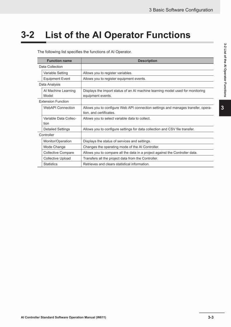
3-2 List of the AI Operator FunctionsThe following list specifies the functions of AI Operator.
Function name DescriptionData Collection
Variable Setting Allows you to register variables.Equipment Event Allows you to register equipment events.
Data Analysis
AI Machine LearningModel
Displays the import status of an AI machine learning model used for monitoringequipment events.
Extension Function
WebAPI Connection Allows you to configure Web API connection settings and manages transfer, opera-tion, and certificates.
Variable Data Collec-tion
Allows you to select variable data to collect.
Detailed Settings Allows you to configure settings for data collection and CSV file transfer.Controller
Monitor/Operation Displays the status of services and settings.Mode Change Changes the operating mode of the AI Controller.Collective Compare Allows you to compare all the data in a project against the Controller data.Collective Upload Transfers all the project data from the Controller.Statistics Retrieves and clears statistical information.
3 Basic Software Configuration
3-3AI Controller Standard Software Operation Manual (W611)
3-2 List of the AI O
perator Functions
3

3-3 List of the AI Viewer FunctionsThe following table lists the AI Viewer functions.
Function name DescriptionEvent Placement
Screen Placement Allows you to register an equipment event or a group of multiple equipmentevents at the position of a button.
Group Settings Allows you to register, edit, and delete a group.Number of Events Setting Allows you to specify the number of events displayed on the event status monitor-
ing screen.Monitor/Operation Allows you to start and stop the transfer of a CSV file containing equipment event
monitoring scores and feature values for each AI Controller.Event Monitoring
Event Status Monitoring Displays equipment event monitoring results.History Displays the history of Alrt Lv2 and Alrt Lv1.Trend Graph Displays the trend of equipment event monitoring scores and feature values.
3 Basic Software Configuration
3-4 AI Controller Standard Software Operation Manual (W611)

3-4 Connecting to the AI ControllerFor the NX-series AI Controllers, the AI Controller connection is supported only when you use thebuilt-in EtherNet/IP port while specifying the IP address.For the NY-series AI Controllers, communications are established by using the EtherNet/IP port that isbuilt into the Controller or by using the internal communications port.Note that the AI Operator and the AI Viewer do not have the equivalent status to online connection onthe Sysmac Studio. Depending on the function you use, you can establish a connection to the AI Con-troller automatically and perform operations on the AI Controller.For detailed information on connection configuration between an AI Controller and AI Operator/AIViewer, refer to 1-3 System Configuration of the NX/NY-series Artificial Intelligence MachineAutomation Controller User’s Manual (Cat. No. W594).
3 Basic Software Configuration
3-5AI Controller Standard Software Operation Manual (W611)
3-4 Connecting to the A
I Controller
3

3 Basic Software Configuration
3-6 AI Controller Standard Software Operation Manual (W611)

4Description of the AI OperatorScreen Components
This section describes names and functions of the AI Operator screen components.
4-1 Creating an AI Controller Project ................................................................. 4-24-1-1 Starting and Exiting the AI Operator................................................................ 4-24-1-2 Creating a New AI Controller Project .............................................................. 4-24-1-3 Opening an AI Controller Project..................................................................... 4-44-1-4 Editing Properties of an AI Controller Project.................................................. 4-5
4-2 Setting Variable Data ..................................................................................... 4-64-3 Setting Equipment Event............................................................................... 4-94-4 AI Machine Learning Model......................................................................... 4-11
4-4-1 Export Dialog................................................................................................. 4-12
4-5 Setting WebAPI Connection Function........................................................ 4-144-5-1 Basic Settings of the WebAPI Connection Function ..................................... 4-144-5-2 Certificate Settings for WebAPI Connection.................................................. 4-154-5-3 Detailed View of Trusted Certificates ............................................................ 4-16
4-6 Collecting Variable Data .............................................................................. 4-184-7 Detailed Settings for Data Collection ......................................................... 4-194-8 Monitor and Operation................................................................................. 4-204-9 Mode Changes.............................................................................................. 4-254-10 Collective Comparison ................................................................................ 4-264-11 Collective Uploading.................................................................................... 4-284-12 Statistical Information ................................................................................. 4-294-13 Authority Verification for AI Controller Operation .................................... 4-34
4-1AI Controller Standard Software Operation Manual (W611)
4

4-1 Creating an AI Controller ProjectThis section describes the AI OperatorAI Operator's basic operation, such as the procedure of startingand shutting down the AI Operator, how to create a new project, and how to save a project.
4-1-1 Starting and Exiting the AI Operator
Starting the AI Operator
1 Use the following procedure to start the AI Operator.• On Windows, select Start - All Programs - OMRON - AI Controller Standard Software
and then select AI Operator.The AI Operator starts up.
Exiting the AI Operator
1 Click the x button on the right end of the title bar.The AI Operator will close.
4-1-2 Creating a New AI Controller ProjectTo perform data collection and data analysis on the AI Controller, you need to create an AI Controllerproject on the AI Operator. This section describes the procedure to create a new AI Controller project.Select New Project to open the New Project screen. Next, specify each item and click the Createbutton.
4 Description of the AI Operator Screen Components
4-2 AI Controller Standard Software Operation Manual (W611)

(A)
(B)
Sym-bol Item Description
(A) Project Properties Allows you to enter the settings for a new AI Controller project. Shown beloware the settings you can specify and their default values.• Project name
Default: AnalysisBase• Author
Default: Author• Comment
Default: AnalysisProjectComment• AI Controller model
Default: NY512-Z300Options: NY512-Z300, NY512-Z400, NY512-Z500, NY532-Z300, NY532-Z400, NY532-Z500, NX701-Z600, NX701-Z700
• VersionDefault: 1.18Selected value: 1.18
• IP addressDefault: 192.168.254.1
• FTP PortDefault: 21
• FTP user nameDefault: None
• FTP PasswordDefault: None
(B) Create button The Variable Settings screen opens.
4 Description of the AI Operator Screen Components
4-3AI Controller Standard Software Operation Manual (W611)
4-1 Creating an A
I Controller Project
4
4-1-2 Creating a N
ew AI C
ontroller Project

Precautions for Correct Use
To be able to use an analysis data file and an equipment event monitoring score file that arestored in the AI Controller’s storage on the AI Operator and the AI Viewer, you will use the FTPcommunication protocol for transferring data files. The AI Controller is equipped with the FTPserver function. You need to configure the FTP server settings in advance. Be sure to set upyour FTP user name and password in the Controller settings of Sysmac Studio.
4-1-3 Opening an AI Controller ProjectThis section describes the procedure to open an existing AI Controller Project.Select Open Project to open the AI Controller Project List screen. Next, go to AI Controller ProjectList and select an AI Controller project. Then, click the Open button.
(A)
(B)
(D) (E)(C)
Sym-bol Item Description
(A) AI Controller ProjectList
Shows the list of AI Controller projects in the tree view.Display format:• The higher hierarchy is the Controller Name (Serial ID)• The lower hierarchy is the project name.
(B) Project Properties Displays the properties of a project selected in AI Controller project list.(C) Edit Properties button Opens the screen to edit project for a project selected in AI Controller project
list.(D) Delete button Deletes a project selected in AI Controller project list.(E) Open button Opens a project selected in AI Controller project list.
When you click this button, the Variable Settings screen opens.
4 Description of the AI Operator Screen Components
4-4 AI Controller Standard Software Operation Manual (W611)

Additional Information
The AI Controller project data is stored under C:\OMRON\Application\AIOperator\SettingPro-jects\AnalysisProjects\[Serial_No.]\[Project_Name]. To use an AI Controller project you createdhere on another computer, find a folder named the same as the project you want to use andcopy the entire folder.
4-1-4 Editing Properties of an AI Controller ProjectThis section describes the procedure to edit properties of an AI Controller project.Select a project from AI Controller Project List and click the Edit Properties button as described in 4-1-3 Opening an AI Controller Project on page 4-4.
(A)
(B) (C)
Sym-bol Item Description
(A) Project Properties Allows you to edit the setting on AI Controller projects.(B) Application button Applies the changes.(C) Cancel button Cancels the changes.
4 Description of the AI Operator Screen Components
4-5AI Controller Standard Software Operation Manual (W611)
4-1 Creating an A
I Controller Project
4
4-1-4 Editing Properties of an AI Controller Project

4-2 Setting Variable DataThis section describes the procedure to register variable data in an AI Controller project.Select Variable Settings to open the Variable Settings screen.
(A) (B)
(C) (D)
4 Description of the AI Operator Screen Components
4-6 AI Controller Standard Software Operation Manual (W611)

Sym-bol Item Description
(A) Linked Controller Varia-bles
Displays the list of variables and allows you to input variables.Global variables including system-defined variables can be specified as vari-able names. Structure members and elements of array variables can bespecified, too.The data type is selectable from the combo box. The selectable data typeare shown below.BOOLBYTEWORDDWORDLWORDSINTINTDINTLINTUSINTUINTUDINTULINTREALLREALDATETIME_OF_DAYDATE_AND_TIMETIME
(B) Import CSV button Imports a CSV file and adds a variable.The CSV file format that can be imported must have a variable name set tothe first column and a data type set to the second column.Data after the second column will be ignored even if it exists, and data ofnext row will be imported.If you import an CSV file when variables are already registered to LinkedController Variables, the following behaviors are expected.• Same name of variable exists in Linked Controller Variables: Not overwrit-
ten• Same name of variable does not exist in Linked Controller Variables: Add-
ed
If data types other than those specified in the Linked Controller Variableslist is set to the second column, the import will be aborted because an erroroccurs at the corresponding row.In this case, data before the aborted row is imported.
(C) Add button Adds a row in the variables list.
(D) Delete button Deletes a selected variable.
Additional Information
The CSV import function makes it easy for you to work with the global variables table in Sys-mac Studio by copying the data into a text editor or to a spreadsheet application. However, ar-ray-type and structure-type variables need to be converted into individual elements.Example: Var1 ARRAY[0..9] OF BOOL → VAR1[0] BOOL
MC_Axis000 _sAXIS_REF → MC_Axis000.Act.Trq LREAL
4 Description of the AI Operator Screen Components
4-7AI Controller Standard Software Operation Manual (W611)
4-2 Setting Variable Data
4

Precautions for Correct Use
Variables selected in equipment events and variable data collection cannot be deleted. Removesuch data from equipment events and variable data collection beforehand.
4 Description of the AI Operator Screen Components
4-8 AI Controller Standard Software Operation Manual (W611)

4-3 Setting Equipment EventThis section describes how to set up equipment events.Select Equipment Event to open the Equipment Event Settings screen.
(A)
(E)
(G)
(H)(F)
( I )
(L) (M) (N) (O) (P)
(J) (K)
(C)(B) (D)
Sym-bol Item Description
(A) Event Name Displays the equipment event name.The maximum number of equipment events is 128.• The items in Equipment Event Details will be switched according to the
selected equipment event.(B) Type Equipment events registered by the AI Predictive Maintenance Library are
displayed as AI FB. Any other equipment events are displayed as UserRegistration.
(C) Description Allows you to input description of an equipment event.(D) Clear button Deletes setting information of an equipment event.(E) Linked Variables Shows the list of variables that were entered on the Variable Settings
screen.Only the BOOL or LREAL-type variables are displayed.
(F) Check box for EventRegistration
Allows you to select a variable to register to the equipment event by select-ing the check box.Up to 16 variables can be selected for each equipment event.
(G) Frame Variable Allows you to register a frame variable.One frame variable can be specified for each equipment event.
(H) Sub-frame Variable Allows you to register subframe variables.Up to six subframe variables can be specified for each equipment event.This setting is not mandatory. Configure this setting as needed.
4 Description of the AI Operator Screen Components
4-9AI Controller Standard Software Operation Manual (W611)
4-3 Setting Equipment Event
4

Sym-bol Item Description
(I) F.E. Output Frame Var.(ANY_INT)
Allows you to register an F.E. output frame variable.Only one F.E. output frame variable can be specified for each equipmentevent.Please specify the same data type as (G) Frame Variable.
(J) M.L. Output Frame Var.(ANY_INT)
Allows you to display and edit output frame variables for machine learning.Only one M.L. output frame variable can be specified for each equipmentevent.Please specify the same data type as (G) Frame Variable.
(K) Label Variable Allows you to register a label variable.Only one label variable can be specified for each equipment event.Data type of the Label Variable is selectable from SINT, INT, DINT, and LINT.This setting is not mandatory. Configure this setting as needed.If there is (labeling) information for determining the specified frame status asbeing either normal or abnormal, the variable must be specified here.(0=Normal, 1=Abnormal, -1=Invalid)
(L) Equipment EventRgst. button
Shows a list of AI Predictive Maintenance Libraries that can be used asequipment events.Refer to Section 6 Using AI Predictive Maintenance Library on page 6-1.
(M) Trnsfr Sttngs toController button
Transfers the settings in Equipment Event Settings from the computer tothe AI Controller.
(N) Trnsfr Sttngs fromController button
Transfers the settings in the Equipment Event Settings screen from the AIController to the computer.
(O) Compare Settings but-ton
Compares the settings on the Equipment Event Settings screen againstsettings in the AI Controller.
(P) Collection Start/StopOpe. button
Open the Monitor/Operation screen to start/stop the collection of analysisdata.
Precautions for Correct Use
Variables selected in equipment events and variable data collection cannot be deleted. Removesuch data from equipment events and variable data collection beforehand.
4 Description of the AI Operator Screen Components
4-10 AI Controller Standard Software Operation Manual (W611)

4-4 AI Machine Learning ModelThe AI Machine Learning Model screen allows you to export the data to analyze to the AI ControllerData Mining Software (AI Easy Modeler, AI Easy Modeler for Model Setting). Also, you can import anAI machine learning model created with the AI Controller Data Mining Software to transfer to the AIController.Refer to 2-2 Basic Flow of Operation in AI Controller Data Mining Software Operation Manual (Cat.No. W612) for the operation flow chart.
(A) (B) (C) (D) (E)
(F) (G)
(H)
(I)
Sym-bol Item Description
(A) Event name Displays a list of event names.(B) Analysis data Pressing the Export or Batch Export button displays specified analysis data
paths.(C) Export button Use this button to analyze the data with AI Easy Modeler, not AI Predictive Mainte-
nance Library. Pressing the button exports the data for an analysis with AI EasyModeler.Refer to 4-4-1 Export Dialog on page 4-12 shown below for details.
(D) Import button Use this button when a user wants to analyze the data with AI Easy Modeler, notwith the AI Predictive Maintenance Library.Pressing the button imports an AI machine learning model created with AI EasyModeler.
(E) Mdl Creation Pressing the Import button (D) or Batch Import button (G) updates the Mdl Crea-tion field to Completed.
4 Description of the AI Operator Screen Components
4-11AI Controller Standard Software Operation Manual (W611)
4-4 AI M
achine Learning Model
4
4-4-1 Export Dialog

Sym-bol Item Description
(F) Batch Exportbutton
For AI Predictive Maintenance Library.Pressing this button exports the data analyzed by AI Easy Modeler for Model Set-ting.Refer to 4-4-1 Export Dialog on page 4-12 shown below for details.
(G) Batch Importbutton
For AI Predictive Maintenance Library.Pressing this button imports an AI machine learning model created with AI EasyModeler for Model Setting.
(H) Model Details Result of a selected equipment event is shown.
Selected Variable FeaturesVariables and features adopted to Al machine learning models are shown when theMdl Creation fields of the selected equipment events indicate Completed.The following items are displayed:• Variable name• Subframe name*1
• Feature calculation method
Threshold 1 and Threshold 2Threshold values are shown when the Mdl Creation fields of the selected equip-ment events indicate Completed.
(I) Transfer toController but-ton
Pressing this button transfers AI machine learning models of the equipment eventswhose Mdl Creation field (E) indicating Completed to the Controller.
*1. The item is shown when a subframe is registered.
4-4-1 Export DialogPressing the Export/Batch Export button displays the dialog below.
(A)
(E) (F)
(B)
(C)
(D)
4 Description of the AI Operator Screen Components
4-12 AI Controller Standard Software Operation Manual (W611)
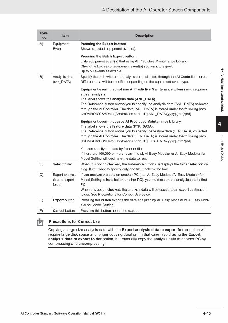
Sym-bol Item Description
(A) EquipmentEvent
Pressing the Export button:Shows selected equipment event(s).
Pressing the Batch Export button:Lists equipment event(s) that using AI Predictive Maintenance Library.Check the box(es) of equipment event(s) you want to export.Up to 50 events selectable.
(B) Analysis data(xxx_DATA)
Specify the path where the analysis data collected through the AI Controller stored.Different data will be specified depending on the equipment event type.
Equipment event that not use AI Predictive Maintenance Library and requiresa user analysisThe label shows the analysis data (ANL_DATA).The Reference button allows you to specify the analysis data (ANL_DATA) collectedthrough the AI Controller. The data (ANL_DATA) is stored under the following path:C:\OMRON\CSVData\[Controller’s serial ID]\ANL_DATA\[yyyy]\[mm]\[dd]
Equipment event that uses AI Predictive Maintenance LibraryThe label shows the feature data (FTR_DATA).The Reference button allows you to specify the feature data (FTR_DATA) collectedthrough the AI Controller. The data (FTR_DATA) is stored under the following path:C:\OMRON\CSVData\[Controller’s serial ID]\FTR_DATA\[yyyy]\[mm]\[dd]
You can specify the data by folder or file.If there are 100,000 or more rows in total, AI Easy Modeler or AI Easy Modeler forModel Setting will decimate the data to read.
(C) Select folder When this option checked, the Reference button (B) displays the folder selection di-alog. If you want to specify only one file, uncheck the box.
(D) Export analysisdata to exportfolder
If you analyze the data on another PC (i.e., AI Easy Modeler/AI Easy Modeler forModel Setting is installed on another PC), you must export the analysis data to thatPC.When this option checked, the analysis data will be copied to an export destinationfolder. See Precautions for Correct Use below.
(E) Export button Pressing this button exports the data analyzed by AL Easy Modeler or AI Easy Mod-eler for Model Setting.
(F) Cancel button Pressing this button aborts the export.
Precautions for Correct Use
Copying a large size analysis data with the Export analysis data to export folder option willrequire large disk space and longer copying duration. In that case, avoid using the Exportanalysis data to export folder option, but manually copy the analysis data to another PC bycompressing and uncompressing.
4 Description of the AI Operator Screen Components
4-13AI Controller Standard Software Operation Manual (W611)
4-4 AI M
achine Learning Model
4
4-4-1 Export Dialog
4-5 Setting WebAPI Connection FunctionThis section describes the procedure to set up the WebAPI connection function of an AI Controller.
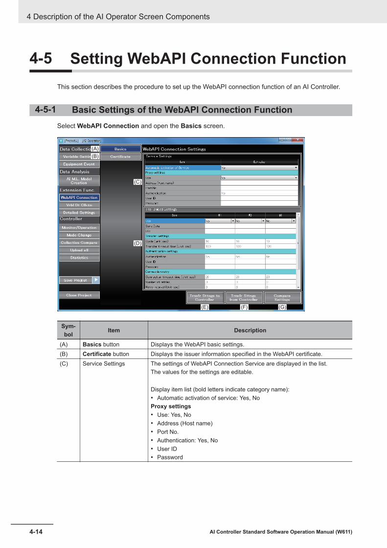
4-5-1 Basic Settings of the WebAPI Connection FunctionSelect WebAPI Connection and open the Basics screen.
(A)
(B)
(C)
(D)
(E) (F) (G)
Sym-bol Item Description
(A) Basics button Displays the WebAPI basic settings.(B) Certificate button Displays the issuer information specified in the WebAPI certificate.(C) Service Settings The settings of WebAPI Connection Service are displayed in the list.
The values for the settings are editable.
Display item list (bold letters indicate category name):• Automatic activation of service: Yes, NoProxy settings• Use: Yes, No• Address (Host name)• Port No.• Authentication: Yes, No• User ID• Password
4 Description of the AI Operator Screen Components
4-14 AI Controller Standard Software Operation Manual (W611)

Sym-bol Item Description
(D) File Upload Settings Displays a list of file upload settings in the Basics settings of the WebAPIconnection.
Display item list (bold letters indicate category name):• Use: Yes, No• Send Data: Analysis Data, Feature Value, Equipment Event Monitoring
ScoreItems selected in another server cannot be selected.
• URLTransfer settings• Cycle (Unit: sec)• Transfer timeout time (Unit: sec)Authentication settings• Authentication: Yes, No• User ID• PasswordConnection retry• Connection timeout time (Unit: sec)• Number of retries• Retry interval (Unit: sec)Security Settings• TSL version: 1.0, 1.1, 1.2
The setting is valid when the transmission URL is HTTPS.• Transfer when the server certificate is expired: Yes, No
The setting is valid when the transmission URL is HTTPS.• OCSP stapling: Yes, No
The setting is valid when the transmission URL is HTTPS.(E) Trnsfr Sttngs to
Controller buttonTransfers the WebAPI connection settings from the computer to the AI Con-troller.
(F) Trnsfr Sttngs fromController button
Transfers the WebAPI connection settings from the AI Controller to the com-puter.
(G) Compare Settings but-ton
Compares the WebAPI connection settings of the computer and the AI Con-troller.
4-5-2 Certificate Settings for WebAPI ConnectionThis section describes the procedure to display a list of root certificates to be imported into the AI Con-troller and how to add and delete certificates.Select WebAPI Connection to open the Certificate screen.
4 Description of the AI Operator Screen Components
4-15AI Controller Standard Software Operation Manual (W611)
4-5 Setting WebA
PI Connection Function
4
4-5-2 Certificate Settings for W
ebAPI Connection

(A)
(B) (C) (D) (E)(F)
Sym-bol Item Description
(A) Trusted Certificated List Displays a list of trusted certificates.(B) Add Trusted
Certificate button
Adds a trusted certificate.Click this button to open the Select File dialog.When you select a file and click the Open button, the selected file is regis-tered to the AI Controller.
(C) Delete Trusted
Certificate button
Deletes a trusted certificate from the AI Controller.When you select a certificate from Trusted Certificate List and click thisbutton, the certificate is deleted.
(D) Get button Transfers a certificate from the AI Controller to the computer.When you select a certificate from Trusted Certificate List and click thisbutton, the Save as dialog opens.Specify a file name and press the Save button to transfer the certificate tothe computer.
(E) Delete All button Deletes all the trusted certificates from the AI Controller.(F) View Details button Displays details of a trusted certificate.
4-5-3 Detailed View of Trusted CertificatesWhen you open the Certificate screen and select View Details, the Certificate detailed view opens.
4 Description of the AI Operator Screen Components
4-16 AI Controller Standard Software Operation Manual (W611)

(B)
(A)
Sym-bol Item Description
(A) Certificate fields Displays details of a certificate.The following items will appear:Version, Serial number, Effective date, Expiration date, Thumbprint, Com-mon name, Organization unit, Organization name, Locality, State or Prov-ince, Country
(B) Close button Closes the Certificate detailed view.
4 Description of the AI Operator Screen Components
4-17AI Controller Standard Software Operation Manual (W611)
4-5 Setting WebA
PI Connection Function
4
4-5-3 Detailed View
of Trusted Certificates

4-6 Collecting Variable DataThis section describes the procedure to collect variables data without having to configure equipmentevents or frame variables.Select Vrbl Dt Cllctn button to open the Variable Data Collection screen.
(A)
(B) (C) (D) (E)
Sym-bol Item Description
(A) List of Registered varia-ble name
Shows the list of variables set on the Variable Settings screen.
(B) Trnsfr Sttngs toController button
Transfers the settings configured on the Variable Data Collection screenfrom the computer to the AI Controller.
(C) Trnsfr Sttngs fromController button
Transfers the settings configured on the Variable Data Collection screenfrom the AI Controller to the computer.
(D) Compare Settings but-ton
Compares the settings on the Variable Data Collection screen againstthose on the AI Controller.
(E) Collection Start/StopOpe. button
Open the Monitor/Operation screen to start or stop the collection of varia-ble data.
4 Description of the AI Operator Screen Components
4-18 AI Controller Standard Software Operation Manual (W611)

4-7 Detailed Settings for Data CollectionYou will configure the export settings for the TSDB function and the settings for transferring CSV filesfrom the AI Controller to the computer.Select Detailed Settings and open the Detailed Settings screen.
(A)
(B)
Sym-bol Item Description
(A) Time Series DB ExportSettings
Shows the settings and values of the TSDB function of the AI Controller.
Setting items:• Number of exported records: If the number of records specified in this set-
ting is stored in TimeSeries, the data will be exported.• Export execution cycle (sec): Specify an export cycle here. Even if the
number of records specified for Number of exported records is not stor-ed in TimeSeries, the data will be exported in the cycle specified in thissetting.
(B) CSV File Transfer PCStorage Settings
Shows the settings of your computer’s storage.
Setting items:• Upper limit of the storage (MB): Specify an upper limit of your computer’s
storage here. Your computer’s storage usage will not exceed the value sethere.
• Operation when the storage limit is exceeded: Specify a behavior whenthe storage limit is exceeded.Options: Delete old files, Stop data collection
4 Description of the AI Operator Screen Components
4-19AI Controller Standard Software Operation Manual (W611)
4-7 Detailed Settings for D
ata Collection
4

4-8 Monitor and OperationThis section describes the procedure to use AI functions of an AI Controller as well as the procedureto monitor the status of the functions.
(A) (B) (C)
(D)
Sym-bol Item Description
(A) TSDB Function button Opens the monitoring screen of the time series database function.(B) F.E/M.L. Function but-
tonOpens the monitoring screen of the Feature Extraction/Machine LearningFunction.
(C) WebAPI Connectionbutton
Opens the service status monitoring screen of the WebAPI connection func-tion.
(D) Status Bar When the Monitor/Operation screen is displayed, the following items alsoappear in addition to the standard display items.• Connection status: Connected/Disconnected• Mode: Program/Run• Error: Yes/None
l Time-series DB Function Monitor and OperationThis section describes the procedure to use the Time Series Database Function of an AI Controlleras well as the procedure to monitor the status of the function.
4 Description of the AI Operator Screen Components
4-20 AI Controller Standard Software Operation Manual (W611)

(A)
(C)
(E)
(F)
(G)
(D)
(H) ( I )
(B)
Symbol Item DescriptionData Collection Phase
(A) Start/Suspend buttonsfor Data Collection forAnalysis
Starts and stops the following collection of analysis data (ANL_DATA).This will start and stop the sampling and export of the TSDB function aswell as the transfer of CSV files from the AI Controller to your computer.
Extension Functions
(B) Start/Suspend buttonsfor Variable DataCollection
Starts/stops the collection of variable data (RAW_DATA).This will start and stop the sampling and export of the TSDB function aswell as the transfer of CSV files from the AI Controller to your computer.
TimeSeries DB Monitor/Operation
(C) TSDB Service Shows the TSDB service status of the AI Controller.One of the following status will appear:• Idle, Running, Error Stop, Shutdown
Press the Start, Suspend, or Shutdown button to start, stop, or shutdownthe TSDB service.
(D) TimeSeries Shows the creation status and the open state of each TimeSeries.One of the following status will appear for the creation status:• Created, Not createdOne of the following status will appear for the open status:• Open, Close
Press Reconstruct button to reconstruct each TimeSeries.(E) Sampling Shows the sampling status of each TimeSeries.
One of the following status will appear:• Running, Idle
Press the Start, Suspend, or Clear button to start, stop, or clear samplingof each TimeSeries.The feature values (FTR_DATA) and equipment event monitoring scores(AIS_DATA) cannot be controlled by the Start and Suspend buttons.
4 Description of the AI Operator Screen Components
4-21AI Controller Standard Software Operation Manual (W611)
4-8 Monitor and O
peration
4
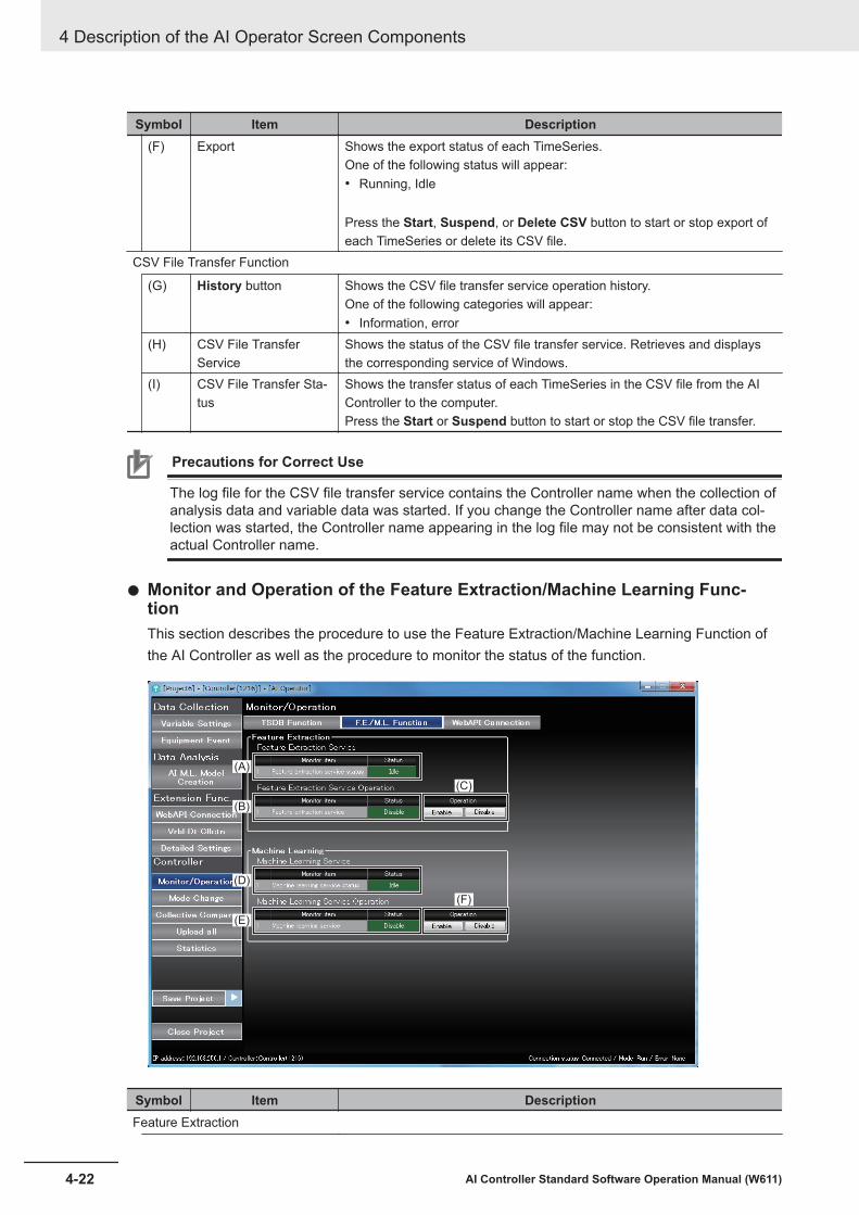
Symbol Item Description(F) Export Shows the export status of each TimeSeries.
One of the following status will appear:• Running, Idle
Press the Start, Suspend, or Delete CSV button to start or stop export ofeach TimeSeries or delete its CSV file.
CSV File Transfer Function
(G) History button Shows the CSV file transfer service operation history.One of the following categories will appear:• Information, error
(H) CSV File TransferService
Shows the status of the CSV file transfer service. Retrieves and displaysthe corresponding service of Windows.
(I) CSV File Transfer Sta-tus
Shows the transfer status of each TimeSeries in the CSV file from the AIController to the computer.Press the Start or Suspend button to start or stop the CSV file transfer.
Precautions for Correct Use
The log file for the CSV file transfer service contains the Controller name when the collection ofanalysis data and variable data was started. If you change the Controller name after data col-lection was started, the Controller name appearing in the log file may not be consistent with theactual Controller name.
l Monitor and Operation of the Feature Extraction/Machine Learning Func-tionThis section describes the procedure to use the Feature Extraction/Machine Learning Function ofthe AI Controller as well as the procedure to monitor the status of the function.
(A)
(B)
(C)
(D)
(E)
(F)
Symbol Item DescriptionFeature Extraction
4 Description of the AI Operator Screen Components
4-22 AI Controller Standard Software Operation Manual (W611)

Symbol Item Description(A) Feature Extraction
Service StatusShows the operating status of the feature extraction service.One of the following status will appear:Running, Idle
(B) Feature ExtractionService Operation
Shows the status of the feature extraction service being enabled or disa-bled.When the system-defined variable Feature Extraction Service Operation(_FE_Enable) is True, the service status is Enable. When it is False, theservice status is Disable.
(C) Enable/Disable but-tons
Enables or disables the feature extraction service.Changes the system-defined variable Feature Extraction Service Opera-tion (_FE_Enable) to True or False.• Enable: Set _FE_Enable to True• Disable: Set _FE_Enable to False
Machine Learning
(D) Machine LearningService Status
Shows the status of the machine learning service.One of the following status will appear:Running, Idle
(E) Machine LearningService Operation
Shows the status of the machine learning service being enabled or disa-bled.When the system-defined variable Machine Learning Service Operation(_MLE_Enable) is True, the service status is Enable. When it is False, theservice status is Disable.
(F) Enable/Disable but-tons
Enables or disables the machine learning service.Changes the system-defined variable Machine Learning Service EnableCommand (_MLE_Enable) to True or False.• Enable: Set _MLE_Enable to True• Disable: Set _MLE_Enable to False
l WebAPI Connection Function Monitor and OperationThis section describes the procedure to use the WebAPI connection function of an AI Controller aswell as the procedure to monitor the status of the function.
4 Description of the AI Operator Screen Components
4-23AI Controller Standard Software Operation Manual (W611)
4-8 Monitor and O
peration
4

(A) (B)
(C) (D) (E) (F)
Symbol Item DescriptionWebAPI Connection Service
(A) Service status Shows the WebAPI connection service status.One of the following status will appear:• Initializing, Idle, Running, Error Stop
(B) Start/Suspend buttons Starts or stops the WebAPI connection service.File Upload
(C) Status Shows the upload status of each file used with the WebAPI connectionfunction.One of the following status will appear:• No transmission record, success, failure, service stopped
(D) Confirm Cnct. buttons Performs a connection test whether a file can be uploaded to the specifiedURL.
(E) Error code Shows the error code in case of a file update failure.(F) Error contents Shows the error contents in case of a file update failure.
4 Description of the AI Operator Screen Components
4-24 AI Controller Standard Software Operation Manual (W611)

4-9 Mode ChangesThis section describes the procedure to change the AI Controller’s operating mode.When you select Mode Change, a message box appears.When the operating mode of the Controller is PROGRAM mode, you can switch it to RUN mode.When it is in RUN mode, you can switch the mode to PROGRAM mode.
Precautions for Safe Use
Before you switch the operating mode of the Controller, ensure that changing the mode will notaffect the system.
4 Description of the AI Operator Screen Components
4-25AI Controller Standard Software Operation Manual (W611)
4-9 Mode C
hanges
4

4-10 Collective ComparisonThis section describes the procedure to compare settings between the computer and the AI Controllerand how to display the differences in a list. When you select Collective Compare, the function is exe-cuted. Then, the Result of collective comparison of settings dialog opens.
(A)
(B)
Sym-bol Item Description
(A) Different settings Compares the settings in the computer and the AI Controller and then dis-plays the settings that are different.
This function compares the following settings.• Data Collection Common Setting• Variable Data (RAW_DATA) Collection Settings• Analysis Data (ANL_DATA) Collection Settings• Feature Value (FTR_DATA) Collection Settings• Equipment Event Monitoring Score (AIS_DATA) Collection Settings• WebAPI Connection Function Setting• Feature Extraction Function Settings• Machine Learning Function Settings• AI Machine Learning Model
(B) Close button Closes the setting comparison screen.
4 Description of the AI Operator Screen Components
4-26 AI Controller Standard Software Operation Manual (W611)

Precautions for Correct Use
When different settings are displayed, execute Partial Transfer to Controller from the screenslisted below.
Different settings Screen to perform partial transfer to ControllerData Collection Common Setting Equipment Event Settings
WebAPI Connection SettingsVariable Data Collection
Variable Data (RAW_DATA) Collection Set-tings
Variable Data Collection
WebAPI Connection Function Setting WebAPI Connection SettingsAnalysis Data (ANL_DATA) Collection Set-tings, Feature value (FTR_DATA) CollectionSettings, Equipment Event Monitoring Score(AIS_DATA) Collection Settings, Feature Ex-traction Function Settings, Machine LearningFunction Settings, or AI Machine LearningModel
Equipment Event Settings
4 Description of the AI Operator Screen Components
4-27AI Controller Standard Software Operation Manual (W611)
4-10 Collective C
omparison
4

4-11 Collective UploadingBy uploading all the information on the AI functions from the AI Controller, you can update data of theproject that is currently open.When you select Upload all and click the Yes button on the message box that appears, the uploadstarts.
Precautions for Correct Use
Once you execute the collective upload, all of the project data is overwritten by the informationuploaded from the AI Controller. Before you execute the collective upload, close the currentproject and create a new project as needed.
4 Description of the AI Operator Screen Components
4-28 AI Controller Standard Software Operation Manual (W611)

4-12 Statistical InformationThis section describes the procedure to show statistical information of the AI Controller’s AI functions.
(A)
(B)
(C)
Sym-bol Item Description
(A) TSDB Function button Displays statistical information of the time series database function.(B) M.L. Function button Displays statistical information of the machine learning function.(C) WebAPI connection
function buttonDisplays statistical information of the WebAPI connection function.
l Statistical Information of the Time-series DB FunctionThis section describes the procedure to show statistical information of the Time Series DatabaseFunction.
4 Description of the AI Operator Screen Components
4-29AI Controller Standard Software Operation Manual (W611)
4-12 Statistical Information
4

(A)
(B)
(C)
Sym-bol Item Description
(A) TimeSeries combo box Allows you to select a TimeSeries in which statistical information you want toretrieve.You can select any of the following:• Analysis data (ANL)• Feature data (FTR)• Equipment event monitoring score data (AIS)• RAW Data (RAW)Press the Get Statistics button to retrieve data.
(B) Type combo box Allows you to select a category of statistical information.You can select any of the following:• TimeSeries information• Sampling processing• Internal buffer• Export processing
4 Description of the AI Operator Screen Components
4-30 AI Controller Standard Software Operation Manual (W611)

Sym-bol Item Description
(C) List of Statistical Infor-mation (TSDB Func-tion)
Displays the retrieved statistical information (TSDB function).The information displayed for each Type is as follows:
TimeSeries information• Storage usage (Byte)• Number of records stored• Time of the latest record• Time of the oldest record
Sampling processing• Number of executed samplings• Sampling execution failure count• Maximum sampling time (ms)• Average sampling time (ms)
Internal buffer• Maximum number of records accumulated in the internal buffer• Number of records discarded by internal buffer• Number of records currently accumulated in the internal buffer
Export processing• Maximum export time (ms)• Average export time (ms)• Export execution count
l Statistical Information of Machine Learning FunctionThis section describes the procedure to show statistical information of the machine learning func-tion.
(A)
(B)
(C)
4 Description of the AI Operator Screen Components
4-31AI Controller Standard Software Operation Manual (W611)
4-12 Statistical Information
4
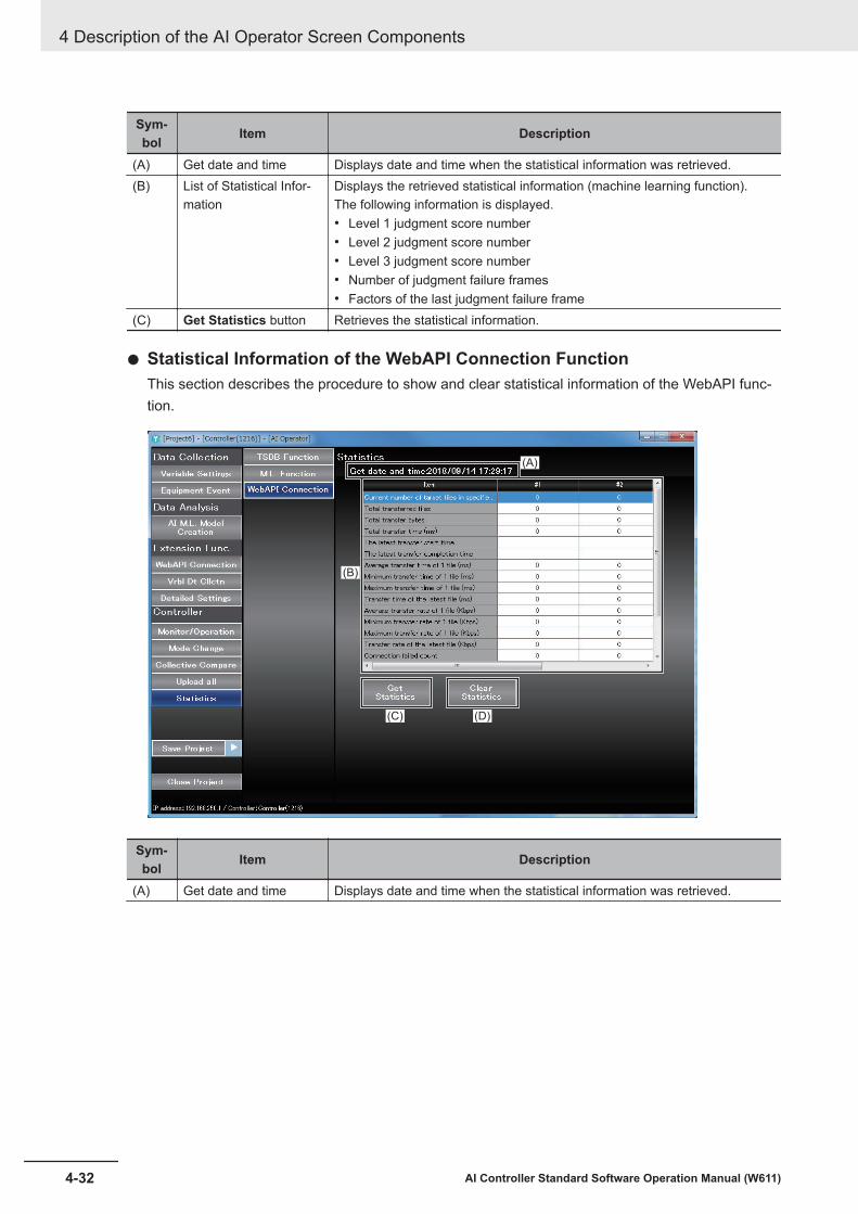
Sym-bol Item Description
(A) Get date and time Displays date and time when the statistical information was retrieved.(B) List of Statistical Infor-
mationDisplays the retrieved statistical information (machine learning function).The following information is displayed.• Level 1 judgment score number• Level 2 judgment score number• Level 3 judgment score number• Number of judgment failure frames• Factors of the last judgment failure frame
(C) Get Statistics button Retrieves the statistical information.
l Statistical Information of the WebAPI Connection FunctionThis section describes the procedure to show and clear statistical information of the WebAPI func-tion.
(A)
(B)
(C) (D)
Sym-bol Item Description
(A) Get date and time Displays date and time when the statistical information was retrieved.
4 Description of the AI Operator Screen Components
4-32 AI Controller Standard Software Operation Manual (W611)

Sym-bol Item Description
(B) List of Statistical Infor-mation
Displays statistical information of each node connected.Statistical information is displayed for each target number #**** (**** is thetarget number) of upload specified in the WebAPI connection settings.
The following information is displayed.• Current number of target files in specified folder• Total transferred files• Total transfer bytes• Total transfer time (ms)• The latest transfer start time• The latest transfer completion time• Average transfer time of 1 file (ms)• Minimum transfer time of 1 file (ms)• Maximum transfer time of 1 file (ms)• Transfer time of the latest file (ms)• Average transfer rate of 1 file (Kbps)• Minimum transfer rate of 1 file (Kbps)• Maximum transfer rate of 1 file (Kbps)• Transfer rate of the latest file (Kbps)• Connection failed count• Transfer failed count• Latest send error error code• Latest send error detection time• Latest send error recovery time
(C) Get Statistics button Retrieves the statistical information.(D) Clear Statistics button Clears the currently displayed statistical information of the connection target.
When you click this button, a confirmation message box appears.
4 Description of the AI Operator Screen Components
4-33AI Controller Standard Software Operation Manual (W611)
4-12 Statistical Information
4

4-13 Authority Verification for AI ControllerOperation
If the operation authority verification is configured for the AI Controller on Sysmac Studio, a passwordentry may be required. In that case, enter a password on a dialog prompting you to enter your pass-word when you connect an AI Controller using the AI Operator.
Precautions for Correct Use
The operation authority verification cannot be configured on the AI Operator. Use Sysmac Stu-dio.Refer to 8-3-1 Operation Authority Verification of the Sysmac Studio Version 1 OperationManual (Cat. No. W504) for details.
4 Description of the AI Operator Screen Components
4-34 AI Controller Standard Software Operation Manual (W611)

5Description of the AI ViewerScreen Components
This section describes names and functions of the AI Viewer screen components.The AI Viewer function allows you to monitor the status of equipment events in the AIController by referencing the AI Controller project that was created on the AI Operator.
5-1 Creating an AI Viewer Project ....................................................................... 5-25-1-1 Starting and Shutting Down the AI Viewer ...................................................... 5-25-1-2 Creating a New AI Viewer Project ................................................................... 5-25-1-3 Opening an AI Viewer Project ......................................................................... 5-3
5-2 Placing Equipment Events ............................................................................ 5-55-2-1 Placing Equipment Events to Designated Locations....................................... 5-65-2-2 Group Settings ................................................................................................ 5-65-2-3 Specifying the Number of Equipment Events on a Single Window ................. 5-7
5-3 Monitor and Operation................................................................................... 5-95-4 Monitoring Equipment Events .................................................................... 5-10
5-4-1 Displaying History.......................................................................................... 5-125-4-2 Displaying the Trend Graph........................................................................... 5-13
5-1AI Controller Standard Software Operation Manual (W611)
5
5-1 Creating an AI Viewer ProjectThis section describes the basic operations of starting and shutting down the AI Viewer, how to createa new project, and how to save a project.
5-1-1 Starting and Shutting Down the AI Viewer
Starting the AI Viewer
1 Use the following procedure to start the AI Viewer.• On Windows, select Start - All Programs - OMRON - AI Controller Standard Software
and then select AI Viewer Settings.The AI Viewer starts up.
Exiting the AI Viewer
1 Click the x button on the right end of the title bar.The AI Viewer will close.
5-1-2 Creating a New AI Viewer ProjectTo utilize data in an AI Controller, you need to create an AI Viewer project on the AI Viewer. This sec-tion describes the procedure to create a new AI Viewer project.Select New Project to open the screen to start creating a new project. Next, specify each item andclick the Create button.
5 Description of the AI Viewer Screen Components
5-2 AI Controller Standard Software Operation Manual (W611)

(A)
(B)
(C)
(D)
Sym-bol Item Description
(A) Create New Project Fill in the following items when you create a new project.• Project name (Text)• Author (Text)• Comment (Text)
(B) Select AI Controllerproject to import
Displays a list of AI Controller projects.*1
Allows you to select an AI Controller project used for the AI Viewer projectby selecting a check box.*2
(C) Project Properties Displays properties of the AI Controller project selected in the selection fieldof AI Controller projects.
(D) Create button Allows you to create a new AI Viewer project from the AI Controller projectselected in the selection field of AI Controller projects.
*1. The list does not show an AI Controller project if it does not contain any equipment event whose learningstatus is completed.
*2. You cannot select more than one AI Controller project from a same Controller.
5-1-3 Opening an AI Viewer ProjectThis section describes the procedure to open an existing AI Viewer project.Select Open Project and open the AI Viewer Project list screen. Next, go to AI Viewer Project Listand select a project. Then, click the Open button.
5 Description of the AI Viewer Screen Components
5-3AI Controller Standard Software Operation Manual (W611)
5-1 Creating an A
I Viewer Project
5
5-1-3 Opening an AI View
er Project

(A)
(B)
(C) (D) (E)
Sym-bol Item Description
(A) AI Viewer Project List Displays a list of created AI Viewer projects.Select an AI Viewer project from the list.
(B) Project Properties Displays the properties of an AI Viewer project selected in AI Viewer projectlist.The following information is displayed.• Author• Created date and time• Last modified• Imported AI Controller project• Comment
(C) Edit button Allows you to edit properties of the selected AI Viewer project.(D) Delete button Deletes the selected AI Viewer project.(E) Open button Opens the selected AI Viewer project.
Additional Information
The AI Viewer project data is stored under C:\OMRON\Application\AIOperator\SettingProjects\UtilProjects\[Project_Name]. To use an AI Viewer project you have created here on anothercomputer, find the folder named the same as the project you want to use and copy the entirefolder.
5 Description of the AI Viewer Screen Components
5-4 AI Controller Standard Software Operation Manual (W611)
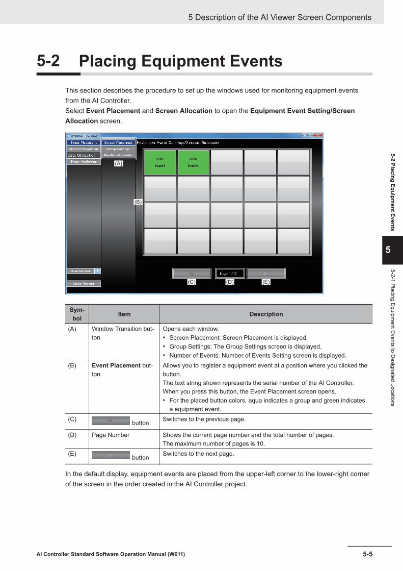
5-2 Placing Equipment EventsThis section describes the procedure to set up the windows used for monitoring equipment eventsfrom the AI Controller.Select Event Placement and Screen Allocation to open the Equipment Event Setting/ScreenAllocation screen.
(A)
(B)
(C) (E)(D)
Sym-bol Item Description
(A) Window Transition but-ton
Opens each window.• Screen Placement: Screen Placement is displayed.• Group Settings: The Group Settings screen is displayed.• Number of Events: Number of Events Setting screen is displayed.
(B) Event Placement but-ton
Allows you to register a equipment event at a position where you clicked thebutton.The text string shown represents the serial number of the AI Controller.When you press this button, the Event Placement screen opens.• For the placed button colors, aqua indicates a group and green indicates
a equipment event.(C) button Switches to the previous page.
(D) Page Number Shows the current page number and the total number of pages.The maximum number of pages is 10.
(E) button Switches to the next page.
In the default display, equipment events are placed from the upper-left corner to the lower-right cornerof the screen in the order created in the AI Controller project.
5 Description of the AI Viewer Screen Components
5-5AI Controller Standard Software Operation Manual (W611)
5-2 Placing Equipment Events
5
5-2-1 Placing Equipment Events to D
esignated Locations
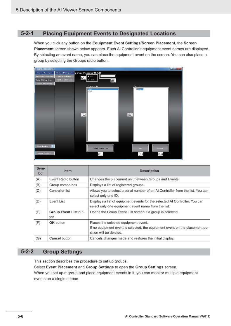
5-2-1 Placing Equipment Events to Designated LocationsWhen you click any button on the Equipment Event Settings/Screen Placement, the ScreenPlacement screen shown below appears. Each AI Controller’s equipment event names are displayed.By selecting an event name, you can place the equipment event on the screen. You can also place agroup by selecting the Groups radio button.
(A)(B)
(C) (D)
(E) (F) (G)
Sym-bol Item Description
(A) Event Radio button Changes the placement unit between Groups and Events.(B) Group combo box Displays a list of registered groups.(C) Controller list Allows you to select a serial number of an AI Controller from the list. You can
select only one ID.(D) Event List Displays a list of equipment events for the selected AI Controller. You can
select only one equipment event name from the list.(E) Group Event List but-
tonOpens the Group Event List screen if a group is selected.
(F) OK button Places the selected equipment event.If no equipment event is selected, the equipment event on the placement po-sition will be deleted.
(G) Cancel button Cancels changes made and restores the initial display.
5-2-2 Group SettingsThis section describes the procedure to set up groups.Select Event Placement and Group Settings to open the Group Settings screen.When you set up a group and place equipment events in it, you can monitor multiple equipmentevents on a single screen.
5 Description of the AI Viewer Screen Components
5-6 AI Controller Standard Software Operation Manual (W611)

(A)
(B) (C)
(D) (E)
Sym-bol Item Description
(A) Group List Displays a list of created groups.• You cannot register a same group name.• You cannot register events from different controllers to a same group.
(B) Add button Adds a group row.
(C) Delete button Deletes a selected group.
(D) Controller list Allows you to select a serial number of an AI Controller from the list. You canselect only one serial number.
(E) Event List Displays a list of equipment events for the selected AI Controller. You canselect only one equipment event name from the list.
5-2-3 Specifying the Number of Equipment Events on a Single Win-dow
This section describes the procedure to specify the number of equipment events displayed on a singlewindow.Select Event Placement and Number of Events to open the Number of Events Setting screen.
5 Description of the AI Viewer Screen Components
5-7AI Controller Standard Software Operation Manual (W611)
5-2 Placing Equipment Events
5
5-2-3 Specifying the Num
ber of Equipment Events on a Single W
indow

(A)
(B)
Sym-bol Item Description
(A) Vertical Allows you to specify the number of equipment events that are verticallyplaced on the screen.Values from 1 to 5 can be specified. The default is set to 4.
(B) Horizontal Allows you to specify the number of equipment events that are horizontallyplaced on the screen.Values from 1 to 8 can be specified. The default is set to 5.
5 Description of the AI Viewer Screen Components
5-8 AI Controller Standard Software Operation Manual (W611)

5-3 Monitor and OperationThis section describes the procedure to monitor the transfer status of feature value files and equip-ment event monitoring score files by using AI Viewer.Select Monitor/Operation to open the Monitor/Operation screen.
(A)
Sym-bol Item Description
(A) Equipment Event Moni-tor
Displays the transfer status of feature values (FTR_DATA), equipment eventmonitoring score (AIS_DATA) for each AI Controller.
The following operations can be performed for "FTR_DATA" and"AIS_DATA".• Starts and stops the transferring CSV files from the AI Controller to the
computer.
5 Description of the AI Viewer Screen Components
5-9AI Controller Standard Software Operation Manual (W611)
5-3 Monitor and O
peration
5

5-4 Monitoring Equipment EventsThis section describes the procedure to monitor the status of equipment events in the AI Controller byusing the AI Viewer.Select Event Monitoring and open the Event Status Monitoring screen.
(A)
(D) (E)(C)
(B)
Sym-bol Item Description
(A) End button Stops the event status monitoring.
5 Description of the AI Viewer Screen Components
5-10 AI Controller Standard Software Operation Manual (W611)

Sym-bol Item Description
(B) Equipment Event Sta-tus button
Displays the status of equipment events and groups.
Text for each button is displayed as follows:• "Controller Name (Serial number)"• "Event name" or "[Group name]"
The equipment event group name is displayed inside the square brackets"[ ]". The square brackets are used for distinguishing groups from equip-ment events.
The status of each equipment event and equipment event group can beidentified by the button color. The meaning of the status and color is as fol-lows:*1 *2
• Dark green: StandbyStatus where data transfer from the AI Controller to the AI Viewer has notbeen executed.
• Light green: NormalStatus of an equipment event for which equipment event monitoring scoreis less than Threshold 1 while data transfer from the AI Controller to the AIViewer has been executed.
• Yellow: Alert Level 1Status of an equipment event for which equipment event monitoring scoreis equal to or greater than Threshold 1 but less than Threshold 2 while da-ta transfer from the AI Controller to the AI Viewer has been executed.
• Red: Alert Level 2Status of an equipment event for which equipment event monitoring scoreis equal to or greater than Threshold 2 while data transfer from the AIController to the AI Viewer has been executed.
• Gray: State where equipment events cannot be monitored.Refer to Cases Where Equipment Events Cannot Be Monitored on page5-12 for information on possible cases.
When you click the button indicating the group status, it opens the groupmonitoring screen displaying the status of equipment events that are regis-tered to the group.When you click the button showing the status of equipment events, it opensthe trend graph screen.
(C) Dt Cllct. Hst. button If an error exists in the CSV file transfer service, the following messages willappear.• Can not connect (FTP) to the controller.• Failed to delete the file in the controller.• No storage space is left.
(D) button If the monitoring target is registered across pages, use the buttons to switchpages.The current page and the total number of pages are displayed betweenthese buttons to switch pages.
(E) Eqpmnt Evnt Hst. but-ton
Displays the history screen of Alert Level 1 and Alert Level 2 errors that oc-curred after starting the AI Viewer.
*1. For equipment event groups, if any of the equipment events in a group contains an warning-level error, thestatus is “Warning”. If it contains no warning but one or more caution exists, the status is “Caution”. If it isfree from warning or caution, the event status is displayed as “Normal”.
*2. Equipment events for which CSV file was not retrieved are displayed in gray.
5 Description of the AI Viewer Screen Components
5-11AI Controller Standard Software Operation Manual (W611)
5-4 Monitoring Equipm
ent Events
5
5-4-1 Displaying H
istory

l Cases Where Equipment Events Cannot Be MonitoredYou cannot monitor equipment events while the system is in unmonitored state or in a monitoringscore judgment failure state.The Equipment Event Status button is displayed in gray.Equipment events cannot be monitored in the following cases.
Status Possible cases CorrectionUnmonitored state Waiting for the operation of the monitored
mechanism to stabilize.-
Execution of AI FB was interrupted.*1 -
Monitoring score judg-ment failure state
Input parameters for AI FB are out of range.*1 Check the input parameters.
Inputs for monitor target are incorrect. Check the allocation of inputvariables and wirings.
The specified sub-frame does not exist in theframe.
Check the input timing of theinput variables.
An error occurred in a monitored motion controlinstruction or the instruction was aborted.
Check the input values of themotion control instruction andits execution results.
*1. For details on corrections for the AI FB, refer to Sysmac Library AI Predictive Maintenance LibraryUser’s Manual (Cat. No. W610).
5-4-1 Displaying HistoryThis section describes the procedure to display the history of Alert Level 1 and Alert level 2 errors thatoccurred in the monitored equipment events after starting the Event Status Monitoring screen.On the Event Status Monitoring screen, press the Eqpmnt Evnt Hst. button. The history is dis-played.
(A)
(B)
Sym-bol Item Description
(A) History Displays the history of Alert Level 1 and Alert Level 2 errors after starting theEvent Status Monitoring screen.The errors are displayed in chronological order in an AI Controller.*1*2
5 Description of the AI Viewer Screen Components
5-12 AI Controller Standard Software Operation Manual (W611)

Sym-bol Item Description
(B) Return button The Event Status Monitoring screen opens again.*1. Even if a Alert Level 1 error is already recorded, the error will be recorded again if the status changes to
Alert Level 2.*2. Up to 1000 entries are recorded in the history. After exceeding the limit, entries are deleted from the oldest
one.
5-4-2 Displaying the Trend GraphAfter starting the Event Status Monitoring screen, open the past Event Status Monitoring screen ofthe monitored equipment event and press the Equipment Event Status button for the target equip-ment event. The trend graph appears.
(A)
(B)
(H)
( J)
(I)
(C)
(D)(E) (F) (G)
Sym-bol Item Description
(A) Return button Exits the trend graph screen.(B) Target Date Allows you to select a date for the equipment event monitoring score to dis-
play.(C) Time Selection combo
boxAllows you to select an equipment event monitoring score to display on thetrend graph.You can select an equipment event monitoring score from the ones that existfor the target date.You can also specify the time directly by clicking the time icon. In this case,the equipment event monitoring score that is closest to the specified time willbe selected.
(D) Legend Displays the legend of each plot in the graph of the equipment event moni-toring score.
(E) Graph Operation Modebutton
Allows you to work with the graph by using the mouse.
(F) Zoom In/Out Mode but-ton
Allows you to increase or decrease the size of the graph.
(G) Graph Reset Restores the initial display of the graph.
5 Description of the AI Viewer Screen Components
5-13AI Controller Standard Software Operation Manual (W611)
5-4 Monitoring Equipm
ent Events
5
5-4-2 Displaying the Trend G
raph

Sym-bol Item Description
(H) Trend Graph Display Displays the feature value’s trend graph for each equipment event monitor-ing score and variable.• Equipment Event Monitoring Score:
The horizontal scale is dependent on the number of frames for the CSVfile(s) specified in the time selection combo box.
• Feature data: The vertical scale automatically changes according to thevalues.The horizontal scale is dependent on the number of frames for the CSVfile(s) specified in the time selection combo box.
(I) Variable Name Selec-tion combo box
Allows you to select a variable here, and the feature value of the variable isdisplayed on the trend graph.
(J) Variable data graph When you press any point (frame) on the equipment event monitoringscore’s trend graph, a graph of the variable data in the corresponding framewill appear.*1
*1. It is displayed when the analysis data (ANL_DATA) is collected. If it is not collected, a message stating NotFound Data appears.
5 Description of the AI Viewer Screen Components
5-14 AI Controller Standard Software Operation Manual (W611)
6Using AI Predictive MaintenanceLibrary
This chapter explains functions that are necessary to use the AI Predictive Mainte-nance Library.When you use the AI Predictive Maintenance Library - one of the Sysmac libraries, itmakes it easier for you to monitor the status of equipment events on the AI Controller.This chapter describes operations to use the AI Predictive Maintenance Library.Refer to the Sysmac Library AI Predictive Maintenance Library User’s Manual (Cat.No.W610) for details on the AI Predictive Maintenance Library.
6-1 Installing AI Predictive Maintenance Library............................................... 6-26-2 Registering License for AI Predictive Maintenance Library ...................... 6-46-3 Registering Equipment Events by Using the AI Predictive Mainte-
nance Library to the AI Operator ................................................................... 6-56-4 Checking the Versions of the AI Predictive Maintenance Library ............. 6-7
6-1AI Controller Standard Software Operation Manual (W611)
6
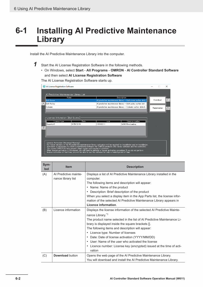
6-1 Installing AI Predictive MaintenanceLibrary
Install the AI Predictive Maintenance Library into the computer.
1 Start the AI License Registration Software in the following methods.• On Windows, select Start - All Programs - OMRON - AI Controller Standard Software
and then select AI License Registration SoftwareThe AI License Registration Software starts up.
(A)
(B)
(C)
(D)
Sym-bol Item Description
(A) AI Predictive mainte-nance library list
Displays a list of AI Predictive Maintenance Library installed in thecomputer.The following items and description will appear:• Name: Name of the product• Description: Brief description of the productWhen you select a display item in the App Parts list, the license infor-mation of the selected AI Predictive Maintenance Library appears inLicence information.
(B) Licence information Displays the license information of the selected AI Predictive Mainte-nance Library.*1
The product name selected in the list of AI Predictive Maintenance Li-brary is displayed inside the square brackets [].The following items and description will appear:• Licence type: Number of licenses• Date: Date of license activation (YYYY/MM/DD)• User: Name of the user who activated the license• Licence number: License key (encrypted) issued at the time of acti-
vation(C) Download button Opens the web page of the AI Predictive Maintenance Library.
You will download and install the AI Predictive Maintenance Library.
6 Using AI Predictive Maintenance Library
6-2 AI Controller Standard Software Operation Manual (W611)
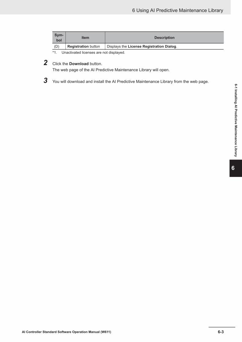
Sym-bol Item Description
(D) Registration button Displays the License Registration Dialog.*1. Unactivated licenses are not displayed.
2 Click the Download button.The web page of the AI Predictive Maintenance Library will open.
3 You will download and install the AI Predictive Maintenance Library from the web page.
6 Using AI Predictive Maintenance Library
6-3AI Controller Standard Software Operation Manual (W611)
6-1 Installing AI Predictive M
aintenance Library
6

6-2 Registering License for AI PredictiveMaintenance Library
You need to register your license of the installed AI Predictive Maintenance Library.
1 On the AI Predictive Maintenance Library List of the AI License Registration Software, se-lect an AI Predictive Maintenance Library for which license you want to register.
2 Select the Registration button, and then enter the license number printed on the license sheetthat you purchased.The registered license information is displayed on the License Registration screen.
Precautions for Correct Use
Please purchase the licenses of AI Predictive Maintenance Library for the number of the mech-anism that you use.
6 Using AI Predictive Maintenance Library
6-4 AI Controller Standard Software Operation Manual (W611)
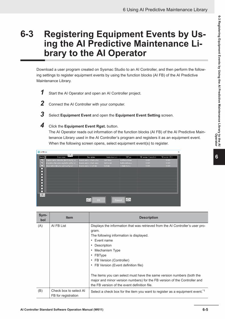
6-3 Registering Equipment Events by Us-ing the AI Predictive Maintenance Li-brary to the AI Operator
Download a user program created on Sysmac Studio to an AI Controller, and then perform the follow-ing settings to register equipment events by using the function blocks (AI FB) of the AI PredictiveMaintenance Library.
1 Start the AI Operator and open an AI Controller project.
2 Connect the AI Controller with your computer.
3 Select Equipment Event and open the Equipment Event Setting screen.
4 Click the Equipment Event Rgst. button.The AI Operator reads out information of the function blocks (AI FB) of the AI Predictive Main-tenance Library used in the AI Controller’s program and registers it as an equipment event.When the following screen opens, select equipment event(s) to register.
(A)
(B)
(C) (D)
Sym-bol Item Description
(A) AI FB List Displays the information that was retrieved from the AI Controller’s user pro-gram.The following information is displayed.• Event name• Description• Mechanism Type• FBType• FB Version (Controller)• FB Version (Event definition file)
The items you can select must have the same version numbers (both themajor and minor version numbers) for the FB version of the Controller andthe FB version of the event definition file.
(B) Check box to select AIFB for registration
Select a check box for the item you want to register as a equipment event.*1
6 Using AI Predictive Maintenance Library
6-5AI Controller Standard Software Operation Manual (W611)
6-3 Registering Equipm
ent Events by Using the A
I Predictive Maintenance Library to the A
IO
perator
6

Sym-bol Item Description
(C) OK button Adds the selected item as the equipment event.(D) Cancel button Cancels the registration of the equipment event.
*1. The number of check boxes you can select is “Maximum number of registered events” >= “Number ofevents currently registered + Number of AI FB items selected”.
Precautions for Correct Use
When you read the function block information again for the AI Controller to which equipmentevent is already registered after reading the function block (AI FB) information, the functionblock (AI FB) information that was already registered will be loaded again and displayed in thelist. To prevent this, you can choose not to register the function block as an equipment event orregister the function block again after deleting the equipment event that was already registered.
6 Using AI Predictive Maintenance Library
6-6 AI Controller Standard Software Operation Manual (W611)

6-4 Checking the Versions of the AI Pre-dictive Maintenance Library
When the AI Operator reads out information of the function blocks (AI FB) used in the AI Controller’suser program, the AI Operator checks the version of the AI Predictive Maintenance Library installed inyour computer against the version of the AI FB on the Controller side. If they are different versions, thedialog shown below will appear.
You can either install the same version of the function blocks (AI FB) of the AI Predictive MaintenanceLibraries used in the AI Controller to your computer or replace the function blocks (AI FB) of the AIPredictive Maintenance Libraries used in the AI Controller to those corresponding to the version of theAI Predictive Maintenance Library that is installed in your computer.
(A)
(B)
Sym-bol Item Description
(A) AI FB List Displays the information that was retrieved from the event definition file.The following information is displayed.• AI FB• FBType• FB Instance• FB Version (Controller)• FB Version (Event definition file)
(B) OK button Closes the dialog.
6 Using AI Predictive Maintenance Library
6-7AI Controller Standard Software Operation Manual (W611)
6-4 Checking the Versions of the A
I Predictive Maintenance Library
6

6 Using AI Predictive Maintenance Library
6-8 AI Controller Standard Software Operation Manual (W611)

AAppendices
A-1 Errors and Troubleshooting......................................................................... A-2
A-1AI Controller Standard Software Operation Manual (W611)
A

A-1 Errors and TroubleshootingThis section describes the error messages displayed during the AI Controller operations performed onthe AI Operator and the AI Viewer, along with the troubleshooting methods. For the AI Controller er-rors, refer to the NX/NY-series Artificial Intelligence Machine Automation Controller User’s Manual(Cat. No. W594).
List of Error Messages during AI Controller Operations by AI Oper-ator
Message Cause CorrectionFailed to connect to the controller. Cable disconnected Check the cable connection and try again.
No access privilege Forcibly release the access privilege onSysmac Studio and try again.
Write protected Release the write protect for the CPU Uniton Sysmac Studio and try again.
Downloading by an-other tool is in prog-ress
Try again after a while. (Wait for the down-load by another tool to complete)
The operation can-not be executed be-cause the Controlleris in the error state.
Check the AI Controller error, reset the er-ror and try again.
A communications error occurred./ Com-munications were disconnected.
An error occurred inthe communicationmessage.
Check the cable connection and try again.Try again after a while. (Wait for the down-load by another tool to complete)
No response fromthe Controller wasreceived.
Check the cable connection and try again.Cycle the power supply to the AI Controller.
List of Error Messages during Data Collection with an AI ControllerConnected
Message Cause CorrectionCan not connect (FTP) to the controller. FTP connection er-
rorCheck to see if the FTP connection set-tings of the project are consistent with theController’s system settings.
Cable disconnected Check the cable connection and try again.The operation can-not be executed be-cause the Controlleris in the error state.
Check the AI Controller error, reset the er-ror and try again.
Failed to acquire the file in the controller./Failed to delete the file in the controller.
The operation can-not be executed be-cause the Controlleris in the error state.
Check the AI Controller error, reset the er-ror and try again.
Failed to read the data collection serviceconfiguration file.
See the messagefor details.
Pause the data collection and start again.
Appendices
A-2 AI Controller Standard Software Operation Manual (W611)

Message Cause CorrectionNo storage space is left. The storage media
in the computerdoes not haveenough free space.
Increase free space by deleting unneces-sary files, and so on.
Appendices
A-3AI Controller Standard Software Operation Manual (W611)
A-1 Errors and Troubleshooting
A

Appendices
A-4 AI Controller Standard Software Operation Manual (W611)
IIndex
I-1AI Controller Standard Software Operation Manual (W611)
I

IndexA
AI Controller.................................................... 4-14, 5-10, 6-5AI Controller Project................................................... 4-2, 4-4AI Controllers.....................................................................2-5AI License Registration Software...................................... 6-2AI Operator.................................................. 1-2, 1-3, 3-3, 4-2AI Predictive Maintenance Library.....................................6-2AI Viewer......................................................1-2, 1-3, 3-4, 5-2AI Viewer project................................................................5-3AI Viewer Project............................................................... 5-2AIS_DATA.................................................................4-26, 5-9Alert Level 1............................................................5-11, 5-12Alert Level 2.....................................................................5-12Alert Level.2.....................................................................5-11Analysis Data......................................................... 4-15, 5-14ANL_DATA.......................................................................4-26
C
Collective Compare........................................................... 3-3Collective Comparison.....................................................4-26Collective Upload...............................................................3-3Connection status............................................................4-20Controller........................................................................... 3-3Controller Name........................................................4-4, 5-11Controller Operation Authority......................................... 4-34CSV file(s)....................................................................... 5-14
D
Data Analysis.....................................................................1-2Data Collection.................................................................. 1-2Data Collection for Analysis.............................................4-21Data Utilization.................................................................. 1-2Detailed Settings...................................................... 3-3, 4-19
E
Equipment Event............................................................... 1-2Equipment Event Monitoring........................................... 5-10equipment event monitoring score.................................... 5-9Equipment Event Monitoring Score................................. 4-15Equipment Event Placement............................................. 5-5equipment events.............................................................. 4-9Event Status Monitoring................................ 5-10, 5-12, 5-13Export.............................................................................. 4-22Extension Function............................................................ 3-3
F
F.E. Output Frame Var. (ANY_INT)..................................4-10Feature Extraction Service.............................................. 4-23Feature Value.................................................................. 4-15feature values.................................................................... 5-9File Upload Settings........................................................ 4-15
Frame Variable.................................................................. 4-9FTP Password................................................................... 4-3FTR_DATA............................................................... 4-26, 5-9Function Block................................................................... 6-5function blocks...................................................................6-7
G
Group.................................................................................5-6Groups............................................................................. 5-11
H
History.................................................................... 4-22, 5-12
L
Label variables................................................................ 4-10License Registration.......................................................... 6-4licenses..............................................................................1-3log file.............................................................................. 4-22
M
M.L. Output Frame Var. (ANY_INT).................................4-10Machine learning function................................................4-31Machine Learning Function............................................. 4-22Machine Learning Service............................................... 4-23Mode Changes................................................................ 4-25
N
.NET Framework............................................................... 1-4
O
operating mode................................................................4-25Operating mode...............................................................4-20
P
Page Switching.........................................................5-5, 5-11password......................................................................... 4-34Password................................................................4-14, 4-15
R
RAW_DATA..................................................................... 4-26
S
Sampling..........................................................................4-21Serial ID.............................................................................4-4Serial number...................................................................5-11Statistical Information...................................................... 4-29Statistics............................................................................ 3-3Sub-frame Variable............................................................4-9
Index
I-2 AI Controller Standard Software Operation Manual (W611)

Sysmac Studio.................................................. 4-7, 4-34, 6-5
T
Time Series Database Function............................. 4-20, 4-29Time Series DB Export Settings...................................... 4-19TimeSeries............................................................. 4-21, 4-30Trend Graph.................................................................... 5-13Trusted Certificate........................................................... 4-16TSDB Service.................................................................. 4-21
U
Upload all.........................................................................4-28
V
Variable Data Collection........................................... 3-3, 4-21Variable Setting..................................................................4-6
W
WebAPI Connection function...........................................4-23WebAPI Connection Function..........................................4-32WebAPI Connection Service........................................... 4-14Windows 10................................................................1-4, 2-4Windows 7..................................................................1-4, 2-4
Index
I-3AI Controller Standard Software Operation Manual (W611)
I

Index
I-4 AI Controller Standard Software Operation Manual (W611)


Authorized Distributor:
In the interest of product improvement, specifications are subject to change without notice.
Cat. No. W611-E1-03 0421
© OMRON Corporation 2018-2021 All Rights Reserved.
OMRON Corporation Industrial Automation Company
OMRON ELECTRONICS LLC2895 Greenspoint Parkway, Suite 200 Hoffman Estates, IL 60169 U.S.A.Tel: (1) 847-843-7900/Fax: (1) 847-843-7787
Regional Headquarters
OMRON EUROPE B.V.Wegalaan 67-69, 2132 JD HoofddorpThe NetherlandsTel: (31)2356-81-300/Fax: (31)2356-81-388
Contact: www.ia.omron.com
Kyoto, JAPAN
OMRON ASIA PACIFIC PTE. LTD.No. 438A Alexandra Road # 05-05/08 (Lobby 2), Alexandra Technopark, Singapore 119967Tel: (65) 6835-3011/Fax: (65) 6835-2711
OMRON (CHINA) CO., LTD.Room 2211, Bank of China Tower, 200 Yin Cheng Zhong Road, PuDong New Area, Shanghai, 200120, ChinaTel: (86) 21-5037-2222/Fax: (86) 21-5037-2200