automatic time for cd players
TRANSCRIPT
8/14/2019 Automatic Time for CD Players
http://slidepdf.com/reader/full/automatic-time-for-cd-players 1/1
CIRCUIT
IDEAS
90 D E C E M B E R 2 0 0 5 • E L E C T RON I C S F OR Y OU W W W . E F Y M A G . C O M
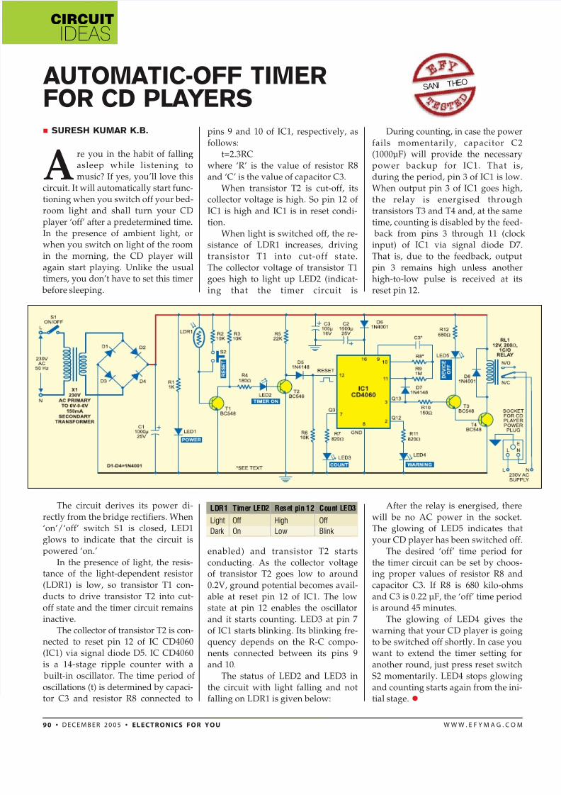
LDR1 Timer LED2 Reset pin 12 Count LED3
Light Off High Off
Dark On Low Blink
Are you in the habit of fallingasleep while listening to
music? If yes, you’ll love this
circuit. It will automatically start func-tioning when you switch off your bed-
room light and shall turn your CD
player ‘off’ after a predetermined time.In the presence of ambient light, orwhen you switch on light of the room
in the morning, the CD player will
again start playing. Unlike the usual
timers, you don’t have to set this timer before sleeping.
The circuit derives its power di-
rectly from the bridge rectifiers. When‘on’/‘off’ switch S1 is closed, LED1
glows to indicate that the circuit is
powered ‘on.’
In the presence of light, the resis-tance of the light-dependent resistor
(LDR1) is low, so transistor T1 con-
ducts to drive transistor T2 into cut-
off state and the timer circuit remainsinactive.
The collector of transistor T2 is con-nected to reset pin 12 of IC CD4060(IC1) via signal diode D5. IC CD4060
is a 14-stage ripple counter with a
built-in oscillator. The time period of
oscillations (t) is determined by capaci-
tor C3 and resistor R8 connected to
SURESH KUMAR K.B.
AUTOMATIC-OFF TIMERFOR CD PLAYERS
SA NI T HE O
pins 9 and 10 of IC1, respectively, as
follows:t=2.3RC
where ‘R’ is the value of resistor R8and ‘C’ is the value of capacitor C3.
When transistor T2 is cut-off, itscollector voltage is high. So pin 12 of
IC1 is high and IC1 is in reset condi-
tion.When light is switched off, the re-
sistance of LDR1 increases, driving
transistor T1 into cut-off state.
The collector voltage of transistor T1
goes high to light up LED2 (indicat-ing that the timer circuit is
enabled) and transistor T2 starts
conducting. As the collector voltageof transistor T2 goes low to around
0.2V, ground potential becomes avail-
able at reset pin 12 of IC1. The lowstate at pin 12 enables the oscillator
and it starts counting. LED3 at pin 7
of IC1 starts blinking. Its blinking fre-quency depends on the R-C compo-nents connected between its pins 9
and 10.
The status of LED2 and LED3 in
the circuit with light falling and not
falling on LDR1 is given below:
During counting, in case the power
fails momentarily, capacitor C2(1000µF) will provide the necessary
power backup for IC1. That is,during the period, pin 3 of IC1 is low.
When output pin 3 of IC1 goes high,the relay is energised through
transistors T3 and T4 and, at the same
time, counting is disabled by the feed- back from pins 3 through 11 (clockinput) of IC1 via signal diode D7.
That is, due to the feedback, output
pin 3 remains high unless another
high-to-low pulse is received at itsreset pin 12.
After the relay is energised, there
will be no AC power in the socket.The glowing of LED5 indicates that
your CD player has been switched off.
The desired ‘off’ time period for
the timer circuit can be set by choos-ing proper values of resistor R8 and
capacitor C3. If R8 is 680 kilo-ohms
and C3 is 0.22 µF, the ‘off’ time periodis around 45 minutes.
The glowing of LED4 gives the
warning that your CD player is goingto be switched off shortly. In case youwant to extend the timer setting for
another round, just press reset switch
S2 momentarily. LED4 stops glowing
and counting starts again from the ini-
tial stage.