automatic rolling garage door opener - bnd.com.au · maximum door size and door load 3000mm high...
TRANSCRIPT

Instruction Manual
Controll-A-Door® 5Automatic Rolling Garage Door Opener
N1134
Instruction Manual©Copyright 2001B&D Australia
Page 1
ISO9002
Controll-A-Door™
A U T O M A T I C G A R A G E D O O R O P E N E R
POWER
CODE SET
LIMIT SET
WARNING: Cover not to be removed except by
authorised technician

START BY READING THESE IMPORTANT SAFETY RULES
These safety alert symbols mean Caution – a personal safety or property damageinstruction. Read these instructions carefully.This Automatic Garage Door Opener is designed and tested to offer safe service provided it isinstalled and operated in strict accordance with the following safety rules.Failure to comply with the following instructions may result in serious personal injuryor property damage.
Caution: If your garage has no service entrance door, an emergency access device can be installed. This accessory allows manual operation of the garage door from outside in case of power failure.
This opener should be installed inaccordance with relevant AustralianStandards.
Do not allow children to play with doorcontrols (AS3350).
Keep remote controls away from children(AS3350).
Watch the moving door and keep peopleaway until the door is completely openedor closed (AS3350).
Activate the opener only when the door isin full view, free of obstructions and withthe opener properly adjusted.
Keep garage door balanced. Sticking orbinding doors must be repaired. Garagedoors, door springs, brackets and theirhardware are under extreme tension and cancause serious personal injury. Do notattempt any adjustment. Do not use ifrepair or adjustment is needed.Call for professional garage door service.
Install optional door control button in alocation where the garage door is visible,but out of the reach of children at a heightof at least 1.5m (AS3350).
Do not wear rings, watches or looseclothing while installing or servicing a garage door opener.
This opener is not suitable for commercial,industrial or common entry applications.
To avoid serious personal injury fromentanglement, remove all unnecessaryropes or chains and disable anyequipment such as locks which are notneeded for powered operation (AS3350).
Installation and wiring must be in compliancewith your local building and electrical codes.Connect the power cord only to properlyearthed mains. If an extension lead is used,make sure it is a 3 core lead and approved to5 amp capacity.
If the supply card is damaged, it must bereplaced by the manufacturer or its serviceagent or a similar qualified person in order toavoid hazard.
Do not use the force adjustments tocompensate for a binding or stickinggarage door. Excessive force will interferewith the proper operation of the SafetyReverse System or damage the garage door.
Disconnect electric power to the garagedoor opener before removing covers.
When using optional auto close mode, a B&Dsafety infrared beam must be fitted correctlyand tested for operation at regular intervals.Extreme caution is recommended when usingauto close mode. All safety rules must befollowed.
This opener is a 240 volt appliance andmust be installed in a dry position that isprotected from the weather.
The opener is not intended for use by youngchildren or infirm persons without supervision.
A properly earthed, 3 pin, 240 volt power supply is required.
WARNING! A portable power generator is not recommended. The opener may appear tomalfunction due to spikes, surges and fluctuations in the generated voltage.
Page 2 ©Copyright 2001B&D Australia

CONTENTS
Safety Rules ....................................................................................................................p. 2Contents ..........................................................................................................................p. 3About your B&D Controll-A-Door 5 Unit ......................................................................p. 4Specifications ................................................................................................................p. 4Accessories ....................................................................................................................p. 5
Section 1 RequirementsDoor Operation....................................................................................................p. 6Position................................................................................................................p. 6Power Supply ......................................................................................................p. 6Sideroom..............................................................................................................p. 6What you may need ............................................................................................p. 7
Section 2 General Arrangement......................................................................................................p. 7Items Supplied in the carton..............................................................................p. 7
Section 3 Installation ProceduresPreparation ........................................................................................................p. 8Fit Weight Bar......................................................................................................p. 8Pin the Door Curtain ..........................................................................................p. 9Fit the Opener......................................................................................................p. 9Program The Opener ........................................................................................p. 10Setting Dip Switches ........................................................................................p. 10Door Travel Limit Setting ................................................................................p. 11Remote Control Transmitter Code Setting ....................................................p. 12Setting Remote Control Transmitter Dip Switch Codes ..............................p. 12To Erase Programmed Codes..........................................................................p. 12Safety System ..................................................................................................p. 12Testing the Safety System ..............................................................................p. 13
Section 4 Fitting Accessory ItemsFitting Wired Accessories................................................................................p. 14
Section 5 How To Operate ......................................................................................................p. 14Remote Control Transmiter..............................................................................p. 15Inbuilt Locking Facility ....................................................................................p. 15Manual Operation..............................................................................................p. 16Power Failure ....................................................................................................p. 16Safety Infra Red Beam Option ........................................................................p. 16Auto Close Option ............................................................................................p. 16Remote Control Transmitter Battery ..............................................................p. 16Changing a Light Globe ..................................................................................p. 17Service Call ......................................................................................................p. 17Maintenance ......................................................................................................p. 17
Section 6 Diagnostic Codes ......................................................................................................p. 19Section 7 Save a Service Call ......................................................................................................p. 21Section 8 Warranty ......................................................................................................p. 22
Should you have any queries or require assistance with your Controll-A-Door opener, contact your local B&DDealer or contact the B&D office in your capital city. See back page of this handbook for contact details.
IMPORTANT SAFETY INSTRUCTIONSWARNING - It is vital for the safety of persons to follow all instructions.
SAVE THESE INSTRUCTIONS
©Copyright 2001B&D Australia
Page 3
AS3350

ABOUT YOUR B&D CONTROLL-A-DOOR® 5 OPENER
Thank you for choosing B&D’s Controll-A-Door® 5. This automatic garage door opener has been designed anddeveloped in Australia by B&D Automatic Access Systems - an Australian Owned company - to suit local conditions.
The technically advanced construction of this B&D Controll-A-Door® 5 opener ensures you enjoy the followingbenefits:
• 5 year full parts and labour warranty on motor, electronics and mechanical components of the opener(Conditions Apply).
• Your own private security code with 3.486 billion available codes, meaning only you can open your garage door.Allows you to electronically program your security code at the touch of a button.
• Standard 3 channel remote control transmitter allows you to operate an adjoining garage door or entry gateif automated
• Automatic safety reverse should the door be obstructed while closing.
• Courtesy light automatically switches on for approximately 41/2 minutes when operating the door.
• Emergency release handle for manual operation of the door in the event of a power failure.
• Automatic resetting of all codes and limits after a power failure.
• No need to manually lock your garage door, as Controll-A-Door® 5 ‘positively’ locks the door when closed.
• Adjustable safety reversing settings to compensate for changes in door characteristics.
• Auto closing option can be programmed to close the door approximately 30 seconds after the door has opened.
N.B. Safety Infra Red Beams must be installed if this option is chosen
• Flashing LED’s to easily identify operational problems or service requirements.
• Compatible with a wide range of B & D Controll-A-Door® Accessories.
SPECIFICATIONSMaximum Door Size and Door Load 3000mm high Residential Rolling Garage Door or
2400mm high Wind Lock Residential Rolling Garage Door that doesnot exceed 200N (20kgs) bottom rail load
Supply Voltage 220 – 240 volts AC – 50 Hz only
Current Maximum 3.5 Amps
Lamp One 25 watt, Pilot Lamp,on when door starts, off approx. 4 1/2 minutes later
Limit Adjustment Electronic
Remote Control Transmitter Frequency 433.92 MHz
Rated Load 250N AS3350
Page 4 ©Copyright 2001B&D Australia

ACCESSORIES
B&D has a range of additional accessories for your added convenience and security.
• Safety Infra Red Beams. Gives additional protection if the door is closing onto your property or person. Simplybreaking the beam “stops” the door! Must be fitted if autoclosing feature is operational - Part No 62153.
• Keyring remote control transmitter. Ideal for personal use when entry into the house may be via the garage –Part No 62162.
• Entry Keypad. Key in your own 4 digit PIN (Personal Identification Number). Allows you to open the garagewithout taking a key or remote control remote control transmitter with you. Ideal for children or when out jogging(no need to hide a key!) – Part No 62173.
• Remote control transmitter Wall Button. Allows you to operate the opener within 10 metres of the door. Ideal formounting inside the house – Part No 62163.
• Remote Control Transmitter 3 Channel 433MHz. Get a spare remote control transmitter for your second car ormount it inside the house for convenient operation of your garage door – Part No 62170.
• Combo Access Kit. Keyswitch function will open the door without a remote control transmitter. Can be used tomanually disengage the opener, recommended when the garage door is the only access to the garage –Part No 59009.
Also available for your convenience is the B&D Controll-A-Gate® automatic gate opener. With models to suit swingand slide gates for residential applications. Most of your Accessories are compatible with Controll-A-Gate®.
Contact your authorised B&D dealer for installation of these accessory items.
©Copyright 2001B&D Australia
Page 5
SAFETY INFRA-R
ED BEAM
SAFETY INFRA-RED BEAMEMERGENCYSTOP
CONTROLLIMIT
ACTUATOR
ACTUATOR

SECTION 1 - REQUIREMENTS
IMPORTANT SAFETY INSTRUCTIONS FOR INSTALLATION
WARNING - INCORRECT INSTALLATION CAN LEAD TO SEVERE INJURY.
FOLLOW ALL INSTALLATION INSTRUCTIONS.
DOOR OPERATION
The door must be in good operating condition and the maximum effort to move the door up or down, from stationary,should not exceed 200 Newton’s (20kg force) at the bottom rail. The door may need to be serviced to meet thisrequirement - refer to door manufacturers servicing instructions
Before installing the opener, check that the door is in good mechanical condition and correctlybalanced and that it opens and closes properly. AS3350
Note: The fitting of an opener to doors with removable mullions is not recommended.
POSITION
It is recommended that the opener be installed on the right hand side of the door, however the opener can beinstalled on either the right hand or left hand side of the door (viewed from inside the garage looking out - left is left).The opener must be mounted in a dry position that is protected from the weather. The B&D Controll-A-Door 5® is notdesigned for external use. Moisture or corrosion may damage the opener and this is not covered by the Warranty. Donot allow water, or other liquids, to enter the opener or remote control transmitter.
POWER SUPPLY
A properly earthed, 3 pin, 240 volt power supply is required.
WARNING! A portable power generator is not recommended. The opener may appearto malfunction due to spikes, surges and fluctuations in the generated voltage.
SIDEROOM
Dimension A = 75mm maximum. This is the distance from the door drum to theedge of the door curtain/door guide. If dimension A is greater than 75mm, a ring gearadaptor (Part No 59585) will be required.
Dimension B = 120mm minimum to 135mm maximum. This is the distance fromthe door drum to the inside of the door bracket.
Dimension C = 165mm minimum. This is the distance from the door drum to thegarage wall.
Note:
1 The door bracket may have to be relocated to line up with the slots in the mounting bracket of the opener (theopener may be mounted onto the axle - see Fit The Opener for special instructions.
2 The chassis must not be cut down to reduce sideroom - the warranty is invalidated if this occurs.3 These dimensions assume the opener will be fitted while the door is on the floor. If the door is already installed an
additional 150mm clearance is required to slide the opener over the axle.
Page 6 ©Copyright 2001B&D Australia
AS3350

Instruction Manual
Controll-A-Door® 5Automatic Rolling Garage Door Opener
N1134
Instruction Manual©Copyright 2001B&D Australia
Page 1
ISO9002
Controll-A-Door™
A U T O M A T I C G A R A G E D O O R O P E N E R
POWER
CODE SET
LIMIT SET
WARNING: Cover not to be removed except by
authorised technician
WHAT YOU MAY NEED TO DO THE JOB
❐ Suitable door support (eg. a ladder)❐ Phillips screwdriver❐ Suitable sockets and handle with a 150mm extension❐ 450mm pipe wrench (Stillson) or similar❐ Adjustable wrench or spanner set❐ Marking pencil❐ Tape measure❐ Drill❐ 4.5mm drill bit for mounting weight bar❐ 3.2mm drill bit for pinning door curtain❐ length of rope
Items supplied in the carton:
1. Instruction Manual2. Powerhead3. Weightbar4. Hardware package containing:
a. Qty 1 Axle to bracket clampb. Qty 2 nut whiz 5/16 UNCc. Qty 1 Bolt U 5/16 x 2 1/2d. Qty 2 Screw M4 x 50e. Qty 2 Nut M4 Hexf. Qty 2 5/32 shakeproof washerg. Qty 2 3/16x1/2 flat washersh. Qty 2 locking bar coversi. Qty 2 washer 6.4x20.6x1.2 to pin
the door curtainj. Qty 2 Screw 10x32 Self Tappingk. Qty 1 Cable Clipl. Qty 1 Transmitter with visor clip
SECTION 2 – GENERAL ARRANGEMENT
1. Instruction Manual
4. Hardware Bag
2. Powerhead
3. Weightbar
©Copyright 2001B&D Australia
Page 7
a. QTY 1
h.
b.
c.
d.
f.
e.
g.
l. QTY 1k.
j.
i.

SECTION 3 – INSTALLATION PROCEDURES
The following is the preferred method of installing the opener
Step 1: Preparation
a. Check the door operation.i. The door must be smooth to operate by hand.ii. Operating force on the bottom rail must not exceed 200 Newton’s (20kg) force.iii. Adjust the guides if they are tight or replace if they are twisted.iv. Clean the guides if there is any oil or wax present.
b. Install locking bar covers if there are locking bar holes in the guides
Note: DO NOT lock your door with the locking bars after installing your opener. Locksshould be disabled (recommend the use of tie wire or cable ties). This will notaffect the ability of your door to lock as the opener has an inbuilt locking facility.
c. Choose the end where you will install the opener and ensure there is sufficient sideroom. (Refer to sideroomrequirement).
d. Warning labels supplied with this opener should be fitted as appropriate.
Step 2: FIT WEIGHT BAR
The weight bar must be fitted to the bottom-centre of the door as follows:
If the door has a handle:• Remove the door handle, and• Fit the weight bar and refit the handle using the new fasteners provided
If the door does not have a handle:• measure in from both sides of the door to find the
centre of the door at the bottom• place the weight bar at this point (there is a
centerline marked on the weight bar) and mark thetwo positions where the fasteners will go.
• Drill the two 4.5mm holes in the door and fit theweight bar using the new fasteners provided.
• Cut excess screw length if protruding past door rail.
Check that the door is balanced and smooth to operate. If it is not then the door may require servicing (refer to doormanufacturers instructions).
The door is held under significant tension. Adjustments should only be carriedout by experienced persons, as this function can be dangerous if not performedunder strict safety procedures.
Page 8 ©Copyright 2001B&D Australia
WEIGHT BAR
SCREW FOR HANDLE
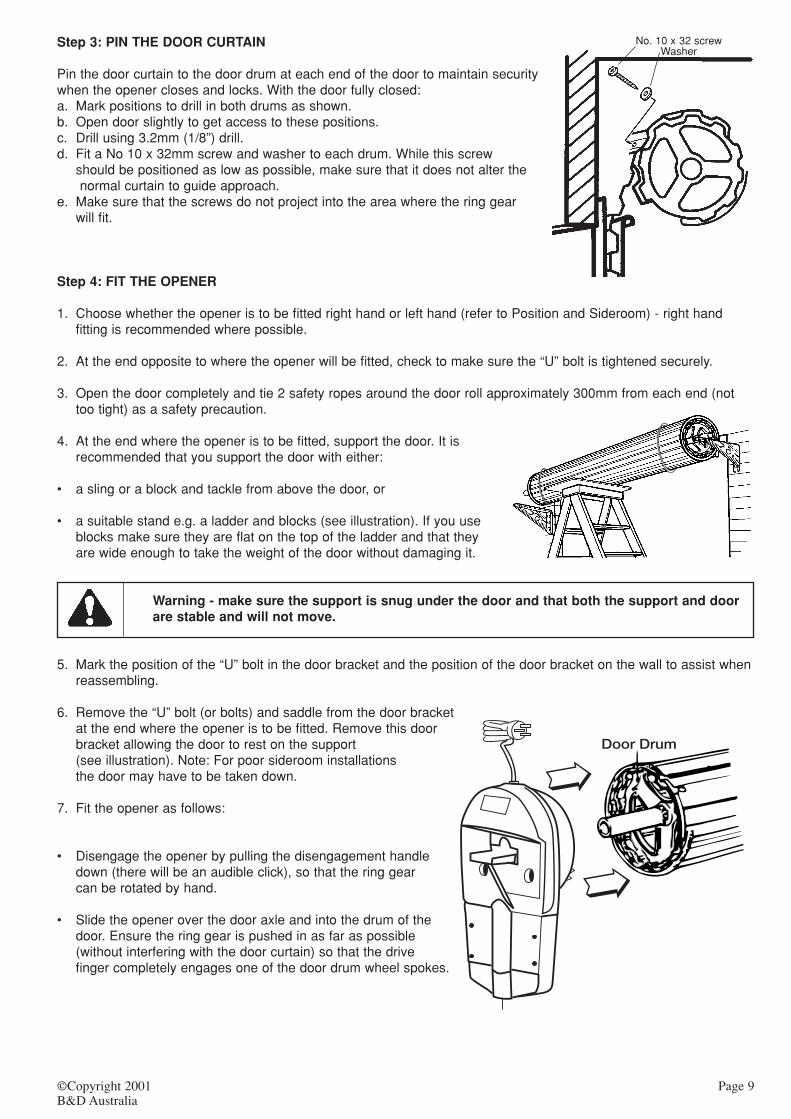
Step 3: PIN THE DOOR CURTAIN
Pin the door curtain to the door drum at each end of the door to maintain securitywhen the opener closes and locks. With the door fully closed:a. Mark positions to drill in both drums as shown.b. Open door slightly to get access to these positions.c. Drill using 3.2mm (1/8”) drill.d. Fit a No 10 x 32mm screw and washer to each drum. While this screw
should be positioned as low as possible, make sure that it does not alter thenormal curtain to guide approach.
e. Make sure that the screws do not project into the area where the ring gearwill fit.
Step 4: FIT THE OPENER
1. Choose whether the opener is to be fitted right hand or left hand (refer to Position and Sideroom) - right handfitting is recommended where possible.
2. At the end opposite to where the opener will be fitted, check to make sure the “U” bolt is tightened securely.
3. Open the door completely and tie 2 safety ropes around the door roll approximately 300mm from each end (nottoo tight) as a safety precaution.
4. At the end where the opener is to be fitted, support the door. It isrecommended that you support the door with either:
• a sling or a block and tackle from above the door, or
• a suitable stand e.g. a ladder and blocks (see illustration). If you useblocks make sure they are flat on the top of the ladder and that theyare wide enough to take the weight of the door without damaging it.
Warning - make sure the support is snug under the door and that both the support and doorare stable and will not move.
5. Mark the position of the “U” bolt in the door bracket and the position of the door bracket on the wall to assist whenreassembling.
6. Remove the “U” bolt (or bolts) and saddle from the door bracketat the end where the opener is to be fitted. Remove this doorbracket allowing the door to rest on the support(see illustration). Note: For poor sideroom installationsthe door may have to be taken down.
7. Fit the opener as follows:
• Disengage the opener by pulling the disengagement handledown (there will be an audible click), so that the ring gearcan be rotated by hand.
• Slide the opener over the door axle and into the drum of thedoor. Ensure the ring gear is pushed in as far as possible(without interfering with the door curtain) so that the drivefinger completely engages one of the door drum wheel spokes.
No. 10 x 32 screwWasher
©Copyright 2001B&D Australia
Page 9
➯
➯

8. Re-attach the door bracket using your reference marks as a guide and tighten the bolts. Ensure that the slots inthe mounting bracket of the opener align with the slots in the door bracket - the door bracket may have to berelocated.
Note: If the bracket cannot be relocated, the opener may be fitted onto the axle as follows:• For Series 1 style doors - you will need to use two Series 1 style, 5/16” U bolts and saddles (one set supplied) to
attach the operator to the axle, or• For Series 2 style doors - you will need to use the Series 2 style, 3/8” U bolt and cast saddle (not supplied) to
attach the operator to the axle.
9. Using your reference marks as a guide:• For Series 1 style doors - fit the new U bolt and saddle with the 2 nuts supplied and tighten firmly, or• For Series 2 style doors - reuse the existing bolt and saddle arrangement. Note: the Series 2 style cast saddle
will need to have 1mm ground off both sides to fit into the operator mounting bracket.
10. Adjust the door position (if necessary) on the brackets so that the door feeds smoothly into the guides. Makesure that the center of the door doesn’t hit the lintel and that the curtain is not pushed forward hard into the guide.
11. Remove the support and safety ropes.
If the manual release is more than 1.8 metres from floor level when the opener isinstalled, extend the manual release handle to a height less than 1.8 metres.
12. Connect the power cord to a suitable power point - do not switch on. Secure the cord away from any movingobject (e.g. the door roll) with the cable clip supplied.
13. Pull the door up and down to make sure it runs freely - make sure the ring gear is still disengaged.
Step 5: PROGRAM THE OPENER
The opener needs to have the dipswitches, force settings, door travel limits and remote control transmitter codesprogrammed before it is fully operational. The following method of programming is recommended. Remove the 2screws retaining the light cover, the light cover can hang on the disengagement handle. (the screws are captive andshould remain in the light cover).
Step 6: Setting DipSwitches.
There are 4 dipswitches located at the base of the opener that need to be set before power is turned on, as follows:
Page 10 ©Copyright 2001B&D Australia
5 4 3 2 1
S1
S2
AS3350
SS

• Switch 1: R or L. This switch selects which side of the door the opener is to be installed on -L for Left Hand, Rfor Right Hand. Changing the Left-Right switch will cause all previously programmed limits to be erased. Thepower to the opener must be turned off then on again whenever this switch is updated.
• Switch 2: S1 or S2. This switch changes the sensitivity of the obstruction sensing system. If the door is a smallSeries 1 door in good condition set the switch to S1, for larger doors like Series 2 doors set the switch to S2.
• Switch 3: AC - OFF. This switch enables the autoclose feature. An IR Beam must be fitted and enabled for thisfeature to work. When autoclose is selected the door will close automatically 30 seconds after opening. The doorwill attempt to close up to 4 times (for 2 minutes) if repeatedly prevented by obstructions.
• Switch 4: IR - OFF. This switch enables a remote infra red beam accessory to be fitted. When “On” an IR Beamaccessory must be fitted and functional. If an IR Beam is not operating then the door, once opened, cannot beclosed. The relays will click twice when the operate button is pressed to indicate this condition. When an IRBeam is selected and functioning correctly the door will cease closing (or refuse to close) when the beam isobstructed. When off (normal operation) any IR Beam accessory will be ignored and the autoclose featuredisabled (even if selected).
Step 7: Door Travel Limit Setting.
Limits must be programmed for the desired range of movement of the door as follows: i. Turn on the power to the opener, the CODE SET and LIMIT SET lights will flash rapidly for a few seconds whilst
the opener goes through a diagnostic self-test, then the POWER LED will illuminate.ii. The operator should still be disengaged, if not, disengage the opener by pulling down the handle.
Use caution when operating the manual release with the door open since it may fall rapidly due to weak or broken springs, or an imbalanced door AS3350
Caution: Do not disengage the opener to manual operation with children/persons or any objects including motor vehicles within the doorway.
iii. Manually move the door to a position half way between theopen and closed positions.
iv. Press the LIMIT SET button until the Limit Set LEDilluminates (approx. 3 seconds).
v. Move the door to the desired lower limit and press the LIMITSET button to accept this bottom limit. The Limit Set LED willnow be flashing.
vi. Move the door to the desired upper limit and press the LIMITSET button to accept this limit. The flashing LED will go out.
vii. Re-engage the opener by pulling down on the handle. viii. Hold the light cover in place and press the operate button to
ensure that the door closes and opens properly.
NB: Limit setting can also be set using the operate button on the opener. Start with the door engaged in the half wayposition. Press the LIMIT SET button until the Limit Set LED illuminates (approx. 3 seconds). Press the Operatebutton until the door is in the bottom setting position and press LIMIT SET. Press the Operate button for the door tomove to the top setting, press LIMIT SET. The limits are now set.
Step 8: Remote Control Transmitter Code Setting.
The receiver needs to learn the codes of any remote control device that will be used with the operator. The receiverhas storage for 14 memory codes and can store:
• Up to 12 remote control transmitters. After 12 codes have been stored, any additional code stored will cause theoldest code to be erased.
• One dip-switch remote control transmitter code, and • One entry keypad code.
Note: Programming a different dip-switch code or entry keypad will automatically erase any previously programmed code.
Controll-A-Door™
A U T O M A T I C G A R A G E D O O R O P E N E R
POWER
CODE SET
LIMIT SET
WARNING: Cover not to be removed except byauthorised technician
LimitSetLED
LimitSetButton
©Copyright 2001B&D Australia
Page 11

All remote control transmitter codes are learned using one of the following procedures:
Procedure 1:• Ensure the Power LED is ON.• Press and hold the remote control transmitter button to be
programmed. For an entry keypad the desired code shouldbe typed (a minimum of four numbers or letters) and theENTER button held down.
• Press and release the Code Set button.• The Code Set LED will start flashing to indicate that the code
has been learnt, but the door will not move.• Release the button on the remote control transmitter.
Procedure 2:• Ensure the Power LED is ON.• Press the Code Set button on the opener, the Code Set LED will illuminate.• Press and hold the remote control transmitter button to be programmed. For an entry keypad the desired code
should be typed (a minimum of four numbers or letters) and the ENTER button held down.• The Code Set LED will start flashing to indicate that the code has been learnt, but the door will not move.• Release the button on the remote control transmitter.
Note:1. If you release the remote control transmitter button before the CODE SET LED flashes, the opener has not
learned the code.2. Additional remote control transmitters can be programmed by repeating the above steps.
Step 9: SETTING REMOTE CONTROL TRANSMITTERDIPSWITCH CODES.
Some remote control transmitters have a dip-switch facility.Generally, dipswitches are used when several persons areoperating the same opener. The dip-switches must be setto matching positions in all remotes used to activate theopener.• Remove the battery cover.• Set switches in all remote controls to matching positions
(+, -, 0). Use a pen or screwdriver.• Replace covers and program this code, using the methods
in procedure 1 or 2.
Install any fixed control (eg keypad, key switch or wall button) within sight of the door but away from moving parts and at a height of at least 1.5 metres.
Step 10: TO ERASE PROGRAMMED CODES.
If the Code Set button is pressed and held on for 6 seconds, the LED will blink rapidly for one second to indicate thatall programmed codes have been erased.
Step 11: SAFETY SYSTEM.
It is extremely important that the safety system is set upcorrectly and that the system be tested/adjusted on a regularbasis. The force should be sufficient to move the door duringnormal operation but not excessively high to prevent the safetysystem activating in the case of a collision. The opening andclosing force adjustments are the same for left-hand and right-hand installation. The system should be set up as follows:
Page 12 ©Copyright 2001B&D Australia
Controll-A-Door™
A U T O M A T I C G A R A G E D O O R O P E N E R
POWER
CODE SET
LIMIT SET
WARNING: Cover not to be removed except byauthorised technician
CodeSetLED
Code Set Button
S1
S2
AS3350

Closing Forcea. The door should be in the open position with power on. b. Set the closing force adjuster initially to the minimum position.c. Press the remote control transmitter (or whilst holding the light cover in place, press the operate button) to start
the door moving down. If the door reverses whilst closing (or does not move at all), increase the closing forceadjuster (turn the closing force adjuster clockwise) in small increments until the door closes properly(Alternatively, for large doors you may set the closing force adjuster to the mid position and whilst the door ismoving down, decrease the closing force (slowly turning the closing adjuster anti clockwise) until the doorreverses.Note: You may need to repeat steps a to c.
d. Once you have completed step c., increase (turn clockwise) the closing force adjuster by 1/8th of a turn e. Operate the door to ensure that it closes without reversing.
Opening Forcef. Set the opening force adjuster to the mid position.g. With the door in the closed position, operate the opener to open the door. Whilst the door is opening, decrease
the opening force (turn the opening force adjuster anti-clockwise) until the door halts (the Code Set and Limit SetLED’s will flash to indicate a collision error).
h. Clear the flashing LED’s by holding the light cover in place and press the operate button, the flashing LED’s willstop flashing.Note: - you may need to repeat steps g and h.
i. Increase the opening force adjuster (turn the opening force adjuster clockwise) by 1/4 of a turn.j. Operate the door to ensure that it opens without halting.
Testk. Test the Safety Reversing System and make any adjustments as necessary.l. Refit the light cover and press the operate button to ensure the door opens and closes properly.
Permanently fix the label warning against entrapment and manual operation in aprominent place or near any fixed controls.After installation, ensure that the mechanism is properly adjusted and that the openerreverses when the door contacts a 40mm high object placed on the floor under thegarage door.
Step 12: TESTING THE SAFETY SYSTEM
The operation of the Safety System must be tested whenever there has been any change in settings, or adjustmentto the door and tested monthly during the operational life of the opener. To test the safety system the followingprocedure should be used.
Door Closing Test• Ensure that the door is open. • Place a 40mm obstacle laid flat on the floor under the garage door.• Operate the door in the down direction, the door must reverse on hitting the obstruction.• If the door fails to reverse, or stops on the obstruction, the down force will have to be decreased.• Remove the obstacle and run the opener through a complete travel cycle.
Door Opening Test• Ensure that the door is closed. • Operate the opener to open the door. • While the door is opening (approximately 1 metre off the floor) hold the bottom edge of the door with your hand.
When a moderate downward force (100 Newton’s/10kg) is exerted, the door should halt. • This will cause the LED’s to start flashing to indicate an error. • Clear the collision error by pressing the operate button, the LED’s will stop flashing. • If the door fails to halt the up force will have to be decreased (see above).
Check to make sure the door opens and closes properly.
The safety system is designed to prevent entrapment or serious injury. It reliesupon physical contact with objects in the path of the door. The safety system alone may not prevent cosmetic damage to motor vehicles or property.
©Copyright 2001B&D Australia
Page 13
AS3350
SECTION 4 – FITTING ACCESSORY ITEM
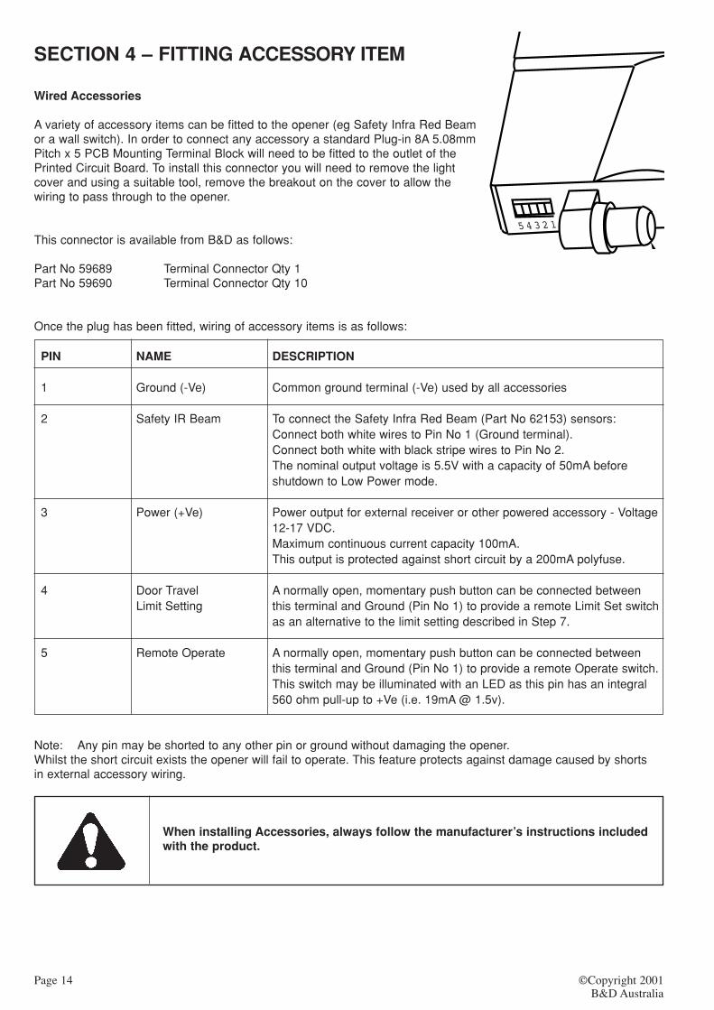
Wired Accessories
A variety of accessory items can be fitted to the opener (eg Safety Infra Red Beamor a wall switch). In order to connect any accessory a standard Plug-in 8A 5.08mmPitch x 5 PCB Mounting Terminal Block will need to be fitted to the outlet of thePrinted Circuit Board. To install this connector you will need to remove the lightcover and using a suitable tool, remove the breakout on the cover to allow thewiring to pass through to the opener.
This connector is available from B&D as follows:
Part No 59689 Terminal Connector Qty 1Part No 59690 Terminal Connector Qty 10
Once the plug has been fitted, wiring of accessory items is as follows:
PIN NAME DESCRIPTION
1 Ground (-Ve) Common ground terminal (-Ve) used by all accessories
2 Safety IR Beam To connect the Safety Infra Red Beam (Part No 62153) sensors: Connect both white wires to Pin No 1 (Ground terminal). Connect both white with black stripe wires to Pin No 2. The nominal output voltage is 5.5V with a capacity of 50mA before shutdown to Low Power mode.
3 Power (+Ve) Power output for external receiver or other powered accessory - Voltage12-17 VDC.Maximum continuous current capacity 100mA.This output is protected against short circuit by a 200mA polyfuse.
4 Door Travel A normally open, momentary push button can be connected betweenLimit Setting this terminal and Ground (Pin No 1) to provide a remote Limit Set switch
as an alternative to the limit setting described in Step 7.
5 Remote Operate A normally open, momentary push button can be connected betweenthis terminal and Ground (Pin No 1) to provide a remote Operate switch.This switch may be illuminated with an LED as this pin has an integral560 ohm pull-up to +Ve (i.e. 19mA @ 1.5v).
Note: Any pin may be shorted to any other pin or ground without damaging the opener. Whilst the short circuit exists the opener will fail to operate. This feature protects against damage caused by shorts in external accessory wiring.
When installing Accessories, always follow the manufacturer’s instructions included with the product.
Page 14 ©Copyright 2001B&D Australia
5 4 3 2 1

SECTION 5 - HOW TO OPERATE
For maximum efficiency of your opener, your garage door must be in good operating condition. A regular service ofthe door by an authorised B&D dealer is recommended.
• Activate the opener only when the door is in full view, free of obstructions and withthe opener properly adjusted. No one should enter or leave the garage while thedoor is in motion. Do not allow children to play near the door.
• This opener is a 240 volt appliance and there are no user serviceable parts insidethis opener
Remote Control Transmitter 3 Channel
To use the remote control transmitter:
• Press the programmed button of the remote control transmitter until your door begins to move (usually 2seconds) to open or close the door. Make sure you can see the door when you use the remote controltransmitter.
If you are in a vehicle you should aim the remote control transmitter throughyour windscreen. You may attach your remote control transmitter to yourvisor with the clip provided, it should be secured so that when the remotecontrol transmitter is operated it is transmitting through the vehiclewindscreen.
• Check that the door is fully closed before you drive away.
• If you press the remote control transmitter whilst the door is moving:
i. Downwards – the door will stop and then reverse to the open position.
ii. Upwards – the door will stop, with the next press of the remote control transmitter the door will movedownwards.
Note: Once the door is moving, the operating distance of the remote control transmitter is significantlyless than when the door is stationary.
Additional remote control transmitters may be purchased at any time.
Operate Button.
Incorporated in the light cover is an operate button. Pressing this button will operate the door, the same as the remote control transmitter as described above.
If the LEDs are flashing a diagnostic code, pressing this button will reset theopener and stop the flashing LEDs.
Inbuilt Locking Facility
DO NOT lock your door with the locking bars when your opener is engaged.This opener has an inbuilt locking facility. With the opener engaged your doorwill be locked whether the power is on or off.
©Copyright 2001B&D Australia
Page 15
Operate Button
Controll-A-Door™
A U T O M A T I C G A R A G E D O O R O P E N E R
POWER
CODE SET
LIMIT SET
WARNING: Cover not to be removed except byauthorised technicianPower
LED
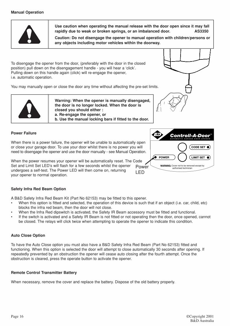
Manual Operation
Use caution when operating the manual release with the door open since it may fallrapidly due to weak or broken springs, or an imbalanced door. AS3350
Caution: Do not disengage the opener to manual operation with children/persons or any objects including motor vehicles within the doorway.
To disengage the opener from the door, (preferably with the door in the closed position) pull down on the disengagement handle - you will hear a ‘click’.Pulling down on this handle again (click) will re-engage the opener,i.e. automatic operation.
You may manually open or close the door any time without affecting the pre-set limits.
Warning: When the opener is manually disengaged,the door is no longer locked. When the door is closed you should either :a. Re-engage the opener, orb. Use the manual locking bars if fitted to the door.
Power Failure
When there is a power failure, the opener will be unable to automatically openor close your garage door. To use your door whilst there is no power you willneed to disengage the opener and use the door manually - see Manual Operation.
When the power resumes your opener will be automatically reset. The CodeSet and Limit Set LED’s will flash for a few seconds whilst the openerundergoes a self-test. The Power LED will then come on, returningyour opener to normal operation.
Safety Infra Red Beam Option
A B&D Safety Infra Red Beam Kit (Part No 62153) may be fitted to this opener. • When this option is fitted and selected, the operation of this device is such that if an object (i.e. car, child, etc)
blocks the infra red beam, then the door will not close.• When the Infra Red dipswitch is activated, the Safety IR Beam accessory must be fitted and functional.• If the switch is activated and a Safety IR Beam is not fitted or not operating then the door, once opened, cannot
be closed. The relays will click twice when attempting to operate the opener to indicate this condition.
Auto Close Option
To have the Auto Close option you must also have a B&D Safety Infra Red Beam (Part No 62153) fitted andfunctioning. When this option is selected the door will attempt to close automatically 30 seconds after opening. Ifrepeatedly prevented by an obstruction the opener will cease auto closing after the fourth attempt. Once theobstruction is cleared, press the operate button to activate the opener.
Remote Control Transmitter Battery
When necessary, remove the cover and replace the battery. Dispose of the old battery properly.
Page 16 ©Copyright 2001B&D Australia

5 4 3 2 1
©Copyright 2001B&D Australia
Page 17
Changing the Light Globe
Your opener uses a 240 Volt, 25 Watt, standard bayonet Pilot Light globe. If you should need to change a light globe,proceed as follows:
1. Close the garage door to gain better access.2. Turn off the power at the power point.3. Remove the light cover.4. Remove the light globe and replace with a suitable new globe.5. Refit the light cover.6. Turn the power on, and7. Press the operate button to ensure the opener is functioning correctly.
Service Call
If the opener needs service please call the dealer who installed the opener or your local B&D dealer.
Before calling for service you should have the following information to assist in providing the correctservice:
1. Has anything happened since the door was last operating OK e.g. storm, a jolt to the door etc?2. How easy is the door to open/close?3. What model is the opener?4. Who installed the opener?5. When was it installed?6. Are there any error codes?
Maintenance
Whilst your opener does not require any periodic maintenance, the door that it is fitted to does. To ensure long andtrouble free life of your opener the following is recommended:
Monthly
• Disengage the opener and manually operate the door. • The door must be smooth to operate by hand, and• Operating force on the bottom rail should not exceed 200 Newtons (20kg) force.• Each month check that the opener reverses when the door contacts a 40mm high object placed on the floor.
Adjust if necessary and recheck since an incorrect adjustment may present a hazard (AS3350). Refer to Step 12.
If the door does not operate smoothly, call B&D or your nearest B&D Authorized Dealer.
Yearly
• We suggest that you contact B&D or your nearest B&D Authorized Dealer to perform an annual door service.
Warning: Failure to maintain your garage door may void your warranty.
Frequently examine the installation, in particular cables, springs and mountings, for signs of wear, damage or imbalance. Do not use if repair or adjustment is needed since a fault in the installation or an incorrectly balanced door may cause injury.
AS3350Adjustments should only be carried out by experienced persons, as this function canbe dangerous if not performed under strict safety procedures.
Page 18 ©Copyright 2001B&D Australia
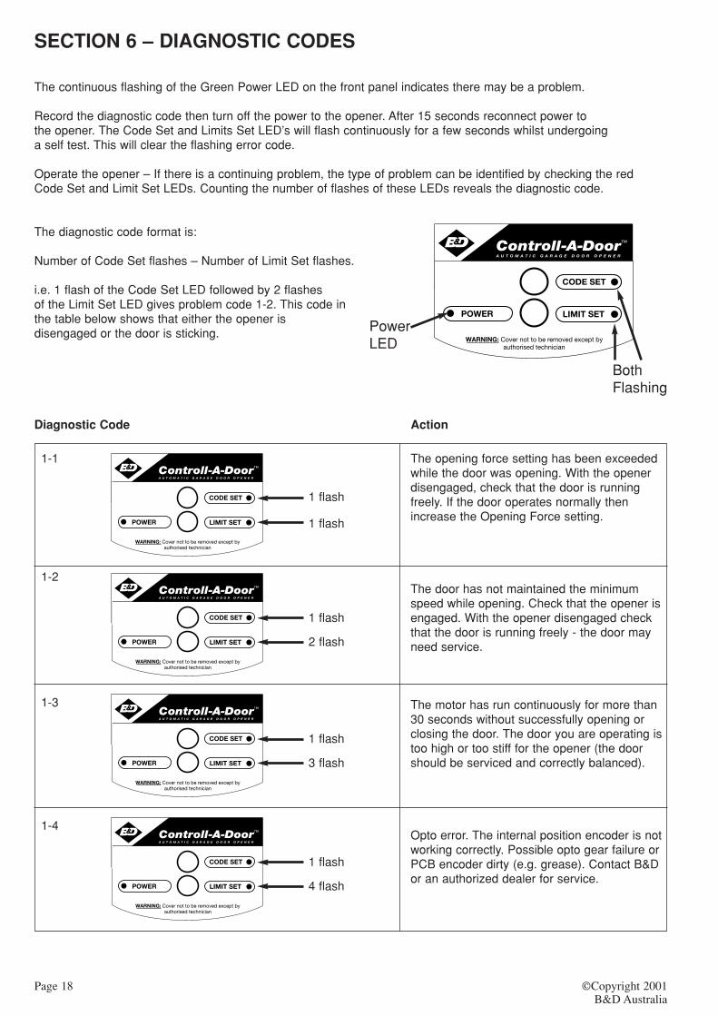
SECTION 6 – DIAGNOSTIC CODES
The continuous flashing of the Green Power LED on the front panel indicates there may be a problem.
Record the diagnostic code then turn off the power to the opener. After 15 seconds reconnect power to the opener. The Code Set and Limits Set LED’s will flash continuously for a few seconds whilst undergoing a self test. This will clear the flashing error code.
Operate the opener – If there is a continuing problem, the type of problem can be identified by checking the redCode Set and Limit Set LEDs. Counting the number of flashes of these LEDs reveals the diagnostic code.
The diagnostic code format is:
Number of Code Set flashes – Number of Limit Set flashes.
i.e. 1 flash of the Code Set LED followed by 2 flashesof the Limit Set LED gives problem code 1-2. This code inthe table below shows that either the opener isdisengaged or the door is sticking.
Diagnostic Code Action
1-1
1-2
1-3
1-4
The opening force setting has been exceededwhile the door was opening. With the openerdisengaged, check that the door is runningfreely. If the door operates normally thenincrease the Opening Force setting.
The door has not maintained the minimumspeed while opening. Check that the opener isengaged. With the opener disengaged checkthat the door is running freely - the door mayneed service.
The motor has run continuously for more than30 seconds without successfully opening orclosing the door. The door you are operating istoo high or too stiff for the opener (the doorshould be serviced and correctly balanced).
Opto error. The internal position encoder is notworking correctly. Possible opto gear failure orPCB encoder dirty (e.g. grease). Contact B&Dor an authorized dealer for service.
Controll-A-Door™
A U T O M A T I C G A R A G E D O O R O P E N E R
POWER
CODE SET
LIMIT SET
WARNING: Cover not to be removed except byauthorised technician
PowerLED
BothFlashing
1 flash
1 flash
1 flash
2 flash
Controll-A-Door™
A U T O M A T I C G A R A G E D O O R O P E N E R
POWER
CODE SET
LIMIT SET
WARNING: Cover not to be removed except byauthorised technician
Controll-A-Door™
A U T O M A T I C G A R A G E D O O R O P E N E R
POWER
CODE SET
LIMIT SET
WARNING: Cover not to be removed except byauthorised technician
1 flash
3 flash
Controll-A-Door™
A U T O M A T I C G A R A G E D O O R O P E N E R
POWER
CODE SET
LIMIT SET
WARNING: Cover not to be removed except byauthorised technician
1 flash
4 flash
Controll-A-Door™
A U T O M A T I C G A R A G E D O O R O P E N E R
POWER
CODE SET
LIMIT SET
WARNING: Cover not to be removed except byauthorised technician

2 flash
1 flash
2 flash
2 flash
Controll-A-Door™
A U T O M A T I C G A R A G E D O O R O P E N E R
POWER
CODE SET
LIMIT SET
WARNING: Cover not to be removed except byauthorised technician
Controll-A-Door™
A U T O M A T I C G A R A G E D O O R O P E N E R
POWER
CODE SET
LIMIT SET
WARNING: Cover not to be removed except byauthorised technician
2 flash
3 flash
Controll-A-Door™
A U T O M A T I C G A R A G E D O O R O P E N E R
POWER
CODE SET
LIMIT SET
WARNING: Cover not to be removed except byauthorised technician
2 flash
4 flash
Controll-A-Door™
A U T O M A T I C G A R A G E D O O R O P E N E R
POWER
CODE SET
LIMIT SET
WARNING: Cover not to be removed except byauthorised technician
3 flash
1 flash
Controll-A-Door™
A U T O M A T I C G A R A G E D O O R O P E N E R
POWER
CODE SET
LIMIT SET
WARNING: Cover not to be removed except byauthorised technician
Stays on
Controll-A-Door™
A U T O M A T I C G A R A G E D O O R O P E N E R
POWER
CODE SET
LIMIT SET
WARNING: Cover not to be removed except byauthorised technician
Check the wiring to the Safety Infra RedBeams. If there are no shorts then the IRBeam detectors may need servicing.
Either the operate button in the light cover is stuck or an external operate button isshorted. Remove the light cover - check theoperate button is not stuck or remove theaccessory plug to identify fault.
Either the Limit Set button is stuck or anexternal limit set button is shorted. Removethe light cover and remove the accessoryplug, if fault remains contact B&D or anauthorized dealer for service.
The Code Set button may be stuck down.Try pressing the button or reset the opener.If problem persists contact B&D or anauthorized dealer for service
An internal electronic fault has occurred.Call B&D or an authorized dealer for service
The Code Set LED will illuminate whenever a433MHz signal is being transmitted. If the CodeSet LED stays on it indicates that there is possiblya 433MHz remote control transmitter with a buttonstuck on. To identify the faulty remote controltransmitter, remove the battery from eachtransmitter checking the Code Set LED each time.When the battery is removed from the faultytransmitter the Code Set LED will go out.
©Copyright 2001B&D Australia
Page 19
Diagnostic Code Action
2-1
2-2
2-3
2-4
3-1
While the opener is flashing an error code it will not respond to a remote control signal, nor can it learn codesor limits.
The opener can be reset from error mode by either:• interrupting the mains power, • by pressing the operate button, or• by pressing a remote control transmitter that has previously been coded into the opener.

Page 20 ©Copyright 2001B&D Australia
Note: If the door has been moved more than 50mm outside the programmed limits whilst the power is disconnected,the opener will appear as though it has no limits – when the operate button is pressed the Limit Set LED will flashonce to indicate an unknown limits condition. To rectify; either move the door back within the programmed limitsrange or reprogram the door operating limits.
SECTION 7 – TROUBLESHOOTING
Symptom Probable Cause(s) Remedy
The opener does not work fromeither the button on the light coveror the hand remote controltransmitter
The motor runs but the door doesnot move
The opener works from the buttonon the light cover but not from thehand remote control transmitter
The remote control transmitterrange varies or is restricted
The light does not work
The door reverses for no apparentreason
The door opens but will not close
Garage door in poor condition e.g.springs may be broken
Manual door lock engaged
The opener does not have power
The opener is disengaged
The battery in the remote controltransmitter is flat
The code has not been set
Variations are normal depending onconditions e.g. temperature orexternal interference
The battery is flat or faulty
Position of the remote controltransmitter in the motor vehicle
Position of the aerial will not pick upthe radio signal
The globe has blown
This may occur occasionally fromweather changes, usually during thefirst year
Auto close or safety infra red beamnot operating correctly
Closing force adjuster set too light
Check the door for normal operation -see monthly maintenance.
Disengage door locks
Plug a device e.g. a lamp, into thepower point and check that it is OK.
Re-engage the opener
Replace the battery
See remote control transmitter &code setting
See Instructions for correct use ofremote control transmitter
Replace the battery
Change the position - seeInstructions for correct use
Reposition the aerial away frommetal mass for maximum range (ashort length of wire joined to theexisting aerial can be used to goodeffect)
Replace the globe
Check the closing force adjustments(refer to Safety System)
Check the installation
Review adjustment (refer to SafetySystem).

Section 8 – WarrantyControll-A-Door Automatic Garage Door Opener
1. Definitions
‘B&D’ means (a) in Australia - B&D Australia of 34-36 Marigold Street Revesby New South Wales 2212, a division of
Kalford Pty Ltd (ABN 25 010 473 971), or(b) in New Zealand - B&D Doors NZ Pty Ltd of 70 Allens Road East Tamaki Auckland, which is a subsidiary of
Kalford Pty Ltd (an Australian company).
‘Purchaser’ means the purchaser of the Opener.
‘Opener’ means the ‘Controll-A-Door Automatic Garage Door Opener’
‘Authorised Distributor’ means an authorised B&D distributor of the Opener.
‘Major Components’ means all components of the Opener that make up the power head that is attached to agarage door.
‘Ancillary Components’ means all components of the Opener which are not Major Components.
‘Manufacturer’s Written Instruction Manual’ means the instruction manual provided with the Opener.
2. This warranty applies to every sale of an Opener to a Purchaser by B&D or its Authorised Distributor, and is theonly warranty given on behalf of B&D.
3. B&D warrants that it will, at its option, either repair or replace any defects:
(i) in materials or workmanship in the Opener, subject to the following:
(a) for Major Components of the Opener that are installed by B&D or an Authorised Distributor thewarranty shall be valid for a period of sixty (60) months;
(b) for Major Components of the Opener that are not installed by B&D or an Authorised Distributor thewarranty shall be valid for a period of twelve (12) months, provided that all costs of disconnection,reinstallation and freight shall be borne by the Purchaser.
(c) for Ancillary Components of the Opener the warranty shall be valid for a period of twelve (12) months.
(ii) in installation for a period of twelve (12) months from the date of installation where the Opener has beeninstalled by B&D or its Authorised Distributor.
4. The warranties provided in clause 3(i) shall only apply to an Opener which is being used under normal use andservice in accordance with the Manufacturer’s Written Instruction Manual and are limited to the repair orreplacement, at B&D’s option, of any defective Opener or parts thereof.
5. The warranty provided in clause 3(i) shall apply from:
(i) the date of delivery of the Opener by B&D; or
(ii) the date of installation of the Opener by B&D or one of its Authorised Installers; or
(iii) the date of purchase of the Opener by the Purchaser;
whichever is the later.
6. (i) Where the Opener has been sold to the Purchaser by B&D, the Purchaser shall make all warranty claimshereunder directly with B&D;
(ii) Where the Opener has been sold to the Purchaser by an Authorised Distributor, the Purchaser shall makeall warranty claims hereunder directly with the Authorised Distributor.
©Copyright 2001B&D Australia
Page 21

7. The Purchaser will pay for any service call made by B&D or an Authorised Distributor where such a call is madefor the purpose of adjustment (as described in the Manufacturers Written Instruction Manual) and not forrectification of a defect pursuant to the warranty hereunder.
8. (i) The Purchaser shall be responsible for any expense incurred by B&D or an Authorised Distributor inensuring that the Opener is readily accessible for any repair work carried out under this warranty.
(ii) Where an Opener is installed outside a capital city metropolitan area and a warranty claim is madepursuant to this warranty, any travelling expenses and costs of transporting the Opener, incurred by B&Dor its Authorised Distributor, shall be borne by the Purchaser.
9. Subject to paragraph 12 hereof;
(i) the obligations of B&D under this warranty are limited to those contained herein and such warranties areexpressly in lieu of all other warranties, express or implied, including any implied warranty ofmerchantability or fitness for a particular purpose and notwithstanding any course of dealing between theparties or custom and usage in the trade to the contrary.
(ii) B&D shall not be subject to nor incur and the Purchaser releases B&D from any claim or liability (includingconsequential loss or damage and loss or use or profit) by reason of delay, defective or faulty materials orworkmanship, negligence or any act, matter or thing done, admitted or omitted by B&D.
10. Subject to Clause 12 hereof, this warranty does not extend to and B&D will be relieved of all obligations,responsibilities and liabilities (direct or consequential) in the event that defects in manufacture of the Openerare directly or indirectly in the opinion of B&D due to or result from:
(i) being fitted to any door or other closing device which is not of the type or condition defined in theManufacturers Written Instruction Manual as suitable for installation of the Opener.
(ii) Lack of proper maintenance or care of the Opener or door.
(iii) Incorrect and unreasonable use.
(iv) Faulty installation or adjustment of the Opener or door to which the Opener is connected where suchinstallation or adjustment is not carried out by B&D or one of its Authorised B&D Distributors.
(v) Failure to observe any instructions or directions provided with the Opener or given to the Purchaser byB&D or an Authorised Distributor.
(vi) Modifications or repairs made or attempted to be made by any unauthorised person.
(vii) Faulty electrical wiring of structures to which the Opener is affixed.
(viii) Radio or other electronic interference (including citizen band transmissions).
(ix) Water damage, including effects from rust and corrosion.
(x) Use with doors locked.
(xi) Operation of the opener with excessively high opening or closing force settings.
11. The warranty contained in Clause 3 does not cover batteries or globes and B&D shall not be liable for anydefect, malfunction or failure of such items.
12. It is expressly provided that the warranties or any terms and conditions of them or other statement containedin this document or other literature given to the Purchaser shall not be read or applied so as to purport toexclude, restrict or modify or have the effect of excluding, restricting or modifying the application in relation tothe supply of the Opener of all or any of the provisions of Divisions 2 and 2A of Part V of the Trade PracticesAct, 1974, or the Consumer Guarantees Act 1993 if the purchase is a ‘consumer’ and purchased the opener inNew Zealand, (“The Act”) as amended or the exercise of a right conferred by such a provision or any othercondition or warranty implied by any relevant State Act or Territorial Ordinance or by the general law and whichby law cannot be excluded, restricted or modified provided that to the extent that the Act permits B&D to limitits liability for a breach of condition or warranty implied by the Act, B&D’s liability for such breach shall be limitedto the payment of the cost of replacing the Opener or acquiring an equivalent Opener or repairing the Opener.
Page 22 ©Copyright 2001B&D Australia

13. This warranty shall be governed by and construed in accordance with Australian law if the opener waspurchased in Australia, or New Zealand law if the opener was purchased in New Zealand
14. Upon making a claim under this warranty the purchaser must produce proof of the date of purchase, togetherwith the details set out below:
The Purchaser shall complete this certificate and keep it together with a copy of the receipt of purchase in a safe place– production of such information will assist the handling of a claim made under this warranty.
©Copyright 2001B&D Australia
Page 23
Purchased from:
Installed by:
Installed on (date):

Page 24059669 03/02 Allpress
©Copyright 2001B&D Australia
NSW Office: B&D Australia, 34-36 Marigold Street, Revesby 2212. Ph: (02) 9722 5555
QLD Office: B&D Australia, 34-47 Cobalt Street, Carole Park 4300. Ph: (07) 3271 7000
VIC/TAS Office: B&D Australia, 147-153 Canterbury Road, Kilsyth 3137. Ph: (03) 9237 7766
SA Office: B&D Australia, 23 Frederick Road, Royal Park 5014. Ph: (08) 8447 4747
WA Office: B&D Australia, 96 Mulgul Drive, Malaga 6062. Ph: (08) 9247 8777 Fax: (08) 9247 8700
NZ Office: B&D Doors New Zealand, 70 Allens Road, East Tamaki,Auckland. Ph: (09) 273 8600 www.bnd.com.nz
B&D Australia a Division of Kalford Pty LimitedA.B.N. 25 010 473 971
www.bnd.com.au