automatic pipe butt welding processes in · pdf fileautomatic pipe butt welding processes in...
TRANSCRIPT

AUTOMATIC PIPE BUTT WELDING PROCESSES IN STEAM BOILERS PRODUCTION
Ivan Samardžić Mechanical Engineering Faculty
Trg Ivane Brlić Mažuranić 2, HR-35000 Slavonski Brod [email protected] Tel : 00385 35 446 188 Fax : 00385 35 446 446
Božo Despotović ĐURO ĐAKOVIĆ Termoenergetska postrojenja d.o.o. Dr. M. Budaka 1 HR-35000 Slavonski Brod [email protected] Tel, Fax: 00385 35 218 330
Štefanija Klarić Mechanical Engineering Faculty
Trg Ivane Brlić Mažuranić 2, HR-35000 Slavonski Brod [email protected] Tel : 00385 35 446 188 Fax : 00385 35 446 446
Key Words : Welding , TIG , automation, steam boilers, butt welding Abstract: The paper presents pipe butt welding processes in steam boiler production. Beside conventional MMA (Metal-arc welding with covered electrode) process, automatic TIG (Tungsten inert gas arc welding) process when pipes rotate during the welding (the welding head is motionless), and automatic orbital TIG welding when welding head rotates during the welding (pipes are motionless), are explained.
The first described automatic TIG welding process is single pass welding process, and the second is multi pass welding process.
Beside cost efficiency observation, examples of successfully applied automatic welding processes of butt tube welding in steam boiler production are given corroborated with the results of the mechanical tests.

1. INTRODUCTION Butt pipe welding in steam boilers production is mostly used for: - obtaining an appropriate pipe length before bending (figure 1) and - joining pipes in membrane walls with extended pipes on steam boiler chamber (figure 2). The welding is mostly done by manual TIG welding or by one of automatic TIG welding processes. In the past, the flash butt pipe welding process was used. Due to unsatisfactory weld joint quality and corrosion problems in exploitation, this welding process is rejected for this purpose. From the standpoint of specifics and limitations in relation to application of individual welding techniques, this paper presents some practical observations and requirements for weld joint preparation and main welding parameters selection. a) b)
Figure 1. CNC-cold pipe bending machine (a) and prepared deformed pipes set (b).
a) b)
Figure 2. Butt MMA pipe welding of membrane pipe panel–chamber with pipe connectors
(nozzles) (a) and detail of joining location (b)

2. CONVENTIONAL BUTT WELDING PROCESSES FOR PIPES JOINING IN STEAMBOILER PRODUCTION Conventional butt welding processes for pipes joining in steam boiler production are: manual TIG welding, automatic TIG welding process when pipes rotate during the welding (the welding head is motionless), and automatic orbital TIG welding when welding head rotates during the welding (pipes are fixed). 2.1. Manual TIG welding process Manual TIG welding process is applied in the case when it is not possible to use automatic welding process and/or when the application of automatic welding process is not cost effective (lower number of weldments, repair welding, …). The main disadvantage of manual TIG welding in relation to automatic TIG process is longer duration of welding procedure as well as the weld joint quality which significantly depend on human factor. Regardless to automation of welding process, manual TIG welding is still active as an important and essential welding process in steam boiler production. Figure 3 shows a detail of application of manual TIG welding during welding membrane pipe panel to boiler chamber.
Figure 3. Manual TIG butt welding of pipes on boiler chamber 2.2. Automatic butt flash welding Not so far, automatic butt flash welding process (figure 4) is used for pipes butt welding in steam boiler production. This welding process is high efficient welding process, but weld joint quality is not good as quality of manual and automatic TIG welding processes. The main problem in quality is improper weld joint shape inside the pipe (figure 5) which is adverse from the standpoint of corrosion processes and proper medium flow. Due to that, this welding process is replaced by automatic TIG welding processes.

a)
b)
Figure 4. Detail of pipe butt flash weld joint; outer view (a) and inside view (b).
Figure 5. Macro section of flash butt welded joint. [2] 2.3. Automatic TIG welding when pipes rotate during the welding (the welding head is fixed) Automatic TIG welding process when pipes rotate during the welding and the welding head is motionless (figure 7) shows very high efficiency and quality in production of standard pipe elements of each steam boiler plant. One automat for TIG welding can replace 4 manual TIG welders in butt welding pipes (pipe thickness approximately 3,2 to 5 mm, weld joint preparation “I” – figure 6). Welding process is performed in single pass with addition of appropriate filler material (ø 0,8 mm). During 8 hours, one automat can weld 42 – 44 butt pipe joints.
Figure 6. The weld joint preparation (a) and view of single pass weld joint (b).
0,15± 0,15
0 - 0,2
S D
a)
Impuls current
b)

a)
b)
Figure 7. Automatic TIG welding when pipes rotate during the welding and the welding head is fixed
(a), and detail of welding head with filler material addition unit (b).
Figure 8. Macro section of single pass weld made by orbital TIG welding process (Base metal 10CrMo9-10), and micro structure of weld joint, heat affected zone and base metal.
(Magnification 200 ×, 2% nital) After pipes butt welding and obtaining of desired pipe length follows the bending procedure on CNC bending machine.

2.3.1. Main welding parameters of automatic TIG welding (process when the welding head is fixed) Welding current and welding speed are divided into 4 sectors around the pipe [2]. The figure 9 shows the main welding parameters of single pass TIG butt pipe welding process, when the welding head is motionless with an example of programmed welding parameters:
Is = 125 A – heating current I1 = 128 A – impulse current in 2nd section I2 = 42 A – background current in 2nd section I3 = 126 A – background current in 3rd sect. I4 = 40 A – impulse current in 3rd section I5 = 124 A – background current in 4th section I6 = 38 A – impulse current in u 4th section I7 = 119 A – background current in 5th section I8 = 36 A – impulse current in 5th section Ie = 2 A – crater filling current tv = 5 s – shielding gas flow time ts = 6 s – arc start time tup = 1 s – current increasing time t1 = 0,3 s – first impulse duration t2 = 0,3 s – background impulse current duration
t3 = 0,3 s – impulse current duration tdn = 12 s – decreasing current time te = 0,5 s – final impulse current time tn = 5 s – gas post flow time α1 = 48° – angle of pipe welded in 2nd section α2 = 145° – angle of pipe welded in 3rd sect. α3 = 270° – angle of pipe welded in 4th sect. α4 = 370° – angle of pipe welded in 5th sect. v1 = 22 cm/min – wire feed rate in 2nd section v2 = 21 cm/min – wire feed rate in 3rd section v3 = 19 cm/min – wire feed rate in 4th section v4 = 18 cm/min – wire feed rate in 5th section tkn = 3 s – termination time of wire feed vα= 0,3 rpm – rotation speed in clamping jaws
Figure 9. The main welding parameters of automatic butt TIG welding process in steam boiler
pipes joining.
Machine type FRONIUS KG Pipe material 10 CrMo 9-10 Diameter × thickness of pipe 42,4 × 3,6 mm Shielding gas flow through pipe 15 l/min Diameter of wolfram electrode 3,2 mm Angle of wolfram electrode 16°
t [s] tv t5 tup t1 t2 t3
α1 α 2 α 3 α 4
tn te tdn
v1 v2
v3
v4
tkn
I [A]
I1
I2
I3
I6
I4
I8
I5
I7
Ie
Is
v mmmin
⎡⎣⎢
⎤⎦⎥

The hardness distribution in automatic TIG weld joint section is shown on the figure 10.
Hardness method
Specimen number
Measuring location
Base metal
Heat affected
zone
Weld metal
Heat affected
zone
Base metal
HV 10 1.1 1, ..., 15 168, 168, 162
326, 317, 336
320, 331, 333
344, 305, 265
162, 162, 164
Figure 8. Hardness distribution in 10 CrMo 9-10 butt TIG welded pipe
2.4. Automatic orbital TIG welding when welding head rotates during the welding (pipes are fixed) Automatic orbital TIG welding when welding head rotates during the welding and pipes are motionless (figure 11) is high efficiency, quality and mobile welding process. In the fully automatic production line, the maximal advantages and optimal application of this welding process are achieved. In considerate application, this welding process is performed by multi-pass welding with filler material addition, due to bigger pipe wall thickness. Weld joint preparation is made by special appropriate tool, directly before the welding.
Figure 11. Detail of butt automatic orbital TIG welding pipes for steam boiler plants
2
1 2 3 4 5 6 7 8 9 10 11 12 13 14 15

a) b)
Figure 12. Weld joint preparation shape (a) and a view of weld joint passes (b).
Figure 13. Macro section of weld joint performed by orbital TIG welding (Base metal: 16 Mo3). This welding process is very efficient when placed in welding production line. Otherwise (if it is individually used), manual TIG welding process can be more cost efficient, due to relative high preparation time for welding by orbital equipment. But, the quality of welded joints and repeatability of welding is without doubt on orbital TIG side. The welding equipment producer [3] developed wide range of different orbital TIG devices, and especially interesting is orbital TIG equipment for narrow gap welding (figure 14), suitable for butt welding elements of steam block chamber.

Figure 14. Orbital TIG welding in narrow gap [3] 2.4.1. Main welding parameters of automatic orbital TIG welding when welding head rotates during the welding (pipes are fixed) Similar to previously described automatic TIG welding process, welding parameters at object orbital TIG welding are also divided, but here on 6 level-sectors (figure 15). Figure 16 shows welding parameters for each level-sector during the welding by orbital TIG welding. [4]
Figure 15. Levels-sectors at applied orbital TIG welding [4]
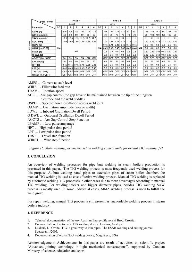
AMPS … Current at each level WIRE … Filler wire feed rate TRAV … Rotation speed AGC … Arc gap control (the gap have to be maintained between the tip of the tungsten electrode and the weld puddle) OSPD … Speed of torch oscillation across weld joint OAMP … Oscillation amplitude (weave width) I DWL … Inboard Oscillation Dwell Period O DWL … Outboard Oscillation Dwell Period AGCTS … Arc Gap Control Step Function LPAMP … Low pulse amperage HPT … High pulse time period LPT … Low pulse time period TRST … Travel step function WIRST … Wire step function Figure 16. Main welding parameters set on welding control unite for orbital TIG welding. [4]
3. CONCLUSION An overview of welding processes for pipe butt welding in steam boilers production is presented in this paper. The TIG welding process is most frequently used welding process for this purpose. At butt welding panel pipes to extension pipes of steam boiler chamber, the manual TIG welding is used as cost effective welding process. Manual TIG welding is replaced by automatic welding TIG processes in other cases due to more advantages according to manual TIG welding. For welding thicker and bigger diameter pipes, besides TIG welding SAW process is mostly used. In some individual cases, MMA welding process is used to fulfill the weld grove. For repair welding, manual TIG process is still present as unavoidable welding process in steam boilers industry. 4. REFERENCE 1. Tehnical documentation of factory Austrian Energy, Slavonski Brod, Croatia. 2. Documentation of automatic TIG welding device, Fronius, Austrija. 3. Lukkari, J. : Orbital-TIG- a great way to join pipes. The ESAB welding and cutting journal –
Svetsaren 1/2005. 4. Documentation of orbital TIG welding device, Magnatech, USA
Acknowledgement: Achievements in this paper are result of activities on scientific project “Advanced joining technology in light mechanical constructions”, supported by Croatian Ministry of science, education and sport.