automatic doors for lifts - fermator nordic ecc 230v-07.2015... · electronic driven ecc 230 v. 9....
TRANSCRIPT

AUTOMATIC DOORS FOR LIFTS
ENGInstallation manual.Automatic folding car door. Model: Electronic Driven ECC 230 V.
MAN-MMEC00000ENGTC-07.2015

AUTOMATIC DOORS FOR LIFTS
ELECTRONIC DRIVEN ECC 230 V2
INDEX
TECHNICAL DRAWING ...................................................................................... 3
PACKAGING CONTENT ..................................................................................... 4
OPERATOR ASSEMBLY INTO THE CABIN DOOR ........................................... 4
SILL ASSEMBLY ................................................................................................. 5
PANEL ASSEMBLY ............................................................................................. 5
CAR DOOR LOCK (OPTIONAL) ......................................................................... 6
CAR DOOR LOCK ADJUSTMENT .................................................................... 6
VERIFICATION OF CORRECT CAR DOOR LOCK DEVICE ADJUSTMENT .... 6
CLOSING PANELS ADJUSTMENT .................................................................... 7
MICROSWITCH REGULATION ........................................................................... 7
REOPENING CLUTCH ADJUSTMENT ............................................................... 8
ADJUSTMENT BETWEEN THE CAM AND THE WHEEL OF THE LOCKING DEVICE .. 8
CAR DOOR LOCK ADJUSTMENT ..................................................................... 9
USE OF THE MANUAL RESCUE (WITH CAR DOOR LOCK ONLY) ................ 9
ELECTRONIC DOOR OPERATOR CONTROL ECC 230 V .............................. 10
SEMIAUTOMATIC LANDING DOOR OPEN SYSTEM ..................................... 13
TECHNICAL SUPPORT .................................................................................... 15
DECLARATION OF CONFORMITY .................................................................. 16
- Flat spanner (6/7 (x2) - 8/9 (x2) - 10/11 (x2) - 12/13 (x2))- Allen spanner (2,5 - 3)- Screwdrivers (1 star tip and 1 flat tip)- Pliers with points to install internal and external elastic security rings.- Electric drill (drill bits 6,25 - 8,25)- Nylon mallet- Spirit level.- Pliers.
NECESSARY TOOLS

ELECTRONIC DRIVEN ECC 230 V 3
AUTOMATIC DOORS FOR LIFTS
100(1)
= =100
1.16
7
HL
+ 27
0
HL
+93
HL
HL
27
200
E
EPL
PL
70100(1)
6
100
10018
100186
EPL
PL
100186
550
*
15
E = =100
1.16
7
HL
+ 78
HL
+ 27
0
HL
HL
27
200
70
6
100
6
10021
550
*
30
2525
30
2525
10x32
ø22
10x32
ø22Rescue(2)
0’25
PL +
55
0’25
PL +
55
Rescue(2)
(1) Standard vision panel.(2) Optional complement (delivered only with the optional car door lock).
TECHNICAL DRAWING
FLUSH SILLFLUSH SILL
GLOBAL PANELS
HINGE DETAIL HINGE DETAILAluminium Glass panelsMetal sheet and
Vision panels
HINGE DETAIL
FERMATOR PANELS
1 1
1 12 2
2 23 3
3 3a 3b

AUTOMATIC DOORS FOR LIFTS
ELECTRONIC DRIVEN ECC 230 V4
Drill four holes (10,25 mm) in the entrance door posts and fix with four screws, the operator to the door posts using the slots of the operator side cartouches. Place the operator centred with the cabin and at the right height from the floor.
Verify that the side arms free the cabin door posts in the upper side of the operator, if this does not happen, cut the door posts until they are at 5 mm of the operator upper base.
OPERATOR ASSEMBLY INTO THE CABIN DOOR
One package for each door. Each package contains one full set of panels, operator, sill, toe guards, plastic bag with guide shoes (including nuts and bolts), and other accessories like retractable cam.
All of them supplied inside a box for an easier delivery as well as to assure a better delivery conditions of all the different parts.
If the door includes the optional car door lock, the set is delivered with the needed cams.
PACKAGING CONTENT
DIN 933 M8 x 20
Contact NFE25511 M8DIN 934 M8
100
50HL
58,5

ELECTRONIC DRIVEN ECC 230 V 5
AUTOMATIC DOORS FOR LIFTS
66
18
15
HL
+ 3
200
20
1 1
285
HL
100 1
86
PANEL ASSEMBLY
Remove the elastic rings that fix the moving shaft to the operator and move it 20 mm upwards.
Put the vertical shaft of the panel in the sill sleeve.
Push down the moving shaft, putting it in the panel vertical shaft, checking the alignment of both millings.
Place again the fixation rings of the lateral shaft on the operator.
Put back the elastic rings. Verify that supports and guides move freely in both aluminium rails.
W h e n p a n e l s a r e in its position, finish the installation tapping the shaft softly with a mallet where is shown with the arrows 1.
SILL ASSEMBLY
Check the vertical alignment with the operator. Drill three holes in the cabin floor which will coincide with the position of the screw holes in the sill rails. It is recommended to drill four big enough holes in the sill rails, coinciding with those in the sill to evacuate any waste.
Elastic ring
Lateral shaft
Panels
Sill Sleeve
Supportsand guides

AUTOMATIC DOORS FOR LIFTS
ELECTRONIC DRIVEN ECC 230 V6
> 1 mm < 2 mm
With the arms disassembled. If it is necessary, adjust the A and B nuts of the adjustment stop in order that the locking lever remains 1 or 2 mm from the retainer (Picture 1).
CAR DOOR LOCK ADJUSTMENT
ADJUSTMENT OF THE GAP BETWEEN THE RETAINER AND THE LEVER
Picture 1
A & B Nuts
VERIFICATION OF CORRECTCAR DOOR LOCK DEVICE ADJUSTMENT
If adjustment of the car door lock device has been correctly done, the central axis should be completely parallel with the hole of the support (see arrow in the zoomed image).
CAR DOOR LOCK (OPTIONAL)
Incase that, by conditions of the installation or by the regulations, is required that the opening of the door when the lift is not in floor lever, a car door lock (CDL) device could be delivered.

ELECTRONIC DRIVEN ECC 230 V 7
AUTOMATIC DOORS FOR LIFTS
The adjustment to increase or decrease the opening of the panels is done by means of the operating arm, without disassembling it, like is shown in the pictures below. Decreasing the A measure by screwing the arm body, it is possible to avoid that the panels leave a gap in the centre position, when the door is closed. Increasing the A measure by unscrewing the arm body, it is possible to avoid that the panels crash in the closing movement.
Each new arms adjustment requires a new verification of axis position in case the car door lock is installed (previous step). A
CLOSING PANELS ADJUSTMENT
I t i s n o t n e c e s s a r y t o disassemble the arm to do
the adjustment.
For proper adjustment of microswitch, you must verify that the arm of the contact is activated by the lateral axis while door is completely closed.
Movingarm terminal
MICROSWITCH REGULATION

AUTOMATIC DOORS FOR LIFTS
ELECTRONIC DRIVEN ECC 230 V8
In order to allow the correct operation of the car door lock with landing cam, a 5 mm distance must be between the cam and the CDL wheel (Picture 2 detail). In other hand, the cam must be installed in a centred position with respect to the wheel of the car door lock (Picture 2).
=
= 5 mm
263
mm
Figura 2
Picture 2 detail
ADJUSTMENT BETWEEN THE CAM AND THE WHEEL OF THE LOCKING DEVICE
Picture 2
19 mm
Recomended use for provided brackets.
REOPENING CLUTCH ADJUSTMENT
The adjustment of the clutch is done by means of the A nut. Turning the nut in the clockwise, the spring is tightened, and the door has more resistance to be reopened. Turning the A nut in the anti-clockwise, the spring is less tightened, and the door has less resistance to be reopened in case that an obstacle avoid the normal movement of the panels in the opening or closing operations.
Nut A
If it is necessary, adjust the position of the lock by means the brackets (A) supplied.
A

ELECTRONIC DRIVEN ECC 230 V 9
AUTOMATIC DOORS FOR LIFTS
Wheel
Landing cam
In case of needing to use the manual reopening, operate like is shown below:
The lock device wheel has adjustment possibilities in horizontal direction, in order to allow the correct situation with respect to the landing cam (Picture 3).
Picture 3
USE OF THE MANUAL RESCUE (WITH CAR DOOR LOCK ONLY)
1 .- Release the cable end from the end cable tip.2.- Pull the cable.3 .- Open the panels pulling both sides in the hinges (Like is shown in the picture).4 .- Replace the cable end in the initial position.
GLOBAL PANELSGLOBAL DETAIL
FERMATOR DETAIL
FERMATOR PANELS
The synchronization of the reopening clutch system is made in an automatic way when is done a compete opening and
closing operation.
CAR DOOR LOCK ADJUSTMENT
CAR DOOR LOCK WHEEL ADJUSTMENT POSSIBILITIES
The cable of the car door lock is delivered with the operator. To install it, slide the cable through the cable tips placed in the panel side.
5 mm
1
1
2
2
AUTOMATIC DOORS FOR LIFTS
ELECTRONIC DRIVEN ECC 230 V10
38
39
40
41
SP
EC
IAL
STA
ND
AR
D
ES
PE
CIA
L
DO
OR
MO
DE
L
STA
ND
AR
D
HE
AVY
MO
TOR
&E
NC
OD
ER
FUE
RZA
SA
FETY
OP
EN
SP
EE
D
VELO
CID
AD
AB
RIR
EN
CO
DE
R
FIN
AL
CA
RR
ER
ALI
MIT
SW
ITC
HE
STÁ
ND
AR
NO
AB
RIR
LA
TAPA
DO
NO
T O
PEN
TH
E CO
VER
WO
RK
ING
MO
TOR
MO
DE
LO P
UE
RTA
FUN
CIO
NA
MIE
NTO
VELO
CID
AD
CE
RR
AR
CLO
SE
SP
EE
D
TEST
PU
LSA
R P
AR
AVE
RIF
ICA
RPU
SH T
OCH
ECK
TH
E D
OO
R
F.C.
CER
RAR
CLO
SE L
.S
QCI
.EC0
0.C0
0EE
+12
V
ENTR
ADAS
INPU
TS
ALIM
ENT.
SUPP
LY
BAT
ERIA
BAT
TER
Y
ABIE
RTA
OPEN
FUS
20 A
SP
FUS
4A S
P
15 16 17 18 19 20
37 36 35F.
C.AB
RIR
OPE
N L
.S
34 33
F.C.
CER
RAR
CLO
SE L
.S
REA
BR
IR 2
REO
PEN
22930
REA
BR
IR 1
REO
PEN
12728
CON
EN
COD
ER
3132 2223 21
CON
TACT
OSE
RIE
SER
IAL
SW
ITCH
2526 24
C.SE
GU
RID
ADSAFE
TYSW
ITCH
OU
T 24
V11
SIN
EN
COD
ER
12CE
RR
ARCLO
SE
ABR
IRO
PEN
8
L5
N7
0V9
COM
10
0VSE
ÑAL
DE
PISO
FLO
OR
LEVE
L1413
PE6
WIT
HO
UT
EN
CO
DER
PE
SA
DA
ES
TÁN
DA
R
FLO
OR
LEVE
L
2 IN
PU
TS /
1 IN
PU
T W
ITH
OU
T B
ATTE
RY
1 IN
PU
T W
ITH
BAT
TER
Y
SEÑ
AL D
E PI
SO
2 EN
TRAD
AS /
1 EN
TRAD
A SI
N B
ATER
IA
1 EN
TRAD
A CO
N B
ATER
IA
WIT
HEN
CO
DER
...O
K S
TATU
S
Encl
avam
ient
o O
pcio
nal
Car
doo
r loc
k O
ptio
nal
Marrón / Brown
Con
tact
o Se
rieSe
rial C
onta
ct
Mic
rorru
ptor
final
car
rera
cer
rar
Mic
rorru
ptor
reap
ertu
ra c
onta
cto
cerra
do
Fina
l clo
se c
ours
e co
ntac
t
Reo
peni
ng C
onta
ct
Mot
or 2
4 V
DC
Roj
o / R
ed
Azul
/ Bl
ue
Enco
der
3
Mar
rón
/ Bro
wn
Mar
rón
/ Bro
wn
Azul
/ Bl
ue
Azul
/ Bl
ue
Mar
rón
/ Bro
wn
Mar
rón
/ Bro
wn
Mar
rón
/ Bro
wn
Azul
/ Bl
ue
12 V
2 A
h
24...
250
V
24...
250
V
230
VJ100
SW40
1SW
1
J200
J202-203
J201J206 F200
J204J205 J208
POT4
02PO
T401
POT4
00
J207J212
J401
IC400
SW400
J2092-ENT 1-ENT
J402
TESTJ2
11
Puen
te 1
E/2E
Mic
roco
ntro
lado
rM
icro
cont
rolle
r
Jum
per 1
E/2E
SW2
ELECTRONIC DOOR OPERATOR CONTROL ECC 230 V

ELECTRONIC DRIVEN ECC 230 V 11
AUTOMATIC DOORS FOR LIFTS
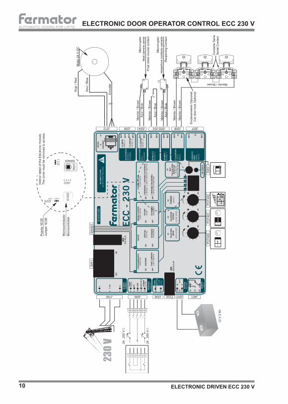
F200 Security fuse: 20 A a 240 V. Fast acting.
IC400 MICRO-SWITCH (sticker with program version and week-year): The program connects and disconnects the motor avoiding any over-tension or spark in the opening-closing micro-switches. The system follows the new directives of electromagnetic compatibility.
J100 230 V supply: 230 V supply single phase AC (neutral-earth-phase).
J200 Control inputs OPEN-COMMON-CLOSE: This circuit allows working with 1 or 2 signals. With two inputs it is necessary to activate independently the opening or closing signal to do the movement. With one entry only the closeing signal needs to be connected and without any signal the door will open by itself. Only indicate the functioning mode placing the internal bridge (1E or 2E) in the right position. The signals accept any value of tension from 24 to 250 V, whether in AC or DC. The signal is applied between common (COM) and open or between common (COM) and close.
0 VCom 10
8
24 V12
8
10
12
0 VCom24 V
EXTERNAL VOLTAGE INPUT:
Close
Open
Voltage 24...250 VCLOSE
Voltage 24...250 VOPEN
VOLT FREE CONTACT INPUT:
Close
Open
CLOSE
OPEN
J201 Battery: 12 V 2 Ah minimum.
J202-203 REAP1-2 re-opening connections 1 and 2: This connections are in serial and when they activate the door reopens. It is very useful for the photocell, the cabin push-button or any other device that initiates the reopening process when the
Components:
ELECTRONIC DOOR OPERATOR CONTROL ECC 230 V
Step by step checklist for a correct functioning of the circuit1.- Connect following the diagram2.- In 1 input mode (J209 1E), without close signal the door should open by itself if the signal is not
activated until the end position.3.- For 2 input mode (J209 2E) without signal the door should not move. Activating the signal (open or
close) the door will move accordingly until the end.4.- Push the TEST (SW400) to do a whole movement.5.- Do an obstruction when closing to verify that the door reopens. Do the same when closing to verify
that the door stops and reassumes closing.
ATENTIONElectrical hazard. Always disconnect the circuit before working.
AUTOMATIC DOORS FOR LIFTS
ELECTRONIC DRIVEN ECC 230 V12
ELECTRONIC DOOR OPERATOR CONTROL ECC 230 V
door starts to close. They do not activate when the door is closed. As it is a serial connection it is necessary to over-bridge the free one.
J204 Limit switch connection if used with encoder. J205 Limit switch connection if used without encoder (optional). J206 Floor Signal: This input activates the open movement in emergency rescue mode in case of power failure, through a 12 V battery to rescue the passengers from the lift. The door only will open if this signal is bridged (Normally Open). J207 Connection SERIAL EXIT-ENTRANCE: It must be connected in series with the external lock series. J208 Direct connection between the entrance and the exit without any influence in the electrical circuit function. J209 1 input (1E ) or 2 inputs (2E ) mode: The jumper position allows to program with only 1 closing signal (the CAM signal) or with 2 independent signals (open-close). J211 Jumper to enable the re-opening contact 2 (J203), with photocells or re-opening devices. J212 Encoder or end stroke programation bridge. J401 Relay door open contacts (NC-COM-NA): Commuted contacts of the door open relay indicator which allows to inform the manoeuvres. J402 Connector for factory testings. POT400 Open Speed. POT401 Close Speed. POT402 Force adjustment applied at the final opening movement. SW1 On / Off SW2 TEST pushing button: It allows to do a complete opening-closing manoeuvre. SW401 Programation DIP: 1→ Operation with encoder (ON) or End Stroke (OFF). 2→ Standard Motor (OFF) or Special One (ON). 3→ Heavy doors. 20% extra torque will be supplied by the motor (ON). 4→ Floor level in normal operation and 2 inputs with or without battery, and floor level in normal operation and 1 input without battery (ON).

ELECTRONIC DRIVEN ECC 230 V 13
AUTOMATIC DOORS FOR LIFTS
SEMIAUTOMATICLANDING DOOR OPEN SYSTEM
Place the retractive cam in the cabin door. With the door closed, the cam will remain folded (Picture 1) .When the door is open, the cam remains unfolded actioning the roller in the landing lock (Picture 2).
45 10
7520
2248
25
7520
2248 10
0
80
25
PL
PL
100
35
32
OPEN SYSTEM WITH RETRACTABLE CAM (SIDE ACTING)
Picture 1
Picture 2

AUTOMATIC DOORS FOR LIFTS
ELECTRONIC DRIVEN ECC 230 V14
OPEN SYSTEM WITH RETRACTABLE CAM (FRONTAL ACTING)5
32
70
50
20
5045
(± 1
1)
100
10
5
45
70
50PL 25
755
5050
35
PL 25
2010
020
100
45
75
SEMIAUTOMATICLANDING DOOR OPEN SYSTEM
Picture 1
Picture 2
Place the retractive cam in the cabin door. With the door closed, the cam will remain folded (Picture 1).When the door is open, the cam remains unfolded actioning the roller in the landing lock (Picture 2).

ELECTRONIC DRIVEN ECC 230 V 15
AUTOMATIC DOORS FOR LIFTS TECHNICAL SUPPORT
FAILURE POSSIBLE CAUSE SOLUTION- Operator doesn’t open or close, it keeps stopped.
- No power arrives. - Check input voltage at terminals.
- Power arrives to the circuit but does not open or close.
- Check fuse. - Replace fuse.
- Operator works but panels do not move.
- Drive arm shafts do not move the panels.- Drive arm shaft do not gear with clutch.- Panels are blocked.
- Check drive arm shaft if correctly fitted into the panel.- Adjust clutch spring nut.- Unlock panels and check sill guide shoe channels.
- Door opens but does not close.
- No closing signal arrives.- Motor does not disconnect at the end of opening travel.
- Check the closing signal at the entrance of the circuit.- Possible encoder error. Change the encoder.
- Reopening continuously activated.
- Obstacle in the car doorway.- Loose clutch spring.- Panels get blocked during closing travel.
- Remove the obstacle or clean the bottom sill.- Adjust the spring.- Clean and grease the bushings and hinges.
- Power failure in panels closing signal.
- Any of the serial contacts does not give signal.
- Check the contact works centred and it is free of soot or dirt.
- Panels do not close or open completely.
- Disadjustment in regulation of acting arm.- Central axis does not rotate 180º.
- Adjust the arm as described on page 6.- Adjust nuts A and B (Page 5).
- Operator closes but does not open.
- Floor level signal bridge is not activated.
- Bridge floor level signal.

DECLARATION OF CONFORMITY
Tecnolama, S.A.Ctra. Constantí Km. 343206 REUS (Spain)
We hereby declare that the products mentioned below conform with the following E.U. council directives:
Tecnolama, S.A. 2015
Josep Vilà GomisAdministrator
Norm EN 81-1/2DIRECTIVE 2006/42/EC (Machinery directive), DIRECTIVE 2014/30/UE
(Electromagnetic compatibility), of the European Parliament and of the Council.
ATENTION: Any type of modification not reflexed in this manual, before testing it should be notified to our Tecnichal Department.FERMATOR accepts no responsability in the event of any damage produced in the equipment described in this manual and associated installation if the instructions given have not been followed.FERMATOR reserves the rights to modify the products specifications of this technical brochure without any previous advise.
Tecnolama, S.A. ● Ctra. Constantí, Km 3 ● 43206 REUS (Spain) ● Tel.: +34 977 774 065Fax: +34 977 771 615 ● www.fermator.com ● e-mail: [email protected]