automatic doors for lifts - elevator tradingecc... · e-mail:[email protected] declaration of...
TRANSCRIPT

MODEL ECC FOLDING DOOR ASSEMBLY AND MAINTENANCE
MANUAL
Rev.: 04.2009
AUTOMATIC DOORS FOR LIFTS
MAN-MMPLINGDCTL*MANMMPLINGDCTL*

AUTOMATIC DOORS FOR LIFTS
FOLDING DOORS2
INDEX
PACKAGING CONTENT .................................................................................3
TECHNICAL DRAWING .................................................................................3
OPERATOR ASSEMBLY INTO THE CABIN DOOR .............................................4
SILL ASSEMBLY...........................................................................................4
PANEL ASSEMBLY .......................................................................................4
CLOSING PANELS ADJUSTMENT ..................................................................5
REOPENING CLUTCH ADJUSTMENT .............................................................5
CAR DOOR LOCK (OPTIONAL) .......................................................................6
CAR DOOR LOCK ADJUSTMENT ....................................................................6
USE OF THE MANUAL RESCUE (WITH CAR DOOR LOCK ONLY) ......................7
ELECTRONIC DOOR OPERATOR CONTROL DCB .............................................8
SEMIAUTOMATIC LANDING DOOR OPEN SYSTEM .......................................10
DECLARATION OF CONFORMITY .................................................................12
-Flat spanner (6/7 (x2) - 8/9 (x2) - 10/11 (x2) - 12/13 (x2))
-Allen spanner (2,5 - 3)
-Screwdrivers (1 star tip and 1 flat tip)
-Pliers with points to install internal and external elastic security rings.
-Electric drill (drill bits 6,25 - 8,25)
-Nylon mallet
-Spirit level.
-Pliers.
NECESSARY TOOLS

FOLDING DOORS 3
AUTOMATIC DOORS FOR LIFTS
= =
100
1167
27
200
70
100(1) 6
100
6
100 18
100
18
6
550
*
Rescate(2)
30
25 25
One package for each door. Each package contains one full set of panels, operator, sill, toe guards, plastic bag with guide shoes (including nuts and bolts), and other accessories like retractable cam.
All of them supplied inside a box for an easier delivery as well as to assure a better delivery conditions of all the different parts.
If the door includes the optional car door lock, the set is delivered with the needed cams.
(1) Estandar vision panel.
Entrance = E
E
PL
HL
+ 7
8
HL
+ 2
70
HL
HL
PL
0’2
5P
L+5
5
22
10x32
(2) Optional complement (delivered only with the optional car door lock)
PACKAGING CONTENT
TECHNICAL DRAWING
RAISED SILL
Rescue

AUTOMATIC DOORS FOR LIFTS
FOLDING DOORS4
Drill four holes (10,25mm.) in the entrance door posts and fix with four screws, the operator to the door posts using the slots of the operator side cartouches. Place the operator centred with the cabin and at the right height from the floor.Verify that the side arms free the cabin door posts in the upper side of the operator, if this does not happen, cut the door posts until they are at 5mm. of the operator upper base.
+36
6
18285
15100
18
6
PANEL ASSEMBLY
Remove the elastic rings that fix the moving shaft to the operator and move it 20mm upwards.
Put the vertical shaft of the panel in the sill sleeve.
Push down the moving shaft, putting it in the panel vertical shaft, checking the alignment of both millings.
Place again the fixation rings of the lateral shaft on the operator.
Put back the elastic rings. Verify that supports and guides move freely in both aluminium rails.
SILL ASSEMBLY
Check the vertical alignment with the operator. Drill three holes in the cabin floor which will coincide with the position of the screw holes in the sill rails. It is recommended to drill four big enough holes in the sill rails, coinciding with those in the sill to evacuate any waste.
OPERATOR ASSEMBLY INTO THE CABIN DOOR
Elastic ring
Lateral shaft
Panels
Sill Sleeve
Supportsand
guides

FOLDING DOORS 5
AUTOMATIC DOORS FOR LIFTS
The adjustment to increase or decrease the opening of the panels is done by means of the operating arm, without disassembling it, like is shown in the pictures below. Decreasing the A measure by screwing the arm body, it is possible to avoid that the panels leave a gap in the centre position, when the door is closed. Increasing the A measure by unscrewing the arm body, it is possible to avoid that the panels crash in the closing movement.
CLOSING PANELS ADJUSTMENT
Movingarm terminal
REOPENING CLUTCH ADJUSTMENT
The adjustment of the clutch is done by means of the A nut. Turning the nut in the clockwise, the spring is tightened, and the door has more resistance to be reopened. Turning the A nut in the anti-clockwise, the spring is less tightened, and the door has less resistance to be reopened in case that an obstacle avoid the normal movement of the panels in the opening or closing operations.
Nut A
A
I t i s n o t n e c e s s a r y t o disassemble the arm to do
the adjustment.

AUTOMATIC DOORS FOR LIFTS
FOLDING DOORS6
> 1 mm. < 2 mm.
CAR DOOR LOCK (OPTIONAL)
If it is necessary, adjust the A and B nuts of the adjustment stop in order that the locking lever remains 1 or 2mm. from the retainer (Picture 1).
In order to allow the correct operation of the car door lock with landing cam, a distance between 5 and 10mm. must be between the cam and the CDL wheel (picture 2 detail). In other hand, the cam must be installed in a centred position with respect to the wheel of the car door lock (Picture2).
=
= > 5 < 10mm.
26
3m
m.
Figura 2
Picture 2 detail
CAR DOOR LOCK ADJUSTMENT
ADJUSTMENT OF THE GAP BETWEEN THE RETAINER AND THE LEVER
ADJUSTMENT BETWEEN THE CAM AND THE WHEEL OF THE LOCKING DEVICE
Incase that, by conditions of the installation or by the regulations, is required that the opening of the door when the lift is not in floor lever, a car door lock (CDL) device could be delivered.
Picture 2
Picture 1
A & B Nuts
If it is necessary, adjust the position of the lock by means the brackets (A) supplied.
A
19mm.
Recomended use for provided brackets.

FOLDING DOORS 7
AUTOMATIC DOORS FOR LIFTS
Wheel
Landing cam
In case of needing to use the manualreopening, operate like is shown below:
The lock device wheel has adjustment possibilities in horizontal direction, in order to allow the correct situation with respect to the landing cam (Picture 3).
Picture 3
USE OF THE MANUAL RESCUE (WITH CAR DOOR LOCK ONLY)
1 .- Release the cable end from the end cable tip.2 .- Open the panels pulling both sides in the hinges
(Like is shown in the picture).3 .- Replace the cable end in the initial position.
Detail 1
The synchronization of the reopening clutch system is made in an automatic way when is done a compete opening and
closing operation.
CAR DOOR LOCK ADJUSTMENT
C A R D O O R L O C K W H E E L ADJUSTMENT POSSIBILITIES
The cable of the car door lock is delivered with the operator. To install it, slide the cable through the cable tips placed in the panel side.
5 mm.

AUTOMATIC DOORS FOR LIFTS
FOLDING DOORS8
SW1 On / Off
SW2 TEST pushing button: It allows to do a complete opening-closing manoeuvre.
SW401 Programation DIP: 1→ Operation with encoder (ON) or End Stroke (OFF). 2→ Standard Motor (OFF) or Special One (ON). 3 y 4→ Free.
F200 Security fuse: 20A 240V. Fast acting.
Motor 24V DC
Microrruptorreapertura contacto cerrado
Contacto Serie Serial Contact
Marrón/Brown Marrón/Brown
Mar
rón
/Bro
wn
Marrón/Brown
Marrón/Brown
Marrón/Brown
Azul/Blue
Azul/Blue
Azul/Blue
Encoder
Rojo
/Red
Azul/Blue
Reopening Contact
Microrruptorfinal carrera cerrar
Final close course contact
3J2
12J2
05J2
04J2
03
J208
J2
02
SW1
F200
SEÑAL PISOFloor signal
BATERIA Battery
12 161514 13
IC4
00
J212
J205
J40
0
J100 J200 J206 J201 J401 J207
J204
J203
J202
J208
PO
T400
PO
T401
PO
T402
SW
400S
W40
1
20A. FUSEQuick Blow
J209
C. SERIESerial Switch
RELÉ ABIERTOOpenRelay
CERRARClose
ABRIROpen
J40
2
1ON
DIP
23
4+ -
12V
TEST
FCA
FCC
(opcional/optional)
J211
MOTOR&
ENCODER
Step by step checklist for a correct functioning of the circuit
1.- Connect following the diagram
2.- In 1 input mode (J209 1E), without close signal the door should open by itself if the signal is not activated until the end position.
3.- For 2 input mode (J209 2E) without signal the door should not move. Activating the signal (open or close) the door will move accordingly until the end.
4.- Push the TEST (PL1) to do a whole movement.
5.- Do an obstruction when closing to verify that the door reopens. Do the same when closing to verify that the door stops and reassumes closing.
ELECTRONIC DOOR OPERATOR CONTROL DCB
ATENTIONElectrical hazard. Always
disconnect the circuit before working.
Components:

FOLDING DOORS 9
AUTOMATIC DOORS FOR LIFTS ELECTRONIC DOOR OPERATOR CONTROL DCB
J100 220V supply: 220 Volts supply single phase AC (neutral-earth-phase).
J200 Control inputs OPEN-COMMON-CLOSE: This circuit allows working with 1 or 2 signals. With two inputs it is necessary to activate independently the opening or closing signal to do the movement. With one entry only the closeing signal needs to be connected and without any signal the door will open by itself. Only indicate the functioning mode placing the internal bridge (1E or 2E) in the right position. The signals accept any value of tension from 24 to 240 volts, whether in AC or DC. The signal is applied between COMUN (COM) and open or between COMUN (COM) and close.
J206 Floor Signal: This input activates the open movement in emergency rescue mode in case of power failure, through a 12V battery to rescue the passengers from the lift. The door only will open if this signal is bridged (Normally Open).
J201 Battery: 12V 2Ah minimum.
J401 Temporized relay with contacts (NC-COM-NA): Commuted contacts of a temporized relay which allows to maintain the cam signal for 6 seconds after the closing signal is activated. It is useful for manoeuvres that need a longer activating time.
J207 Connection SERIAL EXIT-ENTRANCE: It must be connected in series with the external lock series.
J300 Motor connection: Compatible with the actual connections.
J202-203 REAP1-2 re-opening connections 1 and 2: This connections are in serial and when they activate the door reopens. It is very useful for the photocell, the cabin push-button or any other device that initiates the reopening process when the door starts to close. They do not activate when the door is closed. As it is a serial connection it is necessary to over-bridge the free one.
J204 Limit switch connection if used with encoder.
J205 Limit switch connection if used without encoder (optional).
J211 Jumper to enable the re-opening contact 2 (J203), with photocells or re-opening devices.
J208 Direct connection between the entrance and the exit without any influence in the electrical circuit function.
J212 Encoder or end stroke programation bridge.
IC400 MICRO-SWITCH (sticker with program version and week-year): The program connects and disconnects the motor avoiding any over-tension or spark in the opening-closing micro-switches. The system follows the new directives of electromagnetic compatibility.
J209 1 input (1E) or 2 inputs (2E) mode: The jumper position allows to program with only 1 closing signal (the CAM signal) or with 2 independent signals (open-close).
J402 Connector for factory testings.
AUTOMATIC DOORS FOR LIFTS
FOLDING DOORS10
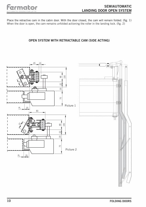
SEMIAUTOMATICLANDING DOOR OPEN SYSTEM
Place the retractive cam in the cabin door. With the door closed, the cam will remain folded. (fig. 1) When the door is open, the cam remains unfolded actioning the roller in the landing lock. (fig. 2)
45 1075
2022
48
25
7520
2248 10
0
80
25
PL
PL
100
35
32
OPEN SYSTEM WITH RETRACTABLE CAM (SIDE ACTING)
Picture 1
Picture 2

FOLDING DOORS 11
AUTOMATIC DOORS FOR LIFTS
OPEN SYSTEM WITH RETRACTABLE CAM (FRONTAL ACTING)
5
32
70
50
20
5045
(± 1
1)
100
10
5
45
70
50PL 25
755
5050
35
PL 25
2010
020
100
45
75
SEMIAUTOMATICLANDING DOOR OPEN SYSTEM
Picture 1
Picture 2

Ctra. Constantí, Km 3 - 43206 REUS (Spain) - Tel. +34 977 774 065 - Fax +34 977 771 615 h t t p : / / w w w . f e r m a t o r . c o m e - m a i l : c o m e r c i a l @ f e r m a t o r . c o m
DECLARATION OF CONFORMITY
Tecnolama, S.A.Ctra. Constantí Km. 343206 REUS (Spain)
Herewith declares that the products mentioned below conform with the following E.U. council directives:
Tecnolama S.A., 2009
Josep Vilà GomisAdministrator
E.U. council directive of electromagnetic compatibility and immunity 89/336-CEE, conform with Norms EN12015 and EN12016,
about lift doors:
Manoeuvre system for lift doors 40/10 mechanical model(EMI-370)
ATENTION: Any type of modification not reflexed in this manual, before testing it should be notified to our Tecnichal Department.TECNOLAMA declines all responsability in the case of damages produced in the operator and installation, if the instructions given have not been followed.TECNOLAMA reserves the rights to modify the products specifications of this technical brochure without any previous advise.