automatic air conditional control system mohd nor …
TRANSCRIPT
AUTOMATIC AIR CONDITIONAL CONTROL SYSTEM
MOHD NOR IDRUS BIN MAT SHARIFF
A thesis submitted
in fulfillment of the requirements for the award of the degree of
Bachelor of Electrical and Electronic Engineering (Electronics)
Faculty of Electrical & Electronics Engineering
University Malaysia Pahang
NOVEMBER, 2008
ii
“All the trademark and copyrights use herein are property of their respective owner.
References of information from other sources are quoted accordingly; otherwise the
information presented in this report is solely work of the author.”
Signature : ____________________________
Author : MOHD NOR IDRUS BIN MAT SHARIFF
Date : 12 NOVEMBER 2008

iii
To my beloved mother and father

iv
ACKNOWLEDGEMENT
Firstly, I am very grateful to the almighty ALLAH S.W.T for giving me the key and
opportunity to accomplish my Final Year Project.
Then, I want to thank Miss. Rohana Bt Abdul Karim, my supervisor because give
me guide and her help during making this project. I really appreciate her tips and guide that
give me pleasant to solve this project and I can solve the entire problem that have. Without
her, maybe I cannot be able to finish this project.
Secondly, for the individual that taking their part in my project, such as my course
mate, they also give their participating and cooperating to help my finish this project
successfully. I would thank anyone, who is involve and help me direct or indirectly because
I can’t finish this project in time given even I have problem, but at last I can finish it.
Most importantly, I wish my gratitude to my parents for their support,
encouragement, understanding, sacrifice and love.
v
ABSTRACT
An air conditioner is an appliance, system, or mechanism designed to extract heat
from an area using a refrigeration cycle. In construction, a complete system of heating,
ventilation, and air conditioning is referred to as HVAC. Its purpose, in the home or in the
car, is to provide comfort during hot days and nights. There are certain problems happen
when user uses the air conditioner. The conventional air conditional uses more energy, need
to pay more bills and waste the energy. This project mainly concern to use PIC to control
NPN power transistor further drive air conditional and LEDs on. This situation happen
when the sensor detected certain temperature and the movement. The value of environment
temperature will display on a LCD screen. When sensor did not detect the movement and
environment temperature is below the setting point so the air conditioner will off
automatically.

vi
ABSTRAK
Penghawa dingin merupakan suatu alat atau mesin yang telah di cipta untuk
melakukan proses penyejatan haba dari persekitaran menggunakan proses penyejukan.
Dalam suatu proses pemanas yang sempurna, pengudaraan dan keadaan udara merujuk
kepada HVAC. Penghawa dingin selalunya digunakan di rumah atau di dalam kereta.
Penghawa dingin memberi keselesaan kepada pengguna dalam cuaca panas dan di waktu
malam. Terdapat beberapa masalah yang timbul kesan daripada penggunaan penghawa
dingin.Antara masalah tersebut ialah menggunakan tenaga yang banyak untuk beroperasi,
perlu membayar bil elektrik yang mahal dan membazir tenaga elektrik. Projek ini
menggunakan PIC yang akan mengawal tenaga NPN transistor dan seterusnya
menggerakan penghawa dingin dan LED menyala. Keadaan ini berlaku bila sensor
mengesan perubahan suhu persekitaran dan pergerakan yang berlaku. Nilai perubahan suhu
akan terpapar pada LCD skrin. Bila sensor tidak mengesan pergerakkan dan suhu
persekitaran berada pada bawah suhu kawalan maka penghawa dingin akan terpadam
secara automatik.
vii
TABLES OF CONTENTS
CHAPTER TITLE PAGE
1 INTRODUCTION
1.1 Overview 1
1.2 Objective Research 3
1.3 Project Scope 3
1.4 Problem Statement 4
1.5 Thesis Organization 4
2 LITERATURE REVIEW
2.1 Energy Efficiency 5
2.2 Power Consumption 8
2.3 Load Management 9
2.4 Room Air Conditioner 13
2.5 Load Control 17
2.6 The Electricity Savings 22
2.7 PIC Microcontroller 26
2.8 Advantages of C++ 28
2.9 Passive Infra-Red 28
viii
3 HARDWARE AND SOFTWARE DEVELOPMENT
3.1 Introduction 31
3.2 Hardware Design 34
3.2.1 Power Transistor 34
3.2.2 Temperature Sensor 34
3.2.3 PIC 16F876A 35
3.2.4 Interface PIC16F876A With
Temperature Sensor 36
3.2.5 Interface PIC16F876A with LCD 37
3.2.6 Power Supply for Circuit 38
3.2.7 ICSP for Programming PIC
Microcontroller 38
3.2.8 Push Button as Input for PIC
Microcontroller 39
3.2.9 LED as Output for PIC Microcontroller 39
3.2.10 Interface PIC16F876A with DC
Brushless Fan 39
3.2.11 PIR (Passive Infra-Red) Sensor 40
3.2.12 Getting Start 41
3.3 Software Design 43
3.3.1 Analog to Digital Converter
(A/D) Module 43

ix
4 RESULT AND DISCUSSION
4.1 Introduction 45
4.2 Sensor Movement Result 46
4.3 Initial Sensor Result 46
4.4 Final Sensor Result 47
4.5 Data Analysis 48
4.6 Discussion of the project 49
5 CONCLUSION AND RECOMMENDATIONS
5.1 Conclusion 50
5.2 Future Recommendation 51
5.3 Costing And Commercialization 51
REFERENCE 54-56
Appendices A 57-66
Appendices B 67-69
Appendices C 70-76
Appendices D 77-87
x
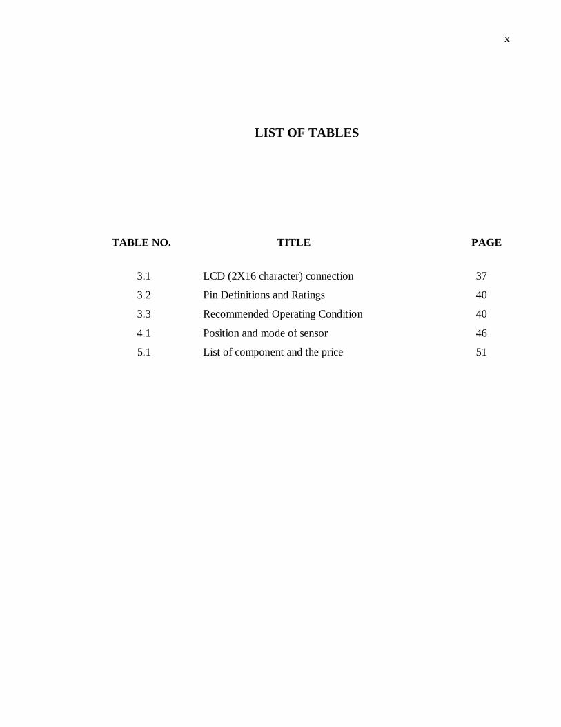
LIST OF TABLES
TABLE NO. TITLE PAGE
3.1 LCD (2X16 character) connection 37
3.2 Pin Definitions and Ratings 40
3.3 Recommended Operating Condition 40
4.1 Position and mode of sensor 46
5.1 List of component and the price 51
xi
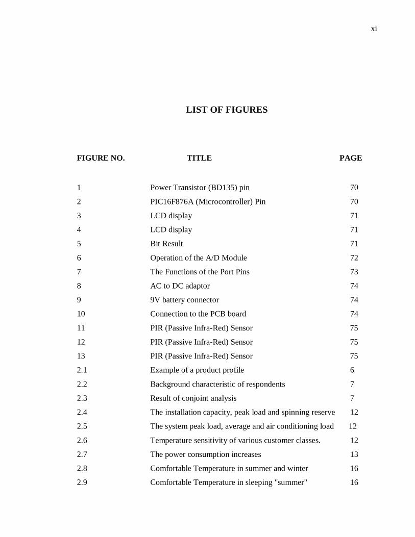
LIST OF FIGURES
FIGURE NO. TITLE PAGE
1 Power Transistor (BD135) pin 70
2 PIC16F876A (Microcontroller) Pin 70
3 LCD display 71
4 LCD display 71
5 Bit Result 71
6 Operation of the A/D Module 72
7 The Functions of the Port Pins 73
8 AC to DC adaptor 74
9 9V battery connector 74
10 Connection to the PCB board 74
11 PIR (Passive Infra-Red) Sensor 75
12 PIR (Passive Infra-Red) Sensor 75
13 PIR (Passive Infra-Red) Sensor 75
2.1 Example of a product profile 6
2.2 Background characteristic of respondents 7
2.3 Result of conjoint analysis 7
2.4 The installation capacity, peak load and spinning reserve 12
2.5 The system peak load, average and air conditioning load 12
2.6 Temperature sensitivity of various customer classes. 12
2.7 The power consumption increases 13
2.8 Comfortable Temperature in summer and winter 16
2.9 Comfortable Temperature in sleeping "summer" 16

xii
2.10 Optimum Characteristics of Temperature Control 17
2.11 Membership function: Actual temperature in a building 21
2.12 Resulting air conditioner load curves 22
2.13 Frequency of compressor 25
2.14 The thermal comfortable control 25
2.15 The power consumed 26
3.1 Hardware overview 32
3.2 Software overview 33
3.3 Temperature sensor 34
3.4 Temperature sensor 35
3.5 Step for soldering 2510 connector 42
3.6 A/D Control Register 44
4.1 Initial location 47
4.2 Detect movement 48
xiii
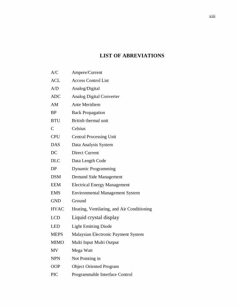
LIST OF ABREVIATIONS
A/C Ampere/Current
ACL Access Control List
A/D Analog/Digital
ADC Analog Digital Converter
AM Ante Meridiem
BP Back Propagation
BTU British thermal unit
C Celsius
CPU Central Processing Unit
DAS Data Analysis System
DC Direct Current
DLC Data Length Code
DP Dynamic Programming
DSM Demand Side Management
EEM Electrical Energy Management
EMS Environmental Management System
GND Ground
HVAC Heating, Ventilating, and Air Conditioning
LCD Liquid crystal display
LED Light Emitting Diode
MEPS Malaysian Electronic Payment System
MIMO Multi Input Multi Output
MV Mega Watt
NPN Not Pointing in
OOP Object Oriented Program
PIC Programmable Interface Control

xiv
PM Post meridiem
PNN Probabilistic Neural Network
RAM Random Access Memory
R&D Research and development
SEER Seasonal Energy Efficiency Ratio
TPC Transaction Processing Performance Council
VFC Variable Frequency Control
VR Voltage Resistor

xv
LIST OF APPENDICES
APPENDIX TITLE PAGE
A SOFTWARE DEVELOPMENT
PIC PROGRAMMING 57
B PIC MICROCONTROLLER CIRCUIT 67
C FIGURES 70
D DATA SHEET 77
1
CHAPTER 1
INTRODUCTION
1.1 Overview
An air conditioner is an appliance, system, or mechanism designed to extract
heat from an area using a refrigeration cycle. In construction, a complete system of
heating, ventilation, and air conditioning is referred to as HVAC. Its purpose, in the
home or in the car, is to provide comfort during hot days and nights. Thermostats control
the operation of HVAC systems, turning on the heating or cooling systems to bring the
building to the set temperature.
Typically the heating and cooling systems have separate control systems so that
the temperature is only controlled "one-way”. In winter, a building that is too hot will
not be cooled by the thermostat. Thermostats may also be incorporated into facility
energy management systems in which the power utility customer may control the overall
energy expenditure. In addition, a growing number of power utilities have made
available a device which, when professionally installed, will control or limit the power
to an HVAC system during peak use times in order to avoid necessitating the use of
rolling blackouts.

2
In a thermodynamically closed system, any energy input into the system that is
being maintained at a set temperature (which is a standard mode of operation for modern
air conditioners) requires that the energy removal rate from the air conditioner increase.
This increase has the effect that for each unit of energy input into the system requires the
air conditioner to remove that energy. In order to do that the air conditioner must
increase its consumption by the inverse of its efficiency times the input unit of energy.
So I can state here that Air conditional use more energy than other electrical equipment.
For residential homes, some countries set minimum requirements for energy
efficiency. In the United States, the efficiency of air conditioners is often (but not
always) rated by the Seasonal Energy Efficiency Ratio (SEER). The higher the SEER
rating, the more energy efficient is the air conditioner. The SEER rating is the BTU of
cooling output during its normal annual usage divided by the total electric energy input
in watt-hours (W·h) during the same period. So when we use the air conditioner, we
need to pay more bills.
The use of electric/compressive air conditioning puts a major demand on the
nation's electrical power grid in warm weather, when most units are operating under
heavy load. During peak demand, additional power plants must often be brought online,
usually natural gas fired plants because of their rapid startup. So when the user uses the
air conditioner, some time they don‟t realize that they have waste lot of energy every
day.
For the user that uses the air conditioner, there is a certain way to save some
energy. The savings can be significant when set the thermostat at 1°C or higher (Cooling
model) / 2°C or lower (Heating model). For each degree that raises the thermostat
setting, reduce seasonal cooling costs by 10%. They also can use a ceiling fan or
portable fan to supplement the air conditioning. A fan can make feel a few degrees
3
cooler so can set the thermostat a few degrees higher and save on cooling costs. User
also must make sure the air conditioner is not blocked. A free flowing air conditioner
operates most efficiently. Filters should be checked every 2 weeks. Dirty filters may
reduce cooling and heating efficiency and when air conditioning is on, keep doors and
windows closed. Turn off kitchen or bathroom exhaust fans when the air conditioning is
operating.
1.2 Objective Research
The main objective of this project is to design and develop a device that it can
display the environment temperature value on LCD screen and it can Able to switch
on/off air conditioner automatically based on movement detection and environment
temperature
1.3 Project Scope
This project is focused to design and build the prototype of automatic air
conditional control system that would be a starting point to build the realistic automatic
air conditional control system. Therefore, this prototype will cover the scope as
followed.
(i) Based on air conditioner.
4
1.4 Problem Statement
In this project, there are several problems when user uses the air conditioner. The
problem they have face is air conditioner use lot of energy compare to other electrical
item. The air conditioner also wastes the energy when there is no user in the room when
the air conditioner is on. Lastly the problem they face is they need to pay more bills.
1.5 Thesis Organization
This thesis consists of five chapters. This chapter discuss about overview of
project, objective research, project scope, problem statement and thesis organization.
Chapter 2 contains a detailed description of automatic air conditional control system. It
will explain about the concept of automatic air conditional control system, the
application of this system and the involved component in this project.
Chapter 3 includes the project methodology. It will explain how the project is
organized and the flow of process in completing this project. Also in this topic discusses
the methodology of the system, circuit design, software design and the hardware design.
Chapter 4 will be discussing about the result obtained in this project and a discussion
about the result. Finally, the conclusions for this project are presented in chapter 5. This
chapter also discusses about the recommendation for the project and for the future
development.
5
CHAPTER 2
LITERATURE REVIEW
2.1 Energy Efficiency
In early 1997, the energy research group of University Technology Malaysia
initiated a research on the feasibility of standardization and appliance labeling program
in Malaysia. Currently, no regulation has been imposed on the manufacturer to produce
an energy efficient appliance. However the government through the Department of
Electricity and Gas supply Malaysia has planned to enforce minimum energy
performance standards (MEPS) for some domestic electric appliance. Appliance
standards are a set of procedure and regulations which prescribe the energy performance
of manufactured products, sometimes prohibiting the manufacture of products less
energy efficient than the minimum standards. [1]
2.1.1 Room Air Conditioner
Malaysia, like many other developing countries with hot and humid climates, has
been experiencing dramatic growth in the number and use of room air conditioners. As
the economy recovers and income level rise, more consumers will seek air conditioning.
Since there is potential of substantial energy saving in the domestic room air
6
conditioning sector, the establishment of energy efficiency standard for room air
conditioner has been giving priority. [2]
2.1.2 Minimum Efficiency
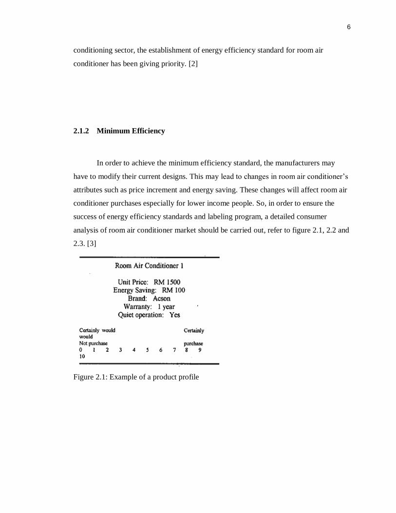
In order to achieve the minimum efficiency standard, the manufacturers may
have to modify their current designs. This may lead to changes in room air conditioner‟s
attributes such as price increment and energy saving. These changes will affect room air
conditioner purchases especially for lower income people. So, in order to ensure the
success of energy efficiency standards and labeling program, a detailed consumer
analysis of room air conditioner market should be carried out, refer to figure 2.1, 2.2 and
2.3. [3]
Figure 2.1: Example of a product profile
7
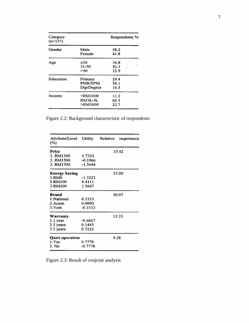
Figure 2.2: Background characteristic of respondents
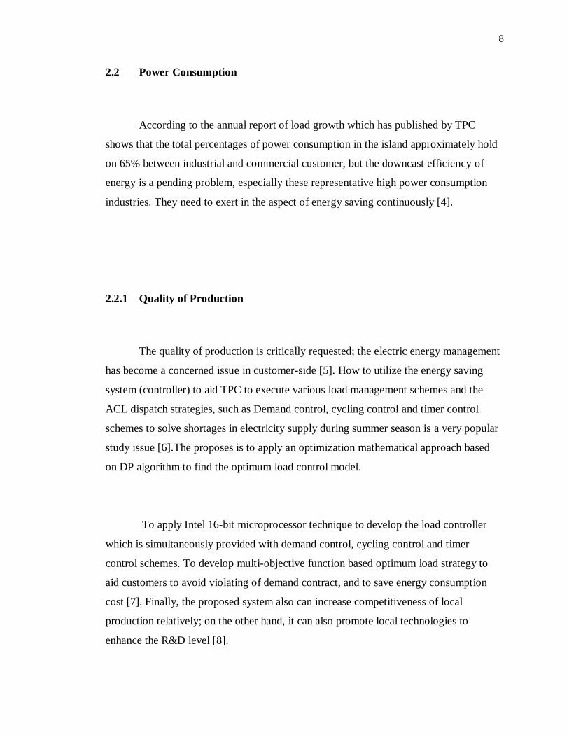
Figure 2.3: Result of conjoint analysis
8
2.2 Power Consumption
According to the annual report of load growth which has published by TPC
shows that the total percentages of power consumption in the island approximately hold
on 65% between industrial and commercial customer, but the downcast efficiency of
energy is a pending problem, especially these representative high power consumption
industries. They need to exert in the aspect of energy saving continuously [4].
2.2.1 Quality of Production
The quality of production is critically requested; the electric energy management
has become a concerned issue in customer-side [5]. How to utilize the energy saving
system (controller) to aid TPC to execute various load management schemes and the
ACL dispatch strategies, such as Demand control, cycling control and timer control
schemes to solve shortages in electricity supply during summer season is a very popular
study issue [6].The proposes is to apply an optimization mathematical approach based
on DP algorithm to find the optimum load control model.
To apply Intel 16-bit microprocessor technique to develop the load controller
which is simultaneously provided with demand control, cycling control and timer
control schemes. To develop multi-objective function based optimum load strategy to
aid customers to avoid violating of demand contract, and to save energy consumption
cost [7]. Finally, the proposed system also can increase competitiveness of local
production relatively; on the other hand, it can also promote local technologies to
enhance the R&D level [8].

9
2.3 Load Management
This paper is to investigate the potential of air conditioning load management by
solving the temperature sensitivity of load demand for various customer classes. The
load survey system has been applied to record the power consumption of sampling
customers in Taiwan Power Company (Tai power) for 4 years. The effect of the
temperature change to the customer power consumption is determined by executing the
statistic polynomial regression on the load survey results.
The increase of system power demand for each 1 C temperature rise is then
derived by integrating the load change of all customer classes. To verify the accuracy of
the simulation, the actual system power demand collected by Tai power EMS system is
applied to find the system load response to the temperature change. It is found that the
proposed methodology does provide an effective tool for the utility company to identify
the customer classes with good potential for air conditioner load management. Based on
this study, the load management programs of cooling energy storage system and direct
cycling control of air conditioners (A/C) are promoted by Tai power for the commercial
and residential customers respectively.
2.3.1 Economic
With the economic development in Taiwan, Tai power has experienced the
dramatic increase of system peak demand during recent years due to the usage of air
conditioners in various customer classes. The system peak demand has reached 23
830MWin 1998 and the annual growth rate of peak demand is 7.2% [9]. It is found that
10
the system peak demand has doubled its magnitude over the past 10 years and the
spinning reserve has dropped below the proper value for system reliable operation.
2.3.2 Industrial Customers
Although various interruptible load control programs [10] have been performed
in Tai power by offering incentive to the industrial customers with voluntary load
reduction, the service curtailment has to be applied when one of the large generation
units in Tai power trips. It has become a critical issue for Tai power to reduce the peak
demand by considering more effective load management strategies. However, with more
and more air conditioners used in the commercial, office and residential sections, the air
conditioner loading has contributed 35% of the total system peak demand.
The annual load growth by air conditioners is 353MWand it is increased by 15%
every year. With such a high percentage of air conditioner loading, the system load
demand of Tai power is increased by 490 MW when the temperature rises by 1 C. The
duty cycling control test of A/C units has been performed by many utilities [11] to
evaluate the power reduction and the impact on lifetime of A/C equipments.
To demonstrate the load management, the direct load control of A/C units has
also been included in the Tai power DAS project [12]. To enhance the load management
programs, the temperature sensitivity analysis of load demand for each customer class
has to be performed to identify the potential of peak demand reduction by the proper
design of air conditioning load management.
.
11
2.3.3 Power Consumption
The stratified sampling methodology [13] is used to determine the proper
customer size for the installation of intelligent meters so that the simulation results can
effectively represent the temperature sensitivity of power consumption for each
customer class. The power consumption of the test customers during each 15 minutes
interval is recorded and the sequential file of the customer power demand is created. The
polynomial regression analysis of the power consumption with respect to the
temperature is performed to solve the hourly temperature sensitivity of the customer
power consumption.
The temperature sensitivity of the actual system demand is then solved by
regression analysis to verify the previous integrated system power changes due to
temperature rise. After identifying the customer classes with high temperature
sensitivity, the field investigation of load composition with air conditioners can be
conducted and the potential of system peak demand reduction can be estimated. By
considering the avoided cost of generation capacity reduction by the air conditioning
load management, the incentive can be designed to promote the load management
programs of cooling energy storage system for the large commercial and office
customers with central air conditioners. The cycling control of window type air
conditioners can also be applied to the small commercial and residential customers.
Refer to figure 2.4, 2.5, 2.6 and 2.7.

12
Figure 2.4: the installation capacity, peak load and spinning reserve of Tai power.
Figure 2.5 the system peak load, average load and air conditioning load of Tai power.
Figure 2.6: Temperature sensitivity of various customer classes.

13
Figure 2.7: the power consumption increases due to 1 C temperature rise in Tai power
system.
2.4 Room Air Conditioner
Electrical home appliances go electronic rapidly these days. The needs for a
room air-conditioner to be met by electronic control techniques; seeds. The needs
include power saving, comfortableness, low noise, improved function, operation ability,
and reliability. With the conventional mechanical control system, it is difficult to
improve the comfortableness and operation ability, and therefore, emphasis has been laid
mainly on improvement of power consumption and noise characteristics.
In contrast to this, an electronic control introduced to a room air conditioner can
easily realize the following advantages: comfortableness due to finer then no static
setting, operation ability through feather touch operation and remote control, and
14
reliability by a motor lock protection circuit. To get the maximum effect from a room
air-conditioner equipped with an electronic control, the authors gave much thought to
optimum daily and yearly room air conditioner operating patterns. With them,
overcooling and overheating can be prevented, leading to simultaneous realization of
power saving and healthy comfortableness. Such control is beyond the reach of the
mechanical system, and this is an area where microprocessor control is most effective.
2.4.1 Comfortableness
Temperature, humidity, clothes, activity, wind velocity, and radiation heat (for
example, direct sunlight to human body) are closely related to the comfortableness.
However, inputting all of these factors to a room air-conditioner as control commands is
not practical due to sensory difference of each individual. Since humidity, wind velocity
and radiation heat are considered comparatively less variant in a room, these factors
have been excluded from the investigation this time.
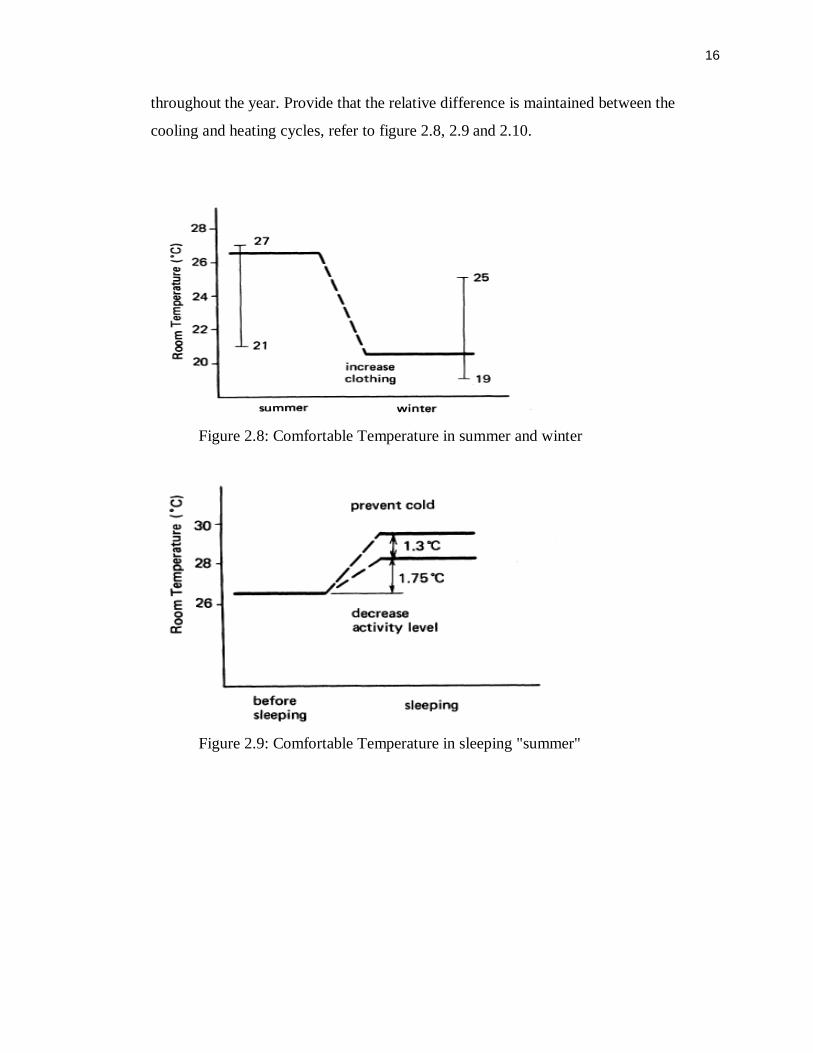
The comfortable temperature slightly differs with seasons, or depending on the
outside temperature, as follows: [14] 21-270C in summer and 19- 25°C in winter, if
relative humidity is 50%. Therefore, the comfortable temperature range is rather wide.
The center temperature in the thermostatic control differential is set at 26.50C in summer
and at 20.50C in winter. To be specific, if the room temperature is 26.5
0C or above when
the air-conditioner is turned on, it begins to cool, but if the room temperature is 20.50C
or below, it begins to heat the room, and if the room temperature is somewhere between
20.5 and 26.50C, it functions as a dehumidifier or circulating fan.
15
2.4.2 Comfortable Temperature
Let's consider the comfortable temperature during a sleep. Since human activity
is low while sleeping, it is desirable that the thermostat be set rather high to compensate
for the lowered activity level. If the setting were the same as that for daytime,
overcooling would result, adversely affecting the health of those who are sleeping,
especially children. If a man is assumed to be sitting in a chair quietly, his activity level
is 50 kcal/m2 hr and it falls to 35 kcal/m2 hr when he sleeps. To compensate for this
loss, the temperature must be raised by 1.750C, and to protect children from a chill or
cold caught in sleep, the temperature is further raised by approximately 1.30C.
2.4.3 Control Characteristics
From the foregoing consideration the optimum operating controls characteristics.
The upper curve is first explained here. The sleep timer is installed; until its set time the
air-conditioner has been operated to maintain 26.50C and thereafter the thermostatic
setting is raised by 30C. When the temperature drops by 1.5
0C at night even after the
cooling cycle stops, the control decides that the outside is cooler and causes the air-
conditioner to stop. In the winter heating cycle, the room temperature is maintained at
20.50C until time t1 and thereafter it is lowered by 5.5
0C.
When the temperature rises by 1.50C toward dawn after the heating cycle stops,
the control decides that the outside is warmer and causes the air-conditioner to stop. In
this manner, cooling, heating and dehumidifying cycles are automatically switched. This
prevents overcooling and overheating, or establishes a healthy, comfortable environment
16
throughout the year. Provide that the relative difference is maintained between the
cooling and heating cycles, refer to figure 2.8, 2.9 and 2.10.
Figure 2.8: Comfortable Temperature in summer and winter
Figure 2.9: Comfortable Temperature in sleeping "summer"

17
Figure 2.10: Optimum Characteristics of Temperature Control
2.5 Load Control
Population growth along with technological growth force the utility companies to
continue struggling to meet the ever increasing need for electricity. With the majority of
residents conforming to the 8 AM-5 PM work schedule, the utility companies experience
overwhelming demand peaks associated with a large amount of power being consumed
at the same time. Complementing this effect are periods of low demand.
Although over a period of time, the average amount of power consumed by a
community may be easily generated by a utility, that utility still has to provide enough
generation to meet its highest power demand peak. As this trend continues, utility
companies may inevitably adopt a real-time-pricing strategy, where customers will pay
more for the electric power they use during high demand periods and less during low
demand periods. It is in the best interest of the utility companies as well as the consumer
18
to try to reduce these high peak demand periods and level out their power demand
profiles as much as possible
2.5.1 Peak Demands
While reducing their peak demands, however, utilities will also need to compete
for new customers and keep current customers satisfied with their performance and
services. With the upcoming utility deregulation, customer satisfaction is crucial. Thus,
in such a business environment, any attempt to reduce the peak load of the system
requires the full support of customers. Any control scheme should consider an adequate
representation of the customers‟ specifications and preferences.
If a particular customer‟s comfort is not kept in mind during the implementation
of a control strategy, his or her tolerance level will decrease. Effectively, the customer‟s
willingness to participate in any peak reduction plan also decreases [15]. Not only will
unsatisfied customers fail to participate in a DLC program, they may likely choose to
purchase their power from another utility which is more supporting of the customers‟
desires and preferences in the deregulated energy market [16].

19
2.5.2 Peak Reduction
Traditionally, one way that the objective of a peak reduction plan has been
accomplished is by controlling residential electric water heaters and air conditioners.
The electric water heaters and air conditioners account for the largest contributors to the
total power consumption of a residence.
Furthermore, due to their energy storage capabilities, water heaters and air
conditioners are the ideal candidates for customer or utility demand-side management
(DSM) programs to shift part of the utility power demand from peak periods to off-peak
periods [17]. Such DSM strategies could be effective in utility peak load shaving and
valley filling, and therefore increasing the utility load factor. For this and other similar
reasons, electric water heaters and air conditioners have been the focus of many load
analysis and demand-side management studies, i.e. [18].
2.5.3 Parameters
Two parameters are used to quantify the preferences of each individual customer
in controlling their air conditioner. The first value is the ambient criterion, or a measure
of the internal building temperature that a customer prefers. In this work, the ambient
criterion is divided into two parameters: the actual temperature and the preferred
temperature of the customer.
With the available technology, it is feasible for a utility to monitor and report the
internal temperature of a building. The monitoring could either be conducted using a
20
separate sensor or possibly read from the thermostat of the building. The second
parameter is the comfort criteria. This is a measure of the range of temperatures that a
customer can tolerate. This gives the utility the possible advantage of longer off-times
and the customer the satisfaction of being comfortable during the cycling period. By
modeling these two parameters the customer will have a direct voice in the DLC
program.
2.5.4 Parameters
Along with the above two parameters chosen to model the customer preferences,
two more are determined to accurately model the thermal losses of a building. The two
parameters that have the most impact are the size of the building, and the overall
insulation rating of the building.
In [19], the insulation rating is related to the age of the house. This assumption
might have been valid 15-20 years ago, but it is not valid today. This is because due to
the increasing cost of new housing, many of the older homes that are in use have been
remodeled and reinsulated so they would no longer fit into this assumption. In this paper
the units for the domains of the thermal loss parameters are chosen to be square feet and
average BTU loss per square foot.
21
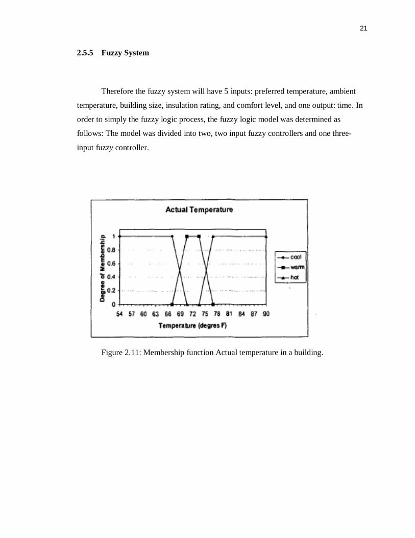
2.5.5 Fuzzy System
Therefore the fuzzy system will have 5 inputs: preferred temperature, ambient
temperature, building size, insulation rating, and comfort level, and one output: time. In
order to simply the fuzzy logic process, the fuzzy logic model was determined as
follows: The model was divided into two, two input fuzzy controllers and one three-
input fuzzy controller.
Figure 2.11: Membership function Actual temperature in a building.
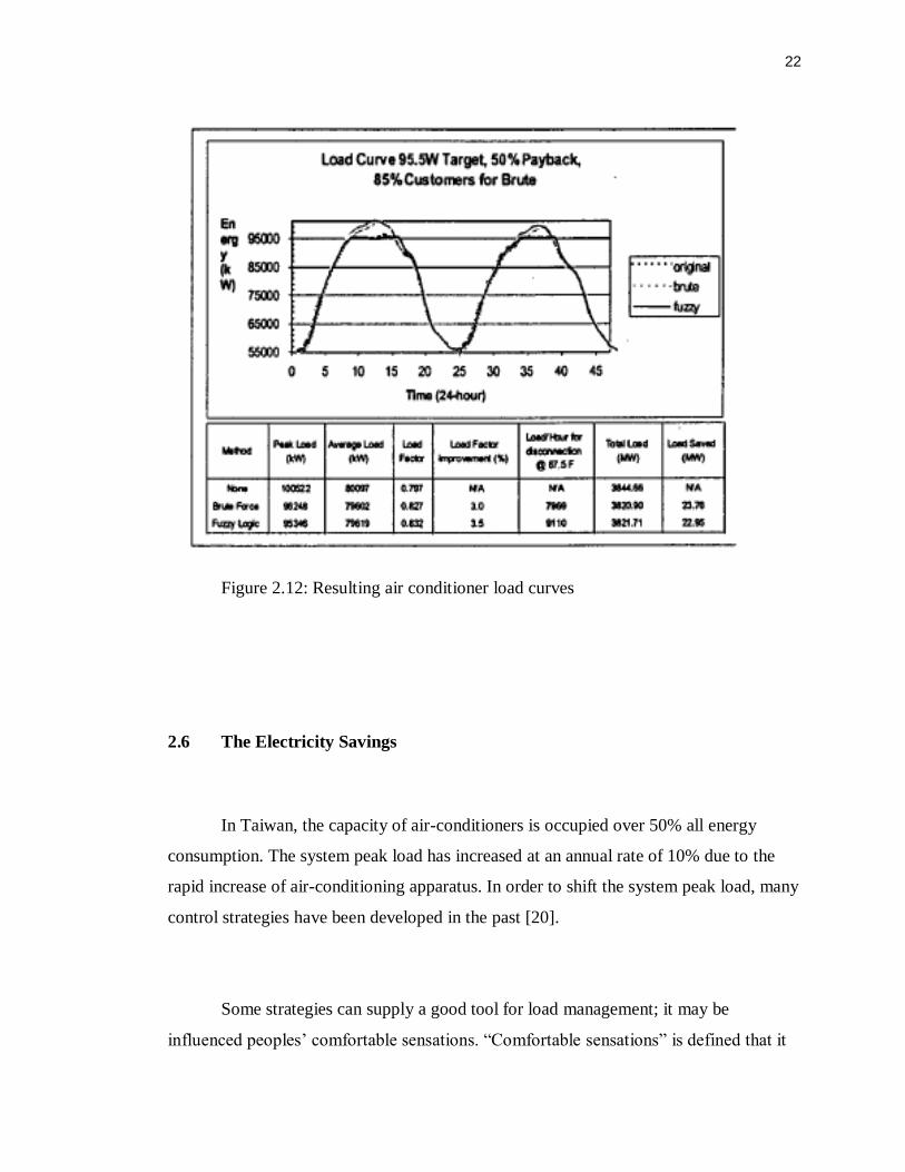
22
Figure 2.12: Resulting air conditioner load curves
2.6 The Electricity Savings
In Taiwan, the capacity of air-conditioners is occupied over 50% all energy
consumption. The system peak load has increased at an annual rate of 10% due to the
rapid increase of air-conditioning apparatus. In order to shift the system peak load, many
control strategies have been developed in the past [20].
Some strategies can supply a good tool for load management; it may be
influenced peoples‟ comfortable sensations. “Comfortable sensations” is defined that it

23
will be produce the acceptable thermal environment to 80% or more of the occupants
within a space. It will play an important role for performing the control of air-
conditioners in future [21]. The thermal control of air-conditions is required for
maintaining comfort and saving energy. It is recommended that electric utilities or users
use this technology as a demand side management strategy for reducing energy
consumption.
2.6.1 Thermodynamics
The first law of thermodynamics states that the amount of energy in any
thermodynamic system is constant. The heat-balanced model is taken from the indoor
environment due to the use of air-conditioners. The microclimate change including
temperature and humidity immediately affects the energy exchange. When the
temperature/humidity of the body is greater than that of its surroundings, it will be
operated to keep the comfortable environment. Either cooling or humidifying process
must be dissipated the electrical energy. To effectively reduce the electrical energy
dissipated, a tool with PNN is proposed for reaching the goal
2.6.2 Application
In recent years, many successful applications on air-conditioner load control [22]
have been reported to evaluate the power reduction. The ON/OFF operation of air-
conditioners will impact on lifetime of equipments and it will produce the huge starting
current. Some techniques [23], such as variable frequency control (VFC) of air-
24
conditioners have been developed to reach the saving energy. Although the effect of
saving energy by VFC is obvious in industrial applications, it is worthwhile to pay
attention to the peoples‟ comfortable sensation.
The use of Back-Propagation(BP) network, which was proposed for reaching
thermal comfort and saving energy of HVAC, was time consuming and very slow
without guaranteed global minimum. Probabilistic neural network (PNN) [24] was thus
studied and proposed in this paper. PNN lies in its ability to model a multi-input/multi-
output (MIMO) system without making complex dependency assumptions among inputs
and outputs. It is easy to avoid the model‟s becoming “black box” due to the large scale
of network caused by a number of input variables.
The advantages of PNN include very fast learning and recalling process, no
iteration for weight regulations in learning process, no pre-decision for the number of
hidden layers and the number of hidden nodes in each layer, and adaptability for
architecture changes.
2.6.3 Electrical Energy Management
This paper presents an effective tool for Electrical Energy Management (EEM)
of PNN. An analysis conducts a practical air-conditioner with the electromagnetic valves
and a variable speed compressor. PNN performance, which acquires information of
EEM from the field test, is analyzed with the room temperature, room humidity,
saturated vapor pressure, and air vapor pressure. By using the training data, PNN can
automatically carry out the compressor operating frequency and the status of
electromagnetic valves to obtain a suitable operation point without affecting the comfort