automated core sample handling for future … · automated core sample handling for future mars...
TRANSCRIPT

1
AUTOMATED CORE SAMPLE HANDLING FOR FUTURE MARS DRILL MISSIONS
Alois Winterholler, Matt Roman, David P. Miller, Jorg Krause, and Tim Hunt
University of Oklahoma, 865 Asp Ave, Rm 212, Norman OK 73019, USA;[email protected], [email protected], [email protected], [email protected] & [email protected]
ABSTRACT
Signs of microbial life on Mars, if they exist, will prob-ably exist underground. This paper describes a roboticssystem for handling and sub-sampling cores taken froma robotic drill. The system prepares samples for analysisand life detection experiments. This system has been in-tegrated with a drill and other instruments and tested inthe field. This paper presents a description of the systemand observations from the field test.
Key words: sample handling, Mars drill.
1. INTRODUCTION
The MARTE project (Mars Astrobiology Research andTechnology Experiment) is part of NASA’s ASTEP astro-biology technology development program. This projectexplores the science, instrumentation and automation is-sues in performing a deep (10s of meters) drill operationon Mars, using Rio Tinto Spain as an analog drill site[1, 8, 9]. There are five major pieces to the MARTE sys-tem: 1) The Drill Core Service Module (DCSM) beingbuilt by NASA Ames serves as the mechanical integra-tion platform for all other subsystems; 2) the Drill sys-tem being built by Honeybee Robotics will perform theactual drilling and will remove a 27 mm diameter, 25 cmlong core every quarter meter that it drills; 3) the Bore-Hole-Inspection System or BHIS (built by CAB [2] inMadrid) will be lowered periodically into the hole to ex-amine the walls geological possible biological inspection;4) the various science instrumentation that will inspectthe cores and selected sub-samples taken from the cores;and 5) the Core Sample Handling System (CSHS), whichis the subject of this paper.
2. THE MARTE CSHS
The Core Storage and Handling System (Figure 1) con-sists of several robotic devices. The CSHS receives a core
Figure 1. The elements of the CSHS before being inte-grated to the rest of the MARTE system
from the drill system into the Core Clamp which is a 24DoF gripper designed to hold tightly onto a core whichcan be anything from a 27 mm diameter 25 cm rod ofsolid rock to a pile of chips and gravel. Depending onthe consistency of the core, it may be run under a Fac-ing Saw; whose feed rate is autonomously adjusted bythe required cutting force for the material at hand. Thefaced sample is then run under a set of remote scienceinstruments. Finally the core is placed into a random ac-cess storage system capable of storing 2.25 m of core (oralmost three days of drilling). This storage provides thescience team with time to analyze data and decide whichif any cores should be subjected to sub-sampling for moredetailed biological analysis.
If sub-sampling is desired then the effected core isbrought out of storage, and an 18 mm segment of the coresurrounding the spot of science interest is removed bythe Sub-sampling Saw. This sub-piece of the core is thencrushed to powder, sifted, and inserted into the SOLID(see [2]) life detection instrument.
The remainder of this paper will describe the pieces ofthe CSHS and the results from our preliminary field testat Bonny Doons Quarry in Santa Cruz California.
2
2.1. Core Clamps
The CSHS is equipped with nine Core Clamps (see Fig-ure 2). The Core Clamps serve as fixtures for the retrievedsubsurface core samples. The Core Clamps hold the coresamples during the sample preparation and maintain a de-fined position while the different scientific instrumentsexamine and analyze samples.
Figure 2. CAD Model of a Core Clamp
The core sample is transferred and placed into the CoreClamp by the Core Sample Hand Off Mechanism. Amotor mounted to the Linear Rail Cart closes and opensthe Core Clamp. The Core Clamp is symmetric to thelongitudinal axis. Each side consists of a bar whichholds 12 fingers. The ends of the bar are supported bythreaded shafts. The four threaded shafts are simultane-ously driven by a central drive shaft via bevel gears. Theclamping force is applied to the sample with the concaveshaped fingers. The individual spring loaded fingers com-ply with irregular shaped and fractured samples. This as-sures a good grip on the core even if it is fragmented intoseveral pieces. In addition, the spaces between the fin-gers enable the Sub-sampling System to cut through andremove a disc shaped sub-sample (see Figures 10 and 11).
The bottom side of the Core Clamp incorporates a lock-ing mechanism. The locking mechanism provides a rigidconnection while the Core Clamp is on the Linear RailCart.
2.2. Linear Rail and Cart
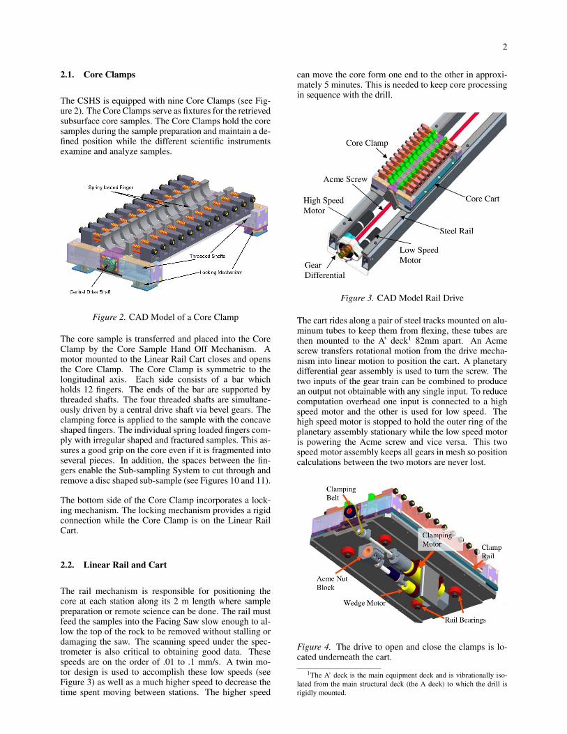
The rail mechanism is responsible for positioning thecore at each station along its 2 m length where samplepreparation or remote science can be done. The rail mustfeed the samples into the Facing Saw slow enough to al-low the top of the rock to be removed without stalling ordamaging the saw. The scanning speed under the spec-trometer is also critical to obtaining good data. Thesespeeds are on the order of .01 to .1 mm/s. A twin mo-tor design is used to accomplish these low speeds (seeFigure 3) as well as a much higher speed to decrease thetime spent moving between stations. The higher speed
can move the core form one end to the other in approxi-mately 5 minutes. This is needed to keep core processingin sequence with the drill.
Figure 3. CAD Model Rail Drive
The cart rides along a pair of steel tracks mounted on alu-minum tubes to keep them from flexing, these tubes arethen mounted to the A’ deck1 82mm apart. An Acmescrew transfers rotational motion from the drive mecha-nism into linear motion to position the cart. A planetarydifferential gear assembly is used to turn the screw. Thetwo inputs of the gear train can be combined to producean output not obtainable with any single input. To reducecomputation overhead one input is connected to a highspeed motor and the other is used for low speed. Thehigh speed motor is stopped to hold the outer ring of theplanetary assembly stationary while the low speed motoris powering the Acme screw and vice versa. This twospeed motor assembly keeps all gears in mesh so positioncalculations between the two motors are never lost.
Figure 4. The drive to open and close the clamps is lo-cated underneath the cart.
1The A’ deck is the main equipment deck and is vibrationally iso-lated from the main structural deck (the A deck) to which the drill isrigidly mounted.

3
Each Core Clamp is moved between stations on theCSHS by the cart actuated from the Linear Rail. The un-der side of the cart includes a mechanism to open andclose the clamp, to release the clamp from the StorageComb, Linear Rail bearings, and Acme nut blocks. AnHD systems dc motor and 80:1 harmonic drive speed re-ducer drives the clamping belt (Figure 4). The large pul-ley on this belt mechanism has a grooved socket to allowthe spring loaded shaft on each clamp to mate with it (seeFigure 4). This way the coupling does not have to bealigned prior to mating the clamp to the cart and torquecan be applied to each clamp after it has been put ontothe cart.
The two sides of the cart have elevated rails that guidethe cart into position when being loaded from the StorageComb; they hold the cart in place during sub-samplingand facing operations. The wedge motor (see Figure 5) isused to release the clamp from the cart while it is beingstored. A small wedge is moved back by another minia-ture screw mechanism on the under side of the cart. Thiswedge pushes a lever on the bottom of the clamp upwardto disengage the locking mechanism.
Figure 5. The wedge pushes a lever on the bottom of theclamp to unlock the clamp from the cart.
2.3. Core Storage System
The Core Storage System provides the capability to holdon to interesting core samples and retrieve them to dofurther analysis. In addition, the Core Storage System isused to dispose of core samples after scientific investiga-tions are completed. The Core Storage System consists oftwo main components: The stationary Circular Rail andthe rotating Storage Comb. The circular shape was em-ployed to most effectively fit on to the hexagonal landermock up. The rail section expands about two thirds of afull circle and is mounted to the main equipment deck.The structural design is selected in order to maximize thestiffness and minimize the deflection due to flexural de-formation in the main equipment deck. The middle of theCircular Rail provides a mounting interface for the CombRotation Assembly. Furthermore, the Linear Rail is alsomounted to the base plate of the Comb Rotation Assem-bly. This arrangement ensures proper alignment betweenthe Core Storage System and the Linear Rail.
Figure 6. The Storage Comb can store 9 cores and dis-pose of extra ones.
The Storage Comb consists of nine rigid mounted forksand one fork pivoted at the comb frame (Figure 6). Thecomb rotation is done by a flexible rack and pinion driveand the position is determined by switch and notch com-bination. The Storage Comb holds a maximum of nineCore Clamps during nominal operation. In order to per-form clamp swap and core disposal operations one clampstorage spot has to be unused. A Core Clamp exchangeis performed by unlocking the Core Clamp from the Lin-ear Rail Cart and simultaneously locking it to the CoreStorage System. The Linear Rail Cart is pulled out un-derneath while the Core Clamp rests on the Core StorageSystem (see Figure 7).
Figure 7. The sequence for moving a clamp onto the stor-age rail.
The sequence to dispose a no longer needed core samplestarts with moving the opened Core Clamp to the CoreDisposal Mechanism on the counterclockwise end of theStorage Comb. A powerscrew linkage mechanism rotatesthe pivoted storage fork to the lander outside where thecore sample slides of the Core Clamp and falls to theground.
2.4. Facing Saw
The Facing Saw removes the external surface of the coresample along its length (Figure 8). This is done to achievea clean planar surface that will be a standard height forall imaging and spectrometer readings. A dry cutting dia-

4
mond encrusted masonry blade with a discontinuous cir-cumference to allow better chip removal is lowered intoposition approximately 5mm from the top of the CoreClamp. The blade is 150mm in diameter and 2.6mmthick. It is powered by a 12V DC motor with a 2.5:1bevel gear reduction which can be retracted out of thepath of the cart in the event that an unconsolidated core isrecovered. In this case the core cannot be safely faced sothe saw is lifted out of the way.
The retraction mechanism is designed into the main bodyof the saw. The retraction motor drives a 100:1 wormgear connected to a pinion shaft. The pinion rides on acurved gear rack producing the rotating motion about theretract pivot point (Figure 9).
Figure 8. The Facing Saw shaving the top off of a core
Figure 9. CAD Model of the Facing Saw
2.5. Sub-sampling System
Each rock sample taken by the drill is scanned by theremote instruments then placed on the Storage Comb. Ifthe data shows that a particular segment of the core is
of special interest then a sub-sample of that area can betaken.
Figure 10. The Sub-sampler cuts through a core
The sub-sampling system uses twin saw blades paral-lel to each other to cut perpendicular to the axis of thecore sample (Figure 10). Once through the sample theblades stop then squeeze together to pick up the rockleft between them (Figure 11). Both 100mm diameterblades are driven from the same motor. The blade mo-tor drives a shaft with extra wide pulleys on both ends toallow the belt to move laterally when the arms squeeze to-gether. The arms are supported by two smooth shafts thatkeep them parallel while a turnbuckle screw provides thesqueezing motion (Figure 12). The blades can be opened39mm and close on a sample as narrow as 14mm wide(the width of a clamp finger). The standard size of asample is approximately 17mm; that is 20mm spacingbetween blade centers and about 3mm lost to cuttings.The vertical motion of the saw is accomplished by a ball-screw mechanism encased in an aluminum frame to keepout debris.
2.6. Crushing and Sample Transfer
Once a segment from the core has been extracted by thesub-sample saw, it must be prepared for insertion into theSOLID instrument. SOLID requires 0.75 ml of powder ofa grain size of 500µm or smaller. To reduce the core ma-terial to this particle size we use a minature rock crusher

5
Figure 11. The two blades of the Sub-sampler squeezetogether to lift out an 18mm segment of the core
Figure 12. The inner workings of the Sub-sampler saw
developed at JPL [4]. This crusher produces particles ofwhich only about 40% are the correct size – the remain-der being too large [3].
To eliminate the oversized particles the CSHS employsa simple sieve (Figure 13). A small vibrator motor isused to help sift the particles through the sieve and ontoa chute.
The chute leads down to a core transfer tube. This tube(Figure 14) has a small funnel and some fill holes. Thechute touches the funnel causing it to vibrate as well andthe small rock particles stream into the funnel, throughthe holes and into the tube. The tube has a plug on thebottom which can be opened by pressing on the spring-loaded stem at the tube’s top. A spring-loaded rack holds13 tubes in place. When a tube is removed, a solenoidcan be fired which moves a release allowing the next tubeto slide into place under the crusher.
Figure 13. The crusher drops rock fragments onto thesieve which allows particles ≤ 0.4mm to pass through (inthis case into a sterile collection bag), and dumps largerfragments into the waste cup.
The sub-sample Transfer Arm is used to move the SampleTubes full of crushed rock from the tube array and insertit into SOLID. The arm is mounted on an identical rota-tional/vertical actuation base as the Sub-sampler (Figure15). It uses a solenoid actuated fist that slides opens onceit moves into position to pick up a full tube. The solenoidis released and the fist is held closed by a return spring.The tube can then be lifted and rotated over the SOLIDinstrument. When it is positioned correctly the lower halfof the Sample Tube is lowered into a split gasket sealedopening on top of SOLID. The hammer motor is turnedon to release the contents of the tube. The motor spins acrank that is connected to a hammer which depresses thespring loaded seal on the bottom of the tube.
Figure 14. A Sample Tube (minus funnel). The cap isdepressed, opening the drain on the far end. Holes nearthe left end allow powder to enter from the sieve.
2.7. Control Electronics
The MARTE system is controlled through an executivesystem. This in turn sends serial commands to the CSHSreal-time controllers. The CSHS has 18 powered actua-tors and about twice that many sensors. Most of the ac-tuators need to run under PID position control, some run

6
Figure 15. The Transfer Arm mounted on the verticalactuator and its rotational base.
Figure 16. The Sub-sampler is in the position where itdropped the core segment into the crusher. The samplehas been crushed and fed into a Sample Tube which isgripped by the Transfer Arm on its way to be insertedinto the mockup of the SOLID life detection instrument.
under PID speed control and some operate at set PWMrates. There are a few that do some operations under onecontrol regime and other parts of their operations undera different control scheme. To get the high positional ac-curacy and repeatability, and maintain the flexibility re-quired, we used a custom controller that was a modifica-tion of the XBC robot controller [7, 6]. This controllermakes use of a 100K gate FPGA which handles the PIDand PWM control along with the digital inputs from thesensors. The FPGA is controlled by an ARM 7 CPU. TheCPU and LCD screen for the controller are contained in aCOTS Nintendo GBA. The FPGA board with its daughterboard that contains all of the motor drivers [5], connectthrough the game port slot on the GBA. This system runsthrough the control loop at about 200HZ.
Figure 17. The two control computers and cabling lead-ing to the various components
Each controller can drive up to ten motors each with ahigh resolution quadrature encoder. Each controller canalso read 19 digital ports and 8 analog ports. The con-troller box contains two of these controllers and is shownin Figure 17.
On high precision mechanical parts such as the Lin-ear Rail or the positioning of the Sub-sampler, the en-coder resolution maps to about 1µm per encoder tic.The position control allows cutting speeds as slow as50µm/second. The positioning accuracies and repeata-bility are better than 50µm for most of the actuators.This level of control is most needed during sub samplingwhere an error of 0.25mm can result in sub-samplingthe clamp materials in addition to the rock cores. Thespeed control is used to ensure safe cutting without let-ting this already time consuming process grow longer.PWM control is used when closing the clamps and dock-ing clamps to the storage system. This provides a nearconstant torque, but will avoid over tightening the clampsor potential damage should something be misaligned inthe storage rail.
3. SYSTEM PERFORMANCE & FUTURE WORK
After several weeks of laboratory testing, in June of 2005the MARTE system was deployed for its first field test(Figure 18) at a quarry near Santa Cruz, CA in the USA.The goal of this preliminary test was to exercise all as-pects of the various MARTE systems and run through atleast one full drill cycle. During the week of testing, twovery unseasonable rain storms hit the area, dropping sev-

7
eral cm of rain at the test site and turning the dirt surfaceinto a quagmire. Testing was temporarily halted and allpersonnel spent their time covering equipment and dig-ging trenches to keep the bore-hole from flooding.
Despite the environmental challenges, a bore-hole over1.3 m in depth was drilled and the core was processed bythe CSHS. Additionally, several test cores – some sterileand some laced with e-coli, were processed by the CSHSto provide data for cross-contamination studies.
The CSHS system worked very well, though a minor re-design was indicated for the Sample Tube feeder. Whileonly minor rework and optimizations are planned beforethe more extensive September field test in Rio Tinto, sev-eral items did appear that would need to be addressed be-fore an actual flight mission could take place.
Perhaps the most critical is finding some method for mea-suring the amount of sample powder produced by thecrusher. We found that the 40% production rate predictedby [3] is very rock dependent. This could vary either wayby more than a factor of 2 depending on the particularchunk being processed. Crushing time also appeared tovary by up to a factor of 4 depending on the orientationat which the rock sample came to rest inside the crushergullet – some orientations causing the sample to fractureimmediately, others taking upwards of an hour before thefirst powder started to appear.
These changes in crushing speed and output are criticalbecause they preclude an open loop method of filling theSample Tube. Over filling the tube causes the powder topack and makes it difficult to release into SOLID. Un-der filling the tube does not provide sufficient material toSOLID to get a satisfactory analysis.
Another issue that needs to be addressed in future workis dust containment. Dust from cuttings and crushingcauses cross contamination as well as potentially degrad-ing equipment and instruments. We currently use a vac-uum system to remove the cuttings from the sub-samplesaw. We will install a similar system for the Facing Saw.There is some debate whether or not such a vacuum sys-tem could be used on Mars. However, tests describedin [10] appear to indicate that pressure ratios in air flowrather than the absolute differential are the critical mea-sure for floating cuttings on air. This may mean that vac-uum systems for containing dust and cuttings will in factbe practical on Mars.
Experiments in Spain this Fall will be a more thoroughtest of the CSHS and the rest of the MARTE system. Butthis preliminary field experiment has validated the CSHSas a highly automated reliable method for cleanly han-dling rock cores and powder samples.
ACKNOWLEDGMENT
The authors wish to thank Rich LeGrand of CharmedLabs, Kyle Machulis of KISS Institute for Practical
Figure 18. The MARTE system lands at Bonny Doonquarry.
Robotics, Howard Cannon, Scott Christa and Mark Bran-son of Ames Research for their help with the control elec-tronics and software. This work was supported in part bya contract from NASA Ames Research Center.
REFERENCES
[1] John Bluck. NASA scientists to drill fornew, exotic life near acidic Spanish river.http://amesnews.arc.nasa.gov/releases/2003/03 24AR.html, 2003.
[2] CAB. Centro de Astrobiologıa. http://dalbe.inta.es/, 2005.
[3] S. J. Chipera, D. T. Vaniman, D. L. Bish, P. Sarrazin,S. Feldman, D. F. Blake, G. Bearman, , and Y. Bar-Cohen. Evaluation of rock powdering methods toobtain fine-grained samples for chemin, a combinedxrd/xrf instrument. In Abstracts from 2004 Lunar& Planetary Science Conference. Lunar PlanetaryInstitute, 2004.
[4] Candice J. Hansen and David A. Paige. SPADE:A rock crushing and sample handling system devel-oped for mars missions12. In Abstracts from Lunar& Planetary Science XXXIV. LPSC, 2003.
[5] Acroname Inc. 3A back EMF H-Bridge.http://www.acroname.com/robotics/parts/S11-3A-EMF-HBRIDGE.html, 2004.
[6] Richard LeGrand. Xport 2.0 user guide.http://www.charmedlabs.com/xport-user-guide.pdf, 2003.
[7] Richard LeGrand, Kyle Machulis, David P. Miller,Randy Sargent, and Anne Wright. The XBC: amodern low-cost mobile robot controller. In Pro-ceedings of IROS 2005. IEEE Press, August 2005.
[8] C. Stoker, L. Lemke, H. Mandell, D. McKay,J. George, J. Gomez-Alvera, R. Amils, T. Stevens,and D.P. Miller. Mars analog research and tech-nology experiment (MARTE): A simulated Mars

8
drilling mission to search for subsurface life at theRio Tinto, Spain. In Abstracts from 34th Lunar &Planetary Science Conference. LPI, March 2003.
[9] C. R. Stoker, L.G. Lemke, H. Cannon, B. Glass,S. Dunagan, J. Zavaleta, D. P. Miller, and J. Gomez-Elvira. Field simulation of a drilling mission to marsto search for subsurface life. In Abstracts from 2005Lunar & Planetary Science Conference, 2005.
[10] K. A. Zacny, M. C. Quayle, and G. A. Cooper.Enhancing cuttings removal with gas blasts whiledrilling on mars. Journal of Geophysical Research,110(E04002), April 2005.