author(s) yoon, sang il. title monterey, california. naval
TRANSCRIPT

This document was downloaded on May 04, 2015 at 23:45:26
Author(s) Yoon, Sang Il.
Title Definition study and model for a tethered sounding rocket.
Publisher Monterey, California. Naval Postgraduate School
Issue Date 1988
URL http://hdl.handle.net/10945/23008


NAVAL POSTGRADUATE SCHOOLMonterey, California
V -6 >1^-S
DEFINITION STUDY AND MODEL FORA TETHERED SOUNDING ROCKET
by
Yoon, Sang 11
December 1988
Thesis Adviser: Richard C. Olsen
Approved for public release; distribution is unlimited
T242452


Unclassified.UHIIY CLASSIFICATION OF fHIS PAGE
REPORT DOCUMENTATION PAGEREPORT SECUHIIY CLASSIFICA llOt^
Unclassifiedlb RESTRICTIVE MARKINGS
SECURITY CLASSIFICATION AUIHOHIIY
DECLASSIFICATION /DOWNGRADING SCHEDULE
3 DISTRIBUTION/AVAILABILITY OF REPORT
Approved for public release;
distribution is unlimited
PERFORMING ORGANIZATION REPORT NUMBER(S) 5. MONITORING ORGANIZATION REPORT NUMBER(S)
NAME OF PERFORMING ORGANIZATION
Naval Postgraduate School
6b. OFFICE SYMBOL{If applicsble)
61 •
;a. NAME OF MONITORING ORGANIZATION
Naval Postgraduate School
ADDRESS {City, State, and ZIP Code)
Monterey, California 93943-5000
7b. ADDRESS (City. State, and ZIP Code)
Monterey, California 93943-5000
NAME OF FUNDING /SPONSORINGORGANIZATION
8b. OFFICE SYMBOL{If applKable)
9. PROCUREMENT INSTRUMENT IDENTIFICATION NUMBER
ADDRESS (City, State, and ZIP Code) 10. SOURCE OF FUNDING NUMBERS
PROGRAMELEMENT NO.
PROJECTNO.
TASKNO.
WORK UNITACCESSION NO.
TITLE (Include Security Clamlication)
Definition Study and Model for a Tethered Sounding Rocket
PERSONAL AUTHOR{S)
I. TYPE OF REPORTMaster's Thesis
13b TIME COVEREDFROM TO
14. DATE OF REPORT (Year. Month, Day)
1988 December15 PAGE COUNT
109
SUPPLEMENTARY NOTATIONThe views expressed in this thesis are those of the author and do not
fleet the official policy or position of the Department of Defense or the U. S. Government
COSATI CODES
FIELD GROUP SUB-GROUP
18. SUBJECT TERMS (Continue on reverse if necessary and identify by block number)
Tether deployment system, Plasma contactor Hollow Cathode,
Flight program, Model of system electrodynamic behavior study
t ABSTRACT {Continue on reverse if i^ecessary and identify by block number)
l„.„„.„_„.... .,...„,.,.„,„„,„...,..„„.,.,...\) [roin a satellite into the ambient plasma, and llie return patli through the plasma. The devices to be
jseJ to establish electrical contact with the plasma are hollow cathode plasma sources, using Xenon
Hopeilent. Two satellite sections will be connected by a l()()-m cable, which can be used to bias the two
satellites with respect to each other. The current through the connecting cable will be monitored, along
kvith the particle fluxes to the satellites. A fiber-optic technique will be used to measure the return
:urrent flowing through the ambient plasma. Electric fields, densities, and plasma waves will be
iionitored with floating probes. We intend to launch this payload from Wallops Flight Facility two years
ilter funding begins.
IDISTRIBUTION/AVAILABILITY OF ABSTRACT
El UNCLASSIFIED/UNLIMITED SAME AS RPT DTIC USERS
21. ABSTRACT SECURITY CLASSIFICATIONUnclassified
;». NAME OF RESPONSIBLE INDIVIDUAL
Professor Richard Christopher Olsen22b TELEPHONE {Include Area Code)
(408) 646 - 201922c. OFFICE SYMBOL
61 Os
l>FORM1473,8nMAR 83 APR edition may be uied until exhausted
All other editionj are obsoleteSECURITY CLASSIFICATION OF THIS PAGE
A U.S. 0«>ifnm«nl Prlnllni onicd Ifit—•Ot-143
Unclassified
Approved for public release; distribution is unlimited.
Definition Study and Model for a TetheredSounding Rocket
by
Yoon, ^ang II
Major, Republic of Korea ArmyB.S., Republic of Korea Military Academy, 1979
Submitted in partial fulfillment of the
requirements for the degree of
MASTER OF SCIENCE IN PHYSICS
from the
NAVAL POSTGRADUATE SCHOOLDecember 1988
ABSTRACT
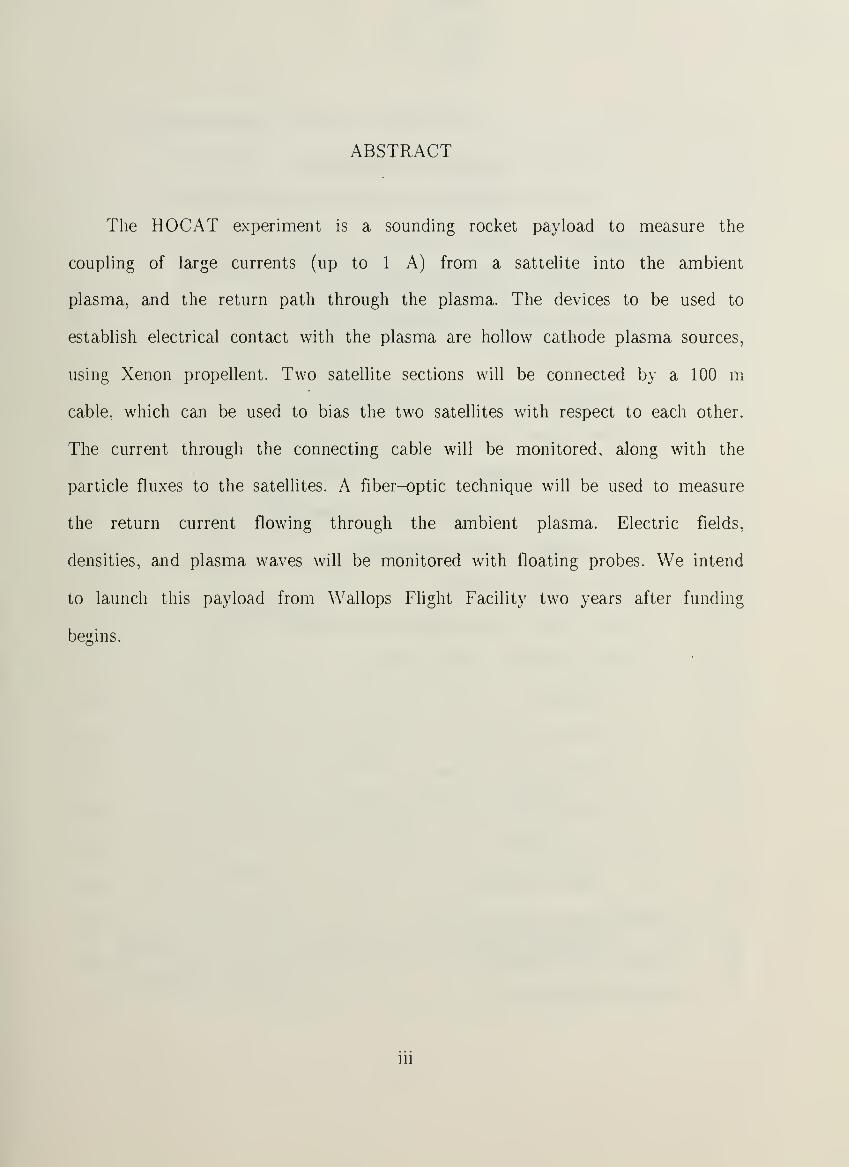
The HOCAT experiment is a sounding rocket payload to measure the
coupling of large currents (up to 1 A) from a sattelite into the ambient
plasma, and the return path through the plasma. The devices to be used to
establish electrical contact with the plasma are hollow cathode plasma sources,
using Xenon propellent. Two satellite sections will be connected by a 100 m
cable, which can be used to bias the two satellites with respect to each other.
The current through the connecting cable will be monitored, along with the
particle fluxes to the satellites. A fiber-optic technique will be used to measure
the return current flowing through the ambient plasma. Electric fields,
densities, and plasma waves will be monitored with floating probes. We intend
to launch this payload from Wallops Flight Facility two years after funding
begins.
ni

TABLE OF CONTENTS
I. INTRODUCTION 1
A. A HISTORY OF TETHER CONCEPTS 1
B. ELECTRODYNAMIC TETHERS 6
1
.
Basic Concept 6
2. Electrodynamic Tether Applications 7
3. Tether Experiments 8
a. Tethered Satellite System-1 Experiment 8
b. US-JAPAN Charge Rocket Experiment 10
c. MAINHK Rocket Experiment 11
C. PLASMA CONTACTORS 13
1. Basic Concept (Requirements and Future Mission) 13
2. Plasma Contactor Flight History 15
a. Balloons 15
b. Electron Gun 17
c. Neutral Gas Releases 18
d. Ion Beams 20
e. Ion Engine 21
f. Hollow Cathodes- •• 29
D. PROPOSED EXPERIMENT 30
H. TETHER DEPLOYMENT 31
A. BASIC DYNAMICS 31
IV

B. HOCAT DEPLOYMENT OBJECTIVES 32
1. US-JAPAN Joint Experiment Deployment System 34
2. MAIMIK Rocket Experiment Deployment System 38
3. CANADIAN OEDIPUS Experiment Deployment System 39
4. Tethered Satellite System-1 Deployment System 42
III. PLASMA CONTACTOR HOLLOW CATHODES 43
A. LABORATORY STUDIES 43
B. THEORETICAL STUDIES 50
C. FLIGHT EXPERIMENT DATA 52
IV. EXPERIMENTAL FLIGHT PROGRAM 54
A. ENVIRONMENT 54
B. LAUNCH VEHICLE 60
C. DEPLOYMENT SYSTEM 62
D. FLIGHT SCENARIO 63
E. PAYLOAD • • 63
1. Hollow Cathode 64
2. Experiment Control and PCM Encoder 65
3. Electric Field Instruments 66
4. Thermal Plasma Analyzer (Ions and Electrons) 67
5. Direct Current Measurements (Current Loop) 71
6. TV Camera 73
7. Magnetometer 74
V. MODEL OF SYSTEM ELECTRODYNAMIC BEHAVIOR 75
A. PROBE THEORY 75

B. MODIFICATIONS DUE TO PLASMA CONTACTOR 86
1. Electron Emission 86
2. Election Collection 87
C. SUMMARY 89
VI. CONCLUSIONS AND RECOMMENDATIONS 90
LIST OF REFERENCES 92
INITIAL DISTRIBUTION LIST 97
VI

Fig. 1.1
Fig. 1.2
Fig. 1.3
Fig. 1.4
Fig. 1.5
Fig. 1.6
Fig. 1.7
Fig. 1.8
Fig. 1.9
Fig. 1.10
Fig. 1.11
Fig. 1.12
Fig. 1.1.3
Fig. 1.14
Fig. 1.15
Fig. 1.16
Fig. 2.1
Fig. 2.2
Fig. 2.3
Fig. 2.4
Fig. 2.5
Fig. 2.6
Fig. 2.7
LIST OF FIGURES
Gemini-Titan Space Vehicle Configuration 2
Agena Target Vehicle Configuration 3
Gemini Spacecraft 3
Tethered Spacecraft/Target Vehicle 3
Effect of Damping on the Oscillation of Tethered System-
•
4
Effect of Relative Velocity on Motion of Gravity-Grad- • • • 5
Electrodynamic Tether System 7
TSS-1 Satellite System 9
Payload Configuration of fourth TPE Experiment 11
Individual Liquid Metal Ion Emitter 14
Collector Screen in the Deployed Configuration 16
Configuration of ATS-5 Ion Thruster 22
Configuration of ATS-6 Ion Engine 23
Spacecraft Plasma Current Diagram of SERT-II 26
Distribution of Emission Currents 27
Excess Neutralizer Emission 28
Dumbbell Tether Model 31
Hollow Cathode Configuration 33
Plot of Tether Wire Extension Velocity vs Time 36
Plot of Tether Separation Distance vs Time 37
Deployment Velocity of fourth US-JAPAN Experiment 38
Plot of Separation Velocity vs Time 40
Plot of Separation Distance vs Time 41
Vll
TSS-1 Reel and Boom Mechanism 42
Perturbing Effect of Vacuum Tank Wall 45
Contactor Anode-to Ambient Plasma Potential Difference
vs Electron Emission Current 46
Plasma Potential Contour around Hollow Cathode 47
Hollow Cathode Ignited mode Configuration 48
Current to Contactor vs Bias Voltages 49
Bias-to-Plasma Potential Difference 49
Current vs Contactor Potential 50
2-Dimensional Cut 52
Ionospheric Electron Density (daytime) 56
Ionospheric Electron Density (nighttime) 56
SPEAR-1 Neutral Pressure Data 57
Electron Temperature and Thermal Velocity 58
Ion Temperature, Mass and Thermal Velocity 58
Debye Length 59
Electron Collision Frequency and Mean Free Path 59
NASA Sounding Rocket Performance 60
HOCAT Black Brant X Payload 61
Hollow Cathode Design 64
Dimensions of Hollow Cathode 64
UAH Fast Event System 66
Electric Field and Density Data 68
Electrostatic Analyzer 69
Fig. 4.15 ESA Included Mass Resolution 69
viii
Fig. 2.8
Fig. 3.1
Fig. 3.2
Fig. 3.3
Fig. 3.4
Fig. 3.5
Fig- 3.6
Fig. 3.7
Fig. 3.8
Fig. 4.1
Fig. 4.2
Fig- 4.3
Fig. 4.4
Fig- 4.5
Fig. 4.0
Fig- 4.7
Fig. 4.8
Fig- 4.9
Fig. 4.10
Fig- 4.11
Fig. 4.12
Fig. 4.13
Fig. 4.14

Fig. 4.16
Fig- 4.17
Fig. 4.18
Fig. 5.1
Fig. 5.2
Fig. 5.3
Fig. 5.4
Fig. 5.5
Fig. 5.6
Fig. 5.7
Fig. 5.8
ATS-6 ESA 70
Spectrometer Results from SPEAR-1 72
Principle of the Current Loop Measurement 73
Plot of Electron Current Density vs Positive Potential 77
Plot of Ion Current Density vs Negative Potential 79
Plot of Bias Potential vs Current Density 80
Schematic Diagram of System 81
Sphere Current Data from SPEAR-1 83
Plot of -r- vs Positive Potential 8410
Plot of Radius vs Bias Potential 85
Plasma Cloud Expansion Model 88
IX

ACKNOWLEDGEMENTS
I wish to express my gratitude and appreciation to thesis advisor,
Professor Richard Christopher Olsen and my second reader, Professor S.
Gnanalingam for the instruction, guidance and friendly advices throughout this
study. '
I wish to thank the numerous scientists who contributed Figures and data
for this work, particularly, Dr. Ira Katz, S-Cubed; Dr. Paul Wilbur and Mr.
John Williams, Colorado State University; Dr. Roy Torbert, University of
Alabama in Huntsville; Mr. John Patterson, NASA/LeRC; and Dr. John Raitt,
Utah State University.
Finally, many thanks to my wife, Hye-Soog and my daughter, Ye-Ji, for
their love and being healthy and patient for two and half years in Monterey,
California.

I. INTRODUCTION
A. A HISTORY OF TETHER CONCEPTS
The concept of using a long thin structure in space was first documented by
Tsiolkovslcy in 1895 in the form of a tower reaching from the Earth's equator to
beyond geostationary altitudes. This grandiose idea has received further attention in
the modern space era for the purpose of lifting payloads into space, and concepts
have been developed under the titles "space elevator", and "orbital tower", with
some scaled down but still ambitious variations proposed in the 60's and 70's.
[Ref. 1]
The Smithsonian Astrophysical Observatory (SAO) proposed and initiated the
rigorous investigation of the feasibility of tether systems. For example, a
Shuttle—borne radio physics facility that included a 20—100 km long, vertical,
thin—wire antenna was proposed by Mario D. Grossi in 1972. In 1974, G. Colombo,
recognizing the potential of more general uses of the shuttle—borne tether, provided
with a rigorous analysis the proof of dynamic feasibility. He identified several
additional applications, including a scheme for the measurement of gravity gradients
at orbital heights. Since 1974, a series of investigations has made it possible to
explore several critical aspects of feasibility in such areas as tether dynamics, tether
electrodynamics, tethered constellations, tether—induced dynamic noise in the
subsatellite, etc. [Ref. 2]
The "Space elevator" capable of crawling in a controlled manner along a
deployed tether appears to have a number of potential Space Station applications.
These include a variable microgravity laboratory, transportation unit between two

tethered bodies, system center—of—gravity manageinpiit, tether inspection and repair
device, and carrier foi re—entiy probe.
The first actual demonstration of a thin tether connecting two vehicles in
space occurred in the Gemini program in 196(3. The Gemini program was
undertaken for the purpose ol space—flight capabilities during the period between
Mercury and Apollo. Two modes of tethered space vehicle operations were explored
during the Gemini program. One mode was rotating tethered vehicles. The other
mode studied gravity gradient effects. Two separate missions conducted experiments
requiring tethered attachment of the manned Gemini spacecraft to a spent
Atlas—Agena D booster stage.
The Gemini XI flight was launched on September 12, 1966. The launch
configuration of the Gemini—Titan Space vehicle and Spacecraft is shown in Figure
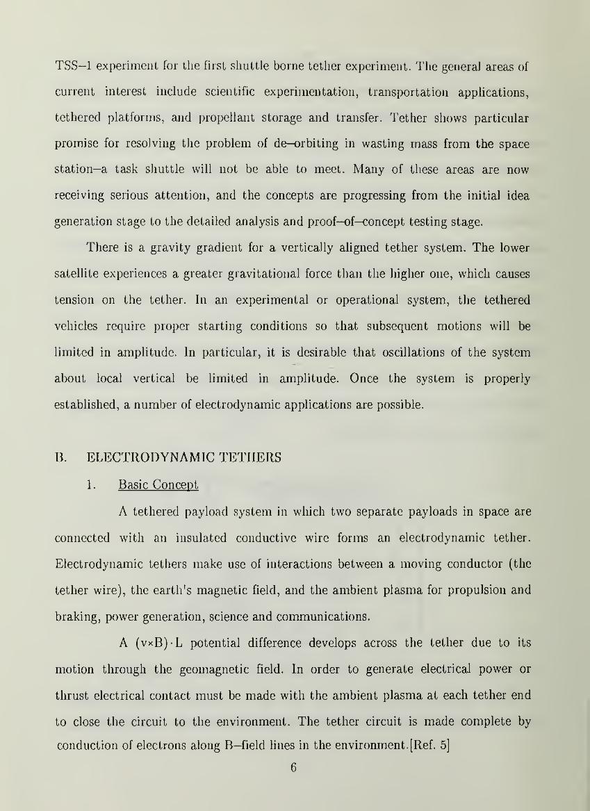
1.1. Figure 1.2 shows the Agena target vehicle configurations. Figure 1.3 shows the
Gemini spacecraft configuration which is composed of adapter and re—entry
module. [Ref. 3]
SPACECRAFT• WIIGHT
.ArflOX 1000 USLAUNCH VEHICLE
• IINCIH . 90 ri
• FUtL
.•UNO OF UDMHANOHTOKAZINE
• OXIDIZER*NIIROCfH IITIOXIOE
• IHIUSI.StACE I
430,000 US-STAGE U
100.000 USSPAdE VEHICLE
• WEICHI AT llTTOrrOVER 340.000 US
SPACECIAET
lAUNCHVEHICIE
It
STAGE I
OXIDIZER
•EUEl
109 II
71 M
- 10 n
mFig. 1.1 Gemini—Titan Space Vehicle Configuration[Ref. 3]
2
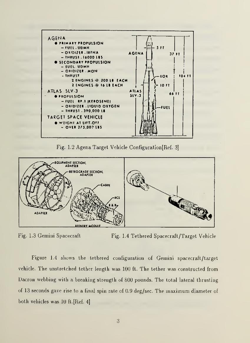
AGE^M• paiMAKY noruiSiON
- run .UDMH-OKIDI2II .IRfNA- IMIUST . 16000 IIS
• SICONDARY PIOPUlStON- rutL UDMH- 0)IIOI7ER MON- TMtUST
2 fNGINlS 'u« 200 II f ACH2 tNCIN(S (^ 16 II lACH
ATUAS SLV 3
• riOPUlSlON- full if \ irnosiNii- OKlDt2EI IIOUIO OXYCtN- tHRUST 390.000 II
TARGET SPACE VEHICLE• WDGHI AT llfT.OM
- OVU 2/3.00r IIS
-̂^ 3 nACtNA 3; FT
104 fT
Fig. 1.2 Agena Target Vehicle Configuration[Ref. 3]
-tOUIfMfNT SfCllON.ADAriER
-lETROCRAOE SECTIOKADArUR
CAIIN
ADAflER
BffNtay MQPuif
Fig. 1.3 Gemini Spacecraft Fig. 1.4 Tethered Spacecraft /Target Vehicle
Figure 1.4 siiows the tethered configuration of Gemini spacecraft /target
vehicle. The unstretched tether length was 100 ft. The tether was constructed from
Dacron webbing with a breaking strength of 800 pounds. The total lateral thrusting
of 13 seconds gave rise to a final spin rate of 0.9 deg/sec. The maximum diameter of
both vehicles was 10 ft.[Ref. 4]
3

On Geiiiiiii XI, a s|)iri—iii) maneuver was successfully conducted with no
evidence of siguilicani, cable—dynamics effects. This confirmed that cable dynamics
were not critical in the rotational behavior (i.e. a spin—stabilized configuration was
siiown to be feasible). The procedure for spinning up the tetheied spacecraft /target
vehicle system consisted of backing the spacecraft away from the target vehicle until
the tether was almost taut, then firing the translational thrusters to provide thrust
on the spacecraft normal to the line between the vehicles. The spin—up moment on
the system was supplied entiiely by the spacecraft translation—control system.
I'^igure 1.5 illustrates the spin—up behavior with and without damping. The
damping is quite effective in eliminating a slack/taut tether oscillation. The bottom
half of Figure 1.5 presents a time history of tension in the tether, and the yaw angle
of the spacecraft relative the target vehicle. It can be seen that the tether tension
was strongly affected by damping.
600
.411(1
£; 200
1., .
,l
]T-
Wilhoul damping
With damping
\
imm^-
3.0 100
lime, sec
150 200
Fig. 1.5 Effect of Damping on the Oscillation of Tetheied System[Ref. 3]

The Gfiiiiiii XII flight experiinoiit was launched on 11 november, 1966.
(Jemini XII sljuiied Uie feasibility of gravity gradient stabilization. The system was
initialized by various translational and attitude thrustering maneuvers by the
spacecraft. This was followed by an active stabilization of the target vehicle using
the target—vehicle attitude control system. The proper starting conditions consisted
of a slightly taut tether, initial alignment along a local vertical, approximately
circular orbit, and a relative velocity of 0.1.38 ft/s (or a 100 ft tethered
spacecraft/vehicle combination. Figure l.G illustrates typical result obtained from
the point mass analysis on the sensitivity of the system motion to initial relative
velocity between the point masses. The main requirement was that the initial
orientation be vertical. The result of this experiment for gravity gradient
stabilization were that with a i)roperly functioning control system operated by the
crew, the initial conditions necessary for the tethered system could be accomplished
with relative ease. The gravity—gradient stabilization orientation was successfully
demonstrated in Gemini XII.
Velocity error • 0.015 (l/sec
Velocity error* .060 (Usee
cr Velocity error •. 150 It/sec
- JOr
fe 20>
8^
™ -20
// // \ \ Pertecl^> ^ \' start
2^-40< 1000 2000 3000 4000
.5000 6000
Time, sec
Fig. l.G Effect of Relative Velocity on Motion of Gravity-Grad[Ref. 3)
This coiicppt has evolved into the set of Tethered Satellite System
experiments. Elertrodynamic applications will be tested with the upward—deployed
TSS— 1 experiment for the first sliuttle borne tether experiment. The general areas of
current interest include scientific experimentation, transportation applications,
tethered platforms, and propellant storage and transfer. Tether shows particular
promise for resolving the problem of de—orbiting in wasting mass from the space
station—a task shuttle will not be able to meet. Many of these areas are now
receiving serious attention, and the concepts are progressing from the initial idea
generation stage to the detailed analysis and proof-of—concept testing stage.
There is a gravity gradient for a vertically aligned tether system. The lower
satellite experiences a greater gravitational force than the higher one, which causes
tension on the tether. In an experimental or operational system, the tethered
vehicles require proper starting conditions so that subsequent motions will be
limited in amplitude. In particular, it is desirable that oscillations of the system
about local vertical be limited in amplitude. Once the system is properly
established, a number of electrodynamic applications are possible.
B. ELECTRODYNAMIC TETHERS
1. Basic Concept
A tethered payload system in which two separate payloads in space are
connected with an insulated conductive wire forms an electrodynamic tether.
Electrodynamic tethers make use of interactions between a moving conductor (the
tether wire), the earth's magnetic field, and the ambient plasma for propulsion and
braking, power generation, science and communications.
A (vxB)-L potential difference develops across the tether due to its
motion through the geomagnetic field. In order to generate electrical power or
thrust electrical contact must be made with the ambient plasma at each tether end
to close the circuit to the environment. The tether circuit is made complete by
conduction of electrons along B—field lines in the environment. [Ref. 5j
6

Figure 1.7 shows the elcctrodynamic tether system with elect rodynamic
drag. Typical ioiiosplieric values, for an orbiting system, result in induced voltage of
several kilovolts lor a 5—lU km system.
©VECTOR SENSEOF B-FIELD
ELECTRONS
ELECTRONS
• E = vx B• VOLTAGE =
JTETHER E*dS
« = iu X B ^^ ~ ""'^ vector along tether)
dS• POWER IN TETHER = RATE OF SYSTEMTOTAL MECHANICAL ENERGY LOSS
• V ~ 8 km/sec• B ~ 0.45 G• E ~ 200 V/km
DRAG VECTORS
Fig. 1.7 Electrodynamic Tether Systern[Ref. 5]
Typical ionospheric densities of lU'^—10^ electrons/cm^, and collecting
areas of a few square meters, suggest that currents of a few amperes can be
collected, to give a net power of kilowatts. Of course, this requires that electrons be
emitted at the same current level at the opposite end of the tether.
2. Electrodynamic Tether Applications
A number of possible applications exist. By applying a voltage between
two payloads connected with a conductive wire, the response of ionospheric plasma

to potential differences between collector and plasma can be studied. By regulating
the current collected (emitted) at the ends, the tether current can be controlled. By
modulating the tether current, low frequency radio waves with long wave length
such as Whistler and Alfven modes, can be excited.
An electrodynamic tether system can be used for electrodynamic
propulsion and braking by using the interaction force between the tether electrical
current- and the ambient magnetic field. In principle it can be applied as an
electrical power generator up to MW level. In this (braking) mode, the kinetic
energy lost by the orbiting system is converted to electrical energy. For ionospheric
science, an electrodynamic tether system can be used to induce controlled,
large—scale perturbations which can be tracked and measured.
3. Tether Experiments
Besides the early Gemini experiments, relatively few experiments have
been conducted. The major planned experiment is TSS—1 which is described next.
a. Tethered Satellite System—1 Experiment
Space shuttle engineering tests of the space tether concept are
planned for the early 1990s using the tether satellite system which is being
developed jointly by Italy and the US. The TSS goal is to test the feasibHty of
deploying, controlling and retrieving a tethered satellite from space shuttle, as well
as to demonstrate the system's usefulness for scientific research. The TSS will
provide a unique, reusable facility for conducting research based from the Space
Shuttle and for conducting proof—of—concept demonstrations of tethered satellite
systems in space.
TSS-1 mission, planned now for late 1992, will be an engineering
verification flight. It will also perform limited electrodynamic science. Figure 1.8
shows the configuration of TSS— 1 satellite system in space. A 20 km—long
8

electrically conductive tetlirr will be deployed above the shuttle (spaceward) to
study the electrodyiiamic properties of the ionosphere as well as conduct plasma
physics experiments.
This mission will test the feasibility of generating electricity with
the insulated conductive tether. This process could be an important source of power
for future spacecraft and space station. As the shuttle moves in earth orbit, the
tether will cut through the planet's magnetic field and interact with the ionospheric
plasma.
TSS-Sa.^flife
r.«*v
•''ih-^ .
Fig. 1.8 TSS-1 Satellite System [Hef. 6]
9

The electrically positive deployed satellite will collect electrons
from the ionosphere. These will be emitted back into space by an electron gun or
plasma source on the shuttle orbiter. This causes a net current to flow upward
through the conductive tether. The intended current is 0.75 A, voltage of up to 3
kV, for a power of a few kW. The tether resistance is about 0.2 fi/m which will
limit the conducted current in the 20 km cable to the above values. [Ref. 6]
b. US—JAPAN Charge Rocket Experiment
Tethered sounding rocket experiments have been underway since
1980 as part of a joint US-JAPAN program (Tethered Payload Experiment; TPE).
Its objective is to obtain technical and scientific data in support of the space shuttle
electrodynamic tethered subsatellite experiments on the space shuttle Tethered
Satellite System—1 mission. The goal of the rocket program has been to perform
active plasma experiments, by ejecting an electron beam from the tethered
mother—daughter payload system. In the third and fourth rocket flights, the
conductive tether wire was successfully deployed more than 400 m. Figure 1.9 shows
the payload configuration of the fourth Tethered Payload Experiment. These latter
payloads have been dubbed charge 1 and charge 2.
The electron gun generated a narrow electron beam of 1 kV, 80 mA
in DC and multi—pulse modes. The floating/Langmuir probe array consisted of 4
cylindrical probes installed on a rod every 25 cm. Two 35 mm cameras with high
sensitivity color film were installed. One was operated synchronized with the beam
firings to observe the beam trajectory. Another was synchronized with flashing of a
strobe light to illuminate the reflective tape attached to the daughter rocket.
Two photometers filtered at 3914 X were used to detect the light
emission from the interaction of the electron beam with the atmosphere and the
charge sheath around the rocket surface. The charge probe was installed to apply a
10
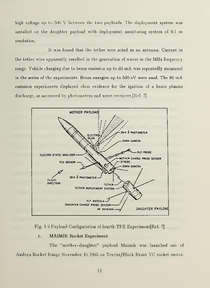
high voltage up \.o 500 V between the two payloads. The deployment system was
installed on the daughter pay load with deployment monitoring system of 0.1 m
resolution.
It was found that the tether wire acted as an antenna. Current in
the tether wire apparently resulted in the generation of waves in the MHz frequency
range. Vehicle charging due to beam emission up to 80 mA was repeatedly measured
In the series of the experiments. Beam energies up to 500 eV were used. The 80 mA
emission experiments displayed clear evidence for the ignition of a beam plasma
discharge, as measured by photometers and wave receivers. [Ref. 7]
MOTHER PAYLOAD;
ELECTRO STATIC ANALYZER
TED SENSOR
XFLIGHTDIRECTION
3SI4 X PHOTOMETER
TETHERTETHER DEPLOYMENT SYSTEM
391* I PHOTOMETER
3SMM CAMERA
PLP PROBE
MOTHER CHARGE PROBE SENSORSTROBE
3SMM CAMERA
VLP ANTENNA
DAUGHTER CHARGE PROBE SENSOR—HF ANTENNA DAUGHTER PAYLOAC
Fig. 1.9 Payload Configuration of fourth TPE Experiment[Ref. 7]
c. MAIMIK Rocket Experiment
The "mother—daughter" payload Maimik was launched out of
Andoya Rocket Range November lO 1985 on Terriei/Black Brant VC rocket motor.
11
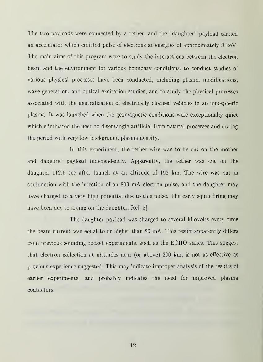
The two payloads were connected by a tether, and the "daughter" payload carried
an accelerator which emitted pulse of electrons at energies of approximately 8 keV.
The main aims of this program were to study the interactions between the electron
beam and the environment for various boundary conditions, to conduct studies of
various physical processes have been conducted, including plasma modifications,
wave generation, and optical excitation studies, and to study the physical processes
associated with the neutralization of electrically charged vehicles in an ionospheric
plasma. It was launched when the geomagnetic conditions were exceptionally quiet
which eliminated the need to disentangle artificial from natural processes and during
the period with very low background plasma density.
In this experiment, the tether wire was to be cut on the mother
and daughter payload independently. Apparently, the tether was cut on the
daughter 112.6 sec after launch at an altitude of 192 km. The wire was cut in
conjunction with the injection of an 800 mA electron pulse, and the daughter may
have charged to a very high potential due to this pulse. The early squib firing may
have been due to arcing on the daughter. [Ref. 8]
The daughter payload was charged to several kilovolts every time
the beam current was equal to or higher than 80 mA. This result apparently differs
from previous sounding rocket experiments, such as the ECHO series. This suggest
that electron collection at altitudes near (or above) 200 km, is not as effective as
previous experience suggested. This may indicate improper analysis of the results of
earlier experiments, and probably , indicates the need for improved plasma
contactors.
12

C. PLASMA CONTACTORS
1. Basic Concept (Requirements and Future Mission)
The ongoing need to establish electrical contact between satellites and
the ambient plasma environment has resulted in studies of devices generically
termed "PLASMA CONTACTORS" which enable low impedance electrical contact
with the ionosphere. This type of device is needed for bidirectional electric current
operation of an electrodynamic tether and stable spacecraft electric reference
potentials.
A plasma contactor might be a large conducting surface, such as an
aluminized mylar balloon. Charged particle emitters such as electron and ion guns
are traditionally thought of in this context. Neutral gas releases can produce
enhanced levels of conductivity. The most effective techniques typically utilize
neutral plasma emission.
Plasma contactor performance can be characterized by plotting the
contactor current versus the contactor potential measured relative to the local space
plasma. Ideal performance is approached if the effective collecting area (for the
appropriate species) is equal to or greater than the associated tether current divided
by the ambient space current density (Ne ^KT/m). The collecting area can be
physical, or simply the enhanced plume area of a plasma source or neutral gas cloud.
Plasma sources have been extensively studied for the purpose of active
charge control. The need for charge control technology has been apparent since the
early 1970's, when it was recognized that satellite charging at geosyncronous orbit
reached kilovolt levels, and that such charging might be related to satellite failures.
In this regime, current levels of microamps are typically found. [Ref. 9]
The European Space Agency CLUSTER spacecraft scheduled to be
launched in the mid—1990's will have conducting surfaces so that the behavior of
13
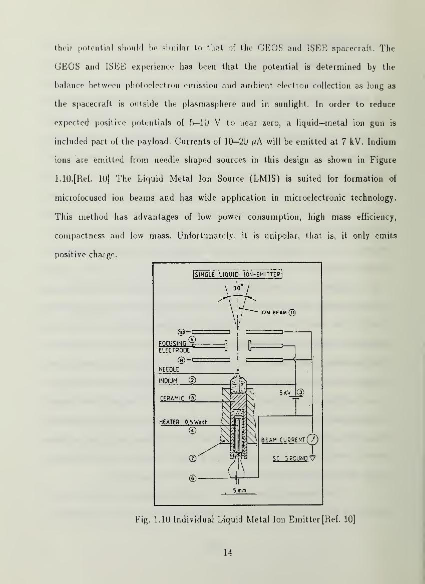
tlif'ii [intpptial slionUl ix- sidiilar to t.lint of tlir TjEOS and ISEE spacecrait. The
GEOS and ISEE experience has been that the potential is determined by the
balance betweeji iiholdrloction eiriission and aiiibiont electron collection as long as
the spacecraft is outside the plasniasphere and in sunlight. In order to reduce
expected positive potentials of r>—1(J V to near zero, a liquid—metal ion gun is
included part of the payload. Currents of lU—2U /tA will be emitted at 7 kV. Indium
ions are emitted from needle shaped sources in this design as shown in Figure
1.10.[Ref. lU] The Liquid Metal Ion Source (LMIS) is suited for formation of
microfocused ion beams and has wide application in microelectronic technology.
This method has advantages of low power consumption, high mass efficiency,
compactness and low mass. Unfortunately, it is unipolar, that is, it only emits
positive charge.
SINGLE LIQUID ION-EMITTEI?|
\'»•
/
@-c:(9)
FOCUSING Y-
7""""— ION beam(Ti)
i'3 C
ELECTRODE
(D-cNEEDLE
^ I t3
;c
A
3 <;
INDIUM @
CERAMIC (D
HEATER O.SWatr
/^ ^.
5KV (D
BEAM CUgRENT( /;
SC j?CUNO'
5 mm
Fig. I.IU Individual Liquid Metal Ion Emitter [Ref. 10]
14
The scientific objectives of many sounding rocket active experiments
have been to study the propagation of plasma beams through the ionospheric plasma
in the presence of the earth's magnetic field. Recent interest has been stimulated by
active experiments on the space shuttle orbiter, such as the former SPACELAB
payload, SEPAC, a large electron gun experiment (1 A, 10 kV), which will be reflown
as part of the ATLAS payload.
The 1983 SEPAC experiments included large positive potentials on the
shuttle orbiter. To prevent such charging, net positive (e.g. ion) currents of ampere
or more are desired. This would allow the fundamental mission objective of
transmitting an electron beam through the ionosphere to the top of the atmosphere
to be achieved. The joint Italian—American Tethered Satellite System (TSS—1) is
scheduled for a late 1992 flight on the shuttle orbiter. In the case of TSS—1, plasma
sources are needed to collect and emit the estimated 1 A current which will flow
along the tether wire to the orbiter.
It is anticipated that charge control technology will be needed for the
space station, particularly if active plasma experiments are to be conducted from
that platform. Orbital systems which emit large fluxes of charged particles presently
being considered for defense purposes will also require this technology.
2. Plasma Contactor Flight Historv
a. Balloons
The free space capacitance of a typical rocket payload is so small
that ejection of even a 1 mA beam will charge the vehicle to more than 10 kV in less
than 1 msec. Consequently, if the electron beam current is not neutralized by
ejection of an equal positive ion current, sustained ejection of electrons will require
the collection of an electron return current through the ionosphere plasma.
15

The assurance of an adequate collection of return current can be
addiessed by deploy uig a large collecting surface. For this purpose, a large
inflation—deployed electron collection screen was developed and fabricated for the
first US rocket—borne electron accelerator experiment. The experiment carried
electron guns capable of up to 49(J inA at 9.5 keV. This artificial aurora experiment
was launched on an Aeiobee 350 from Wallops Island in January, 1969. The rocket
payload included an a.luininized mylar disk, 26 m in diameter, with aji inflatable
hub and rim and four inflatable spokes. The collector is illustrated in Figure 1.11.
The deployment was apparently incomplete, due to a malfunction in a pressure
regulator. Nevertheless, the technique was at least partially successful. [Ref. 11]
|7" DIfl HLLIUMiMFLATEO RIBS
(4,^0 RIMS
85 ff DIA. 1/4 mil MYLARCOLL ECTOR
(CONDUCTIVE COATEO AREA ?SIDES"^-^Bn '^niiflRF FFET EACH 1
Fig. 1.11 Collector Screen in the Deployed Configuration[Ref. 11]
ECHO 1 was launched on 13 August, 1970. This experiment
apparently showed that the conducting rocket body could collect a sufficient return
current for beam neutralization without a special collector disc or other device3.[Ref.
12]
16
b. Electron Gun
Electron guns are a primary form of a plasma contactor. Electron
guns have been used in space at current levels from microamperes to amperes.
Examples of flight experiments are as follows:
The first was the above mentioned Artificial aurora experiment.
This experiment was a first feasibility test in the development of a system for the
study of magnetospheric field configurations through the controlled injection of
monoenergetic electron beams on to magnetic—field lines. Energies up to 9.5 keV
and beam currents up to 490 mA were used. In this experiment, the vehicle
neutralization was accomplished by collecting an ionospheric current using
aluminized mylar foil deployed perpendicular to the magnetic field. [Ref 11]
In the ECHO series of sounding rocket experiments, electron guns
with energies of 40 kV and current levels of 100 mA and above have been used to
study magnetospheric plasma phenomena. Beginning with ECHO I, it was found
that sufficient beam electrons escaped to the top of the atmosphere to generate an
artificial aurora. In this sense, the 'contactor' was adequate to couple lO's—lOO's mA
to the environment. [Ref 13]
Space Experiments with Particle Accelerator (SEPAC) was
designed to perform an active experiment in space by ejecting a high power electron
beam up to 5 kV, 300 mA (e.g. kilowatt power) from shuttle orbit. It apparently
failed in this function, due to shuttle charging, and the occurrence of a beam plasma
discharge, which disrupted the beam. [Ref 14]
A second (French) payload carried on the same spacelab mission
was dubbed PICPAB. This lower power electron gun (10 mA, 8 kV) was designed to
study wave generation. Diagnostics were inconclusive, but appear to indicate the
beam resulted in low potentials, and hence the beam escaped. [Ref. 15]
17

A series of the US/JAPAN tethered rocket experiments used
electron guns of 1 kV, 80 mA in DC and multi—pulse modes as described previously.
The CHARGE rockets have been at least partially successful in propagating beams
away from the vehicles.
The MAIMIK experiment used an electron gun with 1—3.2 kV and
20-800 mA. The MAIMIK experiments, were also successful. These experiments
resulted in some observations indicating that the vehicle charged to near or above
beam energy, however, limiting the emitted current. In fact, it appears that a
virtual cathode formed, and only 1—10 % of the beam escaped. The escaping
electrons were accelerated to 110—120 % of the beam energy.
The ATS—5 filament neutralizer was used as an electron emitter at
microampere current levels at geosynchronous orbit. ATS—5 electron emitting
operations succeeded in reducing the magnitude of the negative eclipse charging
potentials on the satellite. However, the spacecraft was rarely discharged
completely. This was the result of differential charging on the satellite surface
limiting the emitted current.
This means that on high altitude satellites with substantial
portions of the satellite covered with insulators, electron emitters are generally
ineffective as plasma contactors. SCATHA experiments used an electron gun at
levels ranging from 1 ^A to 13 mA, and from 50 V to 3 kV. SCATHA experiments
showed that even with high energy beams differential charging prevented beam
emission. [Ref. 16)
c. Neutral Gas Releases
The injection of a plasma or a neutral gas is one way to neutralize
the spacecraft. The mechanisms which are important are those which result in
substantial ionization of the neutral gas cloud. This may be due to the beam itself,
18

the return (collected) electron flux, or perhaps even secondary electron emission
from the vehicle surface. Under some conditions, it is believed that as the ionization
process proceeds, electrostatic waves are set up, which increase the ionization rate,
instigating a Beam—Plasma Discharge (BPD).[Ref. 17]
Neutral gas releases were used on ECHO I. No direct evidence of
effective vehicle neutralization was obtained. Indeed, the ECHO I results have been
traditionally interpreted with the thought that the rocket body provided adequate
return current collection. ECHO IV experiment considered again the effect of a
neutral gas release. The 40 kV, 80 mA beam was fired through an N2 plume which
had densities were obtained by means of a photometer calibrated at 3914 X. The
return current was enhanced by the neutral N2.[Ref. 18]
Possible occurrences of BPD during sounding rocket experiments
are described by J. R. Winckler. The BPD conditions are that:
yl- 5
Ic = C go-7pL (1)
where V is the accelerating voltage, B the magnetic field, P the pressure and L the
scale length of the experiment. Since beam perveance is generally of the form laV'"^,
it is clear that beam perveance determines the occurrence. Winckler concludes that
BPD has been observed. [Ref. 19]
This technique was also used in the SEPAC experiments with
beam energy of 2.9 keV and current of 200 mA. The neutral gas plume (NGP)
emitted 10^3 molecules of nitrogen (N2) in a 100 ms pulse. The gas release resulted
in a neutral gas pressure increase in the shuttle bay, from 10"^ Torr to 2 — 3x10⁻⁶
Torr. This technique was apparently successful, but appears to have involved
substantial interactions with the ambient neutrals and plasma. One curious aspect
19

of these experiments was that the 8 keV, 10 mA PICPAB beam did not result in
substantial ionization of the emitted neutrals. This may be related to the relatively
low shuttle potentials induced by PICPAB (~ +10).[Ref. 20] There is substantial
disagreement in the literature over occurrence of BPD in the SEPAC
experiments. [Ref. 21]
d. Ion Beams
A non—neutral ion beam is a form of plasma contactor. The ARCS
series experiments used Argon ion beams to study the electrodynamics in the
ionosphere. A 100 mA, 25 eV Ar* ion beam was used on experiments beginning with
a sounding rocket ARCS—1, launched on 27 January, 1980. Electrons were observed
to be accelerated toward the beam emitting payload during ion beam operations.
This effect was ascribed to the creation of an electric field parallel to the
geomagnetic field. There also appear to have been substantial electron heating,
apparently due to wave turbulence associated with beam operations. [Ref. 22]
ARCS—3 was launched on 10 February, 1985. This experiment
showed that the injection of particles parallel or perpendicular to the geomagnetic
field consistently resulted in the appearance of a population of ions at low energy (~
15 eV) and at 90o pitch angle. These ions apparently are scattered out of the beam.
These experiments indicate that the sounding rockets are able to draw neutralizing
currents to the beam and rocket via complex processes which accelerate and
thermalize the ambient plasma. It appears that the beams do escape. [Ref. 23]
Another form of ion beam is ACED (Accelerator with Closed
Electron Drift). ACED was initiated in the United States but appears to have been
abandoned in the mid-60's. Subsequently, it was taken up in the USSR. An ACED
thruster was used to adjust the near synchronous orbit of one of the "Meteor"
satellites. The ACED ion beam source delivered 4 A of Xenon ions at 200 eV.[Ref.
24]
20
It was supplied by the Soviet participants for the West—German
"Porcupine" program of rocket experiments in the auroral ionosphere. Porcupine
rockets F3 and F4 were launched in March, 1979 from the European Space Research
Range. The Xenon ion beam was injected perpendicular to the ambient magnetic
field into the collisionless ionospheric plasma at altitudes ranging from 190 to 450
km. These experiments showed that the beam propagated nearly undistorted across
the plasma. The beam was not current neutralized. [Ref. 25]
e. Ion Engine
An ion engine is a device which combines an ion beam with a
charge and current balancing electron source. There is generally little net
current.The first major ion engine flight experiment was .\TS—4 launched on .August
10, 1968. ATS—4 was intended to be a geosynchronous satellite but the booster
failed to achieve a second burn. ATS-4 remained attached to its Centaur Stage
booster, and remained in a low parking orbit. In spite of this failure, a number of
successful ion engine tests were run. Two ion thruster systems were on board, and a
spacecraft potential monitor that employed one of the gravity gradient booms as a
Langmuir probe. [Ref. 26]
The boom was deployed prior to the last of five ion engine test
periods. The large ram ion currents available from the relatively dense ambient
plasma (altitude 218 to 760 km, density 10 lo/m^, ambient pressure 10"9-10"6 Torr,
current 330 /;A, spacecraft potential —132 V) precluded the achievement of
appreciable neutralizer emission current except for a few brief periods. With the
exception of the emission limited behavior of the neutralizer during test 5, both ion
engines performed normally in all respects. Particularly gratifying were the
complete absence of detectable electromagnetic interference, and the lack of arcing.
21

UJ 3,1- ^3 5S S ^ 2 31— O tZ t'l <I
Q^ h— _
o: I—
MENTED
ODES a
VECTO •<UJm
zUJ
£to
*s ac , .»—
UJ fr H^ _J•/'o^i^S Si
:3>
PLITEL
ELElO oUJ oCJ oKn cj CM
cr cr uUJ UJ .
a:
'
UJ0. en«« —
'
> »-•
'
=E2 UJCO UJUJ u.«J
Jz ^
oa.
tn»—_io>ooo
2 -4_ 3ECO OL
o 3= CO» UJ
o :35 oin=> COo oac UJO UJa. u.
O>.^'^ I"O UJ UJ
I U. oc
UJ =J
UJ UJO (—to
Fig. 1.1'J Configuration of ATS-v^) Ion TluustcrfHfl. !(.]
' y
)
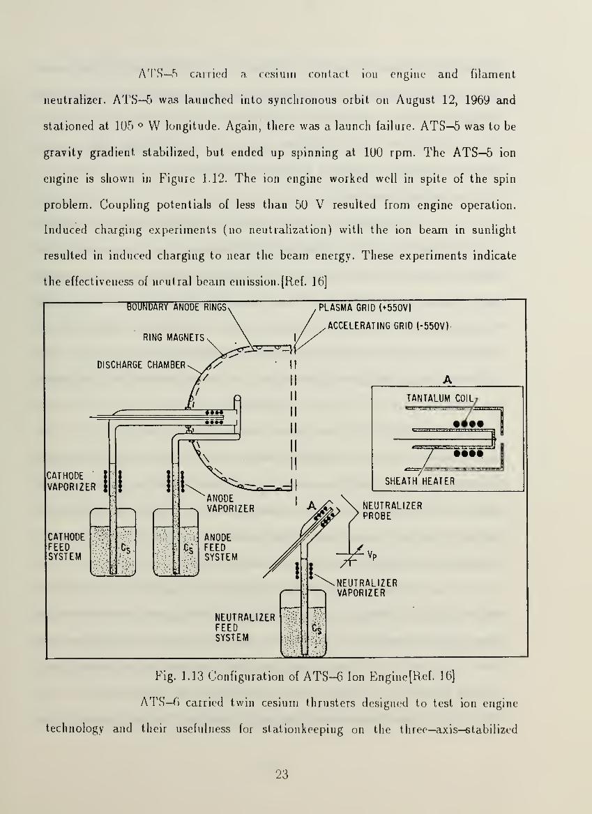
ATS—^^ carried a cesium conlact, ion engine and filament
neutralizer. ATS-v) was launched into synchronous orbit on August 12, 1969 and
stationed at 10!") ^ W longitude. Again, there was a launch failure. ATS^ was to be
gravity gradient stabilized, but ended up spinning at lUO rpm. The ATS-^ ion
engine is shown in Figure 1.12. The ion engine worked well in spite of the spin
problem. Coupling potentials of less than 5U V resulted from engine operation.
Induced charging experiments (no neutralization) with the ion beajii in sunlight
resulted in induced charging to near the beam energy. These experiments indicate
the effectiveness of neutral beam emission. [Ref. 16]
BOUNDARY ANODE RINGS
RING MAGNETS
DISCHARGE CHAMBER
CATHODEVAPORIZER
CATHODEFEEDSYSTEM
PLASMA GRID USSOV)
ACCELERATING GRID 1-550V)
^S ^S
•ANODEVAPORIZER
ANODEFEEDSYSTEM
TANTALUM COIL*'.r .'."a: , ,i-.ir. jLi.J.'L'.'.ii. '
••••I. -ll Ml Jll' 1 HI. I
:i:^ "^".'..*J
••••=mv.', u; '. ". itti f.L".ritinTTri
SHEATH HEATER
NEUTRALIZERPROBE
NEUTRALIZERFEEDSYSTEM
Vp
NEUTRALIZERVAPORIZER
'^--^
Fig. 1.13 Configuration of ATS-6 Ion Engine[Hef. 16]
ATS-^i carried twin cesium thrusters designed to test ion engine
technology and their usefulness for stationkeeping on the three-^axis-stabilized
23
satellite, It was launched in 1974. Figure 1.13 shows the ATS-6 ion engine
schematic with neutralizer. ATS-6 engine operations were successful, and had the
beneficial side effects of discharging the mainframe and all differentially charged
surfaces. The plasma bridge neutralizer alone could also discharge large negative
potentials in sunlight or eclipse. A 92 hour operation of the ion engine at 160 mA, 3
kV was successfully conducted.
A geophysical rocket was used to launch an automatic ionosphere
space—flight laboratory (SFL). Experiments with this rocket were conducted by the
USSR in November, 1969 and August, 1970. These experiments made use of an ion
engine using surface ionization of cesium on tungsten to study the operation of the
various systems of this engine. The maximum value of the ion beam current was 100
mA (240 sec) and the effective accelerating voltage was about 2400 V. The
magnitude of the potential was about —1700 V and the thickness of the space charge
layer surrounding the SFL was about 7 m.[Ref. 27]
SERT—II (Space Electric Rocket Test II), carrying dual 15 cm
diameter mercury electron bombardment ion thrusters, was launched on February 3,
1970 into a polar, sun—synchronous orbit at 1000 km altitude. The primary purpose
of SERT—II was a long duration (6—month) test of a mercury ion thruster. A
secondary objective was investigation of the interaction between the ion thruster,
the spacecraft, and the ambient space environment. [Ref 28]
Emissive probes flown on the SERT—II spacecraft in conjunction
with the prime ion thruster experiment allowed an investigation of the interaction
between the spacecraft, the ion thruster, and the ambient space plasma. One
thruster operated for 5—months and the other operated for 3—months. Both
thrusters failed due to sudden shorts between the high voltage grids. It was
determined that the cause was sputtering of grid surfaces. The specific impulse was
24

I
about 4200 sec, and thrust was a 28 mN for a thruster input power of 850 W. The
main objectives were largely reached. The engines were operated at 253 mA, 3 kV
for 600 hours. They demonstrated thrust, and an absence of harmful interactions
with the vehicle. [Ref. 29]
The mean SERT—II spacecraft equilibrium potential with the
engine off was —6 to —8 V. This relatively high negative potential was due to the
presence of exposed solar array interconnections at high positive potentials (36
Volts). The space probe measurements indicated that photoemission had no
detectable effect on spacecraft potentials. It was possible to control the potential
difference between the spacecraft and the space plasma, using the neutralizer bias.
This effect could be used to minimize electrostatic influence on the space plasma of
an ion thruster bearing spacecraft. The ion beam neutralizer potential difference was
constant for all neutralizer biases (with respect to the spacecraft ground) with a
constant neutralizer emission current. [Ref. 30]
In 1973, new goals were added for the still functional SERT—II
spacecraft which included, i) demonstration of thruster restability after long space
storage, ii) study of factors limiting thruster restarting, iii) demonstration of the
space lifetime of thruster system components, such as propellant feed systems,
closed loop control systems, insulator shields, and power processor units, iv)
measurement of main solar array degradation after years of space exposure, and , v)
verification of the compatibility of the spacecraft system with sustained thruster
efflux. Minor components of the spacecraft had failed, but this did have not interfere
with the functional status of the spacecraft. The short between the engine grids
removed itself, apparently due to mechanical stress. [Ref. 31]
In 1974, the spacecraft was placed into a spin-stabilized mode in
order to be ready for the next period of complete solar—array illumination. In 1979,
25

additional goals wcic addfd : 1) dcnionstratioii of sl.rady stale opeiatioii of an ion
tlirustci systcin !) years alter launch, 2) nicasnreineiit and comparison the
performance of this agfl tjiinstei vvitli tjiat of a new thrnstei, and 3) long term
operation of the ion thiuster system to determine its life limiting factor. Again, the
engines vvorkc^l well after 9 years in orbit. Dining the first cpiailer of 1979, thnister
2 was operated for neaily t)OU hours at 85 mA beam current. The performance of the
thrustei was found to be unchanged in the 9 years. The spacecraft remained
functional and had only experienced minor failures of a battery in the telemetry
system and the loss one of one tape recorder. [Ref. 32]
01 particular interest are the plasma contac:tor aspects of the
SERT—II expeiiments, peirticularly the beam neutralization. The SERT—II
neutralizers were hollow cathode, plasma bridge neutralizers. Figure J.H shows a
-25 MN| = 10''/cm^-10^ m I i
. -r "N'MO^/cm^ (AMBIENTL ^ -^' TcT'o'^rc
^ ~- '*''^^'^'"
" \ '
I V ^-- EXCESS ELECTRONS,
CURREMT NEUTRALIZATION
FROMT/S-1 (UPT0 85mA)
PRIMARYAMBIENT -^ \ BEAM
ELECTRON-"^ \ N|-lo8/cm^
FLUX; ~<1 mA/m \lONS~85mA
OF BEAM LENGTH
/
j^r- EXCESS ELECTRONS
/' FOR SPACE
NEUTRALIZATION
-1 m
s. I
r NEUTRALIZER ^\
/ Ni~10^°/cm3
CHARGE I \ ^i~
EXCHANGEt- \6x10''N; ~ r' \ k
IONS~9mA'v
A IONS- 2 mA
^MAIN DISCHARGE*.^-
NEUTRALIZERNj~10l0
IONS- 2 mA
^ Nj~10l^
IONS- 40 mA
) IS CHAR
T/S-1
SPACECRAFT
Fig. 1.14 Spacecraft Plasma Current Diagram of SERT-II[Ref. 33]
2fj
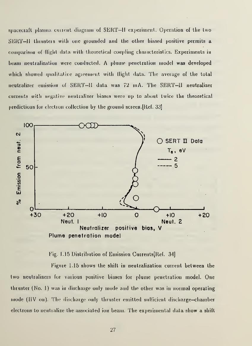
spacecraft plnsiiia cuiiciii (I'uigraiii of SEllT—II experiiiiciil. Operation of the two
SEHT—11 tliiuslcis vvil.li one grounded and the other biased positive permits a
conii)ari3()u of flight data willi thctjretical coupling chai<w.tcristics. Experiments in
beam neutralization wcie conducted. A plume penetration model was developed
which showed (pialilal ive agiceiiHMit with flight data. Tiie average of the total
neutralizer emissiu!i of .SEilT—II data was 72 inA. The SEllT—11 neutralize!
currents with iirgallvf neulrallzei biases were up to about twice the theoretical
|)redictions for election collection by the ground screen. [Kef. 33]
100
CM
3C
Eo^ 50
s
•MM
EUJ
OCCD
O SERT n Data
e • eV
5
+30 +20 +10 +10
Neut. I Neut. 2Neutralizer positive bias, V
Plume penetration model
+ 20
Fig. 1.15 Distribution of Emission Currents[llef. 34]
Figuie 1.15 shows the shilt in neutralization current between the
two neutralizeis for vaiious positive biases for plume penetration model. One
thruster (No. 1) was in discharge only mode and the other was in normal operating
mode (IIV on). The discharge only thruster emitted sufficient discharge—chamber
electrons to neiitializc the associated ion beam. The experimental data show a shilt
27
Iroiii iieulializci 2 niiiissioii at a iicutralizer 1 bias of 12—IG V to all neutializer
leiiiissioii at a iiciil.iali7.(:r 2 pu.silive bias of (j V.[Ref. 34]
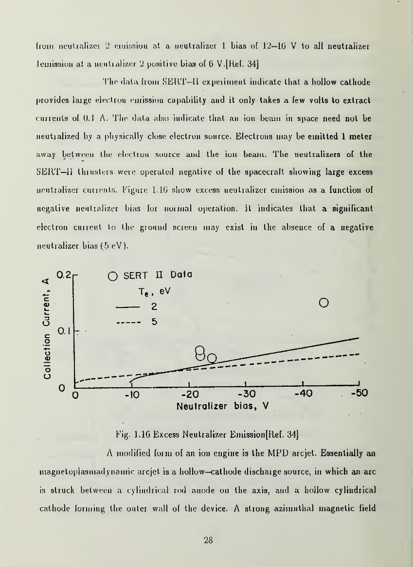
TJio (lata tiom SERT—11 cxpeiiiiienl iiidirate lliat a hollow cathode
provides laige eledruii ciniasion captibilily and it only takes a few volts to extract
cuiieiils of 0.1 A. Tlir data nlso iiidicalc thai an ion beam in space need not be
neutialized by a pliysicaily close electron source. Electrons may be emitted 1 meter
away botwrrn Uie clcclroii source and the ion beam. The neutrallzets of the
SEllT—11 lhrusl(;r3 were operated negative of the spacecraft showing large excess
nonlralizer curroiil,^. Figuie l.lfj siiow excess nculralizer emission as a function of
negative nenlralizer bias for noimal operation. It indicates that a significant
electron current to tiic ground screen may exist in the absence of a negative
neulralizer bias (5 eV).
0.2r
c01k-
3uco
o0)
"oo
0.1
O SERT n Data
Te, eV
2
5
-10 -20 -30
Neutralizer bias, V
o
-50
Fig. 1.16 Excess Neutralizer Emissionfllef. 34]
A modified form of an ion engine is the MPD arcjel. Essentially an
magnetoplasmadynamic arcjet is a hollow—cathode dischaigc source, in which an arc
is struck between a cylindrical rod anode on the axis, and a hollow cylindrical
cathode forming the outer wall of the device. A strong azimuthal magnetic field
28
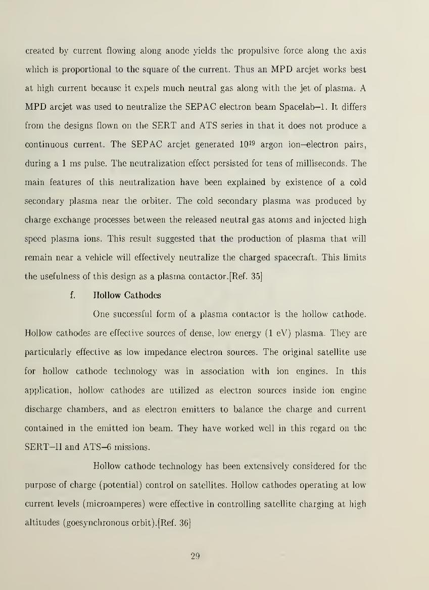
created by current flowing along anode yields the propulsive force along the axis
which is proportional to the square of the current. Thus an MPD arcjet works best
at high current because it expels much neutral gas along with the jet of plasma. A
MPD arcjet was used to neutralize the SEPAC electron beam Spacelab-1. It differs
from the designs flown on the SERT and ATS series in that it does not produce a
continuous current. The SEPAC arcjet generated lO^^ argon ion-electron pairs,
during a 1 ms pulse. The neutralization effect persisted for tens of milliseconds. The
main features of this neutralization have been explained by existence of a cold
secondary plasma near the orbiter. The cold secondary plasma was produced by
charge exchange processes between the released neutral gas atoms and injected high
speed plasma ions. This result suggested that the production of plasma that will
remain near a vehicle will effectively neutralize the charged spacecraft. This limits
the usefulness of this design as a plasma contactor. [Ref. 35]
f. Hollow Cathodes
One successful form of a plasma contactor is the hollow cathode.
Hollow cathodes are effective sources of dense, low energy (1 eV) plasma. They are
particularly effective as low impedance electron sources. The original satellite use
for hollow cathode technology was in association with ion engines. In this
application, hollow cathodes are utilized as electron sources inside ion engine
discharge chambers, and as electron emitters to balance the charge and current
contained in the emitted ion beam. They have worked well in this regard on the
SERT-II and ATS-6 missions.
Hollow cathode technology has been extensively considered for the
purpose of charge (potential) control on satellites. Hollow cathodes operating at low-
current levels (microamperes) were effective in controlling satellite charging at high
altitudes (goesynchronous orbit). [Ref. 36]
29
Hollow cathodes have been operated as high current sources (100
mA) in association with the SERT—II ion engine experiments as described in the
previous section.
D. PROPOSED EXPERIMENT
We propose to test hollow cathode technology for application as plasma
contactors, using a tethered system, deployed from a sounding rocket.
In this study, deployment systems of different tethered rocket experiments will
be investigated in order to choose a proper deployment system for the hollow
cathode rocket experiment. Modeling of tethered deployment system will be studied
using the numerical integration method. This modeling work will be compared with
our experimental configurations.
30

II. TETHER DEPLOYMENT
A. BASIC DYNAMICS
The dominant tether dynamic behavior, when tip masses are present, is the
rigid—body in—plane libration. If we assume that the tether is massless, then the
system behaves as a dumbbell subject to only trajectory dynamic effects. The
geometry is shown in Figure 2.1. The tether length 1, is allowed to vary as a
controlled function of time, since the deploying rate will be used as a control input
for precise positioning of the tether tip.
Fig. 2.1 Dumbbell Tether Model
The nature of the tether dynamics suggests two different control inputs. The
first is tether reeling acceleration. This can be used to achieve the desired tether
length and reeling rate. The second technique is to use small thrusters on the tether
tip vehicle. These can be cycled on or off to control the tether pitch angle and
31

pitching rate. Only one dimensional separation dynamics of the tether are
considered here, thus allowing reeling motions along the tether length.
B. HOCAT DEPLOYMENT OBJECTIVES
The configuration we are proposing for HOCAT is illustrated in Figure 2.2.
The subsatellite would be deployed gradually to a maximum extent of about 100
meters. This separation distance has been selected for practicality (e.g. a reasonable
distance in the available time), and as a logical step up from the 1—10 m vacuum
chambers currently in use for testing hollow cathodes.
The intention for HOCAT is to utilize the same tether used previously on the
ISEE—1 satellite. This material consists of a Kevlar strand with 8 inner conductors,
shielded with a conducting outer sheath. It has a tensile strength of about 600
Newton. Several other versions of higher strength are available with only a small
weight penalty. The conductors have a resistance of about one ohm per meter so
that we would power the sub—payload with separate, local batteries.
The tether link can be used to carry commands to the daughter payload, and
return command verification and instrument parameters to the main payload, where
the telemetry systems would reside. The tether will provide us the capability to
electrically isolate, connect or drive the potential of the sub—satellite and the tether
independently, in order to study the operational characteristics of an electrodynamic
tether, particularly the plasma contactor aspects.
Two main options were initially considered. These were a spinning, or bolo
configuration versus an inertial system. In order to be capable of measuring the
conductor's effects at a variety of aspect angles to the magnetic field, the entire
configuration should be rotating about a common center of mass. The tensile
strength largely determines the spin rate of the satellite system.
32

PARTICLE PLASMA /\.DETECTORS / %/ 2nd DC-E
n^ / / PROBEDC E-N/PROBE ^^xn/ / .
HOLLOW /nr^/^^^^-^CATHODE # 1 / 1//lL ^3
HOLLOW /O /CATHODE #2 /I/ CURRENT LOOP
\vV 3^^ STAGE MOTOR
Fig. 2.2 Hollow Cathode Configuration
33

An initial spin rate of 'M) rpin, will result, in a final spin of near zero at
maxiiiiuin doplovineiit (For an initial separation of 1 meter, and end masses of lOU
kg, a centripetal force of about 50(J Newton results, and hence a reasonable tension).
This configuration does put a substantial strain on the deployer, however, and
complicates that design. For simplicity, therefore, an inertial system is focused on in
the remaining work.
In order in minimize meclianical design costs, we wish to maJce use of
experience obtained by other experiments. The major pievious experiments, are the
•Japanese CHAR/JE, and Norwegian MAIMIK experiments. Two future experiments
are Canadian OEDIPUS and TSS-l
1. US— lAPAN .Toint Experiment Deployment System
The I ether wire was deployed at mother—daughter separation by a
multiple spring system. Separation speed was set at (J.5, 1.0, 1.5 and 1.05 m/s in the
first, second, third and fourth experiment respectively. In the first two experiments,
the deployment s[)eed gradually decreased with time, and finally stopped abruptly
at 38 m and (>5 m respectively, due to a frictional force in the tether deployment
systein. However, in (he last two experiments, an improved deployment system,
called a Reaction (Jontrol System (KCS) was used on the daughter rocket. The RCS
operated witli gas jets every K) sec to compensate for the friction.
This system is characterized by a non—constant deployment speed.
Mechanically, the deployer design is similar to a spinning reel (e.g. a fishing reel).
McCoy has adopted a similar strategy for his Plasma Motor Generator test. To
model the deployment system, without a RCS, from the above data, the equation of
motion for the sepaiation of the tethered payload system can be solved by
expanding the separation distance in a Taylor series where the separation distance is
expressed as a function F(t):
34
F(t4-At) = F(t) + F'(x)At + F"(t)^ + • -Fnlt)^ (2)
The first, neglected term provides an estimate of the local discretization
error. The equation of motion of the separating system can also be expressed:
x + -^i = (3)m ^ ^
where x is the separation distance, m is mass of the daughter payload, and c is a
combination of the different frictional constants.
Equation (3) was first solved analytically to obtain the constant c/m, by
using tlie known values of the initial velocity, and time from the first two
experiments (e.g. —4-t—- = — ). In anticipation of less linear systems, numerical
integration was used to model the separation. The coefficient c/m was determined
to be (J.OOOli, which gives a separation distance of 35.4 m and 71 m for initial
separation velocities 0.5 m/s, and 1 m/s respectively. In the second experiment, the
maximum separation was 65 m, which indicates that the acceleration is not linear
with velocity. To model this nonlinearity in the drag, a quadratic or cubic term was
included, making the differential equation;
X = C|X + C2 x^ (5)
Trial and error solutions yielded C| 0.0001817 and C2 0.0000599 for the
quadratic equation, giving rise to 34.7 m and fi5.4 m for 0.5 m/s, and 1 m/s . For
the cubic equation, the analytical values of ci and C2 are 0.000196, 0.0000499 giving
the separation distances of 34.93 m and 65.1 m for 0.5 m/s and 1 m/s respectively.
This agree very well with the practical data of US—JAPAN experiment
35
«• •• 8« !•• IM
Time (sec )
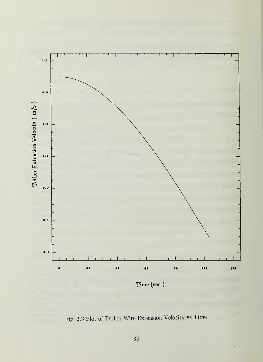
Fig. 2.3 Plot of Tether Wire Extension Velocity vs Time
36

1—I—
I
1—
I
1—I—
I
1—
I
1—I—
I
\—I—
I
1—
I
1—
I
1 r
et —
ei
B
u
.9Qao"(3 4»
Eh
8*
J I I I I I I I I 1 I I I I I I I I I I I I I
8« 4t et •• !•• 18t
Time ( sec )
Fig. 2.4 Plot of Tether Separation Distance vs Time
37

without ROS. FigiiK^s J. 3 and 'J. 4 show how tlip volofity <\ii(l separation distaiire
change with ifspcct to timt- lor a system witli initial velocity 1 in/s, and drag
similar to the t^S— lAl'AN experiment. In the third aiid louith experiment, the
tether deployed to a length o( 418 m during 283 second and 426 m during 29U second
resjiectively. Figure J.'S shows the wire deployment for the velocity of fourth
experiment with the Reaction Control System on board.
Fig. 2.5 Deployment Velocity of fourth US-JAPAN Experiment[ref. 7]
2. MAIMIK Rocket Experiment Deployment System
The MAIMIK rocket payloads were separated at an altitude of 86.5 km
some 62 second eifter launch with relative speed of 0.8 m/s. During the separation,
the payloads axes were tilted at an angle of 23 ± 2 degrees relative to the local
geomagnetic field vector. Hence, the relative cross—field daughter velocity was 0.3
m/s.
38
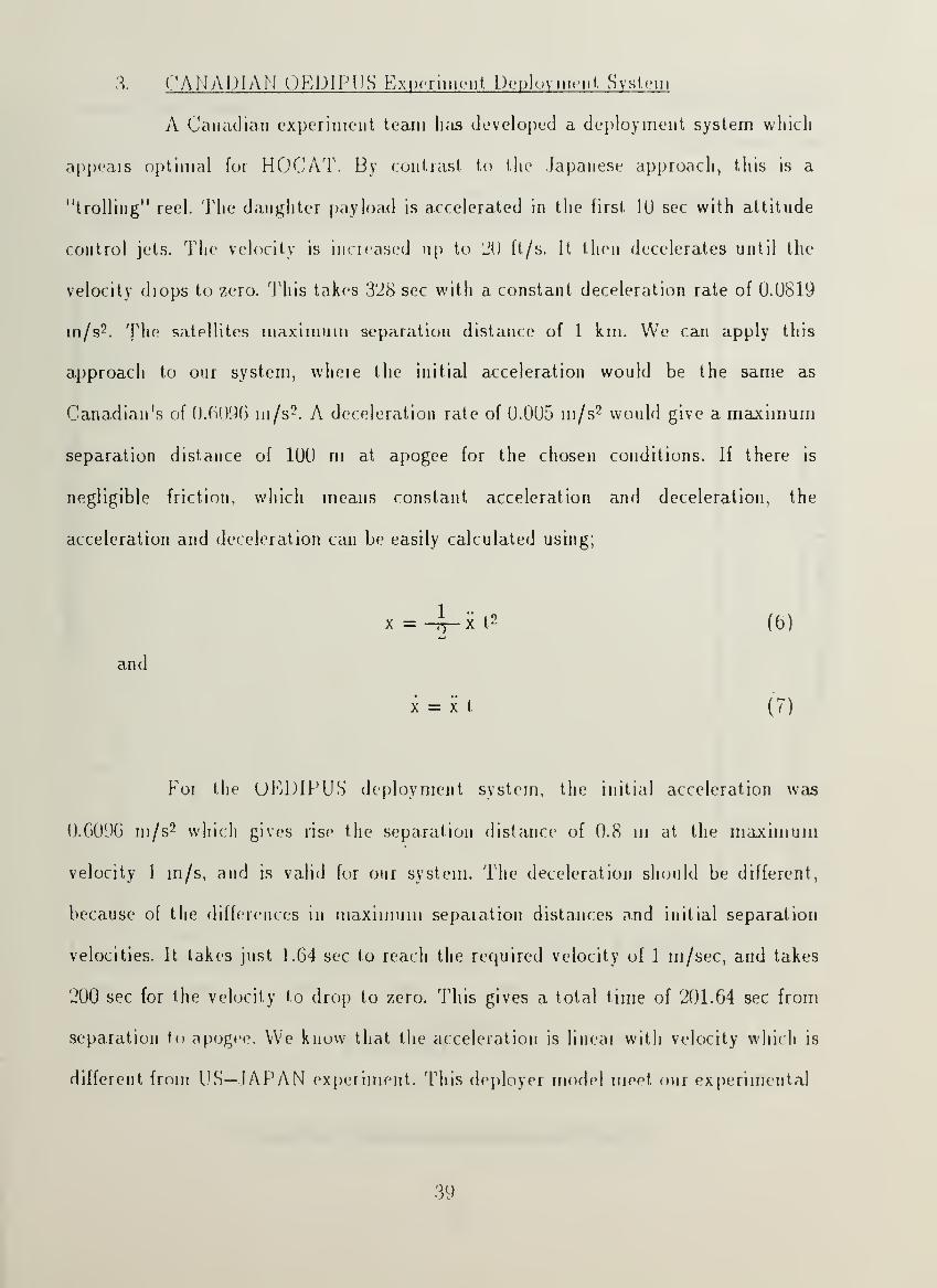
3. CANADIAN OEDIPUS Ex[KTiiiicni DeployiiK-nl. Sysleni
A Canadian experiment team has developed a deployment system which
appears optimal for HOCAT. By contrast to tjie Japanese approach, this is a
"trolling" reel. The daiigiiter payload is accelerated in the first lU sec with attitude
control jets. The velocity is inrit-ased up to 'JO ft/s. It then decelerates until the
velocity drops to zero. 'J'liis takes 328 sec with a constant deceleration rate of U.0819
in/s^. The satellites maximum separation distance of 1 km. We can apply this
approach to our system, where the initial acceleration would be the same as
Canadian's of 0.6(W0 m/s^. A deceleration rate of U.0U5 m/s^ would give a maximum
separation distance of lUO m at apogee for the chosen conditions. If there is
negligible friction, which means constant acceleration and deceleration, the
acceleration and deceleration can be easily calculated using;
x=-4-xt2 (6)
an(
x = x t (7)
For the (JBDIPUS deployment system, the initial acceleration was
O.GO'X) iii/s- which gives rise the separation distance of 0.8 m at the maximum
velocity 1 m/s, and is valid for our system. The deceleration sh(Mild be different,
because of the differences in maxiuium separation distances and initial separation
velocities. It takes just 1.64 sec to reach the required velocity of 1 m/sec, and takes
200 sec for the velocity to drop to zero. This gives a total time of 201.64 sec from
separation to apogee. VVc know that the eicceleration is linear with velocity which is
different from I'S—.IAPy\N experiment. This de[)loyer model meet our experiinental
39
rcqiiirnncnls. Fif^nip '.'.Ti ;ui(l 2.7 show Ui<it. Uio vrlfx it.y niid soparalion distance
with I ('Spec t time.
t.e
-|—I—I—I—I—I—I—I—I—I—I—I—I—I—I—I—I—I—I—I—I—I—
r
03
I -•G
>do
ex
en
• .a
-
I I I I I I I I I I I I I I L I I I I J L
4t et lit ie« ••• •4a
Time ( sec )
Fig. 2.6 Plot of Separation Velocity vs Time
40

"1—r—I—r~~i—I—r—i—
r
!••
••
B
T—I—I—I—I—I—
r
V 8*u
.9Qft
S13
a;
CO
41
at
J I I I I J I I I I « I I I I ' I I I J4* •• !• let att C4t
Time ( sec )
Fig. 2.7 Plol of Separation Distance vs Time
41

4. TeUicicd Satellite System—1 Deploy ineiit Sysleiii
To complete the consideration o[ past and luture tether systems, the
TSS—1 system is illustrated. Deployment of the tether and TSS—1 satellite is a
stable maneuver, requiring 5—8 hours in the case of a 20 — lUO km tether to reach
the desired altitude region upward direction from the orbiter. Stabilization of the
satellite at the desired deployment position is accomplished by introducing damping
through the tetliei tension. Swing motiona of the tether can be converted to
stretching motions, which are damped by the reel control mechanism. During the
course of the experiment, it should be possible to change the length of the tether to
permit observations at various altitudes. The system should have a capability for
controlling dynamic trajectories of the satellite in the ]—[() km zone surrounding the
orbiter. Figure 2.8 shows the tethered satellite system reel and boom mechanism for
TSS— i mission.
so m EXTENSIBLEBOOM
PYROTECHNICILIOTINETHER & BOOMI
LECTRICAL SUPPLYTO BOOM TIP
SAttLLITESUPT. STRUCTURE
BOOMDRIVEHOUSING
GUILLOTINE #7(TETHER ONLYI
TETHERTAKEUPSPOOL
1 mm TETHER X UP TO 100 km
MOTOR « J
(VARIABLE SPOI
ELWINO& TENSION CONTROL
y/ MOTOR n 1
SATELLITE ' (VARIABLE SPEED)SUPT. STRUCT (TYPI
Fig. 2.8 TSS-1 Reel and Boom Mechanism[Ref. (3]
42

III. PLASMA CONTACTOR HOLLOW CATHODES
Because of the ongoing need to understand the process of electrically
connecting rockets and satellites with the ambient plasma, a concerted effort has
been conducted by NASA/ Lewis Research Center in coordinated laboratory and
theoretical studies, along with analysis of existing flight data.
A. LABORATORY STUDIES
Much of the work done in this area has been conducted at Colorado State
University, under the direction of Dr. Paul Wilbur. This work has been documented
in annual reports as noted in the Reference. The CSU chamber is 1.2 m in diameter,
and approximately 3.5 m of the axial length is utilized for the experiments described
here. In the CSU work, hollow cathodes have been demonstrated to be effective
electron sources at current levels of 1 A or more. Extraction voltages of a few tens of
volts are generally required for such currents. Of greater concern is the matter of
emitting a positive current.
Laboratory tests of hollow cathode systems as positive current sources (e.g. ion
emission or electron absorption) have shown effects which are not totally
understood, and may be important in space. Ion emission current levels of lO's of
milliamperes are typically observed with hollow cathodes, and as much as 100 mA
ion current is possible at high gas flow rates. If an "ambient" plasma exists, electron
currents of 50-100 mA are collected at bias voltages of 20—100 V. Above these
levels, recent laboratory results typically have shown an operating regime termed
"ignited mode".[Ref. 37]
43
In this mode, a discharge is observed in the chamber, which appears to be
associated with ionization of the neutral gas in the chamber. The ionization
structure which results is a double layer, which allows a space-charge limited flow
to occur. It is argued that the transition to the ignited mode results from plasma
phenomena, and not from electron currents being drawn from the vacuum tank
walls. [Ref. 38]
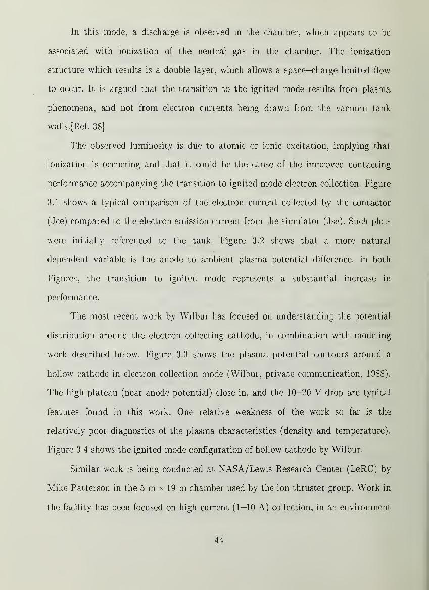
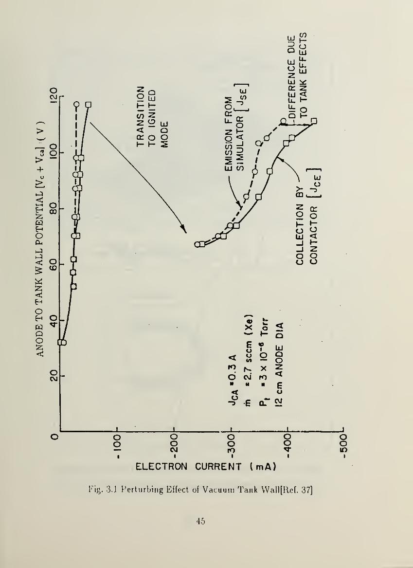
The observed luminosity is due to atomic or ionic excitation, implying that
ionization is occurring and that it could be the cause of the improved contacting
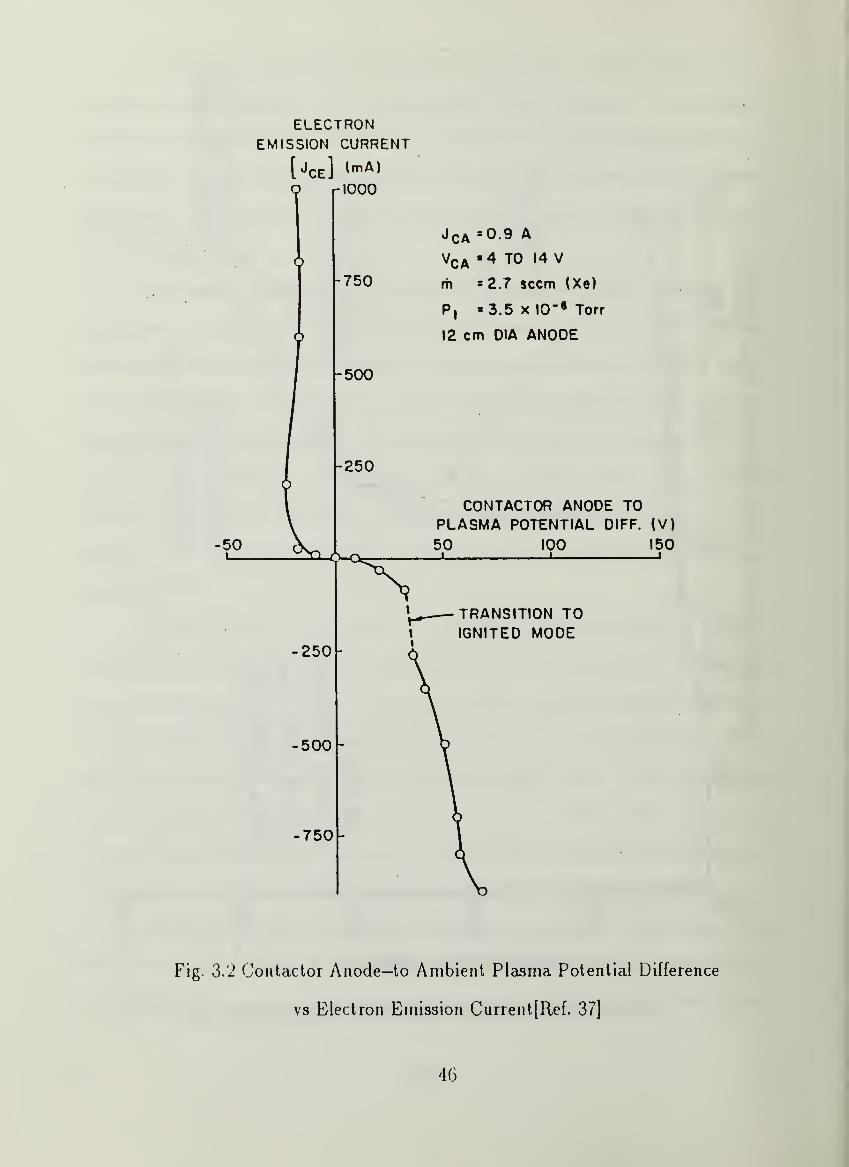
performance accompanying the transition to ignited mode electron collection. Figure
3.1 shows a typical comparison of the electron current collected by the contactor
(Jce) compared to the electron emission current from the simulator (Jse). Such plots
w^ere initially referenced to the tank. Figure 3.2 shows that a more natural
dependent variable is the anode to ambient plasma potential difference. In both
Figures, the transition to ignited mode represents a substantial increase in
performance.
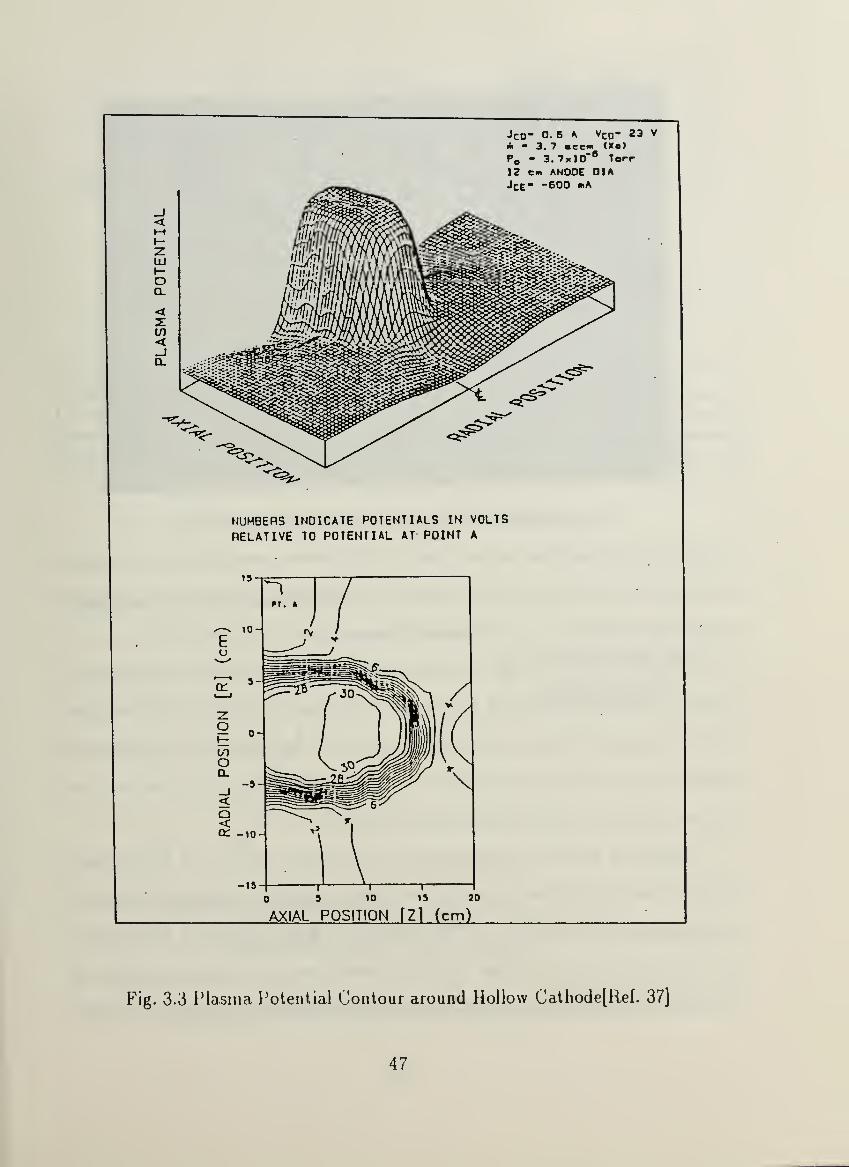
The most recent work by Wilbur has focused on understanding the potential
distribution around the electron collecting cathode, in combination with modeling
work described below. Figure 3.3 shows the plasma potential contours around a
hollow cathode in electron collection mode (Wilbur, private communication, 1988).
The high plateau (near anode potential) close in, and the 10—20 V drop are typical
features found in this work. One relative weakness of the work so far is the
relatively poor diagnostics of the plasma characteristics (density and temperature).
Figure 3.4 shows the ignited mode configuration of hollow cathode by Wilbur.
Similar work is being conducted at NASA/Lewis Research Center (LeRC) by
Mike Patterson in the 5 m x 19 m chamber used by the ion thruster group. Work in
the facility has been focused on high current (1—10 A) collection, in an environment
44
X o <
o
p<
Euuvt
«
g oo
ro r^ X 2-
•
O CJ m <N N H E< uo-3 •E qT CVJ
- -. . 1 « • t »
oo
ooCJ
I
oo
I
ooI
oolOI
ELECTRON CURRENT ImA)
Fig. 3.1 Perturbing Effect of Vacuum Tank VVall[Ref. 37]
45
ELECTRONEMISSION CURRENT
9 rIOOO
-750
•50I
-500
250
250
500
•750
JCA =0-9 A
VcA • 4 TO 14 V
fti » 2.7 seem (Xe)
P, «3.5 X \0-* Torr
12 cm DIA ANODE
CONTACTOR ANODE TOPLASMA POTENTIAL DIFF. (V)
50 100I
150—I
TRANSITION TOIGNITED MODE
Fig. 3.2 Contactor Anode—to Ambient Plasma Potential Dilference
vs Electron Emission Current[Ref. 37]
46
zLU
oQ.
<
<Q.
Jco- O. 6 A Vco- 23 V
ih •• 3. 7 seen (Xa>
Po - 3. 7»10'' Torr12 cm ANOOe OlAJcE" -600 KiA
NUMBERS INDICATE POTENTIALS IN VOLTS
RELATIVE TO POTENTIAL AT POINT A
AXIAL POSITION fZl (cm)
Fig. 3.3 Plasma Potential Contour around Hollow Cathode[H,ef. 37]
47

Fig. 3.4 Hollow Cathode Ignited mode Configuration
of relatively high ambient neutral density. Major effects were found due to volume
ionization caused by the collected electrons. Recent modifications of the chamber
will enable experiments at more reasonable neutral background levels.
Patterson's work focused on high current levels (higher than those studied by
Wilbur). Multiampere level (10 A) currents were extracted from the simulated space
plasma environment. Figure 3.5 shows the current to the plasma contactor with and
without power on for the contactor discharge, at comparable flows and bias
voltages. Relatively little difference is found. [Ref. 39]
Figure 3.6 shows the dependence of the collected current on the discharge
mode. Substantially higher currents are drawn in ignited mode. Comparison of
experiments of the CSU and LeRC facilities indicates the substantial dependence of
the results on the chamber size. Figure 3.7 shows the large variation in results for
similar operating conditions. Substantially large currents are possible in the LeRC
48

Current toplasna contactor,
A
100 200
Bias Uoltage, v
cc>nt»c tor f»{ III tv <»»tflow r«»« pref»vir« no.
- StCCA >'2.««-« (olid-tt0-i» !.««-« op»n-lt
- IS 1.4«-«
- «* «.««-«
A -SS S.9e-«
L - 39 C.»«-t
300
Tattno.
8Dac» PlasnaSinulator Plasna Contactor Sinulator
R«f ervncaContactorBias Pt.
Tvt>« txpell^n' Typ« erp»I Ian* rower
a a li/^" holw.11 1 ca«i>o<>«
ftr xeer>
• 4nk gro«jri<J ftnode
12 1 "ft M ye 6*f M H
Fig. 3.5 Current to Contactor vs Bias Voltages[H.ef. 39]
COLLECTED ELECTRON CUnHENT IJoJ. A
e
UN-IGNireO MODE
a IGtflTEO-nOOE
50 100 150 ?00 250
BIAS-TO-PLASMA POTENTIAL Dirr. (Vb-Vp). V
300
Fig. 3.0 Bias-t(>-Plnsrna Potential Difference[Ref. 39]
49

ELECTRONCOLLECTIONCURRENT «A
•04
•08
1.2
i.e
•t.o
CONTACTOR POTtWTIAL [Va-V^] |V)
40 BO 120 teo
JcD'OS TO OS A
\^0''0 TO 14 V
•h, •IS 7 teem (X«)
12 em ANODE OIA
too—
I
CSU rACILITY
P.'BxK)-* Torr
L«RC
rACILITY
P,» 2x10-* Torr
LeRC
CSUHe '>' <5 X 18E3/cn'^3He -" 8 X 10E8/cn'^3
Fig. 3.7 Current vs Contactor Potential
chamber, even tliougli the electron density (bias off) is substantially lower. Tiiis has
been attributed to the enhanced area of chamber walls capable of emitting
secondary electrons (Katz, private communication, 1988. Cohen, private
communication, 1988). The work at CSU and LeRC is continuing. One element of
the program proposed below is to conduct complementary experiments at Naval
Postgraduate School.
B. THEORETICAL STUDIES
Substantial theoretical work has been conducted under the NASA/LeRC
program, particularly by Dr. Dan Hastings (MIT), and the S-<:ubed group. Hastings
(1988) has addressed the plasma contactor problem at low earth orbit, as it might
apply to tethered systems, from an analytic viewpoint. This work focuses on the
micro—physical ])rocesses which will determine how well hollow cathode systems will
50
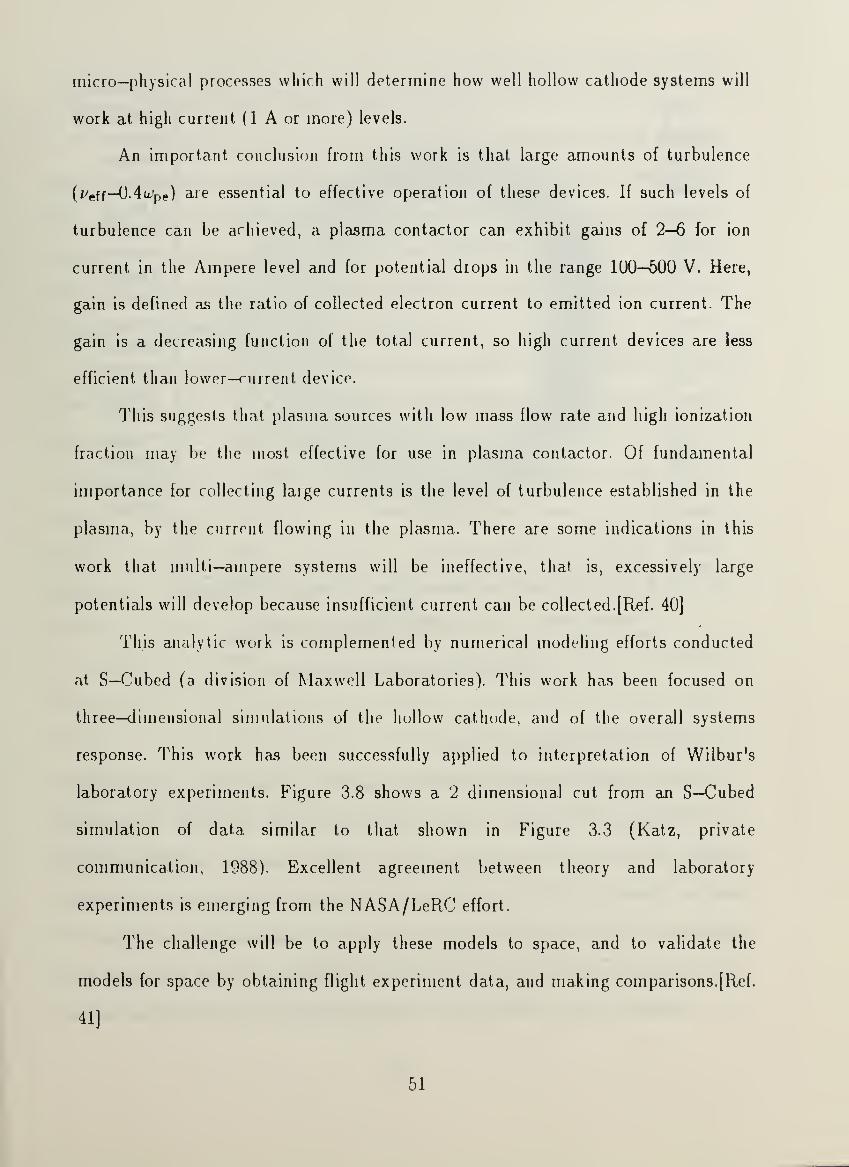
micro—i)hysical processes vvliich will determine how well hollow cathode systems will
work at high current ( 1 A or more) levels.
An important conclusion from this work is that large amounts of turbulence
(^'eff—0-4u.'pe) are essential to effective operation of these devices. If such levels of
turbulence can be achieved, a plasma contactor can exhibit gains of 2—6 for ion
current in the Ampere level and for potential drops in the range lUO—500 V. Here,
gain is defined as the ratio of collected electron current to emitted ion current. The
gain is a decreasing function of the total current, so high current devices are less
efficient than lower—current device.
This suggests that plasma sources with low mass flow rate and high ionization
fraction may be the most effective for use in plasma contactor. Of fundamental
importance for collecting large currents is the level of turbulence established in the
plasma, by the current flowing in the plasma. There are some indications in this
work that multi—ampere systems will be ineffective, that is, excessively large
potentials will develop because insufficient current can be collect ed.fRef. 40]
This analytic work is complemented by numerical modeling efforts conducted
at S—Cubed (a division of Maxwell Laboratories). This work has been focused on
three-dimensional simulations of the hollow cathode, and of the overall systems
response. This work has been successfully applied to interpretation of Wilbur's
laboratory experiments. Figure 3.8 shows a 2 dimensional cut from an S—Cubed
simulation of data similar to that shown in Figure 3.3 (Katz, private
communication, 1988). Excellent agreement between theory and laboratory
experiments is emerging from the NASA/LeRC effort.
The challenge will be to apply these models to space, and to validate the
models for space by obtaining flight experiment data, and making comparisons. [Ref.
41)
61
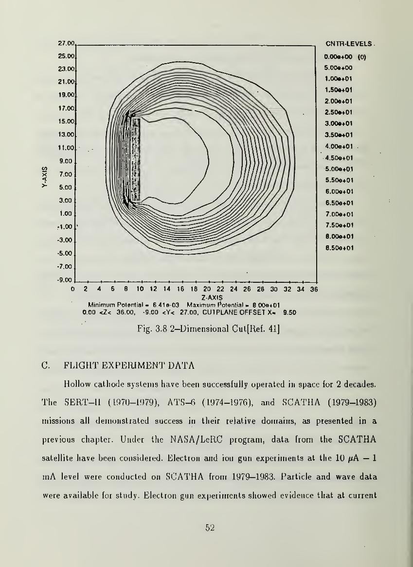
X<>-
8 10 12 14 16 18 20 22 24 26 28 30 32 34 36
Z-AXISMinimum Poierrtial - 6 41©-03 Maximum F^olential • 8 00«+01
0.00 <2< 36.00. -9.00 <Y< 27.00. CU7PLANE OFFSET X- 9.50
Fig. 3.8 2-Dimensional Cut[Ref. 41]
CNTR-LEVELS
O.OOtt-i^OO (0)
5.00«4^00
I.DOa+OI
1.5004^01
2.000401
2.50»401
3.00«401
3.50e401
4.009+01
4.50e401
S.OOe+OI
5.50O+01
6.009401
6.509401
7.009401
7.509401
8.009401
8.509401
C. FLIGHT EXPEIUMENT DATA
Hollow cathode systems have been successfully operated in space for 2 decades.
The SERT-11 ( L970-l!)79), ATS-(i (1974-1976), and SCATHA (1979-1983)
missions all demonstrated success in their relative domains, as presented in a
previous chapter. Under the NASA/LcRC program, data from the SCATHA
satellite have been considered. Electron and ion gun experiments at the 10 ^A — 1
mA level were conducted on SCATHA from 1979—1983. Particle and wave data
were available for study. Electron gun experiments showed evidence that at current
52

levels above 10 — 100 //A (roughly equal to the ambient thermal electron flux), the
beam was disrupted by space charge effects. [Ref. 42]
Charged particle data showed that the beam was causing heating of the local
electron population, and was failing to escape the satellite region. Recent studies
have shown that electron cyclotron waves may be the mediating factor. The
implications of this work are that electron beams are ineffective as "Plasma
Contactor". This conclusion is partially supported by shuttle observations, though
this remains somewhat controversial. [Ref. 43, 44]
Ion gun experiments on SCATHA showed a similar character, in that it was
found that the beam rapidly became space charge limited when high current (1 mA)
high voltage (1 kV) experiments were attempted. The satellite failed to charge to
the beam energy, indicating only 1—10 % of the beam escaped the near satellite
region. The ion gun was effective as a low energy plasma source, however, when
operated in "trickle mode". In this mode, it operates without accelerator voltage,
and resembles a large hollow cathode. In this mode, currents of lO's of //A could be
emitted, at coupling voltages of less than 1 V.[Ref. 21]
These "Plasma Contactor" experiments, and the earlier ATS—6 and SERT—II
data all indicate high levels of success with hollow cathode systems. There remains,
however, a need to further test hollow cathode systems, particularly in the high
current regime (Ampere level). From an operational point of view, the critical
question remains: Can 1 ampere of positive current be emitted from a hollow-
cathode in space ?
53
IV. EXPERIMENTAL FLIGHT PROGRAM
The natural extension of the ground—program conducted thus far is to conduct
a flight experiment which will extend our understanding beyond the limits of the 10
m chamber at NASA/LeRC. We intend to test the hollow cathode for its viability
as a plasma contactor with the specific application of a 1 A tether system.
This test will be a tethered, mother—daughter rocket payload, with hollow
cathode plasma sources on both ends. The experiment has been dubbed "HOCAT".
The payloads, as illustrated in Figure 2.2, would be instrumented in a way that
would allow us to determine the nature of the coupling between the hollow cathodes
and the ambient plasma, and the effects of driving positive and negative currents
through the system.
The mother payload will be recovered, and could be reflown with alternate
plasma contactor designs. Our goal at this time is to launch our first experiment in
mid 1991. Subsequent flights could occur at 1 year intervals, at substantially
reduced cost. In the following sections, the rocket, payload, and launch scenario for
this experiment, are described.
A. ENVIRONMENT
The plasma environment for the space shuttle and proposed space station is
sub—auroral at altitudes from 250—500 km. This environment is a cold dense
plasma, with temperatures of a few tenths of an electron volt (1000—3000 oK), and a
plasma density which ranges from 10^ particles/cm^ in shadow to 10^ particles/cm^
in sunlight. The lower ambient plasma densities provide the most severe test of the
54

plasma contactor performance, and we wish to focus the experiment on that limit.
The launch site would be Wallops Island, at the Wallops Flight Facility (WFF), in
order to insure a quiet geomagnetic environment. This eliminates the need to
disentangle artificial from natural processes, and provides access to substantial
ground resources (particularly the Millstone Hill incoherent scatter radar facility).
For the experimental region, the electron densities of daytime and nighttime
are shown in Figure 4.1 and 4.2. It is apparent from these two Figures that the
lowest ambient plasma density Ne we are likely to encounter in the 1991—1992
period (solar maximum) is the 10^ /cm^ level found at night. The neutral density in
this region is 10"/cm3, primarily Oxygen. This value can be compared to the neutral
density of 3.5xl0iVcm3 found in the CSU and NASA/LeRC chambers at lO'^ - lO'S
Torr. In the ionosphere, the neutral density is almost hundred times larger than the
electron density.
The neutral gas environment for a sounding rocket has density
N(neutral)>N(ambient) because of rocket outgassing. Figure 4.3 shows neutral
pressure data from SPEAR—1. Its apogee was 370 km and measured minimum
payload pressure was about lO"^ Torr. Until very late in the flight, outgassing
dominates the local (rocket) environment. [Ref 45]
Typical electron temperature and thermal velocity profiles are shown in Figure
4.4. These are important for determining the ambient electron current. Ion
temperature, average mass, thermal velocity are shown in Figure 4.5. These values
result in a Debye—length illustrated in Figure 4.6, and electron collision frequencies
and mean free paths as shown in Figure 4.7. These are important for determining
the potential distribution and collected currents. Expected values at solar
maximum, night, 500 km altitude, are a Debye length of 0.3 cm, mean free path of
about 600 m, and collision frequency of about 350 Hz. [Ref. 46]
55

lono
800
son
Km
400
200
PAVTIMt SOLAR MIN
J 1 I I I ml II I I I ml
SOLAR MAX.
\
\
J 1 1 1 1 1 III
I02
J—I I I 1 III
K'J I0« , 10'
ELECTRON DENSITY (rm'^i
10''
I I I I I III
10'
F\g. 4.1 Ionospheric Electron Density (daytirne)[Ref. 46]
1000
10* 10^
ELECTRON DENSITY (cm-J)
I I I I I Mill I I I I 1 1 III I I I I I ml L I 1 1 ml II I I 1 1 III
10^ 1010
10II
1017
1013
1014
TOTAL COLUMNAR CONTENT (cni'M2,
Fig. 4:2 Ionospheric Electron Density (nighttinie)[Ref. 46]
56
I

T-n—I
f1 1m I I
"1 iini I I1—I
im i t n—
r
|rni I I I—
I
\iiri I I I—
r
CD
OCDin ^^
inQ12;
oo oCO CJ^ en
oo
o
QWm
3W
o00C/1
oC\2
oCD
I
o PRESSURE (TORR)
Fig. 4.3 SPEAR-1 Neutral Pressure Data[R.ef. 45]
r '^

IDOO
I—I—I—I—1—I I—I—I—1—I I 1 I I I 1 I I I I 1 I I ' ' ' '
: Si,.- I*)., ??oo MOO
1 • 1 1
OtGRflSK
1 1 1 1 1
mil
1
08 1?
1
1'
1
0?0
1
0?< on
1
3?
1
Oi 10 1? II 16 18 70 0??
Fig. 4.4 Electron Temperature and Thermal Velocity[Ref. 46]
inno
800 -
6X
km
100 -
?00 —
\"^
% \ -^ /\ \ '^
— \ A, /\ \ /
-
VVt,
\K<--'-
1/\ 1 SOLAR "IN
' / \l^^
y ^^""^^^^^^r^..10
1 1
n » « » 60 V»/Vt
• 1 1 1 i 1 1 1 . 1 .
'
n JO
H 1 10"" K|
so 60
1 . . 1 i . 1 . .1
600
1 1
1100
OeCREESK
I.I?200
1 1
3000
1
1
001 0?
1
0) 01
kT, /• I»V)
1 . 1
OS
1
006
1
oo;
1
a ?00 400 (00 too 1000 i?uo IWO
Vti (V5)
Fig. 4.5 Ion Temperature, Mass and Thermal Velocity[Ref.46]
58

km
uuu/
/ \ 1 !-
/
// / '
800 — /
/
//v-^l// / /
600 ,^
/
/ / / // /
/ / / /'
/ / / /400 —
/ // /
-
\ CJ"^'
DAYTIME SOLAR
200 " JLMIN.'v<r /
- ^<\-r^nzizMAX.
n _t I 1 1 1 1 lij
—
. , 1 i 1 1. i ml ...1 i.-l i.LJLLL
0.1 l.O 10 100
DEBYE LENGTH (Aq) cm
I I' ' ' ' ' III r I I I I I III Ill
10* 105 10^ lO'
NUMBER OF ELECTRONS IN A OEBYE SPHERE
1000
800
600
Fig. 4.6 Debye Length[R,ef. 46]
SOLAR MIN vg
km
400 -
200
/
/ // fmlp SOLAR MAX / e^ip SOLAR MIN
/
J I I I I ml I I I I I m l I I I I I II il I t I i I ml I t I I I I II
10' W^ 10^ 10' 10'
m & Hi
Fig. 4.7 Election Collision Frecjuency and Mean Free Path[Ref. 46]
69

B. LAUNCH VEHK'LE
A Black Biaiit X lia.s been selerterl as the appropriate vehicle for launching the
HOCAT experiirient. This decision is based on the desire to reach 5U0 km altitude,
with an estimated payluad of 010 lb. Table 1 shows the rough allocation of weight to
payload comiionenls based on previous experience with tlie UAH-CRIT 1
experiment. As illustrated in Figure 4.8, this gives us a weight growth margin of
60-70 lb (e.g. 10 %). The Black Brant X outer diameter is 17.26 inches and length
is about 10 feet. The configuiation of the Black Brant X payload is shown in Figure
4.9.
v>KUJ
ZO
1200 -1
1100 -
1000 -
•00 -
•00 -
700 -
d eoo -
ooa.<
«» -
400 -
300 -
200 -
100 -
NASA SOUNDING ROCKET PERFORMANCE
TOMAHAWKTAURUS
NIKC \TOMAMAWKTOMAHAWK
TEMKie
BMANT
V
Sl>»tH
»»ACMtNIKE CAJUN
TAUMUSOMtON
MIKE OniON
•lACK lltANT V
ONIONANCAS
1 1 1 1 1 r100 300 300 400 SOO 600
100
I
300
—
1
\
300 400
PAYLOAD WEIGHT(KC)
—T"SOO 5S0
Fig. 4.8 NASA Sounding Rocket Performance
Ames
4 yn 1 1 1 1 1
—
TOO 800 900 1OO0 1100 1200
PAYLOAD WEIGHT IPOUNDS) .
3000
•00
60
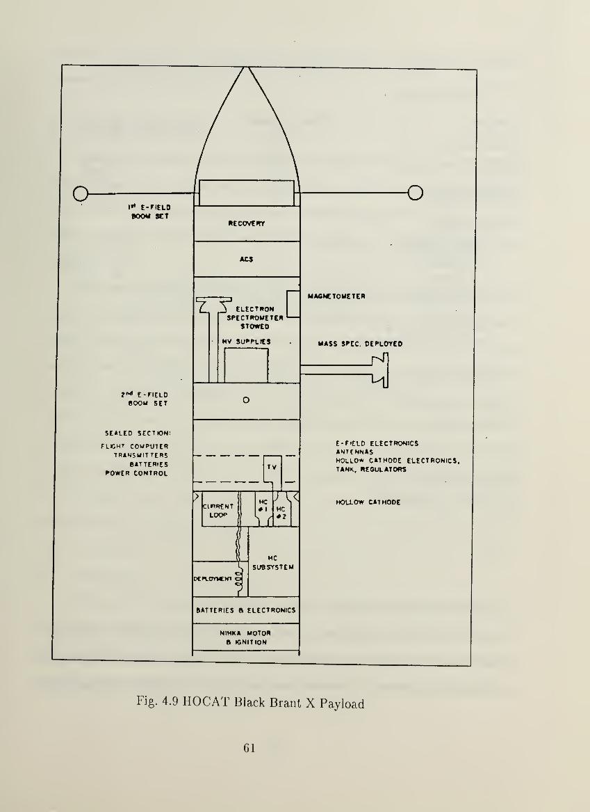
oI** E-riELOK>OU SCT
t"* t-riELOBOOM SET
SEALED SECTK5N:
fLCMT COMPUTERtR*NSMITTE»«S
BATTERIESPOWER CONTROL
Kcmznt
ACS
T 3^ ELECTfrRONSPECTROMETER
STOWtO
MV SUPPLIES
BATTERIES ft ELECTRONICS
NIHKA MOTORB ICNITION
MACNCTOMETen
MASS SPEC. OEPLOTEO
MJ
E-riELO ELECTRONICSANTCHNASHOLLOW CATHODE ELECTRONICS.TANK, REOULATOftS
HOLLOW CATHODE
Fig. 4.9 HOCAT Black Brant X Payload
61

TABLE 1 ALLOCATION OF WEIGHT AND POWER
Weight and Power
Section
Nose ConeBoom Set #1RecoveryRCSMagnetometerPlasma Analyzers
Weight(Pounds)20.
12.
89.
72.
1.
18.
Power(Watts @28 VDC)0.
0.
O.(self)
O.(self)
1.4
2.4
Scaled Section
Flight ComputerTransmitters(2)
TranspondersTV CameraE field electronics
Power Control
Batteries
Hollow Cathode # 1
electronics k plumbing
12.
4.
2.
1.
6.
4.
12.
21, _
18.
112.
12.
20.
5.
1.
0.
25.
Altitude Switches
(G—switch, relays, timers)
10. 8.4
Hollow Cathode # 1
Current Loop1.
8.
0.
4.
Structure, Cabling 225. 0.
Hollow Cathode # 2
Batteries & Power systemDeployment Mechanism
22.
8.
20.
25.
2.
0.
Nihka ignition k sep 43. 0.
Total 610. 244.
C. DEPLOYMENT SYSTEM
For the HOCAT experiment, the Canadian OEDIPUS Canadian deployment
system has been adopted as nearly ideal for our purposes. An initial separation
velocity of 1 m/s can be obtained by firing a gas jet for 10 seconds. The maximum
62
separation will \>c l(Jl) in at, about .S(JO km apogee. This is a reasonable separation
distance in the available time.
D. FLIGHT SCENAIUO
This rocket flight should provide about 11 minutes o{ flight time. The Nihka
motor burnout occurs at lUU second, as the lUU km mark is passed. Our operations
would begin at this point, with deployment of the booms, and the beginning of the
tether deployment. The Nihka motor will be jettisoned to reduce neutral gas
contamination.
We have tentatively selected a goal of reaching maximum extension of about
100 m at apogee, at about 8 minutes into the flight. On the downward leg, there
would then be b minutes of data before crossing the 100 m altitude mark, at which
time the tether would be jettisoned, and the recovery effort (for the mother
pay load) would begin. During the operation period, the currents to each satellite
would be determined, both for passive conditions, and with the packages actively
biased with respect to each other. The attitude of tiie tether line with respect to the
magnetic field will, of course, vary with time. Rotation of the tethered pair about
their center of mass will allow studies of current collection parallel and
perpendicular to the magnetic field line.
E. PAYLOAU
The proposed payload, and satellite, would largely be built and integrated at
UAH, with assistance from VVFF in key areas (In particular, machining deck plates,
and acquiring standard VVFF flight hardware such as transmitters). The main
satellite provides power, a basic telemetry system (i.e. transmitters and receivers),
63

at.titucle roiitrol, mid n niagiicloinptrr. Basic VVFF services include environmental
tests, launch, recovery, and ground telemetry-
1. Hollow (,'atliode
The core of the experiment is of course, the plasma source. We propose
to use the standard hollow cathode geometry, used previously on the SERT II and
ATS-6 ion engine experiments. Figure 4.1U and 4.11 illustrates the standard
features and size of the Hollow cathode respectively. Gas (we will use Xenon) is fed
SWAGED HEATERBARIUM ALUMINATE IMPREGNATEDPOROUS TUNGSTEN INSERT-
VAC
CATHODE ORIFICE^'k = 12 V
KEEPER ELECTRODE
-hli(^
Fig. 4.10 Hollow Cathode Design
HEATER WITH FOIL INSULATION
ROLLED TANTALUM FOIL ' ''^'""^
INSERT (R500 TREATMENT)
7 mm
rv
RING ANODE
5 mm
0.7 mm ORIFICE DIA
Fig. 4.11 Dimensions of Hollow Cathode
64
througli the erul of the rnUiode, i)a.ssing through Uie cylindrical device, with an arc
struck at the exit aperture. The porous tungsten insert provides a low work function
electron emitting surlarc, which is typically operated at about lUUO oC, with heat
supplied by an external heater. A typical cathode is 1/4" in diameter, and a few
inches long. One problem vvitli hollow cathode systems is contamination of the
barium insert by ambient atmosphere, and long startup sequences.
This problem is resolved by a vacuum enclosure around the cathode,
which is blown off after launch. Two designs have been considered for plasma
source. The first of the Hughes Research Laboratory design recently implemented
for the AF/Flight Model Discharge System (FMDS). This design is derived from the
successful SPIBS design flown on the SCATHA satellite. The second possible
supplier is SRS Inc, which provided a cathode system for Ihe recent SPEAR—
1
sounding rocket experiment.
2. Experiment Control and P(JM Encoder
The encoder system developed at UAH provides the facility not only to
collect and eiuode all data (analog and digital) into a high bit rate steam (751)
kbps), but also to intelligently control complex experiments, to store the data at
even higher bit rates (up to 1'2 Mbps) and to telemetry it back down to the ground
during less interesting intervals. Significant processing power exists within this
system (about 5U % of a VAX 780) so that on—board processing is convenient.
Instrument power at 28, +/—15, and +/->5 volts is provided. The output
of the encoder directly drives NASA standard S—band transmitters and is
compatible with all Wallops groimd facilities. This system has now completed three
successful space flights, the last being the CRIT I campaign whicli was one of the
most complex that Wallops has yet flown.
bb

A iiartinil'irly valuable aspect of the fast—event—analyzer (Figure 4.12)
is tlie "burst mode" capability—the ability to sample instruments at rates greater
than 1(J Mil/ lor J—J seconds. Tliis will be particularly useful for studying the
transient response of the system to changes in the bias voltage on the tether wire.
MEMoirr
BUSS(IS BIT)
PROCESSOR 32COI648 KWORDS E»PROM32 KWORDS RAM
< »
< >
RS232 LINKSERIAL LINKOlOrTAL CONTROL
H MEGABTTESSTATIC RAMNS 1024
DMA /SEQUENCER
C^^
lA) BUSS (8 BIT)
SLOW AMAJ.005«0 KSAMPLES/SEC
' ,52:a
>
FAST ANALOOS330 KSAMPLES/SCC
.IS
,21
SUPER- FAST ANALOGSIS MSAMPUS/SEC
.'6
,.2'
<:=:> POWER CONTROLDACS. DIGITAL
*/?'."«
7 . - -
LK—-P
c:
SPACECRAFT CONTROL-«—-6 BIT
12-BIT ANALOO CHANNELSDIGITAL BITSI6«BIT ACCUMULATORS
12-BIT ANALOO16-BIT ACCUMULATORS
B OR 9 BIT ANALOGIS- BIT ACCUMULATORS
16-BIT DIGITAL CONTROLSERIAL LINKSDAC OUTS
SERIAL LINKSERIAL LINK (<2)
DIGITAL CONTROL
Fig. 4.12 UAH Fast Event System
3. Electric Field Instruments
The electric field instrument consists of a pair of spherical double probes
on 3 m boom. The objectives of this experiment are to measure thermal electron
density and temperature, tlie plasma wave spectrum, electric fields, and to provide a
05

refprcnre j)r)iiit, iridirating payload iiol.eiit.inl. Two pairs of l)Oonis will be llown,
placed as far apart as practical on the main payload, oriented orthogonally. This
experiment desip,ii lias been siuxessfully used on numerous rocket experiments over
the last decade. When the instrument is operated in the Langmuii probe mode, the
spherical sensors are biased at fixed potentials relative to the plasma and the
current collected by the spheres is measured.
By allowing the probes to float with respect to the vehicle, information
about the payload potential can be obtained, and local electric fields can be
measured. High speed sampling of the electric field data (using the super—fast
channels of the flight computer) allow measurements at frequencies from 15 kHz to
10 NHlz, allowing us to watch for high frequency waves (e.g. electron plasma
waves). The low fiequency waves (0—15 kHz) for electric fields or ()n/n
measurements will be sampled directly, allowing for observations of turbulence in
the plasma, and key signals such as the lower hybrid resonance. One telemetry
transmitter would be dedicated to these "wideband" measurements.
Electric Held and density data from a recent flight from Sondre
Stromfjord, Greenland is shown in Figure 4.13. As can be seen, the plasma density
ranges from '2*10^ to about lU^ on a typical flight to 5UU km apogee.
4. Thermal Plasma Analyzer (Ions and Electrons)
The objective of this pair of instruments is to obtain measurements of
the distribution function of plasma ion components and electrons in as much detail
as practicable. This will require the use of instruments having differential response
in angle and energy, with energy coverage from a few eV to keV. The instruments
primary tasks are to determine the satellite potential accurately, and to watch for
nonthermal characteristics of the local plasma which indicate heating, or other
interesting plasma interactions. The detectors can characterize the density, and
G7

29.023 Ful I Fl ight DotottltM.M _.
Dans I \f
^^v\A 11* M^^*^^
n—I—I—I—I—
r
T—I—I—I—I—I—I—I—I—I—I—I—I—I—I—I—
r
Plaaito Fraquaner
ii'^iin^.Syl, I » »ww»^ »Vi
-t—I—I—I—
r
T—I—I—I—I—I—I—
r
T—I—I—I—I—I—I—
r
Zonal E Field
t MM .
*< tl.M«
e• isa.M
^^VrivYA^-^^^t.^^'^^ A J^iJ
1—I—I—I—I—I—I—I—I—I—I—
r
T—I—I—
r
T—I—I—I—I—I—
r
U*r idlonol t Plaid
Fig. 4.13 Electric Field and Density Data
temperature of the low energy core of the electrons and ions, and also the
supra-thermal features such as anisotropic heating or acceleration and conical
angular distributions which may arise.
The electron detector (Figure 4.14) is an electrostatic analyzer (ESA)
which the UAH group has successfully used on several rocket campaigns. It is a 2—
D
imaging spectrometer, covering the energy range from rear zero to 3 keV, with 10 %
energy resolution over that range. The ion detector is based on a modification of the
ESA, in order to include ma.ss resolution (Figure 4.15). This is done be adding a
toroidal magnet at the exit aperture of the ESA. It will have sufficient mass
resolution to separate H ,0"^, and Xe .
68

Fig. 4.14 Electrostatic Analyzer
TOROIDMAGNET
MASS SPECTROSCOPIC ESA
Fig. 4.1,"^) ESA Included Mass Resolution
The unusual capability of resolving extremely heavy ions will allow us to
separate locally generated ion distributions from the ambient ions. This is important
for making accurate determinations of negative payload potentials, and inferring
heating of locally emitted ions, such as Xe , The modification for mass analysis is
underway at UAH. Figure 4.16 shows ESA result from ATS—6 ion engine
experiment. This is a giey scale presentation of particle data, where the horizontal
69

80,000-
10,000 -
>^ 1000 ->-
ouUJ
100-
10 -
-
UCSD-ATS-6Day 292 of 1974
NS IONS0845-1000 UT
-20 200ROTATION ANGLE
Fig. 4.16 ATS-6ESA
'0

aocis is detector rotation angle on tlie ;^nxis—stabilized sparecraft, and the vertical
axis is ion kinetic energy. The third axis, Ilux, is presented as shades of grey, with
black corresponding to zero, or low counts. White, or light grey shaxdes correspond
to high [lux. I'his is seen at high energies (10—8U keV), and in the lower left hand
cornor(—!20o to +2(Jo, (j to 10 eV). This demonstrates the separation of local and
distant plasma by energy and arrival direction. Ions from the ion engine (charge
exchange) are found in the lower left hand corner. [Fief. 36]
Spectrometer results from the SPEAR—1 experiment using the basic (no
mass analysis) design are illustrated in Figure 4.17. The data arc from a period
where a small sphere deployed on a boom was biased 16 kV with respect to the
sounding rocket body. As a result, the rocket body was pushed 5 to 10 kV negative.
One—hall second hiter, the data from Figure 4.17 are found. The peak in
the ion flux from 3 to 4 keV indicate the detector (and rocket body) are charged to
—3 to —4 kV. These data illustrate how the ESA design can be used to infer satellite
potentials — a fundamental element of the mission. [R«f. 47]
6. Direct Current Mecisurements (Current Loop)
A major question to be addressed with this experiment is the question of
how the currents flow from the satellite, and parallel and jierpendicular to the
magnetic field lines, 'i'raditionally, currents are measured by using tiie observed
ambient particle distributions. We will be making such measurements.
Genrially, however, important portions of the ambient distribution
function are easily missed, either due to .satellite charging, or gaps on the angular
coverage. Hen( e energy and angle space are inadequately covered. In the proposed
mission, it would be highly desirable to have a direct measurement of current
density, several meters Iroin the satellite. A new technique for making such
measurements has beiMi developivl at UAH. The principle of the current loop

10^
xlO'-
X
bJ
10'-
10'
loi
INT. ENERGY P3 R) lEBfl (230.66.1)T 1—I I M I n r I I 1 1 n 1 1—I I I 1 1 1| I r—r-rrTTT
T—I—I"iT i 1 1 r
I02
1 1 1 I M TlI
SHEEP ENERGY (ELECTR0MVOLTS)
)
I I I I IT
iffi
Fig. 117 Spectrometer Results from SPEAR—
1
ineasureincut, illustraiccl in Figure 4.18, determines the (uireni tiirough a loop of
opticed fiber by measuring tlie P'araday rotation of polarized light propagating
around the fiber.
This tec hni(jue allows measurement of currents at frequencies up to a few
kilohertz and a sensitivity of a few microamps per square meter. It is impervious to
electromagnetic interference from the spacecraft, and measures the entire current
independent of the characteristics of the distribution function or the species that are
72

cnriying it, and is rclalively light, \v(Mglit and rugged. Tlic niirrnt loop will be
deployed appioxiuiately J—in iioni the niother paylo-ul.
POLARIZEDINPUT
a = v/HdT= v/j- dS
Fig. 4.18 Principle of the Current Loop Measurement
6. TV Caineia
A low—light level television camera has been included in the design (or
two reasons. The primary reason is to watch for visual aspects of the "ignited
73

mode", and to cJi'teiiiiinc Uic oLciit, of tlit* cHsrliaigc region aiound tlie electron
collecting snbsatcllitc. '1 lie second reason is to verily deplo\ jiient, and provide
ns(^condarv means of iiieasuiing the rockel—satellite separation. A standard
"off—the—shelf" caiiieia has been specified. Tlie size is lOU iiiiii x 47.5 mm x 50 mm
and weight is 11 (' giaiiis withnut lens. 'I'lu- suppli(M will he EEV, Inc.
7. Magnetomete r
Wallops Flight Facility will provide a (lux—gate magnetometer with a
resolution of about ](JU iiT that can be directly sampled on three—axes by the UAH
telemetry systein. This should be sufficient for attitude determination and the
detection of any large magnetic disturbances.
74
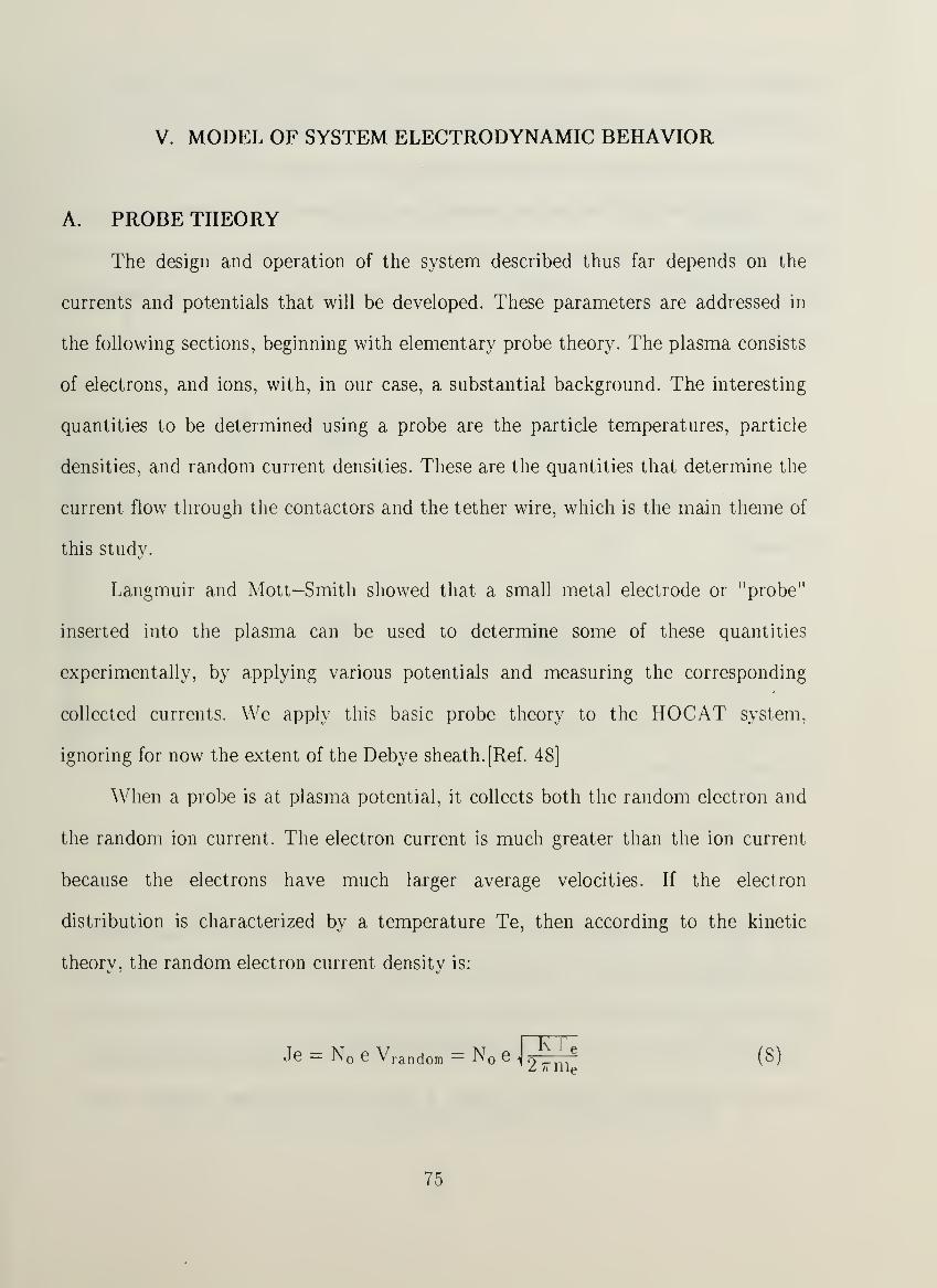
V. MODEL OF SYSTEM ELECTRODYNAMIC BEHAVIOR
A. PROBE THEORY
The design and operation of the system described thus far depends on the
currents and potentials that will be developed. These parameters are addressed in
the following sections, beginning with elementary probe theory. The plasma consists
of electrons, and ions, with, in our case, a substantial background. The interesting
quantities to be determined using a probe are the particle temperatures, particle
densities, and random current densities. These are the quantities that determine the
current flow through the contactors and the tether wire, which is the main theme of
this study.
Langmuir and Mott—Smith showed that a small metal electrode or "probe"
inserted into the plasma can be used to determine some of these quantities
experimentally, by applying various potentials and measuring the corresponding
collected currents. We apply this basic probe theory to the HOCAT system,
ignoring for now the extent of the Debye sheath. [Ref. 48]
When a probe is at plasma potential, it collects both the random electron and
the random ion current. The electron current is much greater than the ion current
because the electrons have much larger average velocities. If the electron
distribution is characterized by a temperature Te, then according to the kinetic
theory, the random electron current density is:
Je = No e Vrandom = No 6 |^-^ (8)2 TT nif
75

where Nq is density, e is electron charge, and vth is the average thermal velocity of
the electrons. Typical ionosphere values give J = 1 mA/m^ so to collect 1 A
(electron) current requires a conducting balloon whose radius is 12.6 m.
If we ignore the effect of the potential on the ambient plasma distribution (e.g.
Debye shielding), we can determine how the particle flux varies with potential. For
a negatively charged body, flux for the repelled electrons can be expressed as
follows:
Flux = No |^^^~^"It;^ - No l^^ (1 --^) (9)
where e(p > 0. The flux of electrons for an attractive potential can be expressed as
follows:"^ -- —
e
Flux = No \J^ e ^^f;^ = No Ir^^ (1 + -^) (10)
where e0 > 0. This expression for a collector with spherical geometry can be
expressed as follows:
Je-Nevth(l+-||^) (11)
where Je is current density, e is electron charge, vth is the average thermal velocity,
(f)is spacecraft potential, K is Boltzmann constant, and Te is electron temperature.
The total current collected to the outer surface of spacecraft is just 1= Je*Area. This
would be the main term for the positive end of the tether system, excluding plasma
contactor operations. Figure 5.1 shows a plot of the electron current density
76

which would bp rollertod at the positive end of a tether, in the absence of a plasma
source device, at thiec different altitudes. The model ionosphere values previously
illustrated were used here.
4-
300_km408 km
C4t.e
-T1 1
1. . .
11 1 1
\
1 1 1
1I 1 r5^ km
09a
t!
uaS(JV
• .a
^
J I I I I L I I I I 1 I L I I L
It
Positive Potential ( V )
Fig. 5.1 Plot of Electron Current Density vs Positive Potential
77
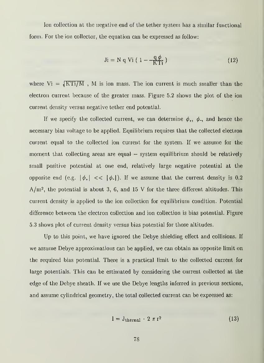
Ion collection at the negative end of the tether system has a similar functional
form. For the ion collector, the equation can be expressed as follow:
Ji = NqVi(l--|^) (12)
where Vi = \ KTi/M , M is ion mass. The ion current is much smaller than the
electron current because of the greater mass. Figure 5.2 shows the plot of the ion
current density versus negative tether end potential.
If we specify the collected current, we can determine 0+, <^-, and hence the
necessary bias voltage to be applied. Equilibrium requires that the collected electron
current equal to the collected ion current for the system. If we assume for the
moment that collecting areas are equal — system equilibrium should be relatively
small positive potential at one end, relatively large negative potential at the
opposite end (e.g. \(f)^\ << |0-|). If we assume that the current density is 0.2
A/m2, the potential is about 3, 6, and 15 V for the three different altitudes. This
current density is applied to the ion collection for equilibrium condition. Potential
difference between the electron collection and ion collection is bias potential. Figure
5.3 shows plot of current density versus bias potential for those altitudes.
Up to this point, we have ignored the Debye shielding effect and collisions. If
we assume Debye approximations can be applied, we can obtain an opposite limit on
the required bias potential. There is a practical limit to the collected current for
large potentials. This can be estimated by considering the current collected at the
edge of the Debye sheath. If we use the Debye lengths inferred in previous sections,
and assume cylindrical geometry, the total collected current can be expressed as:
I = Jthermal ' 2 ;r r2 (13)
78
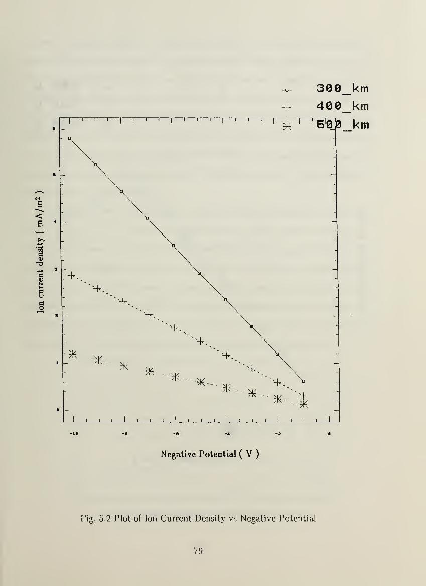
-f
T 1 1 1 1 1 1 1 1 1 1 1 1 1 1 1 1 1 r
frj
'
na
a
o
-f.
-^
30 0_km400_km5^ km
J i_ J I I I I I I I I I I I L
-4
Negative Potential ( V )
Fig. 5.2 Plot of Ion Curient Density vs Negative Potential
79

la
"T1 r 1 r "T
1 r
4-
"T r
380 k
4ee k
5'0l0 k
i«
oo
>
a
o
J I L J I L I ' '
• .a • .4 t.s ••
Current density ( A/m^ )
Fig. 5.3 Plot of Bias Potential vs Current Density
80
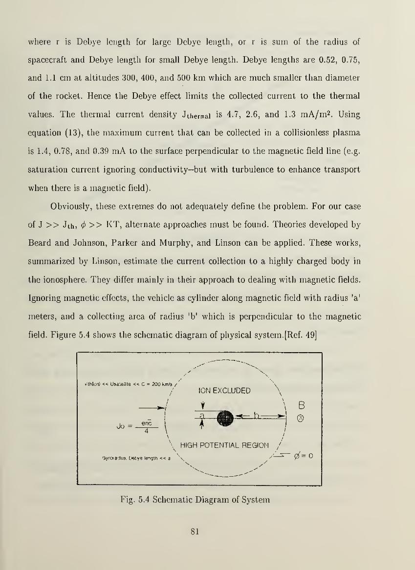
where r is Debye length for large Debye length, or r is sum of the radius of
spacecraft and Debye length for small Debye length. Debye lengths are 0.52, 0.75,
and 1.1 cm at altitudes 300, 400, and 500 km which are much smaller than diameter
of the rocket. Hence the Debye effect limits the collected current to the thermal
values. The thermal current density Jthermai is 4.7, 2.6, and 1.3 mA/m2. Using
equation (13), the maximum current that can be collected in a coUisionless plasma
is 1.4, 0.78, and 0.39 mA to the surface perpendicular to the magnetic field line (e.g.
saturation current ignoring conductivity—but with turbulence to enhance transport
when there is a magnetic field).
Obviously, these extremes do not adequately define the problem. For our case
of J >> Jth, </> >> KT, alternate approaches must be found. Theories developed by
Beard and Johnson, Parker and Murphy, and Linson can be applied. These works,
summarized by Linson, estimate the current collection to a highly charged body in
the ionosphere. They differ mainly in their approach to dealing with magnetic fields.
Ignoring magnetic effects, the vehicle as cylinder along magnetic field with radius 'a'
meters, and a collecting area of radius 'b' which is perpendicular to the magnetic
field. Figure 5.4 shows the schematic diagram of physical system. [Ref. 49]
\
»th«on} <«. Usdielllte << C = 200 km/3 /
ION EXCLUDED \
^Jo
enc 1
*
Xl\ B
\ HIGH POTENTIAL REGION
rSyrcracJius. Detye length << a \ 0=0/
Fig. 5.4 Schematic Diagram of System
81

The ratio between I and lo can be expressed in terms of the ratio between the radius
of the collecting area and the radius of the rocket as follows:
' =(^)^ (14)
where lo is thermal current, and I is collected current which is 1 A for this
experiment. The potential can be calculated in terms of —r- for the cases of spherical
space charge limit by equation (15) as follows:
= 34 a3 (-L )^ (15)Ao
Figure 5.5 shows the measured data from the SPEAR—1 experiment. This
ionosphere experiment shows the relationship between bias voltage and sphere
current, up to 40 kV, 0.2 A. The (positive) sphere potential is about 75 % of the
bias, the rocket body is about —0.25Vbias- These data suggest that the
(approximately) linear relationship of equation (15) can be applied to ionospheric
current collection.
If the magnetic field effects are partially included, as developed by Parker and
Murphy, the ratio —i- can be expressed by equation (16), which gives rise to a
"dynamic upper limit", as follows:
-[;<l + (^)' (16)
where 0o = 178*a2 for a typical magnetic field strength of 0.45 Gauss. To bridge the
gap between the magnetic field limited collection and space charge limited
82

O
c0)i_ —
-
1—13 Oooi_
Q. 9CO o
T 1 1r
V(kV) = 244 1(A)
1 r
286s MET
350km alt.
J I I u J I I 1_
30 40
Potential (kV)
Fig. 5.5 Sphere Current Data from SPEAR—
1
collection, Linson has developed a theory which deals with the magnetic field. The
ratio —I- can be expressed in terms of the potential by equation (17).
I 2001^- qc0o[ln(20/qc0o) - IJ
(17)
where qc is 1/4 — 1. Figure 5.6 shows the plot of —y- versus bias potential for
spherical space charge limit, dynamic upper limit, and the cylindrical model with
magnetic field. The radius 'b' of the collecting area is 5.8, 7.8, and 11 m for three
different altitudes above. Figure 5.6 shows the relation between radius and bias
potential so that the radius can be expressed as a function of potential. If we assume
that the potential is 100 — 200 V, the radius is 3.5 — 5.7 m.
For ion collection, first, the space charge limited current problem is similar so
that the area must be much larger. The radius is 45 m at 400 km altitude, which in
83
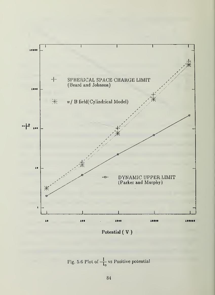
!••••
.*
!•••
+ SPHERICAL SPACE CHARGE LIMIT(Beard and Johnson)
w/ B field( Cylindrical Model)€
If
DYNAMIC UPPER LIMIT(Parker and Murphy)
!• !•• ite* itett t«tt*t
Potential ( V )
Fig. 5.6 Plot of —r- vs Positive potential"T^
84

"1 1 1 1 1 (\ \
( 1 f 1 1 1 r
24 _
£•
le
1—'—'—'—
r
12
J I 1 1 I II I I I I I I L J L
Radius = 2.253*10-2- (Bias Potential) + 1.173
Fig. 5.7 Plot of Radius vs Bias Potential
If
Potential ( V )
(X !••>
85
turn gives a higher potential of bout 8 kV. This does not include the important
effect of electron emission from rocket surfaces, due to secondary electron
production from the surface or nearby neutral gas (outgassing). This leads to greatly
reduced potentials. For the SPEAR—1 experiment, the illustrated bias potential was
40 kV and the reduced potentials 0+, 0- were ± 10 kV.
B. MODIFICATIONS DUE TO PLASMA CONTACTOR
The introduction of the plasma contactor has two effects. First, it is an
effective electron emitter. Therefore, the ion collection problem is eliminated. By
comparison with Wilbur's data (presented earlier), potentials of less than 100 V are
needed to extract Amperes of electrons. Second, the electron collection process is
enhanced. For the tethered satellite system, the potential difference between the
electron collector and electron emitter will be the potential that we have to apply
through the tether for the tethered rocket system.
1. Electron Emission
The theory for electron transport has been applied in simplified form to
electron emission to the space plasma. When the hollow cathode is used as a
electron emitter, the plasma density at distance R from the orifice can be expressed
as equation (lS):[Ref. 50]
R = ro (^rVP (18)
where Uq is produced electron density (about lO^^/cm^), ro is distance from the
orifice about 1 cm, and Uamb is lO^/cm^. For the collisionless plasma, there is an
effective collision frequency which determines the potential-current relation. It can
be expressed as follow:
86

U = Q Up (19)
where a is about 0.1, Wp is the plasma frequency {^Amc'^fm). The potential can then
be expressed in terms of known parameters as function of To:
M^o) = KTe ln(-i\) + 9xl0'0 -^^-^ i lii(-^) (20)namb io«^pV^o;-^ *'amb
A hollow cathode operating in the spot mode at a flow rate of 100 mA
equivalent, produces an electron density of about lO'^/cm^ at about 1 cm from the
orifice. For those values, the impedance is 23 Q. Therefore, the potential drop is 23
V for a 1 Ampere system.
2. Electron Collection
Electron collection can again be considered as a problem of establishing a
conducting plasma cloud, of sufficient radius to collect the required current. Figure
5.8 shows the plasma cloud expansion model. The three density regions are defined
here as the inner, collisional, higli density region (a few cm), a transition region (a
few m in radius), and "ambient" low density collisionless plasma. The diameter of
the collecting cloud is not changed from our previous discussion —only the necessary
potentials. The space charge limited condition has been relaxed by the addition of
positive space charge from the contactors. [Ref. 51]
The current potential relation can be estimated if we assume that there
is no magnetic effect, and the system is operating at constant current. The plasma
ions stream out across the sheath, canceling a portion of the electron space charge,
which is formed by the inward streaming electrons. The ratio of the theriiicd fluxes
in this case is just that due to the relative mobility.
87

o
v»
UJ
-J
o
It
3
t/i
V)
r.
.0^"
c
»« -
T aHI u
J
K
^
O -
§ HQ C/1
i9
XT
o
At
oI
i-l
I
CC
ooo
I
o
Io
Io
Fig. 5.8 Plasma Cloud Expansion ModelfPtef. 51]
88

.J. = ^4h-J- (21)
This relation is known as the "Langmuir condition" which is the basic
stability condition for a strong plasma double layer. At this ion current, the voltage
required to sustain a fixed electron current is reduced by one—third. If the
"Langmuir condition" ion current is exceeded where -^m/M*Ie < Ip < le, the
generated plasma remains quasineutral and the ions expand hydrodynamically. This
will lead to substantially reduced potentials. Theories developed by Parks and Katz
and Hastings indicate potentials of about 20-30 V for a of 0.2 are necessary to draw
1 Ampere current. Theoretical works by Dr. D Hastings have been investigating the
radius and gain for the ambient plasma to develop the function R = R((^).[Ref40]
C. SUMMARY
Relatively large (kilovolts) potentials are developed in ionospheric systems
driven to the Ampere level. For both the electron emitting and electron collecting
ends of the tethered satellite system, locally generated plasmas eliminate the space
charge sheath. The high voltages necessary to transport charge across a space charge
sheath makes the sheath regions the highest impedance portions of the tether
system. Reducing this impedance by local plasma sources will greatly enhance the
effectiveness of a tethered satellite system. Systems with hollow cathodes are
predicted to develop potentials of the order 10 V. This value is in contrast to
laboratory results which indicate that potentials of order 100 V were needed to
collect 1 Ampere electron current. The conclusion which results from these
estimates is that the primary energy range that the particle detectors should be
designed for is the 1 — lOO's of eV range, with at least some capability in the
kilovolts range.
89

VI. CONCLUSIONS AND RECOMMENDATIONS
This study has defined the the Hollow Cathode sounding rocket experiment
(HO CAT). The purpose of this experiment is to measure the coupling of large
currents (up to 1 A) from a satellite into the ambient plasma, and the nature of the
return path through the plasma. Two bodies will be deployed to approximately 100
m separation with Hollow Cathode subsystems mounted at both ends. The system
will be aligned along the geomagnetic field line during the initial deployment. The
practical deployment system for this rocket payload will be based on Canadian
OEDIPUS deployment system.
Laboratory and theoretical studies of Hollow Cathode performance have been
reviewed. Analysis suggests that for the HOCAT system to derive 1 A current, a
bias potential of about 30 V will be required. This bias estimate should be within a
factor of 3 of being correct. Hence, power system should designed to cycle the bias
from 1 to 100 V. Once the current reaches 1 A, the bias potential will be constant
(e.g. current limited operation).
Instrumentation will include particle detectors with with coverage up to 1 — 2
keV, and mass analysis for H"^, 0*, and Xe"". Hence, it will be possible to infer
negative potentials, and the nature of local plasmas accurately. Direct current
measurement can be made through the current loop of optical fiber by measuring
Faraday rotation of polarized light propagating around the fiber. This allows
measurement of currents at frequencies up to a few kilohertz and a sensitivity of a
few microamps per square meter. The langmuir probe will provide us with
measurements of thermal electron density and temperature, the plasma wave
90

spectrum, electric fields, and a reference point indicating payload potential. The
wave data will make possible to search for turbulence, and plasma heating
signatures in the VLF and HF frequency range.
The results of this experiment will enable us to understand how the the
Hollow Cathode works as a current source and sink. If we succeed in
emitting/collecting 1 A current, such subsystems can be applied to long tether
systems which can produce power up to MW level. Similarly, they can be employed
for experiments with large electron guns which require current balance. This
experiment should demonstrate the validity of theories previously developed for
laboratory work, or indicate which new physical processes must be included to
properly model charged particle beam and electrodynamic tether system.
91

LIST OF REFERENCES
1. Stuart, D. G., 4 Guidance Algorithm for Cooperative Tether-Mediated/Orbital Rendezvous, pp. 31—45, MIT, 1987.
2. Grossi, M. D., "Historical Background Leading to the Tethered Satellite
System (TSS)" AIAA 24th Aerospace Sciences Meeting, Reno. 6—9 January,1986.
3. Lang, D. L., and Nolting, R. K., Operation with Tethered Space VehiclesGemini Summary Conference, Manned Spacecraft Center, NASA SP—138,
1967.
4. Piland, R. O., and Penrod, P. R., Summary of the Gemini Program and Its
Effect on Manned Space Science, The seventh International Symposium onSpace Technology and Science, Tokvo. pp. 27—53, AGNE Publishing Inc.,
1967.
5. General Research Corporation Report 1545—03—88—TGM, SpringElectrodynamic Tether h'orkshop, by K. Kolecki, Section No. 2, 18—19 May,1988.
6. Facility Definition Team, Utah State University, Report NASA ContractNASS—33383, The Tethered Satellite System, by P. M. Banks, pp. 7—75, 23
April, 1980.
7. Sasaki, S., Oyama, K. I., Kawashima, N., Hirao, K., Obayashi, T., Raitt, W.J., Williamson, P. R., Bamks, P. M., and Sharp, W. F., "Results from a Series
of US/Japan Tethered Rocket Experiments", MSA/AIAA/PSN InternationalConference on Tethers in Space, 1986.
8. Maehlum, B. N., Denig, W. F., Egeland, A. A., Friedrich, M., Hansen, T.,
Holmgren, G. J., Maseide, M., Maynard, N. C, Narheim, B. T., Svenes, K.,
Torkar, K., Troim, J., and Winningham, J. D., "A High Current Electron
Beam Experiment on a Sounding Rocket from Andoya Rocket Range", The
8th ESA symposium on European Rocket and Balloon Programs and RelatedResearch, (EAS SP-270) SWEDEN, 17-23 May, 1987.
9. Obayashi, T., Kawashima, N., Kuriki, K., Nagatomo, M., Ninomiyo, K.,
Sasalci, S., Yanagisawa, M., Kudo, L, Ejiri, M., Roberts, W. T., Chappell,
C. R., Reasoner, D. L., Burch, J. L., Taylor, W. L., Banks, P. M.,Williamson, R.R., and Garriott, P. M., "Space Experiments with Particle
Accelerators", Science, Vol. 225, pp. 195-196, 1984.
92

10. Riedler, W., "Proposal for an Active Space Potential Control Experiment for
the STSP CLUSTER Mission Part 1: Scientific/Technical Plan", IWF,Austira, July 1987.
11. Hess, W. N., Trichel, M. C, Davis, T. N., WiUiam, C, Geggs, G. E., Kraft,
E. S., Stassinopoulos, E., and Maier, E. J.. "Artificial Aurora Experiment andPrinciple Results" Journal of Geophysical Research, Vol. 76, No. 25, 1971.
12. Winckler, J. R., "An Investigation of Wave Particle Interactions and Particle
Dynamics Using Electron Beams Injection from Sounding Rockets", SpaceScience Reviews 15 (1974), pp. 751-780, 1974.
13. Winckler, J. R., "A Summary of Recent Results under the ECHO Program for
the Study of the Magnetosphere by Artificial Electron Beams", Comic PhysicsTechnical Report 168, 1 September, 1976.
14. Sasaki, S., Kawashima, N., Kuriki, K., Yanagisawa, M., and Obayashi, T.,
"Vehicle Charging Observed in SEPAC Spacelab—1 Experiment", Journal ofSpacecraft, Vol. 23, No. 2, 1985.
15. Beghin, C, "Phenomena Induced by Charged Particle Beams", Science, Vol.
225, pp. 188, July 1984.
16. Olsen, R. C, "Experiments in Charge Control at GeosynchronousOrbit—ATS—5 and ATS—6", Journal of Spacecraft and Rocket, 1985
17. Getty, W. D., and Smullin, L. D., "Beam—Plasma Discharge: Buildup of
Oscillations", Journal of Applied Physics, Vol. 34, pp. 3421. 1963.
18. Israelson, G, A., and Winckler, J. R., "Effect of a Neutral N2 Cloud on the
Electrical Charging of an Electron Beam—Emitting Rocket in the Ionosphere:
ECHO IV", Journal of Geophysical Research, Vol. 84, No. A4, 1 April.
1979.
19. Grandal, B., '^Artificial Particle Beam in Space Plasma Studies", pp.3-33, Plenum Press., 1982.
20. Burch, J. L., "Space Plasma Phvsics Results from Spacelab-l", Journal ofSpacecraft, Vol. 23, No. 3, May-June 1986.
21. Watermann, J.,and Wilhelm, K., "Space Shuttle Charging or Beam—PlasmaDischarge: What Can Electron Spectrometer Observations Contribute to
Solving the Questions ?", Journal of Geophysical Research, Vol. 93. No. A5.
pp. 4134-4140, May 1988.
99 Kaufmann, R. L., Arnoldy, R. L., Moore, T. E., Kintner, P. M., Cahill Jr,
L. J., and Walker, D. N., "Heavy Ion Beam—Ionosphere Interactions: Electron
Acceleration", Journal of Geophysical Research, Vol. 90, No. AlO, pp.9595-9614, October 1985.
93
23. Moore, T. E., Arnoldy, R. L., Kaufmann, R. L., CahiU Jr, L. J., Kintner,P. M., and Walker, D. N., "Anomalous Auroral Electron Distribution Due to
an Artificial Ion Beam in the Ionosphere", Journal of Geophysical Research^Vol. 87, No. A9, pp, 7569-7579, September 1982.
24. STAR Laboratory, Stanford University, Report D131—1, Neiu Conceptsin Ionospheric Modification by Storey, L. R. O., Bank, P. M.,Eraser—Smith, A. C, Gilchrist, B. E., Barker, K. J., and Williamson, P. R.,
pp. 83-133, 1987.
25. Bausler, B., Tremnann, R. A., Bauer, O. H., Baerendel, G., Bush, R.,
Carlson, C. W., Theile, B., KeUey, M. C., Dokukin, V. S., and Ruzhin, Yu.Ya., "Observations of the Artificially Injected Porcupine Xenon Ion Beam in
the Ionosphere", Journal of Geophysical Research^ Vol. 91, No.Al, pp.287-303, 1 January, 1986.
26. Himter, R. E., and Bartlett, R. O., "Cesium Contact Ion MicrothrusterExperiment aboard Applications Technology Satellite (ATS—IV)", Journal ofSpacecraft and Rockets^ Vol. 6, 1969.
27. Gavrilov, F. V., Myasnikov, A. S., Zhadan, G. G., Orlova, G. S., and Strokin,
M.V., "Some Results of Flight Tests of an Ion—Engine Model Using Surface
loniztion of Cesium on Tungsten", Kosmicheskie Issledovaniya, Vol. 11, No.
1, pp. 140—144, January—February 1973.
28. Byers, D. C, and Staggs, J. F., "SERT-II Thruster System Ground Testing",
AUA 7th Electric Propulsion Conference, Paper 69—235, 3—5 March, 1969.
29. Kerslake, W. R., Goldman, R. G., and Neiberding, W. C, "SERT-II Mission,
Thruster Performance, and In—Flight Thrust Measurements", AIAA 8th
Electric Propulsion Conference, Paper 70—1125, 31 August—2 September,
1970.
30. Jones, S. G., Staskus, J. V., and Byers, D. C, "Preliminary Results of
SERT-II Spacecraft Potential Measurements Using Hot Wire Emission
Probe", NASA TM X-2083 1970.
31. Kerslake, W. R., and Finke, R. C, "SERT-II Hollow Cathode Multiple
Restarts in Space", AIAA 10th Electric Propulsion Conference, 31
October-2 November, 1973.
32. Kerslake, W. R., and Finke, R. C, "SERT-II Thruster Space Restart", AIAA
nth Electric Propulsion Conference, 19—21 March, 1975.
33. Kerslake, W. R., and Domitz, S., "Neutralization Tests on the SERT-IISpacecraft", AIAA 14th International Electric Propulsion Conference,
Princeton, N. J. AIAA paper 79-2064, 30 October-1 November, 1979.
94

34. Kaufman, H. R., "Plasma Physics Analysis of SERT-II Operation", NASACR-159814, January, 1980.
35. Sasaki, S., Kawashima, N., Kuriki, K., Yanagisawa, M., and Obayashi, T.,
"Neutralization of Beam—Emitting Spacecraft by Plasma Injection", Journal
of Spacecraft, Vol. 24, No. 3, May-June, 1986.
36. Olsen, R. C, "Modification of Spacecraft Potential by Plasma Emission",Journal of Spacecraft and Rockets, Vol. 18, pp. 462, 1981.
37. Lewis Research Center Annual Report, Advanced Electric Propulsion andSpace Plasma Contactor Research, by P. J. Wilbur, Colorado State
University, NASA CR 175119, January, 1986.
38. Wei, R., and Wilbur, P. J., "Space—Charge—Limited Current Flow in aSpherical Double Sheath", Journal of Applied Physics, Vol. 60, pp. 2280,
1986.
39. Patterson, M. J., "Plasma Contactor Laboratory Characterization",
Electrodynamic Tether Meeting, General Research Corporation, 18 Mav,1988.
40. Hastings, D. E., "The Theory of Plasma Contactors Used in the Ionosphere",
Journal of Spacecraft and Rockets, in press, 1988.
41. Davis, V. A., Katz, I., Mandell, M. J., and Paris, D. E., "Three—DimensionalSimulation of the Operation of a Hollow Cathode Electron Emitter on the
Shuttle Orbiter", NASA/AII/PS^ International Conference on Tethers in
Space 17—19 September, 1986.
42. Olsen, R. C, "Electron Beam Experiments at High Altudes", Journal ofElectrostatics, Vol. 20, pp. 43-57, 1987.
43. McPherson, D. A., and Schober, W. R., "Spacecraft Charging at HighAltudes: The SCATHA Satellite Progrm", Progress in Astronautics andAstronautics, Vol. 47, "Spacecraft Charging by Magnetospheric Plasma",edited by A. Rosen, pp. 15-30, AAIA, NY, NY, 1976.
44. Katz, I., Jongeward, G. A., Parks, D. E., Reasoner, D. L., and Purvis, C. K.,
"Energy Broadening Due to Spacecharge Oscillations in High Current Electron
Beams", Geophysical Research Letter, Vol. 12, pp. 64, 1986.
45. Raitt, W. J., Burt, D. A., Berkey, F. T., Jost, J., Kelley, M. C, Pickett, J.,
Torbert, R., "A Sounding Rocket Payload to Study High Voltage CurrentCollection from the Ionosphere at Low Earth Orbit (LEO) Altitude", AIAA26th Aerospace Sciences Meeting, 13 January, 1988.
46. Michael, Kasha., Ionosphere and Its Interaction with Satellites, Gordonand Breach, pp. 7-71, 1969
95
47. Foley, T. M., "SDI Suborbital Launch Yields Data for High-power PlatformDesign", Aviation Vetk and Space Technology, 1987
48. Reitz, J. R., Miiford, F. J., and Christy, R. W., Foundations ofElectromagnetic Theory, Addison—Wesley Series in Physics, June 1980.
49. Linson, L. M., "Current—Voltage Characteristics of an Electron—EmittingSatellite in the Ionosphere", Journal of Geophysical Research, SpacePhysics Vol. 74, No. 9, 1 May, 1969.
50. Parks, D. E., and Katz, I., Theory of Plasma Contactors for ElectrodynamicTethered Satellite Systems", Journal of Spacecraft, Vol. 24, No. 3,
May-June 1984.
51. McCoy, J. E., "Plasma Motor/Generator Reference System Designs for Powerand Propulsion", MSA/AIAA/PSN International Conference on Tethers in
Space, 18, September 1986.
I
96
INITIAL DISTRIBUTION LIST
No. Copies
1. Defense Technical Information Center 2
Cameron Station
Alexandria, VA 22304-6145
2. Library, Code 0142 2
Naval Postgraduate School
Monterey, CA 93943-5002
3. Physics Library Code 61 1
Department of Physics
Naval Postgraduate School
Monterey, CA 93943-5000
4. Department Chairman, Code 61 WH 1
Department of Physics
Naval Postgraduate School
Monterey, CA 93943-5000
4. Professor R. C. Olsen Code 61 OS 10
Department of Physics
Naval Postgraduate School
Monterey, CA 93943-5000
5. Professor S. Gnanalingum Code 61 GM 1-
Department of Physics
Naval Postgraduate School
Monterey, CA 93943-5000
6. Maj. Yoon, Sang II 2Postal Code 138-150Gangdong Gu, Bang-i Dong, Samik APT 201-1103Seoul, Republic of Korea
7. Maj. Han, Hwang Jin 1
SMC 2402Naval Postgraduate School
Monterey, CA 93943-5000
8. Maj. Kim, Jong Ryul 1
SMC 1659
Naval Postgraduate School
Monterey, CA 93943-5000
97
9. LT. Commander. Youn, Duk SangSMC 1254
Naval Postgraduate School
Monterey CA 93943-5000
10. Lee, Yong MoonMa-Po Gu, Yun-Nam Dong, 382-17Seoul, Republic of Korea
11. Cpt. Song, Tae Ik
SMC 2686Naval Postgraduate School
Monterey, CA 93943-5000
12. Mr. Joe Kolecki
NASA/Lewis Research CenterMS 302-121000 Brookpark RdCleveland, OH 44135
13. Dr. Roy Torbert __^Physics Department
^
Universitv of AlabamaHuntsville, AL 35899
14. Cpt. Ryu, Jong SuSMC 2039Naval Postgraduate School
Monterey, CA 93943-5000
15. Library, P.O Box 2
Korea Military AcademvPostal Code 130-09Gong—neung Dong, 556—21 Dobong GuSeoul, Republic of Korea
16. Library, P.O Box 2
Postal Code 140-01
Yongsan Gu, Yongsan DongSeoul, Republic of Korea
98


3^y-s^?


='"dy and
Thesis
Y5273c.l
YoonDefinition study and
model for a tethered
sounding rocket.
