authentication system depend on hand … 28th volume/6zainab.pdf · · 2014-09-17traditional...
TRANSCRIPT
International Journal of Information Technology and Business Management 29
th August 2014. Vol.28 No.1
© 2012-2014 JITBM & ARF. All rights reserved
ISSN 2304-0777 www.jitbm.com
74
AUTHENTICATION SYSTEM DEPEND ON HAND GEOMETRY
USING BACK PROPAGATION NEURAL NETWORK
1 Dr. Firas M. M.. Al-Fiky, 2 Zainab Salih Ageed
1 IT & Network center, Duhok Polytechniq University, DPU // Iraq
2 IT department, Zakho Technical Institute, DPU // Iraq
Email: 1
[email protected] , 2 [email protected]
Abstract
In this method, the hand geometry measurement be used and a new features has been extracted
from two landmarks determined at the first step of preprocessing . The images taken by scanner
covered by a black box without peg. The data collected and then the pre-processing applied on
it, after that passed to feature extraction stage. Each person has its own features like finger
length, finger width, palm width, angle value and many other measurements. Features extraction
contain 20 distances for fingers and palm (D1-D20) and 10 angels values measured and
determine the center point on it . The angels calculated for a ten triangles determined, then
calculate the Area and the Perimeter on it. The second part of the proposed method begin with
training a neural network. The BPNN used here with trainlm algorithm after that testing the
NN. The population size was 100 samples, for 10 person, each person have 10 samples. For
Training set 70 samples taken and 30 for testing the NN. The Recognition Rate (RR) was 91%.
Keywords: Biometrics, Hand Geometry, Identification, ANN, Neuron
1. INTRODCUTION
The biometric word refer to the life-measure.
Biometric used in access control applications and
security depending on many properties. Biometric
technologies are defined as “automated method of
identifying or authenticating the identity of a living
person based on physiological or behavioral
characteristic” in the science and technology that
measuring and analyzing biological data [1].
With the development of ever increasing
technological systems that require authentication,
personal identification has become an absolute
necessity. With decreasing personal contact among
the people, the utilization of technical means for
personal identification is increasing. Everything from
the bank ATM to the internet requires some form of
passwords. Passwords however have their own
weaknesses; not only weak passwords can be easily
guessed but the strong ones can be broken through
too. It is recommended that people should not use the
same password for two different applications and
should change them regularly. In the modern world
that would mean memorizing a large number of
passwords. even access cards and identify cards can
be easily stolen or forged. More and more crimes
related to password and card thefts are being reported
every day. These problems are not trivial and new
International Journal of Information Technology and Business Management 29
th August 2014. Vol.28 No.1
© 2012-2014 JITBM & ARF. All rights reserved
ISSN 2304-0777 www.jitbm.com
75
means of authentications are not trivial and new
means of authentications which are more user
friendly and less prone to be duplicated is required
[2].
The use of biometrics as a reliable means
meeting the security concerns of today‟s information
and network based society cannot be belittled.
Biometrics is being used all over the globe and is
undergoing constant development[3]. The human
identification system using image processing has
been used in many application and fields of security
[4]. As a method of biometric recognition, hand-
shape recognition has always been recognized as an
effective means of personal identification [5].
A human body posses several physiological
characteristics that can serve as biometric features.
Also a human being develops several unique
behavioural traits which can also serve as biometric
features. The various physiological characteristics
that are generally used are face, iris, fingerprints,
palmprints, hand geometry and voice. Face is the
biometric primarily used by human beings to
recognize each other. This makes it an obvious
choice for biometric. The difficulty however is in the
fact that the biometric system has to rival the
complexity of the human brain. Fingerprints have
also been used for quite some time now and have
established its value as a biometric. The challenge
now is to develop more advanced systems which can
process partial prints and speed up the matching
process. The behavioral characteristics include
signature, handwriting analysis, voice, keystroke
pattern and gait. Signatures and handwriting have
been used extensively as biometrics. However they
have been used only as offline biometrics, i.e. no data
is collected during the process of signing or writing.
Automated biometric systems by including data
obtained during these processes vastly improve the
accuracy of the system [6].
At present, applications of biometrics are
rapidly increasing due to inconveniences in using
traditional passwords and physical keys. Hand
geometry, one of the most well-known biometrics, is
implemented in many verification systems with
various feature extraction methods[7].
The commercialization of hand geometry
dates to the early 1970s with one of the first
deployments at Georgia University in 1974. The US
Army began testing hand geometry for use in
banking in 1984. These deployments predate the
concept of using the geometry of a hand for
identification. The first commercial device for hand
geometry identification was made in 1994 [8]. The
hand identification systems are widely implemented
for their ease of use, public acceptance and
integration capabilities [9]. Hand geometry has
become a very popular access control biometrics
which has captured almost a quarter of the physical
access control market [10].
Hand geometry based identification
systems utilize the geometric features of the hand like
length and width of the fingers, diameter of the palm
and the perimeter. Hand geometry depend on human
hand, the human hand does not significantly change
after a certain age. Unlike many other biometrics.
The human hand is not unique therefore it considered
as a life measure. The hand recognition systems are
accurate for the verification purposes when combined
with other features and measurements of fingers and
hands [11].
2. Literature Survey
In 2005, Marcos F. and Guillermo M. [2] built a
database of 22 people using a conventional document
scanner. There system consist of a study about the
discrimination capability of different extracted
features, and the identification rate using different
classification based on neural network. Some features
removes and based only on 9 features per image, with
Nearest Neighbor Classifier (mse) the rate was 73.64
% and with Radial Basic Function 90 %.
In 2007, Varchol P., and Levický D. [16], proposed
a method to show the possibilities of using hand
geometry as the biometric characteristics by using
Hamming distance, Euclidian distance, and Gaussian
Mixture Model (GMM). The system was tested on
408 hand templates, depending on FAR and FRR
values. While in the same year, Saraf Ashish [2*]
proposed a verification system which is utilizes the
geometric features of the hand like length and width
of the fingers, diameter of the palm and the perimeter
for user authentication. The system accepts a
grayscale handprint from which it extracts the finger
lengths, finger widths and perimeter. The system
produces an excellent accuracy.
International Journal of Information Technology and Business Management 29
th August 2014. Vol.28 No.1
© 2012-2014 JITBM & ARF. All rights reserved
ISSN 2304-0777 www.jitbm.com
76
In 2008, Osslan O. And others [8], present the
identification system using Discrete Wavelet
Transform . An input image of a hand was obtained
using a scanner; the image is pre-processed and
transformed to the wavelet domain. In the wavelet
domain, 31 hand geometry features were obtained,
after that, the input image is tested against 120
images of hands stored on a database. The stage of
classification is performed using a simple nearest
neighbour algorithm with Euclidean distances,
Finally, a total recognition rate of 70.2 % was
obtained after experimental evaluation.
In 2009, Wei Chang W. And others [1], use the same
value FAR and FRR as the measurements of the
system but based on morphology, the experimental
results show that 0.0035 % and 5.7692% for FAR
and FRR respectively. In the same year another
research done by Vit N. [7], proposed a novel hand
geometry verification system that exploits DTW
distance measure and R-K band learning to further
improve the system performance. The evaluation
reveals that the proposed system outperforms the
current system by a wide margin, in terms of False
Acceptance Rate (FAR), False Rejection Rate (FRR),
and Total Success Rate (TSR) at Equal Error Rate
(EER).
In 2010, Lingming S. And others [5], presented
hand geometry recognition method based on
Gaussian mixture model (GMM) which used 1-D
centroid distance series to describe 2-D hand
geometry. Each departed finger obtained one centroid
distance series, which was used to build a Gaussian
mixture model and applied to hand geometry
recognition.
In 2011, another research done by Zena N.[11], proposed a system developed to identify and verify
persons and adopted to identify groups in the
principle of closed systems and to identify groups in
the principle of open systems. It is also show the
difference between the two principles. , The
recognition rate is more than 90% when adopted
principle of closed systems.
Recently in 2013, Nidhi Saxena, Vipul Saxena, and
others[6]; demonstrates a study about personal
verification and identification using hand geometry
consists of the lengths and widths of fingers and the
width of a palm. Users can place their hands freely
without the need for pegs to fix the hand placement
with six different distance functions were tested and
compared on 96 samples.
3. Aims of Thesis:
The aims of this work can be summarized by
the following points:
1. Building an efficient and easy offline
identification system that firstly extracting the
features from the hand image automatically.
2. Perform the matching process with hand
image returned from database.
3. Training an artificial neural network (ANN)
for recognition with minimum mean squared
error (MSE) and a high performance goal.
4. Biometrics:
The word “biometrics” comes from the
Greek language and is derived from the words bio
(life) and metric (to measure)[16], Biometric access
control are automated methods of verifying or
recognizing the identity of a living person on the
basis of some physiological characteristics, such as
fingerprints or facial features, or some aspects of the
person's behavior, like his/her handwriting style or
keystroke patterns. Since biometrics systems identify
a person by biological characteristics, they are
difficult to forge [17, 28].
Physical: Acquiring physical biometric samples
involves taking a bodily measurement from
subjects. This does not necessarily require any
specific action by the subject [18].
Behavioral: Acquiring behavioral biometric
samples requires subjects to be active. They
must perform a specific activity in the presence
of a sensor. A behavioral trait is learned and
acquired over time rather than based on biology.
Also, it is possible that behavioral biometric
systems will be developed with a design
constraint whereby the system “learns”
deviations in behavioral traits over time [19].
Figure (1) shows the main types of
biometrics with examples of each one [11].

International Journal of Information Technology and Business Management 29
th August 2014. Vol.28 No.1
© 2012-2014 JITBM & ARF. All rights reserved
ISSN 2304-0777 www.jitbm.com
77
Alphonse Bertillon, chief of the criminal
identification division of the police department in
Paris, developed and then practiced the idea of using
a number of body measurements to identify criminals
in the mid-19th century and others [12], These
biometrics or characteristics are tightly connected to
an individual and cannot be forgotten, shared, stolen
or easily hacked. The biometric information security
is one information security mechanism, which is
powerful than conventional cryptography system.
The biometric system plays a vital role in person
recognition. The main reason of biometry is so
popular in security, because there is no risk if
something might be lost or stolen in case of
traditional IDs and passwords [16]. The
characteristics can uniquely identify a person,
replacing or supplementing traditional security
methods by providing two major improvements:
personal biometrics cannot be easily stolen and an
individual does not need to memorize passwords or
codes. Since biometrics can better solve the problems
of access control, fraud and theft, more and more
organizations are considering biometrics a solution to
their security problems [13]. Geometric
measurements of the human have been used for
identity authentication in a number of commercial
systems[14].
The qualities of a good biometric are [21] :
1. Uniqueness: Two distinct person cannot have
same characteristics.
2. Universality: Every person must have
characteristics.
3. Permanence: Time invariant characteristics.
Figure 1. Basic Types of Biometrics with examples for each type[23]

International Journal of Information Technology and Business Management 29
th August 2014. Vol.28 No.1
© 2012-2014 JITBM & ARF. All rights reserved
ISSN 2304-0777 www.jitbm.com
78
4. Performance: Accuracy, speed and robustness of
technology used.
5. Acceptability: Indicates to what extend people
are willing to accept biometric system.
Sometimes high uniqueness comes at the cost of
lower acceptability due to more complex
acquisition, association with criminal
investigation and privacy issues.
6. Collectability: This characteristic can be
measured quantitatively. Usually biometrics with
high collectability also show high acceptability.
7. Circumvention: Ease of use of substitute. It
should be impossible for imposters to defraud the
biometrics system. For some biometrics such as
signature or face is hard to achieve.
4.1 The Mechanism of Biometrics Work
Before discussing the biometric
technologies, firstly, the fundamental operating
principles behind biometric systems should be
clerifyed. As in centuries past, biometric technology
today relies on two fundamental mechanisms
• Authentication and
• Identification.
The objective of authentication is to
determine if a particular person is who she or he
claims to be, for instance to cash a check.
Identification systems, by contrast, capture a person's
biometric information, say at an airport boarding
gate, and then compare it with templates stored in a
database looking for a match. Authentication systems
often require active participation by the individual
[27].
4.1.1 Authentication Systems
The general process for authentication
systems is outlined in Figure (2). The authentication
process starts with, for example, an individual
inserting a smart or magnetic card into a reader
(instead of a card, the user may key in his or her
username). If it is a smart card, the reader reads .
A biometric template from the card.
Otherwise, the reader reads the username.
Afterwards, the user's live biometric information is
captured and compared with the template either read
from the smart card or obtained from the database. If
the system determines that the individual is who she
or he claims to be, access is granted. Otherwise,
access is denied. While the authentication process
looks like today‟s common security systems,
biometric systems differ in several respects.
1- Biometric information captured from the
individual attempting to use the card serves as a
means of verifying that the person attempting to
use the card is the person to whom the card was
issued.
2- People cannot forget biometrics as one might a
PIN.
3- Biometrics is unique for each person.
4.1.2 Identification Systems
Identification systems are either passive to
the individual (they can be used without the user‟s
knowledge) or are active (they require the individual
to provide biometric data, that is they require active
cooperation from the user). An example of a passive
identification system would be a surveillance system
at a stadium entrance that automatically captures face
images of entering sports fans with the help of a
digital camera. The face images captured are then
passed to a computer that attempts to find a face
match in a database containing face images of
previously arrested violent fans. In this hypothetical
example, the “troublemakers” are being identified
passively.
An iris recognition system installed near the
entrance to an airport is a hypothetical example of an
active identification system. A security guard may
ask entering passengers to look into an iris
recognition device. The iris image obtained is
compared with iris images in a database that contains
iris images of people with a criminal record or people
whose personal background may indicate an
inclination to terrorism. If a person is identified as
such, more thorough search procedures may be
applied to him or her before the person boards a
plane. In this hypothetical example, criminals are
being identified actively, that is they are made aware
of the identification [11][27].

International Journal of Information Technology and Business Management 29
th August 2014. Vol.28 No.1
© 2012-2014 JITBM & ARF. All rights reserved
ISSN 2304-0777 www.jitbm.com
79
4.2 Biometrics Technologies
There are many of biometrics used for
personal identification, where the effectiveness of
different biometric systems depending on how and
where it is used. Before implementing a system,
organizations evaluate the strengths and weaknesses
of each biometrics modality [18]. Biometric
technologies are available today that can be used
in security systems to help protect assets. Biometric
technologies vary in complexity, capabilities, and
performance and can be used to verify or establish a
person‟s identity. Biometric technologies have been
used in federal applications such as criminal
identification, and border security [23]. The
following are all key factors for selecting a biometric
system [15]:
Figure 2 Biometrics authentication algorithm[27]

International Journal of Information Technology and Business Management 29
th August 2014. Vol.28 No.1
© 2012-2014 JITBM & ARF. All rights reserved
ISSN 2304-0777 www.jitbm.com
80
Ergonomics
Throughput needs
User consideration
Evaluating the environment
Population size and demographics
Interoperability with existing or
planned systems
4.2.1 DNA Matching
Chemical Biometric The identification of an
individual using the analysis of segments from DNA
[20]. Deoxyribonucleic acid (DNA) is the one-
dimensional (1–D) ultimate unique code for one‟s
individuality except for the fact that identical twins
have identical DNA patterns. It is, however, currently
used mostly in the context of forensic applications for
person recognition. Three issues limit the utility of
this biometrics for other applications[21].:
1) Contamination and sensitivity: it is easy to steal
a piece of DNA from an unsuspecting subject
that can be subsequently abused for an ulterior
purpose.
2) Automatic real-time recognition issues: the
present technology for
DNA matching requires cumbersome chemical
methods (wet processes) involving an expert‟s
skills and is not geared for on-line non-invasive
recognition.
3) Privacy issues: information about
susceptibilities of a person to
certain diseases could be gained from the DNA
pattern and there is a concern that the
unintended abuse of genetic code information
may result in discrimination, e.g., in hiring
practices .
4.2.2 Face Recognition
It is one of the oldest roads, as everyone can
recognize those who know him just by looking at
their faces, and is based on taking the dimensions
between the members of the face and the general
shape of it, and can identify if the owner of the face is
alive or not, and that demand him to the work, such
as smiling or blinked his eyes and the system
compares the image picked up by what is stored has
to come out the decision of whether the person is
alive or not even if that person is authorized or is it
just an intruder or impersonator for a personal
authorized [22].
4.2.3 Ear Shape
This type of biometrics is used in legal
applications, as the form of permission and twists
characteristics and dimensions vary from one person
to another, where the use of this type appeared in
control of the applications of recently accessed [23].
4.2.4 Voice Recognition
This type of biometrics integrates between
physiological characteristics and behavioral
characteristics distinctive to the individual where that
sound is influenced in psychological Members
primarily basis as there are other factors which have
the effect of an actor in the properties of the sound,
where it is possible to change our voice depending on
the state of society around us, as well as the

International Journal of Information Technology and Business Management 29
th August 2014. Vol.28 No.1
© 2012-2014 JITBM & ARF. All rights reserved
ISSN 2304-0777 www.jitbm.com
81
environment an important role , your voice at home is
different from the voice at work. [24].
4.2.5 Fingerprint
One of the oldest methods of identification
of a person is the oldest systems of the mechanism to
know him was using a fingerprint, which began to be
used (Since the sixties of the last century [16].
4.2.6 Signature Recognition
Can count this type of biometrics is a study
of the dynamic characteristics of where the electronic
signature collecting data on several factors,
including: the amount of pressure on the pen, writing
direction, angle of the pen during the signing, the
speed of the signing, along the lines of signature and
number. The signing does not compare to the form of
e-signature, but also combines other data relating to
the signing of a way [23].
4.2.7 Iris Recognition
Consists of the colored part on the borders
of the pupil (the pupil is the black circle in the center
of the eye) of meanders vary from one person to
another, even among twins, and even appointed one
person to the other eye and has a high accuracy
outweigh the DNA, and is the automated systems to
identify the iris of the eye of faster and more accurate
systems at the moment. They can be compared to six
million image through just one second [11*] .
4.2. 8 Speaker Recognition
Differences in how different people‟s voices
sound result from a combination of physiological
differences in the shape of vocal tracts and learned
speaking habits. Speaker recognition technology uses
these differences to discriminate between speakers
[26].
4.2.9 Retina Recognition
Imprint retina works on the distribution of
the veins on the retina, and the retina is the part that
lies upon images from the lens of the eye. This
technique is based on a test of the retina where
includes an analysis of the layer of blood vessels
behind the eye and can be scanning the web very
accurate, but requires the user to focus and extend the
consideration of a specific point within the vessel and
this is not very convenient if the user is wearing
glasses or worried about the direct solicitation tool
reading [15].
4.2.10 Palm print
Palm print verification is a slightly different
implementation of the fingerprint technology. Palm
print scanning uses optical readers that are very
similar to those used for fingerprint scanning, their
size is, however, much bigger and this is a limiting
factor for the use in workstations or mobile devices
[25].
4.2.11 Hand Shape Recognition
Hand geometry systems have been in use for
almost 30 years for access control to facilities
ranging from nuclear power plants to day care
centers. Hand geometry technology takes 96
measurements of the hand, including the width,

International Journal of Information Technology and Business Management 29
th August 2014. Vol.28 No.1
© 2012-2014 JITBM & ARF. All rights reserved
ISSN 2304-0777 www.jitbm.com
82
height, and length of the fingers; distances between
joints; and shapes of the knuckles [26].
There are other types of biometrics, such as
fingerprint and nail the rhythm of walking, also said
that there is a trend towards the imprint of teeth and
many other fingerprints.
Table (1) show the quality of good biometrics as
been mentioned in the paragraph 2 between some
technologies [12].
4.3 Biometric Application
In the present era.. which has become
depends largely on the technology in all areas and
with increased security gaps in protection systems
and the increasing attempts at fraud and electronic
fraud, an increased need and clearly to the use of
protection systems with a high degree of safety in
personal check, can be said that the protection
systems based on the use of biometrics in
authentication of personal user gives a high degree of
safety compared to other methods of personal
documents [10].
Table 1. A comparisons between some technologies according to the guality factor [29]

International Journal of Information Technology and Business Management 29
th August 2014. Vol.28 No.1
© 2012-2014 JITBM & ARF. All rights reserved
ISSN 2304-0777 www.jitbm.com
83
The application that uses the bioinformatics can be
divided into three main types:
1. Commercial applications: such as e-
commerce, access to the Internet and
networking in general, credit cards, access
real (physical) of the buildings, medical
records, distance education, and many
others.
2. Government applications: such as national
identity card, driving license, passport.
3. Judicial applications: such as the
verification of the identity of the bodies,
investigate crimes, identify the required
security, validation ratios, and find out the
identity of missing children [12].
4.4 The Advantages of using Biometric
There are several reasons led to the use of
biometrics, including[26] :
• They provide the appropriate reliability and easy to
use, where there is nothing to lose met or oblivion.
• The need to increase the reliability of a strong and
this is what biometrics technologies provided more
than other techniques.
• Low cost, making it suitable for use in commercial
fields.
• Suitability for government organizations, factories,
so many public organizations at the present time
resorted to use these techniques .
• Ability to use remote where it can be used via the
Internet, it does not require any spatial presence.
• Speed in the verification of a person because most
of the Biometrics are automated so the verification
process is usually very quick, and in most cases take
only several seconds.
• Difficult to counterfeit and the inability to guess, as
it is often difficult to falsify biometric, as it excels is
not possible to guess or predict.
4.5 The Disadvantages of using Biometrics
Biometric systems has their advantages, but
at the same time there are some negativities,
including [30]:
The possibility of errors during the
recording of biometrics or during matching.
Inconvenience person and harassment.
The need for user education and training.
Persons resistance to this type of technology
and non-acceptance of their application.
Loss of stored information that is obtained
from biometrics, and calls for the provision.
So, the protection is very important here.
The existence of personal considerations,
cultural and religious, where the floor to
suggest some criminal conduct, and the fear
of the privacy of the person, because the
information is not collected from the person,
but a gathering of his body.
Loss of body parts such as a finger or hand,
or lack thereof basically like parties.
Misuse of the data that have been obtained
using biometrics for purposes other than that
recorded for it.
Biometrics systems subjected to attack.
Fingerprinting can also be vital, for
example, from a dead person taking the
fingerprints of a dead person.
4.6 The Work of Biometric
Biometric technology varies in complexity,
capability, and performance, but all share several
elements. Biometric identification systems are
essentially pattern recognition systems. They use
acquisition devices such as camera and scanning
devices to capture images, recordings, or
measurements of an individual‟s characteristics and
computer hardware and software to extract, encode,
store, and compare these characteristics. Because the
process is automated, biometric decision-making is
generally very fast, in most cases talking only a few
seconds in real time [32]. Figure (2.3) shows the
generic biometrics-based system [34].

International Journal of Information Technology and Business Management 29
th August 2014. Vol.28 No.1
© 2012-2014 JITBM & ARF. All rights reserved
ISSN 2304-0777 www.jitbm.com
84
All biometric system involve similar processes that
can be divided into two distinct stages: enrollment
and verification or identification [32].
4.6.1 Enrollment
In enrollment, a biometric system is trained
to identify a specific person. The person first
provides an identifier, such as an identity card. The
biometric is linked to the identity specified on the
identification document. He or she then presents the
biometric (e.g., fingertips, hand, or iris) to an
acquisition device. The distinctive features are
located and one or more samples are extracted,
encoded, and stored as a reference template for future
comparisons. Depending on the technology, the
biometric sample may be collected as an image, a
recording; or a record of related dynamic
measurements. The biometric systems extract
features, encoding and store information in the
template is based on the system vendor‟s proprietary
algorithms. Template size varies depending on the
vendor and the technology. Template can be stored
remotely in a central database or within a biometric
reader itself; their small size also allows for storage
on smart cards or tokens [32].
The quality of the template or templates is critical in
the overall success of the biometric application.
Because biometric features can change over time,
people may have to re-enroll to update their reference
template [33].
4.6.2 Verification
In verification systems, the step after
enrollment is to verify that a person is who he or she
claims to be (i.e., the person who enrolled). After the
individual provides whatever identifier he or she
enrolled with, the biometric is presented, which the
biometric system captures, generating a trail template
that is based on the vendor‟s algorithm. The system
then compares the trial biometric template with this
person‟s reference template, which was stored in the
system during enrollment, to determine whether the
individual‟s trial and stored templates match [32]
Verification is often referred to as 1:1 (one-
to-one) matching. Verification systems can contain
Figure 3. Generic biometrics-based system [34]

International Journal of Information Technology and Business Management 29
th August 2014. Vol.28 No.1
© 2012-2014 JITBM & ARF. All rights reserved
ISSN 2304-0777 www.jitbm.com
85
databases ranging from dozens to millions of
enrooled templates but are always predicated on
matching an individual‟s presented biometric against
his or her reference template. Nearly all verification
systems can render a match-no-match decision in less
than a second. A system that requires employees to
authenticate their claimed identities before granting
them access to secure building or to computers is a
verification application [11][32].
In identification systems, the step after
enrolment is to identify who the person is. Unlike
verification systems, no identifier need be provided.
To find a match, instead of locating and comparing
the person‟s reference template against his or her
presented biometric, the trial template is compared
against the stored reference templates of all
individuals enrolled in the system. Figure (4) show
the typical stages of biometric recognition system
[37]. Identification systems are referred to as 1:N
(one-to-N, or one-to-many) matching because an
individual‟s biometric is compared against multiple
biometric templates in the system‟s database [32].
Figure 4.Typical Stages of Biometric Recognition
System
4.7 Hand Geometry
Hand geometry is based on the fact that
nearly every person‟s hand is shaped differently and
that the shape of a person‟s hand does not change
after certain age. Hand geometry systems produce
estimates of certain measurements of the hand such
as the length and the width of fingers. Various
methods are used to measure the hand. These
methods are most commonly based either on
mechanical or optical principle [24]. Hand geometry
is based on the palm and fingers structure [16].
4.8 Hand Anatomy
The human hand has a complex anatomical
structure consisting of bones, muscles, tendons, skin,
and the complex relationships between them .
Analysis of human hand anatomical structures is
important in various fields, including ergonomics,
hand surgery, as well as computer animation.
The bones of the hand are grouped into
three areas: digital, carpal, and wrist. The digital
bones of four fingers consist of distal, middle, and
proximal phalanges with distal interphalangeal (DIP),
proximal interphalangeal (PIP), and metacarpal
phalangeal (MCP) joints. The digital bones of the
thumb consist of the distal and proximal phalange
with the interphalangeal (IP) and carpometacarpal
(CMC) joints. The carpal bones are a set of eight
small bones, and the wrist bones are the radius and
ulna. Figure (5) shows the human hand anatomy of
the bone anatomy [11].
Figure 5. Bone anatomy[11]

International Journal of Information Technology and Business Management 29
th August 2014. Vol.28 No.1
© 2012-2014 JITBM & ARF. All rights reserved
ISSN 2304-0777 www.jitbm.com
86
In biometrics, not only the anatomical features but
also the mechanical joints of the hand are important.
Several methods are suggested to define the
mechanical joints. The axis of rotation between two
bones is defined as a line that does not move in
relationship with either bone while the bones move
around each other. On other hand, the mechanical
joint centers of the hand have been anatomically
estimated as the center of curvature of the head of the
bone proximal to the given joint. Figure (6) show the
surface anatomy of the human hand
Figure 6. Surface anatomy[39]
The three palmar skin regions are the palm,
fingers, and thumb. The palm region has three main
crease. The proximal palmar crease starts from the
silhouette edge of the hand near the haed of the
metacarpal bone of the index finger and runs through
the hollow of the pal. The distal palmar crease starts
from the head of the metacarpal bone in the little
finger and runs through the hollow, passing the head
of the head of the metacarpal bone of the ring and
middle finger. The thenar crease is located between
the proximal palmar crease and distal wrist crease
longitudinally [39]. Figure (7) show the creases of
palm and fingers.
Figure 7. Palm creases and fingers [11]
a) Meandering green: show folds rest palm,
b) Blue lines: showing the location of the
folds of the fingers,
c) Blue dots: showing the location of the
joints.
4.9 The Reasons of Choosing Hand Geometry
People may wonder about what is the most
effective biometric measurement? Frankly, there is
no ideal one since each biometrics has its own
strengths and limitations which the suitability of
particular biometric to certain application depends
upon several different factors explained in paragraph
2 and listed in table 1. The user acceptability in this
system seems to be most significant comparing to
other biometrics. In the meantime, more sophisticated
techniques have emerged yielding extremely low
EER (e.g., iris recognition systems), however hand-
based features are still one of the most common
biometrics used today.
Hand geometry-based authentication is also
very useful for various purposes. Almost all of the
working populations have and exception processing
for people with disabilities could be easily designed.
Hand geometry measurements are really easy to
collect based on table (2.1) that been explained in
paragraph 2.4. This is because the method of sensing
is relatively simple which does not require high
International Journal of Information Technology and Business Management 29
th August 2014. Vol.28 No.1
© 2012-2014 JITBM & ARF. All rights reserved
ISSN 2304-0777 www.jitbm.com
87
technology device. Unlike fingerprint imaging
system and a special illumination setup is needed by
iris or retina-based identification system [40].
5. Artificial Neural Network (ANNs)
The ANN usually called “neural network”
(NNs), are basically massive parallel computational
or mathematical models that tries to simulate the
structure and/or functional aspects of biological
neural networks [40]. ANN is a form of artificial
intelligence (AI) and the most powerful tools for
pattern recognition through a learning process,
growing, and adapting within dynamic environments.
It works by creating connections between
mathematical processing elements, called neurons.
Knowledge is encoded into the network through the
strength of the connections between different
neurons, called weights, and by creating groups of
neurons that work in parallel [41].
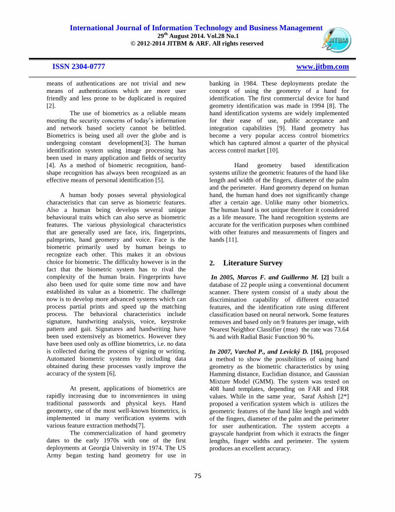
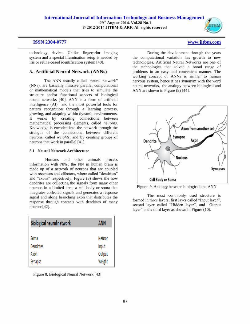
5.1 Neural Network Architecture
Humans and other animals process
information with NNs; the NN in human brain is
made up of a network of neurons that are coupled
with receptors and effectors, where called “dendrites”
and “axons” respectively. Figure (8) shows the how
dendrites are collecting the signals from many other
neurons in a limited area; a cell body or soma that
integrates collected signals and generates a response
signal and along branching axon that distributes the
response through contacts with dendrites of many
neurons[42].
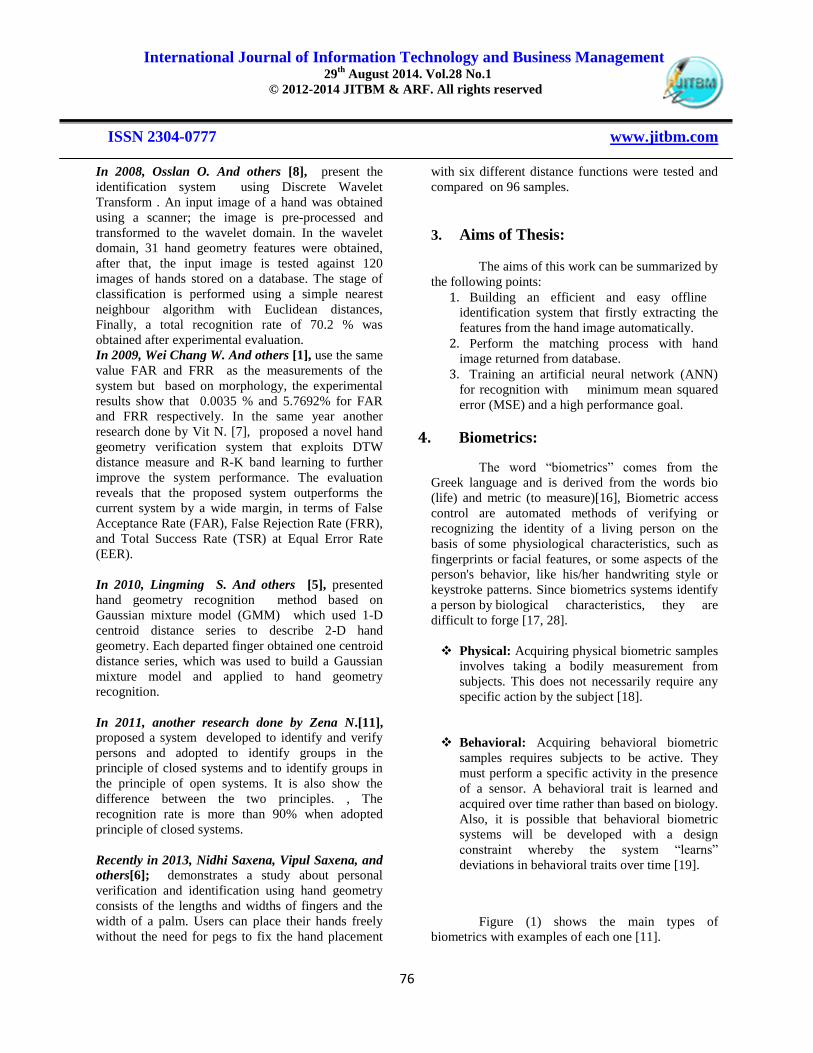
During the development through the years
the computational variation has growth to new
technologies, Artificial Neural Networks are one of
the technologies that solved a broad range of
problems in an easy and convenient manner. The
working concept of ANNs is similar to human
nervous system, hence it has synonym with the word
neural networks, the analogy between biological and
ANN are shown in Figure (9) [44].
Figure 9. Analogy between biological and ANN
The most commonly used structure is
formed in three layers, first layer called “Input layer”,
second layer called “Hidden layer”, and “Output
layer” is the third layer as shown in Figure (10).
Figure 8. Biological Neural Network [43]

International Journal of Information Technology and Business Management 29
th August 2014. Vol.28 No.1
© 2012-2014 JITBM & ARF. All rights reserved
ISSN 2304-0777 www.jitbm.com
88
The nodes of the input layer are passive, this
mean that there is no change or it does not modify the
data. The input layer receives a single value on their
input, and duplicates the value to their multiple
outputs. In comparisons, the nodes of the hidden and
output layer are active. This means there is
modification of the data. Each value from the input
layer is duplicated and sent to all of the hidden
nodes. This is called a fully interconnected structure.
The values entering a hidden node are multiplied by
weights, a set of predetermined numbers stored in the
program the weighted inputs are then added to
produce a single number. Before living the node, this
number is passed through a nonlinear mathematical
function like a sigmoid function. That is, the input
to the sigmoid is a value while its output can only be
between 0 and 1[41].
ANN has been shown to be an effective as
computational processors for task including [40] :
1. Pattern recognition
2. Associative recall
3. Classification
4. Data compression
5. Modelling
6. Forecasting
NNs are used for pattern recognition
application such as hand geometry recognition.
Back propagation can be considered as one of the
best neural models among many types of neural
models. Normally, only feed forward networks are
used for pattern recognition. Feed forward means
that there is no feedback to the input. Similar to the
way that human beings learn from mistakes, neural
networks could learn from their mistakes by giving
feedback to the input patterns [43].
5.2 Mathematical Model of a neuron
A neuron is an information processing unit
that is fundamental to the operation of an NN.
Generally the three basic elements of the neuron
model as follows and shown in Figure (11) [41]:
Figure 10. ANN architecture

International Journal of Information Technology and Business Management 29
th August 2014. Vol.28 No.1
© 2012-2014 JITBM & ARF. All rights reserved
ISSN 2304-0777 www.jitbm.com
89
1. Set of synapses each of which is characterized by
a weight or strength of its own. Specifically, a
signal ax at the input of synapse j connected to
neuron K is multiplied by the synaptic wkj . it is
important to make a note of the manner in which
the subscripts of the synaptic weights wkj are
written. The first subscript refers to the neuron in
question and the second one refers to the input
end of the synapse to which the weight refers.
The weight wkj is positive if the associated
synapse is excitatory; it is negative if the synapse
is inhibitory.
2. An adder for summing the input signals, weighted
by the respective synapses of the neuron.
3. An activation function for limiting the amplitude
of the output of a neuron.
A neuron receives several signals from its
input links, computes a new activation level and
sends it as an output signal through the output links.
The input signal can be raw data or outputs of other
neurons. The output signal can be either a final
solution to the problem or an input to other neurons.
The neuron determines its output by computes the
weighted sum of the input signals and compares the
result with a threshold value. If the net input is less
than the threshold, the neuron output is 1. But if the
net input is greater than or equal to the threshold, the
neuron becomes activated and its output at trains a
value 1. The neuron uses the transfer or activation
function [41] .
In mathematical terms, a neuron k can be
represented as shown in the following pairs of
equations [41] :
vk =
∑
( )
yk ( ) ( )
5.3 Activation Function
Figure 11. Mathematical model of neuron

International Journal of Information Technology and Business Management 29
th August 2014. Vol.28 No.1
© 2012-2014 JITBM & ARF. All rights reserved
ISSN 2304-0777 www.jitbm.com
90
The AF (or called a threshold function)
transforms the summed up input signal, received
from the summation function, into an output. The
activation function can be either linear or non-linear.
The type of AF characterizes the NN. Many types of
AF re-used by neuron.
Occasionally, the sigmoid activation function is used
in BPN. As shown in Figure (12). A sigmoid
activation function uses the sigmoid function to
determine its activation. The sigmoid function is
defined as below: [42]
( )
……… (3)
5.4 Modes of Behavior
An artificial network performs in two
different modes, learning (training) and testing. One
of the most important aspects of neural network is the
learning process, during learning; a set of examples is
presented to the network. At the beginning of the
training process, the network „guesses‟ the output for
each example. However, as training goes on, the
network modifies internally until it reaches a stable
stage at which the provided outputs are satisfactory.
Learning is simply an adaptive process during which
the weight is associated to all the interconnected
neurons change in order to provide the best possible
response to all the observed stimuli. Neural networks
can be learned in two ways; supervised or
unsupervised [41].
Supervised Learning: both the inputs and
the outputs (target values) are provided.
These input-output pairs are provided by an
external teacher, or by the system
containing the network. The difference
between the real outputs and the desired
outputs is used by algorithms means (the
network then processes the inputs and
compares its resulting outputs against the
desired outputs). Errors are then calculated,
causing the system to adjust the weights if it
is not accepted like BPN [43].
Unsupervised Learning: the network is
trained using input signals only. In
response, then internally the network is
organized to produce outputs that are
consistent with a particular stimulus or
group of similar stimuli. Inputs form
clusters in the input space, where each
cluster represents a set of elements of the
real world with some common features. In
both cases once the network has reached the
desired performance, the learning stage is
over and the associated weights are frozen.
The final state of the network is preserved
and it can be used to classify new,
previously unseen inputs. At the testing
stage, the network receives an input signal
and processes it to produce an output. If the
network has correctly learnt, it should be
able to generalize, and the actual output
produced by the network should be almost
as good as the ones produced in the learning
stage for similar inputs [43].
5.5 Back-Propagation Neural Network
The BPN is a multilayered neural network
that uses a supervised learning method and feed
forward architecture. It is by far the most extensively
used network. BPN is one of the most frequently
utilized neural network techniques used for
classification and prediction. BPN works by
approximating the non-linear relationship between
the input and the output by adjusting the weight
values internally. A supervised learning algorithm of
back propagation is utilized to establish the neural
modeling.
The feed forward BPN is a very popular
model in neural network. It does not have feedback
Figure 12. Sigmoid AF

International Journal of Information Technology and Business Management 29
th August 2014. Vol.28 No.1
© 2012-2014 JITBM & ARF. All rights reserved
ISSN 2304-0777 www.jitbm.com
91
connections, but the errors are back propagation
during training. Back-propagation learning consists
of two stages through the different layers of the
network: forward pass and backward pass [41]:
1. Forward pass: input vector is applied
to the sensory nodes of the network and
its effect propagates through the
network layer by layer. Finally, a set of
outputs is produced as the actual
response of the network. During the
forward pass the synaptic weights of the
network are all fixed.
2. Backward pass : the synaptic weights
are all adjusted in accordance with a
error correction rule. The actual
response of the network is subtracted
from a desired (target) response to
produce an error signal. This error
signal is then back-propagated through
the network, against the direction of
synaptic connections.
The learning algorithm in BPN differs from
traditional feed-forward neural networks in the
following points :
a. First, a BPN uses an activation function for the
hidden unit (hidden layer) and not the input
value (input layer).
b. Second, the gradient of the activation function is
contained. The output of the a BPN is compared
with the target output and an error is calculated
for each training iteration. This error is then
back-propagated to the neural network and
adjusts the weights, thereby minimizing the
mean squared error between the network‟s
prediction output and the target output.
Consequently , the BPN model yields predictive
output that is similar to the target output [43].
The performance of BPN algorithm is very
sensitive to the proper setting of the learning rate. If
the learning rate is set too high, the algorithm may
oscillate and become unstable. If the learning rate too
small, the algorithm will take too long to converge.
It is not practical to determine the optimal setting for
the learning rate before training and in fact the
optimal learning rate changes during the training
process, as the algorithm moves across the
performance surface . Performance of the BPN can
be improved by allowing the learning rate to changes
during the training process. An adaptive learning rate
will attempt to keep the learning step size as large as
possible while keeping the learning process stable.
The learning rate is made to the complexity of the
local error surface [41].
5.6 BPN - Training Stage
The steps of training BPN are shown below [41]:
Step1: Initialization
Set all weights and threshold levels of the network to
random numbers uniformly distributed inside a small
range:
, +
…………….…. (4)
Where Fi is the total number of inputs of neuron i in
the network. The weight initialization is done on a
neuron-by-neuron basis.
Step 2: Activation
Activate the back-propagation neural network by
applying inputs x1 (p), x2 (p), …, xn (p), and desired
outputs yd,1 (p), yd,2 (p), …., yd,n (p).
a) Calculate the actual outputs of the neurons in
the hidden layer:
yj (p)= sigmoid ∑ ( ) ( ) j.(5)
Where :
n is the number of inputs of neurons j in the hidden
layer, sigmoid is AF.
b) Calculate the actual outputs of the neurons
in the output layer:
Yk(p)=sigmoid ∑ ( ) ( ) k(6)
Where :
m is the number of inputs of neurons k in the
output layer.
Step 3: Weight training
Update the weights in the back-propagation network
propagation backward the errors associated with
output neurons.
1. // For the output layer:

International Journal of Information Technology and Business Management 29
th August 2014. Vol.28 No.1
© 2012-2014 JITBM & ARF. All rights reserved
ISSN 2304-0777 www.jitbm.com
92
a) Calculate the error gradient for the neurons
in the output layer:
k(p) = yk(p). 1-yk(p).ek(p) … (7)
Where:
ek(p) = yd,k(p) - yk(p) …… (8)
b) Calculate the weight corrections:
wjk(p) = α.yj(p). k(p) .… (9)
c) Update the weights at the output neurons:
wjk(p+1) = wjk(p) + wjk(p) … (10)
2. // For the hidden layer:
a) Calculate the error gradient for the neurons
in the hidden layer:
j(p) = yj(p). 1-yj(p). ∑ k(p) wjk(p) .. (11)
b) Calculate the weight corrections:
wij(p) = α.xi(p). j(p) …… (12)
c) Update the weights at the hidden neurons:
wij(p+1) = wij(p) + wij(p) ….(13)
Step 4: Iteration
Increase iteration p by one, go back to Step 2 and
repeat the process until the selected error criterion is
satisfied .
5.7 BPN - Testing Stage
In the testing stage, the network is tested.
Predicting output data are obtained by using input
data that are not used for training stage. If
experimentally obtained predicting data is existed,
they are compared with one another. If the result is
not satisfactory, the network is retrained. If the test
result are good enough training parameters is saved.
At the end of testing stage, measure of network
performance is used to show the effectiveness of the
well trained network [41].
6.ROPOSED MODEL The methodology that used in designing of hand
geometry recognition system were implemented in
MATLAB R2013a environment. The main ideas
behind this system are divided into two stages. In the
first stage is to collect the hand images which used to
extract biometrical features. After that, a description
of the pre-processing and biometrical features
extraction from the hand images is presented. In the
second stage is implementing the neural network
based authentication system which will then provide
in details later.
6.1 Data Collection And Image Pre-Processing
A biometric system consists of five important
modules as shown in figure (13): image acquisition,
image pre-processing, feature extraction, matching,
and decision.
A database was built by using flatbed desktop
document scanner. Covered by a black box. Where
the user can place the hand palm freely over the
scanning surface as shown in figure (14).
Figure 14. Acquisition of image sample using
scanner
Figure 13. Modules of Hand geometry

International Journal of Information Technology and Business Management 29
th August 2014. Vol.28 No.1
© 2012-2014 JITBM & ARF. All rights reserved
ISSN 2304-0777 www.jitbm.com
93
The photos are taken of the hands through the
device and stored as images colourful accurately
1275 * 1120 and the extension jpeg, require
registration phase capture ten images of the hand,
while the verification stage of personal they require
to capture three picture, in the event of non-
observance of the conditions described, picking up
the wrong picture, neglect that image and prompts
the user to take another picture. Figure (15) shown
examples of a scanned hand images from two
different persons. After make sure from applying the
following condition:
The background must be dark by covering the
hand with a black box
The hand should be placed in a relaxed state .
The fingers must be clearly separated from each
other in order to obtain a complete hand shape .
However it is not required to stretch the fingers
to far apart as possible.
Hand must be adjacent to the inner surface of
the device.
Placing the hand horizontally while avoiding the
tile of the hand.
User requires to remove ring, watch and
bracelets.
This system is recording the samples to adults
only.
No pegs or any other physical constraints were
used during capture user‟s hand images, but
shall lay hands properly at specified places
which increases ease of use. This method is
much user-friendly and easy to use if compare
to peg-based scanning
The length of the nail has an impact on the
system and must be moderate length as the long
nails cause problems with the system.
Taking into account the lack of contact with the
fingers or palm of the inner edges of the Fund.
The population is chosen from my course mates
and friends for both gender.
Population size is 10 persons only and each
person contributes 10 images of right hand only
which scan by using flatbed scanner.
Figure 15. (a) and (b) are examples of
scanned color hand images
6.1.1 Gray-Scale Image
Since the original image is colored it is
necessary first colored hand image convert in to gray
scale image by using rgb2gray function by cancelling
the hue saturation information and keep the
luminance information. In gray scale image , value
of each pixel is single sample. This sample is contain
intensity of information. It is called black and white.
Black has weakest intensity and white has strongest
intensity. After convert the color image to gray scale,
it is converted to Binary Image by determining a
Threshold. The image thresholding operation is to
binarize the grayscale image from color image to
obtain the binary hand shape images by applying a
threshold as follow :
Input image (i,j) ≥ Threshold , Output Image (i,j) = 1
Input image (i,j) < Threshold , Output Image (i,j) = 0
This operation called Binaraization .Now hand
image is converted to gray scale image with noise
because there is some noise present in the input
colored image due to dust and atmospheric
conditions. The noise removal is therefore essential
for the system. Figure (16) show the first step of the
pre-processing.
International Journal of Information Technology and Business Management 29
th August 2014. Vol.28 No.1
© 2012-2014 JITBM & ARF. All rights reserved
ISSN 2304-0777 www.jitbm.com
94
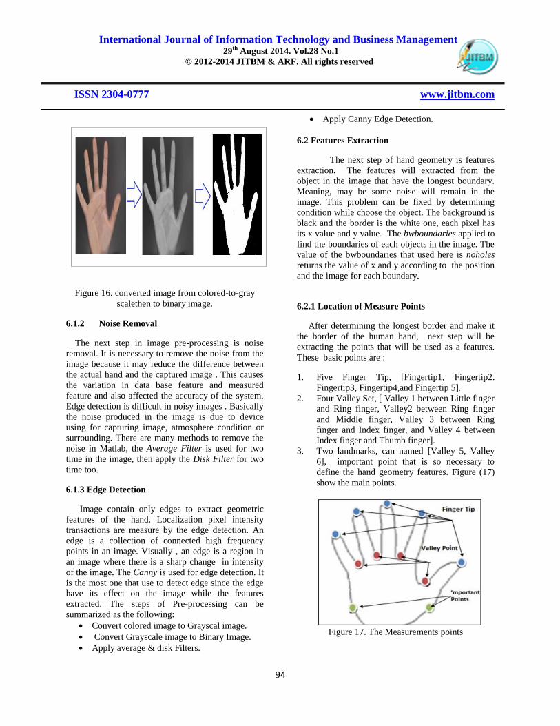
Figure 16. converted image from colored-to-gray
scalethen to binary image.
6.1.2 Noise Removal
The next step in image pre-processing is noise
removal. It is necessary to remove the noise from the
image because it may reduce the difference between
the actual hand and the captured image . This causes
the variation in data base feature and measured
feature and also affected the accuracy of the system.
Edge detection is difficult in noisy images . Basically
the noise produced in the image is due to device
using for capturing image, atmosphere condition or
surrounding. There are many methods to remove the
noise in Matlab, the Average Filter is used for two
time in the image, then apply the Disk Filter for two
time too.
6.1.3 Edge Detection
Image contain only edges to extract geometric
features of the hand. Localization pixel intensity
transactions are measure by the edge detection. An
edge is a collection of connected high frequency
points in an image. Visually , an edge is a region in
an image where there is a sharp change in intensity
of the image. The Canny is used for edge detection. It
is the most one that use to detect edge since the edge
have its effect on the image while the features
extracted. The steps of Pre-processing can be
summarized as the following:
Convert colored image to Grayscal image.
Convert Grayscale image to Binary Image.
Apply average & disk Filters.
Apply Canny Edge Detection.
6.2 Features Extraction
The next step of hand geometry is features
extraction. The features will extracted from the
object in the image that have the longest boundary.
Meaning, may be some noise will remain in the
image. This problem can be fixed by determining
condition while choose the object. The background is
black and the border is the white one, each pixel has
its x value and y value. The bwboundaries applied to
find the boundaries of each objects in the image. The
value of the bwboundaries that used here is noholes
returns the value of x and y according to the position
and the image for each boundary.
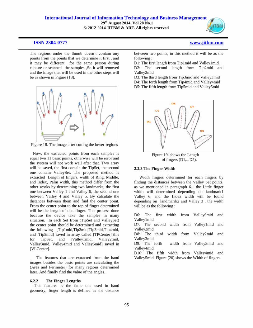
6.2.1 Location of Measure Points
After determining the longest border and make it
the border of the human hand, next step will be
extracting the points that will be used as a features.
These basic points are :
1. Five Finger Tip, [Fingertip1, Fingertip2.
Fingertip3, Fingertip4,and Fingertip 5].
2. Four Valley Set, [ Valley 1 between Little finger
and Ring finger, Valley2 between Ring finger
and Middle finger, Valley 3 between Ring
finger and Index finger, and Valley 4 between
Index finger and Thumb finger].
3. Two landmarks, can named [Valley 5, Valley
6], important point that is so necessary to
define the hand geometry features. Figure (17)
show the main points.
Figure 17. The Measurements points
International Journal of Information Technology and Business Management 29
th August 2014. Vol.28 No.1
© 2012-2014 JITBM & ARF. All rights reserved
ISSN 2304-0777 www.jitbm.com
95
The regions under the thumb doesn‟t contain any
points from the points that we determine it first , and
it may be different for the same person during
capture or scanned the samples ,So it will removed
and the image that will be used in the other steps will
be as shown in Figure (18).
Figure 18. The image after cutting the lower-regions
Now, the extracted points from each samples is
equal two 11 basic points, otherwise will be error and
the system will not work well after that. Two array
will be saved, the first contain the TipSet, the second
one contain ValleySet. The proposed method is
extracted Length of fingers, width of Ring, Middle,
and Index, Palm width, this method differ from the
other works by determining two landmarks, the first
one between Valley 1 and Valley 6, the second one
between Valley 4 and Valley 5. By calculate the
distances between them and find the center point.
From the center point to the top of finger determined
will be the length of that finger. This process done
because the device take the samples in many
situation. In each Set from (TipSet and ValleySet)
the center point should be determined and extracting
the following [Tip1mid,Tip2mid,Tip3mid,Tip4mid,
and .Tip5mid] saved in array called [TPCenter] this
for TipSet, and [Valley1mid, Valley2mid,
Valley3mid, Valley4mid and Valley5mid] saved in
[VLCenter].
The features that are extracted from the hand
images besides the basic points are calculating the
(Area and Perimeter) for many regions determined
later. And finally find the value of the angles.
6.2.2 The Finger Lengths
This features is the fame one used in hand
geometry, finger length is defined as the distance
between two points, in this method it will be as the
following :
D1: The first length from Tip1mid and Valley1mid.
D2: The second length from Tip2mid and
Valley2mid
D3: The third length from Tip3mid and Valley3mid
D4: The forth length from Tip4mid and Valley4mid
D5: The fifth length from Tip5mid and Valley5mid
Figure 19. shows the Length
of fingers (D1,...D5).
2.2.3 The Finger Width
Width fingers determined for each fingers by
finding the distances between the Valley Set points,
as we mentioned in paragraph 6.1 the Little finger
width will determined depending on landmark1
Valley 6, and the Index width will be found
depending on landmarrk2 and Valley 3 . the width
will be as the following :
D6: The first width from Valley6mid and
Valley1mid.
D7: The second width from Valley1mid and
Valley2mid.
D8: The third width from Valley2mid and
Valley3mid.
D9: The forth width from Valley3mid and
Valley4mid.
D10: The fifth width from Valley4mid and
Valley5mid. Figure (20) shows the Width of fingers.

International Journal of Information Technology and Business Management 29
th August 2014. Vol.28 No.1
© 2012-2014 JITBM & ARF. All rights reserved
ISSN 2304-0777 www.jitbm.com
96
Figure 20. Widths of fingers
6.2.4 The Palm Width
Palm width will be considered as D11.
D11: Distance from valley5 to valley6 will be
consider as the palm width, Figure (21) shows the
palm width.
Figure 21. Palm width
6.3 Other Measurements
The method based on distance‟s measurement and
angle measurement of different shapes of hand
geometry of people. The distance metric and angle
values are given below.
6.3.1 Distance Metric
D12: Distance from Valley4mid to Valley6 .
D13: Distance from Valley6 to Tip3mid.
D14: Distance from Valley4mid to Tip3mid.
D15: Distance from Valley5 to Tip3mid.
D16: Distance from Valley5 to Valley1mid .
D17: Distance from Valley5 to Valley2mid .
D18: Distance from Valley5 to Valley3mid .
D19: Distance from Valley6 to Valley2mid .
D20: Distance from Valley6 to Valley3mid .
Figure (22) shows the distances from D12 to D20.
Figure 22. Distances from D12-D20
6.3.2 Angle Values
Angle values are the line segments between
landmarks and basic points. These values can be
considered as features recognize each person. In this
method 10 angles will be calculated as the following
[45] :
Considering three lines A,B, and C, the angles will be
:
ABC = (A^2) + (B^2) – (C^2) / 2 (A)(B) ....... (14)
T = acosd (ABC). ,,,,,,,,,,,,,,,,,,,,,,,,,,,,,,,,,,,,,,,,..,,(15)
Where:
A is the first line, B is the second line, and C is the
line in front of the wanted angle, ABC and T is a
variable name, acosd is the inverse cosine degree.
In this method, the angle are defined as following:
A21: Angles between [D7 D17 D16]

International Journal of Information Technology and Business Management 29
th August 2014. Vol.28 No.1
© 2012-2014 JITBM & ARF. All rights reserved
ISSN 2304-0777 www.jitbm.com
97
A22: Angles between [D8 D17 D18]
A23: Angles between [D13 D14 D12]
A24: Angles between [D17 D19 D12]
A25: Angles between [D6 D16 D11]
A26: Angles between [D8 D18 D17]
A27: Angles between [D8 D20 D19]
A28: Angles between [D13 D15 D12]
A29: Angles between [D20 D18 D12]
A30: Angles between [D9 D12 D20]
After calculating the angles, next step will be
finding the Area and Perimeter for the same shape
that there angles calculated
6.4 The Area
The area will be calculated according to the
following equation [46] for 10 regions, and they are:
B31, B32, B33, B34, B35, B36, B37, B38, B39, and
B40.
S= 0.5 * (A+B+C) .......................................... (16)
Area =√ ( ) ( ) ( ) ........... (17)
Where:
S and Area is a variable, A, B, and C is the sides of a
triangle.
6.5 The Perimeter
The perimeter will be calculated according
to the following equation for 10 regions, and they
are: C41, C42, C43, C44, C45, C46, C47, C48, C49,
and C50.
perimeter = (A+B+C) ..................................... (18)
Where:
A, B, and C are the sides of triangle.
Now , from the first step till finding the
value of B50 will be saved by creating a database
contain all of the features that extracted, as
mentioned in paragraph 3.2 the system need ten
pictures for each person, each person have ten
samples for the right hand beside that, applying the
condition that explained before capturing the
samples.
The total features that extracted from the
dataset are : 50 for 10 person each person has 10
samples .Figure (23) show the regions that: Angles,
Area, and Perimeter will be calculated on it.
Figure 23. Angles from A21-A30
7. Training ANN & Testing
In this stage, the BPN is applied for recognize the
features that has been extracted and saved in a
database. The BPN that suggested is the most general
used, supervised learning of neural network The
BPNN that used in this method consist of :One input
layer : 50 nodes represent 50 features,One hidden
layer: 35 nodes represent one hidden layer,One
output layer: 10 nodes represent one output.
Test NN will be the next step, in this step we have
3 picture for each person to test the NN on it. If any
error occurred during testing, we can simply take
another sample. Figure (23) show the flow chart of
ANN Training & Testing..

International Journal of Information Technology and Business Management 29
th August 2014. Vol.28 No.1
© 2012-2014 JITBM & ARF. All rights reserved
ISSN 2304-0777 www.jitbm.com
98
Figure 24. Flow chart of ANN Training & Testing
8. Implementation & Result Discussion:
The BPN trained on the database, and then
tested. The recognition rate founded and the
performance goal met at 0.00001 on the epoch 12
during 07:38 time using trainlm. The population size
was 100 samples for the right hand of ten people.
During the training stage the number of neurons are
35 on the hidden layer.
The recognition rate (RR) in this method is
found according to the equation below:
RR=
* 100%
The result was 91 % , with number of
features that extracted was equal to 50 features; as
shown in table (2).
8.1 Comparison with Previous Works:
In order to make a comparisons between the
suggested method and the results adopted in this
work on the one hand, and those of the previous
works on the other hand, there are several works to
be addressed. Many researchers are addressed in this
work which got different rate and techniques for
recognition with different numbers of samples. Table
(3) show some of the previous work with the
proposed method.The RR get by using ANN with
BPN, the training parameters used in train stage with
their values are shown below in Table (4):

International Journal of Information Technology and Business Management 29
th August 2014. Vol.28 No.1
© 2012-2014 JITBM & ARF. All rights reserved
ISSN 2304-0777 www.jitbm.com
99
Table 2. Feature‟s definitions
International Journal of Information Technology and Business Management 29
th August 2014. Vol.28 No.1
© 2012-2014 JITBM & ARF. All rights reserved
ISSN 2304-0777 www.jitbm.com
100
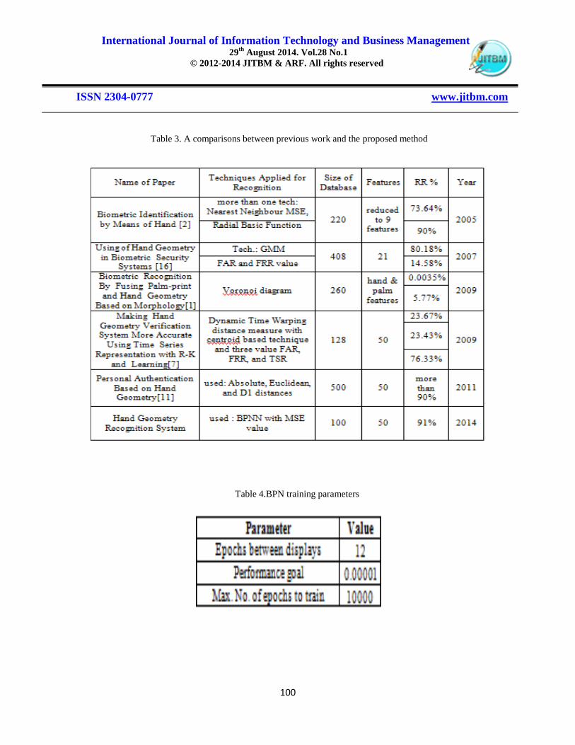
Table 3. A comparisons between previous work and the proposed method
Table 4.BPN training parameters
International Journal of Information Technology and Business Management 29
th August 2014. Vol.28 No.1
© 2012-2014 JITBM & ARF. All rights reserved
ISSN 2304-0777 www.jitbm.com
101
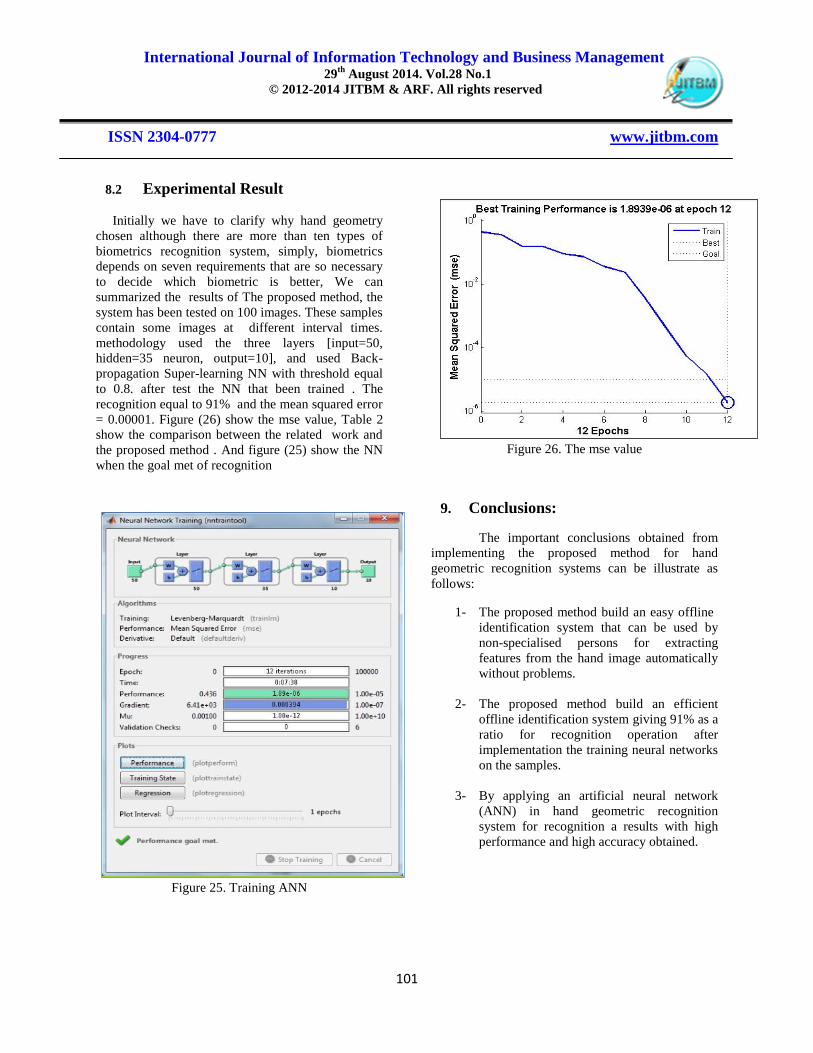
8.2 Experimental Result
Initially we have to clarify why hand geometry
chosen although there are more than ten types of
biometrics recognition system, simply, biometrics
depends on seven requirements that are so necessary
to decide which biometric is better, We can
summarized the results of The proposed method, the
system has been tested on 100 images. These samples
contain some images at different interval times.
methodology used the three layers [input=50,
hidden=35 neuron, output=10], and used Back-
propagation Super-learning NN with threshold equal
to 0.8. after test the NN that been trained . The
recognition equal to 91% and the mean squared error
= 0.00001. Figure (26) show the mse value, Table 2
show the comparison between the related work and
the proposed method . And figure (25) show the NN
when the goal met of recognition
Figure 25. Training ANN
Figure 26. The mse value
9. Conclusions:
The important conclusions obtained from
implementing the proposed method for hand
geometric recognition systems can be illustrate as
follows:
1- The proposed method build an easy offline
identification system that can be used by
non-specialised persons for extracting
features from the hand image automatically
without problems.
2- The proposed method build an efficient
offline identification system giving 91% as a
ratio for recognition operation after
implementation the training neural networks
on the samples.
3- By applying an artificial neural network
(ANN) in hand geometric recognition
system for recognition a results with high
performance and high accuracy obtained.

International Journal of Information Technology and Business Management 29
th August 2014. Vol.28 No.1
© 2012-2014 JITBM & ARF. All rights reserved
ISSN 2304-0777 www.jitbm.com
102
4- This results measured by the criteria mean
squared error (MSE) which was .0.....2
(1*10-6
) in this work.
5- In addition of the simplicity and efficiency
of the using of an artificial neural network
(ANN) in hand geometric recognition
system, the results was better than other
works that used for the same purpose, this
comparison with previous works can be
viewed with table 4.2.
10 Suggestions for Further Works:
Suggestions for further works can be
illustrated as follows:
1- Adding a new ideas to generate and extract
features from the shape of the hand to
increase the ratio for recognition operation.
2- Increasing the population size, as the ANN
can work with large database.
3- Using hand geometric recognition system in
addition with another recognition system
depends on another part of the human body.
4- Using lift hand or using the two hands for
the recognition system instead of using right
hand and compare results.
11.Reference
1. Wei C. W. , W. Shiung, “Biometric
Recognition By Fusing Palm-print and Hand
Geometry Based on Morphology”, IEEE
National Chi Nan University, 978-1- 4244-
2354, 2009 .
2. Marcos F. and Guillermo M., “Biometric
Identification by Means of Hand Geometry and
a Neural Net Classifier”, IWANN, pp. 1172-
1179, 2005.
3. Dipti R. Ch. And Ankit S., “Hand Geometry
Based Recognition System”.
4. Odgerel A., Bumduuren P., and Hiesiik K., “A
of Hand Geometry Recognition System”,
University of Seoul, Korea.
5. Lingming S., Wei W., and Fu L., “A Hand
Shape Recognition Method research based on
Gaussian Mixture Model“, International
Conference on Optoelectronics and Image
Processing, 2010 .
6. Nidhi S., Vipul S., Neelesh D., and Pragya
M., ” Hand Geometry: A New Method For
Biometric Recognition”, International Journal
of Soft
7. Computing and Engineering (IJSCE) ISSN:
2231-2307, Volume-2, Issue -6, January
2013.
8. Vit N., Chotirat A. R., “ Making Hand
Geometry Verification System More Accurate
Using Time Series Representation with R-K
Band Learning”, Bangkok 10330 Thailand,
2009.
9. Osslan O., Humberto D.,Vianey G., Leticia O.,
and Hiram M. ,”Biometric Human
Identification of Hand Geometry Features
Using Discrete Wavelet Transform”, available
at : www.Intechopen.com , 2009.
10. National Science and Technology Council
(NSTC), Subcommittee on Biometrics,
Available at www.biometrics.gov, 2006.
11. Ashesh, S. “ Design of a Hand Geometry
Based Recognition System”, Master Thesis,
Indian Institute of Technology Kanpur,
Department of Computer Science &
Engineering, 2007.
12. Zena J. “Personal Authentication Based on
Hand Geometry”, Master Thesis, College
of Computer Sceince and Mathematics,
University of Mosul, 2011.
13. GSEC, SANS Institute, “Biometric Scanning
Technologies: Finger, Facial and Retinal
Scanning”, InfoSec Reading Room, San
Francisco, Dec 2003.

International Journal of Information Technology and Business Management 29
th August 2014. Vol.28 No.1
© 2012-2014 JITBM & ARF. All rights reserved
ISSN 2304-0777 www.jitbm.com
103
14. Marios S., “Introduction to Biometric
Technologies and Applications”, ECE &
CyLab, Carnegie Mellon University. Available
at:
15. http://www.biometricscatalog.org/biometrics/bi
ometrics.
16. Arun R., ”APrototype Hand Geometry-based
Verification System”, Dept of Computer
Science and Engineering, Michigan State
University, East Lansing MI USA 4882 4.
17. Al-Ghamdi, Mohammed M., "vital data:
acoustic signature", Training College Naif
Arab University for Security Sciences, Riyadh,
2005.
18. VARCHOL P., LEVICKÝ D., “Using of Hand
Geometry in Biometric Security Systems”,
Radio engineering, Vol. 16, No. 4, pp(82-87),
2007.
19. Bansal A., Mukesh A., Sharma A., and
Anindya Gupta, “A Review Paper on
FACIAL RECOGNITION”, IJRITCC , Apr
2013.
20. Campisi P., Carter R., Crooks Ch., Govindaraju
V., Ross A., Tilton C., and Waymire D.,
“Module2 Biometric Modalities”, IEEE,
version 1.0, 2009.
21. Campisi P., Carter R., Crooks Ch., Govindaraju
V., Ross A., Tilton C. ,and Waymire D.,
“Module 2 Biometric Modalities”, IEEE,
version 2.0, 2012.
22. Biometrics Institute, Australia, available at:
23. http://www.biometricsinstitute.org
24. Jain A., and Prabhakar S., “An Introduction to
Biometric Recognition”, IEEE Transactions on
Circuits and systems for Video Technology,
Vol. 14, No. 1, pp (4-20), 2004.
25. National Biometric Security Project,“Biometric
Technology Application Manual volume One:
Biometric Basics”, 2008 .
26. GAO, “ Information Security: Challenges in
Using Biometrics”, Report number 03-1137T,
September 9, 2003. available at:
27. www.gao.gov/assets/120/110298.html.
28. Ríha Z., and Matyáš V., “Biometric
Authentication Systems”, FI MU Report
Series, Masaryk University, 2000.
29. Reid, P., “Biometrics For Network Security”,
Upper Saddle River, .J.: Prentice Hall
PTR, 2004.
30. Rhodes, Keith A., “Information Security:
Challenges in Using Biometrics”,
United States General Accounting Office.- 27 p
.
31. Boukhonine S., Krotov V. and Rupert Barry,
“Future Security Approaches and
Biometrics”, Communications of the
Association for Information Systems,
Volume 16, pp., (937- 966), 2005.
32. Ross Gary ,(2001), “Biometrics: A Self-Service
Viewpoint” Biometrics and the ATM, Advanced
Technology Group, NCR FSD, Dundee .
33. Anil K. Jain, Arun R. and Salil P., ” An
Introduction to Biometric Recognition”
Appeared in IEEE Transactions on Circuits and
Systems for Video Technology, Special
Issue on Image- and Video-Based Biometrics,
Vol. 14, No. 1, January 2004.
34. Maestre, Sandra and Nichols, Sean. “DNA
BIOMETRICS”, 12p.-available at:
danishbiometrics.files.wordpress.com/2009/08/n
st.pdf.
35. Fayza, Dusoqi A., “Bionformatics and
Information Security”, the 6th Conference on
Suadian Libraries , 2010.
36. Roberts C. , “Biometrics attack vectors and
defences”, Elsevier journal 2007.
37. Statement of Keith A Rhodes, “INFORMATION
SECURITY; challenges in Using Biometrics”,

International Journal of Information Technology and Business Management 29
th August 2014. Vol.28 No.1
© 2012-2014 JITBM & ARF. All rights reserved
ISSN 2304-0777 www.jitbm.com
104
Chief Technologist, Applied Research and
Methods, 2003.
38. Anil K Jain, Arun R., and Pankanti S., “A
Prototype Hand Geometry- Based Verification
System”, Proc. Of 2nd Int'l Conference on
Audio and Video based Biometric Person
Authentication (AVBPA), pp.,(166-171),
March, 1999.
39. SHEN W., TAN T., “Automated biometrics-
based personal identification”, proc. Natl.
Acad. Sci. USA Vol. 96, pp. 11065–11066.
September, 1999.
40. Susig, “An On-Line Handwritten Signature
Database” , Pattern Analysis and Applications,
Volume 12, Number 3, 227-236, 2009).
41. Biometrics for Network Security (Prentice Hall Series in
Computer Networking and Distributed) - page 71. Available at
http://flylib.com/books/en/4.400.1.71/1/
42. Post, ”Biometrics : Science of Identity
Management”, post on July, 2014.
Available at:
http://biometrics4u.blogspot.com/2014/07/biom
etric-recognition.
43. Sulabh K., Tanmay R., “A Novel Design for a
Palm Prints Enabled Biometric System”,
IOSR Journal of Computer Engineering,
Volume 7, Issue 3, PP 01-08 (Nov-Dec),
2012.
44. Rhee T., Neumann U., and Lewis J.P., “Human
Hand Modeling from Surface Anatomy”,
University of Southern California, Stanford
University, 2005.
45. Zhiu C., “Personal Authentication Based On
Hand Geometry Verification”, Project Of
Bachelor Of Electrical Engineering
(Mechatronics), Faculty Of Electrical
Engineering, University Technology
Malaysia. 2010.
46. Ablahad A., “A Proposed Method for
Mutational Disease Prediction Using
Bioinformatics Tools and Back-Propagation
Algorithm”, Master Thesis, University of
Zakho, 2013.
47. Srinivasa K. D., Settipalli A. R., “Hand Written
Character Recognition Using Back
Propagation Network”, Journal of Theoretical
and Applied Information Technology
(JATIT), 2005-2009.
48. Dongaree A. D., Kharde R. R., “Introduction
to Artificial Neural Network”, International
Journal of Engineering and Innovative
Technology ( IJEIT ), Volume 2, No. 1, 2012.
49. Noor A., Rafiqul Z., “Vision Based Geasture
Recognition Using Neural Networks”,
IJHCI Journal, Volume (3) : Issue (1) : 2012.
50. Wu J., and Qiu Z., “A Hierarchical Palm-print
Identification Method Using Hand Geometry
and Grayscale Distribution Features”, the 18th
International Conference on Pattern
Recognition, IEEE Computer Society,
2006.
51. Ravikanth Ch., Agrawal P., and Venkata K., “
Personal Authentication using Hand
Geometry”, Project Evalution Phase I,
Biometrics-EEL851.

International Journal of Information Technology and Business Management 29
th August 2014. Vol.28 No.1
© 2012-2014 JITBM & ARF. All rights reserved
ISSN 2304-0777 www.jitbm.com
105
12 Samples of codes

International Journal of Information Technology and Business Management 29
th August 2014. Vol.28 No.1
© 2012-2014 JITBM & ARF. All rights reserved
ISSN 2304-0777 www.jitbm.com
106

International Journal of Information Technology and Business Management 29
th August 2014. Vol.28 No.1
© 2012-2014 JITBM & ARF. All rights reserved
ISSN 2304-0777 www.jitbm.com
107

International Journal of Information Technology and Business Management 29
th August 2014. Vol.28 No.1
© 2012-2014 JITBM & ARF. All rights reserved
ISSN 2304-0777 www.jitbm.com
108
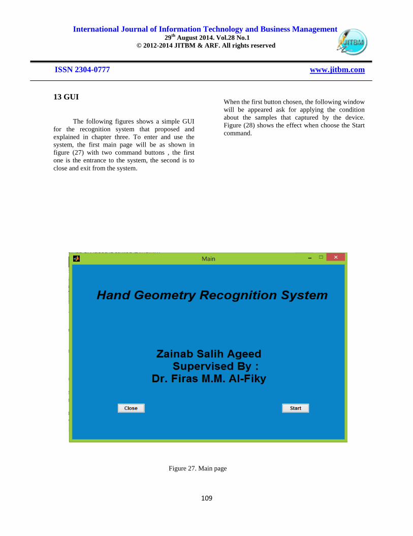
International Journal of Information Technology and Business Management 29
th August 2014. Vol.28 No.1
© 2012-2014 JITBM & ARF. All rights reserved
ISSN 2304-0777 www.jitbm.com
109
13 GUI
The following figures shows a simple GUI
for the recognition system that proposed and
explained in chapter three. To enter and use the
system, the first main page will be as shown in
figure (27) with two command buttons , the first
one is the entrance to the system, the second is to
close and exit from the system.
When the first button chosen, the following window
will be appeared ask for applying the condition
about the samples that captured by the device.
Figure (28) shows the effect when choose the Start
command.
Figure 27. Main page

International Journal of Information Technology and Business Management 29
th August 2014. Vol.28 No.1
© 2012-2014 JITBM & ARF. All rights reserved
ISSN 2304-0777 www.jitbm.com
110
As shown in figure below (28), the command
button (Login) not active, since the user should
enter a password to go to the next step of
verification person. Figure (29) show the next
window:
Figure 28. GUI of password verification
and terms in use

International Journal of Information Technology and Business Management 29
th August 2014. Vol.28 No.1
© 2012-2014 JITBM & ARF. All rights reserved
ISSN 2304-0777 www.jitbm.com
111
The window contains two command, the first one
(open image file) to select an image and the
features extracted from it then compare with values
saved in the database. Figure (30) show how the
sample selected:
Figure 29. GUI of starting window

International Journal of Information Technology and Business Management 29
th August 2014. Vol.28 No.1
© 2012-2014 JITBM & ARF. All rights reserved
ISSN 2304-0777 www.jitbm.com
112
After selecting an image, a new command will be
appear to find the tip finger‟s set. Figure (31) shows
finding the tip set.
Figure 30. GUI of selecting a sample

International Journal of Information Technology and Business Management 29
th August 2014. Vol.28 No.1
© 2012-2014 JITBM & ARF. All rights reserved
ISSN 2304-0777 www.jitbm.com
113
Then, a new command will be appear ask for
finding the valley set as appeared in figure(32):
Figure 31. GUI of finding the tip set

International Journal of Information Technology and Business Management 29
th August 2014. Vol.28 No.1
© 2012-2014 JITBM & ARF. All rights reserved
ISSN 2304-0777 www.jitbm.com
114
The final stage will decide in few seconds if the
person accepted or not by activate the command
(identification), figure (33) shows if person
accepted or not.
Figure 32. GUI of finding valley set

International Journal of Information Technology and Business Management 29
th August 2014. Vol.28 No.1
© 2012-2014 JITBM & ARF. All rights reserved
ISSN 2304-0777 www.jitbm.com
115
The second command in the starting window will
reset the system and start again, figure (34) shows if
no image selected.
Figure 33 GUI of decision stage

International Journal of Information Technology and Business Management 29
th August 2014. Vol.28 No.1
© 2012-2014 JITBM & ARF. All rights reserved
ISSN 2304-0777 www.jitbm.com
116
Figure 34. GUI when no image selected
International Journal of Information Technology and Business Management 29
th August 2014. Vol.28 No.1
© 2012-2014 JITBM & ARF. All rights reserved
ISSN 2304-0777 www.jitbm.com
117
Dr. Firas Mahmood Al-Fiky,
received his BSc, MSc and
PhD degrees from University
of Mosul-Iraq, College of
Engineering, Electric dept. at
1997, 2000 and 2007
respectively. He has a PhD in
Computer Engineering, he is
lecturer since 2007. He started teaching and
supervising post graduate courses since 2009 and
until now. He is a director of IT and Networks center
in Duhok Polytechnic University (DPU).
Zainab Salih Ageed, received her
BSc at 2009 in computer science and
mathematics Dept. at Mosul
University. She is working now to
get MSc degree in computer science.
This paper is one of her research part
productions working together with her supervisor
Dr. Firas M. Al-Fiky.

International Journal of Information Technology and Business Management 29
th August 2014. Vol.28 No.1
© 2012-2014 JITBM & ARF. All rights reserved
ISSN 2304-0777 www.jitbm.com
118

International Journal of Information Technology and Business Management 29
th August 2014. Vol.28 No.1
© 2012-2014 JITBM & ARF. All rights reserved
ISSN 2304-0777 www.jitbm.com
119