australia and new zealand bim best practice guidelines
TRANSCRIPT

AUSTRALIA AND NEW ZEALAND BIM BEST PRACTICE GUIDELINES

DISCLAIMER
These guidelines are provided for general educational and informational purposes only. They are intended to provide accurate summary information pertaining to the subject matter of the guidelines but within the limitations of the size of the guidelines. They are not intended to be a definitive guide nor to amount to specific advice in respect of any particular project. You must obtain professional or specialist advice before taking, or refraining from, any action on the basis of these guidelines. The Australian Institute of Quantity Surveyors Ltd (AIQS) and the New Zealand Institute of Quantity Surveyors (Inc) (NZIQS) make no representations, warranties or guarantees, whether express or implied, that the content of these guidelines is complete or up to date. AIQS and NZIQS and its authors and editors fully exclude any liability by any or all of them in any way to any person or entity for damages in respect of or arising out of any reliance, in part or full, by such person or entity or by any other person or entity, upon any of the contents of these guidelines for any purpose.
COPYRIGHT
All rights reserved. No part of these guidelines may be adapted, modified, reproduced, copied, or transmitted, in any form or by any means, whether electronic, mechanical, photocopying, recording or otherwise, except in accordance with the provisions of the New Zealand Copyright Act 1994 and the Australian Copyright Act 1968, without the prior written permission of the AIQS and NZIQS. Furthermore, these guidelines shall not be stored in whole, part, adapted, or modified form, in or for any retrieval system of any nature without the prior written permission of the AIQS and NZIQS.
© Australian Institute of Quantity Surveyors Ltd and New Zealand Institute of Quantity Surveyors, Inc (2018)
Australian Institute of Quantity Surveyors Ltd: - www.aiqs.com.auNew Zealand Institute of Quantity Surveyors Inc. – www.nziqs.co.nz

CONTENTS
i Foreword 5
ii Introduction 6
1 BIM For The Quantity Surveyor 8
1.1 The BIM Process 8
1.2 4D 8
1.3 5D 9
2 What To Expect On A BIM Project 10
2.1 BIM As A Contract Deliverable 10
2.2 Non-Contracted BIM 10
3 Collaboration 11
4 Quantity Surveyor’s Role In The BIM Execution Plan 12
4.1 The BIM Execution Plan (BEP) 12
4.2 The Quantity Surveyor 12
5 Information To Be Provided In The Model 14
5.1 Model Content Plans (MCP) 14
5.2 Levels Of Development (LODs) In The BIM Development Process 14
5.3 Common BIM Exchange File Types 14
6 Model Integration And Validation 16
6.1 BIM Quality Assurance and Quality Control (BIM QA/QC) 16
6.2 Benefits to Quantity Surveyor 16
6.3 Quantity Surveyor BIM Competencies 16
6.4 Checking Design Documents for Quantity Take-Off (QTO) 16
7 Legal 19
7.1 Legal Considerations for use of BIM 19
Appendix A BIM Definitions 20
Appendix B Key Modelling principles 22
Appendix C BIM Execution Plan 44
Project Information 44
Project Schedule 44
Key Project Contacts 44

4 AUSTRALIA AND NEW ZEALAND BIM BEST PRACTICE GUIDELINES
QS and BIM 45
Introduction 45
Software & File Format 45
Modelling Requirements 45
Key Object Parameters & Units of Measure (UOM) 46
Model Content Plan 46
QS Responsibilities 46
Appendix D – NZ BIM Handbook – Appendix C Levels of Development definitions 47
1 General 47
2 Level of Development versus Level of Detail 47
3 LOD Notations 47
4 Aspects of LOD 48
5 LODDefinitions 48
Acknowledgements 50

5AUSTRALIA AND NEW ZEALAND BIM BEST PRACTICE GUIDELINES
i FOREWORD
Building Information Modelling (BIM) has become more popular in recent years as digital construction technology is beginning to fundamentally transform the building and construction industry practice in the delivery of the built environment. New technologies will improve construction productivity as well as the level of integration and collaboration across the various disciplines in the construction value chain. It is therefore important for the industry to embrace the technology with clarity.
These guidelines highlight key knowledge areas relating to BIM, including information on what quantity surveyors need to know about BIM, specifics about 5D BIM (what it actually is and what it isn’t), what to expect in a BIM project, timeline of a quantity surveyor’s role in the BIM Execution Plan, what information quantity surveyors need from 3D digital models, quality assurance, and legal issues to be aware of whilst working on BIM projects.
This document is an essential guide for quantity surveyors, cost managers or cost estimators looking to be involved with a project utilising BIM. Throughout the document, the term quantity surveyor (QS) will be used in reference to all the above-mentioned roles.

6 AUSTRALIA AND NEW ZEALAND BIM BEST PRACTICE GUIDELINES
ii INTRODUCTION
What is the purpose of this document?This Best Practice Guideline is aimed at promoting the adoption of BIM amongst quantity surveyors at all levels and capabilities in Australia and New Zealand, with a view to support future development and enhance the value of quantity surveyors to the property and construction industry.
A common BIM language has been adopted to facilitate a consistent and uniform approach to BIM across Australia and New Zealand.
What is BIM?BIM supports more effective management of information through the lifecycle of a project, from initial design to construction, operations, and finally decommissioning. BIM is a tool that facilitates greater collaboration between engineers, owners, architects, quantity surveyors, and contractors in a virtual environment (common data environment), enabling efficient sharing of information across these disciplines.
Fundamentally, BIM is a process that leverages technology to facilitate collaboration amongst all parties during the project lifecycle. BIM is not software, nor is it solely a 3D model. BIM can be used, in various forms, on all sizes and types of projects.
Why is BIM important to the Quantity Surveyor?BIM is an effective digital tool for the quantity surveyor to assess and affect the design and delivery process for better commercial outcomes.
For the quantity surveyor, it is essential to understand the importance of their involvement from the outset of a project, communicating with the design team effectively whilst simultaneously guiding and understanding their approach, in order
to interrogate and review a model throughout the project’s lifecycle.
By adopting best practice, we aim to:
• reduce cost and increase efficiency
• provide certain and consistent outcomes
• establish a base skill level for upskilling and education
• provide an industry-specific pool of common knowledge
• allow other stakeholders to understand the specific outcomes we require
• provide a basis and starting point for future development
• set the minimum level of compliance for ethics and legal implications.
The adoption of best practice also serves as a tool to maintain quality and consistency in the absence of mandatory standards and legislation, especially in the BIM space which is still very much in its infancy in Australia and New Zealand.
Role of the AIQS and NZIQS BIM CommitteesThis BIM Best Practice Guideline has been developed through a collaboration between the AIQS and NZIQS BIM Committees.
The Australia and New Zealand Institutes of Quantity Surveyors BIM Best Practice Guidelines are intended to encourage and support increased adoption of BIM by quantity surveyors in the Australian and New Zealand construction industries.

7AUSTRALIA AND NEW ZEALAND BIM BEST PRACTICE GUIDELINES
Acknowledgments Both the AIQS and NZIQS acknowledge the significant contribution of their respective BIM Committees in bringing this Best Practice Guideline to fruition. This Best Practice Guideline utilises material produced by a number of parties. Both the AIQS and NZIQS thank NATSPEC Construction Information for allowing the adoption and adaptation of main definitions (Appendix A), and the New Zealand BIM Acceleration Committee for allowing the inclusion of “Appendix C” (Level of Development definitions) of the NZ BIM Handbook (November 2016).
NZIQS BIM CommitteeKeeley Pomeroy, Tjaart Grové, Jasper Mbachu, Tom Chatterton, Chris Prigg, Tony Shaw, Derek Thurnell, Phil Molineux, Stephen Kleehammer, and Kris Morrison.
AIQS BIM CommitteeAndrew Brady, Peter Clack, Steve Appleby, Lukman Dereinda, Paul Roberts, Nathan Trevaskis, Alan Graef, Matt Hemming, and Grant Warner.

8 AUSTRALIA AND NEW ZEALAND BIM BEST PRACTICE GUIDELINES
1 BIM FOR THE QUANTITY SURVEYOR
1.1 The BIM ProcessBIM1 is an agreed collaboration process that commonly ends with a 3D design linked to a database. BIM is essentially the same as 2D documentation; drawings, specifications etc, however it is easier to visualise.
The process is requested in the Employer’s Information Requirements (EIR) then defined in the project BIM Execution Plan which is developed at the start of the project by the project team, including the client. This process may be facilitated by a BIM Manager but requires input from all parties. It is essential that the quantity surveyor articulates what information they need and collaborates with the design team to agree what will and what will not be included within the model.
Among other common uses, BIM extends 3D design with the ability to add a time dimension (4D) and a cost dimension (5D).
The fifth dimension (5D) in BIM is a misnomer – it doesn’t exist in physics. It commonly refers to the addition of cost within specific elements within the model which in reality, does not happen.
Now that BIM authoring software is mainstream there are common misconceptions regarding the role of the quantity surveyor, which include:
• a Bill of Quantities can be produced with the click of a button
• all quantities reside within the model
• an architect or engineer can extract quantities from a model, so they can now do the role of the quantity surveyor.
This document allays these misconceptions and provides guidance on what can be achieved through the utilisation of BIM-based processes.
While a quantity surveyor may use a BIM to speed up some basic quantity take-off, the true value of
the quantity surveyor is not in counting doors or furniture, rather in the interrogation of the design intent or trade contractor models to understand what isn’t included. This enables the quantity surveyor to recommend alternatives which could be adopted, and ultimately provide the client with assurance that the most cost-effective option has been put forward.
Quantity surveyors using BIM undertake the same fundamental process as traditional quantity surveying; they just have increased time to spend on value-adding processes, including benchmarking cost rates and simulating the effects changes to, material types or methods of construction could have on the overall project budget. The deliverables for design phase, pre-contract and post contract quantity surveying are the same but enhanced by the collaboration process that BIM enables and the ability to use digital information for quantification. To a quantity surveyor using BIM, greater emphasis is placed on the verification and validation process.
BIM collaboration is a key component in the quantity surveyor’s tool bag – one that greatly enhances the value they bring to the client.
1 Refer to NATSPEC National BIM Guide & New Zealand BIM Handbook Second Edition for more detail

9AUSTRALIA AND NEW ZEALAND BIM BEST PRACTICE GUIDELINES
1.2 4DThe fourth dimension (4D) refers to the linking of the 3D design models with the program schedule.
The quantity surveyor can play a role as he would in a traditional project, by working with the planner and providing commercial advice on, for example, labour and plant hire. Together they can develop a lean process that optimises resources.
Cost escalation on projects from delay, often occurs through lack of planning of activities – what trades are going to which jobs, in which areas, and at which times to maximise the site’s constraints. 4D allows for these activities to be simulated and tested multiple times virtually, where the cost of getting it wrong during the simulation is a tiny fraction of having an unproductive site.
1.3 5D 5D is about cost, not quantities. Extracting quantities is not 5D nor is it quantity surveying. It is in this phase or space that the quantity surveyor utilises their skill set and knowledge to perform a professional cost management role on the project.
Finland’s COBIM 2012, Series 7, (Page 5) states; “a BIM does not resolve quantity take-off related issues “exhaustively” and not all quantities needed during a project can be taken off from a BIM. The professional skill of a quantity surveyor is still needed for assessing the validity of the source data and source materials, ensuring the coverage of the take-off, proposing alternative solutions and analysing the results.”
Leveraging the 3D information model, quantity surveyors can achieve the following:
• fast and efficient quantity validation and verification
• rapid processing of design revisions/updates
• more reliable and responsive cost advice/cost estimation
• quickly cost design options to allow early informed decisions.

10 AUSTRALIA AND NEW ZEALAND BIM BEST PRACTICE GUIDELINES
2 WHAT TO EXPECT ON A BIM PROJECT
Sometimes BIM will be included in a contract; sometimes it won’t. In both cases, one can expect BIM to be used by the design/construction teams. The role of the quantity surveyor is to form a dialogue with these teams to guide the ways the models are developed to get improved value.
Although there are many types of procurement methods employed to deliver a project, there are two key forms of BIM projects, each with their own advantages and disadvantages to the quantity surveyor:
1 BIM as a contract deliverable; and
2 BIM used outside of any contract deliverable.
2.1 BIM as a Contract Deliverable
When BIM is a contract deliverable, the quantity surveyor will be expected to play their part. The client will have significant input to the digital process and will have contract clauses and deliverables for the design, project controls, and main contractor parties. Procurement of consultants and construction contractors is a key part of this process, with often non-priced “best for project” weightings for project team selection. The client is required to set the BIM brief for the project team to respond to in a BIM Execution or Management Plan (BEP or BMP). The project is typically set up to ensure that the data created throughout the design and construction phases is suitable for asset operation.
The quantity surveyor’s input early in the process is imperative to ensure the model is set-up with proper geometry and contains key information for effective cost planning is addressed in the project BEP. This process enables the quantity surveyor to manage BIM expectations efficiently.
2.2 Non-Contracted BIMProjects where BIM is not a contract deliverable are common and the models if shared with the quantity surveyor still provide value for cost planning activities.
Typically, some models are exchanged during this process organically (e.g. for design coordination, construction planning and programming, and the handover of a structural model for steel shop detailing). Quantity surveyors will have to request the design team to export models in a format that their software can read. The models may or may not be optimal for cost planning or tendering quantity extraction due to the non-binding nature of the relationship of the initiation of the project.

11AUSTRALIA AND NEW ZEALAND BIM BEST PRACTICE GUIDELINES
3 COLLABORATION
As quantity surveyors, communication is needed with the design team, so they know what information is required, (including unit of measurement etc.) from the digital model at each stage of the project to facilitate efficient cost planning. This is typically done via a set of standard protocols and templates, included in documents such as the BEP, which are developed at the outset of the project.
Established collaboration practices in the construction industry are document-centric, however, significant improvement in recent years has allowed models to be easily shared and viewed by the project team.
The keys to a collaborative BIM project for the quantity surveyor are:
• early communication of the client’s BIM requirements with the design team
• agreed set of requirements established prior to the design commencing, set out in a BIM Execution Plan / BIM Management Plan, and supported by a BIM Model Content Plan
• respect and appreciation of other’s disciplines and their objectives
• appropriate collaborative software in place; and
• an individual/organisation in place coordinating and managing the BIM process.
Design team members can be reluctant to provide their models to quantity surveyors and contractors, often citing liability or Intellectual Property concerns. While these concerns may be valid, discussing what the model will be used for and how it will be used at specific stages, will often result in designers being more open to providing their models.
In summary, the quantity surveyor needs to articulate their requirements to the design team, ensure this is recorded within the BEP and work with the designers to ensure they understand what information is used and how it will be relied upon by the quantity surveyor. This also enables the design team to communicate what information is not going to be modelled, ensuring clarity of approach by all parties.

12 AUSTRALIA AND NEW ZEALAND BIM BEST PRACTICE GUIDELINES
4 QUANTITY SURVEYOR’S ROLE IN THE BIM EXECUTION PLAN
4.1 The BIM Execution Plan (BEP)
To effectively introduce BIM into the project, it is important for the project team to agree on how they plan on collaborating, when this will happen and what will be developed and shared. The BEP outlines the details of this.
A BEP helps the client and project team members document the agreed deliverables. It is common for the client to issue their own BEP template as part of the tender process and assess the tenderers based on their responses.
The BEP is usually developed at the start of the project and when new project members have been appointed to accommodate their participation.
By developing a BEP, the employer and project members can:
• clearly understand the strategic goals for implementing BIM on the project
• understand their roles and responsibilities for model creation, maintenance and collaboration at different stages of the project
• design a suitable process for them to participate in the implementation
• outline additional resources and services that may be needed; and
• provide a baseline to measure progress throughout the project.
The content of a BIM Execution Plan includes the following:
• project information
• defined BIM goal and uses
• each project member’s roles, staffing, and competencies
• BIM process and strategy
• BIM exchange protocol and submittal format
• BIM data requirements
• collaboration procedures and method to handle shared models
• quality control; and
• technology infrastructure and software.
The BEP can be appended with additional information to facilitate additional members joining the project at later stages. Updates to the BEP should be made with the permission of the employer or their appointed BIM Manager and should not go against conditions of the Principal Agreement.
A copy of an example BEP is attached at Appendix C of this document.

13AUSTRALIA AND NEW ZEALAND BIM BEST PRACTICE GUIDELINES
4.2 The Quantity Surveyor The quantification and pricing of the project using BIM is the quantity surveyor’s specialist area. It provides the coupling point through which the quantity surveyor’s cost advice and cost management roles dovetail into the wider roles of other key players in the BIM space, from conception to disposal of the building or infrastructure asset. In addition to being involved in a collaborative working relationship with other role players, the quantity surveyor’s key role in the BIM environment is the provision of cost-related inputs that could enrich the reliability and utility of the BIM modelling process and the associated building information integration and management.
The quantity surveyor also helps to critique the comprehensiveness of the digital information of the 3D BIM model for accuracy and reliability of use for cost advice or cost management. The quantity surveyor’s required Level of Development from the digital data (whether graphical or non-graphical) depends on the expected quality output of the quantity surveyor’s cost information and the agreed Level of Development expected of the 3D information model at the specific stage of design development.
The quantity surveyor’s cost-centred inputs are required at the pre-contract, post-contract and operation stages of the BIM Execution Plan.
The following list, while not exhaustive, are some key points for a quantity surveyor to be mindful of, and where appropriate, provide input when involved with a project that has a BEP:
• engage with the author of the BEP to enable a common understanding and provide input where appropriate
• understand expectations and timing of deliverables
• understand frequency and types of files that will be issued
• understand the extent of model validation being performed before issue
• understand how information is being shared, updated, amended, etc
• understand the proposed classification coding system and how this could be leveraged by the quantity surveyor; and
• communicate / elaborate not only for the use of quantity surveyors but also other downstream users that:
• generic model objects should not be used for any elements that are required to be quantified
• digital models should be modelled the way the project is physically to be built; and
• other key modelling principles from a quantity surveyor’s perspective can be seen in Appendix B.

14 AUSTRALIA AND NEW ZEALAND BIM BEST PRACTICE GUIDELINES
5 INFORMATION TO BE PROVIDED IN THE MODEL
A BIM contains graphical (2D/3D objects) and non-graphical (object data) information that can be extracted for quantification. The designer needs to create, place and export their models in a way that enables this information to be used for quantification purposes.
Model content will need to be able to be measured in accordance with a standard method of measurement. There is a balance between the designer’s model work in progress, the design milestone deliverable, and the content within the BIM environment. Typically, the model’s content will be described in the BIM Execution Plan, and a Model Content Plan.
5.1 Model Content Plans (MCP)A Model Content Plan (MCP) is a communication tool just like the BEP and is often appended to the BEP. It is used to describe the minimum object content that will reside in the BIM for cost plan and estimate use. It is a spreadsheet template which lists the typical AIQS and NZIQS building elements plus the required model content based on a standard method of element measurement and/or classification system. This enables the quantity surveyor to undertake model-based quantification from BIM for costing purposes. The MCP is not used to dictate how a design authoring software structures data.
By using the MCP and the BIM together the quantity surveyor can determine what should have been modelled, the unit type (count, length, area, and volume) and at which stage of the BIM’s development those elements should exist in the BIM(s).
The MCP can be a contractual document if required however it should not be a burden for the design team. Just like the BEP, it aims to communicate the standard of minimum attributes/parameters, which enable measurement of the objects for the quantity surveyor’s use. For example, a quantity surveyor measures the surface area of ceilings, walls, floors, and roofs. This value [area m2] is a standard attribute/parameter within BIM authoring software. Therefore, no additional effort is required from the designer but to model these elements correctly and categorise them as per the Model Content Plan.
1 From the NZ BIM Handbook, 2nd Edition, Nov. 2016, Appendix C) https://www.biminnz.co.nz/bim-tools/

15AUSTRALIA AND NEW ZEALAND BIM BEST PRACTICE GUIDELINES
5.2 Levels of Development (LODs) in the BIM development process
The Level of Development (LOD) is a widely-debated subject and something the quantity surveyor will need to understand in more detail. LOD refers to a scale that is used to show the reliability of content that is included for specific model elements at different times during model development. The main purpose of Levels of Development, when incorporated into the BEP, is to give clarity to each member of the project team as to what they are required to author in their models at each stage, and to what extent others can rely on them. It is important to note that LOD’s apply to individual elements within a model, not the overall model. For more information, please read NZ BIM Handbook, November 20161.
A copy of Appendix C of the NZ BIM Handbook is in Appendix D of this document.
5.3 CommonBIMexchangefiletypes
There are many BIM authoring software packages in use which produce their own proprietary native file type. Various interoperable file types exist which can be read by differing estimating and quantity surveying packages thereby enabling data from BIM files to be leveraged whatever the originating design software.
A quantity surveyor should review their own chosen software to determine which file formats they will require to best leverage off the model. The extent of information that can be leveraged varies depending on the quantity surveyor’s software and the design authoring software. It is highly recommended that the quantity surveyor engages with their software vendor for guidance and understanding of what is required.

16 AUSTRALIA AND NEW ZEALAND BIM BEST PRACTICE GUIDELINES
6 MODEL INTEGRATION AND VALIDATION
6.1 BIM Quality Assurance and Quality Control (BIM QA/QC)
Quality Assurance and Quality Control (QA/QC) for BIM is about the analysis and reporting of 3D models to check the integrity, quality and coordination level of the designs. While BIM software and technology offers easy visualisation along with virtual walk-through functionality, robust QA/QC should highlight potential flaws, ambiguities, omissions, etc., of design intent or design documentation.
This is an additional step that compliments the quantity surveyor’s traditional QA process and is not unlike that of the 2D process. Additionally, it facilitates clash detection of components / elements and ensures the 3D model conforms to the BIM Execution Plan, design and construction codes and standards, alongside industry and business best practices.
6.2 BenefitstoQuantitySurveyor
BIM QA/QC is essential to release the main benefits, which are:
• increased visualisation of the building
• bulk checking device for manual measurement
• efficient data extraction for estimating at various design stages, as well as leveraging off the model and producing schedules of quantities
• more efficient identification and costing of design changes; and
• cost estimates can be derived, and facility management software can then also analyse the material lifecycle and maintenance considerations of the building.
The main risks with the quantity surveyor BIM process are:
• misleading model content including geometry and incomplete data which leads to incorrect data extraction
• that digital models / BIM don’t contain all the quantities needed for quantity surveyor’s and therefore the role of the quantity surveyor is to use their specialist knowledge to access the validity of the data and supplement where required
• model content not meeting design phase expectations; e.g. Construction Industry Council (NZ) Guidelines, Building Code, BIM Levels of Detail / Level of Information, Project BIM Execution Plan
• lack of access to the Common Data Environment (CDE)
• 3D model vs. 2D plans vs. specifications, including precedence of these documents
• BIM experience, software limitations and technical ability from the quantity surveyor; and
• Work in Progress including objects yet to be modelled.
Mitigation of risks include:
• BIM Execution Plans
• proactive communication
• BIM protocol
• Model Content Plans
• ownership of objects
• understanding when objects will appear in the design; and
• rules for removing duplication of objects and elements.

17AUSTRALIA AND NEW ZEALAND BIM BEST PRACTICE GUIDELINES
6.3 Quantity Surveyor BIM Competencies
For quantity surveyors to operate in the BIM environment, skills and competence in BIM are required. Company investment in BIM is both essential and advantageous for quantity surveying consultancies, as well as contractor and subcontractor estimators and quantity surveyors due to the commercial benefit which BIM provides. Examples of BIM skill competencies for a quantity surveyor include:
• understanding design modelling process and development
• identifying quantities for the appropriate estimating level (e.g. room boundary, AIQS and NZIQS Elements to objects)
• manipulating models to acquire quantities usable for estimation
• interrogating and validating the extent and reliability of the digital model and its information content
• ability to adjust a cost plan to suit data available in the model over the duration of evolving design phases
• ability to operate in the Common Data Environment (CDE)
• identify placeholders or model issues; and
• a systematic, methodical approach to follow or establish procedures.
As a baseline, quantity surveyors need to understand how to interpret BIM Execution Plans, prepare their own BIM Execution Plans, and report unsuitable/unusable data before co-ordination and drawing production for milestone hold points.
Consideration should be given to empower or nominate an office champion/s or BIM Managers to lead and educate other colleagues and represent the company on projects.
6.4 Checking Design Documents for Quantity Take-Off (QTO)
The quantity surveyor retains ownership of the quantities and has always been the backup professional to check design documents during early design phases, through to preparing tender documentation, in-particular when providing estimates and/or schedules of quantities. The quantity surveyor needs to understand how to assess a BIM as being fit for use for Quantity Take-Off (QTO), estimation or tendering. This involves assessing and understanding model information.
To resolve any issues during the QTO quality assurance process, these are best initiated via verbal conversations and workshops with the various design disciplines.
Conversations should address:
• clarification of expectations from various project stakeholders
• contractual BIM
• Levels of Development specification
• design stages and programme
• data integrity and reliability, including:
• communicating the impacts of poor object information
• showing designers how object data is used in the Quantity Take-Off
• using an example from the designer’s own projects or team members
• agreeing on the best data approach for all parties especially for the ultimate end user
• quantity surveyor specific coding - design effort vs payback
• file format: IFC vs DWFx; and
• access to the CDE and project data, including Work in Progress (WIP).

18 AUSTRALIA AND NEW ZEALAND BIM BEST PRACTICE GUIDELINES
Following the conversation with BIM team members, a formal query sheet (Request for Information or RFI) should be raised to communicate and resolve issues.
Model interrogation and validation for QTO involves:
• Visual inspections – check for rogue objects, contradictions, clashes, gaps, etc
• inspecting schedules and non-graphical data
• use of 3rd party model checking software
• checking for what is not modelled.
Sense/sanity checks should include:
• Foot print + Upper Floors & GFA/FECA
• external face area
• category contents and the data within each family; and
• gap analysis.

19AUSTRALIA AND NEW ZEALAND BIM BEST PRACTICE GUIDELINES
7 LEGAL
7.1 Legal Considerations for use of BIM
On projects that use BIM-based digital technologies, there are legal considerations which should be addressed early in the contract formation phase.
There should be an agreed protocol defining the ways in which BIM will be implemented in the project and the limits of that implementation. The agreed protocol should be incorporated by reference into the contract documentation.
The BIM, at the agreed Levels of Development, should ideally form part of the construction contract documentation and in the contract terms for each professional appointment, including the quantity surveyor.
Other amendments to the legal documentation may be needed depending on the BIM Levels of Development that are being used in the project. These include:
• clarity as to assumption of risk and liability in relation to the BIM, including:
• the duties, rights, and responsibilities of the BIM Manager
• which parties are liable for mistakes in the BIM and to which other parties do they owe liability
• the lines of communication between the BIM Manager and the various construction and consultant parties
• time limitation periods applied in relation to each party’s liability for information included the BIM
• level of duty of care imposed on the consultants, including the quantity surveyor, with regard to use of the BIM. Level of accuracy required in the BIM
• are the existing insurance provisions appropriate for a BIM project?
• do existing contract terms reflect the way in which services will be performed in a BIM project?
• do existing copyright licenses incorporated in contract terms with the various consultants require amendment? For example, does existing wording limit the quantity surveyor’s right to rely on the BIM and or the building owner’s right to use the BIM throughout the life of the building?
• extent that third parties, such as future building owners and future building users, are entitled to use and rely on the BIM and output data
• who owns the copyright in the BIM as a whole?
• who owns the data that goes into the BIM?
• who owns the outputs from the BIM, such as cost data produced by the quantity surveyor?
• how will commercially sensitive data be dealt with in the BIM, so that it cannot be accessed by everyone?

20 AUSTRALIA AND NEW ZEALAND BIM BEST PRACTICE GUIDELINES
Appendix ABIMDefinitions
4D Leveraging a 3D model linked to time or scheduling data. Model objects and elements with this data attached can be used for construction scheduling analysis and management.
5D Leveraging a 3D Model linked to cost data.
6D Not yet established as an industry-accepted singular definition. The 6th definition is typically the use of BIM to support either sustainability or operations-centric activity. Rather than considering either of these as a ‘dimension’, better to make reference to specific Model Uses, such as Operations Planning.
Asset information modelling (AIM)
A sub-type of Information Models supporting the maintenance, management, and operation of an asset throughout its lifecycle. An Asset Information Model (AIM) is used (a) as a repository for all information about the asset; (b) as a means to access/link to enterprise systems (e.g. CMMS and BMS); and (c) as a means to receive and centralise information from other parties throughout project stages.
Asset Information Requirements (AIR)
The data or information requirements related to an Asset. Asset Information Requirements (AIR) are typically fed into the Asset Information Model and form part of the Employer’s Information Requirements.
BIM Execution Plan (BEP) A formal document that defines how a project will be executed, monitored and controlled with regard to BIM. A BEP is developed at project initiation to provide a master information/data management plan and to agree on roles and responsibilities for model creation and data integration throughout the project.
The BIM Execution Plan is developed by suppliers – typically pre-contract to address the Employer’s Information Requirements (EIR).
BIM Management Plan (BMP) Same as BIM Execution Plan.
BIM Manager Leads and coordinates the BIM processes for the project.
Common Data Environment (CDE)
A single source of information which collects, manages and disseminates relevant, approved project documents for multidisciplinary teams in a managed process. A Common Data Environment (CDE) is typically served by a Document Management System that facilitates the sharing of data/information among Project Participants. Information within a CDE needs to carry one of four labels (or reside within one of four areas): Work In Progress Area, Shared Area, Published Area, and Archive Area.
Construction BIM Execution Plan A BIM Execution Plan for the construction phase of a project.
Construction Operations Building Information Exchange (COBie)
COBie (Construction Operations Building Information Exchange) is a specification for the capture and delivery of design/ construction information to Facility Managers. COBie Specifications can be collated using a spreadsheet template or a COBie-enabled software solution.

21AUSTRALIA AND NEW ZEALAND BIM BEST PRACTICE GUIDELINES
Design BIM Execution Plan A BIM Execution Plan for the design phase of a project.
Federated Model A BIM Model which links (does not merge) several Mono-Discipline Models together. As opposed to Integrated Models, Federated Models do not merge the properties of individual models into a single database.
Geographic Information System (GIS)
A system that integrates hardware, software, and data for capturing, managing, analysing and displaying all forms of geographically referenced information.
Globally Unique Identifier (GUID) A unique code identifying each object/space.
Industry Foundation Class (IFC) IFC refers to a neutral/open specification (schema) and a non-proprietary ‘BIM file format’ developed by BuildingSMART®. Major BIM Software Tools support the import and export of IFC files (also refer to ISO 16739).
Interoperability The ability to exchange Information without data loss and without a special effort. Interoperability may refer to systems, processes, file formats, etc. Interoperability is not synonymous with openness. For example, interoperable file formats can be proprietary-closed (e.g. RVT), proprietary-open (e.g. DWF) and non-proprietary (e.g. IFC).
Metadata Commonly defined as “data about data”, this differs from the data itself.
Model Element Authoring Schedule (MEA)
Assigns responsibilities to Model Elements via an Author and defines the Level of Development of model elements aligned to project phases.
Project BIM Brief A document developed by a client to outline their BIM requirements when engaging designers or design and build teams.
Can also be referred to as Employers Information Requirements (EIR).
Quantity Surveyor Includes, but is not limited to the designations:
• Building or Construction Cost Consultant, Cost Manager, Cost Planner, Cost Engineer, Cost controller, Economist or Value Manager
• Estimator, contract administrator
• Project Manager, Superintendent or Independent Certifier
and similar work dealing with any aspects of construction costs and cost planning and means a person qualified under conditions laid down by the Institute from time to time and includes any teacher, lecturer, professor or student involved in such work.

22 AUSTRALIA AND NEW ZEALAND BIM BEST PRACTICE GUIDELINES
Appendix B Key Modelling principles
IntroductionThe Purpose of this document is to outline key principles quantity surveyors should be aware of and wish to make industry aware of.
This document establishes best practice in modelling and encourages the quantity surveyor to leverage off the digital documentation.
Rule Principles:ELEMENT OF MODELLocation 1.0Setup 2.0Placement 3.0Geometry 4.0Data (non-graphical) 5.0Procedures 6.0
• The rule has to be generic and cut through a broad base of development/ projects
• The principle should be easily applied on a small project and easy enough to expand on more complex projects
• Should be software agnostic
• Promote collaboration with other disciplines by keeping key criteria to a minimum
• Uses known national standards (e.g. NPWC Elements, etc.).

23AUSTRALIA AND NEW ZEALAND BIM BEST PRACTICE GUIDELINES
1.0
LOCA
TIO
NM
odel
ling
Item
Corre
ct m
odel
bas
e po
int &
surv
ey p
oint
(AHD
/ N
ZVD
& A
ngle
to T
rue
Nor
th)
Mod
ellin
g Pr
inci
ple
To e
nsur
e al
l des
ign
mod
els c
an b
e ea
sily
and
read
ily c
ross
-exa
min
ed, d
esig
n te
ams s
hall
refe
renc
e ex
act
sam
e co
ordi
nate
s for
X, Y
, Z, b
ase
poin
t, su
rvey
poi
nt, A
ustra
lian
Heig
ht D
atum
/ N
ew Z
eala
nd V
ertic
al
Datu
m a
nd A
ngle
to T
rue
Nor
th.
Mod
ellin
g Pr
inci
ple
Exam
ple
Mod
el se
t out
poi
nt a
nd o
rient
atio
n to
be
nom
inat
ed in
the
BIM
Exe
cutio
n Pl
an a
nd fo
llowe
d by
all
mod
el
auth
ors.

24 AUSTRALIA AND NEW ZEALAND BIM BEST PRACTICE GUIDELINES
1.0
LOCA
TIO
NM
odel
ling
Item
No
Obj
ect O
verla
p
Mod
ellin
g Pr
inci
ple
Avoi
d ov
erla
p of
mod
el o
bjec
ts
Mod
ellin
g Pr
inci
ple
Exam
ple
The
Geom
etry
of t
he d
iffer
ent b
uild
ing
com
pone
nts m
ust n
ot ta
ke u
p th
e sa
me
spac
e. M
odel
s mus
t be
coor
dina
ted
to e
limin
ate
obje
ct o
verla
p, n
or m
ay th
ere
be a
ny d
uplic
ate
obje
cts o
n to
p of
eac
h ot
her.
Th
is wi
ll pr
ovid
e ad
ditio
nal q
uant
ities
. Con
vers
ely,
it is
just
as i
mpo
rtant
, if n
ot m
ore
impo
rtant
, for
a
quan
tity
surv
eyor
to id
entif
y wh
ere
ther
e is
a ‘g
ap’ b
etwe
en o
bjec
ts/e
lem
ents
.
Appendix B continued

25AUSTRALIA AND NEW ZEALAND BIM BEST PRACTICE GUIDELINES
1.0
LOCA
TIO
NM
odel
ling
Item
Stor
ey S
truct
ure
Mod
ellin
g Pr
inci
ple
To e
nsur
e al
l des
ign
mod
els c
an b
e ea
sily
and
read
ily c
ross
-exa
min
ed, d
esig
n te
ams s
hall
refe
renc
e th
e ex
act s
ame
stor
ey le
vels
and
nam
ing.
Sto
rey
leve
ls an
d na
min
g to
be
nom
inat
ed in
the
BIM
Exe
cutio
n Pl
an
and
follo
wed
by a
ll m
odel
aut
hors
Mod
ellin
g Pr
inci
ple
Exam
ple

26 AUSTRALIA AND NEW ZEALAND BIM BEST PRACTICE GUIDELINES
Appendix B continued
27AUSTRALIA AND NEW ZEALAND BIM BEST PRACTICE GUIDELINES
2.0
SETU
PM
odel
ling
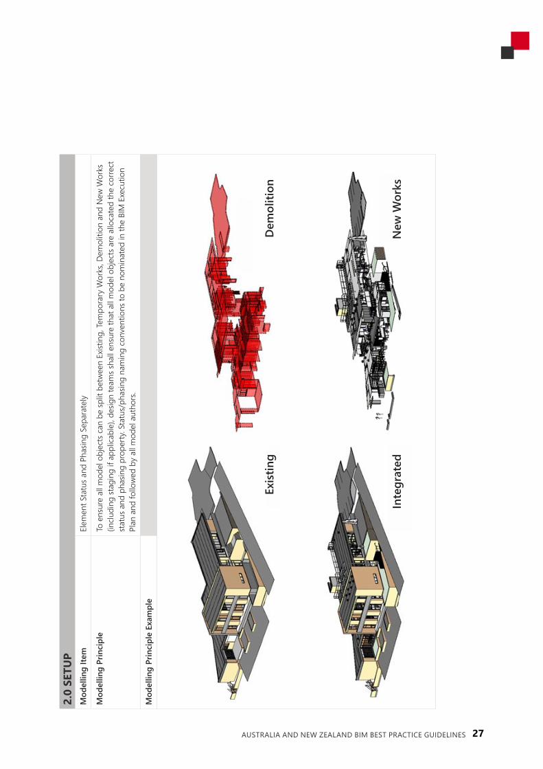
Item
Elem
ent S
tatu
s and
Pha
sing
Sepa
rate
ly
Mod
ellin
g Pr
inci
ple
To e
nsur
e al
l mod
el o
bjec
ts c
an b
e sp
lit b
etwe
en E
xistin
g, Te
mpo
rary
Wor
ks, D
emol
ition
and
New
Wor
ks
(inclu
ding
stag
ing
if ap
plica
ble)
, des
ign
team
s sha
ll en
sure
that
all
mod
el o
bjec
ts a
re a
lloca
ted
the
corre
ct
stat
us a
nd p
hasin
g pr
oper
ty. S
tatu
s/ph
asin
g na
min
g co
nven
tions
to b
e no
min
ated
in th
e BI
M E
xecu
tion
Plan
and
follo
wed
by a
ll m
odel
aut
hors
.
Mod
ellin
g Pr
inci
ple
Exam
ple
Dem
oliti
onEx
istin
g
Inte
grat
edN
ew W
orks

28 AUSTRALIA AND NEW ZEALAND BIM BEST PRACTICE GUIDELINES
Appendix B continued

29AUSTRALIA AND NEW ZEALAND BIM BEST PRACTICE GUIDELINES
2.0
SETU
PM
odel
ling
Item
AIQ
S &
NZI
QS
Elem
ent a
nd T
rade
Cla
ssific
atio
n Sy
stem
s (us
ed b
y Q
uant
ity S
urve
yors
)
Mod
ellin
g Pr
inci
ple
Mod
el E
lem
ent A
utho
r sha
ll ex
port
proj
ect fi
les w
ith th
e AI
QS
& N
ZIQ
S El
emen
t and
Tra
de C
lass
ificat
ion
Syst
ems a
dded
to th
e file
. The
MEA
shal
l lea
ve th
e Cl
assifi
catio
n se
lect
ion
as ‘u
ncla
ssifie
d’ to
ena
ble
the
Proj
ect Q
uant
ity S
urve
yor t
o m
ake
the
corre
ct se
lect
ion
when
they
rece
ive th
e file
.
Mod
ellin
g Pr
inci
ple
Exam
ple

30 AUSTRALIA AND NEW ZEALAND BIM BEST PRACTICE GUIDELINES
Appendix B continued
2.0
SETU
PM
odel
ling
Item
Cons
isten
t and
logi
cal (
accu
rate
) file
nam
ing
conv
entio
ns
Mod
ellin
g Pr
inci
ple
For e
ase
of u
se b
y th
e co
nsul
tant
team
, file
nam
ing
for e
ach
disc
iplin
e m
odel
shou
ld b
e co
nsist
ent a
s the
in
itial
file
nam
e th
roug
hout
the
proj
ect t
o al
low
seam
less
upd
ate
of m
odel
revis
ions
.
Mod
ellin
g Pr
inci
ple
Exam
ple
Imag
e Cr
edit:
BS1
192:2
007_
A2_2
016

31AUSTRALIA AND NEW ZEALAND BIM BEST PRACTICE GUIDELINES
2.0
SETU
PM
odel
ling
Item
Accu
rate
nam
ing
of o
bjec
ts a
nd e
lem
ents
Mod
ellin
g Pr
inci
ple
Obj
ect n
ames
shou
ld a
ccur
atel
y de
scrib
e th
e m
akeu
p, m
ater
ials,
and
size
of t
he o
bjec
t (e.
g. 10
mm
pbd
/9
2mm
stud
/10m
m p
bd)
Mod
ellin
g Pr
inci
ple
Exam
ple

32 AUSTRALIA AND NEW ZEALAND BIM BEST PRACTICE GUIDELINES
Appendix B continued

33AUSTRALIA AND NEW ZEALAND BIM BEST PRACTICE GUIDELINES
2.0
SETU
PM
odel
ling
Item
Corre
ct u
se o
f mod
ellin
g to
ols
Mod
ellin
g Pr
inci
ple
If a
Mod
el E
lem
ent A
utho
r use
s a n
on-s
tand
ard
tool
to c
reat
e th
e re
quire
d ge
omet
ry o
utpu
t the
y ne
ed
to e
nsur
e th
at th
e el
emen
t whe
n ex
porte
d ca
n be
iden
tified
cor
rect
ly by
rece
ivers
of t
he m
odel
. Thi
s is
achi
eved
thro
ugh
the
corre
ct a
pplic
atio
n of
the
rele
vant
IFC
Clas
sifica
tion.
Mod
ellin
g Pr
inci
ple
Exam
ple

34 AUSTRALIA AND NEW ZEALAND BIM BEST PRACTICE GUIDELINES
2.0
SETU
PM
odel
ling
Item
Iden
tifica
tion
of O
wne
rshi
p an
d Re
spon
sibilit
y
Mod
ellin
g Pr
inci
ple
Assig
n au
thor
of t
he o
bjec
t to
the
appr
opria
te d
iscip
line
(e.g
. Stru
ctur
al w
all t
o be
take
n fro
m st
ruct
ural
en
gine
er’s
desig
n, n
ot a
rchi
tect
’s dr
awin
g/m
odel
. The
use
of w
orks
ets c
an a
ssist
with
this
coor
dina
tion
prin
ciple
. Mod
el E
lem
ent A
utho
rs to
be
nom
inat
ed in
the
BIM
Exe
cutio
n Pl
an a
nd fo
llowe
d by
all
mod
el
auth
ors.
Mod
ellin
g Pr
inci
ple
Exam
ple
Anot
her c
omm
on e
xam
ple
othe
r tha
n th
e st
ruct
ural
vs a
rchi
tect
ural
mod
el is
whe
re th
e Ar
chite
ct a
nd
Elec
trica
l Eng
inee
r hav
e bo
th m
odel
led
elec
trica
l lig
htin
g. In
ord
er to
avo
id d
uplic
atio
n of
qua
ntiti
es, t
he
quan
tity
surv
eyor
shou
ld m
easu
re b
ased
on
resp
onsib
ility.
(resp
onsib
ility
mat
rix)
Appendix B continued

35AUSTRALIA AND NEW ZEALAND BIM BEST PRACTICE GUIDELINES
3.0
PLA
CEM
ENT
Mod
ellin
g Ite
mCo
rrect
gen
erat
ion
of e
lem
ent a
ssem
blie
s (pa
rts)
Mod
ellin
g Pr
inci
ple
Whe
n cr
eatin
g as
sem
blie
s, fo
r exa
mpl
e bu
ild-u
p of
com
posit
e ob
ject
s, co
rrect
use
of a
ssem
blie
s sha
ll be
ad
opte
d (e
.g. I
n a
plas
terb
oard
wal
l mod
el th
e as
sem
bly
with
fini
shes
, sub
stra
tes,
and
stru
ctur
es).
Mod
ellin
g Pr
inci
ple
Exam
ple
This
rela
tes t
o th
e Le
vel o
f Dev
elop
men
t et f
or th
e pr
ojec
t mod
el o
bjec
ts.

36 AUSTRALIA AND NEW ZEALAND BIM BEST PRACTICE GUIDELINES
Appendix B continued

37AUSTRALIA AND NEW ZEALAND BIM BEST PRACTICE GUIDELINES
3.0
PLA
CEM
ENT
Mod
ellin
g Ite
mSp
aces
& Z
ones
Mod
ellin
g Pr
inci
ple
Spac
es (R
evit
Room
s, AR
CHIC
AD Z
ones
) sho
uld
be m
odel
led
and
corre
ct d
ata
appl
ied
and
adde
d to
re
leva
nt B
uild
ing
Zone
s (Ap
artm
ent,
Smok
e, F
ire, F
unct
iona
l, Se
curit
y et
c).
Mod
ellin
g Pr
inci
ple
Exam
ple
Early
stag
e m
odel
use
d fo
r fun
ctio
nal a
rea
rate
s.

38 AUSTRALIA AND NEW ZEALAND BIM BEST PRACTICE GUIDELINES
3.0
PLA
CEM
ENT
Mod
ellin
g Ite
mSp
lit b
y flo
or le
vels
Mod
ellin
g Pr
inci
ple
To e
nsur
e al
l des
ign
mod
els c
an b
e ea
sily
and
read
ily e
xam
ined
, des
ign
team
s sha
ll re
fere
nce
the
exac
t sa
me
stor
ey le
vels
and
nam
ing.
Sto
rey
leve
ls an
d na
min
g to
be
nom
inat
ed in
the
BIM
Exe
cutio
n Pl
an a
nd
follo
wed
by a
ll m
odel
aut
hors
.
Mod
ellin
g Pr
inci
ple
Exam
ple
Mod
el o
bjec
ts fr
om sl
ab to
slab
not
floo
r to
roof
.
Appendix B continued

39AUSTRALIA AND NEW ZEALAND BIM BEST PRACTICE GUIDELINES
4.0
GEO
MET
RYM
odel
ling
Item
Qua
lity
and
Com
plet
enes
s of o
bjec
ts
Mod
ellin
g Pr
inci
ple
To e
nabl
e ap
prop
riate
and
relia
ble
info
rmat
ion
at th
e no
min
ated
tim
e, th
e m
odel
ling
of o
bjec
ts re
flect
ed
thro
ugh
desig
n ph
ases
shal
l con
sider
Lev
el o
f Dev
elop
men
t and
Lev
el o
f Inf
orm
atio
n re
quire
men
ts fo
r co
st p
lann
ing.
Obj
ects
and
ele
men
ts to
be
mod
elle
d to
nom
inat
ed L
evel
of D
evel
opm
ent a
nd L
evel
of
Info
rmat
ion
to b
e id
entifi
ed in
the
Mod
el E
lem
ent R
espo
nsib
ility
Tabl
e in
the
BIM
Exe
cutio
n Pl
an o
r Mod
el
Cont
ent P
lan
and
follo
wed
by a
ll m
odel
aut
hors
. Obj
ect/e
lem
ent r
elia
bilit
y ne
eds t
o be
com
mun
icate
d pr
ior t
o tra
nsm
ittin
g m
odel
.
Mod
ellin
g Pr
inci
ple
Exam
ple
Refe
r to
Bim
Foru
m L
evel
of D
etai
l spe
cifica
tions
and
Mod
el M
atrix
.

40 AUSTRALIA AND NEW ZEALAND BIM BEST PRACTICE GUIDELINES
4.0
GEO
MET
RYM
odel
ling
Item
Mod
el h
ow it
is to
be
cons
truct
ed
Mod
ellin
g Pr
inci
ple
Obj
ects
/ele
men
ts a
re to
be
mod
elle
d as
they
will
be c
onst
ruct
ed w
here
pra
ctica
l.
Mod
ellin
g Pr
inci
ple
Exam
ple
Inco
rrect
mod
ellin
g pr
actic
e de
fined
bel
ow
Sing
le m
odel
obj
ect s
hown
inclu
des s
teel
fram
e, c
olum
n an
d pa
d fo
otin
g al
l as o
ne o
bjec
t ele
men
t as o
ppos
ed to
indi
vidua
l ite
ms a
s it w
ould
be
cons
truct
ed.
Appendix B continued

41AUSTRALIA AND NEW ZEALAND BIM BEST PRACTICE GUIDELINES
4.0
GEO
MET
RY4
Mod
ellin
g Ite
m
Accu
rate
inhe
rent
geo
met
ry
Mod
ellin
g Pr
inci
ple
Nam
e ob
ject
s to
be c
onsis
tent
with
the
inhe
rent
geo
met
ry.
Mod
ellin
g Pr
inci
ple
Exam
ple
Inac
cura
te g
eom
etric
sizin
g in
nam
e sh
own
belo
w

42 AUSTRALIA AND NEW ZEALAND BIM BEST PRACTICE GUIDELINES
5.0
DAT
A (N
on-G
raph
ical
)M
odel
ling
Item
Clas
sifica
tion
Code
(use
d by
pro
ject
team
and
clie
nt)
Mod
ellin
g Pr
inci
ple
Appl
y ap
prop
riate
cla
ssific
atio
n co
de fo
r obj
ects
e.g
. uni
form
at, o
mni
class
, uni
class
.
Mod
ellin
g Pr
inci
ple
Exam
ple
Clas
sifica
tion
Syst
em a
nd le
vel o
f use
for e
ach
phas
e an
d el
emen
t typ
e to
be
agre
ed a
t out
set w
ith th
e pr
ojec
t tea
m a
nd id
entifi
ed/n
omin
ated
in th
e BI
M E
xecu
tion
Plan
and
follo
wed
by a
ll m
odel
aut
hors
.
UniC
lass
Exa
mpl
e
Appendix B continued

43AUSTRALIA AND NEW ZEALAND BIM BEST PRACTICE GUIDELINES

44 AUSTRALIA AND NEW ZEALAND BIM BEST PRACTICE GUIDELINES
5.0
DAT
A (N
on-G
raph
ical
)M
odel
ling
Item
Cons
isten
t and
logi
cal (
accu
rate
) obj
ect d
ata
Mod
ellin
g Pr
inci
ple
Ensu
ring
your
obj
ect d
ata
is co
nsist
ent a
nd a
ccur
ate
(e.g
. doo
rs, w
alls)
.
Mod
ellin
g Pr
inci
ple
Exam
ple
Split
for d
iffer
ent a
pplic
atio
ns.
Appendix B continued

45AUSTRALIA AND NEW ZEALAND BIM BEST PRACTICE GUIDELINES
6.0
PRO
CED
URE
SM
odel
ling
Item
Pro
vide
linke
d file
s
Mod
ellin
g Pr
inci
ple
Mod
els w
ith li
nked
file
shou
ld in
clude
sour
ce fi
le e
.g. q
uant
ities
may
not
be
inclu
ded
wher
e an
arc
hite
ct
has l
inke
d file
s for
a k
itche
n fit
out
(des
igne
d by
a d
iffer
ent t
eam
).
Mod
ellin
g Pr
inci
ple
Exam
ple
IFC2
x3 C
oord
inat
ion
View
Ver
sion
2.0
usin
g th
e Q
uant
ity Ta
ke-o
ff ad
d-on
vie
w

46 AUSTRALIA AND NEW ZEALAND BIM BEST PRACTICE GUIDELINES
6.0
PRO
CED
URE
SM
odel
ling
Item
Obj
ect p
lace
hold
ers
Mod
ellin
g Pr
inci
ple
In o
rder
for c
ost p
lann
ing
to a
void
dup
licat
ion
of o
bjec
ts re
quiri
ng p
ricin
g, c
reat
e wo
rkse
ts so
as t
o al
low
cons
ider
ed e
xpor
ts. F
or e
xam
ple
a di
ffuse
r in
the
Arch
itect
ural
mod
el m
ay b
e as
signe
d to
a M
echa
nica
l wo
rkse
t. A
bloc
k wa
ll in
the
Stru
ctur
al m
odel
may
be
assig
ned
to th
e Ar
chite
ctur
al w
orks
et. T
hese
can
be
switc
hed
off a
nd e
xpor
ted,
avo
idin
g do
uble
ups
.
Mod
ellin
g Pr
inci
ple
Exam
ple
Appendix B continued

47AUSTRALIA AND NEW ZEALAND BIM BEST PRACTICE GUIDELINES
6.0
PRO
CED
URE
SM
odel
ling
Item
Expo
rt of
mod
el p
roce
dure
Mod
ellin
g Pr
inci
ple
The
stan
dard
exp
ort i
n th
e au
thor
ing
softw
are
may
not
pro
vide
all r
equi
red
data
. Ens
ure
corre
ct e
xpor
t of
the
mod
el so
that
all
appr
opria
te d
ata
requ
ired
is co
ntai
ned
with
in m
odel
and
shee
ts.
Mod
ellin
g Pr
inci
ple
Exam
ple
Refe
r to
your
est
imat
ing
softw
are
prov
ider
for e
xpor
t pro
cedu
re
Revit
, arc
hica
d, if
c, dw
f, nw
d

48 AUSTRALIA AND NEW ZEALAND BIM BEST PRACTICE GUIDELINES
Appendix C BIM Execution Plan
Quality InformationDocument BIM EXECUTION PLAN Ref Prepared by Date Reviewed by
Revision History
Rev Revision Date DetailsAuthorised
Name/Position Signature
Project InformationProject name:
Project owner:
Project address/location:
Brief project description:
Contract type/delivery method:
Contractor engagement – indicative date:
Project ScheduleConcept design
Preliminary design
Developed design
Detailed design
Construction
Handover
Operation
Key Project ContactsRole Name Email
Quantity Surveying – Project Director
Quantity Surveying – Project Lead
Quantity Surveying – BIM Manager

49AUSTRALIA AND NEW ZEALAND BIM BEST PRACTICE GUIDELINES
QS and BIMIntroductionAs the project Quantity Surveyor (QS), *Company* is to use Building Information Models authored by the design team to support Quantification and Cost Estimation on this project. This will place greater value on the data review and validation process than the traditional approach (i.e. without BIM) with the added benefit of enabling the cost consultant to concentrate on delivering high-value project solutions.
Software & File Format*Company* will be using *software” for all cost planning outputs at the end of each design phase (as per Construction Industry Council (NZ) Guidelines or design contract deliverables). We require design information exchange files from each discipline for the uses outlined in the table below.
Software Required Design Information Exchange File Format Use
*Cost Planning Software” DWFx, IFC, DWG, PDF (Vector based)
Design tracking, cost planning and model data extraction
*Model Review Tool” IFC, NWD, DWFx Data auditing and visualisation
*Online Collaboration or Viewer Tool” DWFx, IFC, DWG, NWD Communication and collaboration
Modelling RequirementsAt agreed intervals, the design team is to provide progress models in “XXX” format for the QS to monitor design development to ensure that they have a comprehensive understanding of the project.
Design models should be developed with the QS requirements in mind with the key points:
• Model as how you would reasonably physically construct the building with greater emphasis in the later design phases.
• Exterior modelling vs. interior modelling. Objects are to be clearly identified in their naming and attributes should they be used in exterior envelope vs. interior construction.
• Consistent and logical object descriptions that can be reasonably understood.
• Material and Finish coding parameters are added to objects when appropriate. For Architecture we recommend a parameter/attribute code be inserted into object which should be linked to a schedule or specification.
• Minimal ‘Generic Model’ category objects as they often do not contain usable object data.
• No ‘in place’ or ‘placeholder’ objects at design phase milestones without appropriate communication to the QS BIM Manager and should be a subject of BIM Coordination meetings.
• Any objects that have not been modelled but will be as design progresses should be identified at each design phase milestone. A Gap register is a useful tool alongside a Model Content Plan (MCP).

50 AUSTRALIA AND NEW ZEALAND BIM BEST PRACTICE GUIDELINES
Key Object Parameters & Units of Measure (UOM)The key units of measure for geometric data extracted from objects are as in the table below. Generally, all object physical dimensions are driven from millimetres (mm) in one, two or three dimensions. All objects with an UOM of m² or m³ will need to be exported to three decimal places.
Parameter / AttributeObject UOM Cost Plan UOM
Cost Plan UseUnit Abbrev. Unit Abbrev.
Count Number No Number No Count of an object
Length Millimetres mm Metres m Length or of an object
Height Millimetres mm Millimetres mm Height of an object
Width Millimetres mm Millimetres mm Width of an object
Depth Millimetres mm Metres m Depth of an object
Perimeter Millimetres mm Metres m Length of a perimeter
Area Square metres m² Square metres m² Single face area of an object
Volume Cubic metres m³ Cubic metres m³ Volume of an object
Weight Kilograms kg Kilograms kg Weight of an object
Model Content Plan *Company* uses a Model Content Plan (MCP) for BIM projects to ensure that the design team understands elemental cost planning and object data expectations. A specific MCP will be created by the QS and reviewed by the design team. Once accepted, it will form a part of the overall project BIM Execution Plan.
QS Responsibilities*Company* will review any data in the model for its suitability for use in cost planning practice in conjunction with the project BIM Management/Execution Plan. As QS, *Company* is to include in their estimates non-modelled construction costs such as (but not limited to) design complexity, constructability, material supply, waste and non-modelled specified items. *Company* is to include for costs and other allowances such as (but not limited to) preliminaries, margins, escalation, procurement, contingencies, consents, consultant cost and other client side costs.
“Company” will not distribute any Building Information Models to other parties without written permission from the model owner and author.
The QS BIM Manager responsibilities include, but are not limited to:
• Verification that models are fit for purpose for quantity take off (QTO);
• Verification of QTO data for Cost Planning;
• Attendance at BIM meetings;
• Communication of issues back to the Project Participants;
• Reporting of model/design progress to their organisation;
• Organisation management of digital information for QS use.
Appendix C continued

51AUSTRALIA AND NEW ZEALAND BIM BEST PRACTICE GUIDELINES
This Appendix is an extract (Appendix C) of the NZ BIM Handbook, and is included with the permission of the NZ BIM Acceleration Committee.
Levels of Development1 GeneralLevel of Development (LOD) is a scale that can be used to show the reliability of content that is expected to be included for specific model elements at different times during model development. The main purpose of LOD when incorporated in Model Element Authoring (MEA) Schedules and BIM Execution Plans is to give clarity to each member of a design/construction team as to what they are required to author in their models at each stage and to what extent others can rely on them.
• LOD is a means of defining the extent to which a model element has been developed, from conception in the mind of the designer through to its construction and operation.
• The basis for the concept of LOD is recognition that model elements evolve at different rates throughout the design process. It follows that LOD should only be used to describe model elements, not models as a whole.
• LOD represents the extent to which information about an element can be relied on for decision-making purposes at a particular point in time.
• The value of LOD, incorporated in an Model Element Authoring Schedule, is that it provides a means of communicating expectations about the development of model elements between team members throughout the design and construction process for planning, management and coordination purposes.
• An element has only progressed to a given LOD when all stated requirements have been met. It should also be considered that the requirements are cumulative, i.e., any model element is required to have achieved all the requirements of the previous LOD.
The resources devoted to developing and maintaining Model Element Authoring Schedules should be proportional to the degree they assist management of the project. They are a tool, not an end in themselves.
It’s important to note there is no such thing as an “LOD ### model.” Project models at any stage of delivery will invariably contain elements and assemblies at various levels of development.
2 Level of development versus level of detailLOD is sometimes misinterpreted as level of detail rather than Level of Development. However, there are important differences. Level of detail is essentially how much detail is included in the model element. Level of Development is the degree to which the element’s geometry and attached information has been thought through – the degree to which project team members can rely on the information when using the model. In essence, level of detail can be thought of as input to the element, while Level of Development is reliable output.
3 LOD NotationsLOD notations are generally comprised of numbers at intervals of 100 to allow users of the system the flexibility to define intermediate LODs. LOD 350 is identified as a higher detailed coordination between
Appendix D Appendix C Levels of Development Definitions–NZBIMHandbook

52 AUSTRALIA AND NEW ZEALAND BIM BEST PRACTICE GUIDELINES
Appendix D continued
disciplines; higher than LOD 300 but not as high as LOD 400. Defining additional LODs can be crucial in some circumstances, particularly for contractual reasons, e.g., the handover of models from the design team to the construction team.
4 Aspects of LODLevel of Development as a concept is the sum of different aspects that define the information and geometry of each element, including:
4.1 Level of detail (LOd):Defines the level of geometric precision relative to the real object. For example, a highly detailed model of a chair may be considered to have a high level of detail. However, it may not be the correct size or have any information attached. Due to the graphic detail in the model it appears “complete” or well thought out. Unfortunately, Levels of Development have frequently been defined largely by reference to the level of detail. However, this can be a deceptive measure as a very detailed object can be placed into the model, but it may be the wrong object or the wrong size.
4.2 Level of accuracy (LOa):An object may be highly detailed, but it may be the wrong size, finalising a choice of construction or product as part of the design and, therefore, model development. For instance, a highly detailed air conditioning unit could be placed in the model at an early stage; it could represent the approximate likely footprint of the final air conditioning unit, but the same capacity unit could perhaps differ in size by 100mm or more. It is only once a final product selection is made that the accuracy of the object is determined. The issue of tolerance needs to be considered as part of this concept. A plasterboard wall will never be built to the same level of tolerance as a factory- assembled piece of laboratory equipment. If this is the case, this should be taken into account in the model. There is little point coordinating something to the nearest millimetre if construction techniques mean it can’t be built that way.
4.3 Level of information (LOi):Also referred to as level of data. In order to achieve true BIM and allow for use in 4D and Facilities Management, LOD needs to define what information is to be supplied with each element. This information could also relate to costing information at the beginning of the design, or engineering information for further analysis. The only comprehensive standard in this regard is the NATSPEC BOEM, which is highly complex and has not been very widely used in the industry.
4.4 Level of coordination (LOc):Is not defined as part of the element LOD but refers to the level of coordination with other model elements. A highly detailed door could be placed in an “architectural wall”; the door could contain the correct information for a specific LOD, but it might not be coordinated with the structural opening in the “structural wall”.
5LODDefinitionsIn the previous version of the Handbook, LOD 300 required that “Model elements are modelled as specific assemblies accurate in terms of quantity, size, shape…..”. The BIM Forum LOD 300 definition is less onerous.

53AUSTRALIA AND NEW ZEALAND BIM BEST PRACTICE GUIDELINES
The New Zealand BIM handbookThis document is one of a suite of documents forming the New Zealand BIM handbook.
You can download or view the remaining documents here:
https://www.biminnz.co.nz/bim-tools/
It requires that “The Model Element is graphically represented within the Model as a specific system, object or assembly in terms of quantity, size, shape…..”.
The BIM Forum states that for some elements LOD 300 requires “Modelled as design-specified size, shape…” and for LOD 350 “Modelled as actual size, shape…. The interpretation of these terms can have a significant impact on the type of documentation that needs to be produced. When specifying LODs it is recommended that the BIM Forum LOD specification is referenced.
MODEL CONTENT REQUIREMENTS
LOD 100 LOD 200 LOD 300 LOD 350 LOD 400 LOD 500
The Model Element may be graphically represented in the Model with a symbol or other generic representation, but does not satisfy the requirements for LOD 200.
Information related to the Model Element (i.e., cost per square metre, tonnage of HVAC, etc.) can be derived from other Model Elements.
The Model Element is graphically represented within the Model as a generic system, object or assembly with approximate quantities, size, shape, location and orientation. Non-graphic information may also be attached to the Model Element.
The Model Element is graphically represented within the Model as a specific system, object or assembly in terms of quantity, size, shape, location, and orientation.
Non-graphic information may also be attached to the Model Element.
The Model Element is graphically represented within the Model as a specific system, object, or assembly in terms of quantity, size, shape, location, orientation, and interfaces with other building systems. Non-graphic information may also be attached to the Model Element.
The Model Element is graphically represented within the Model as a specific system, object or assembly in terms of size, shape, location, quantity, and orientation with detailing, fabrication, assembly, and installation information. Non- graphic information may also be attached to the Model Element.
Refer to the BIM Forum LOD Specification for examples of graphical representation of the different LODs.

54 AUSTRALIA AND NEW ZEALAND BIM BEST PRACTICE GUIDELINES
ACKNOWLEDGEMENTS
AIQS and NZIQS acknowledges the support of the following organisations in the development of this Best Practice Guide.

55AUSTRALIA AND NEW ZEALAND BIM BEST PRACTICE GUIDELINES
