august 2009 volume no.7 storm technologies, inc
TRANSCRIPT
August2009 VolumeNo.7
STORMTECHNOLOGIES,INC.411NorthDepotStreetPOBox429
Albemarle,NC28002Phone:704/983-2040,Fax:704/982-9657
www.stormeng.com
The Impact of Furnace Performance on the Reliability of Superheater and Reheater Metals
Dick Storm, PE, Senior Consultant, Storm Technologies, Inc.
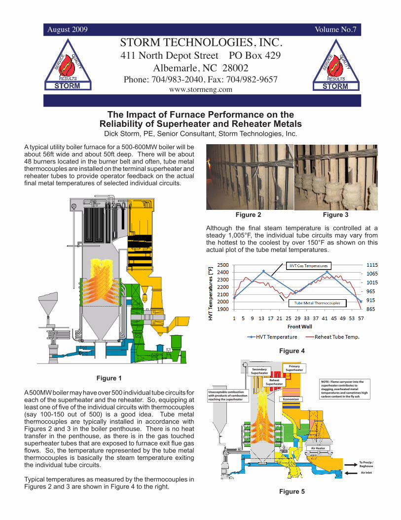
A typical utility boiler furnace for a 500-600MW boiler will be about 56ft wide and about 50ft deep. There will be about 48 burners located in the burner belt and often, tube metal thermocouples are installed on the terminal superheater and reheater tubes to provide operator feedback on the actual final metal temperatures of selected individual circuits.
Figure 1
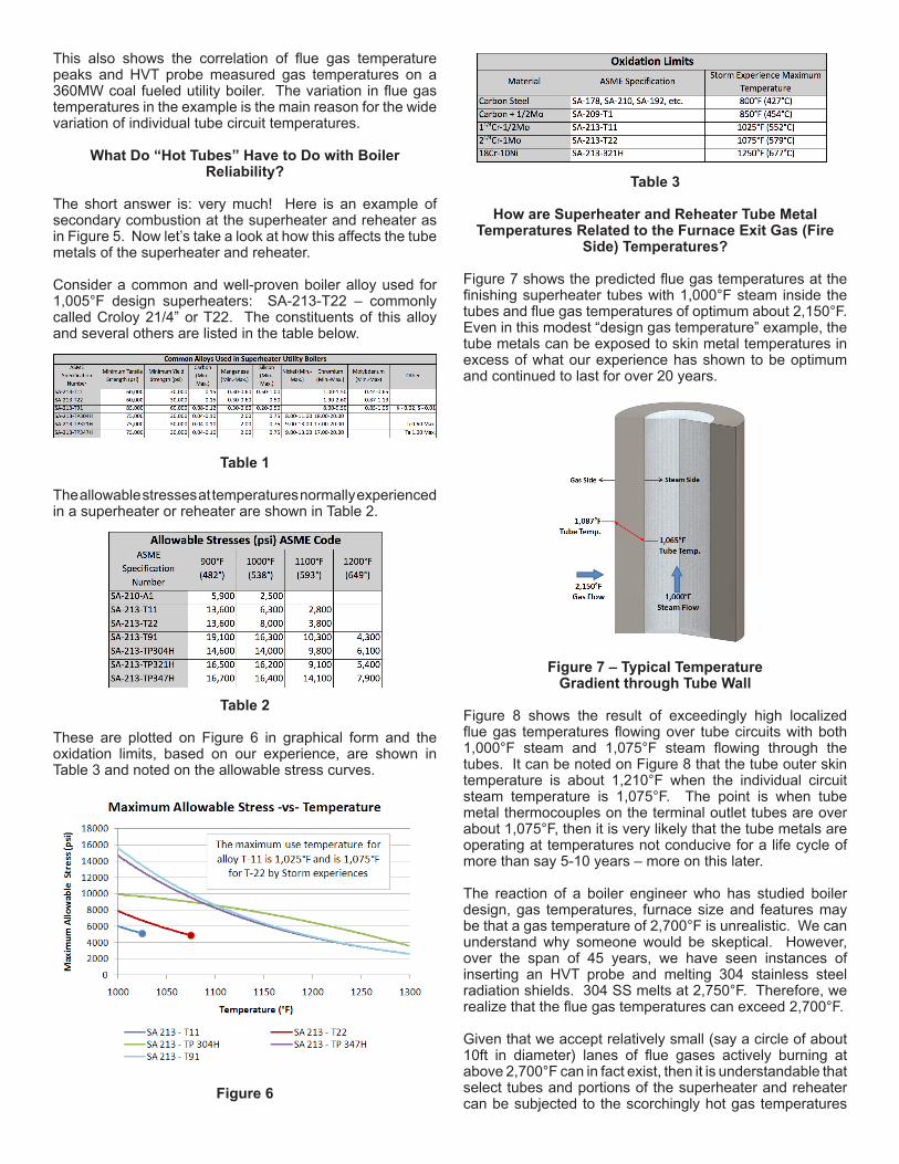
A 500MW boiler may have over 500 individual tube circuits for each of the superheater and the reheater. So, equipping at least one of five of the individual circuits with thermocouples (say 100-150 out of 500) is a good idea. Tube metal thermocouples are typically installed in accordance with Figures 2 and 3 in the boiler penthouse. There is no heat transfer in the penthouse, as there is in the gas touched superheater tubes that are exposed to furnace exit flue gas flows. So, the temperature represented by the tube metal thermocouples is basically the steam temperature exiting the individual tube circuits. Typical temperatures as measured by the thermocouples in Figures 2 and 3 are shown in Figure 4 to the right.
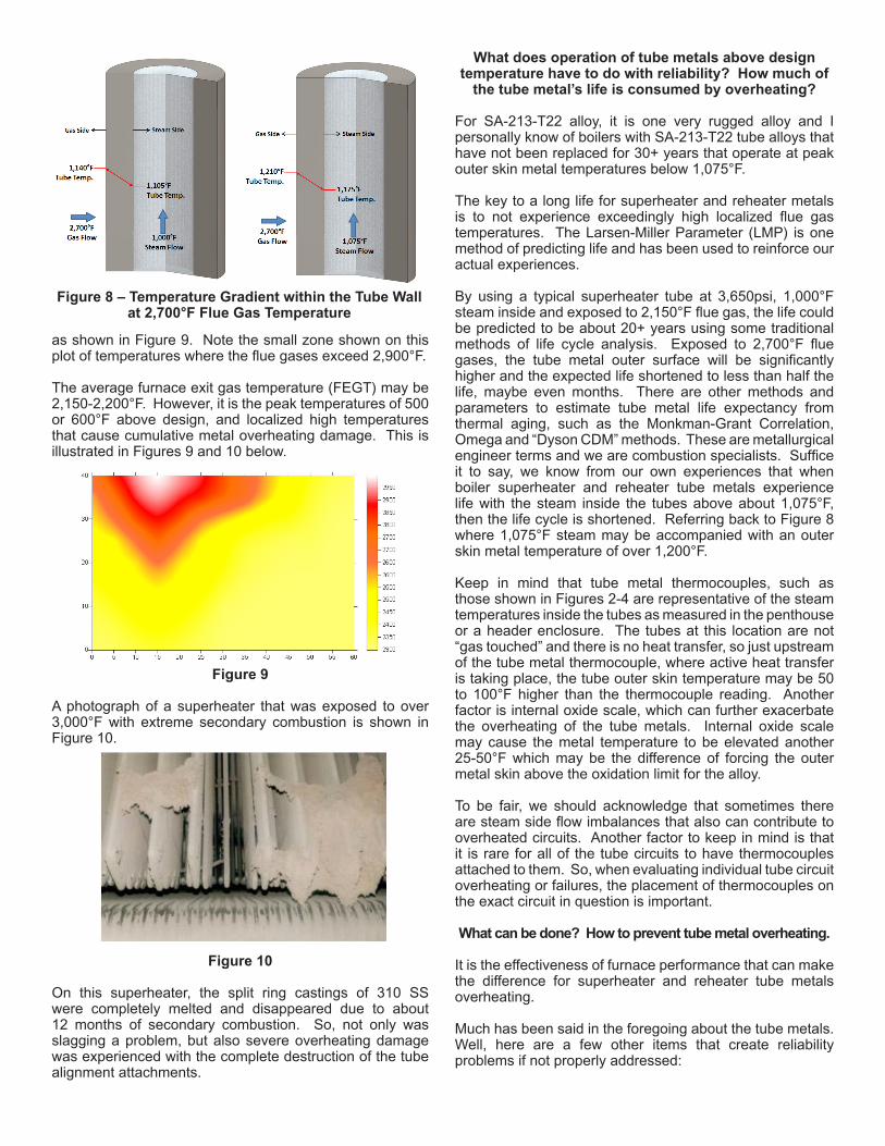
Although the final steam temperature is controlled at a steady 1,005°F, the individual tube circuits may vary from the hottest to the coolest by over 150°F as shown on this actual plot of the tube metal temperatures.
Figure 4
Figure 2 Figure 3
Secondary Superheater
Primary Superheater
Reheat Superheater
Economizer
Air Heater
Unacceptable combustion with products of combustion reaching the superheater
NOTE: Flame carryover into the superheater contributes to slagging, overheated metal temperatures and sometimes high carbon content in the fly ash
To Precip / Baghouse
Air Inlet
Figure 5
This also shows the correlation of flue gas temperature peaks and HVT probe measured gas temperatures on a 360MW coal fueled utility boiler. The variation in flue gas temperatures in the example is the main reason for the wide variation of individual tube circuit temperatures.
What Do “Hot Tubes” Have to Do with Boiler Reliability?
The short answer is: very much! Here is an example of secondary combustion at the superheater and reheater as in Figure 5. Now let’s take a look at how this affects the tube metals of the superheater and reheater. Consider a common and well-proven boiler alloy used for 1,005°F design superheaters: SA-213-T22 – commonly called Croloy 21/4” or T22. The constituents of this alloy and several others are listed in the table below.
Table 1
The allowable stresses at temperatures normally experienced in a superheater or reheater are shown in Table 2.
Table 2
These are plotted on Figure 6 in graphical form and the oxidation limits, based on our experience, are shown in Table 3 and noted on the allowable stress curves.
Figure 6
Table 3
How are Superheater and Reheater Tube Metal Temperatures Related to the Furnace Exit Gas (Fire
Side) Temperatures?
Figure 7 shows the predicted flue gas temperatures at the finishing superheater tubes with 1,000°F steam inside the tubes and flue gas temperatures of optimum about 2,150°F. Even in this modest “design gas temperature” example, the tube metals can be exposed to skin metal temperatures in excess of what our experience has shown to be optimum and continued to last for over 20 years.
Figure 7 – Typical Temperature Gradient through Tube Wall
Figure 8 shows the result of exceedingly high localized flue gas temperatures flowing over tube circuits with both 1,000°F steam and 1,075°F steam flowing through the tubes. It can be noted on Figure 8 that the tube outer skin temperature is about 1,210°F when the individual circuit steam temperature is 1,075°F. The point is when tube metal thermocouples on the terminal outlet tubes are over about 1,075°F, then it is very likely that the tube metals are operating at temperatures not conducive for a life cycle of more than say 5-10 years – more on this later.
The reaction of a boiler engineer who has studied boiler design, gas temperatures, furnace size and features may be that a gas temperature of 2,700°F is unrealistic. We can understand why someone would be skeptical. However, over the span of 45 years, we have seen instances of inserting an HVT probe and melting 304 stainless steel radiation shields. 304 SS melts at 2,750°F. Therefore, we realize that the flue gas temperatures can exceed 2,700°F.
Given that we accept relatively small (say a circle of about 10ft in diameter) lanes of flue gases actively burning at above 2,700°F can in fact exist, then it is understandable that select tubes and portions of the superheater and reheater can be subjected to the scorchingly hot gas temperatures
as shown in Figure 9. Note the small zone shown on this plot of temperatures where the flue gases exceed 2,900°F.
The average furnace exit gas temperature (FEGT) may be 2,150-2,200°F. However, it is the peak temperatures of 500 or 600°F above design, and localized high temperatures that cause cumulative metal overheating damage. This is illustrated in Figures 9 and 10 below.
Figure 9
A photograph of a superheater that was exposed to over 3,000°F with extreme secondary combustion is shown in Figure 10.
Figure 10
On this superheater, the split ring castings of 310 SS were completely melted and disappeared due to about 12 months of secondary combustion. So, not only was slagging a problem, but also severe overheating damage was experienced with the complete destruction of the tube alignment attachments.
What does operation of tube metals above design temperature have to do with reliability? How much of
the tube metal’s life is consumed by overheating?
For SA-213-T22 alloy, it is one very rugged alloy and I personally know of boilers with SA-213-T22 tube alloys that have not been replaced for 30+ years that operate at peak outer skin metal temperatures below 1,075°F.
The key to a long life for superheater and reheater metals is to not experience exceedingly high localized flue gas temperatures. The Larsen-Miller Parameter (LMP) is one method of predicting life and has been used to reinforce our actual experiences.
By using a typical superheater tube at 3,650psi, 1,000°F steam inside and exposed to 2,150°F flue gas, the life could be predicted to be about 20+ years using some traditional methods of life cycle analysis. Exposed to 2,700°F flue gases, the tube metal outer surface will be significantly higher and the expected life shortened to less than half the life, maybe even months. There are other methods and parameters to estimate tube metal life expectancy from thermal aging, such as the Monkman-Grant Correlation, Omega and “Dyson CDM” methods. These are metallurgical engineer terms and we are combustion specialists. Suffice it to say, we know from our own experiences that when boiler superheater and reheater tube metals experience life with the steam inside the tubes above about 1,075°F, then the life cycle is shortened. Referring back to Figure 8 where 1,075°F steam may be accompanied with an outer skin metal temperature of over 1,200°F.
Keep in mind that tube metal thermocouples, such as those shown in Figures 2-4 are representative of the steam temperatures inside the tubes as measured in the penthouse or a header enclosure. The tubes at this location are not “gas touched” and there is no heat transfer, so just upstream of the tube metal thermocouple, where active heat transfer is taking place, the tube outer skin temperature may be 50 to 100°F higher than the thermocouple reading. Another factor is internal oxide scale, which can further exacerbate the overheating of the tube metals. Internal oxide scale may cause the metal temperature to be elevated another 25-50°F which may be the difference of forcing the outer metal skin above the oxidation limit for the alloy.
To be fair, we should acknowledge that sometimes there are steam side flow imbalances that also can contribute to overheated circuits. Another factor to keep in mind is that it is rare for all of the tube circuits to have thermocouples attached to them. So, when evaluating individual tube circuit overheating or failures, the placement of thermocouples on the exact circuit in question is important.
What can be done? How to prevent tube metal overheating.
It is the effectiveness of furnace performance that can make the difference for superheater and reheater tube metals overheating.
Much has been said in the foregoing about the tube metals. Well, here are a few other items that create reliability problems if not properly addressed:
Figure 8 – Temperature Gradient within the Tube Wall at 2,700°F Flue Gas Temperature

Tube alignment slip ties and split ring castingsBoiler slagging and waterwall deslagging or water canon useExcessive soot blower operation to mitigate the slaggingSuperheater and reheater tube erosion from soot blowingHeat rate, fouling, SCR fouling, draft losses, etc.
You have heard that Storm’s approach to combustion optimization is by getting the inputs to the furnace right. Yes, this is the path to ensure optimum metal temperatures at the superheater and reheater as well as all of the other reasons to optimize combustion. If you are interested in learning more and how the Storm approach to combustion optimization can lead to better reliability, heat rate capacity factor, fuels flexibility and improved stack emissions, give us a call or email! We would love to explain how using our resources can contribute to improvements that benefit your plant such as our APPLES program (Annual Plant Performance and Longevity Evaluation Services). Check our website for our approach to pulverizer and fuel line balancing as well as some case studies of past successes.
Yours very truly,
Contributions of many of the Storm Team, edited by
Richard F. StormSenior Consultant/CEOEmail: [email protected]
••
•
•
•
The STORM™ Solid Fuel Injection SystemApproach to Excellence in Coal-Fueled Combustion
Excellence in Pulverizer Performance and Fuel Line Balancing Results in Uniform
Flames Here for the Advantages of:
Less Tube Metal OverheatingImproved ReliabilityLess SlaggingLess FoulingBetter Flyash LOIReduced Dry Gas LossFuel FlexibilityReduced “POPCORN” Ash to SCRReduced “FEGT”Less De-Superheating Water FlowsReduced Sootblowing
•••••••••••
Microprocessor, Gravimetric, Load Cell STOCK® Coal Feeder
Desirable Air/Fuel Ratio 1.8 lb Air / lb Fuel
Pulverizers Mechanically Tuned to STORM™
Specifications
Pulverizer Throats to STORM™ Design
Parameters
Fuel Lines Checked for Fineness and Distribution by Periodic STORM®
Isokinetic Coal Sampler Testing
Fuel Line Orifice Housing for Balancing
Venturi by STORM™ with Hot “K” Calibration
The Storm HVT Trolley allows for a single person to conduct furnace monitoring on a routine basis. By measuring flue gas temperatures directly, tube metal remaining life can be managed for increased replacement schedules for superheaters and reheaters. Gas sampling gives you the tools to do this by insuring an oxidizing environment to decrease FEGTs and eliminate secondary combustion.