aucotec ag - s-6 mérnök kft.s6mernok.hu/old/eb_technical_overview_eng.pdftechnical overview...
TRANSCRIPT


AUCOTEC AG
Oldenburger Allee 24 D-30659 Hannover
Phone: +49 (0)511 61 03-0 Fax: +49 (0)511 61 40 74
Web: www.aucotec.com E-Mail: [email protected]
AUCOTEC, INC. 2570 Foxfield Road, Suite 105 St. Charles, Illinois 60174
Phone: +1 630 485 5600 Fax: +1 630 485 5602
Web: www.aucotec.com E-Mail: [email protected]
Issue: January, 2009
Copyright: All rights, especially the right of reproduction and distribution as well as translation, are reserved. No part of this book may be reproduced, stored in re-trieval system, or transmitted in any form or by any means, electronic, mechanical, photocopying, microfilming, recording, or otherwise, without prior permission from AUCOTEC AG.
Exclusion of liability: Texts and software have been prepared with the greatest of care. The publishers as well as the authors cannot assume any legal or other liability of any nature for potential faulty statements and their consequences, which shall apply also for the software potentially included.
Trademark: Engineering Base® is a registered trade mark of the AUCOTEC AG, Germany. Microsoft Office Visio®, Microsoft SQL Server and Windows® are reg-istered trade marks of Microsoft Corporation, USA.

Table of Contents I
Technical Overview Engineering Base © by AUCOTEC AG
Contents 1 Welcome to Engineering Base .......................................1
2 Features ...........................................................................2 2.1 Database Explorer ......................................................................2 2.2 Multi-Project Access...................................................................2 2.3 Revision Management ................................................................3 2.4 Translate Management (Dictionaries) ......................................3 2.5 Worksheets ..................................................................................4 2.6 Catalogs .......................................................................................5 2.7 Data Service.................................................................................6 2.8 Shortcut Menu ............................................................................6 2.9 Navigating....................................................................................7 2.10 Undo.............................................................................................8 2.11 Online Manual and Introduction ..............................................8 2.12 open system Computer Aided Selling (osCAS) ........................9 2.13 Wire Routing (FastWire) .........................................................10 2.14 Dynamic License Manager.......................................................10 2.15 Diagramming.............................................................................11 2.15.1 Microsoft Office Visio................................................................11 2.15.2 Drawing Borders and Title Blocks .............................................11 2.15.3 Automatic Labeling ....................................................................12 2.15.4 Master-Shapes.............................................................................13 2.15.5 Real-Time Cross-References ......................................................14 2.15.6 Smart Connections, StayConnect and AutoConnect ..................15 2.15.7 MultiPlace...................................................................................16 2.15.8 Insert Comments.........................................................................16 2.15.9 Insert Hyperlinks ........................................................................16 2.15.10 Insert Objects ..............................................................................17 2.15.11 Insert Pictures .............................................................................18 2.15.12 Layers .........................................................................................19 2.15.13 Scaling Diagrams........................................................................20 2.15.14 Printing .......................................................................................21 2.15.15 Multi-Window ............................................................................21

Table of Contents II
Technical Overview Engineering Base © by AUCOTEC AG
2.16 Reports.......................................................................................22 2.16.1 About Reports.............................................................................22 2.16.2 Cable Lists ..................................................................................22 2.16.3 Wiring Lists ................................................................................23 2.16.4 Terminal Block Diagram ............................................................23 2.16.5 Input / Output Lists.....................................................................23 2.16.6 Purchase Order Lists...................................................................23 2.16.7 Sheet Index .................................................................................23 2.16.8 Fuse Lists ....................................................................................23 2.16.9 Kitting Lists ................................................................................24 2.16.10 Overload Relay Settings Lists ....................................................24 2.16.11 Bill of Material ...........................................................................24 2.17 Sharing Information with other Users....................................25 2.17.1 Sharing Databases.......................................................................25 2.17.2 Multi-User Ability ......................................................................25 2.17.3 User Management .......................................................................25 2.18 Sharing Information with other Programs ............................26 2.18.1 AutoCAD (DWG/DXF)..............................................................26 2.18.2 Excel (XLS) ................................................................................26 2.18.3 Portable Document Format (PDF)..............................................26 2.18.4 SolidWorks .................................................................................27 2.18.5 CATIA V5 ..................................................................................28 2.18.6 SAP Communication Framework...............................................28 2.18.7 Additional Formats .....................................................................28 2.18.8 Automation Framework..............................................................28 2.18.9 Hardware Configuration Link.....................................................29 2.18.10 Label Designer............................................................................29 2.18.11 Terminal Rail Designer...............................................................30 2.18.12 Insert Files ..................................................................................30 2.19 Document Styles........................................................................31 2.19.1 Fluid Diagrams ...........................................................................31 2.19.2 Circuit Diagrams.........................................................................32 2.19.3 HookUps.....................................................................................32 2.19.4 Hydraulic / Pneumatic Diagrams................................................33 2.19.5 Layout Diagrams ........................................................................33
Table of Contents III
Technical Overview Engineering Base © by AUCOTEC AG
2.19.6 Logic Diagrams ..........................................................................34 2.19.7 Loop Diagrams ...........................................................................35 2.19.8 P&I Diagrams .............................................................................36 2.19.9 Single-Line Diagrams.................................................................36 2.19.10 Specification Sheets....................................................................36 2.19.11 Wiring Diagrams ........................................................................37 2.19.12 Tag Sheets...................................................................................37 2.20 Wizards and Tools ....................................................................38 2.20.1 About Wizards and Tools ...........................................................38 2.20.2 Cable Wizard ..............................................................................39 2.20.3 Structure Catalog ........................................................................39 2.20.4 Merge I/O Wizard.......................................................................40 2.20.5 Multi Terminal Block Diagram Wizard......................................40 2.20.6 Quality Management Tool ..........................................................41 2.20.7 Relay and Contactor Wizard.......................................................42 2.20.8 Terminal Block Wizard ..............................................................43 2.20.9 Typical Select and Typical Copy................................................44 2.20.10 Update Dialog from Type Wizard ..............................................45 2.20.11 Update from Catalog Wizard......................................................45 2.20.12 PLC Address Wizard ..................................................................46 2.20.13 PROFIBUS Configurator............................................................47 2.20.14 Price Calculation.........................................................................47 2.20.15 Swap Labels................................................................................47 2.20.16 Dimensioning..............................................................................48 2.20.17 Assign Wires to Cables Automatically .......................................48 2.20.18 Assign Wires to Cables Manually ..............................................48 2.20.19 Special Reports for Cables and Wires ........................................48 2.20.20 Copy Attributes from Project to Wires .......................................48 2.20.21 Replace Text with Reference to Dictionary................................48 2.20.22 XLS Configurator .......................................................................48 2.20.23 Import and update items .............................................................48 2.21 System Architecture .................................................................49 2.21.1 Object-Oriented ..........................................................................49 2.21.2 Three-Tier Client/Server Architecture........................................49 2.21.3 Microsoft SQL Server.................................................................51

Table of Contents IV
Technical Overview Engineering Base © by AUCOTEC AG
2.21.4 Unicode.......................................................................................52 2.21.5 Attributes and Dialogs ................................................................52 2.21.6 Integrated VBA Development System .......................................52 2.21.7 Application Programming Interface ...........................................53 2.21.8 Localized Versions .....................................................................53 2.22 Feature Comparison Chart......................................................54
3 Licenses..........................................................................60 3.1 Licensing Comparison Chart...................................................60 3.2 EB Evaluation Version .............................................................62 3.3 EB View .....................................................................................62 3.4 EB Electrical..............................................................................62 3.5 EB Electrical Pro ......................................................................62 3.6 EB Plant Design ........................................................................62 3.7 EB Instrumentation Basic ........................................................62 3.8 EB Instrumentation Pro...........................................................62 3.9 EB Cable ....................................................................................63 3.10 EB Power ...................................................................................63 3.11 EB Fluid.....................................................................................63
4 Industry Solutions ........................................................64 4.1 Engineering and Process Control............................................64 4.2 Wiring Harness Development..................................................64 4.3 Power Generation and Distribution........................................65 4.4 Industrial Plant and Machine Design .....................................65 4.5 Sample Documents....................................................................66
Welcome to Engineering Base 1
Technical Overview Engineering Base © by AUCOTEC AG
1 Welcome to Engineering Base Strong Basis for New Solutions
Systems for the documentation of electrical engineering systems have been on the market for over 20 years. AUCOTEC has been involved from the very start. At that time the computer was used like an intelligent drawing board. In addition, the first ECAD systems offered users functions that also took into account logical relations to exclude sources of error.
The limits of conventional E-CAD systems lie in their dependence on graphic repre-sentation. For instance, lists are complete and correct only as long as the diagrams actually represent the complete plant. The forced dependence of the work sequence on graphic representation carries even more weight, however, since in the actual planning process devices and plant structure are specified long before they are repre-sented in the circuit diagrams.
Engineering Base (EB) sets new standards because as a product of the most recent ECAE generation it offers unique editing options – due to the independence of the plant model from graphic representations and the independence of the users regard-ing their work sequence. An always up-to-date plant model enables this degree of freedom because all objects such as devices, cables and leads but also functions, graphic documents and catalogs are kept in it with all their references. Whenever a piece of information is available, it is put into the model via input masks, list editing or graphic representation and supplemented later on by further representations or details. Thus emerge the complete planning and documentation of electrical systems in diverse industrial sectors: from the first concepts and basic information down to the last refinement – and all that under permanent supervision.
January, 2009

Features 2
Technical Overview Engineering Base © by AUCOTEC AG
2 Features 2.1 Database Explorer The Database Explorer is the main window of the Engineering Base application and gives the user easy access to all data stored in the database. From the Database Ex-plorer, the user can easily navigate between projects and create or modify data.
The Database Explorer has the familiar look and feel of the well known Microsoft Windows Explorer. Thus cutting down the time required to become familiar with Engineering Base.
2.2 Multi-Project Access Within Engineering Base, all design work is organized into projects. All diagrams and component data is stored in those projects. Because the user has simultaneous access to all projects within the database, diagrams and components can easily be copied between projects.
Multi-project

Features 3
Technical Overview Engineering Base © by AUCOTEC AG
2.3 Revision Management Revision Management makes all changes within a project traceable and creates clearly arranged reports for manufacturing purposes.
Revision worksheet for wires
2.4 Translate Management (Dictionaries) With Translate Management, all text is maintained in dictionaries and can be ex-changed as Excel (.xls) files for translation.
Text shown on diagrams, reports and worksheets can easily be switched from one language to another. The number of languages displayed on the diagram at the same time is only limited by the physical space on the diagram. The total number of lan-guages managed by the system is not limited.
Translate Management

Features 4
Technical Overview Engineering Base © by AUCOTEC AG
2.5 Worksheets Based on information stored in the Engineering Base database, worksheets for Bill of Materials, Purchase Order Lists, Wiring Lists, etc. reflect changes in real-time (no batch-runs required). Worksheets can be used for modifying data, printing, and ex-porting (e.g. XLS).
New worksheets can be created quickly by adding or removing columns. Data in the worksheet can also be filtered, sorted, and counted.
Engineering Base Workbook with Worksheets
Pre-defined Worksheets include
• Bill of Material • Cable lists (including from-to information) • Wiring lists (including from-to information) • Input / Output lists • Motor lists • Purchase Order list • Sheet index • Fuse list • Kitting list • Overload Relay Settings list

Features 5
Technical Overview Engineering Base © by AUCOTEC AG
2.6 Catalogs Engineering and purchasing data for all components including devices, enclosures and cables is stored in database catalogs, providing all necessary properties and suit-able shapes for diagrams and layouts.
From the catalog, components can be used directly in the project by copying them in the Database Explorer or simply placing the shape in the diagram.
Components that are not found in the catalog can be downloaded from the AUCOTEC Data Service.
Catalog

Features 6
Technical Overview Engineering Base © by AUCOTEC AG
2.7 Data Service With its Data Service, AUCOTEC provides a valuable service to the user. Ready-to-use component data and shapes for various manufacturers can be downloaded from our web site at http://www.aucotec.com/index.php?module=DataService.
Some of the manufacturers with component information available from the Data Service are:
Data Service
2.8 Shortcut Menu The shortcut menu (context menu) for each item is just a right click away, and pro-vides quick access to the most common commands.
Shortcut menu

Features 7
Technical Overview Engineering Base © by AUCOTEC AG
2.9 Navigating Items can be found quickly in the Database Explorer by using the Navigate com-mand at the shape on the diagram. Diagrams can also be opened directly from the link at the device in the Database Explorer by using the Open with Visio command or from the cross-reference in worksheets.
Navigate command
Open with Visio command from link in Database Explorer
Open with Visio command from reference in worksheet

Features 8
Technical Overview Engineering Base © by AUCOTEC AG
2.10 Undo Undo is available with multi-undo steps in the Database Explorer and in Visio. Undo is a safety net for the user. The user can easily try functions without the risk of los-ing data.
2.11 Online Manual and Introduction Engineering Base offers the user a context sensitive help system that can be ac-cessed directly from the shortcut menu on any item.
Context sensitive help from the Templates folder
For the beginner, an introductory segment offers the user a quick overview with an-imations and screen videos. It takes just a few minutes to get familiar with the idea, the benefits and the handling of Engineering Base.
Features 9
Technical Overview Engineering Base © by AUCOTEC AG
2.12 open system Computer Aided Selling (osCAS)
Projecting simultaneously when Selling - with osCAS
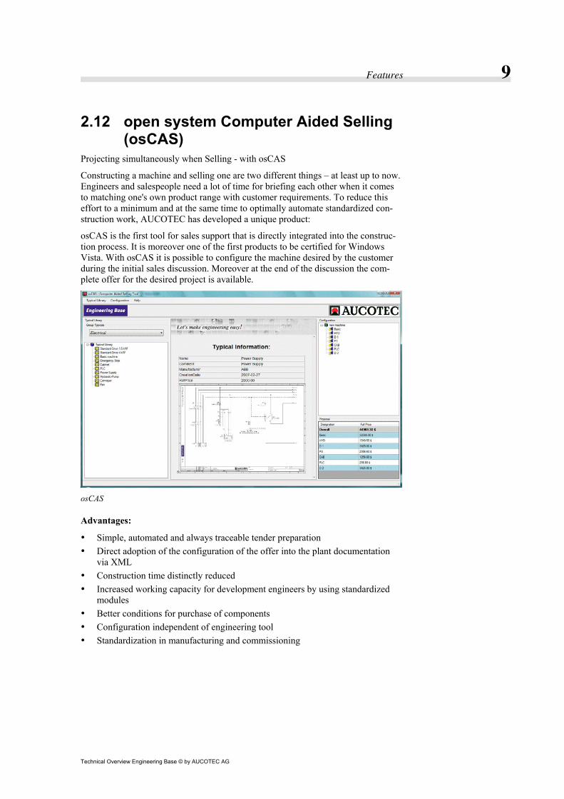
Constructing a machine and selling one are two different things – at least up to now. Engineers and salespeople need a lot of time for briefing each other when it comes to matching one's own product range with customer requirements. To reduce this effort to a minimum and at the same time to optimally automate standardized con-struction work, AUCOTEC has developed a unique product:
osCAS is the first tool for sales support that is directly integrated into the construc-tion process. It is moreover one of the first products to be certified for Windows Vista. With osCAS it is possible to configure the machine desired by the customer during the initial sales discussion. Moreover at the end of the discussion the com-plete offer for the desired project is available.
osCAS
Advantages:
• Simple, automated and always traceable tender preparation • Direct adoption of the configuration of the offer into the plant documentation
via XML • Construction time distinctly reduced • Increased working capacity for development engineers by using standardized
modules • Better conditions for purchase of components • Configuration independent of engineering tool • Standardization in manufacturing and commissioning

Features 10
Technical Overview Engineering Base © by AUCOTEC AG
2.13 Wire Routing (FastWire) FastWire calculates the length for each individual wire based on the placement of the components and cable ducting in the layout diagram. Thus providing all required data for quick and accurate wiring.
2.14 Dynamic License Manager The Dynamic License Manager allows the user to enable and disable individual li-censes and to detach time-limited licenses from the network to use them off-site.

Features 11
Technical Overview Engineering Base © by AUCOTEC AG
2.15 Diagramming
2.15.1 Microsoft Office Visio Visio is the office diagramming solution from Microsoft. Visio is intuitive and easy to use without the overhead of full featured CAD systems. Users who are familiar with Microsoft Office use Visio with little training. Visio is designed to create dia-grams using intelligent shapes and connections - the ideal basis for electrical engi-neering.
2.15.2 Drawing Borders and Title Blocks Pre-defined drawing borders with title blocks are available in various standard ISO / IEC and ANSI sizes. They can be modified in every aspect to match industry and customer requirements.
Text blocks with information from the project or drawing can be used in title blocks to reduce the time required for global changes. Information is entered at the project level and automatically shown on all sheets and reports within that project.
Features 12
Technical Overview Engineering Base © by AUCOTEC AG
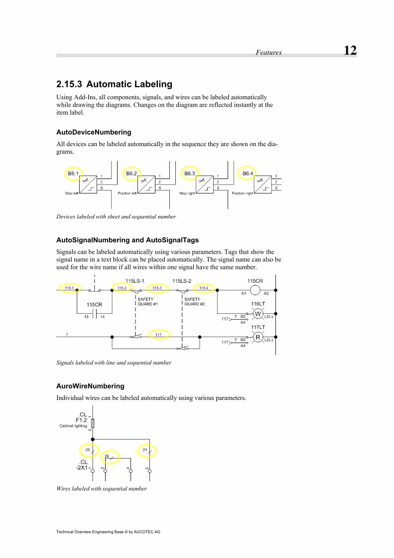
2.15.3 Automatic Labeling Using Add-Ins, all components, signals, and wires can be labeled automatically while drawing the diagrams. Changes on the diagram are reflected instantly at the item label.
AutoDeviceNumbering All devices can be labeled automatically in the sequence they are shown on the dia-grams.
Devices labeled with sheet and sequential number
AutoSignalNumbering and AutoSignalTags Signals can be labeled automatically using various parameters. Tags that show the signal name in a text block can be placed automatically. The signal name can also be used for the wire name if all wires within one signal have the same number.
Signals labeled with line and sequential number
AuroWireNumbering Individual wires can be labeled automatically using various parameters.
Wires labeled with sequential number
Features 13
Technical Overview Engineering Base © by AUCOTEC AG
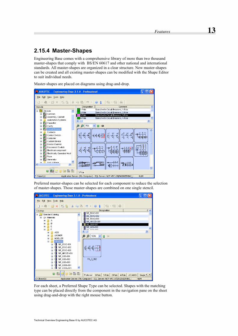
2.15.4 Master-Shapes Engineering Base comes with a comprehensive library of more than two thousand master-shapes that comply with BS/EN 60617 and other national and international standards. All master-shapes are organized in a clear structure. New master-shapes can be created and all existing master-shapes can be modified with the Shape Editor to suit individual needs.
Master-shapes are placed on diagrams using drag-and-drop.
Preferred master-shapes can be selected for each component to reduce the selection of master-shapes. Those master-shapes are combined on one single stencil.
For each sheet, a Preferred Shape Type can be selected. Shapes with the matching type can be placed directly from the component in the navigation pane on the sheet using drag-and-drop with the right mouse button.

Features 14
Technical Overview Engineering Base © by AUCOTEC AG
2.15.5 Real-Time Cross-References All cross-references (e.g. between contact and relay or at potentials) are updated in real-time. Moving a shape to another sheet, the cross-references are instantly up-dated. This improves the quality of the documentation dramatically by eliminating all errors in cross-referencing. All documentation will be free of mismatches. The system also allows for navigation between documents along cross-references throughout the entire project.

Features 15
Technical Overview Engineering Base © by AUCOTEC AG
2.15.6 Smart Connections, StayConnect and AutoConnect
Connections in Visio are smart. They break-off if a shape is placed into an existing connection and they automatically heal if the shape is removed.
StayConnect With StayConnect, moving a shape moves all connections with the shape.
StayConnect keeps all connections with the shape
AutoConnect With AutoConnect, placing a shape automatically creates all connections.
AutoConnect creates connections
Features 16
Technical Overview Engineering Base © by AUCOTEC AG
2.15.7 MultiPlace The MultiPlace feature allows you to select multiple components in the Explorer or Worksheet and drop them with one single operation.
MultiPlace
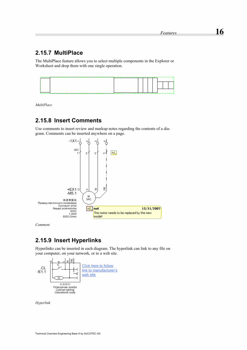
2.15.8 Insert Comments Use comments to insert review and markup notes regarding the contents of a dia-gram. Comments can be inserted anywhere on a page.
Comment
2.15.9 Insert Hyperlinks Hyperlinks can be inserted in each diagram. The hyperlink can link to any file on your computer, on your network, or to a web site.
Hyperlink

Features 17
Technical Overview Engineering Base © by AUCOTEC AG
2.15.10 Insert Objects Linked objects or embedded objects can be used to add all or part of a file created in a Microsoft Office System program, or in any program that supports linked and em-bedded objects.
If the file was created with a program that is compatible with Object Linking and Embedding (OLE), it opens in place in the Microsoft Office Visio diagram. Other-wise, the program opens in its own window.
Embedded Microsoft Office Excel chart with In-Place editing

Features 18
Technical Overview Engineering Base © by AUCOTEC AG
2.15.11 Insert Pictures Existing graphics can be easily inserted into diagrams. For example, a company logo can be added to the title block or a photograph of a panel can be added to the panel layout.
Once the graphics are in the diagram, they can be rotated, moved, resized, and grouped, just as you can with other shapes. For all graphics file types (except meta-files), the image can be modified by adjusting the brightness, contrast, transparency, as well as many other settings. Metafiles can be modified by first converting them into a Visio shape.
The following graphics file formats are supported:
• Compressed Enhanced Metafile (.emz) • Enhanced Metafile (.emf) • Graphics Interchange Format (.gif) • JPEG File Interchange Format (.jpg) • Portable Network Graphics (.png) • Scalable Vector Graphics Drawing (.svg, .svgz) • Tag Image File Format (.tif, .tiff) • Windows Bitmap (.bmp, .dib) • Windows Metafile (.wmf)
Inserted JPEG file

Features 19
Technical Overview Engineering Base © by AUCOTEC AG
2.15.12 Layers Layers can be used to organize related shapes on a diagram. By assigning shapes to different layers, they can be selectively viewed, printed, colored, and locked.
A shape can be assigned to multiple layers or to no layers, and every diagram can have a different set of layers.
Layer Properties dialog
Features 20
Technical Overview Engineering Base © by AUCOTEC AG
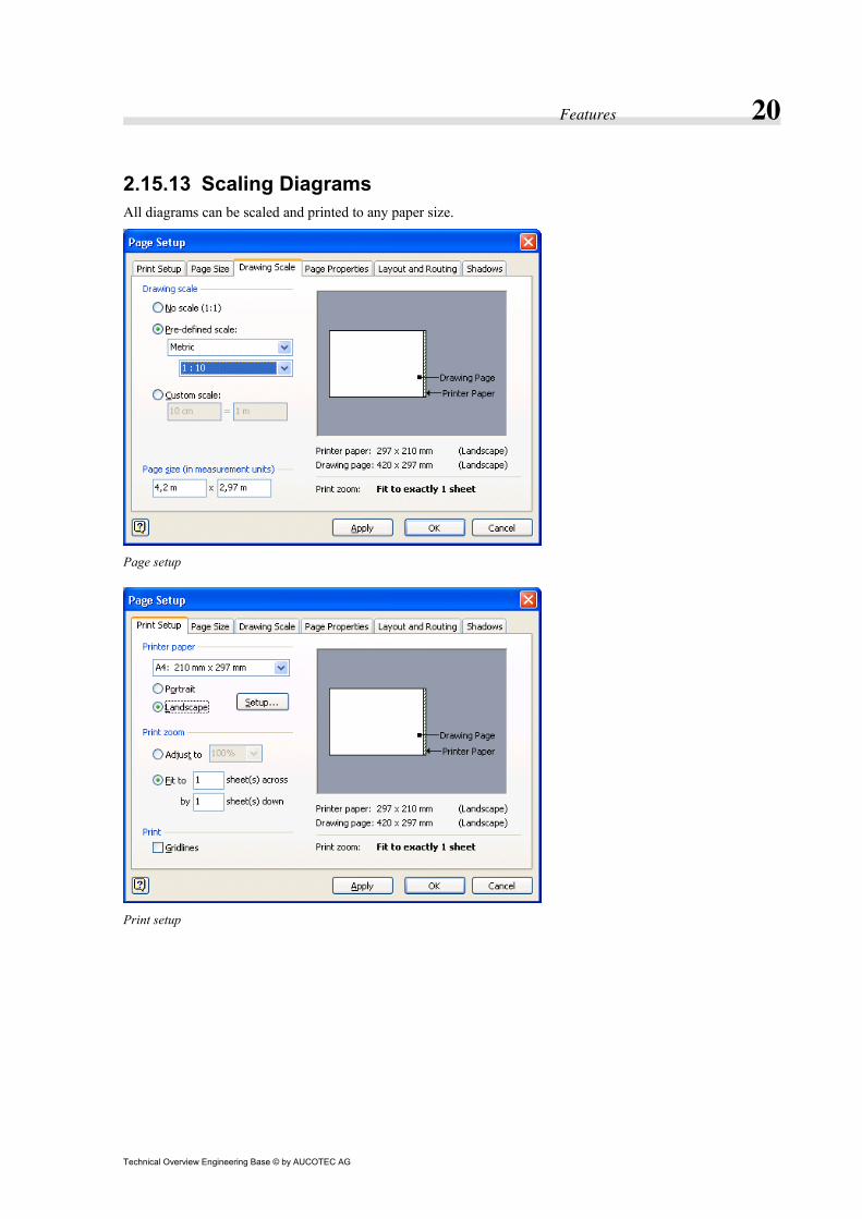
2.15.13 Scaling Diagrams All diagrams can be scaled and printed to any paper size.
Page setup
Print setup

Features 21
Technical Overview Engineering Base © by AUCOTEC AG
2.15.14 Printing All diagrams can be printed individually or collectively with one single print job.
2.15.15 Multi-Window Multiple diagrams can be opened simultaneously. This makes it extremely simple to move objects or areas from one diagram to another or even copy an object or area from one project to another.
Multi-Window

Features 22
Technical Overview Engineering Base © by AUCOTEC AG
2.16 Reports
2.16.1 About Reports Any worksheet can be inserted as a report on a diagram, making it a part of the pro-ject documentation. Information in reports is always updated and can be edited di-rectly on the diagram.
Pre-defined reports include:
• Cable Lists • Wiring Lists • Terminal Block Diagram • Input / Output Lists • Purchase Order Lists • Sheets Index • Fuse Lists • Kitting Lists • Overload Relay Settings Lists • Bill of Material
Sample report
2.16.2 Cable Lists Cable lists include information about the cable including from-to information. In-formation about the cable and from-to information can be edited directly in the re-port.

Features 23
Technical Overview Engineering Base © by AUCOTEC AG
2.16.3 Wiring Lists Wiring lists include information about the wires including from-to information and cross-references to the circuit diagram. Information about the wire can be edited directly in the report.
2.16.4 Terminal Block Diagram Terminal block diagrams include information about terminals with jumpers and wir-ing.
Terminal block diagram
2.16.5 Input / Output Lists Input / Output lists include information about the inputs and outputs of control sys-tems. Information about the inputs and outputs can be edited directly in the report.
2.16.6 Purchase Order Lists Purchase order lists include purchasing information about the items that need to be ordered. Information about the items can be edited directly in the report.
2.16.7 Sheet Index Sheets index lists include information about sheets. Information about the sheets can be edited directly in the report.
2.16.8 Fuse Lists Fuse lists include information about fuses. Information about fuses can be edited directly in the report.

Features 24
Technical Overview Engineering Base © by AUCOTEC AG
2.16.9 Kitting Lists Kitting lists include information about components with cross-references to circuit diagram and panel layout. Information about components can be edited directly in the report.
2.16.10 Overload Relay Settings Lists Overload Relay Settings lists include information about overload relays and their settings. Information about overload relays can be edited directly in the report.
2.16.11 Bill of Material A Bill of material list (BOM) includes information about components, such as: the manufacturer’s name, catalog number and cross-references to the circuit diagram. Information about components can be edited directly in the report.
Bill of Material

Features 25
Technical Overview Engineering Base © by AUCOTEC AG
2.17 Sharing Information with other Users
2.17.1 Sharing Databases Users can interactively connect to any database on the server to share projects, cata-logs, and stencils with other users. Basic access permissions are administrated by the network administrator. More detailed access permissions are administrated directly in the Engineering Base Database Explorer and can be handled directly by the user.
Projects, catalogs, and stencils can be transferred between databases using XML files; containing all required data in one single file.
Sharing databases
2.17.2 Multi-User Ability Several users can work with the same project simultaneously to speed up the process of creating the required documentation. While one user is drawing control diagrams, another user might be drawing the panel layout.
2.17.3 User Management User Management prevents unauthorized access to areas of the database. Individual users and groups can be administrated for accessing projects, catalogs, stencils and other data.
User management

Features 26
Technical Overview Engineering Base © by AUCOTEC AG
2.18 Sharing Information with other Programs
2.18.1 AutoCAD (DWG/DXF) To exchange drawings with suppliers and customers, the DWG and DXF file for-mats developed by Autodesk are widely accepted industry standards. Engineering Base supports both standards with import and export filters. Individual sheets and complete projects can be exported to improve cooperation with engineering partners and customers.
2.18.2 Excel (XLS) To exchange alphanumerical information with suppliers and customers, the XLS file format developed by Microsoft is a widely accepted industry standard. Engineering Base supports this standard with import and export filters.
Information from projects and catalogs can be imported and exported to improve cooperation with engineering partners and customers.
The Update from Excel wizard also allows updating information from an Excel file.
2.18.3 Portable Document Format (PDF) To easier exchange information with suppliers and customers, the PDF (Portable Document Format) file format developed by Adobe, is a widely accepted industry standard. Engineering Base supports this standard with an export filter.
With the PDF Viewing license, complete projects including information for navigat-ing can be exported to a single PDF file for viewing in the Adobe Reader.

Features 27
Technical Overview Engineering Base © by AUCOTEC AG
2.18.4 SolidWorks Data can be exchanged with SolidWorks for panel layout and wiring.
Features 28
Technical Overview Engineering Base © by AUCOTEC AG
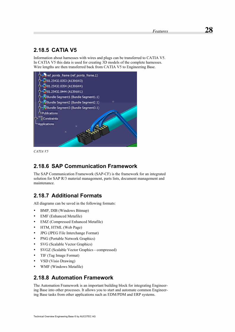
2.18.5 CATIA V5 Information about harnesses with wires and plugs can be transferred to CATIA V5. In CATIA V5 this data is used for creating 3D models of the complete harnesses. Wire lengths are then transferred back from CATIA V5 to Engineering Base.
CATIA V5
2.18.6 SAP Communication Framework The SAP Communication Framework (SAP-CF) is the framework for an integrated solution for SAP R/3 material management, parts lists, document management and maintenance.
2.18.7 Additional Formats All diagrams can be saved in the following formats:
• BMP, DIB (Windows Bitmap) • EMF (Enhanced Metafile) • EMZ (Compressed Enhanced Metafile) • HTM, HTML (Web Page) • JPG (JPEG File Interchange Format) • PNG (Portable Network Graphics) • SVG (Scalable Vector Graphics) • SVGZ (Scalable Vector Graphics - compressed) • TIF (Tag Image Format) • VSD (Visio Drawing) • WMF (Windows Metafile)
2.18.8 Automation Framework The Automation Framework is an important building block for integrating Engineer-ing Base into other processes. It allows you to start and automate common Engineer-ing Base tasks from other applications such as EDM/PDM and ERP systems.

Features 29
Technical Overview Engineering Base © by AUCOTEC AG
2.18.9 Hardware Configuration Link The Hardware Configuration Link provides an easy-to-use application to interface via XML with Siemens STEP7 SIMATIC Manager, Beckhoff TwinCAT and Rock-well Software.
STEP7 Hardware Configuration Link
2.18.10 Label Designer The Label Designer provides an easy-to-use application to interface directly with Weidmüller M-Print® PRO and Zweckform label printing software.
Label designer

Features 30
Technical Overview Engineering Base © by AUCOTEC AG
2.18.11 Terminal Rail Designer The Terminal Rail Designer provides an easy-to-use application to interface directly with WAGO Smart Designer, PHOENIX Clip Project, and Weidmüller Rail De-signer.
Export
Import
2.18.12 Insert Files Any file can be inserted directly into the Engineering Base database, making it a part of the project documentation and instantly available for all other users. Double-clicking on the icon in the Database Explorer, opens the file with its native applica-tion.
Thus, all documents for a project are stored in a central place. Word files, Excel files, PDF files. They all become part of the Engineering Base project.
Inserted files
Features 31
Technical Overview Engineering Base © by AUCOTEC AG
2.19 Document Styles
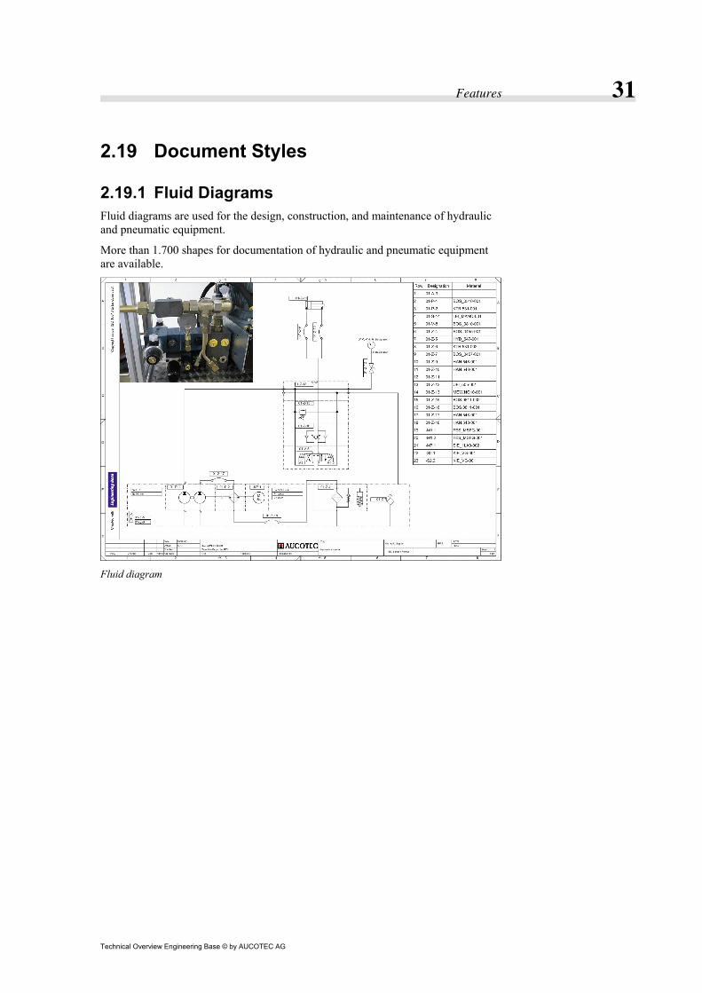
2.19.1 Fluid Diagrams Fluid diagrams are used for the design, construction, and maintenance of hydraulic and pneumatic equipment.
More than 1.700 shapes for documentation of hydraulic and pneumatic equipment are available.
Fluid diagram

Features 32
Technical Overview Engineering Base © by AUCOTEC AG
2.19.2 Circuit Diagrams Circuit diagrams are used for the design, construction, and maintenance of electrical equipment.
An extensive selection of shapes for technical documentation in various interna-tional standards is available.
Circuit diagram
2.19.3 HookUps HookUps are a combination of mechanical sketches and lists of components.
Features 33
Technical Overview Engineering Base © by AUCOTEC AG
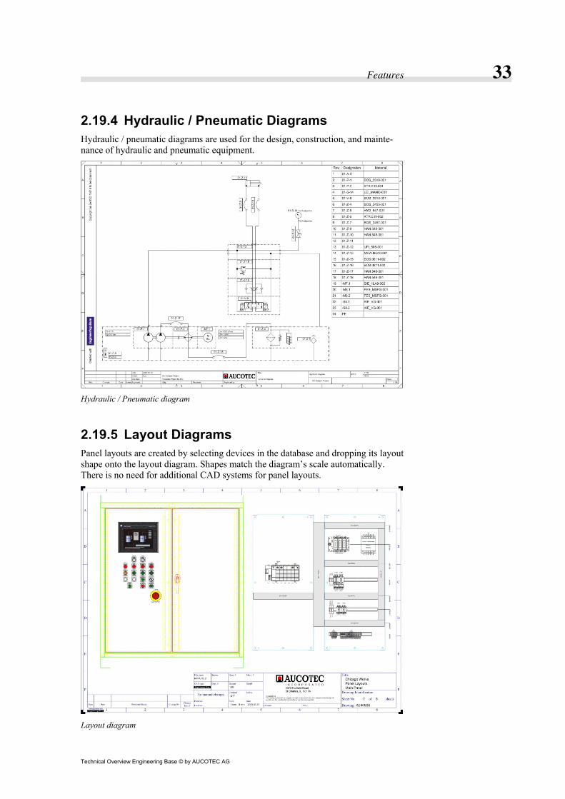
2.19.4 Hydraulic / Pneumatic Diagrams Hydraulic / pneumatic diagrams are used for the design, construction, and mainte-nance of hydraulic and pneumatic equipment.
Hydraulic / Pneumatic diagram
2.19.5 Layout Diagrams Panel layouts are created by selecting devices in the database and dropping its layout shape onto the layout diagram. Shapes match the diagram’s scale automatically. There is no need for additional CAD systems for panel layouts.
Layout diagram

Features 34
Technical Overview Engineering Base © by AUCOTEC AG
2.19.6 Logic Diagrams Logic diagrams are used to document the programming within the automation sys-tem.
Logic diagram
Features 35
Technical Overview Engineering Base © by AUCOTEC AG
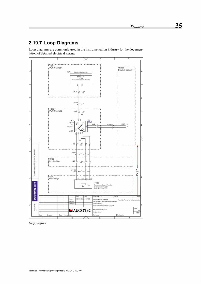
2.19.7 Loop Diagrams Loop diagrams are commonly used in the instrumentation industry for the documen-tation of detailed electrical wiring.
Loop diagram

Features 36
Technical Overview Engineering Base © by AUCOTEC AG
2.19.8 P&I Diagrams A P&I (Process and Instrumentation) diagram is a full diagrammatic representation of a process plant. Each piece of equipment is shown along with its connectivity to other equipment. It may be regarded as an enhanced process flow diagram which shows, in addition to the process itself, details such as control and instrumentation equipment, pump and pipe sizes etc. Each instrument / piece of equipment is shown by a symbol denoting its type (pump, sensor, valve etc.) and a unique identification number or tag for differentiation from others.
2.19.9 Single-Line Diagrams Single-line diagrams show components in an overview.
Single-Line diagram
2.19.10 Specification Sheets The specification sheet is commonly used in the instrumentation industry and shows detailed information about the material, and a list of the components where that ma-terial is used.

Features 37
Technical Overview Engineering Base © by AUCOTEC AG
2.19.11 Wiring Diagrams Wiring diagrams are commonly used for documentation of panel wiring.
Wiring diagram
2.19.12 Tag Sheets The tag sheet is commonly used in the instrumentation industry and shows detailed information about the material, and a list of the components where that material is used.

Features 38
Technical Overview Engineering Base © by AUCOTEC AG
2.20 Wizards and Tools
2.20.1 About Wizards and Tools If you perform a task repeatedly, you can automate this task using a macro. A macro is a series of commands and functions that are stored in a Microsoft Visual Basic module and can be run whenever you need to perform the task.
For some standard tasks, AUCOTEC has developed the following macros:
• Cable Wizard • Structure Catalog • Merge I/O Wizard • Multi Terminal Block Diagram Wizard • Quality Management Tool • Relay and Contactor Wizard • Terminal Block Wizard • Typical Select and Typical Copy • Update Dialog from Type Wizard • Update from Catalog Wizard • PLC Address Wizard • PROFIBUS Configurator • Price Calculation • Swap Labels • Dimensioning • Assign Wires to Cables Automatically • Assign Wires to Cables Manually • Special Reports for Cables and Wires • Copy Attributes from Project to Wires • Replace Text with Reference to Dictionary More macros are available for download from our web site at http://www.aucotec.com/Downloads-dl-eng-DLsViewsDL-eng-titleA-sid-59.html.
Features 39
Technical Overview Engineering Base © by AUCOTEC AG
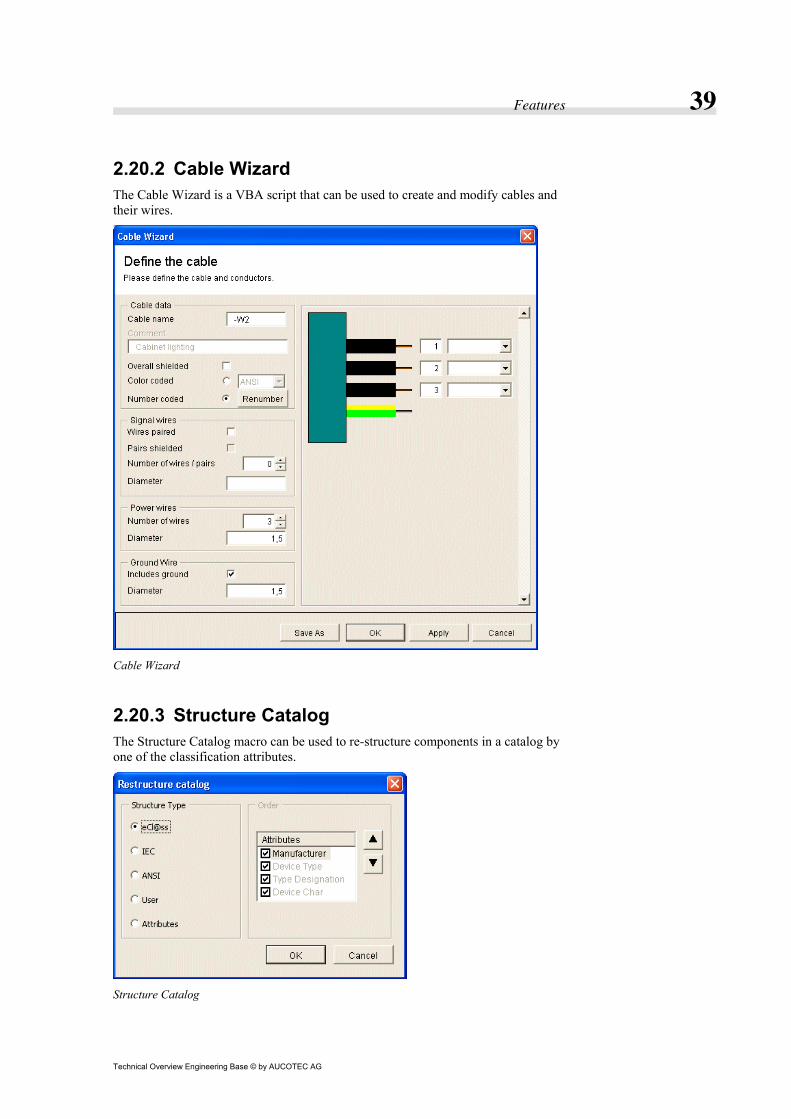
2.20.2 Cable Wizard The Cable Wizard is a VBA script that can be used to create and modify cables and their wires.
Cable Wizard
2.20.3 Structure Catalog The Structure Catalog macro can be used to re-structure components in a catalog by one of the classification attributes.
Structure Catalog
Features 40
Technical Overview Engineering Base © by AUCOTEC AG
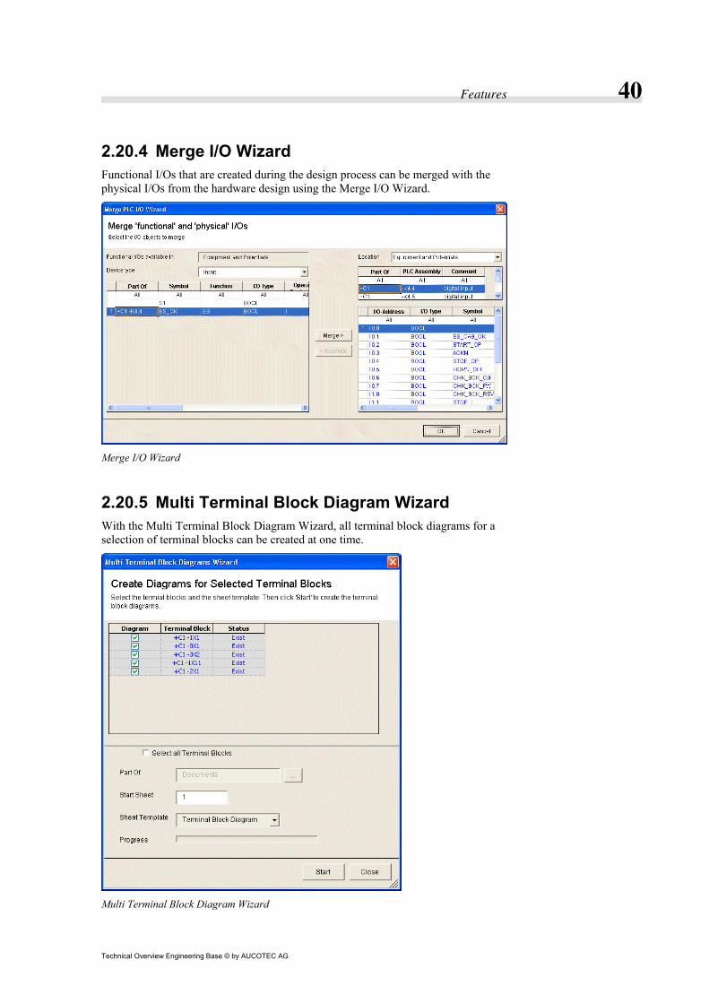
2.20.4 Merge I/O Wizard Functional I/Os that are created during the design process can be merged with the physical I/Os from the hardware design using the Merge I/O Wizard.
Merge I/O Wizard
2.20.5 Multi Terminal Block Diagram Wizard With the Multi Terminal Block Diagram Wizard, all terminal block diagrams for a selection of terminal blocks can be created at one time.
Multi Terminal Block Diagram Wizard

Features 41
Technical Overview Engineering Base © by AUCOTEC AG
2.20.6 Quality Management Tool The Quality Management Tool ensures proper application of standards to enhance the quality of your documentation. A wide number of options are available to adapt the implemented checking routines to individual requirements.
Quality Management Tool
Because the Quality Management Tool is a VBA macro, it can easily be enhanced with individual routines for specific needs.
Features 42
Technical Overview Engineering Base © by AUCOTEC AG
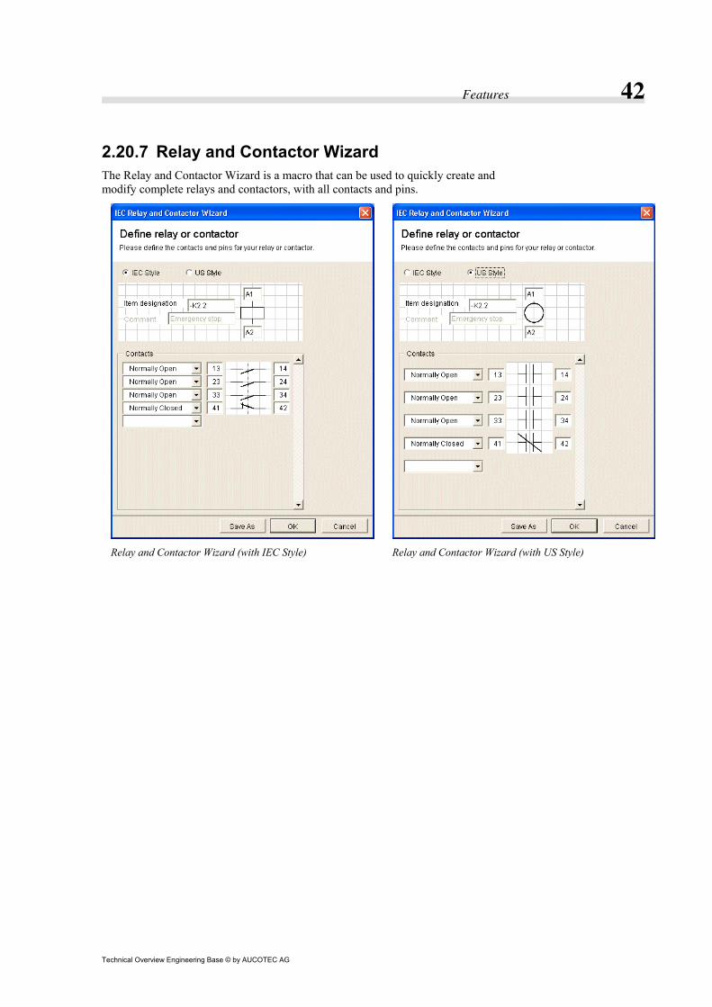
2.20.7 Relay and Contactor Wizard The Relay and Contactor Wizard is a macro that can be used to quickly create and modify complete relays and contactors, with all contacts and pins.
Relay and Contactor Wizard (with IEC Style)
Relay and Contactor Wizard (with US Style)

Features 43
Technical Overview Engineering Base © by AUCOTEC AG
2.20.8 Terminal Block Wizard The Terminal Block Wizard is a macro that can be used to create and modify termi-nal blocks with their terminals, segments (for multi-level terminals), plugs or sock-ets.
Terminal Block Wizard

Features 44
Technical Overview Engineering Base © by AUCOTEC AG
2.20.9 Typical Select and Typical Copy For each function, a typical (Function) including sheets and devices can be selected using the Typical Select macro. Then, using the Typical Copy macro, those func-tions are copied with all devices and sheets.
Typical Select Wizard
Typical Copy Wizard

Features 45
Technical Overview Engineering Base © by AUCOTEC AG
2.20.10 Update Dialog from Type Wizard The Update Dialog from Type Wizard is a macro that can be used to update the dia-logs for a selection of items within a project or catalog.
Update Dialog from Type Wizard
2.20.11 Update from Catalog Wizard The Update from Catalog Wizard is a macro that can be used to update the informa-tion for a selection of devices within a project.
Update from Catalog Wizard

Features 46
Technical Overview Engineering Base © by AUCOTEC AG
2.20.12 PLC Address Wizard The PLC Address Wizard automatically creates input and output addresses.
PLC Address Wizard

Features 47
Technical Overview Engineering Base © by AUCOTEC AG
2.20.13 PROFIBUS Configurator The PROFIBUS Configurator can be used to define the sequence for wiring devices connected to a PROFIBUS device.
PROFIBUS Configurator
2.20.14 Price Calculation The Price Calculation wizard tallies the prices of individual items to calculate a total price for the function.
2.20.15 Swap Labels Designations for devices, locations and functions can be modified from an Excel worksheet.
Swap Labels

Features 48
Technical Overview Engineering Base © by AUCOTEC AG
2.20.16 Dimensioning Devices are dimensioned using specifications from an Excel file.
2.20.17 Assign Wires to Cables Automatically Wires are automatically assigned to cables by their destinations.
2.20.18 Assign Wires to Cables Manually This wizard helps in assigning wires to cables manually.
2.20.19 Special Reports for Cables and Wires Special reports for cable and wires are created.
2.20.20 Copy Attributes from Project to Wires The content of attributes is copied from the project to the wires.
2.20.21 Replace Text with Reference to Dictionary Replace any text with text from the dictionary, to prepare documentation for use with multiple languages.
2.20.22 XLS Configurator The XLS Configurator is a solution to create complete documentation from an Excel file.
2.20.23 Import and update items Items of any kind can be imported and updated using the Import and update items macro.

Features 49
Technical Overview Engineering Base © by AUCOTEC AG
2.21 System Architecture
2.21.1 Object-Oriented Engineering Base is developed with object-oriented languages (C++, C#). Because data is stored in the Microsoft SQL Server (a relational database management sys-tem), the Engineering Base Application Server uses object-relational mapping to bridge both worlds.
The user interface provides for every item only the commands that are available for that item.
2.21.2 Three-Tier Client/Server Architecture Engineering Base is designed as a three-tier client/server architecture. In a network, individual components can be installed on different computers to reduce network traffic to a minimum. Therefore Engineering Base scales extremely well from stand-alone installations through enterprise environments.
Searching for data in a file-based system requires you to transfer complete files via the network from the file-server to the desktop computer. Thus, the desktop com-puter is performing the search request for the file. With the three-tier client/server architecture of Engineering Base, the search request is sent from the client (desktop computer) to the server and the search is performed on the server computer without transferring any files over the network. Only the result is transferred to the client and network traffic is reduced to a minimum.
Three-tier client/server architecture

Features 50
Technical Overview Engineering Base © by AUCOTEC AG
Stand-alone installation All required components with SQL Server and Microsoft Office Visio are installed on the same computer.
Stand-alone installation
Client / Server The Engineering Base application server and SQL Server are installed on a server computer. Only the Engineering Base client components and Visio are installed on the desktop computer. All users are sharing the data hosted by the server computer. The server computer also hosts the Engineering Base Application Server to reduce network traffic to a minimum.
Data can also be shared via the Internet using a VPN (Virtual Personal Network) connection.
Client/Server Installation

Features 51
Technical Overview Engineering Base © by AUCOTEC AG
Client / Application Server / SQL Server Engineering Base application server and SQL Server are installed on different com-puters.
Client / Application Server / SQL Server
2.21.3 Microsoft SQL Server All data in Engineering Base is stored in the SQL server database. SQL Server is the state of the art relational database management system meeting the highest standards of reliability and security. Engineering Base comes with a pre-configured SQL server. Multiple projects are stored in one single database and can be accessed by multiple users at the same time.
Equipment can be organized within location and function structures. Documents can be organized in drawings. All data is entered directly into the database. Any infor-mation on lists and reports is taken directly from the information that is stored in the database.
The Database Manager, a tool for easily maintaining the database, is included with Engineering Base. All important maintenance tasks can be performed with little or no additional training.

Features 52
Technical Overview Engineering Base © by AUCOTEC AG
2.21.4 Unicode Unicode is an industry standard allowing computers to consistently represent and manipulate text expressed in most of the world's writing systems. Because Engineer-ing Base fully supports Unicode fonts, all documentation can be created for most of the world's writing systems.
Unicode sample
2.21.5 Attributes and Dialogs With its open data model, Engineering Base provides unmatched flexibility. New attributes can be created at any time and added to every object. New attributes ap-pear automatically in the object's dialog box.
2.21.6 Integrated VBA Development System Engineering Base comes with Microsoft's Integrated Development Environment (IDE) for Visual Basic for Applications (VBA) to create custom solutions for auto-mating tasks, and to interconnect to other applications, such as: Microsoft Office products (e.g. Excel, Word, Access).
VBA Development System
Features 53
Technical Overview Engineering Base © by AUCOTEC AG
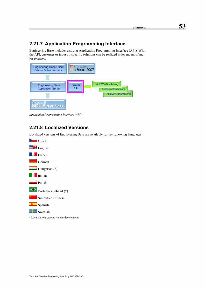
2.21.7 Application Programming Interface Engineering Base includes a strong Application Programming Interface (API). With the API, customer or industry-specific solutions can be realized independent of ma-jor releases.
Application Programming Interface (API)
2.21.8 Localized Versions Localized versions of Engineering Base are available for the following languages:
Czech
English
French
German
Hungarian (*)
Italian
Polish
Portuguese-Brazil (*)
Simplified Chinese
Spanish
Swedish (*) Localizations currently under development

Features 54
Technical Overview Engineering Base © by AUCOTEC AG
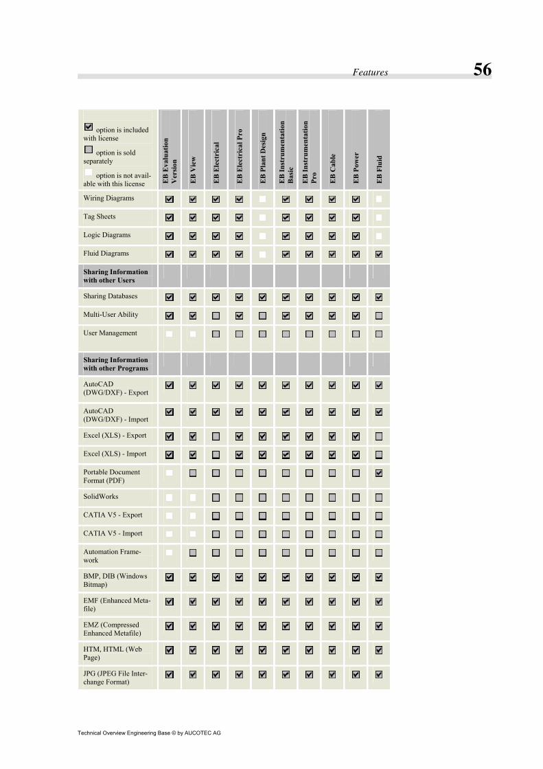
2.22 Feature Comparison Chart
option is included with license
option is sold separately
option is not avail-able with this license E
B E
valu
atio
n V
ersi
on
EB
Vie
w
EB
Ele
ctri
cal
EB
Ele
ctri
cal P
ro
EB
Pla
nt D
esig
n
EB
Inst
rum
enta
tion
Bas
ic
EB
Inst
rum
enta
tion
Pro
EB
Cab
le
EB
Pow
er
EB
Flu
id
Database Explorer
Multi-Project Access
Undo
Online Manual and Introduction
Navigating
Shortcut Menu
Catalogs
Data Service
Translate Management
Revision Management
Worksheets
Wire Routing (Fast-Wire)
Dynamic License Manager
XLS Configurator
Diagramming
Microsoft Office Visio
Drawing Borders and Title Blocks
Master-Shapes
Automatic Labeling
Real-Time Cross-References
Smart Connections
StayConnect
AutoConnect
MultiPlace
Insert Comments

Features 55
Technical Overview Engineering Base © by AUCOTEC AG
option is included with license
option is sold separately
option is not avail-able with this license E
B E
valu
atio
n V
ersi
on
EB
Vie
w
EB
Ele
ctri
cal
EB
Ele
ctri
cal P
ro
EB
Pla
nt D
esig
n
EB
Inst
rum
enta
tion
Bas
ic
EB
Inst
rum
enta
tion
Pro
EB
Cab
le
EB
Pow
er
EB
Flu
id
Insert Hyperlinks
Insert Objects
Insert Pictures
Layers
Scaling Diagrams
Printing
Multi-Window Editing
Reports
Cable Lists
Wiring Lists
Terminal Block Dia-gram
Input / Output Lists
Purchase Order Lists
Sheet Index
Fuse Lists
Kitting Lists
Overload Relay Set-tings Lists
Bill of Material
Documents Styles
Circuit Diagrams
HookUps
Hydraulic / Pneumatic Diagrams
Layout Diagrams
Loop Diagrams
P&I Diagrams
Single-Line Diagrams
Specification Sheets
Features 56
Technical Overview Engineering Base © by AUCOTEC AG
option is included with license
option is sold separately
option is not avail-able with this license E
B E
valu
atio
n V
ersi
on
EB
Vie
w
EB
Ele
ctri
cal
EB
Ele
ctri
cal P
ro
EB
Pla
nt D
esig
n
EB
Inst
rum
enta
tion
Bas
ic
EB
Inst
rum
enta
tion
Pro
EB
Cab
le
EB
Pow
er
EB
Flu
id
Wiring Diagrams
Tag Sheets
Logic Diagrams
Fluid Diagrams
Sharing Information with other Users
Sharing Databases
Multi-User Ability
User Management
Sharing Information with other Programs
AutoCAD (DWG/DXF) - Export
AutoCAD (DWG/DXF) - Import
Excel (XLS) - Export
Excel (XLS) - Import
Portable Document Format (PDF)
SolidWorks
CATIA V5 - Export
CATIA V5 - Import
Automation Frame-work
BMP, DIB (Windows Bitmap)
EMF (Enhanced Meta-file)
EMZ (Compressed Enhanced Metafile)
HTM, HTML (Web Page)
JPG (JPEG File Inter-change Format)

Features 57
Technical Overview Engineering Base © by AUCOTEC AG
option is included with license
option is sold separately
option is not avail-able with this license E
B E
valu
atio
n V
ersi
on
EB
Vie
w
EB
Ele
ctri
cal
EB
Ele
ctri
cal P
ro
EB
Pla
nt D
esig
n
EB
Inst
rum
enta
tion
Bas
ic
EB
Inst
rum
enta
tion
Pro
EB
Cab
le
EB
Pow
er
EB
Flu
id
PNG (Portable Net-work Graphics)
SVG (Scalable Vector Graphics)
SVGZ (Scalable Vec-tor Graphics - com-pressed)
TIF (Tag Image For-mat)
VSD (Visio Drawing)
WMF (Windows Metafile)
SAP Communication Framework
Siemens STEP7 SIMATIC Manager
Beckhoff TwinCAT - Export
Beckhoff TwinCAT - Import
Rockwell
Weidmüller M-Print® PRO
Zweckform
WAGO Smart De-signer - Export
WAGO Smart De-signer - Import
PHOENIX Clip Pro-ject - Export
PHOENIX Clip Pro-ject - Import
Weidmüller Rail De-signer - Export
Weidmüller Rail De-signer - Import
Insert Files
Import and update items

Features 58
Technical Overview Engineering Base © by AUCOTEC AG
option is included with license
option is sold separately
option is not avail-able with this license E
B E
valu
atio
n V
ersi
on
EB
Vie
w
EB
Ele
ctri
cal
EB
Ele
ctri
cal P
ro
EB
Pla
nt D
esig
n
EB
Inst
rum
enta
tion
Bas
ic
EB
Inst
rum
enta
tion
Pro
EB
Cab
le
EB
Pow
er
EB
Flu
id
Wizards and Tools
Cable Wizard
Structure Catalog
Merge I/O Wizard
Multi Terminal Block Diagram Wizard
Quality Management Tools
Relay and Contactor Wizard
Terminal Block Wiz-ard
Typical Select and Typical Copy
Update Dialog from Type Wizard
Update from Catalog Wizard
PLC Address Wizard
PROFIBUS Configura-tor
Price Calculation
Swap Labels
Dimensioning
Assign Wires to Cables Automatically
Assign Wires to Cables Manually
Special Reports for Cables and Wires
Copy Attributes from Project to Wires
Replace Text with Reference to Diction-ary

Features 59
Technical Overview Engineering Base © by AUCOTEC AG
option is included with license
option is sold separately
option is not avail-able with this license E
B E
valu
atio
n V
ersi
on
EB
Vie
w
EB
Ele
ctri
cal
EB
Ele
ctri
cal P
ro
EB
Pla
nt D
esig
n
EB
Inst
rum
enta
tion
Bas
ic
EB
Inst
rum
enta
tion
Pro
EB
Cab
le
EB
Pow
er
EB
Flu
id
System Architecture
Object-Oriented
Three-Tier Cli-ent/Server Architecture
Microsoft SQL Server
Unicode
Attributes and Dialogs
Integrated VBA De-velopment System
Application Program-ming Interface
Localized Versions

Licenses 60
Technical Overview Engineering Base © by AUCOTEC AG
3 Licenses 3.1 Licensing Comparison Chart
option is included with license
option is sold separately
option is not avail-able with this license E
B E
valu
atio
n V
er-
sion
EB
Vie
w
EB
Ele
ctri
cal (2
)
EB
Ele
ctri
cal P
ro (2
)
EB
Pla
nt D
esig
n
EB
Inst
rum
enta
tion
Bas
ic (2
)
EB
Inst
rum
enta
tion
Pro
(2)
EB
Cab
le
EB
Pow
er (2
)
EB
Flu
id (3
)
PDF Viewing
Automation Frame-work
SAP Communication Framework
Quality Management Tool
User Management
Data Service
Hardware Configura-tion Link
Integrated VBA De-velopment System
Multi-User Ability
Translate Management
Revision Management
Wiring Lists /
Cable Lists (1)
Worksheets (1)
Excel Interface (1)
FastWire
Dynamic License Manager (4)
XLS Configurator 1) = License is not sold separately
2) = Limited sheet licenses are available
3) = Limited to 24 sheets per project
4) = Only available in combination with Flying License

Licenses 61
Technical Overview Engineering Base © by AUCOTEC AG
Supported Diagram Formats
option is included with license
option is sold separately
option is not avail-able with this license E
B E
valu
atio
n V
ersi
on
EB
Vie
w
EB
Ele
ctri
cal (2
)
EB
Ele
ctri
cal P
ro (2
)
EB
Pla
nt D
esig
n
EB
Inst
rum
enta
tion
Bas
ic
(2)
EB
Inst
rum
enta
tion
Pro
(2)
EB
Cab
le
EB
Pow
er (2
)
EB
Flu
id (3
)
Circuit Diagrams
HookUps
Hydraulic / Pneumatic Diagrams
Layout Diagrams
Loop Diagrams
P&I Diagrams
Single-Line Diagrams
Specification Sheets
Wiring Diagrams
Logic Diagrams
Tag Sheets
Fluid Diagrams 1) = License is not sold separately
2) = Limited sheet licenses are available
3) = Limited to 24 sheets per project
4) = Only available in combination with Flying License
All licenses can be managed on the local computer or shared over a network.

Licenses 62
Technical Overview Engineering Base © by AUCOTEC AG
3.2 EB Evaluation Version The Evaluation Version of Engineering Base gives prospective or new customers 60 days to make themselves familiar with the software and the concept. Most features are available. However, the Evaluation Version is limited in the number of projects and sheets per project.
3.3 EB View EB View allows read-only access to all 'live' data in the database. The user can navigate to and view projects and catalogs with all information contained therein. Documents can be printed and exported but not modified in any way.
3.4 EB Electrical EB Electrical is the automation engineering solution for machine and industrial plant builders. It includes diagramming, panel-layout, alphanumerical editing, cable plan-ning, online terminal block diagrams, PLC-configuration, import and export filters for AutoCAD and other formats, templates and IEC and JIC/ANSI libraries.
3.5 EB Electrical Pro EB Electrical Pro is the perfect solution for automation engineering for machine and industrial plant builders. It adds worksheets, Excel import and export filters, revision management, multi-user ability and translate management to the EB license, thus making it more efficient to handle larger projects.
3.6 EB Plant Design EB Plant Design is the solution for creating P&I Diagrams and plant layouts. It sup-ports physical plant structures and functional engineering.
3.7 EB Instrumentation Basic EB Instrumentation Basic is the solution for basic design in instrumentation engi-neering.
It includes diagramming, panel-layout, alphanumerical editing, worksheets, import and export filters for AutoCAD, Excel and many other formats, templates and IEC libraries, revision management, multi-user ability and translate management.
3.8 EB Instrumentation Pro EB Instrumentation Pro is the perfect solution for basic and detail design in instru-mentation engineering.
In addition to diagramming, panel-layout, alphanumerical editing, worksheets, im-port and export filters for AutoCAD, Excel and many other formats, templates and IEC libraries, revision management, multi-user ability and translate management, it includes cable planning, online wiring, SLC-configuration and JIC/ANSI libraries.

Licenses 63
Technical Overview Engineering Base © by AUCOTEC AG
3.9 EB Cable EB Cable is the perfect solution for system engineering. It is focused on the specific requirements in harness design for vehicles and other mobile devices and includes diagramming, alphanumerical editing, worksheets, block diagrams, system diagrams and cabling diagrams.
EB Cable also includes revision management, multi-user ability, translate manage-ment, industry specific solutions for signal management, and wire and plug selec-tion. Interfaces to 3D and routing tools are optional.
3.10 EB Power EB Power is the solution for automation engineering in power generation and distri-bution.
It includes diagramming, panel-layout, alphanumerical editing, worksheets, cable planning, online terminal block diagrams, PLC-configuration, import and export filters for AutoCAD, Excel and many other formats, templates and IEC and JIC/ANSI libraries, revision management, multi-user ability and translate manage-ment.
3.11 EB Fluid EB Fluid is the perfect solution for your requirements in design of hydraulic and pneumatic systems. It comes with more than 1.700 additional shapes for the fluid industry.

Industry Solutions 64
Technical Overview Engineering Base © by AUCOTEC AG
4 Industry Solutions 4.1 Engineering and Process Control From aspirin and gasoline to sugar, products made with process engineering can no longer be dispensed with in everyday life. The highly automated manufacturing plants, which have to cope with complex processes, must meet the highest demands. Be it in the primary, chemical or manufacturing industry – for all these sectors, the engineering workflow starts with a plant concept, whether in the form of a flow chart, a general diagram or a drawing of the building. Then one normally compiles all of the information that determines the further planning process spanning several assembly sectors: process engineering, electrical and automation technology or the control system. This method of operation needs a consistent, integrated data concept permitting changes in a central location, changes that must be automatically updated in all user views.
Process control technology projects are characterized by a large amount of data. One of the foremost requirements therefore is the tabular editing option. Graphic object representations frequently evolve only in the final stage of a planning project.
This branch is distinguished by special documentation and regulations – depending on the country and sector. Flexible data structures and adaptation options for cus-tomizing data are an absolute prerequisite for plant documentation in process engi-neering. Only in this way can loops, specification and consumer sheets or data re-ports get the desired layout and the required information in any form.
• EB Plant Design is the solution for creating P&I Diagrams and plant layouts. • EB Instrumentation Basic is the solution for basic design in instrumentation
engineering. • EB Instrumentation Pro is the perfect solution for basic and detail design in in-
strumentation engineering.
4.2 Wiring Harness Development From park distance control system to spacecraft control: wherever electrical or elec-tronic components are used to team up for the realization of advanced functions, leads, cables or complex wire harnesses are employed. Be it a small vehicle or a truck, a high-tech locomotive, an ocean liner or a space lab: the current must flow safely and in an orderly fashion. The planning and manufacturing of wire harnesses involves a large number of enterprises. Therefore, models for the cooperation among suppliers, with controlled data flow, adjustment of levels of information and com-prehensive standardization are essential factors for success.
Whereas in the case of rail cars or commercial vehicles, in which the total number of individual leads is a challenge; the mass production of passenger cars requires spe-cial solutions for the extensive variety of optional equipment available. Individual vehicle documentation may make sense in the first instance, but it does not make sense in the second. In vehicle manufacturing, an ever increasing number of innova-tions are being realized by means of electrical components and electronics, with on-board supply systems (control and diagnostic) becoming more and more important for new solutions. At the same time, the quality of these systems has become a deci-sive factor in the reliability of vehicles as a whole. For passenger cars alone, due to the increasing importance of on-board electronics, the number of cable harnesses has increased fourfold since the 1990’s.
• EB Cable is the perfect solution for system engineering.
Industry Solutions 65
Technical Overview Engineering Base © by AUCOTEC AG
4.3 Power Generation and Distribution Neither our society nor commerce as a whole is conceivable or sustainable without energy supply. Be it manufacturing, administration, hospitals or private households – we are all dependent on it. And the energy market has in the last decade become more and more international. Therefore the big power and distribution companies increasingly rely on international standards.
Because of this global dependence, facilities for generating and distributing electri-cal energy are subject to particularly high quality standards. This also applies to their documentation. Always up-to-date confirmed data is indispensable for maintenance and remodeling, and a precondition for these plants to be quickly and reliably re-paired in case of an emergency. Due to the long life expectancy of these facilities, documentation meeting the highest quality standards is indispensable because con-structional changes are frequently carried out by firms that were not involved in the initial construction of the original plant.
AUCOTEC AG has for many years been the market leader in Germany for engi-neering tools used by the operating companies, and their suppliers, in the power dis-tribution industry. In Slovakia and the Czech Republic the AUCOTEC EVU module is the sole tool used.
• EB Power is the solution for automation engineering in power generation and distribution.
4.4 Industrial Plant and Machine Design Industrial plant and machine building is a key-technology that drives the economy in highly industrialized countries. Industrial plant and machine builders are among the largest industry sectors and the most important employers. Products and services of industrial plant and machine builders are highly regarded worldwide.
As one of the leading products, Engineering Base sets the benchmark for the latest generation of E-CAE programs. Due to its database orientated approach, that di-rectly connects information from diagrams with information in the database, it gives the user new freedom in his or her work. Information in the database regarding items like devices, cables, wires and functions always reflects up-to-date information on the diagrams. This keeps all documents automatically consistent and free of errors. Whenever information becomes available, it is entered from the diagram, Database Explorer or worksheet into the database. Later, information can be completed and modified at any time, thus completing the documentation for the design and docu-mentation of the complete project. From the first concept and basic information to the latest modifications and smallest details, keeping everything under control is the goal of Engineering Base products.
Integrated engineering from first drafts to commissioning and maintenance
Engineering Base makes it easier than ever for the engineer and designer to develop and design machines and industrial plants, including all documentation for commis-sioning, revisions, maintenance and calculation. This integrated solution optimizes in 7 steps all material and efforts, because it is all tied together: planning, design and sales. It allows previously unmatched efficiency in customer relations and project-ing. This is true "Concurrent Engineering".
• EB Electrical is the automation engineering solution for machine and industrial plant builders.
• EB Electrical Pro is the perfect solution for automation engineering for machine and industrial plant builders.

Industry Solutions 66
Technical Overview Engineering Base © by AUCOTEC AG
4.5 Sample Documents To view sample documents from various industries, feel free to visit our web site at www.aucotec.com and click Downloads.