attracting customers: design and construction of an
TRANSCRIPT

Page 1
Alan Kilian Spring 2014
Attracting Customers: Design and Construction of an
Inverted Pendulum Mechanical System with a Closed-loop
Control System for use at an industry trade show.

Page 2
Introduction:
This project is based on past learning as part of my job at the Logic PD Corporation.
The Logic PD Corporation works with other companies to help build products such as
home thermostats, portable medical devices and robots. As a Principal Embedded
Systems Engineer at the Logic PD Corporation, I work with Logic PD customers to
design electrical circuits and software systems to meet the needs of their products.
In order to meet new customers and generate sales, Logic PD attends several industry
conferences each year. These conferences include a large area for companies to setup a
table and demonstrate their products to potential customers. These conference “Expos”
can be very crowded with several hundred companies all attempting to get the attention
of conference attendees. Getting the attention of conference attendees can be difficult in
this noisy crowded environment. In order to help attract attention to the Logic PD booth,
the Vice President of the Sales group asked me if I could gather together some engineers
and create a mechanical system that would be visible to conference attendees and would
move in such a way to get the attention of these attendees as well as to demonstrate some
of the capabilities offered by Logic PD.
After discussing several possibilities with other engineers, we agreed that having an
Inverted Pendulum Mechanical System with a Closed-loop Control System
demonstration running in our booth would attract their attention. In addition, allowing
attendees to download an application to their Android smartphone to control the Inverted
Pendulum Mechanical System with a Closed-loop Control System would be a great
addition to the Logic PD booth.
My task was to build the Inverted Pendulum Mechanical System with a Closed-loop
Control System hardware, software and website. Another developer at Logic PD
developed the smartphone application.
The learning I intend to demonstrate is as follows:
To understand the mechanical principles and processes of an inverted pendulum
with a closed-loop control system.
To calculate theoretical estimates for the electronic components of motor power,
motor speed, encoder resolution, encoder rates and processing power required
to properly balance an inverted pendulum.
To select mechanical system components suitable for implementing an Inverted
Pendulum Mechanical System with a Closed-loop Control System.
To select electronic components suitable for implementing an Inverted Pendulum
Mechanical System with a Closed-loop Control System.
To construct an Inverted Pendulum Mechanical System.
To write software to implement a Closed-Loop Control System.

Page 3
To test and tune a working mechanical Inverted Pendulum with a Closed-Loop
Control System.
This project is informed by learning in my Depth Criteria and my Extended Studies in
Mathematics, Physics and Mechanics. The knowledge gained in the courses of
Engineering Fortran, Operating Systems and Data Communications and Distributed
Processing allowed me to write the software algorithms required to accomplish the goals
of the project. The courses I took in Mechanical Engineering: Systems Dynamics and
Control and Analog and Digital Control, as well as my Project #1 Develop a tuning guide
for PID control systems allowed me to select, write and test appropriate motion
controlling algorithms so that I was able to cause the Inverted Pendulum Mechanical
System to move in a way necessary to accomplish the goals of the project.
This project is intended as a demonstration of my skills in five specific areas:
Understand the mechanical principles and processes of an
inverted pendulum with a closed-loop control system.
An inverted pendulum is a pendulum with its center of mass located above its point of
rotation. It differs from a normal pendulum in that it is not statically stable. Any
deflection of the pendulum from perfectly vertical causes the pendulum to fall in the
direction of the disturbance until it reaches an equilibrium point where the pendulum’s
center of mass is directly below its pivot point.
Building a closed-loop control system to stabilize an inverted pendulum is a classic
problem in both dynamics and control system theory and is often used to test closed loop
control systems.
A free body diagram showing the dynamics of an inverted pendulum is as follows:
(Image courtesy of Wikipedia user Krishnavedala)

Page 4
The dynamics of an inverted pendulum are described in Modern Control Systems ninth
Edition by Richard Dorf and Robert Bishop pp135-137 and the online resource Inverted
Pendulum Analysis, Design and Implementation by Khalil Sultan (available at
http://www.engr.usask.ca/classes/EE/480/Inverted%20Pendulum.pdf)
I reviewed those references for guidance on how to design a closed-loop control system
to stabilize both the pendulum angle and the cart position, however these references are
mostly theoretical, only analyze the Single Input Single Output (SISO) system where the
angle of the pendulum is the only measured value and the force applied to the cart is the
only output of the system. My system has four inputs (the angle and rate of change of the
angle of the pendulum and the position and the rate of change of the position of the cart)
and a single output (The force applied to the cart) making it a more complicated Multi
Input Single Output (MISO) dynamic system.
Further, these references and analysis depend on knowing all system parameters such as
the transfer function of the motor controller, the transfer function of the motor, masses of
all components and estimates of friction of major components. Several of these
parameters could be determined through experiment, however, the transfer function of
the motor controller and motor would be extremely difficult for me to determine
experimentally given the limited laboratory equipment at my disposal.
In addition, implementation of this system using a small embedded microcontroller turns
the problem from one of continuous-time into one of discrete time. This introduces
additional challenges beyond my knowledge of control systems at this time.
Given the limitations in the knowledge of this system, we decided to implement a
Proportional Integral Differential (PID) controller with two measured inputs, two
calculated values from those inputs, and a single output.
We will measure the pendulum angle relative to the cart (A) and the cart position along
the track (X). We will calculate the rate of change vs. time of each of these inputs (ADot
and XDot) using the small microcontroller. Two PID control loops will be implemented
and their outputs summed to generate a control signal to the motor controller. This output
signal will be proportional to the force applied to the cart.
Given the number of successful implementations of this system referenced on the
Internet, we believed we could tune the PID coefficients to create a stable control system.
This was a significant risk to the project and could easily have resulted in a system that
was not able to perform acceptably. Any “real” project relying on the success of the
control system would not have been started without a thorough analysis of the dynamics
of the system. For a marketing system given a zero-dollar budget and given volunteer
labor, we determined this was the only way we could proceed.

Page 5
Even though we decided to build and tune the system without a complete theoretical
analysis of this system, I will summarize the process that is used to design a closed-loop
controller when all system parameters are known.
1. Create a free body diagram showing all the forces on the pendulum and cart.
2. Use the free body diagram to determine the equations of motion of the pendulum
and cart.
3. Create linear equations from the equations of motion of the pendulum and cart.
Possibly by making assumptions about maximum angle, forces or velocities.
4. Determine the transfer function of the pendulum and cart from the linearized
equations of motion. Using the Laplace transform is a common method for this
task.
5. The transfer function of the pendulum and cart can be characterized using many
stability analysis tools such as a pole-zero plot to gain insight on the necessary
features of a controller.
6. Determine the transfer function of the DC motor, pulley and belt drive mechanism
using equations of motion and electrical engineering equations.
7. Combine the transfer functions of the drive mechanism and the cart and pendulum
to create a transfer function of the complete system.
8. The open-loop (uncontrolled) transfer function can be analyzed using pole-zero,
impulse response, step response and root-locus analysis tools to determine a
suitable compensation system.
9. A compensation system can be designed using root-locus methods¸ Bode plots,
Nyquist Diagrams or Nichols Charts.
10. The complete closed-loop transfer function can be simulated using tools such as
MATLAB to vary the control parameters and verify the control system meets the
stability requirements.
11. The closed-loop control system can finally be implements on the test hardware
and additional stability tests made to verify correct performance and requirements
are met.
Calculate theoretical estimates for the electronic
components required to properly balance an inverted
pendulum:
Motor power
Motor speed
Encoder resolution
Processing speed.
Motor power and Motor speed:
A calculation of the required motor power involves an estimate of the mass of the
pendulum+cart+slide+belt combination, an estimate of the acceleration of the
pendulum+cart+slide+belt combination required to balance the pendulum, and an
Page 6
analysis of the motor output angle to cart position mechanical system. We had no
estimates for any of these parameters, so we relied on the original plotter designer’s
expertise in building a functional and successful plotter to provide sufficient motor power
to drive the pen and carriage. We will be adding additional mass to the carriage, and are
relying on the designers to have provided additional motor power above what they
required to drive the pen. This may turn out to be an incorrect assumption, and the project
may fail for this reason.
Encoder resolution:
Cart position encoder:
Once again, we will reply on the original plotter designer’s cart position
encoder design, and assume it is sufficient for our task.
Pendulum position encoder:
Knowing that human can balance an inverted pendulum, and estimating
that a human cannot determine the angle of a pendulum within 1 degree,
we estimate that any pendulum angle resolution which provides at least a 1
degree angle resolution will be sufficient for this task.
Processing speed:
We estimated the processing power required to run the Inverted Pendulum control system
by balancing a similar pendulum by hand and determined that the rate of change of
motion of the cart was approximately ¼ second. We could easily balance the pendulum
by moving the cart by hand and could even balance the pendulum when rapidly blinking
our eyes. These experiments demonstrated that using our human body simulated control
system we could balance the pendulum by sampling the inputs at less than 10 times-per-
second. We then chose to build a control system that could run the control look at ten
times that frequency so that we had sufficient processing power for unanticipated needs.
We chose an Atmel ATXMEGA 128 8-bit microprocessor. This processor will be able to
easily run two PID control loops at 100Hz.
Select mechanical system components suitable for
implementing an Inverted Pendulum Mechanical System
with a Closed-loop Control System.
The mechanical components required for this project are:
A pendulum
A pivot point for a pendulum
A cart that can support the pendulum pivot and the pendulum
A method of measuring the angle of the pendulum relative to the cart
A method of applying a force to move the cart left and right.
A method of measuring the position of the cart relative to the linear track
o Additionally, a method for detecting when the cart approaches the end
limits of the track

Page 7
General mechanical system:
We located a used 36 Inch wide Houston Instruments DMP-60 pen plotter which was
being thrown into the recycling area at a local technology company and viewed it as a
possible basic mechanical system we could use to build the inverted pendulum model.
This system is designed with steel rails holding a small sliding mechanism which holds
various colored pens and moves in 1 dimension across a sheet of paper. This mechanism
contained a DC motor with an incremental rotary position encoder, a toothed pulley and a
long toothed belt driving the cart. A video of this kind of plotter in action is available at:
http://www.youtube.com/watch?v=pMKNRkNPZIw after viewing this video, we were
confident that this mechanism could be used for the motor, pulley, belt and cart.
Pendulum selection:
The pendulum should have a low mass to reduce the vertical force on the pendulum pivot
point thus making the mechanical system of the pivot point simpler to design.
We chose a lightweight ¾ Inch square cross section wooden rod for the pendulum.
This rod was stiff, light and able to be easily mounted to the pendulum pivot.
Pivot point selection:
We determined that the pendulum could be mounted directly to the shaft of an optical
incremental encoder so that the encoder could serve as both the pivot point and the
pendulum angle sensor. This encoder has a pair of large bearings supporting the shaft and
glass encoder and it was estimated that the mass of the pendulum was very small
compared to an estimate of the maximum radial force the encoder could support.
Cart selection:
Page 8
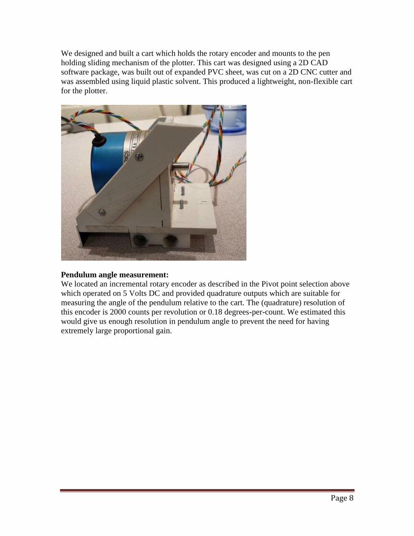
We designed and built a cart which holds the rotary encoder and mounts to the pen
holding sliding mechanism of the plotter. This cart was designed using a 2D CAD
software package, was built out of expanded PVC sheet, was cut on a 2D CNC cutter and
was assembled using liquid plastic solvent. This produced a lightweight, non-flexible cart
for the plotter.
Pendulum angle measurement:
We located an incremental rotary encoder as described in the Pivot point selection above
which operated on 5 Volts DC and provided quadrature outputs which are suitable for
measuring the angle of the pendulum relative to the cart. The (quadrature) resolution of
this encoder is 2000 counts per revolution or 0.18 degrees-per-count. We estimated this
would give us enough resolution in pendulum angle to prevent the need for having
extremely large proportional gain.

Page 9
Method for driving the cart:
The plotter contained a DC motor and rotary encoder, toothed pulley and toothed belt for
driving the pen holder along the rails, and this mechanism was reused.
Method for determining the position of the cart:

Page 10
The incremental angle position sensor attached to the DC motor provided quadrature
output signals suitable for measuring the position of the cart using the toothed belt ratio
of the speed reduction and the tooth-to-tooth distance of the drive belt.
Additional cart position measurement:
The incremental nature of the encoder on the cart positioning motor makes it impossible
to determine the absolute position of the cart when the system is powered-on, so two
additional sensors were acquired and attached to the plotter. These were short-range
infrared proximity detectors. One detector was placed at each extreme end of cart travel
and a plate on the cart reflected light back into the sensor when the cart was
approximately ¾ Inch from the absolute end of travel (the plotter hard stop). These
sensors generated a signal to the motion controller software which immediately stopped
driving the motor in the direction of travel (to prevent the cart from hitting the hard stop.)
This was used both for initializing the cart position when the system was first powered on
and well as a safety system in case the cart position was not accurate and the cart was
nearly at the end of its travel. This soft-stop is used to stop the motor drive signal and halt
the cart motion before it can cause damage to the mechanical system by hitting the end of
the rail.

Page 11
Select electronic components suitable for implementing an
Inverted Pendulum Mechanical System with a Closed-loop
Control System.
The electrical components required for this project are:
A method of running control-system software algorithms.
A method of measuring the angle of the pendulum relative to the cart.
A method of measuring the position of the cart relative to the linear track.
A method of applying an electric force to the cart position motor.
A method of sending cart position and pendulum angle measurements to an
Android application.
A method of receiving control system parameters from an Android application.
General electrical system:

Page 12
A method of running control-system software algorithms:
We estimated the processing power required to run the Inverted Pendulum control system
by balancing a similar pendulum by hand and determined that the rate of change of
motion of the cart was approximately ¼ second. We could easily balance the pendulum
by moving the cart by hand and could even balance the pendulum when rapidly blinking
our eyes. These experiments demonstrated that using our human body simulated control
system we could balance the pendulum by sampling the inputs at less than 10 times-per-
second. We then chose to build a control system that could run the control look at ten
times that frequency so that we had sufficient processing power for unanticipated needs.
We chose an Atmel ATXMEGA 128 8-bit microprocessor. This processor will be able to
easily run two PID control loops at 100Hz.
A method of measuring the angle of the pendulum relative to the cart:
The pendulum position incremental encoder requires 5 Volts DC and provides a digital
quadrature signal on a pair of wires. This interface is compatible with the ATXMEGA
128 8-bit microprocessor’s quadrature input peripherals.
A method of measuring the position of the cart relative to the linear track:
The cart position motor’s incremental encoder requires 5 Volts DC and provides a digital
quadrature signal on a pair of wires. This interface is compatible with the ATXMEGA
128 8-bit microprocessor’s quadrature input peripherals.
A method of applying an electric force to the cart position motor:
Using information from the label on the cart positioning motor, we determined the
manufacturer was Buehler, the model number was 1.13.048.501, and the motor voltage
was 24 VDC. We attempted to retrieve a data sheet on this motor, but it is no longer
manufactured, and no data is available. Using the Buehler website, we found a 24 VDC
motor with identical length, diameter and a similar part number. We made an assumption
that the specifications of this motor would be similar to the motor we had. The only
parameter we needed to know was the maximum motor current in a stall. The available
motor data sheet stated stall current of 6.5 Amps, so we needed to select a motor driver
capable of providing 24 VDC at 6.5 Amps. We chose to use a Pololu brand High-Power
Motor Driver Model 24v12 to control the DC cart positioning motor. This controller can
provide 24 Volts DC at 12 Amps continuously to brushed DC motor.
A method of sending cart position and pendulum angle measurements to an
Android application and a method of receiving control system parameters from an
Android application:
Android software applications can use the Android networking services to connect to
other devices over a network. We chose to use an Android tablet and to use the tablet’s
WiFi interface to connect to the Inverted Pendulum system. This required us to develop a
method of creating a WiFi Access point and a network endpoint capable of producing
data signals compatible with the simple ATXMEGA 128 8-bit microprocessor processor.
The processor has no networking interface, and its limited programming capacity would
not allow us to write a complex network interface for the processor. We solved this by

Page 13
adding a commercial WiFi router for home networking use and a device to translate from
an Ethernet network interface to TTL Serial UART signals which are compatible with the
ATXMEGA 128 8-bit microprocessor. The WiFi router was a common Netgear 4-port
802.11g router. The Ethernet-to-Serial converter was a Texas Instruments Stellaris
development kit RDK-S2E shown below.
The Stellaris RDK-S2E device implements a telnet networking server and a TTL Serial
UART interface. We connected the Ethernet interface to the WiFi router and the TTL
UART Serial interface to the ATXMEGA 128 8-bit microprocessor. With this
configuration, the Android application can open a networking connection and can send
and receive data from the ATXMEGA128 8-bit microprocessor’s UART connection as if
it was a network-connected device.
Construct an Inverted Pendulum Mechanical System.
The construction of the Inverted Pendulum Mechanical system was straightforward since
it was based on the already functioning pen plotter. We built an additional structure to
hold the Pendulum angle encoder as described above and we mounted all other
mechanical components underneath the plotter bed.
Write software to implement a Closed-Loop Control
System.
The software is composed of two parts:
1. Embedded firmware running on the ATXmega 128 which:
Reads the information from the Android tablet application.
Sends position and angle information to the Android tablet application.
Reads information from the angle and position sensors.
Reads switch inputs.
Runs the control loop.
Sends signals to the motor controller.
2. Android Java application running on an Android tables which:
Displays graphs showing the pendulum angle and cart position
Displays sliders so the user can select motor control coefficients.
Displays the state of the control loop as Running, Standing up and halted.

Page 14
This application was written by my colleague Tim Anderson at the Logic
PD Corporation.
The software running on the XMEGA processor is built on a set of support functions
provided by the Atmel Corporation. These functions provide services such as timers,
serial input/output, digital input/output, quadrature counting, reset processing and others.
Three additional routines were written for this project:
1. Serial port receive processing. This function reads characters from Android
application using the serial port and when a complete command is available, it
copies the values for the motor control coefficients into local variables for use by
the motor control algorithm.
2. Serial port transmit processing. This function reads local variables containing the
state of the motion control algorithm, the pendulum angle and the cart position
and sends them to the Android application for display.
3. Motor control algorithm. This is the PID controller used to balance the pendulum.

Page 15
The motor control algorithm is run 195 times-per-second. This rate is a side-effect of the
project upon which this software is based. The previous project had a 19,500 Hz
interrupt, and we simply divided the interrupt rate by 100 to get an approximately 200Hz
interrupt for the motor controller function. Given the high mass and the low accelerations
of the cart, running the control loop 200 times-per-second will make sure the control loop
runs faster than the mechanical time constant of the system and will be able to respond to
dynamic disturbances.
In normal operation, motor control algorithm reads the quadrature decoder’s output for
the pendulum angle and the cart position and computes the change in angle and the

Page 16
change in position as well as the rate of change in angle and rate of change in position.
These values are used along with the motor control coefficients to calculate a desired
force to be applied to the cart. This value is sent to the Pololu motor controller and on to
the cart drive motor which applies the force to the cart through the drive belt.
Normal operation of the Inverted Pendulum can be seen in the video located at:
http://youtu.be/MOb3ZZIolMA
Is this video, the Android tablet can be seen in the lower right of the video displaying the
cart position and pendulum angle. The motion control coefficient sliders are not visible in
this video.
Several other functions are used intermittently by the controller:
Initialization. Since all the encoders are incremental rather than absolute
encoders, when power is applied, they do not represent the actual position of the
pendulum and cart. A function detects this power-on condition and drives the cart
slowly in an open-loop mode until one of the end-of-travel switches is detected.
At this time, the location of the cart is known, and is set to an initial value. The
geometry of the pendulum and pendulum stop arms also forces the pendulum
against a hard-stop, so its position is also known, and it is initialized to this
position.
Stand-up. After initialization, the cart is at one end of travel, and the pendulum is
leaning against a hard stop at a large angle from vertical. The pendulum needs to
be placed into a vertical position for the control loop to be able to balance the
pendulum. To accomplish this, the cart is again moved slowly towards one end of
travel, and as it approaches that end of travel, the pendulum rides against a fixed
stopper arm and is forced to become more and more vertical. When the pendulum
reaches a near vertical position, this is detected and the motion control algorithm
is activated and begins balancing the pendulum.
Fall detect. When either the cart of the pendulum exceeds an acceptable position
for the motion control algorithm to be able to keep the system stable, the motion
control algorithm is halted, and the system is placed into the stand-up mode to
position the pendulum upright again.
The operation of fall detection and stand-up can be seen in the video located at:
http://youtu.be/nvfNb7JbDA0
Test and tune a working mechanical Inverted Pendulum
with a Closed-Loop Control System.
I performed a step-by-step experiment changing each control-loop coefficient and
recorded the control system performance on a previous instance of the hardware.
These experiments and my analysis are recorded in the following video clips:

Page 17
Tuning the angle feedback loop. Pure proportional gain from 10 to 250. Showing
more and more oscillatory behavior.
o Ka = 10 Kadot = 0 http://youtu.be/J_dvs1p19ik
o Ka = 50 Kadot = 0 http://youtu.be/KVUZseYmnLw
o Ka = 150 Kadot = 0 http://youtu.be/8bDfa0e-qCA
o Ka = 250 Kadot = 0 http://youtu.be/sXgoIuRVXbo
Adding damping to the angle feedback loop. Showing an increase in stability.
o Ka = 250 Kadot = 10 http://youtu.be/FAnw8e6-Obw
o Ka = 250 Kadot = 20 http://youtu.be/HT33OHBrd2o
o Ka = 250 Kadot = 40 http://youtu.be/UFaSkNSEgFo
Tuning the cart position loop. Pure proportional gain from 10 to 250. Showing
more and more oscillatory behavior.
o Kx = 3 Kxdot = 0 http://youtu.be/HJDo6fk3Yyc
o Kx = 6 Kxdot = 0 http://youtu.be/S_VHxPXBNbM
Final tuning with this system: (Using negative cart position gain as advised by Dr.
Durfee.)
o Ka = 250 Kadot = 40 Kx = -4 Kxdot = 5
http://youtu.be/ZAJfMYi3uTAhttp:/youtu.be/ZAJfMYi3uTA
When the second system was created, a tuning analysis was performed similar to the
above analysis, and we created a stable Inverted Pendulum system.
Unfortunately, the system was uninteresting as a trade show display. We then
experimented with other control loop modifications and ended up with a system we
called “Bump”. The “Bump” control system uses the PID control loop as demonstrated
above, but with the addition of a “Bump” added to the desired pendulum angle when:
The pendulum angle error exceeds a set amount.
The pendulum velocity exceeds a set amount.
This makes the control algorithm less smooth due to the step changes in desired
pendulum angle. As the pendulum position or velocity error increases, at some point, it
crosses a threshold and the desired angle is changed from zero to some angle slightly off
of zero, but still in the correct direction to maintain stability. This causes the carriage to
“Bump” out away from the center position. This made for a more interesting display, and
(barely) maintained a stable system. We concluded that the stability of a PID controller
even with the lack of a complete theoretical stability analysis is sufficient to create a
demonstration for a trade show. This feature can be seen by referring to the ABUMP and
VBUMP references in the appendix A.

Page 18
Appendix A:
Source code for the PID controller part of the firmware.
// Pin assignments for the 4 channel XMega128A3 board.
//
// cmdUART RX - PC2
// cmdUART TX - PC3
// dbgUART RX - PC6
// dbgUART TX - PC7
//
// PHA4 - PD0
// PHB4 - PD1
// IDX4 - PD2
// ENB4 - PD3
// PHA3 - PD4
// PHB3 - PD5
// IDX3 - PD6
// ENB3 - PD7
//
// PHA2 - PE0
// PHB2 - PE1
// IDX2 - PE2
// ENB2 - PE3
// PHA1 - PE4
// PHB1 - PE5
// IDX1 - PE6
// ENB1 - PE7
//
// PWM1 - PF0
// PWM2 - PF1
// PWM3 - PF2
// PWM4 - PF3
// DIR1 - PF4
// DIR2 - PF5
// DIR3 - PF6
// DIR4 - PF7
//
// PID flag - PA6
// Other flag - PA7
//
// Encoder 1 - Event channel 0, Timer TCC0
// Encoder 2 - Event channel 2, Timer TCD0
// Encoder 3 - Event channel 4, Timer TCE0
// Encoder 4 - Interrupt driven
// All PWM - Timer TCF0
//
// Periodic timer - TCE1
#include <stdio.h>
#include <string.h>
#include "avr_compiler.h"
#include "clksys_driver.h"
#include "TC_driver.h"
#include "qdec_driver.h"
#include "usart_driver.h"
#include "adc_driver.h"
#include "port_driver.h"
/*! \brief Number of lines in the quadrature encoder. */
// Note: I patched the driver to use 65535 as the period so linecount is ignored
uint8_t lineCount = 128; // 30;
volatile uint8_t flag;
volatile bool nlim;
volatile bool plim;

Page 19
int plot = 0;
/*! Define that selects the Usart used in example. */
// #define USART USARTC0
#define USART USARTC0
#define DEBUG_USART USARTC1
uint16_t read_encoder(uint16_t channel);
void set_motor_power(long val, uint16_t channel);
void setup_encoder(void);
void setup_pwm(void);
void setup_uart(void);
void setup_debug_uart(void);
void setup_periodic_timer(void);
void setup_limit_switches();
int16_t ADC_Read(ADC_CH_t *CH);
int ADC_Init( void );
void waitForPosition(unsigned int epsilon);
void home();
volatile int32_t position0, position1, potential1 = -1;
volatile double lastposition1 = 0;
volatile uint16_t previous0, previous1;
#define RX_CNT_MAX 32
volatile int rx_pnt = 0;
volatile int rx_pnt_total = 0;
char rx_buf[RX_CNT_MAX];
char rx_buf1[RX_CNT_MAX];
char cmd[RX_CNT_MAX+1];
int command_ready = 0;
void usart_debug_send_byte(uint8_t c) {
do{
// Wait until it is possible to put data into TX data register.
// NOTE: If TXDataRegister never becomes empty this will be a DEADLOCK.
}while(!USART_IsTXDataRegisterEmpty(&DEBUG_USART));
USART_PutChar(&DEBUG_USART, c);
}
#if 0
void usart_send_byte(uint8_t c) {
do{
// Wait until it is possible to put data into TX data register.
// NOTE: If TXDataRegister never becomes empty this will be a DEADLOCK.
}while(!USART_IsTXDataRegisterEmpty(&USART));
USART_PutChar(&USART, c);
}
#endif
/////////////////// START PRINTF
static int uart_putchar(char c, FILE *stream)
{
if (c == '\n') uart_putchar('\r', stream);
usart_debug_send_byte(c);
return 0;
}
static FILE mystdout = FDEV_SETUP_STREAM(uart_putchar, NULL, _FDEV_SETUP_WRITE);
#if 0
static int uart_putcharE(char c, FILE *stream)
{
if (c == '\n') uart_putcharE('\r', stream);
usart_send_byte(c);
return 0;
}
static FILE mysterr = FDEV_SETUP_STREAM(uart_putcharE, NULL, _FDEV_SETUP_WRITE);
#endif

Page 20
/////////////////// END PRINTF
volatile long time;
#if 0
ISR(USARTC0_RXC_vect)
{
uint8_t c;
c = USARTC0.DATA;
}
#endif
ISR(USARTC1_RXC_vect)
{
uint8_t c;
c = USARTC1.DATA;
//fprintf(stderr,"UART_INT [%02x] '%c'\n",c,c);
if (c == '$') {
// If '$' then reset pointer and stuff as first character
rx_pnt = 0;
// rx_buf[rx_pnt] = '$';
// rx_pnt++;
} else {
// Hypertermial only puts out carriage return for new line...
// Ignore line feed
if (c != 0x0a) {
rx_buf[rx_pnt] = c;
// Check for terminator
if (c == 0x0d) {
// Overwrite last char with NULL
rx_buf[rx_pnt]=0x00;
// Make a working copy
if(command_ready == 0) strcpy(rx_buf1, rx_buf);
rx_pnt=0;
//fprintf(stderr,"Got a CR. %d %s\n",__LINE__,rx_buf1);
command_ready = 1;
} else {
if (rx_pnt < (RX_CNT_MAX-1)) {
rx_pnt++;
rx_pnt_total++;
}
}
}
}
}
// servoMode values
#define UNHOMED 0
#define HALTED 1
#define RUNNING 2
#define HOMING 3
#define STANDINGUP 4
volatile int servoMode = UNHOMED;
char * servoModeText() {
switch(servoMode) {
case UNHOMED:
return("Unhomed");
break;
case HALTED:
return("Halted");
break;
case RUNNING:
return("Running");
break;
case HOMING:
return("Homing");
break;

Page 21
case STANDINGUP:
return("Resetting");
break;
}
return("Unknown servoMode");
}
#define PHOME 205 //230
#define HPOWER 140
unsigned int maxp = 1023;
volatile long desired0, desired1, upright;
volatile double velocity0, velocity1;
volatile double error0, error0dot;
volatile double powerX = 0;
double Xp = 0.0; //-0.4; //-0.25;
double Xd = 0.0;
double Xi = 0.0;
double error0iL = 100; // Integral limit
volatile double Ap = 20.0; //120.0; // 65
volatile double Ad = 0.0; // 20
double Ai = 0.0;
double error1iL = 100; // Integral limit
double Hp = 2.0; // HOMING porportional gain
double Hd = 0.010; // HOMING derivative gain
#define HOMELIMIT 15
double dT = 1.0/195.0; // 195 Hz PID loop time.
int side = 0;
#define ABUMP 18
#define VBUMP 20
#define VBUMP1 40
// Max velocity is around 100 = 10 ips
// To keep momentum low.
#define VMAX 80
#define VMAX1 200
// Max pendulum angle is 4.5 degrees.
#define MAXANGLE 25
#define MAXPENDERROR 200
ISR(TCE1_OVF_vect) // This is our PID controller running at 195Hz
{
int16_t delta0,delta1;
static uint16_t current0 = 0;
static uint16_t current1 = 0;
static double lastposition0 = 0;
static double lastVposition0 = 0;
static double lasterror0 = 0;
static double lasterror1 = 0;
double actual0;
static double error0i = 0;
long actual1, error1, error1dot;
static double error1i = 0;
static int toobigtimes = 0;
double epsilon0 = 10;
double epsilon1 = 5;
static uint32_t running = 0;
flag = 1;

Page 22
time++;
// Get the true linear position into position0
actual0 = read_encoder(1); // Linear
current0 = (uint32_t) actual0;
delta0 = current0 - previous0;
position0 += (int32_t) delta0;
previous0 = actual0;
if((time % 5) == 0) { // About 50 ms
velocity0 = (position0 - lastVposition0)/5.0;
lastVposition0 = position0;
}
velocity0 = (position0 - lastposition0);
if(servoMode == RUNNING){
running++;
if((running % (195 * 5)) == 0) { // About 5 seconds
if(side > 100) upright--;
if(side < -100) upright++;
fprintf(stderr,"-----> side = %d upright = %ld\n",side,upright);
side = 0;
}
} else {
running = 0;
}
error0 = desired0 - position0;
if(error0 > 0) side++;
else side--;
#if(0)
// Limit the maximum error in cart position.
if(error0 > Maxerror0) error0 = Maxerror0;
if(error0< -Maxerror0) error0 = -Maxerror0;
#endif
error0dot = (error0 - lasterror0) / dT;
// Do the integral
if(abs(error0) > epsilon0) {
error0i += (error0 * dT);
if(error0i > error0iL) error0i = error0iL;
if(error0i < -error0iL) error0i = -error0iL;
}
#if(1) // Bang-Bang controller outside deadband
// Couple error in cart position into desired pendulum angle.
desired1 = upright;
//desired1 = 0;
//if(error0 > 2000) desired1 = -1 * (ABUMP + (int)((error0-2000)/2000));
//if(error0 < -2000) desired1 = ABUMP - (int)((error0+2000)/2000);
// Let's try no proportional at all
if(error0 > 2000) desired1 = (-1 * ABUMP) + upright;
if(error0 < -2000) desired1 = ABUMP + upright;
//if(error0 > 4000) desired1 = (-1 * ABUMP * 1.5) + upright;
//if(error0 < -4000) desired1 = ( ABUMP * 1.5) + upright;
//if(error0 > 6000) desired1 = (-1 * ABUMP * 2.5) + upright;
//if(error0 < -6000) desired1 = ( ABUMP * 2.5) + upright;
//if(abs(error0) > 2000) { // Only do velocity controls outside the deadband
if(velocity0 > VMAX) desired1 = VBUMP;
if(velocity0 < -VMAX) desired1 = -VBUMP;
//if(velocity0 > VMAX1) desired1 = VBUMP1;
//if(velocity0 < -VMAX1) desired1 = -VBUMP1;
//}
#else // Proportional
#define Ke -0.007
desired1 = (int)(error0*Ke);

Page 23
if(velocity0 > VMAX) desired1 = VBUMP;
if(velocity0 < -VMAX) desired1 = -VBUMP;
#endif
// Limit the maximum pendulum angle
if(desired1 > MAXANGLE) desired1 = MAXANGLE;
if(desired1 < -MAXANGLE) desired1 = -MAXANGLE;
// Get the true pendulum angle into position1
actual1 = read_encoder(2); // Angle
current1 = (uint32_t) actual1;
delta1 = current1 - previous1;
position1 += (int32_t) delta1;
previous1 = actual1;
velocity1 = position1 - lastposition1;
error1 = desired1 - position1;
error1dot = (error1 - lasterror1) / dT;
if(servoMode == STANDINGUP){
// Watch to see if the pendulum is upright enough to start the controller
if(position0 > 0) { // We are on the right-half of the slide
if((error1 < -10) & (error1 > -20)) servoMode = RUNNING; // Start the
controller.
} else { // We are on the left-half of the slide
if((error1 > 10) & (error1 < 20)) servoMode = RUNNING; // Start the
controller.
}
} else if(servoMode == HALTED){
// Watch to see if the pendulum is upright enough to start the controller
if(abs(error1) < 20) servoMode = RUNNING; // Start the controller.
}
if((servoMode == RUNNING) && (abs(error1) > MAXPENDERROR)) {
fprintf(stderr,"-------------------toobigtimes = %d\n",toobigtimes);
if(toobigtimes++ > 3) {
toobigtimes = 0;
set_motor_power(0,1); // Stop the motor
fprintf(stderr,"Error too large. D=%ld p=%ld e=%ld\n",desired1, position1,
desired1 - position1);
fprintf(stderr,"actual1 = %ld, current1 = %ld, delta1 = %ld\nposition1 = %ld,
previous1 = %ld\n",(long)actual1, (long)current1, (long)delta1, (long)position1,
(long)previous1);
fprintf(stderr,"error1 = %ld\n",(long)error1);
desired0 = 0;
fprintf(stderr,"Delay 5 sec near 378\n");
_delay_ms(5000); // Wait for things to settle down
servoMode = STANDINGUP;
}
} else {
toobigtimes = 0;
}
if(servoMode == RUNNING) {
// Do the integral
if(abs(error1) > epsilon1) {
error1i += (error1 * dT);
if(error1i > error1iL) error1i = error1iL;
if(error1i < -error1iL) error1i = -error1iL;
}
powerX = ((double)error1 * Ap) +
((double)error1dot * Ad) +
((double)error1i * Ai) +
((double)error0 * Xp) +
((double)error0dot * Xd) +
((double)error0i * Xi);
set_motor_power((long)powerX,1);
} else if(servoMode == HOMING) {
if(error0 < 100) servoMode = STANDINGUP;

Page 24
set_motor_power(((double)error0 * Hp)+((double)error0dot * Hd) ,1); // Pure PD on
cart position
} else if(servoMode == HALTED) {
set_motor_power(0,1); // Stop the motor.
} else if(servoMode == STANDINGUP) {
if(error1 > 0) set_motor_power( HPOWER, 1); // Move right if pendulum is leaning
right
else set_motor_power(-HPOWER, 1); // Move left if pendulum is leaning
left
}
lastposition0 = position0;
lastposition1 = position1;
lasterror0 = error0;
lasterror1 = error1;
}
bool anylimithit();
bool neglimithit();
bool poslimithit();
#define MPISIZE 195*5
uint16_t mpI = 0;
uint16_t motorPower[MPISIZE];
double motorPowerAverage;
#define DMAX 10 // Maximum pendulum tilt compensation
void waitForPosition(unsigned int epsilon) {
while(abs(error0) > epsilon) {
_delay_ms(10);
}
}
void
motorPowerPrint() {
int i;
double average = 0.0;
for(i=0;i<(MPISIZE);i++) average += motorPower[i];
printf("%lf\n",average/(MPISIZE));
}
int main( void )
{
int16_t i;
char *param_pnt;
//long prints = 0;
long lasttime = 0;
long nexttime = 0;
int l;
// Configure PLL with the 2 MHz RC oscillator as source and
// multiply by 10 to get 20 MHz PLL clock and enable it. Wait
// for it to be stable.
CLKSYS_PLL_Config( OSC_PLLSRC_RC2M_gc, 10 ); // 10=20Mhz 16=32Mhz
CLKSYS_Enable( OSC_PLLEN_bm );
do {} while ( CLKSYS_IsReady( OSC_PLLRDY_bm ) == 0 );
CLKSYS_Main_ClockSource_Select( CLK_SCLKSEL_PLL_gc );
_delay_ms(100);
PORTF.DIRSET = PIN4_bm; // Motor direction bit
PORTF.DIRSET = PIN5_bm; // Motor direction bit
PORTF.DIRSET = PIN6_bm; // Motor direction bit
PORTF.DIRSET = PIN7_bm; // Motor direction bit
PORTE.DIRSET = PIN7_bm; // ENB1
PORTE.DIRSET = PIN3_bm; // ENB2
//setup_uart(); // stderr
setup_debug_uart(); // stdout to the Ethernet gadget

Page 25
_delay_ms(10);
flag = 0;
setup_encoder();
setup_pwm();
setup_limit_switches();
setup_periodic_timer();
ADC_Init();
sei();
printf("\nReady! Sleeping for 5 seconds\n");
fprintf(stderr,"\n(stderr) Ready! Sleeping for 5 seconds\n");
_delay_ms(5000);
nlim = 0; plim = 0;
time = 0;
position0 = 0;
//position1 = PHOME; // Sitting on the left (CCW) stop
previous0 = 0;
//previous1 = 0;
PORTE_OUT |= PIN7_bm; // ENB1
PORTE_OUT |= PIN3_bm; // ENB2
TCC0.CNT = 0;
TCD0.CNT = 0;
TCE0.CNT = 0;
position0 = 0;
desired0 = 0;
desired1 = 0;
upright = 0;
maxp = 500; // Limit the maximum motor power while we are homing.
home();
while (1) {
//fprintf(stderr,"L1 %d\n",__LINE__);
if (command_ready) {
//fprintf(stderr,"L2 %d\n",__LINE__);
// If buffer is not NULL, split command and parameters
if ( rx_buf1[0] ) {
//fprintf(stderr,"L%d\n",__LINE__);
cmd[0]=0x00;
rx_buf1[RX_CNT_MAX-1] = 0; // Make sure it's null-terminated.
l = strlen(rx_buf1);
//fprintf(stderr,"L%d strlen = %d\n",__LINE__, l);
if(l > RX_CNT_MAX) l = RX_CNT_MAX-1;
for (i=0; i<l; i++) {
if (rx_buf1[i] == ' ' ) {
cmd[i]=0x00;
i++;
break;
}
cmd[i] = rx_buf1[i];
cmd[i+1] = 0x00;
}
//fprintf(stderr,"L%d\n",__LINE__);
param_pnt = &rx_buf1[i];
//fprintf(stderr,"[%s] ",cmd);
//fprintf(stderr,"[%s]\n",param_pnt);
// Process the command
// cmd - contains the command field
// param_pnt - points to parameter start
//fprintf(stderr,"L%d\n",__LINE__);
if (strncmp(cmd, "a",1)==0) {
// put code here
} else if (strncmp(cmd, "b",1)==0) {
// put code here
Page 26
} else if (strncmp(cmd, "h",1)==0) {
servoMode = UNHOMED;
home();
} else if (strncmp(cmd, "r",1)==0) {
fprintf(stderr,"RESET\n");
Ap = 20;
Ad = 0;
servoMode = UNHOMED;
_delay_ms(100); // Make sure the control loop gets the state
change notice.
home();
} else if (strncmp(cmd, "f",1)==0) {
motorPowerPrint();
} else if (strncmp(cmd, "d",1)==0) {
printf("D 0,20,50,0,0,0.5\n"); // TODO fill these in.
fprintf(stderr,"D 0,20,50,0,0,2\n"); // TODO fill these in.
} else if (strncmp(cmd, "m",1)==0) {
printf("S %s 0,20,50,0,0,0.5\n",servoModeText());
} else if (strncmp(cmd, "p",1)==0) {
plot = 195*5;
} else if (strncmp(cmd, "Ap",2)==0) {
double pvalue,dvalue,sum;
char one[20];
char two[20];
char three[20];
int ret;
//dvalue = atof(param_pnt);
ret = sscanf(param_pnt,"%s %s %s",one,two,three);
if(ret == 3) {
pvalue = atof(one);
dvalue = atof(two);
sum = atof(three);
if(sum == (pvalue + dvalue)) {
//printf("Got an Angle Proportional of %lf\n",dvalue);
if((pvalue > 0) & (pvalue < 50)) Ap = pvalue;
if((dvalue >= 0) & (dvalue < 0.5)) Ad = dvalue;
fprintf(stderr,"----- Ap = %lf Ad = %lf\n",Ap,Ad);
} else {
fprintf(stderr,"BAD sum\n");
}
} else {
fprintf(stderr,"--->%s<---\n",param_pnt);
}
} else if (strncmp(cmd, "Ad",2)==0) {
double dvalue;
dvalue = atof(param_pnt);
//printf("Got an Angle Derivative of %lf\n",dvalue);
if((dvalue > 0) & (dvalue < 0.5)) Ad = dvalue;
fprintf(stderr,"----Ad = %lf\n",Ad);
}
command_ready = 0;
//fprintf(stderr,"L%d\n",__LINE__);
}
//fprintf(stderr,"L%d\n",__LINE__);
}
//fprintf(stderr,"L%d\n",__LINE__);
if((time-lasttime) > 10) {
printf("P %ld,%ld,%ld,%ld,%ld\n",
(long)position0,
(long)velocity0,
(long)desired1,
(long)position1,
(long)powerX);
#if(0)
fprintf(stderr,"P %ld,%ld,%ld,%ld,%ld\n",
(long)position0,
(long)velocity0,
(long)desired1,
(long)position1,
(long)powerX);
#endif

Page 27
lasttime = time;
nexttime = time + 19;
//fprintf(stderr,"rx = %d rx_pnt_total = %d\n",rx_pnt,rx_pnt_total);
}
_delay_ms(1);
}
}
void home() {
int p = HPOWER;
printf("Homing...\n"); // Calibrate the X position
if(poslimithit()) { // In positive limit;
printf("In positive limit. moving negative for a little bit.\n");
set_motor_power(-p,1); // Move in the positive direction for a little while.
_delay_ms(100); // Move motor for 1 second to get out of the limit
}
set_motor_power(p,1); // Move in the positive direction
while (!poslimithit()); // Wait for negative limit
printf("At positive limit\n");
set_motor_power(1,1);
fprintf(stderr,"Waiting to stop bouncing\n");
_delay_ms(5000); // Wait for the pendulum to stop bouncing off the hard-
stop
fprintf(stderr,"Zeroing angle\n");
position0 = 30350; // Home against the negative limit.
position1 = PHOME; // Sitting on the left (CCW) stop set encoder counter to
a value of PHOME
previous1 = PHOME;
TCD0.CNT = PHOME;
_delay_ms(100); // Wait for the control loop to set previous0
printf("Homed.\n");
servoMode = STANDINGUP;
}
bool anylimithit() {
// Returns 1 if either limit switch is hit
return((PORTD.IN&0x30) != 0x30);
}
bool neglimithit() {
// Returns 1 if negative limit switch is hit
return((PORTD.IN&0x20) != 0x20);
}
bool poslimithit() {
// Returns 1 if positive limit switch is hit
return((PORTD.IN&0x10) != 0x10);
}
uint16_t read_encoder(uint16_t channel) {
uint16_t ret_val;
switch (channel) {
case 1:
ret_val = TCC0.CNT;
break;
case 2:
ret_val = TCD0.CNT;
break;
case 3:
ret_val = TCE0.CNT;
break;
default:

Page 28
ret_val = 0;
}
return ret_val;
}
void set_motor_power(long val, uint16_t channel)
{
uint16_t new_val;
new_val = abs(val);
motorPower[mpI++] = new_val;
if(mpI >= MPISIZE) {
//printf("Reset mpI\n");
mpI = 0;
}
if (abs(val) > maxp) new_val = maxp; // Limit to less than 10 bits since I have a 33
Volt supply and a 24 Volt motor
//if(new_val != 0) printf("set_motor_power %d\n",new_val);
switch (channel) {
case 1:
if (val < 0) {
PORTF_OUT &= ~PIN4_bm;
if((PORTD.IN&0x20) != 0x20) new_val = 0; // In negative limit don't
move -
} else {
PORTF_OUT |= PIN4_bm;
if((PORTD.IN&0x10) != 0x10) new_val = 0; // In positive limit don't
move +
}
// Output new compare value.
TC_SetCompareA( &TCF0, new_val);
break;
case 2:
if (val < 0) {
PORTF_OUT &= ~PIN5_bm;
} else {
PORTF_OUT |= PIN5_bm;
}
TC_SetCompareB( &TCF0, new_val);
break;
case 3:
if (val < 0) {
PORTF_OUT &= ~PIN6_bm;
} else {
PORTF_OUT |= PIN6_bm;
}
TC_SetCompareC( &TCF0, new_val);
break;
case 4:
if (val < 0) {
PORTF_OUT &= ~PIN7_bm;
} else {
PORTF_OUT |= PIN7_bm;
}
TC_SetCompareD( &TCF0, new_val);
break;
default:
break;
}
}
void setup_limit_switches() {
PORT_ConfigurePins( &PORTD,
0x30, // negative and positive limit switches ACTIVE LOW.
false, //
false, //
PORT_OPC_TOTEM_gc, //
PORT_ISC_FALLING_gc //
);
PORT_SetPinsAsInput ( &PORTD, 0x30 );

Page 29
PORT_ConfigureInterrupt0 ( &PORTD, PORT_INT0LVL_MED_gc, 0x30 );
PORT_ConfigurePins( &PORTD,
0x10, // negative and positive limit switches ACTIVE LOW.
false, //
false, //
PORT_OPC_TOTEM_gc, //
PORT_ISC_FALLING_gc //
);
PORT_SetPinsAsInput ( &PORTD, 0x10 );
PORT_ConfigureInterrupt1 ( &PORTD, PORT_INT0LVL_MED_gc, 0x10 );
PMIC.CTRL |= PMIC_MEDLVLEN_bm;
}
ISR(PORTD_INT0_vect) {
if(PORTD.IN & 0x10) {
if(!(PORTF_OUT & PIN4_bm)) set_motor_power(0,1);
nlim = 1; plim = 0;
//printf("Neg interrupt\n");
}
if(PORTD.IN & 0x20) {
if(PORTF_OUT & PIN4_bm) set_motor_power(0,1);
plim = 1; nlim = 0;
//printf("Pos interrupt\n");
}
}
ISR(PORTD_INT1_vect) {
printf("Positive limit\n");
}
void setup_encoder(void) {
// Setup PORT? with pin ? as input for QDPH0, dont invert IO pins.
//
// Setup event channel ?, pin ? on PORT? as input, don't enable index.
// if index used then state 00 is set as the index reset state.
/*
* \param qPort The port to use.
* \param qPin The first input pin (QDPH0) to use (0 - 5/6).
* \param invIO True if IO pins should be inverted.
*
* \param qEvMux Which event channel to use. Only 0, 2 and 4 is available.
* \param qPinInput The pin input of QDPH0 to the EVSYS.CHMUX .
* \param useIndex True if an optional Index pin is used.
* \param qIndexState In which state the index signal will trigger.
*
* \param qTimer The timer to use for QDEC.
* \param qEventChannel The event channel to listen to.
* \param lineCount The number of lines in the quadrature encoder.
*/
// Setup TCC0 with PORTE-Pin4 as input to Event channel 0
QDEC_Total_Setup(&PORTE, // PORT_t * qPort
4, // uint8_t qPin
false, // bool invIO
0, // uint8_t qEvMux
EVSYS_CHMUX_PORTE_PIN4_gc, // EVSYS_CHMUX_t qPinInput
false, // bool useIndex
EVSYS_QDIRM_00_gc, // EVSYS_QDIRM_t qIndexState
&TCC0, // TC0_t * qTimer
TC_EVSEL_CH0_gc, // TC_EVSEL_t qEventChannel
0); // uint8_t lineCount
// Setup TCD0 with PORTE-Pin0 as input to Event channel 2
QDEC_Total_Setup(&PORTE, // PORT_t * qPort
0, // uint8_t qPin
false, // bool invIO
2, // uint8_t qEvMux
EVSYS_CHMUX_PORTE_PIN0_gc, // EVSYS_CHMUX_t qPinInput
false, // bool useIndex
EVSYS_QDIRM_00_gc, // EVSYS_QDIRM_t qIndexState

Page 30
&TCD0, // TC0_t * qTimer
TC_EVSEL_CH2_gc, // TC_EVSEL_t qEventChannel
0); // uint8_t lineCount
#if(0)
// Setup TCE0 with PORTD-Pin4 as input to Event channel 4
QDEC_Total_Setup(&PORTD, // PORT_t * qPort
4, // uint8_t qPin
false, // bool invIO
4, // uint8_t qEvMux
EVSYS_CHMUX_PORTD_PIN4_gc, // EVSYS_CHMUX_t qPinInput
false, // bool useIndex
EVSYS_QDIRM_00_gc, // EVSYS_QDIRM_t qIndexState
&TCE0, // TC0_t * qTimer
TC_EVSEL_CH4_gc, // TC_EVSEL_t qEventChannel
0); // uint8_t lineCount
#endif
}
void setup_pwm(void)
{
// Enable output on PC0.
PORTF.DIR |= 0x0f;
// Use 10 bits for the TC period
TC_SetPeriod( &TCF0, 0x03FF );
// Configure the TC for single slope mode.
TC0_ConfigWGM( &TCF0, TC_WGMODE_SS_gc );
// Enable Compare channel A,B,C,D.
TC0_EnableCCChannels( &TCF0, TC0_CCAEN_bm | TC0_CCBEN_bm | TC0_CCCEN_bm |
TC0_CCDEN_bm );
// Start timer by selecting a clock source.
TC0_ConfigClockSource( &TCF0, TC_CLKSEL_DIV1_gc ); // 19.5312 KHz
// TC0_ConfigClockSource( &TCF0, TC_CLKSEL_DIV2_gc ); // 9.7656 KHz
// TC0_ConfigClockSource( &TCF0, TC_CLKSEL_DIV4_gc ); // 4.8828 KHz
}
void setup_periodic_timer(void)
{
/* Set period/TOP value. */
TC_SetPeriod( &TCE1, 100 ); // 10=1953 100 = 195.3 1000=19.5 Hz
/* Select clock source. */
TC1_ConfigClockSource( &TCE1, TC_CLKSEL_DIV1024_gc );
/* Enable Overflow interrupt. */
TCE1.INTCTRLA = (uint8_t) TC_OVFINTLVL_HI_gc;
PMIC.CTRL |= PMIC_HILVLEN_bm;
}
#if 0
void setup_uart(void)
{
// PIN3 (TXD0) as output.
PORTC.DIRSET = PIN3_bm;
// PF2 (RXD0) as input.
PORTC.DIRCLR = PIN2_bm;
// USARTF0, 8 Data bits, No Parity, 1 Stop bit.
USARTC0.CTRLC = (uint8_t)(USART_CHSIZE_8BIT_gc | USART_PMODE_DISABLED_gc);
// See: http://www.avrfreaks.net/index.php?name=PNphpBB2&file=printview&t=66741&start=0
// Baud Rate variables
// (2067, -4) = 9600 (at 20Mhz fper)
// (1026, -4) = 19200
// (1261, -7) = 115200
uint16_t bsel = 1261;
int bscale = -7;
// Set Baud Rate
USARTC0.BAUDCTRLB = ((unsigned char)(bscale & 0x0F) << 4) | ((unsigned char)(bsel >>
8) & 0x0F);
USARTC0.BAUDCTRLA = (unsigned char)(bsel & 0xFF);
_delay_ms(10);
// Enable both RX and TX.
USARTC0.CTRLB = (uint8_t)(USART_RXEN_bm | USART_TXEN_bm);

Page 31
// Enable RXC interrupt.
USARTC0.CTRLA = (uint8_t)USART_RXCINTLVL_LO_gc;
PMIC.CTRL |= PMIC_LOLVLEN_bm;
stderr = &mysterr; //printf
}
#endif
void setup_debug_uart(void)
{
// (TXD0) as output.
PORTC.DIRSET = PIN7_bm;
// (RXD0) as input.
PORTC.DIRCLR = PIN6_bm;
// 8 Data bits, No Parity, 1 Stop bit.
USARTC1.CTRLC = (uint8_t)(USART_CHSIZE_8BIT_gc | USART_PMODE_DISABLED_gc);
// See: http://www.avrfreaks.net/index.php?name=PNphpBB2&file=printview&t=66741&start=0
// Baud Rate variables
// (2067, -4) = 9600 (at 20Mhz fper)
// (1026, -4) = 19200
// (1261, -7) = 115200
int bsel = 1261;
int bscale = -7;
// Set Baud Rate
USARTC1.BAUDCTRLB = ((unsigned char)(bscale & 0x0F) << 4) | ((unsigned char)(bsel >>
8) & 0x0F);
USARTC1.BAUDCTRLA = (unsigned char)(bsel & 0xFF);
_delay_ms(10);
// Enable both RX and TX.
USARTC1.CTRLB = (uint8_t)(USART_RXEN_bm | USART_TXEN_bm);
// Enable RXC interrupt.
USARTC1.CTRLA = (uint8_t)USART_RXCINTLVL_LO_gc;
PMIC.CTRL |= PMIC_LOLVLEN_bm;
stdout = &mystdout; //printf
}

Page 32
Appendix B:
Source code for the Android Graphical interface.
package com.logicpd.android.invertedpendulum;
import java.util.Observable;
import java.util.Observer;
import com.androidplot.xy.XYPlot;
import com.logicpd.android.invertedpendulum.Common.GainType;
import android.app.Activity;
import android.content.BroadcastReceiver;
import android.content.Context;
import android.content.Intent;
import android.content.IntentFilter;
import android.graphics.Color;
import android.os.Bundle;
import android.os.SystemClock;
import android.util.Log;
import android.view.View;
import android.view.View.OnClickListener;
import android.widget.Button;
import android.widget.LinearLayout;
import android.widget.SeekBar;
import android.widget.TextView;
import android.widget.SeekBar.OnSeekBarChangeListener;
public class InvertedPendulumActivity extends Activity
{
// Network Service
NetworkService networkService = null;
// UI Elements
private TextView proportionalGainTextView;
private TextView derivativeGainTextView;
private TextView proportionalGainValueTextView;
private TextView derivativeGainValueTextView;
private SeekBar proportionalGainSeekBar;
private SeekBar derivativeGainSeekBar;
private SeekBar linearPositionSeekBar;
private TextView statusValueTextView;
private Button resetButton;
// Graph Elements
Graph graph;
private float Fps;
private int AverageTime;
private TextView fpsTextView;
private TextView averageTimeTextView;
private class GraphUpdater implements Observer
{
Graph graph;
XYPlot xyPlot;
int FrameNumber;
long StartTime;
public GraphUpdater(Graph pendulumGraph)
{
graph = pendulumGraph;
xyPlot = (XYPlot)graph.graphView;
Reset();

Page 33
}
public void Reset(){
FrameNumber = 0;
StartTime = 0L;
Fps = 0.0f;
AverageTime = 0;
}
@Override
public void update(Observable o, Object arg)
{
if (Common.SHOW_FRAMERATE)
{
if (StartTime == 0)
{
StartTime = SystemClock.elapsedRealtime();
}
else
{
long NowTime = SystemClock.elapsedRealtime();
FrameNumber++;
long TotalTime = (NowTime - StartTime);
Fps = ((float) FrameNumber * 1000) / ((float) (TotalTime));
AverageTime = (int) (TotalTime / FrameNumber);
if ((FrameNumber & 7) == 0)
{
runOnUiThread(FPSUpdaterRunnable);
}
}
}
}
}
private GraphUpdater graphUpdater;
public Runnable FPSUpdaterRunnable = new Runnable()
{
public void run()
{
fpsTextView.setText(String.format(getString(R.string.fps) + " %3.1f", Fps));
averageTimeTextView.setText(getString(R.string.avgTime) + " " +
Integer.toString(AverageTime));
}
};
// Receiver for incoming network packet notification to update the GUI slider value
private BroadcastReceiver receiver = new BroadcastReceiver()
{
@Override
public void onReceive(Context context, Intent intent)
{
String action = intent.getAction();
if (action.equalsIgnoreCase(Common.ACTION_LINEAR_POSITION_RECEIVED))
{
int linearPosition = intent.getIntExtra(Common.EXTRA_LINEAR_POSITION, -
1);
linearPositionSeekBar.setProgress(Common.ScaleCartPosition(linearPosition));
}
else if (action.equalsIgnoreCase(Common.ACTION_STATUS_RECEIVED))
{
String status = intent.getStringExtra(Common.EXTRA_STATUS_VALUE);
if ((status != null) && (status.length() > 0))
{
statusValueTextView.setText(status);
if (status.equalsIgnoreCase("Running"))
{
statusValueTextView.setTextColor(Color.GREEN);
}

Page 34
else if
(status.equalsIgnoreCase(getString(R.string.disconnectedStatusValue)))
{
statusValueTextView.setTextColor(Color.RED);
}
else
{
statusValueTextView.setTextColor(Color.YELLOW);
}
}
}
else if (action.equalsIgnoreCase(Common.ACTION_DEFAULT_DATA_RECEIVED))
{
ResetGainSeekBarsToDefaults();
}
}
};
@Override
public void onCreate(Bundle savedInstanceState)
{
super.onCreate(savedInstanceState);
setContentView(R.layout.main);
Common.ActivityContext = this;
proportionalGainTextView = (TextView)findViewById(R.id.proportionalGainTextView);
derivativeGainTextView = (TextView)findViewById(R.id.derivativeGainTextView);
proportionalGainValueTextView =
(TextView)findViewById(R.id.proportionalGainValueTextView);
derivativeGainValueTextView =
(TextView)findViewById(R.id.derivativeGainValueTextView);
proportionalGainSeekBar = (SeekBar)findViewById(R.id.proportionalGainSeekBar);
derivativeGainSeekBar = (SeekBar)findViewById(R.id.derivativeGainSeekBar);
proportionalGainSeekBar.setMax(100);
derivativeGainSeekBar.setMax(100);
linearPositionSeekBar = (SeekBar)findViewById(R.id.linearPositionSeekBar);
statusValueTextView = (TextView)findViewById(R.id.statusValueTextView);
statusValueTextView.setTextColor(Color.RED);
resetButton = (Button)findViewById(R.id.resetButton);
resetButton.setOnClickListener(new OnClickListener()
{
public void onClick(View v)
{
Intent resetIntent = new Intent();
resetIntent.setAction(Common.ACTION_SEND_RESET);
sendBroadcast(resetIntent);
ResetGainSeekBarsToDefaults();
}
});
OnSeekBarChangeListener seekBarListener = new OnSeekBarChangeListener()
{
@Override
public void onProgressChanged(SeekBar seekBar, int progress, boolean
fromUser)
{
if (seekBar == proportionalGainSeekBar)
{
// Scale the value
double gain = ConvertSeekBarToGain(GainType.PROPORTIONAL_GAIN,
progress);

Page 35
Common.ProportionalGainActual = gain;
proportionalGainValueTextView.setText(String.format("%.2f", gain));
}
else if (seekBar == derivativeGainSeekBar)
{
double gain = ConvertSeekBarToGain(GainType.DERIVATIVE_GAIN,
progress);
Common.DerivativeGainActual = gain;
derivativeGainValueTextView.setText(String.format("%.2f", gain));
}
}
@Override
public void onStartTrackingTouch(SeekBar seekBar)
{
}
@Override
public void onStopTrackingTouch(SeekBar seekBar)
{
}
};
// Setup change listeners for seek bars
proportionalGainSeekBar.setOnSeekBarChangeListener(seekBarListener);
derivativeGainSeekBar.setOnSeekBarChangeListener(seekBarListener);
ResetGainSeekBarsToDefaults();
linearPositionSeekBar.setProgress(50);
LinearLayout rootlayout = (LinearLayout) findViewById(R.id.rootLinearLayout);
// Setup the Graph
graph = new Graph();
if (graph.graphView != null)
{
try
{
rootlayout.addView(graph.graphView);
}
catch (Exception e)
{
Log.e("InvertedPendulumActivity", "Unable to create graph", e);
}
}
fpsTextView = (TextView)findViewById(R.id.fpsTextView);
averageTimeTextView = (TextView)findViewById(R.id.averageTimeTextView);
graphUpdater = new GraphUpdater(graph);
if (!Common.SHOW_FRAMERATE)
{
fpsTextView.setText("");
averageTimeTextView.setText("");
}
}
private void ResetGainSeekBarsToDefaults()
{
// Set to default values. Try setting to min and max so it is guaranteed to
update the label at least once when we set
// it to the default. Otherwise if the value doesn't change, the callback won't
happen and the label won't be correct.
proportionalGainSeekBar.setProgress(ConvertGainToProgressBar(GainType.PROPORTIONAL_GAIN,
Common.ProportionalGainMin));

Page 36
derivativeGainSeekBar.setProgress(ConvertGainToProgressBar(GainType.DERIVATIVE_GAIN,
Common.DerivativeGainMin));
proportionalGainSeekBar.setProgress(ConvertGainToProgressBar(GainType.PROPORTIONAL_GAIN,
Common.ProportionalGainMax));
derivativeGainSeekBar.setProgress(ConvertGainToProgressBar(GainType.DERIVATIVE_GAIN,
Common.DerivativeGainMax));
proportionalGainSeekBar.setProgress(ConvertGainToProgressBar(GainType.PROPORTIONAL_GAIN,
Common.ProportionalGainDefault));
derivativeGainSeekBar.setProgress(ConvertGainToProgressBar(GainType.DERIVATIVE_GAIN,
Common.DerivativeGainDefault));
}
private int ConvertGainToProgressBar(GainType gainType, double gain)
{
int progress = 0;
if (gainType == GainType.PROPORTIONAL_GAIN)
{
progress = (int)((gain - Common.ProportionalGainMin) /
(Common.ProportionalGainMax - Common.ProportionalGainMin) * 100);
}
else if (gainType == GainType.DERIVATIVE_GAIN)
{
progress = (int)((gain - Common.DerivativeGainMin) /
(Common.DerivativeGainMax - Common.DerivativeGainMin) * 100);
}
return progress;
}
private double ConvertSeekBarToGain(GainType gainType, int progress)
{
double gain = 0;
if (gainType == GainType.PROPORTIONAL_GAIN)
{
gain = (((double)progress / 100) * (double)(Common.ProportionalGainMax -
Common.ProportionalGainMin)) + Common.ProportionalGainMin;
}
else if (gainType == GainType.DERIVATIVE_GAIN)
{
gain = (((double)progress / 100) * (double)(Common.DerivativeGainMax -
Common.DerivativeGainMin)) + Common.DerivativeGainMin;
}
return gain;
}
// Register for notification of incoming network packets when active
@Override
protected void onResume()
{
// Register the Activity for events it cares about
IntentFilter filter = new IntentFilter();
filter.addAction(Common.ACTION_LINEAR_POSITION_RECEIVED);
filter.addAction(Common.ACTION_STATUS_RECEIVED);
filter.addAction(Common.ACTION_DEFAULT_DATA_RECEIVED);
registerReceiver(receiver, filter);
// Register the graph for updates from the network service
IntentFilter graphfilter = new IntentFilter();
graphfilter.addAction(Common.ACTION_GRAPH_DATA_RECEIVED);
registerReceiver(graph.GraphBroadcastReceiver, graphfilter);
networkService = new NetworkService();
networkService.AddObserver(graphUpdater);

Page 37
graphUpdater.Reset();
super.onResume();
}
// Unregister for notification of incoming network packets when inactive
@Override
protected void onPause()
{
unregisterReceiver(receiver);
unregisterReceiver(graph.GraphBroadcastReceiver);
networkService.Stop();
networkService.RemoveObserver(graphUpdater);
super.onPause();
}
}