ats spacecraft vibration testing 09212015 - nasa of spacecraft level vibration testing scott gordon...
TRANSCRIPT

29th Aerospace Testing Seminar, October 2015
Benefits of Spacecraft Level Vibration Testing
Scott Gordon Goddard Space Flight Center, Greenbelt, MD
Dennis Kern Jet Propulsion Laboratory, California Institute of Technology, Pasadena, CA
ABSTRACT NASA-HDBK-7008 Spacecraft Level Dynamic Environments Testing discusses the approaches, benefits, dangers, and recommended practices for spacecraft level dynamic environments testing, including vibration testing. This paper discusses in additional detail the benefits and actual experiences of vibration testing spacecraft for NASA Goddard Space Flight Center (GSFC) and Jet Propulsion Laboratory (JPL) flight projects. JPL and GSFC have both similarities and differences in their spacecraft level vibration test approach: JPL uses a random vibration input and a frequency range usually starting at 5 Hz and extending to as high as 250 Hz. GSFC uses a sine sweep vibration input and a frequency range usually starting at 5 Hz and extending only to the limits of the coupled loads analysis (typically 50 to 60 Hz). However, both JPL and GSFC use force limiting to realistically notch spacecraft resonances and response (acceleration) limiting as necessary to protect spacecraft structure and hardware from exceeding design strength capabilities. Despite GSFC and JPL differences in spacecraft level vibration test approaches, both have uncovered a significant number of spacecraft design and workmanship anomalies in vibration tests. This paper will give an overview of JPL and GSFC spacecraft vibration testing approaches and provide a detailed description of spacecraft anomalies revealed. KEY WORDS: Spacecraft, Vibration, Testing, Sinusoidal, Random INTRODUCTION The system level spacecraft vibration test can be perceived as a problematic test. It is by definition the last vibration test to be run as part of the verification program. It comes late in the project flow such that the level of programmatic risk associated with a failure is much higher than that associated with testing at a component or subsystem level. It incurs a schedule cost at a time in the program when there is usually very little schedule left and when project management is looking to save cost and schedule by cutting unnecessary activities wherever possible. Not all aerospace organizations perform spacecraft level vibration testing, especially those organizations that follow the verification approach outlined in the Space and Missiles Center Standard "Test Requirements for Launch, Upper-Stage and Space Vehicles" (Ref. 1), which does not call for system level vibration testing but rather specifies a combination of modal, strength and acoustic testing to verify that the spacecraft is ready for launch.
https://ntrs.nasa.gov/search.jsp?R=20150020490 2018-05-17T19:49:05+00:00Z

29th Aerospace Testing Seminar, October 2015
However, NASA has a long history of performing spacecraft level vibration testing for payloads launched on expendable launch vehicles (ELVs). This paper will explore the reasons behind the use of spacecraft level vibration testing at NASA. The paper will define the objectives of the spacecraft level vibration test and discuss why this type of test is important in the overall verification flow. A critical concern with performing this type of vibration test is to be able to protect the hardware from unrealistic failures at a very late stage in the program while not impacting the ability of the test to screen for design issues and workmanship flaws in hardware that is sensitive to the low-frequency launch environment. This paper will examine the limitations of spacecraft level vibration testing and discuss the steps that both JPL and GSFC take to address these limitations including the ability to perform the test safely and to minimize the risk of over-test to acceptable levels. Finally, the paper will present examples to illustrate the test approach used at JPL and GSFC for performing spacecraft level vibration testing and will discuss the effectiveness of this type of test by presenting the specific anomalies that have been uncovered. By understanding the goals of a spacecraft level vibration test, the types of failures that it can uncover, and the means by which the test can be performed safely relative to preventing over-test or unrealistic test failures, it can be shown that this as a powerful test for screening the hardware for design and workmanship issues that cannot be found in any other type of test. Not uncovering these design and workmanship issues prior to launch could result in loss of the spacecraft or failure to achieve the stated mission requirements. The intent of this paper is to provide an understanding of why NASA feels that spacecraft level vibration testing is an important and beneficial test to perform as part of the verification process. SPACECRAFT VIBRATION TEST OBJECTIVES In order to understand why both JPL and Goddard endorse spacecraft level vibration testing, it is necessary to understand the objectives of the test and how this test differs from other mechanical tests performed on the spacecraft. The primary goal of the spacecraft vibration testing is to expose the as-built spacecraft in an as close to flight configuration as possible to the low-frequency dynamic launch environment and verify that the system will perform as expected after being exposed to this dynamic input. The spacecraft test input specified by launch vehicle organizations usually covers a frequency range up to roughly 100 Hz where the mechanically transmitted energy is the dominant input for driving spacecraft responses. For frequencies above 100 Hz, direct acoustic impingement typically drives the response of the spacecraft and is covered by the spacecraft level acoustic test. The spacecraft level vibration test has three main objectives. These are:
Expose the "as-built" flight spacecraft to the mechanically transmitted low-frequency launch environment to screen for workmanship and design problems
Qualify hardware that is difficult to analyze and cannot easily be tested at lower levels of assembly such as blankets, harnesses, cables, and plumbing.
Verify modes, damping and linearity at flight-like input levels

29th Aerospace Testing Seminar, October 2015
One of the main objectives of a spacecraft level vibration test is to excite components, subsystems and nonstructural hardware (cable harnesses, bellows, connectors, actuators, plumbing lines, waveguides, brackets, dampers, shades and shields, articulation/deployment mechanisms, shunt heaters, louvers, purge equipment, hinges and restraints, blankets/supports) that respond to mechanically transmitted energy below 100 Hz and whose response is not dominated by acoustic input. The spacecraft level test is important because the test is performed on the final flight configuration so it reflects the actual design and workmanship of the flight build. While most spacecraft hardware is tested at lower levels of assembly, it is not common and in many cases impossible to replicate the exact boundary conditions of the underlying spacecraft structure for component or subsystem testing. Most of these tests are performed with the hardware rigidly fixed to the shaker. As a result there can be interactions between the underlying spacecraft mounting structure and the attached component or subsystems including rotational inputs that may not be adequately captured in a single-axis hard-mounted shaker test performed at lower levels of assembly. One important aspect of the spacecraft level vibration test is to expose mechanisms and deployables that may exhibit non-linear dynamic response to the low-frequency launch environment and demonstrate that these items will operate as expected after exposure. This type of hardware includes solar arrays and deployable antennas. It can be very difficult to realistically test these items at lower levels of assembly as the interfaces typically have redundant load paths and can span large areas of the structure. The loading on sensitive actuators and mechanisms can be very dependent on the underlying stiffness of the structure to which the deployable is attached. The final importance of testing the "as-built" flight spacecraft is the ability to screen for workmanship issues related to installation of the hardware on the spacecraft. The system level vibration test allows for testing of spacecraft hardware that is difficult to test at lower levels of assembly and will be driven by the structural modes of the spacecraft. This type of hardware includes cables, harnesses, plumbing and blankets. The low-frequency, large displacement response of the spacecraft during the system level vibration test results in an enforced-deflection response of these items. These items do not typically fail due to direct dynamic inertial response, but rather the failure modes relate to insufficient strain relief, abrasion due to relative motion, separation of blanket seams, or insufficient support fixity against the enforced motion. There is no lower level test that can be performed to adequately test these types of hardware as the failure modes are caused by the large deflections of the structure driven by the low-frequency dynamic response. This type of hardware is difficult to model analytically and is usually not part of the spacecraft level finite element model. The system level vibration test is used to verify modeling assumptions regarding modal frequencies, damping, and linearity at flight-like levels of input This type of data is usually derived from modal testing, which uses very low-levels of input to excite the structure, and in some cases, to improve the quality of the modal data, non-linear behavior is removed from the test article by shimming or using bungee cords to preload joints designed to slip under load. Therefore the damping values predicted in a modal survey test can be very low as the input energy used to excite the structure does not drive flight-like displacements for energy dissipation. Testing at flight-like input levels allow for a more accurate estimation of structural damping. Damping levels taken from spacecraft vibration tests are typically much higher than those

29th Aerospace Testing Seminar, October 2015
measured during modal testing and the higher damping values can be used to reduce the response of sensitive structures based on coupled loads analysis (CLA) results. Also some structural modes, especially those modes that drive the response of on-board mechanisms, may exhibit non-linear behavior such that the frequency and amplitude of the response may change as a function of the input level. The spacecraft vibration test therefore can be used to verify the applicability of the modal survey test results to ensure that the response amplitudes and frequencies of critical modes are accurately represented in the finite element model used for the CLA to predict flight responses. In cases where the spacecraft only has a few significant modes in the vibration test frequency range and these modes are not overly complex and can be adequately excited by the base-drive test input, then the results of the spacecraft level vibration test may be used in-place of a dedicated modal survey for deriving a test correlated finite element model (FEM) for use in performing the verification CLA. Finally, the spacecraft vibration test as performed at JPL and Goddard is not intended as a strength qualification test. It is considered a dynamic environments test along with acoustic and shock testing. Strength qualification testing is performed separately and it is usually a goal that all spacecraft hardware will have been strength qualified prior to being integrated into the spacecraft level of assembly. While it is certainly possible to achieve sufficient loads, especially at critical interfaces, to strength qualify hardware during the spacecraft vibration test, it is not a desirable situation to have to demonstrate strength qualification as part of this test as you run the risk of over-testing at other locations on the spacecraft to achieve the required load level. By performing strength qualification testing separately from spacecraft vibration testing, this allows for the test to be performed safely as there is no requirement to hit a stated response level but rather the test may be limited as necessary to stay within either CLA predictions or the test verified strength capability of the structure. REASONS FOR SPACECRAFT VIBRATION TESTING The primary reason for performing a spacecraft level vibration test is to follow the “Test Like You Fly” (TLYF) philosophy in which the vibration test provides the final chance to verify that the as-built payload will perform as expected after exposure to the low-frequency launch environment. The spacecraft level vibration test along with the spacecraft level acoustic test and shock test covers the full range of expected dynamic environments that the payload will experience during launch. The spacecraft level vibration test is the only test that simulates the low/mid-frequency mechanically transmitted launch vibration environment. Acoustics tends to drive structural response above 100 Hz for most spacecraft modes. The acoustic 1/2 wavelength must be less than the smallest S/C dimension for significant excitation of non-baffled panels. At 100 Hz, this characteristic dimension is roughly 5 feet so that below 100 Hz only large surface area items such as solar arrays and antenna dishes will respond to direct acoustic input. For most launch vehicles the acoustic spectrum rolls off quickly below 100 Hz such that the input is roughly 10 dB below the peak SPL. Most primary spacecraft structure and very heavy components that attach to the spacecraft will not be excited by acoustics and will respond primarily to mechanically transmitted energy. One critical reason for running both a vibration test and an acoustic test at the spacecraft level is that each type of input excites the spacecraft structure

29th Aerospace Testing Seminar, October 2015
differently and will screen for different types of failure modes. This is illustrated by the fact that both a coupled loads analysis and separate vibro-acoustic analysis are required to develop the full set of launch loads and environments experienced by the spacecraft and the hardware mounted to it. With all spacecraft and especially with the spacecraft produced by GSFC and JPL that typically include very sensitive one-of-a-kind science instruments, there is always the concern about the impact that workmanship will have on the ability of the hardware to perform as expected. The spacecraft level vibration test is the only test that will put significant loads into both primary and secondary structure, which responds dynamically to the low-frequency launch environment. This means it is the only test that will verify the installation and workmanship of structural interfaces between the spacecraft and attached hardware. Typically all components and most subsystems are tested separately and can be considered qualified for launch based on that lower-level of assembly testing. But the spacecraft vibration test is the only test that will screen for workmanship issues related to installation of the hardware on the spacecraft. Finally, the spacecraft that are being built by JPL and GSFC are typically one-of-a-kind spacecraft with instruments and sensors that are fabricated and tested by many different organizations from aerospace contractors, international partners and University organizations. These spacecraft are not multiple copies of production hardware in which workmanship and design issues may have already been addressed in prior builds. For these types of payloads, we rely very heavily on system level testing (vibration, acoustic, and shock) to uncover design and workmanship issues which may have been missed based on testing at lower levels of assembly due to test limitations, inadequate test specification, or inadequate simulation of boundary conditions. REQUIREMENTS FOR SPACECRAFT LEVEL VIBRATION TESTING Because spacecraft level vibration testing has proven to be beneficial in uncovering design and workmanship issues for hardware that responds to the low-frequency launch environments, the practice is required under NASA standards and is called out as a requirement in the documents which define the verification approach at each respective Center. In NASA-STD_7002, Payload Test Requirements (Ref. 2), the document states "Sinusoidal sweep vibration testing shall be performed to qualify hardware for the low-frequency (less than 50 Hz) sinusoidal transients or the sustained sinusoidal environments when they are present in flight". The overall payload testing requirements matrix in NASA-STD-7002 shows Sinusoidal Sweep Vibration (5 to 50 Hz) as a required test for ELV payloads. At GSFC, the requirement for spacecraft level sine vibration testing is called out in the Goddard document entitled Rules for the Design, Development, and Operation of Flight Systems (Ref. 3) which points to the verification flow defined in the Generalized Environmental Verification Specification (GEVS) for GSFC Flight Programs and Projects (Ref. 4). GEVS calls for "sine vibration testing at the payload/spacecraft level of assembly to simulate transient and sustained periodic mission environments". JPL Rules! DocID 55833, Rev. 1, “Spacecraft System Dynamic and Static Testing” (Ref. 5), requires random or sine vibration testing at the spacecraft and large instrument level of assembly to validate with margin the capability of the spacecraft, other than primary structure, to withstand

29th Aerospace Testing Seminar, October 2015
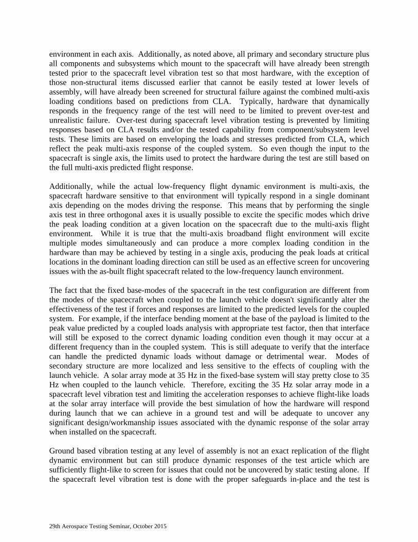
the flight vibration environment and to reveal workmanship problems in the fully assembled flight spacecraft. Most if not all current launch vehicle organizations (Delta, Atlas, Falcon, Pegasus, Ariane, etc) specify and require a spacecraft level vibration test as part of the final verification for launch. The payload planner's guide for most ELV's specify a low-frequency dynamic environment up to 100 Hz, either equivalent sine or random input, that is intended to cover the input dynamics of the low-frequency launch environment. It is required that the ELV payload test to these specified levels to demonstrate compatibility of the spacecraft with the expected low-frequency flight environment. A good example of this can be found in the Atlas V Launch Services User's Guide (AVUG) (Ref. 6), which specifies the sine environment shown in Figure 1. The AVUG requires spacecraft sine vibration testing to demonstrate compatibility with the specified sine vibration environments. Typically the test requirements for NASA ELV payloads are worked through the Launch Services Program (LSP) at the Kennedy Space Center (KSC) as part of the launch vehicle contract for a particular mission. The launch vehicle contract requires a payload level vibration test to demonstrate acceptability to fly on a given vehicle. JPL and GSFC use different approaches to spacecraft level vibration testing but both are intended to address the ELV verification requirements as specified under the launch vehicle contract and approved by KSC. With few exceptions, NASA payloads flying on ELVs are required to perform spacecraft level vibration testing prior to launch.
Figure 1. Quasi-Sinusoidal Vibration Levels for the Atlas V 400 Series and Atlas V 500 Series Based on SRS with Q=20

29th Aerospace Testing Seminar, October 2015
LIMITATIONS OF SPACECRAFT VIBRATION TESTING While there are many reasons to perform spacecraft vibration testing, it should be noted that this type of test does have limitations. Some of the limitations associated with a base-shake spacecraft level vibration test are listed below:
The test can't achieve peak flight responses at all locations on the spacecraft. Single axis swept sine or random input can't fully replicate the actual flight environment,
which excites all axes simultaneously. The fixed-base modes of the spacecraft are different from the modes of the coupled
system so the test can't accurately replicate flight-like responses. While spacecraft level vibration testing does have the above limitations, testing at the spacecraft level is still considered by NASA as beneficial for screening the hardware for workmanship and design issues prior to launch. Most of the above limitations can be addressed satisfactorily by the overall verification approach used for NASA payloads, which includes both dynamic and strength qualification testing. The remaining limitations are considered comparable to what is accepted for all base-shake tests and do not significantly detract from the primary goal of the test which is to expose the as-built flight spacecraft to the low-frequency launch environment and to find design/workmanship issues during ground test that cannot be found based on analysis or testing at lower levels of assembly. It is understood when performing a spacecraft level vibration test that it is not possible to achieve the peak response levels predicted by a CLA at all locations on the spacecraft. This is primarily because CLA predictions combine the dynamic responses of the spacecraft with loads from the appropriate steady-state thrust level for the flight event being analyzed. The steady-state loads are not replicated in the spacecraft level vibration test. Hardware that does not respond to the low-frequency launch environment will not see its full flight loading condition during the spacecraft level vibration test. The limitation that the test can't achieve peak flight responses at all locations on the spacecraft can be addressed in two ways. The first is that since this test is not intended to be a strength test, all hardware will have been strength qualified prior to integration with the spacecraft Therefore, spacecraft hardware that does not respond dynamically in the test frequency range will be adequately screened by its lower level strength qualification testing. The second is that the spacecraft vibration test is really targeted at those items that do respond dynamically in the frequency range of the test. This type of hardware is most at risk of experiencing a failure from the low-frequency launch environment and workmanship and design defects in this hardware might not be uncovered by a static strength test. Therefore, achieving the peak quasi-static predicted flight loads at all locations of the spacecraft does not have to be a goal of the spacecraft level vibration test in order to achieve the stated test objectives. In most cases, those items that do respond dynamically to the low-frequency launch environment will experience sufficiently flight-like response levels during the spacecraft test to screen for problems not uncovered by testing performed at lower levels of assembly. All single axis base-drive tests have the limitation that they do not replicate the multi-axis input from flight. These limitations are known and have been addressed over the years by performing vibration tests in each of three orthogonal axes and using conservative envelopes of the
29th Aerospace Testing Seminar, October 2015
environment in each axis. Additionally, as noted above, all primary and secondary structure plus all components and subsystems which mount to the spacecraft will have already been strength tested prior to the spacecraft level vibration test so that most hardware, with the exception of those non-structural items discussed earlier that cannot be easily tested at lower levels of assembly, will have already been screened for structural failure against the combined multi-axis loading conditions based on predictions from CLA. Typically, hardware that dynamically responds in the frequency range of the test will need to be limited to prevent over-test and unrealistic failure. Over-test during spacecraft level vibration testing is prevented by limiting responses based on CLA results and/or the tested capability from component/subsystem level tests. These limits are based on enveloping the loads and stresses predicted from CLA, which reflect the peak multi-axis response of the coupled system. So even though the input to the spacecraft is single axis, the limits used to protect the hardware during the test are still based on the full multi-axis predicted flight response. Additionally, while the actual low-frequency flight dynamic environment is multi-axis, the spacecraft hardware sensitive to that environment will typically respond in a single dominant axis depending on the modes driving the response. This means that by performing the single axis test in three orthogonal axes it is usually possible to excite the specific modes which drive the peak loading condition at a given location on the spacecraft due to the multi-axis flight environment. While it is true that the multi-axis broadband flight environment will excite multiple modes simultaneously and can produce a more complex loading condition in the hardware than may be achieved by testing in a single axis, producing the peak loads at critical locations in the dominant loading direction can still be used as an effective screen for uncovering issues with the as-built flight spacecraft related to the low-frequency launch environment. The fact that the fixed base-modes of the spacecraft in the test configuration are different from the modes of the spacecraft when coupled to the launch vehicle doesn't significantly alter the effectiveness of the test if forces and responses are limited to the predicted levels for the coupled system. For example, if the interface bending moment at the base of the payload is limited to the peak value predicted by a coupled loads analysis with appropriate test factor, then that interface will still be exposed to the correct dynamic loading condition even though it may occur at a different frequency than in the coupled system. This is still adequate to verify that the interface can handle the predicted dynamic loads without damage or detrimental wear. Modes of secondary structure are more localized and less sensitive to the effects of coupling with the launch vehicle. A solar array mode at 35 Hz in the fixed-base system will stay pretty close to 35 Hz when coupled to the launch vehicle. Therefore, exciting the 35 Hz solar array mode in a spacecraft level vibration test and limiting the acceleration responses to achieve flight-like loads at the solar array interface will provide the best simulation of how the hardware will respond during launch that we can achieve in a ground test and will be adequate to uncover any significant design/workmanship issues associated with the dynamic response of the solar array when installed on the spacecraft. Ground based vibration testing at any level of assembly is not an exact replication of the flight dynamic environment but can still produce dynamic responses of the test article which are sufficiently flight-like to screen for issues that could not be uncovered by static testing alone. If the spacecraft level vibration test is done with the proper safeguards in-place and the test is

29th Aerospace Testing Seminar, October 2015
limited such that responses do not exceed the predictions of how the coupled system will behave in flight and are kept within the demonstrated strength capability of the hardware, the test will not drive the design and the risks associated with performing the test can be adequately managed. Therefore, even with its limitations, the spacecraft level vibration test is still the best means of providing a final design/workmanship screen of the as-built flight spacecraft prior to launch. PROTECTING THE SPACECRAFT DURING VIBRATION TESTING Both JPL and GSFC strongly endorse the practice of spacecraft level vibration testing as a final screen of the "as-built" spacecraft for the low-frequency launch environment. One of the critical concerns with performing a test on the fully integrated spacecraft very late in the program flow is the risk of damage to the hardware due to inadvertent over-test. It is sometimes felt that performing a base-shake test at the spacecraft level is overly risky as an improperly run test can easily produce responses that could exceed the design capability of the hardware. One of the key reasons that JPL and GSFC endorse spacecraft vibration testing is that both organizations feel that the test can be performed without significant risk of over-test such that the benefits to performing the test in uncovering design and workmanship issues outweighs the risk of inadvertently exposing the spacecraft to unrealistic loading conditions that exceed those predicted for flight with the appropriate test margin and could possibly damage the spacecraft hardware. While GSFC and JPL agree on the need to perform spacecraft level vibration testing, each organization uses different input methods when running this type of test. JPL uses random vibration input that has been derived to approximate the sine vibration requirements from the launch vehicle, to cover mechanically transmitted energy due to vibro-acoustics in the mid-frequency range, and to provide a minimum workmanship screen for secondary structure and non-structural hardware located in spacecraft locations not responsive to acoustic excitation. JPL typically runs their random test from 5 - 200 Hz. In order to protect the spacecraft from over-test, JPL uses a force limiting approach to notch the input to limit the interface loads generated during the test. Response limiting is also performed as needed to keep component responses from exceeding design capability based on either coupled loads analysis (CLA) results or based on design loads derived from a mass acceleration curve (MAC). Goddard uses swept sine vibration as the input type for spacecraft testing. GSFC does not use the generic sine vibration environment typically found in the payload planner's guide for a particular launch vehicle. The sine vibration test levels are derived based on the interface acceleration levels from a payload specific CLA. The interface accelerations from a CLA are used to derive equivalent sine vibration input levels based on converting time history responses using an SRS/Q approach. For flight events performed as a random analysis, such as buffet, the random interface accelerations are processed using a random response spectra (RRS) approach based on Miles' equation and converted to equivalent sine by dividing by the assumed amplification factor (Q). In the case of launch vehicle events where both transient and frequency domain events are combined, the equivalent sine levels are also combined in a similar manner. In the end, the input levels are enveloped for each axis of test to derive a mission specific sine vibration spectrum. In addition to deriving mission specific sine levels, GSFC also limits interface loads and responses at critical locations to 1.25 times CLA predicted responses (for a

29th Aerospace Testing Seminar, October 2015
protoflight test) such that sine vibration test will not be a design driver for the hardware. GSFC also limits the upper frequency of the sine test to the same upper frequency of the CLA such that the test is conducted in a frequency range where there are good predictions of the coupled payload/launch vehicle response for notching the input to stay within flight predictions with the appropriate test factor. Regardless of the test approach used, both JPL and GSFC conduct the spacecraft level vibration test in such a manner as to limit the responses to the capability of the hardware based on either CLA results or on the capability demonstrated by strength testing using loads that have been derived to envelope CLA predictions. The typical spacecraft test configuration includes force gauges at the payload interface to recover loads for force limiting and sufficient response instrumentation (accelerometers and strain gauges) to be able to keep responses within safe levels for the hardware. By using a combination of force limiting and response limiting, the spacecraft level vibration test can be conducted in a safe manner such that the test should be well within the demonstrated strength capability of the hardware. JPL AND GSFC VIBRATION TEST EFFECTIVENESS Both GSFC and JPL have been performing spacecraft vibration testing as a standard practice over the last 30 plus years. Over this time, there have been a number of instances in which anomalies have been found during vibration testing which could have significantly impacted the ability of the spacecraft to achieve the goals of the mission. These anomalies were not found based on testing at lower levels of assembly and the type of failure that occurred during testing would not have been caught by static or acoustic testing alone. Only a small number of these anomalies uncovered by spacecraft level vibration testing resulted in an outright structural failure. The majority of the anomalies uncovered by this type of test involved issues related to the ability of the hardware to meet mission requirements or to perform as expected after exposure to the low-frequency launch environment. A summary of the overall test experience over the last 20 years at JPL and GSFC is shown in Table 1. It should be noted that over the test period summarized in the table, neither GSFC nor JPL has experienced damage to a spacecraft related to handling issues or an inadvertent over-test situation. Table 1. Summary of JPL and GSFC S/C Vibration Test Experience of Last 20 Years Description JPL GSFC Number of Vibration Tests Performed 17 30 Number of Significant Anomalies Uncovered 11 10 Number of Design Related Failures 5 5 Number of Workmanship Related Failures 6 5 A more detailed breakdown of the test anomalies summarized in Table 1 is shown in Tables 2 and 3.

29th Aerospace Testing Seminar, October 2015
Table 2. Workmanship Anomalies Uncovered in S/C Vibration Testing
Center Mission Anomaly Description
JPL DS1 Fasteners backed out on three assemblies
MER 1 Tank bolts incorrectly torqued
CloudSat Waveguide debonded
MSL Rover Screw backed out
GSFC GOES Missing or loose bolt caused antenna structural failure
POLAR Improper installation of a control jet
Landsat 7 Missing shims caused shock loading due to joint slip
GOES-P Missing step in build procedure. Fasteners not torqued properly
XTE HEXTE instrument frequency shift due to launch lock fabrication flaw Table 3. Design Anomalies Uncovered in S/C Vibration Testing
Center Mission Anomaly Description
JPL Cassini RTG interface electrical short DS1 Valve opened prematurely MER 1 Spacecraft fundamental frequency off by 20%. Revised VCLA model MSL DS Bolts too long, thus loosely clamped Aquarius Mono balls excessive gap
GSFC TRMM Interface gapping due to insufficient clamp band tension COBE Abrasion of instrument cover cause contamination NOAA-K IMU saturation TDRS-H Antenna modes lower than predicted. Reran VCLA GLAST LAT instrument banging due to insufficient bolt preload
A detailed description of each of the above anomalies is provided in Appendix A. SINE VIBRATION TESTING AT GSFC The Swift payload was sine vibration tested at GSFC in June, 2003. The Swift payload is shown in Figure 2. Swift launched on a Delta II 7320-10C launch vehicle on November 20, 2004. The as-tested payload weighed 3465 lbs without propellant and stood 17 feet tall including the test payload adapter fitting (PAF). The payload was vibrated in all three axes to a protoflight sine vibration level derived based on the interface acceleration levels from CLA. The interface forces and responses at critical locations were limited to keep the response levels to 1.25 times the CLA predictions. The input acceleration for one of the lateral test axes is shown in Figure 3. The as-tested level has been overlaid with the un-notched sine vibration specification derived from CLA. As can be seen from Figure 3, the input sine spec has been notched based on interface force limits at the fundamental mode of the Observatory around 8.5 Hz. Additional notches were added to keep

29th Aerospace Testing Seminar, October 2015
Figure 3. Swift Lateral Test Level (Input Specification vs Control)
0
0.1
0.2
0.3
0.4
0.5
0.6
0.7
0.8
0 10 20 30 40 50 60
Acceleration (g)
Frequency (Hz)
Spec
Cntrl
I/F Force Notch
Response Notches
responses on the spacecraft to CLA predictions times 1.25. These notches can be seen around 24, 26 and 48 Hz.
While the Swift vibration test did not uncover any significant issues or problems with the spacecraft, the test did highlight non-linear behavior with the spring-loaded door for the X-Ray Telescope (XRT). The pre/post signatures of the accelerometers located on the door showed significant differences after completion of the first lateral axis. The difference in the signature responses indicated a possible change in the XRT door due to the full level Y-axis input. The manufacturer of the door was consulted regarding the change in test data. They noted that small clearances in the hinge and latch mechanisms to allow for thermal expansion were the reason for the change in vibration signatures. Similar behavior had been noted during testing of the door at the vendor facility. Based on feedback from the door vendor, it was determined that it was safe to proceed with the remainder of the sine vibration testing. Successful post-test deployment of the door confirmed that the door survived the sine test without damage.
Figure 2. Swift Payload on Vertical Shaker at

29th Aerospace Testing Seminar, October 2015
RANDOM VIBRATION TESTING AT JPL
The Cassini flight spacecraft was random vibration tested at JPL in November 1996. The Cassini spacecraft on the shaker table for the vertical axis test is shown in Figure 4. The spacecraft as tested weighed 8,300 lbs with simulated propellant (60% volume) in the fuel tanks. The high gain antenna (HGA) was removed for this test due to test facility crane lift height limitations. The spacecraft was mounted on 8 large force transducers sandwiched between upper and lower fixture rings to measure the summed interface force. Force limiting was used to keep structural loads within 1.2 times limit loads. The Titan IV launch vehicle did not specify an interface sine or random vibration test requirement for the Cassini spacecraft. Figure 5 compares the acceleration specification for the Cassini flight spacecraft base-drive random vibration test with the launch vehicle specifications and with acceleration data from a previous flight of the Titan IV launch vehicle. The acceleration specification was originally somewhat higher (0.04 g2/Hz compared to 0.01 g2/Hz), but the specification was lowered in the 10 to 100 Hz frequency
regime after reviewing the results of an extensive FE model pre-test analysis, which indicated that excessive notching would be required with the higher level input. The flight Cassini spacecraft carried three 120 lb radioisotope thermoelectric generators (RTGs) represented by an engineering model (non-radioactive) RTG and two dynamic model RTGs for the spacecraft vibration test. Two of the three model RTGs are shown spaced 120 degrees apart mounted cantilevered on the cylindrical structure just above the conical spacecraft adapter in Figure 4. After the vibration test an electrical short between the engineering model RTG and the spacecraft structure was found. This interface problem was uncovered only in the system vibration test, in spite of extensive vibration testing of the engineering model RTG by itself. The electrical short was attributed to the vibration excitation of the engineering model RTG at a coupled spacecraft/RTG 30 Hz mode resonance. The short occurred at a response level that was well below the static load to which the unit had been designed and tested. The insulation between the RTG adapter bracket and the spacecraft was redesigned to correct this problem.
Figure 4. Cassini Spacecraft on Vertical Shaker

29th Aerospace Testing Seminar, October 2015
SUMMARY It is the consensus within the NASA ELV payload community that spacecraft level vibration testing is a necessary component of a successful verification program. Spacecraft level vibration testing provides qualification for the low to mid-frequency launch environment and is effective at screening for design and workmanship defects that would not be found by a static or acoustic test alone The spacecraft level vibration test qualifies hardware which is difficult to model and cannot be tested at lower levels of assembly and also verifies modeling assumptions of frequency and damping at flight-like input levels. Even with the limitations associated with base-shake testing, the spacecraft level vibration test can still produce responses that are sufficiently flight-like to be effective at uncovering design and workmanship issues with the as-built hardware. With the use of force and response limiting, the spacecraft vibration test can be performed safely without risk of inadvertent over-test. Both JPL and GSFC have a long history of performing spacecraft level vibration testing and over the past 20 years have used this type of test to identify issues which could have resulted in failure during launch or significantly impacted the ability of the spacecraft to meet mission requirements while on-orbit. REFERENCES 1. Air Force Space Center, "Test Requirements for Launch, Upper-Stage and Space Vehicles",
SMC-S-016 (June 2008) 2. National Aeronautics and Space Administration, "Payload Test Requirements", NASA-STD-
7002A (September 2004) 3. Goddard Space Flight Center, "Rules for the Design, Development, and Operation of Flight
Systems", GSFC-STD-1000 Rev F (August 2013) 4. Goddard Space Flight Center, "General Environmental Verification Standard (GEVS)",
GSFC-STD-7000A (April 2013) 5. Jet Propulsion Laboratory, "Spacecraft System Static and Dynamic Testing", JPL Rules!
DocID 55833, Rev. 1 (April 2013)
Figure 5. Cassini Spacecraft Random Vibration Test Level vs Launch Environments
29th Aerospace Testing Seminar, October 2015
6. United Launch Alliance, "Atlas V Launch Services Users Guide", AVUG Revision 11 (May 2010)
BIOGRAPHIES Scott Gordon holds a BS degree in Mechanical Engineering and an MS degree in Aerospace Engineering from the University of Maryland. Mr. Gordon joined the Goddard Space Flight Center in 1984 and has over 25 years of experience in the fields of structural dynamics and launch vehicle environments. Mr. Gordon is currently the Chief Engineer of the Structural Analysis Branch (Code 542) at the Goddard Space Flight Center. Prior to becoming Chief Engineer, he served in the role of lead analyst for several Goddard missions. As a technical expert in the areas of vibration and dynamic testing, Mr. Gordon has supported most major spacecraft test programs for Goddard missions since 1994. During his career at Goddard, Mr. Gordon has also participated in numerous Goddard programs involving other NASA Centers, aerospace contractors, and international partners. Dennis Kern holds B.S. and M.S. degrees in Mechanical Engineering from Cal State University at Long Beach. He has worked in the field of vibration, acoustic and shock prediction and testing for aerospace structures and components for 44 years. Mr. Kern has worked at the Jet Propulsion Laboratory since 1978 where, until recently, he was Dynamics Environments group supervisor. He is currently a principal engineer in the group. Mr. Kern has supported most of the JPL flight projects since 1978 and has led a number of technology development programs. He has played a major role in the development of several NASA and industry standards and handbooks and organized the annual NASA/USAF/Industry Spacecraft and Launch Vehicle Dynamics Environments Workshops between 1988 and 2012. Mr. Kern was awarded the NASA Exceptional Engineering Achievement Medal in 2009.

29th Aerospace Testing Seminar, October 2015
APPENDIX A: Detailed Descriptions of Spacecraft Vibration Test Anomalies JPL Test Anomalies
• Cassini: Experienced an RTG electrical short to its spacecraft mount in system random vibration test – vibration wore isolation coating off of spacecraft mount. Significant degradation in spacecraft electrical power could have resulted. Spacecraft mount was redesigned.
• Deep Space 1: Experienced several workmanship problems during system random vibration test - a hydrazine liquid service valve opened prematurely, the Spherical Langmuir Probe fell off the bottom of the Remote Sensing Unit, two screws in the Star Reference Unit fell out and another backed out part way, and fasteners loosened in the Star Tracker bracket leaving chatter marks on the shear panel. Any one of these problems might have seriously degraded the mission.
• MER 1: Fundamental modes of the spacecraft in the random vibration test were 20% greater than predicted in all three axes. FE model was updated just in time for the verification CLA cycle. Vibration test also revealed improper torque of bolts on some tanks in low-level runs. Bolts were properly torqued and test completed successfully.
• CloudSat: Cloud Profiling Radar waveguide failure in spacecraft random vibration test due to apparent poor workmanship of adhesive bonding. Possible loss of science data averted.
• MSL Rover: A soft short identified in the RA Turret Actuator Encoder during Rover thermal vacuum testing was traced to a backed out screw and washer. An investigation concluded that solithane had not been applied to the screw and it backed out during Rover vibration testing. The issue was unlikely to have otherwise been found before launch, which could have been a serious threat to the mission.
• MSL Descent Stage: A problem was identified by the extreme chatter measured by accelerometers near the RCS Thruster bolts in the Descent Stage vibration test. Inspection after the test revealed washers on the thruster bolts were loose. Torque was correct but clamping load was too low - bolts were too long for their holes. Affected bolts were replaced with shorter bolts.
• Aquarius: Instrument level random vibration test revealed serious design issues with mono-ball bipods/instrument interfaces. Looseness of mono-ball design created chattering with significant impacting spikes and high modal nonlinearity. Mono-balls were replaced with better quality.
GSFC Test Anomalies
• TRMM. During Observatory sine testing, found that the NASDA supplied PAF clamp band had insufficient tension and gapped during the test. As a result, the clamp band tension was increased for flight.
• COBE had a design problem involving abrasion of an instrument cover that created particulate contamination in the key DMR instrument. It was detected in a lateral axis sine test. This would not have been detected by any other test and would have seriously degraded the mission if not detected and fixed.
• GOES had a workmanship problem involving a missing or loose bolt that caused structural failure of a mission-critical antenna. It was detected during the lateral sine test.

29th Aerospace Testing Seminar, October 2015
• POLAR had a workmanship problem involving improper installation of a spacecraft control jet. Misalignment caused by the longitudinal axis sine vibration test would have seriously degraded the mission if it had not been detected.
• NOAA-K experienced IMU saturation during sine sweep testing. Because the spacecraft IMU provides guidance information for the Titan II launch vehicle during ascent, IMU saturation during launch would have resulted in a mission failure. Changes were made and launch vehicle restraints were implemented to resolve the problem, including wind restrictions at launch and a commanded first stage shutdown vs. fuel depletion.
• Landsat 7. During the sine vibration in a lateral axis, it was discovered that there was excessive motion of the upper truss structure resulting in shock loading on the instrument platform. The magnitude of the shock loading was analyzed and considered unacceptable for the ETM+ instrument (an instrument mass simulator was in place for the test). A review of the design based on the Landsat 6 spacecraft indicated that the original configuration included shims to take out the tolerances in the lug and clevis fittings at the end of each of the struts. A change in bolt preload was implemented and verified by offline testing to eliminate the shock loading.
• TDRS-H. During the sine vibration test, the first two modes for the Space Ground Link antenna (SGL) were lower than predicted by the model. The first mode dropped from 15 Hz to 11 Hz and the second mode dropped from 33 Hz to 25 Hz. It turned out that the mathematical model of this “simple” antenna was wrong and therefore the Verification Loads Cycle had to be rerun.
• GOES-P (third in the N-P series). After completion of a lateral axis sine test, the pre/post signature showed a frequency shift of 6%. This was greater than had previously been experienced on the GOES-N and O spacecraft during sine testing. The cause of the frequency shift was traced to a series of 14 loose bolts on the lower bus structure that served as a shear tie for the primary load path. It was determined that the when the spacecraft build was moved to a different facility, the step in the build procedure in which these fasteners were preloaded had been left out. As a result of this, the primary load path for the spacecraft had been compromised.
• The XTE HEXTE Instrument Sine Vibration Test detected that the Launch Lock Assembly of the Instrument did not have the same boundary conditions as represented in its Finite Element Model. The structural signatures of the Instrument primary modes had shifted and did not meet the success criteria following the Sine Vibration Test Program. This was caused by a weak design and a flaw in fabrication of the launch lock interface.
• The GLAST LAT instrument Sine Vibration testing detected that the instrument slipped and banged at its bolted flexure interface due to insufficient bolt preload. As a result, the bolt preload was increased at this critical interface.