noise and vibration of spacecraft structures · pdf filevehicle stages separate, cause...
TRANSCRIPT
Arenas et al.: Noise and vibration of spacecraft structures
Ingeniare. Revista chilena de ingeniería, vol. 14 Nº 3, 2006 251
Ingeniare. Revista chilena de ingeniería, vol. 14 Nº 3, 2006, pp. 251-264
NOISE AND VIBRATION OF SPACECRAFT STRUCTURES
RUIDO Y VIBRACIÓN DE ESTRUCTURAS DE VEHÍCULOS ESPACIALES
Jorge P. Arenas 1 Ravi N. Margasahayam2
Recibido 5 de agosto de 2005, aceptado el 11 de septiembre de 2006
Received: August 5, 2005 Accepted: September 11, 2006
RESUMEN
El lanzamiento de los vehículos espaciales genera condiciones extremas, tales como de vibración y acústica, que pueden
afectar la torre de lanzamiento, los vehículos espaciales y sus cargas. El ruido en el despegue y durante los dos minutos de
ascenso y fase transónica causa intensas cargas acústicas. Estas cargas acústicas son el resultado del intenso medio ambiente
acústico generado por la interacción del chorro de salida del motor del cohete y su mezcla con la atmósfera. Los choques
pirotécnicos, que ocurren cuando las etapas de un vehículo espacial se separan, causan problemas adicionales de vibración.
En este artículo se presenta una revisión de los principales aspectos relacionados con los problemas de ruido y vibración
vividos por las estructuras de las naves espaciales. La mayoría de la información está basada en las experiencias con
el trasbordador espacial en el Centro Espacial John F. Kennedy (KSC), de la NASA. Además, se presenta una revisión
de la investigación en vibroacústica realizada en el KSC. Estos programas de investigación apuntan a diseñar futuras
instalaciones de lanzamiento de naves espaciales, en donde los costos y el ruido de los cohetes durante el despegue sean
reducidos significativamente.
Palabras clave: Ruido y vibración de cohetes, fatiga estructural, trasbordador espacial, vibroacústica.
ABSTRACT
The launch of space craft generates extreme conditions, such as vibrations and acoustics that can affect the launch
pad, space craft, and their payloads. The noise at launch and during the two-minute liftoff and transonic climb phase
causes intense acoustic loads. These acoustic loads are the result of an intense acoustic environment generated by the
interaction of the rocket-engine exhaust stream mixing with the atmosphere. Pyroshocks, that occur when spacecraft
vehicle stages separate, cause additional vibration problems. In this article, an overview of the main aspects related to
noise and vibration problems experienced by spacecraft structures is presented. Most of the information is based on the
Space Shuttle experiences at the NASA’s John F. Kennedy Space Center (KSC). In addition, a review of the vibroacoustic
research being conducted at KSC is presented. These research programs are aimed at designing future space launch
facilities, where cost and rocket exhaust launch noise are significantly reduced.
Keywords: Rocket noise and vibration, structural fatigue, space shuttle, vibroacoustics.
1 Institute of Acoustics, Universidad Austral de Chile, PO Box 567, Valdivia, Chile, [email protected] 2 John F. Kennedy Space Center, NASA, Florida, U.S.A., [email protected]
INTRODUCTION
Intense acoustic noise and vibration are unavoidable and
undesirable by-products generated by the launching of a
spacecraft, such as Space Shuttles. The generated noise
during firing of rocket engines manifests itself to launch
vehicle, sensitive spacecraft and launch pad in the form
of airborne acoustics and structure-borne vibration.
Therefore, a successful space mission requires thorough
consideration of complex sound and vibration interaction
of vibroacoustics effects.
The noise and vibration caused by spacecraft rocket engines
on launch pads is extremely intense (approximately 180
dB) and produces vibration not only of the spacecraft
vehicle but also of the launch tower and related support
facilities. These vibration levels can be of sufficient
magnitude to cause fatigue and eventual failure of some
parts. The noise at launch (also during the two-minute
liftoff and transonic climb phase through the atmosphere
from rocket exhaust and the turbulent boundary layer
excitation, separated flows, wake flows and shocks)
causes an hostile noise and vibration environment not
Ingeniare. Revista chilena de ingeniería, vol. 14 Nº 3, 2006
Ingeniare. Revista chilena de ingeniería, vol. 14 Nº 3, 2006
252
only for the spacecraft itself but also for the delicate
electronics and payload packages aboard [1]. Then, the
primary source of structural vibrations and internal loads
during launch is due to these acoustic loads. Once the
vehicle achieves supersonic speed, the effect of rocket
exhaust noise are generally minimal compared with the
turbulent flow noise excitation. In addition, pyroshocks
and other transients that occur during separation stages
can also cause vibration problems. Therefore, being able
to manage and suppress these undesirable conditions is
critical to proper functioning of vehicle components,
payloads, and launch support structures.
The rocket engines produce noise throughout the whole
frequency range of interest, but the high frequency content
is particularly intense. High frequency noise remains a
matter of concern in space vehicles, since during launch
it can be enhanced due to deflected jet flow noise and
associated acoustical reflections. High frequency noise
adds concern because it causes a large number of stress
reversals in space vehicles structures, space station
payloads, satellites, and electronic packages. These stress
reversals can cause fatigue failure during launch and the
two-minute flight phase through the atmosphere [1].
The launch environment is characterized as a random,
nonstationary and short duration transient. Structural
resonance is always present due to wide band excitation
inherent in the generated acoustic environment. Thus, prior
knowledge of the launch sound and vibration environment
is important for defining impact lines (the boundaries
beyond which no debris from an uncontrollable rocket
will impact the ground) and blast zones (areas created
by acoustic and shock propagation waves). Acoustic
pressure waves are of concern both in the near field
(structures and equipment) and in the far field (wildlife
and community) [2].
Because of the unique nature of the launch environment,
there is incomplete knowledge within the aerospace
industry and the government on the prediction of and
structural response to launch environments. The problem
is acute for new launch systems prior to first launch and
requires design of reusable and survivable launch facilities
with mitigating features.
Space launch facilities and space vehicles are complicated
structural systems and the sound field is even more so.
Large finite element FEM computer programs and codes
were developed in the 1960s and ‘70s. More recently
boundary element BEM programs have been developed
as well and some efforts have been made to use coupled
BEM/FEM programs to predict the forced vibration
responses of launch facilities and space vehicles. In
addition, empirical methods have been found useful and
energy methods such as the Statistical Energy Analysis
(SEA) approach are frequently used [3].
The purpose of this article is to provide a brief overview
of the main vibroacoustic problems involved during the
launching of a spacecraft, mainly focused on the Space
Shuttle experience at the NASA’s John F. Kennedy Space
Center (KSC). The research efforts developed at KSC
to reduce acoustic environment at the payload, vehicle
and ground systems to lower maintenance costs and
environmental impacts are outlined.
VIBROACOUSTIC EFFECTS ON MAN AND STRUCTURES
Vibroacoustic effects on human body
The human body is both physically and biologically a
system of an extremely complex nature. When regarded
as a mechanical system it contains a number of linear as
well as non-linear elements, and the mechanical properties
are quite different from person to person. Biologically,
the situation is by no means simpler, especially when
psychological effects are included. In considering the
response of man to vibroacoustic excitations it is necessary
to take into account both mechanical and psychological
effects.
Usually the effects of vibroacoustic sources on human
body are though to be related just with hearing loss and
discomfort. However, several of the structural sound and
vibration spacecraft problems have frequency components
that do not affect considerably the ear mechanism.
One of the most important parts of the human body,
considered as a mechanical system, corresponds to the
thorax-abdomen system. This is due to a distinct resonance
effect occurring in the 3 to 6 Hz range, which makes
efficient vibration isolation of a sitting or sanding person
very difficult. A further resonance effect is found in the 20
to 30 Hz region and is caused by the head-neck-shoulder
system. In the region of frequencies ranging from 60 to 90
Hz disturbances are felt which suggest eyeball resonances,
and a resonance effect in the lower jaw-skull system has
been found between 100 and 200 Hz [4].
By means of continuous structural methods, which can
become very complex, it has been shown that for the
skull itself the fundamental mode of vibration is located
in the 300 to 400 Hz region, with resonances for higher

Arenas et al.: Noise and vibration of spacecraft structures
Ingeniare. Revista chilena de ingeniería, vol. 14 Nº 3, 2006 253
modes around 600 to 900 Hz. At higher frequencies, wave
theory both in the form of shear waves and compressional
waves has to be used.
Psychological effects such as perception, discomfort,
and pain, have been studied in some detail. Most of the
studies have been carried out on vehicle drivers and
aircraft pilots, whose ability to perform complex tasks
under adverse vibroacoustical conditions, is particularly
important. Vibration at frequencies below 1 Hz occurs
in many forms of transport and produces effects, e.g.
Kinetosis (motion sickness), which are completely different
in character to those produced at higher frequencies [5].
However, these effects cannot be simply related to the
intensity, duration, and frequency, as has been possibly
in the range from 1 Hz to 80 Hz. In addition, human
reaction to vibration below 1 Hz is extremely variable and
seems to depend on a large number of external factors
which have nothing to do with the motion.
Above 80 Hz, the sensations and effects are very dependent
upon local conditions at the point of application. These
external factors heavily influence the response of the
skin and superficial tissue chiefly affected by frequencies
above 80 Hz. Despite of this variability and the limited
amount of data available, some attempts have been made
to formulate tentative standards for whole-body vibration
[6]. Exceeding the exposure specified by these standards
will cause noticeable fatigue and decreased job proficiency
in most tasks. The degree of task interference depends
on the subject and the complexity of the task, a matter of
high importance for astronauts [7]. Fortunately, astronauts
are just subjected to intense vibroacoustic excitation at
launch and during the two-minute liftoff and transonic
climb phase through the atmosphere (see figure 1).
Therefore, the vibroacoustic effects on the spacecraft
structures and associated facilities require much more
attention both theoretical and experimental.
The appreciation of noise and vibration during the
launching of a Space Shuttle starts at the Space Shuttle
Main Engines (SSME) ignition. Then, a loud roar and
heavy vibrations in the cockpit, described as driving a
car down a railroad track, are perceived. This is because
the SSME’s produce close to a million pounds thrust and
the rocket is held to the pad via bolt/nut arrangement.
Later, noise and vibration increase significantly when the
Solid Rocket Boosters (SRB) are ignited. However, at this
stage vibration and noise are not so intense that astronauts
cannot read instruments. The communication interference
is avoided by means of the use of intercom. Then at and
during the lift-off the vibrations steadily increase up to
Mach 1, where shock waves add to the shaking. Later, the
vibrations moderate as the Shuttle rises into thinner air
as it ascends. When SRB’s burn out and are separated 2
minutes after lift-off, a dramatic change occurs, marked
by a bang due to explosive bolts being fired (pyroshocks)
and, thus, noise and vibration end at last.
The SRB separation occurs around 25 miles from ground.
The air is very thin there for wind noise or shock waves
to shake the astronauts. At this point, even though
SSME’s are still operating there is virtually no noise
or vibrations during the rest of the ascent until external
tank (ET) ejection, which occurs around 8.5 minutes
after lift-off.
Figure 1. Typical vibration time history during a Space
Shuttle launch.
Vibroacoustic effects on structures
Mechanical Fatigue: In general, failure can be caused
by the occurrence of one, or a few, excessive vibration
amplitudes or by the fact that a certain vibration amplitude
value is exceeded for too great a time. However, mechanical
fatigue is having a considerable attention as an important
source of structure failure. The fatigue phenomenon is
originated from local yield in the material or, in other
words, from a sliding of atomic layers [4]. This sliding is
caused as a combination of dislocations (irregularities in
the crystalline structure of the material) and local stress
concentrations. Each slip, no matter how small, is connected
with a small deterioration of the material, independent
of the direction of the slip. The deterioration stops only
when the slip stops. When slip bands have been formed
they are, under continuous vibration loading, observed
to progress and to form minute cracks which eventually
join together and produce major cracks [8]. Even though
it is possible to describe a certain part of the fatiguing
process by means of some deterministic approaches, both
the formation of slip bands and the final crack instability
stages are of a highly statistical nature [9].
Ingeniare. Revista chilena de ingeniería, vol. 14 Nº 3, 2006
Ingeniare. Revista chilena de ingeniería, vol. 14 Nº 3, 2006
254
Mean stress: the stress which causes a failure is usually
composed of at least two major components: a mean stress
and a varying stress superimposed upon it. Classical
theoretical methods for modeling this failure stress assume
a sinusoidal variation about a constant mean stress [4].
For the case of a random signal varying about a mean
stress, the problems associated with the randomness of
the signal and those associated with the steady stress
can be considered to be independent of each other. Then,
the randomly fluctuating component is reduced to an
equivalent sinusoidal stress giving the same fatigue life
and the classical theoretical models can be used to give
an estimate of the lifetime of the structure [9].
Acoustic fatigue: corresponds to the failure of structures
excited by direct acoustic radiation (acoustic load), rather
than by structure-borne vibration. Evidently, the problem
has been most acute in aerospace structures where
acoustic loading is caused both by direct radiation from
the power plant and by the generation of intense acoustic
disturbances in the boundary layer during high speed
flight. For many rocket components, the acoustic fatigue
requirements, and not the static strength requirements,
determine the design of the structure. Some parts of the
airframe fall on the line of maximum radiation of a jet
exhaust, which is highly directional and has maximum
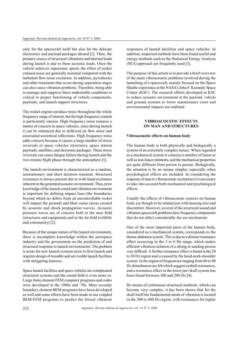
intensity at angles of between 30o and 45o. Figure 2 shows
the noise sources of a supersonic jet. During the Space
Shuttle lift-off turbulent eddies created due to mixing
of hot gases with ambient air lead to shock, which is the
strongest source of noise.
Figure 2. Supersonic jet exhausts noise sources.
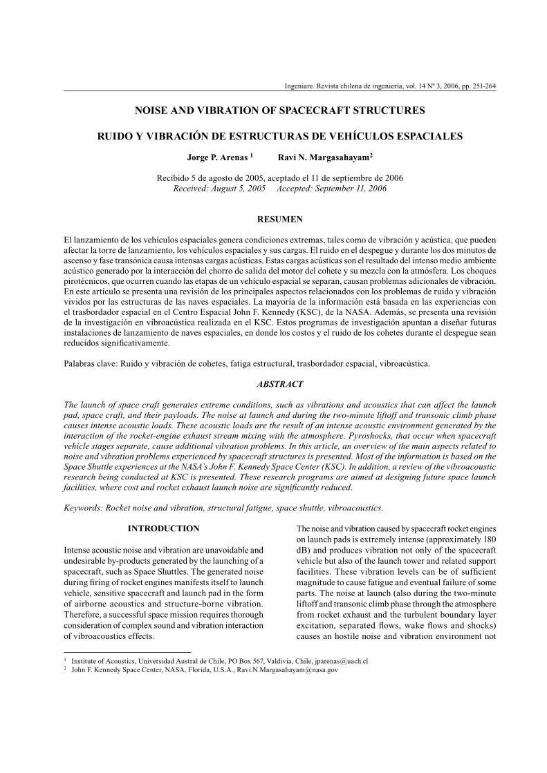
In addition to the case of engine exhaust and nacelle
components, trailing edge wing panels and rear fuselage
panels are often seriously affected. As the total acoustic
power radiated by a jet exhaust is proportional to the eight
power of the jet efflux velocity (between the cube and the
fifth power of the jet efflux velocity for rockets, see figure
3), and the square of the jet diameter, the magnitude of
the acoustic fatigue problem during the launching of a
spacecraft can be readily appreciated.
Figure 3. Acoustic radiation efficiency of noise sources
in the jet exhaust.
The incident acoustic wave generates various modes of
vibration in a structure, causing the stress concentrations
which lead to eventual failure. This consideration
is particularly important to avoid damage to the
payload.
Shock and Transients: a shock is characterized by a sudden
occurrence and a short duration in relation to the natural
frequency of the structure on which the shock is acting. A
transient, however, may last for a time which corresponds
to several cycles at the natural frequency of the structure.
Both phenomena produce a rapid transfer of energy, which
is characterized by the length, rise time, and specific form
of the shock pulse [4]. In general, the shock response
spectrum is used to compare shock motions, to formulate
laboratory tests, and to design structures to withstand
shock inputs. Permanent damage need not necessarily
take place for a structural system to fail a shock test, so
a simple test of destruction may not always be sufficient
to assure survivability. In addition, the characteristics of
the shock environment must be known with reasonable
accuracy in order to ensure that environmental tests are
valid. For this reason, measured time histories are often
used as laboratory tests excitations in order to reproduce
the actual conditions experienced in use.
Pyrotechnic shock, or pyroshock, is the transient response
of a structure to loading induced by the ignition of
pyrotechnic (explosive or propellant activated) devices
[10]. These devices are typically used to separate
structural systems (e.g., separate a spacecraft from a
launch vehicle) and deploy appendages (e.g., solar panels).
Pyroshock is characterized by high peak acceleration,
high-frequency content, and short duration. Because of
their high acceleration and high frequency, pyroshock
can cause spaceflight hardware to fail. Verifying by tests
that spaceflight hardware can withstand the anticipated
shock environment is considered essential to mission
success.

Arenas et al.: Noise and vibration of spacecraft structures
Ingeniare. Revista chilena de ingeniería, vol. 14 Nº 3, 2006 255
In practical cases, the actual mode of failure and time
to failure are dominated by the local physical features
of the structure as well as external factors such as
corrosion, temperature, pre-treatment, etc. The failure
of a structure is therefore dominated by the weakest
link in the failure chain and much effort is required to
identify and eliminate them. Fatigue cracks may begin
form stress concentrations at sharp corners, surface
irregularities or damage, or welds. Large welded
structures in a corrosive environment under the action
of continuous random vibroacoustic excitation, such
as in the case of spacecraft structures, are particularly
susceptible to failures emanating from discontinuities
in welds.
On the other hand, acoustic blankets have been used in the
payload fairing of expendable launch vehicles to reduce
the fairing’s interior acoustics and subsequent vibration
response of a spacecraft [10]. For example, the Cassini
spacecraft (see figure 4), launched on a Titan IV/Centaur
in October 1997, required lower acoustic levels in order
to avoid an extremely costly vibration requalification of
the Cassini’s spacecraft on-board electric power source
known as the Radioisotope Thermoelectric Generator
(RTG). Thus, new acoustic blankets were developed and
tested to reach NASA’s goal of reducing the Titan IV
acoustic environment to allowable levels for the Cassini
spacecraft and RTGs [11].
Figure 4. Cassini spacecraft.
LAUNCH PAD VIBROACOUSTICS
As discussed above, spacecrafts are subjected to a variety
of dynamic environments, which may include: quasi-static
vibration and acoustic loads at launch, pyrotechnic shocks
generated by separation mechanisms, on-orbit jitter,
and sometimes, planetary landing loads [12]. Figure 5
shows the launch of a Space Shuttle from NASA’s KSC.
Given the extend of the jet plume, one can only imagine
the severe noise and vibration environment which a
spacecraft, launched by the shuttle or by an Expendable
Launch Vehicle (ELV), must survive. In particular, the
launch pad and ground support equipment and structures
in the proximity of the launch pad are subjected to
intense acoustic pressures generated by rocket exhausts.
Vibroacoustic coupling is a measure of a structure’s
tendency to vibrate when subjected to acoustic loads.
This vibration can lead to degradation of a structure,
resulting in increased maintenance costs.
Figure 5. Launch of a space shuttle.
The design of launch pad structures, particularly those
having a large area-to-mass ratio, is governed by launch-
induced acoustic pressures, which are relatively short
transient (less than 20 seconds) with random amplitudes
and exhibiting a non-Gaussian distribution. The factors
influencing acoustic excitation or forcing on any pad
structure are numerous (acoustic efficiency, clustered
and homogeneity of rocket engines, varying diameters,
launch trajectory, pad placement of structure, atmospheric
conditions, shielding, etc.).
The launch pads, second only to the massive Vehicle
Assembly Building, are signature features of the NASA’s
John F. Kennedy Space Center (KSC) landscape. The
pads were originally built for the huge Apollo/Saturn V
rockets that launched astronauts on their historic journeys
to the moon and back (see figure 6).
Ingeniare. Revista chilena de ingeniería, vol. 14 Nº 3, 2006
Ingeniare. Revista chilena de ingeniería, vol. 14 Nº 3, 2006
256
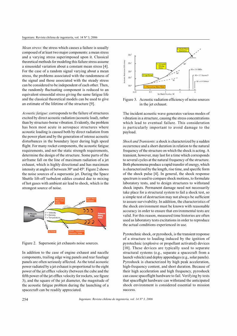
Figure 6. Saturn V on launch pad 39A.
Following the joint U.S.-Soviet Apollo-Soyuz Test Project
mission of July 1975, the pads were modified to support
Space Shuttle operations (see figure 7). Most significant
manned space flight and related endeavors, such as Apollo,
Skylab, Apollo-Soyuz, Hubble Space Telescope and the
International Space Station, originated there.
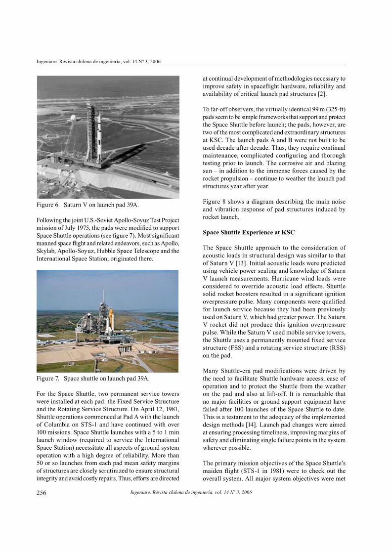
Figure 7. Space shuttle on launch pad 39A.
For the Space Shuttle, two permanent service towers
were installed at each pad: the Fixed Service Structure
and the Rotating Service Structure. On April 12, 1981,
Shuttle operations commenced at Pad A with the launch
of Columbia on STS-1 and have continued with over
100 missions. Space Shuttle launches with a 5 to 1 min
launch window (required to service the International
Space Station) necessitate all aspects of ground system
operation with a high degree of reliability. More than
50 or so launches from each pad mean safety margins
of structures are closely scrutinized to ensure structural
integrity and avoid costly repairs. Thus, efforts are directed
at continual development of methodologies necessary to
improve safety in spaceflight hardware, reliability and
availability of critical launch pad structures [2].
To far-off observers, the virtually identical 99 m (325-ft)
pads seem to be simple frameworks that support and protect
the Space Shuttle before launch; the pads, however, are
two of the most complicated and extraordinary structures
at KSC. The launch pads A and B were not built to be
used decade after decade. Thus, they require continual
maintenance, complicated configuring and thorough
testing prior to launch. The corrosive air and blazing
sun – in addition to the immense forces caused by the
rocket propulsion – continue to weather the launch pad
structures year after year.
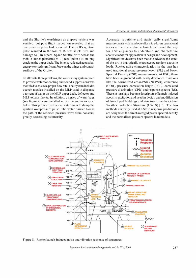
Figure 8 shows a diagram describing the main noise
and vibration response of pad structures induced by
rocket launch.
Space Shuttle Experience at KSC
The Space Shuttle approach to the consideration of
acoustic loads in structural design was similar to that
of Saturn V [13]. Initial acoustic loads were predicted
using vehicle power scaling and knowledge of Saturn
V launch measurements. Hurricane wind loads were
considered to override acoustic load effects. Shuttle
solid rocket boosters resulted in a significant ignition
overpressure pulse. Many components were qualified
for launch service because they had been previously
used on Saturn V, which had greater power. The Saturn
V rocket did not produce this ignition overpressure
pulse. While the Saturn V used mobile service towers,
the Shuttle uses a permanently mounted fixed service
structure (FSS) and a rotating service structure (RSS)
on the pad.
Many Shuttle-era pad modifications were driven by
the need to facilitate Shuttle hardware access, ease of
operation and to protect the Shuttle from the weather
on the pad and also at lift-off. It is remarkable that
no major facilities or ground support equipment have
failed after 100 launches of the Space Shuttle to date.
This is a testament to the adequacy of the implemented
design methods [14]. Launch pad changes were aimed
at ensuring processing timeliness, improving margins of
safety and eliminating single failure points in the system
wherever possible.
The primary mission objectives of the Space Shuttle’s
maiden flight (STS-1 in 1981) were to check out the
overall system. All major system objectives were met
Arenas et al.: Noise and vibration of spacecraft structures
Ingeniare. Revista chilena de ingeniería, vol. 14 Nº 3, 2006 257
and the Shuttle’s worthiness as a space vehicle was
verified, but post flight inspection revealed that an
overpressure pulse had occurred. The SRB’s ignition
pulse resulted in the loss of 16 heat shield tiles and
damage to 148 others. Space Shuttle drift across the
mobile launch platform (MLP) resulted in a 9.1 m long
crack on the upper deck. The intense reflected acoustical
energy exerted significant force on the wings and control
surfaces of the Orbiter.
To alleviate these problems, the water spray system (used
to provide water for cooling and sound suppression) was
modified to ensure a proper flow rate. That system includes
quench nozzles installed on the MLP used to dispense
a torrent of water on the MLP upper deck, deflector and
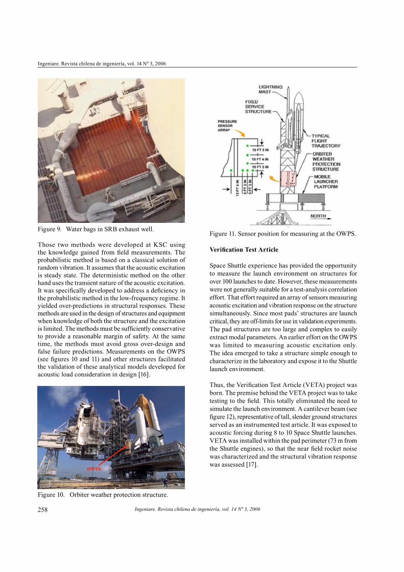
MLP exhaust holes. In addition, a series of water bags
(see figure 9) were installed across the engine exhaust
holes. This provided sufficient water mass to damp the
ignition overpressure pulse. The water barrier blocks
the path of the reflected pressure wave from boosters,
greatly decreasing its intensity.
Accurate, repetitive and statistically significant
measurements with hands-on efforts to address operational
issues at the Space Shuttle launch pad paved the way
for KSC engineers to understand and characterize
acoustic loads for application in design and development.
Significant strides have been made to advance the state-
of-the-art to analytically characterize random acoustic
loads. Rocket noise characterization in the past has
used traditional sound pressure level (SPL) and Power
Spectral Density (PSD) measurements. At KSC, these
have been augmented with newly developed functions
like the normalized cross-PSD (NCPSD), coherence
(COH), pressure correlation length (PCL), correlated
pressure distribution (CPD) and response spectra (RS).
These in turn have become descriptors of launch-induced
acoustic excitation and used in design and modification
of launch pad buildings and structures like the Orbiter
Weather Protection Structure (OWPS) [15]. The two
methods currently used at KSC in response predictions
are designated the direct averaged power spectral density
and the normalized pressure spectra load models.
Figure 8. Rocket launch-induced noise and vibration response of structures.
Ingeniare. Revista chilena de ingeniería, vol. 14 Nº 3, 2006
Ingeniare. Revista chilena de ingeniería, vol. 14 Nº 3, 2006
258
Figure 9. Water bags in SRB exhaust well.
Those two methods were developed at KSC using
the knowledge gained from field measurements. The
probabilistic method is based on a classical solution of
random vibration. It assumes that the acoustic excitation
is steady state. The deterministic method on the other
hand uses the transient nature of the acoustic excitation.
It was specifically developed to address a deficiency in
the probabilistic method in the low-frequency regime. It
yielded over-predictions in structural responses. These
methods are used in the design of structures and equipment
when knowledge of both the structure and the excitation
is limited. The methods must be sufficiently conservative
to provide a reasonable margin of safety. At the same
time, the methods must avoid gross over-design and
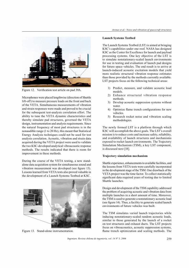
false failure predictions. Measurements on the OWPS
(see figures 10 and 11) and other structures facilitated
the validation of these analytical models developed for
acoustic load consideration in design [16].
Figure 10. Orbiter weather protection structure.
Figure 11. Sensor position for measuring at the OWPS.
Verification Test Article
Space Shuttle experience has provided the opportunity
to measure the launch environment on structures for
over 100 launches to date. However, these measurements
were not generally suitable for a test-analysis correlation
effort. That effort required an array of sensors measuring
acoustic excitation and vibration response on the structure
simultaneously. Since most pads’ structures are launch
critical, they are off-limits for use in validation experiments.
The pad structures are too large and complex to easily
extract modal parameters. An earlier effort on the OWPS
was limited to measuring acoustic excitation only.
The idea emerged to take a structure simple enough to
characterize in the laboratory and expose it to the Shuttle
launch environment.
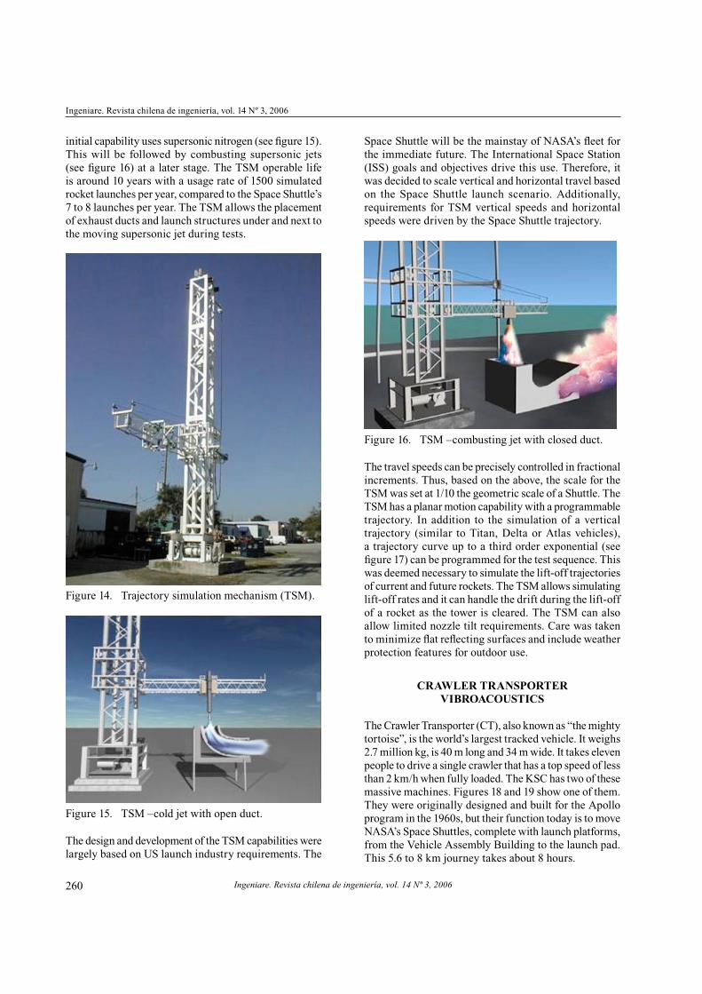
Thus, the Verification Test Article (VETA) project was
born. The premise behind the VETA project was to take
testing to the field. This totally eliminated the need to
simulate the launch environment. A cantilever beam (see
figure 12), representative of tall, slender ground structures
served as an instrumented test article. It was exposed to
acoustic forcing during 8 to 10 Space Shuttle launches.
VETA was installed within the pad perimeter (73 m from
the Shuttle engines), so that the near field rocket noise
was characterized and the structural vibration response
was assessed [17].
Arenas et al.: Noise and vibration of spacecraft structures
Ingeniare. Revista chilena de ingeniería, vol. 14 Nº 3, 2006 259
Figure 12. Verification test article on pad 39A.
Microphones were placed lengthwise (direction of Shuttle
lift-off) to measure pressure loads on the front and back
of the VETA. Simultaneous measurements of vibration
and strain responses were made and proved to be crucial
for the subsequent test-analysis correlation effort. The
ability to tune the VETA dynamic characteristics and
thereby simulate pad structures, governed the VETA
design, instrumentation and analysis requirements. Since
the natural frequency of most pad structures is in the
nonaudible range (1 to 20 Hz), this meant that Statistical
Energy Analysis techniques could not be used for test
analysis correlation. Acoustic, vibration and strain data
acquired during the VETA project were used to validate
the two KSC-developed analytical vibroacoustic response
methods. The results indicated that there is room for
improvement in these methods.
During the course of the VETA testing, a new stand-
alone data acquisition system for simultaneous sound and
vibration measurement was developed (see figure 13).
Lessons learned from VETA tests also proved valuable in
the development of a Launch Systems Testbed at KSC.
Figure 13. Stand-alone instrumentation.
Launch Systems Testbed
The Launch Systems Testbed (LST) is aimed at bringing
KSC’s capabilities under one roof. NASA has designed
KSC as the Center for Excellence for launch and payload
processing systems. One key objective of the LST is
to simulate nonstationary-scaled launch environments
for use in testing and evaluation of launch pad designs
for future space vehicles. The end result is to arrive at
launch-induced acoustic excitation models that yield
more realistic structural vibration response estimates
than those provided by the methods currently available.
LST projects focus on the following technical areas:
1) Predict, measure, and validate acoustic load
models.
2) Enhance st ructural vibration response
methods.
3) Develop acoustic suppression systems without
water.
4) Optimize flame trench configurations for new
vehicles.
5) Research rocket noise and vibration scaling
methodologies.
The newly formed LST is a platform through which
KSC will accomplish the above goals. The LST’s overall
mission is to reduce costs and increase safety, reliability,
and availability of launch structures and mechanisms
exposed to rocket launch environments. The Trajectory
Simulation Mechanism (TSM), a key LST component,
is discussed next [18].
Trajectory simulation mechanism
Shuttle experience, enhancements to available facilities, and
the lessons from VETA tests were carefully incorporated
in the development stage of the TSM. One drawback of the
VETA project was the time factor. To collect statistically
significant data required years of testing due to limited
Shuttle launches.
Design and development of the TSM capability addressed
the problem of acquiring acoustic and vibration data from
multiple launches in a short amount of time. Moreover,
the TSM is used to generate a nonstationary acoustic load
(see figure 14). Thus, a facility to generate scaled launch
environments of future vehicles was built.
The TSM simulates varied launch trajectories while
inducing nonstationary-scaled random acoustic loads,
similar to those generated by the launch of a rocket
on test structures and exhaust ducts. The LST projects
focus on vibroacoustics, acoustic suppression systems,
flame trench optimization and scaling methods. The
Ingeniare. Revista chilena de ingeniería, vol. 14 Nº 3, 2006
Ingeniare. Revista chilena de ingeniería, vol. 14 Nº 3, 2006
260
initial capability uses supersonic nitrogen (see figure 15).
This will be followed by combusting supersonic jets
(see figure 16) at a later stage. The TSM operable life
is around 10 years with a usage rate of 1500 simulated
rocket launches per year, compared to the Space Shuttle’s
7 to 8 launches per year. The TSM allows the placement
of exhaust ducts and launch structures under and next to
the moving supersonic jet during tests.
Figure 14. Trajectory simulation mechanism (TSM).
Figure 15. TSM –cold jet with open duct.
The design and development of the TSM capabilities were
largely based on US launch industry requirements. The
Space Shuttle will be the mainstay of NASA’s fleet for
the immediate future. The International Space Station
(ISS) goals and objectives drive this use. Therefore, it
was decided to scale vertical and horizontal travel based
on the Space Shuttle launch scenario. Additionally,
requirements for TSM vertical speeds and horizontal
speeds were driven by the Space Shuttle trajectory.
Figure 16. TSM –combusting jet with closed duct.
The travel speeds can be precisely controlled in fractional
increments. Thus, based on the above, the scale for the
TSM was set at 1/10 the geometric scale of a Shuttle. The
TSM has a planar motion capability with a programmable
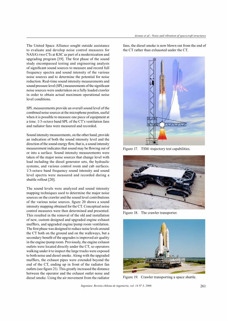
trajectory. In addition to the simulation of a vertical
trajectory (similar to Titan, Delta or Atlas vehicles),
a trajectory curve up to a third order exponential (see
figure 17) can be programmed for the test sequence. This
was deemed necessary to simulate the lift-off trajectories
of current and future rockets. The TSM allows simulating
lift-off rates and it can handle the drift during the lift-off
of a rocket as the tower is cleared. The TSM can also
allow limited nozzle tilt requirements. Care was taken
to minimize flat reflecting surfaces and include weather
protection features for outdoor use.
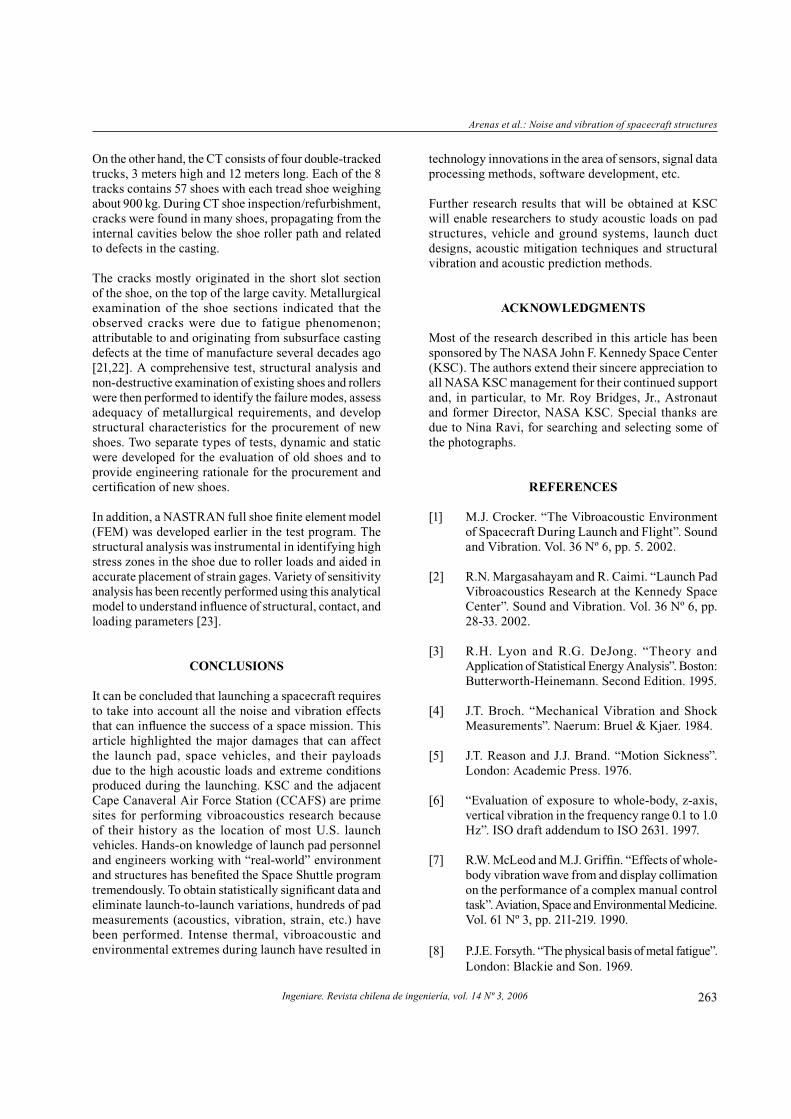
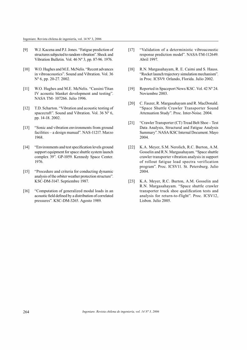
CRAWLER TRANSPORTER VIBROACOUSTICS
The Crawler Transporter (CT), also known as “the mighty
tortoise”, is the world’s largest tracked vehicle. It weighs
2.7 million kg, is 40 m long and 34 m wide. It takes eleven
people to drive a single crawler that has a top speed of less
than 2 km/h when fully loaded. The KSC has two of these
massive machines. Figures 18 and 19 show one of them.
They were originally designed and built for the Apollo
program in the 1960s, but their function today is to move
NASA’s Space Shuttles, complete with launch platforms,
from the Vehicle Assembly Building to the launch pad.
This 5.6 to 8 km journey takes about 8 hours.
Arenas et al.: Noise and vibration of spacecraft structures
Ingeniare. Revista chilena de ingeniería, vol. 14 Nº 3, 2006 261
The United Space Alliance sought outside assistance
to evaluate and develop noise control measures for
NASA’s two CTs at KSC as part of a modernization and
upgrading program [19]. The first phase of the sound
study encompassed testing and engineering analysis
of significant sound sources to measure and record full
frequency spectra and sound intensity of the various
noise sources and to determine the potential for noise
reduction. Real-time sound intensity measurements and
sound pressure level (SPL) measurements of the significant
noise sources were undertaken on a fully loaded crawler
in order to obtain actual maximum operational noise
level conditions.
SPL measurements provide an overall sound level of the
combined noise sources at the microphone position, useful
when it is possible to measure one piece of equipment at
a time. 1/3-octave band SPL of the CT’s ventilation fans
and radiator fans were measured and recorded.
Sound intensity measurements, on the other hand, provide
an indication of both the sound intensity level and the
direction of the sound energy flow, that is, a sound intensity
measurement indicates that sound may be flowing out of
or into a surface. Sound intensity measurements were
taken of the major noise sources that change level with
load including the diesel generator sets, the hydraulic
systems, and various control room and cab surfaces.
1/3-octave band frequency sound intensity and sound
level spectra were measured and recorded during a
shuttle rollout [20].
The sound levels were analyzed and sound intensity
mapping techniques used to determine the major noise
sources on the crawler and the sound level contributions
of the various noise sources. figure 20 shows a sound
intensity mapping obtained for the CT. Conceptual noise
control measures were then determined and presented.
This resulted in the removal of the old and installation
of new, custom designed and upgraded engine exhaust
mufflers, and upgraded engine/pump room ventilation.
The first phase was designed to reduce noise levels around
the CT both on the ground and on the walkways, but a
secondary benefit of the upgrades is improved air quality
in the engine/pump room. Previously, the engine exhaust
outlets were located directly under the CT, so operators
walking under it to inspect the large trucks were exposed
to both noise and diesel smoke. Along with the upgraded
mufflers, the exhaust pipes were extended beyond the
end of the CT, ending up in front of the radiator fan
outlets (see figure 21). This greatly increased the distance
between the operator and the exhaust outlet noise and
diesel smoke. Using the air movement from the radiator
fans, the diesel smoke is now blown out from the end of
the CT rather than exhausted under the CT.
Figure 17. TSM–trajectory test capabilities.
Figure 18. The crawler transporter.
Figure 19. Crawler transporting a space shuttle.

Ingeniare. Revista chilena de ingeniería, vol. 14 Nº 3, 2006
Ingeniare. Revista chilena de ingeniería, vol. 14 Nº 3, 2006
262
Figure 20. 400 Hz sound intensity contours for the CT
when traveling to the pad ramp.
In the past, the ventilation air was drawn in from the
sidewalls of the engine/pump room where it would first
sweep across the engines before being driven down over
the workers and exhausted out through twelve louvered
outlets in the floor. The ventilation air is now drawn in
from under the CT through twelve filtered and acoustically
treated inlet hoods, thus using the coolest air available.
The cool air is forced up through the floor grates, and
first sweeps across the workers. It then flows across the
engines to the ceiling where it is exhausted via fourteen
silenced outlets.
This change in airflow direction as well as the increased
volume of ventilation air allows the engine/pump room
to operate with a greatly reduced temperature increase,
and allows the doors to remain closed during operation.
The closed doors in conjunction with the silenced floor
and wall ventilation openings have significantly reduced
noise levels around the CT, both on the catwalks and on
the ground, enhancing operational conditions for the CT
crew. Table 1 shows a summary of the noise reductions
achieved after phase 1.
Figure 21. Exhaust pipes and upgraded mufflers.
Table 1. Noise reductions at the CT after phase 1.
Description
Measured sound levels
(dBA)Reduction
noise (dBA)
Before After
CT side ventilation air exhaust
openings101 77 24
CT end ventilation air exhaust
openings101 85 16
Existing 6 blade ventilation air
intake openings88 72 16
Existing 2 blade ventilation air
intake openings91 72 19
On catwalk, engine room door
open and closed97 86 11
White engines 600 rpm exhaust
outlet85 75 10
White engines 900 rpm exhaust
outlet91 86 5
Alco engines 900 rpm exhaust
outlet80 67 13
Alco engines 1000 rpm exhaust
outlet93 84 9
The second phase of the noise-control plan is to suppress
the JEL (jacking, equalization, leveling) hydraulic systems
noise. The hydraulic systems are all rigidly mounted on
the CT’s superstructure and use rigid piping except for the
final connections to the hydraulic cylinders. The pump
tone generated by the systems was identified as one of
the major noise sources in both the control room and the
driver cabs, even though the hydraulic lines do not run
directly under these areas. The JEL system noise-control
measures include mounting the JEL motors and pump
skids on rubber isolators, the use of elastomeric pipe-
mounting clamps to isolate the hydraulic lines from the
CT’s superstructure, installation of flexible hose between
the pumps and the rigid hydraulic lines, and installation
of in-line hydraulic silencers to reduce the pump tone.
The third phase will encompass the installation of acoustical
absorption on the walls and ceilings of the engine/pump
room, use of sound lock vestibules at the engine/pump
room’s doors, and application of an upgraded sound
reduction wall between the engine/pump room and the
control room. This will reduce the noise levels in the
control room, and lower noise levels outside the CT due
to a decrease in the reverberant sound level inside the
engine/pump room.
Arenas et al.: Noise and vibration of spacecraft structures
Ingeniare. Revista chilena de ingeniería, vol. 14 Nº 3, 2006 263
On the other hand, the CT consists of four double-tracked
trucks, 3 meters high and 12 meters long. Each of the 8
tracks contains 57 shoes with each tread shoe weighing
about 900 kg. During CT shoe inspection/refurbishment,
cracks were found in many shoes, propagating from the
internal cavities below the shoe roller path and related
to defects in the casting.
The cracks mostly originated in the short slot section
of the shoe, on the top of the large cavity. Metallurgical
examination of the shoe sections indicated that the
observed cracks were due to fatigue phenomenon;
attributable to and originating from subsurface casting
defects at the time of manufacture several decades ago
[21,22]. A comprehensive test, structural analysis and
non-destructive examination of existing shoes and rollers
were then performed to identify the failure modes, assess
adequacy of metallurgical requirements, and develop
structural characteristics for the procurement of new
shoes. Two separate types of tests, dynamic and static
were developed for the evaluation of old shoes and to
provide engineering rationale for the procurement and
certification of new shoes.
In addition, a NASTRAN full shoe finite element model
(FEM) was developed earlier in the test program. The
structural analysis was instrumental in identifying high
stress zones in the shoe due to roller loads and aided in
accurate placement of strain gages. Variety of sensitivity
analysis has been recently performed using this analytical
model to understand influence of structural, contact, and
loading parameters [23].
CONCLUSIONS
It can be concluded that launching a spacecraft requires
to take into account all the noise and vibration effects
that can influence the success of a space mission. This
article highlighted the major damages that can affect
the launch pad, space vehicles, and their payloads
due to the high acoustic loads and extreme conditions
produced during the launching. KSC and the adjacent
Cape Canaveral Air Force Station (CCAFS) are prime
sites for performing vibroacoustics research because
of their history as the location of most U.S. launch
vehicles. Hands-on knowledge of launch pad personnel
and engineers working with “real-world” environment
and structures has benefited the Space Shuttle program
tremendously. To obtain statistically significant data and
eliminate launch-to-launch variations, hundreds of pad
measurements (acoustics, vibration, strain, etc.) have
been performed. Intense thermal, vibroacoustic and
environmental extremes during launch have resulted in
technology innovations in the area of sensors, signal data
processing methods, software development, etc.
Further research results that will be obtained at KSC
will enable researchers to study acoustic loads on pad
structures, vehicle and ground systems, launch duct
designs, acoustic mitigation techniques and structural
vibration and acoustic prediction methods.
ACKNOWLEDGMENTS
Most of the research described in this article has been
sponsored by The NASA John F. Kennedy Space Center
(KSC). The authors extend their sincere appreciation to
all NASA KSC management for their continued support
and, in particular, to Mr. Roy Bridges, Jr., Astronaut
and former Director, NASA KSC. Special thanks are
due to Nina Ravi, for searching and selecting some of
the photographs.
REFERENCES
[1] M.J. Crocker. “The Vibroacoustic Environment
of Spacecraft During Launch and Flight”. Sound
and Vibration. Vol. 36 Nº 6, pp. 5. 2002.
[2] R.N. Margasahayam and R. Caimi. “Launch Pad
Vibroacoustics Research at the Kennedy Space
Center”. Sound and Vibration. Vol. 36 Nº 6, pp.
28-33. 2002.
[3] R.H. Lyon and R.G. DeJong. “Theory and
Application of Statistical Energy Analysis”. Boston:
Butterworth-Heinemann. Second Edition. 1995.
[4] J.T. Broch. “Mechanical Vibration and Shock
Measurements”. Naerum: Bruel & Kjaer. 1984.
[5] J.T. Reason and J.J. Brand. “Motion Sickness”.
London: Academic Press. 1976.
[6] “Evaluation of exposure to whole-body, z-axis,
vertical vibration in the frequency range 0.1 to 1.0
Hz”. ISO draft addendum to ISO 2631. 1997.
[7] R.W. McLeod and M.J. Griffin. “Effects of whole-
body vibration wave from and display collimation
on the performance of a complex manual control
task”. Aviation, Space and Environmental Medicine.
Vol. 61 Nº 3, pp. 211-219. 1990.
[8] P.J.E. Forsyth. “The physical basis of metal fatigue”.
London: Blackie and Son. 1969.
Ingeniare. Revista chilena de ingeniería, vol. 14 Nº 3, 2006
Ingeniare. Revista chilena de ingeniería, vol. 14 Nº 3, 2006
264
[9] W.J. Kacena and P.J. Jones. “Fatigue prediction of
structures subjected to random vibration”. Shock and
Vibration Bulletin. Vol. 46 Nº 3, pp. 87-96. 1976.
[10] W.O. Hughes and M.E. McNelis. “Recent advances
in vibroacoustics”. Sound and Vibration. Vol. 36
Nº 6, pp. 20-27. 2002.
[11] W.O. Hughes and M.E. McNelis. “Cassini/Titan
IV acoustic blanket development and testing”.
NASA TM- 107266. Julio 1996.
[12] T.D. Scharton. “Vibration and acoustic testing of
spacecraft”. Sound and Vibration. Vol. 36 Nº 6,
pp. 14-18. 2002.
[13] “Sonic and vibration environments from ground
facilities – a design manual”. NAS-11217. Marzo
1968.
[14] “Environments and test specification levels ground
support equipment for space shuttle system launch
complex 39”. GP-1059. Kennedy Space Center.
1976.
[15] “Procedure and criteria for conducting dynamic
analysis of the orbiter weather protection structure”.
KSC-DM-3147. Septiembre 1987.
[16] “Computation of generalized modal loads in an
acoustic field defined by a distribution of correlated
pressures”. KSC-DM-3265. Agosto 1989.
[17] “Validation of a deterministic vibroacoustic
response prediction model”. NASA-TM-112649.
Abril 1997.
[18] R.N. Margasahayam, R. E. Caimi and S. Hauss.
“Rocket launch trajectory simulation mechanism”.
in Proc. ICSV9. Orlando, Florida. Julio 2002.
[19] Reported in Spaceport News/KSC. Vol. 42 Nº 24.
Noviembre 2003.
[20] C. Faszer, R. Margasahayam and R. MacDonald.
“Space Shuttle Crawler Transporter Sound
Attenuation Study”. Proc. Inter-Noise. 2004.
[21] “Crawler Transporter (CT) Tread Belt Shoe – Test
Data Analysis, Structural and Fatigue Analysis
Summary”. NASA/KSC Internal Document. Mayo
2004.
[22] K.A. Meyer, S.M. Nerolich, R.C. Burton, A.M.
Gosselin and R.N. Margasahayam. “Space shuttle
crawler transporter vibration analysis in support
of rollout fatigue load spectra verification
program”. Proc. ICSV11. St. Petersburg. Julio
2004.
[23] K.A. Meyer, R.C. Burton, A.M. Gosselin and
R.N. Margasahayam. “Space shuttle crawler
transporter truck shoe qualification tests and
analysis for return-to-f light”. Proc. ICSV12,
Lisbon. Julio 2005.