atm defined asynchronous transfer mode (atm) is a cell-based switching and multiplexing technology...
TRANSCRIPT

ATM Defined Asynchronous Transfer Mode (ATM) is a cell-based
switching and multiplexing technology designed to be a general-purpose, connection-oriented transfer mode for a wide range of services
ATM has been applied to LAN and private network technologies as specified by the ATM Forum for Token Ring, Ethernet, and FDDI LAN Emulation (LANE)
ATM handles both connection-oriented traffic directly (cell-based) or through adaptation layers, or connectionless traffic through the use of adaptation layers
ATM Defined (Continue…) ATM virtual connections may operate at either a
Constant Bit Rate (CBR) or a Variable Bit Rate (VBR) Each ATM cell sent into the network contains addressing
information that achieves a virtual connection from origination to destination. All cells are transferred in sequence
ATM provides two modes for the establishment of virtual connections: Permanent or Switched Virtual Connections (PVC or SVC)
ATM Defined (Continue…) ATM is asynchronous because the transmitted cells
need not be periodic as time slots for data are required to be in Synchronous Transfer Mode (STM)
ATM offers the potential to standardize on one network architecture defining the multiplexing and switching method, with SONET.STM providing the basis for the physical transmission standard as very high speeds
ATM supports multiple Quality of Service (QoS) classes for differing application requirements on delay and loss performance
ATM as an Interface and Protocol ATM is defined as an interface and protocol designed to
switch variable bit-rate and constant bit-rate traffic over a common transmission medium
The entire B-ISDN protocol stack is often referred to as ATM
ATM offers technology and protocol structure to enable you to utilize existing and extended capabilities such as LAN, FTP, etc…
ATM as Technology ATM technology takes the form of a network interface
card, multiplexer, cross-connect, or even a full switch. Today, ATM is most prevalent in the switch market and
as a WAN interface on traditional data communications products like routers and hubs
ATM as Economical, Integrated Access ATM offers service in reduced cost The TDM access lines can be multiplexed onto an E3,
DS3, or even SONET access line, leaving large amounts of bandwidth available for ATM applications at small incremental cost
ATM as Infrastructure ATM hardware and associated software together can
provide the backbone technology for an advanced communications network

ATM as a Service ATM is not a service, but services can be offered over an
ATM architecture (ex. Cell Relay Service, Switched Multimegabit Data Service, etc.,)

ATM Cell ATM standards define a fixed-size cell with a length of
53 octets (or bytes) comprising a 5-octet header and a 48-octet payload
Refer to Figure 13.1 (p. 515) The bits in the cells are transmitted over the
transmission path from left to right in a continuous stream.
Cells are mapped into a physical transmission path, such as the North American DS1, DS3, or SONET

ATM Cell (Continue…) All information is switched and multiplexed in an ATM
network in these fixed-length cells When using ATM, longer packets cannot delay shorter
packets as in other packet-switched implementations because long packets are chopped up into many cells.
This enables ATM to carry Constant Bit Rate (CBR) traffic such as voice and video in conjunction with Variable Bit Rate (VBR) data traffic, potentially having very long packets within the same network
Refer to Figure 13.3 (p. 517)
Why 53 Bytes? Choice of Payload Size There is a basic tradeoff between efficiency and
packetization delay versus cell size Refer to Figure 13.4 (p. 518) The ITU-T adopted the fixed-length 48-octet (plus 5-octet
header) cell payload as a compromise between a long cell sizes for time-insensitive traffic (64-octets) and small cell sizes for time-sensitive traffic (32 octets)

Transmission Path, Virtual Path, and Virtual Channels
A transmission path contains one or more virtual paths, while each virtual path contains one or more virtual channels
Multiple virtual channels can be trunked within a single virtual path
Switching can be performed on either a transmission-path, virtual-path, or virtual-circuit level
Refer to Figure 13.7 (p. 522)

Transmission Path, Virtual Path, and Virtual Channels (Continue…)
Devices that perform VC connections are commonly called VC switches
Transmission networks use a cross-connect, which is basically a space-division switch, or effectively an electronic patch panel
ATM devices that connect VPs are commonly often called VP cross-connects
Virtual Path Connections (VPCs) and Virtual Channel Connections (VCCs)
Virtual Path Connections (VPCs): are switched based upon the Virtual Path Identifier (VPI) value only.
The users of the PVC may assign the VCCs within that VPI transparently since they follow the same route
Virtual Channel Connections (VCCs): are switched upon the combined VPI and Virtual Channel Identifier (VCI) value
Both VPIs and VCIs are used to route cells through the network
Virtual Path Connections (VPCs) and Virtual Channel Connections (VCCs) (Continue…)
VPI and VCI values must be unique on a specific Transmission Path (TP)
Each TP between two network devices (such as ATM switches) uses VPIs and VCIs independently
Refer to Figure 13.9
A simple ATM Example Refer to Figure 13.10 (p. 525)
An ATM Switch example Refer to Figure 13.11 (p. 526)

B-ISDN Protocol Reference Model The physical layer, ATM layer, and AALs are the
foundation for B-ISDN The user and control planes may make use of common
ATM and physical layer protocols; however, the end purpose differs in the AALs and higher layers
Refer to Figure 13.12 (p. 527)

The Plane-Layer Truth – An Overview The physical layer has two sublayers
– Transmission Convergence (TC): extracts and inserts ATM cells within Plesiochronous or Synchronous (PHD or SDH) Time Division Multiplexed (TDM) frame and passes these to and from the ATM layer, respectively
– Physical Medium: interfaces with the actual physical medium and passes the recovered bit stream to the TC sublayer
The ATM layer performs multiplexing, switching, and control actions based upon information in the ATM cell header and passes cells to, and accepts cells from, the ATM Adaptation Layer (AAL)
Refer to Figure 13.13 (p. 529)

The Plane-Layer Truth – An Overview (Continue…)
The physical layer corresponds to layer 1 in the OSI model. The ATM layer and AAL correspond to parts of OSI layer 2, but the address field of the ATM cell header has a network-wide connotation that is similar to OSI layer 3
Refer to Figure 13.14 (p. 529)

Physical (PHY) Layer The PHY layer provides for transmission of ATM cells
over a physical medium that connects two ATM devices The PHY layer is divided into two sublayers:
– Physical Medium Dependent (PMD) provides for the actual transmission of the bits in the ATM
– Transmission Convergence transforms the flow of cells into a steady flow of bits and bytes for transmission over the physical medium
Physical Links and ATM Virtual Paths and Channels
An ATM device may be either an endpoint or a connecting point for a VP or VC
A Virtual Path Connection (VPC) or a Virtual Channel Connection (VCC) exists only between endpoints
A VP link or a VC link can exist between an endpoint and a connecting point or between connecting points
Refer to Figure 13.19 (p. 537)
VC Level The Virtual Channel Identifier (VCI) in the cell header identifies a
single VC on a particular Virtual Path (VP) Switching at a VC connecting point is done based upon the
combination of virtual path and VCI A VC link is defined as a unidirectional flow of ATM cells with the
same VCI between a VC connecting point and either a VC endpoint or another VC connecting point
A Virtual Channel Connection (VCC) is defined as a concatenated list of VC links.
A VCC defines a unidirectional flow of ATM cells from one user to one or more other users
VP Level Virtual Paths (VPs) define an aggregate bundle of VCs between VP
endpoints. A Virtual Path Identifier (VPI) in the cell header identifies a bundle of
one or more VCs. Switching as a VP connecting point is done based upon the VPI –
the VCI is ignored A VP link is defined as a VP between a VP connecting point and
either a VP endpoint or another VP connecting point A Virtual Path Connection (VPC) is defined as a concatenated list of
VP links. A VPC defines a unidirectional flow of ATM cells from one user to
one or more other users

ATM UNI and NNI Defined The UNI is the interface between the user [or customer premises
equipment (CPE)] and the network switch The NNI is the interface between switches or between networks Refer to Figure 13.20 (p. 539) A fundamental concept of ATM is that switching occurs based upon
the VPI/VCI fields of each cell. Switching done on the VPI only is called a Virtual Path Connection
(VPC) while switching done on both the VPI.VCI values is called a Virtual Channel Connection (VCC)
VPCs/VCCs may be either provisioned as Permanent Virtual Circuits (PVCs), or established via signaling protocols as Switched Virtual Circuits (SVCs)

Relaying and Multiplexing Using the VPI/VCI The number of bits allocated in the ATM cell header limit
each physical UNI to support of no more than 28 = 256 virtual paths and each physical NNI to support of no more than 212 = 4096 virtual paths
Each virtual path can support no more than 216 = 65,536 virtual channels on the UNI or the NNI
The number of virtual paths and virtual channels actually supported in a live ATM network may be far less than the maximum numbers defined above

Relaying and Multiplexing Using the VPI/VCI (Continue…)
This has important implications in interoperability if one ATM device expects the next ATM device to operate on VPI/VCI bits, but that device ignores these bits
One way to handle this is to allow each system to query the other about the number of bits that is supported

Cisco
Wide Area Networking Protocols

Objectives
Identify PPP operations to encapsulate WAN data on Cisco routers
Configure authentication with PPP Understand how Frame Relay works on a large WAN network Configure Frame Relay LMIs, maps, and subinterfaces Monitor Frame Relay operation in the router Understand the ISDN protocols, function groups, and reference
points Describe how Cisco implements ISDN BRI
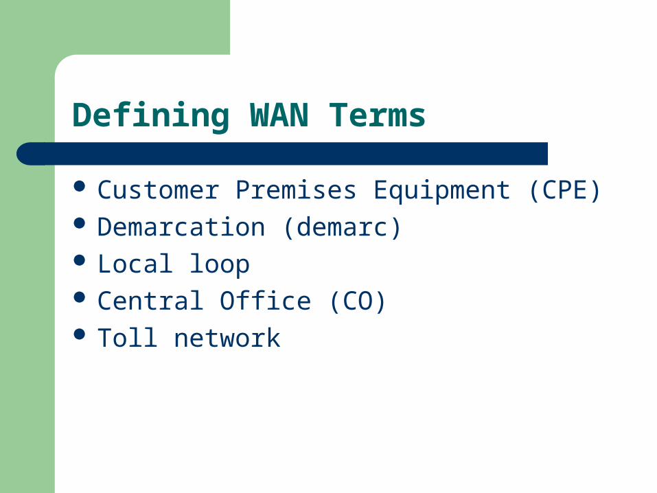
Defining WAN Terms
Customer Premises Equipment (CPE) Demarcation (demarc) Local loop Central Office (CO) Toll network

WAN Connection Types
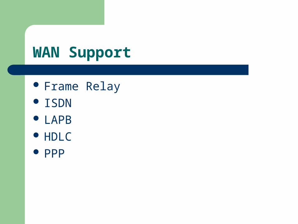
WAN Support
Frame Relay ISDN LAPB HDLC PPP

HDLC Protocol
Bit-oriented Data Link layer ISO standard protocol
Specifies a data encapsulation method PtP protocol used on leased lines No authentication can be used

HDLC Frame Format

Point-to-Point Protocol (PPP)
Purpose:– Transport layer-3 packets across a Data Link layer
point-to-point link
Can be used over asynchronous serial (dial-up) or synchronous serial (ISDN) media– Uses Link Control Protocol (LCP)
Builds & maintains data-link connections

Point-to-Point Protocol Stack

PPP Main Components
EIA/TIA-232-C– Intl. Std. for serial communications
HDLC– Serial link datagram encapsulation method
LCP– Used in P-t-P connections:
Establishing Maintaining Terminating
NCP– Method of establishing & configuring Network Layer
protocols– Allows simultaneous use of multiple Network layer
protocols
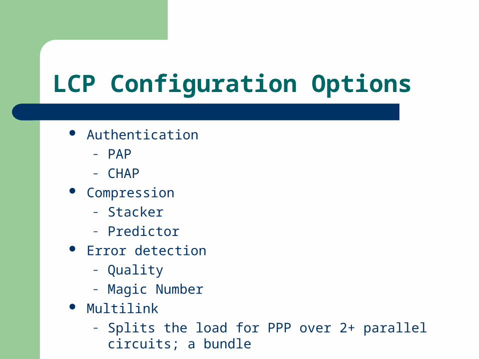
LCP Configuration Options
Authentication– PAP– CHAP
Compression– Stacker– Predictor
Error detection– Quality– Magic Number
Multilink– Splits the load for PPP over 2+ parallel circuits; a
bundle

PPP Session Establishment
Link-establishment phase
Authentication phase
Network-layer protocol phase
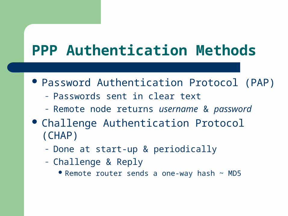
PPP Authentication Methods
Password Authentication Protocol (PAP)– Passwords sent in clear text– Remote node returns username & password
Challenge Authentication Protocol (CHAP)– Done at start-up & periodically– Challenge & Reply
Remote router sends a one-way hash ~ MD5

Configuring PPP
Step #1: Configure PPP on RouterA & RouterB:Router__#config t
Router__(config)#int s0
Router__(config-if)#encapsulation ppp
Router__(config-if)#^Z Step #2: Define the username & password on each router:
– RouterA: RouterA(config)#username RouterB password cisco– RouterB: RouterB(config)#username RouterA password cisco
NOTE: (1) Username maps to the remoteremote router
(2) Passwords must match Step #3: Choose Authentication type for each router; CHAP/PAP
Router__(Config)#int s0
Router__(config-if)#ppp authentication chap
Router__(config-if)#ppp authentication pap
Router__(config-if)#^Z
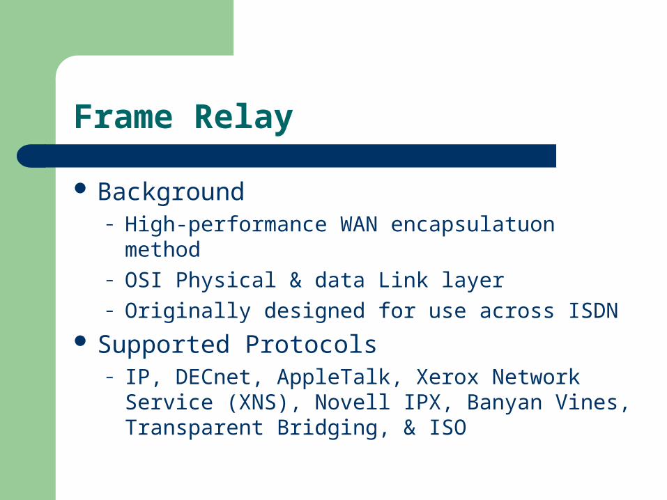
Frame Relay
Background– High-performance WAN encapsulatuon method– OSI Physical & data Link layer– Originally designed for use across ISDN
Supported Protocols– IP, DECnet, AppleTalk, Xerox Network Service
(XNS), Novell IPX, Banyan Vines, Transparent Bridging, & ISO

Frame Relay
Purpose– Provide a communications interface between DTE &
DCE equipment– Connection-oriented Data Link layer communication
Via virtual circuits Provides a complete path from the source to destination
before sending the first frame

Frame Relay Terminology

Frame Relay Encapsulation
Specified on serial interfaces Encapsulation types:
– Cisco (default encapsulation type)– IETF (used between Cisco & non-Cisco devices)
RouterA(config)#int s0
RouterA(config-if)#encapsulation frame-relay ? ietf Use RFC1490 encapsulation <cr>
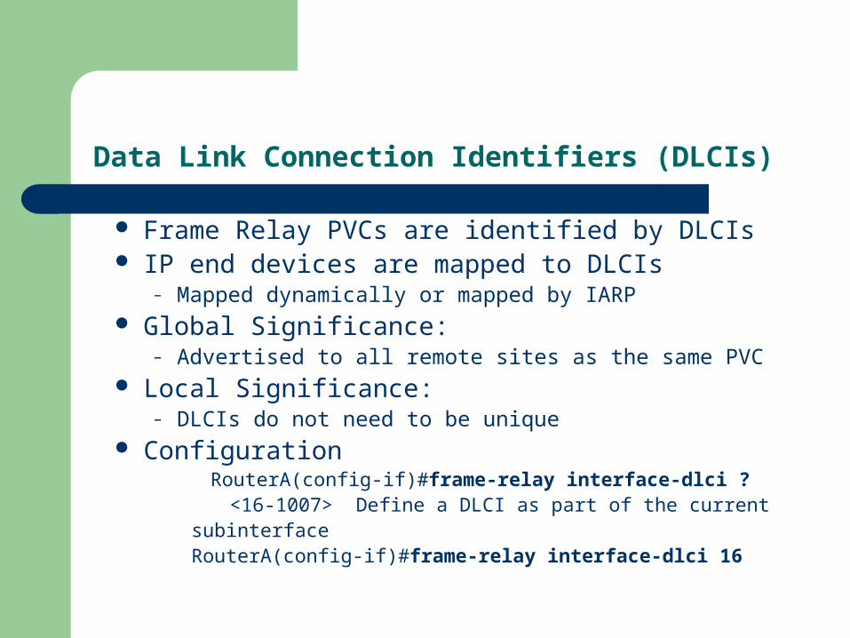
Data Link Connection Identifiers (DLCIs)
Frame Relay PVCs are identified by DLCIs IP end devices are mapped to DLCIs
– Mapped dynamically or mapped by IARP Global Significance:
– Advertised to all remote sites as the same PVC Local Significance:
– DLCIs do not need to be unique Configuration
RouterA(config-if)#frame-relay interface-dlci ?<16-1007> Define a DLCI as part of the current
subinterfaceRouterA(config-if)#frame-relay interface-dlci 16

Local Management Interface (LMI)
Background Purpose LMI Messages
– Keepalives– Multicasting– Multicast addressing– Status of virtual circuits
LMI Types
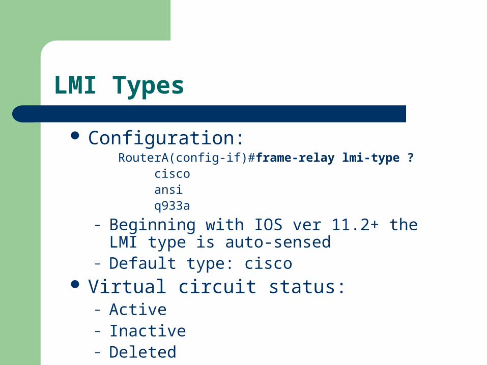
Configuration:RouterA(config-if)#frame-relay lmi-type ? cisco ansi q933a
– Beginning with IOS ver 11.2+ the LMI type is auto-sensed
– Default type: cisco Virtual circuit status:
– Active– Inactive– Deleted

Sub-interfaces
Definition– Multiple virtual circuits on a single serial
interface– Enables the assignment of different network-
layer characteristics to each sub-interface IP routing on one sub-interface IPX routing on another
– Mitigates difficulties associated with: Partial meshed Frame Relay networks Split Horizon protocols
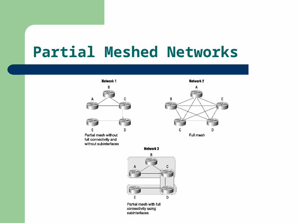
Partial Meshed Networks

Creating Sub-interfaces
Configuration:#1: Set the encapsulation on the serial interface
#2: Define the subinterfaceRouterA(config)#int s0
RouterA(config)#encapsulation frame-relay
RouterA(config)#int s0.?
<0-4294967295> Serial interface number
RouterA(config)#int s0.16 ?
multipoint Treat as a multipoint link
point-to-point Treat as a point-to-point link

Mapping Frame Relay
Necessary to IP end devices to communicate– Addresses must be mapped to the DLCIs– Methods:
Frame Relay map command Inverse-arp function
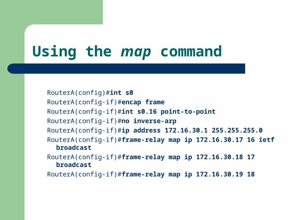
Using the map command
RouterA(config)#int s0
RouterA(config-if)#encap frame
RouterA(config-if)#int s0.16 point-to-point
RouterA(config-if)#no inverse-arp
RouterA(config-if)#ip address 172.16.30.1 255.255.255.0
RouterA(config-if)#frame-relay map ip 172.16.30.17 16 ietf broadcast
RouterA(config-if)#frame-relay map ip 172.16.30.18 17 broadcast
RouterA(config-if)#frame-relay map ip 172.16.30.19 18

Using the inverse arp command
RouterA(config)#int s0.16 point-to-point
RouterA(config-if)#encap frame-relay ietf
RouterA(config-if)#ip address 172.16.30.1 255.255.255.0

Congestion Control
Discard Eligibility (DE)
Forward-Explicit Congestion Notification (FECN)
Backward-Explicit Congestion Notification (BECN)

Committed Information Rate (CIR)
Definition: Provision allowing customers to purchase amounts of bandwidth lower than what they might need– Cost savings– Good for bursty traffic– Not good for constant amounts of data transmission

Monitoring Frame Relay
RouterA>sho frame ?
ip show frame relay IP statistics
lmi show frame relay lmi statistics
map Frame-Relay map table
pvc show frame relay pvc statistics
route show frame relay route
traffic Frame-Relay protocol statistics
RouterA#sho int s0
RouterB#show frame map
Router#debug frame-relay lmi
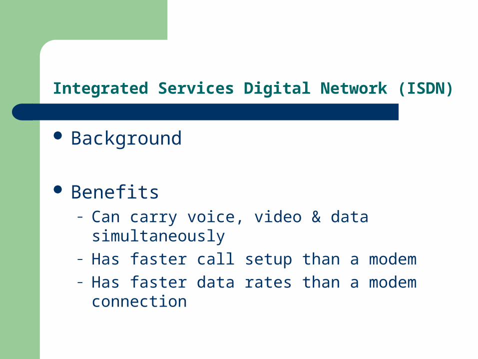
Integrated Services Digital Network (ISDN)
Background
Benefits– Can carry voice, video & data simultaneously– Has faster call setup than a modem– Has faster data rates than a modem connection
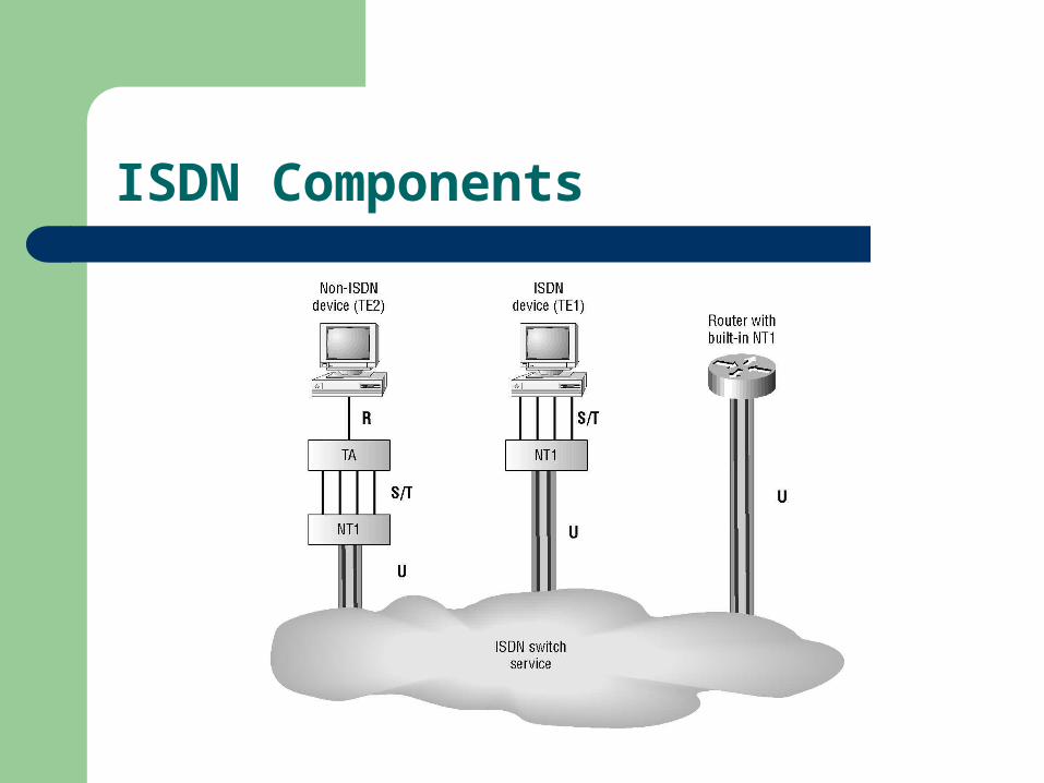
ISDN Components
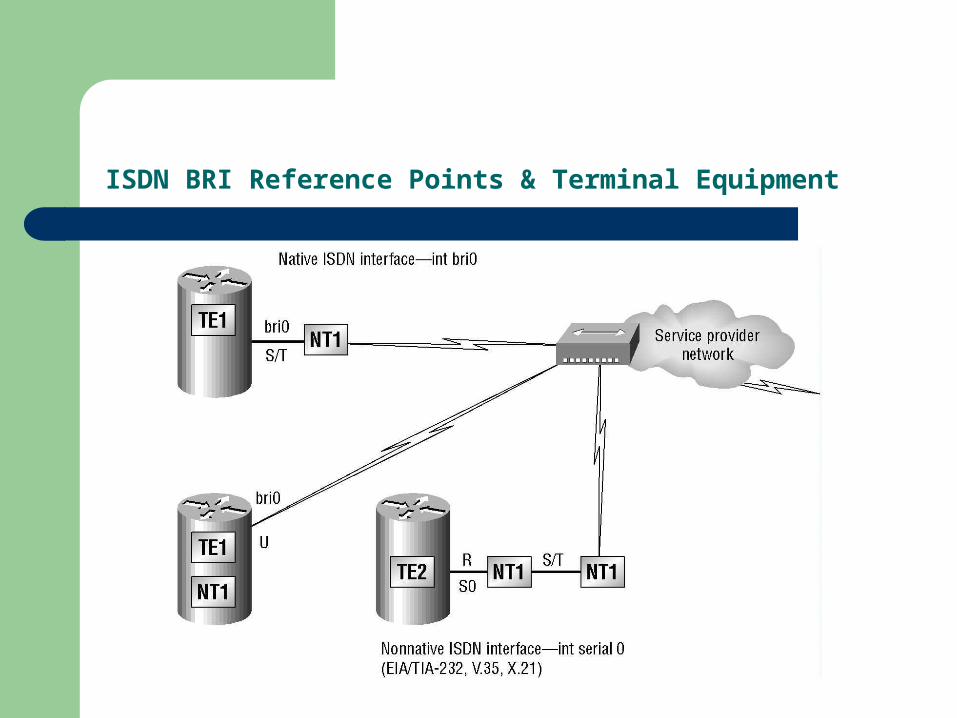
ISDN BRI Reference Points & Terminal Equipment
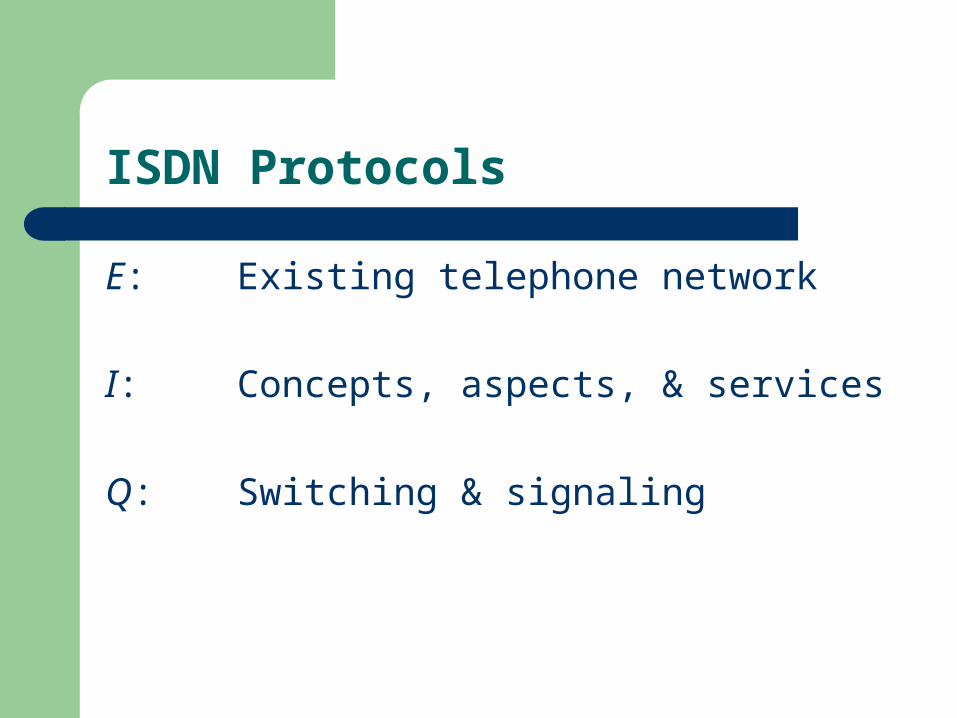
ISDN Protocols
E: Existing telephone network
I: Concepts, aspects, & services
Q: Switching & signaling
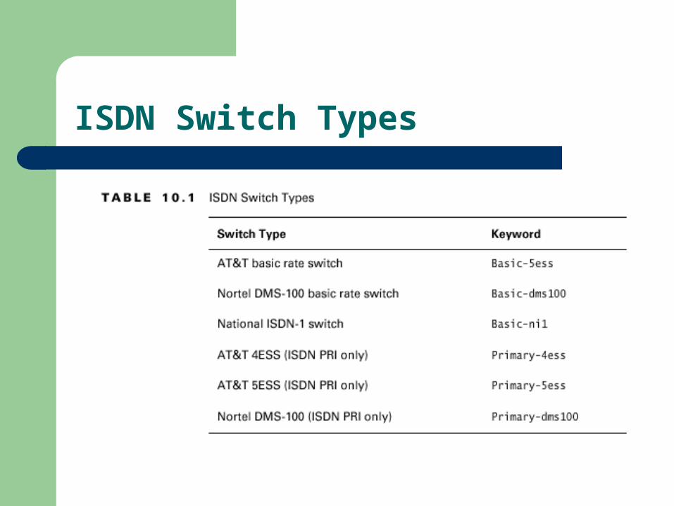
ISDN Switch Types

Basic Rate Interface (BRI)
2B+1D:– Two B-channels @ 64Kbps
Data
– One D-channel @ 16Kbps Control & signaling
Configuration:– SPIDs: one for each B-channel
~ telephone number of each B-channel

Primary Rate Interface (PRI)
23B+1D (North America)
– 23 B-channels @ 64 Kbps– 1 D-channel @ 64 Kbps
Total bit rate: >1.544 Mbps
Europe/Australia/etc….– 30 B-channels @ 64 Kbps– 1 D-channel @ 64 Kbps
Total bit rate: >2.048 Mbps

ISDN with Cisco Routers
Accessing ISDN:– Built-in NT1 (U reference point)
BRI interface– ISDN modem (TA)
Used with a router’s serial interface
RouterA#config t
Enter configuration commands, one per line. End with CTNL/Z.
RouterA(config)#isdn switch-type basic-ne1
RouterA(config)#int bri0
RouterA(config-if)#encap ppp (optional)
RouterA(config-if)#isdn spid1 085506610100 8650661
RouterA(config-if)#isdn spid2 085506620100 8650662

Dial-on-Demand Routing (DDR)
Allows 2 or more routers to dial an ISDN dial-up connection
– As-needed basis– Low-volume/periodic network connections– Reduces WAN costs– Works when packets meet requirements as “interesting traffic”

Configuring DDR
Tasks:#1: Define static routes
– How to get to remote networks– What interface to use
#2: Specify “interesting” traffic– Access Control List
#3: Configure the dialer information– Interface / IP address– Encapsulation– Linkage of ‘interesting traffic’– Telephone number
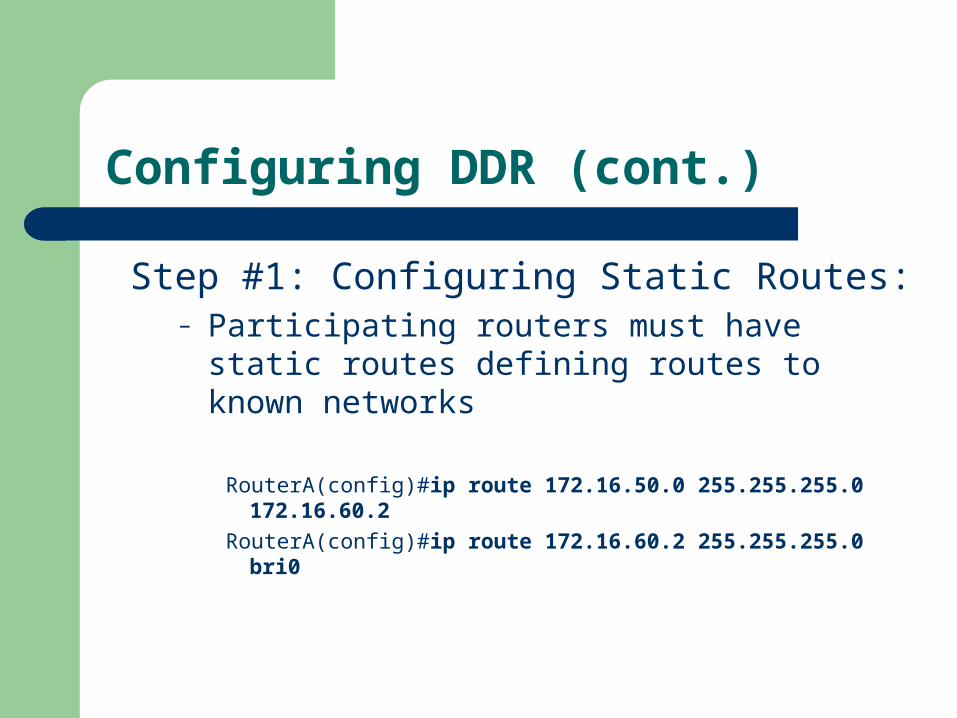
Configuring DDR (cont.)
Step #1: Configuring Static Routes:– Participating routers must have static routes
defining routes to known networks
RouterA(config)#ip route 172.16.50.0 255.255.255.0 172.16.60.2
RouterA(config)#ip route 172.16.60.2 255.255.255.0 bri0
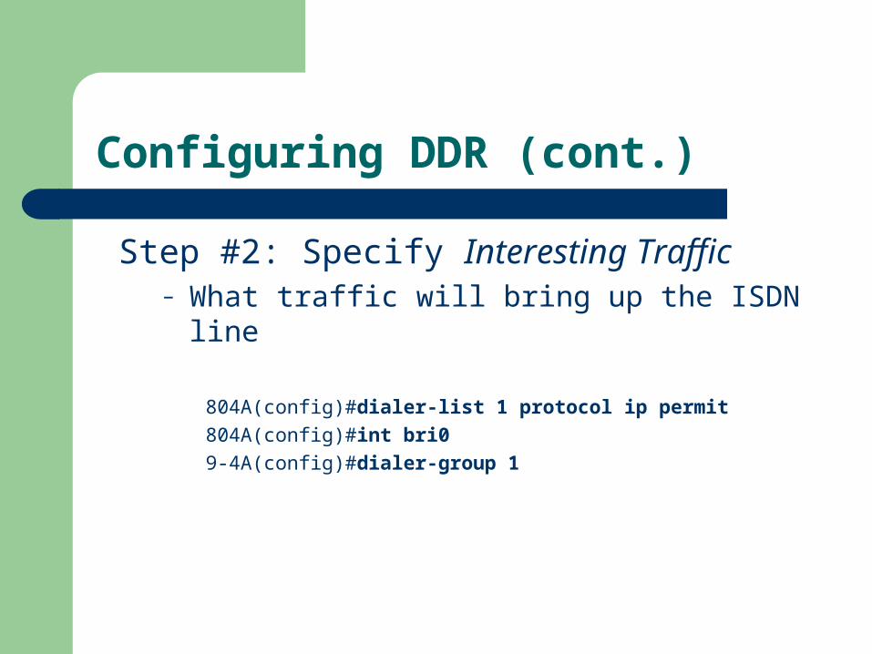
Configuring DDR (cont.)
Step #2: Specify Interesting Traffic– What traffic will bring up the ISDN line
804A(config)#dialer-list 1 protocol ip permit
804A(config)#int bri0
9-4A(config)#dialer-group 1
Configuring DDR (cont.)
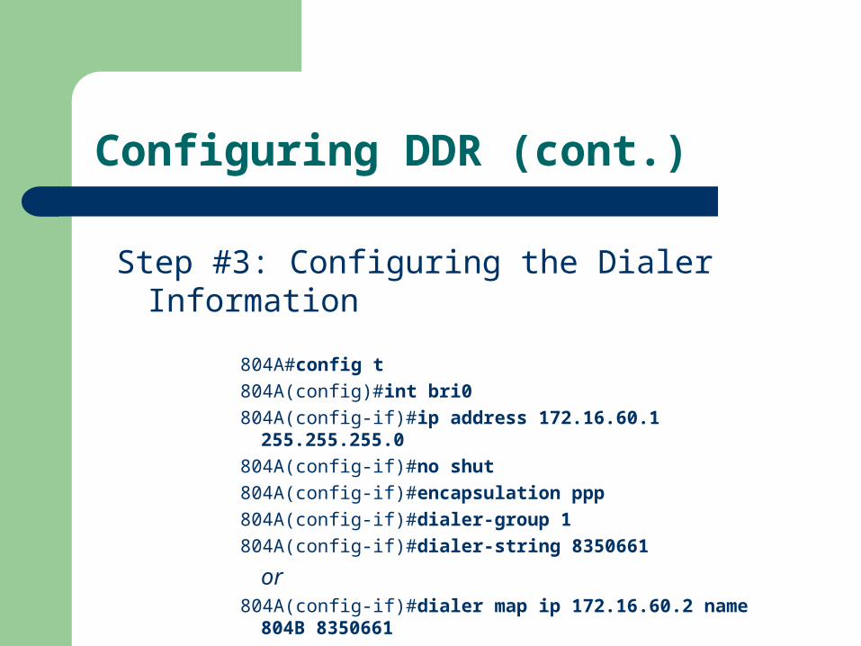
Step #3: Configuring the Dialer Information
804A#config t
804A(config)#int bri0
804A(config-if)#ip address 172.16.60.1 255.255.255.0
804A(config-if)#no shut
804A(config-if)#encapsulation ppp
804A(config-if)#dialer-group 1
804A(config-if)#dialer-string 8350661
or804A(config-if)#dialer map ip 172.16.60.2 name 804B
8350661

DDR with Access Lists
Use extended access lists to be more specific about what is interesting traffic…
804A(config)#dialer-list 1 list 110804A(config)#access-list 110 permit tcp any any eq smtp804A(config)#access-list 110 permit tcp any any eq telnet804A(config)#int bri0804A(config-if)#dialer-group 1

Verifying the ISDN Operation
ping & telnet show dialer show isdn active show isdn status show ip route debug isdn q921 debug isdn q931 debug dialer isdn disconnect int bri0

Summary
Identified PPP operations to encapsulate WAN data on Cisco routers
Configured authentication with PPP Stated how Frame Relay works on a large WAN
network Configured Frame Relay LMIs, maps, and
subinterfaces Monitored Frame Relay operation in the router Stated the ISDN protocols, function groups, and
reference points Described how Cisco implements ISDN BRI