atlas tdaq dataflow page 1 atlas tdaq roib manual atlas tdaq dataflow roi builder manual document...
TRANSCRIPT
ATLAS
page 1
ATLAS TDAQ RoIB Manual
ATLAS TDAQ DATAFLOW
RoI Builder Manual Document Version: 3 Document Issue: 6 Document ID: ATLAS-TDAQ-2004-XXX Document Date: 22/2/05 Document Status:
Abstract
This report describes the ATLAS Region of Interest Builder (RoIB) and documents tests done to validate correct operation of the first boards produced for the Region of Interest Builder system. Tests were performed at Argonne and integrations with the MIROD and L1Calo systems were subsequently performed in the H8 area at CERN. Initial indications are that the system design is sound and will perform as expected. System details are documented here.
Keywords: list of keywords
Institutes and Authors:
Argonne National Laboratory: R. E. Blair, John Dawson, Gary Drake, William Haberichter, James Schlereth
Michigan State University: Maris Abolins, Yuri Ermoline, Bernard Pope
ATL-DQ-ON-0005

ATLAS TDAQ RoIB Manual
Version/Issue: 3/6
page 2�
ATLAS TDAQ RoIB Manual
Table 1 Document Change Record
Title: ATLAS TDAQ RoIB Manual
ID: ATLAS-TDAQ-2004-XXX
Version Issue Date Comment
3 3 20/11/04 Initial draft for distribution to authors
3 4 22/2/05 Updated figure 1 so it would not be misleading
3 6 7/12/05 Updated document info and checked in to edms
Introduction
The first run of Region of Interest Builder components have been produced and tested. In order to make the system more accessible to the full collaboration we have set down here some of the details of the components and their functional and operational characteristics.
Purpose of the document
This document is intended to describe most components of the Region of Interest Builder and to provide adequate detail for experts to exploit the features of this system.
Glossary, acronyms and abbreviations
Glossary
Term Definition
S-Link Serial link system used for ATLAS readout
Acronyms and Abbreviations Acronym/Abbreviation Definition
AU Assembly Unit
EAB Extended Array Buffer
EL1ID Extended Level 1 ID
FPGA Field Programmable Gate Array
HLT High Level Trigger
LDC Link Destination Card
RAM Random Access Memory
RoI Region of Interest
RoIB Region of Interest Builder
TTC Timing, Trigger and Control
TTCRX TTC receiver chip

RoIB Manual ATLAS TDAQ
Version/Issue: 3/6
page 3
ATLAS TDAQ RoIB Manual
Acronym/Abbreviation Definition
VME Versa Module Europa
References
1 ATLAS High Level Triggers, DAQ and DCS Technical Proposal at http://atlasinfo.cern.ch/Atlas/GROUPS/DAQTRIG/SG/TP/tp_doc.html 2 S-Link documentation available at http://hsi.web.cern.ch/HSI/s-link/ 3Specification of the LVL1 / LVL2 trigger interface at https://edms.cern.ch/document/107485/1 4 ROIB Requirements at http://atlasinfo.cern.ch/Atlas/GROUPS/DAQTRIG/DataFlow/DataCollection/docs/DC-014.pdf 5 ATLAS Second Level Trigger Prototype RoI Builder design document at http://edms.cern.ch/document/367638/2.0
General Description
The ATLAS trigger uses information from the hardware based Level 1 system to guide the retrieval of information from the readout system for the next level trigger. Jet, electromagnetic, tau clusters, missing Et, total Et, total jet Et and muon candidate information from Level 1 determine Regions of Interest (RoIs) that seed further trigger decisions. This document describes the device that collects this data from the first level trigger.
System Overview
Figure 1: The RoIB components and context.

ATLAS TDAQ RoIB Manual
Version/Issue: 3/6
page 4�
ATLAS TDAQ RoIB Manual
The Region of Interest Builder (RoIB) for the ATLAS High Level Trigger (HLT) is a VMEbus based system designed to collect data from the Level 1 trigger and assemble the data fragments into a complete record of the Level 1 decision. This data is passed via S-Link to the Level 2 Supervisor Farm which makes this data available to the HLT. The system is comprised of input cards and builder cards. These cards are connected via a backplane that passes fragments form the input cards to the builder cards and passes flow control signals from the builder to the input cards. An over view of the system appears in Fig.1.
System Design
Input Cards
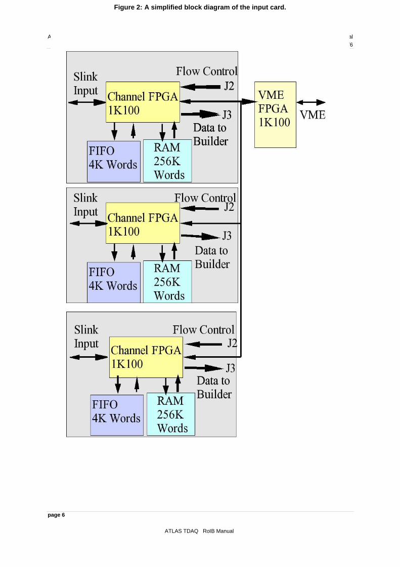
In the RoIB the ROI fragments are brought to Input cards of the RoIB via S-Link. Each Input card accommodates 3 input S-Link LDC‟s, and can service up to 8 RoIB cards (limited by the custom backplane). All transfer of information from the Input Cards to the RoIB cards is via J3 and a custom backplane mounted in the rear of the crate. Each Input card also has a diagnostic RAM initialized from VMEbus which allows an on-board diagnostic system to emulate Level 1 fragments, and enables the operator to verify the RoIB system in a stand alone mode. The diagnostic RAM‟s on the Input Cards are 256K words deep. The Input Cards have several modes of operation. By Diagnostic Mode we mean that the RoIB System performs its functions without any input from Level 1 Trigger Elements or from external devices emulating Level 1. Instead input data streams are provided by the diagnostic RAM‟s resident on the Input Cards. These RAM‟s are loaded from VMEbus in block transfers, and the contents may be data for diagnostic purposes (such as 5‟s and A‟s, shifting 1‟s or 0‟s, etc.), or may be test vectors from Monte Carlo or simulation results. For these purposes, the S-Link Supervisor output from the RoIB card could be routed via S-Link to a processor resident in the crate which would execute the diagnostic codes. We provide the capability to use this diagnostic RAM in an alternate mode, where instead of being written from the VMEbus, the RAM is written with Fragments from the incoming data stream from Level 1. The contents of the diagnostic RAM can then be accessed in block transfers from VMEbus, and the received Fragments can be examined for diagnostic or system monitoring purposes. This is referred to as Sniffer Mode. Data from an Input Card is transferred through the custom backplane to the RoIB Cards via J3, with the 3 channels functioning independently of each other. One channel is transferred on Row a, one on Row b, and one on Row c. Each word is transferred in 2 twenty bit pieces, one after the other on a 40 MHz clock. The first of the two 20 bit words consists of the lower 16 bits of the data words, enable bit which is active for valid data, control bit which is always inactive, top word which is always inactive, and clock. The second of the two 20 bit words consists of the upper 16 bits of the data words, enable bit which is always active for valid data, control bit which is active for “control” words and inactive for “data” words, top word which is always active, and clock. The data is passed from each of the 3 channels of the input card via the custom backplane to the RoIB Cards in parallel and received by each of them where the half words are concatenated and the fragment is reconstructed. Because the system is capable of accommodating 12 input S-Link channels high density 250 pin connectors are used on J3 of the RoIB Cards, with the 10 extra pins tied to ground. The flow control signals are transferred via User Defined pins on J2. Since each RoIB Card deals with input from 12 S-Link channels, it must provide 12 flow control signals. These 12 signal lines are bussed on J2 and are wire-or‟ed. The first three of the flow control signals go to the first Input Card, the second three go to the second Input Card, etc. See Table 2 for the pin assignments. A simplified block diagram of the Input Card is shown in Fig. 2. There is an FPGA to handle the transactions with VME, which include 32 bit non-privileged transfers for reading/writing registers and 64 bit block transfers for reading/writing the diagnostic RAM(S). The VME FPGA also includes a number of registers, such as status, which are relevant to all three channels. The Input Card supports three input
RoIB Manual ATLAS TDAQ
Version/Issue: 3/6
page 5
ATLAS TDAQ RoIB Manual
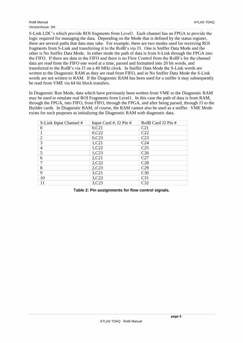
S-Link LDC‟s which provide ROI fragments from Level1. Each channel has an FPGA to provide the logic required for managing the data. Depending on the Mode that is defined by the status register, there are several paths that data may take. For example, there are two modes used for receiving ROI fragments from S-Link and transferring it to the RoIB‟s via J3. One is Sniffer Data Mode and the other is No Sniffer Data Mode, In either mode the path of data is from S-Link through the FPGA into the FIFO. If there are data in the FIFO and there is no Flow Control from the RoIB‟s for the channel data are read from the FIFO one word at a time, parsed and formatted into 20 bit words, and transferred to the RoIB‟s via J3 on a 40 MHz clock. In Sniffer Data Mode the S-Link words are written to the Diagnostic RAM as they are read from FIFO, and in No Sniffer Data Mode the S-Link words are not written to RAM. If the Diagnostic RAM has been used for a sniffer it may subsequently be read from VME via 64 bit block transfers. In Diagnostic Run Mode, data which have previously been written from VME to the Diagnostic RAM may be used to emulate real ROI Fragments from Level1. In this case the path of data is from RAM, through the FPGA, into FIFO, from FIFO, through the FPGA, and after being parsed, through J3 to the Builder cards. In Diagnostic RAM, of course, the RAM cannot also be used as a sniffer. VME Mode exists for such purposes as initializing the Diagnostic RAM with diagnostic data.
S-Link Input Channel # Input Card #, J2 Pin # RoIB Card J2 Pin # 0 0,C21 C21 1 0,C22 C22 2 0,C23 C23 3 1,C21 C24 4 1,C22 C25 5 1,C23 C26 6 2,C21 C27 7 2,C22 C28 8 2,C23 C29 9 3,C21 C30 10 3,C22 C31 11 3,C23 C32
Table 2: Pin assignments for flow control signals.
ATLAS TDAQ RoIB Manual
Version/Issue: 3/6
page 6�
ATLAS TDAQ RoIB Manual
Figure 2: A simplified block diagram of the input card.

RoIB Manual ATLAS TDAQ
Version/Issue: 3/6
page 7
ATLAS TDAQ RoIB Manual
TTC/LDC
We have developed a mezzanine card for bringing TTC into the RoIB system. This card appears to an Input card to be an S-Link LDC, but instead receives input from the TTC fiber into a TTCRX. The TTC information is latched on every Level One Accept, and is formatted on the mezzanine card to resemble an ROI fragment, and is accepted and processed by the RoIB as if it were an ROI fragment. The data which are latched on a Level One Accept is the 24 bits of Event Counter, 12 bits of Bunch Counter, and 8 bits of Trigger Type. When the data have been latched, they are reformatted in the form of an ROI Fragment, and written to a FIFO configured in the FPGA EAB‟s. If there is no Flow Control, the pseudo fragment is then transferred to the Input Card through the S-Link port. An 8 bit register internally in the FPGA is incremented on Event Resets to provide the top 8 bits of the Level One Event number.
Pseudo Fragment Word Number and Type Word 1 Control hxB0F00000 2 Data hx99123499 3 Data hx00000000 4 Data hx02040000 5 Data hx00008100 6 Data hx00000001 7 Data 32 bit Event Number 8 Data hx00000, 12 bit Bunch Crossing Number 9 Data hx000000, 8 bit Trigger Type 10 Data hx00000000 11 Data hx00000000 12 Data hx00000000 13 Data hx00000000 14 Control hxE0F00000
Table 3: Description of TTC/LDC Pseudo Fragment.
Builder Cards
Each fragment contains ROI data collected from a portion of the Level 1 trigger system. The Level 1 information required for the Level 2 system is the concatenation of all such fragments for an event. This includes both the information about the trigger decision as well as eta and phi data for the subsystems that cause an event trigger. We refer to the collected ROI fragments for a given event as an ROI record, and to the subsytem on the RoIB card that builds the record, as the Assembly Unit (AU). The Input cards pass ROI fragments to a set of RoIB cards. Each RoIB card communicates ROI records to four Supervisor processors. The compiled ROI RECORD is transferred to the target Supervisor processors using S-Link (see figure 1). Each of the RoIB cards is responsible for a subset of the events that trigger Level 1. Fig. 3 shows a simplified block diagram of the Builder card.

ATLAS TDAQ RoIB Manual
Version/Issue: 3/6
page 8�
ATLAS TDAQ RoIB Manual
In this RoIB there is a basic round robin algorithm. The system is expandable in units of four Supervisor processors by adding another RoIB card. The backplane is able to accommodate eight RoIB cards. Each RoIB card has registers which tell it which of the Level 1 channels are active, how many RoIB cards there are, which card it is in the ordering, etc.
Figure 3: Simplified block diagram of the builder card.

RoIB Manual ATLAS TDAQ
Version/Issue: 3/6
page 9
ATLAS TDAQ RoIB Manual
The event allocation algorithm must treat flow control properly and must deal with timeouts. A timeout may occur as the result of a tardy fragment or a missing fragment. The logic must distinguish the cases, and deal with either case The events are allocated to Supervisor processors on a round robin basis, with the hardware dealing automatically with the number of cards, number of Supervisor processors, etc. If the S-Link channel to a Supervisor processor is asserting flow control and flow control has backed up through the AU, the event discarded. The firmware also allows the allocation of events to specific AU‟s based on criteria other that the EL1ID, for example the Event Type. Each RoIB card is more or less autonomous. Events are allocated to RoIB cards on the basis of Mod(L1ID, # of cards). In every case the timeout system must interact with the event selection algorithm so that if a fragment is missing the problem is handled properly. It is essential that the system be able to function in the presence of flow control. It is not easy to build records arriving from a multiplicity of sources when flow control is going on and off from various elements, but it is important that the data integrity not be affected. We have deep FIFO's on every input so that the peaks of data activity are averaged, but have flow control going back via the individual S-Link channels to the Level 1 sources. Flow control exists at a number of points on the RoIB, and is not treated as one continuous signal. For example, when a fragment is received on the RoIB in the input buffer FIFO for that particular input, Flow Control is activated by each RoIB in the crate back to the Input Card which provided that input. The allocation algorithm immediately examines the L1ID and determines if the fragment is to be built in a record on this card. If not, Flow Control to the Input Card is released immediately. If the allocation algorithm determines that this is the proper card, it then determines which of the four builders on the card should build this record, and the logic begins to shift the fragment into that Builder FIFO assuming it is not currently building a previous record. When the trailer has been received by the builder FIFO the Flow Control back to the Input Card is released. Because Flow Control is wire-or‟ed on the backplane the Input Card continues to see Flow Control for this particular input until the fragment is contained in the appropriate builder FIFO. At that time another fragment corresponding to the same input can be shifted to the RoIB‟s. An exception to the this scenario is if the builder selected by the allocation algorithm is currently building a previous record so that the input buffer FIFO cannot shift its fragment into the builder FIFO, so it waits and as a consequence Flow Control continues to be exerted back to the input card. This particular input channel is then stopped and can not proceed until this particular Builder FIFO is empty, which will not happen until the previous record times out or is completed and shift out to the output FIFO. Another example of Flow Control on the RoIB is when the output FIFO goes half full, it exerts flow control back to the builder logic. This typically happens while a record is being transferred into the output FIFO, and in that case the current record will be transferred in its entirety, but no other records will be transferred to that output FIFO until it is no longer half full. An output FIFO begins transferring data to its S-Link port as soon as it is non-empty assuming Flow Control is not active on the S-Link. If the output FIFO goes half-full then the most likely cause is that the target processor is not servicing the S-Link. A likely reason for this is that the target processor has crashed, so that the Flow Control will not be released. In the case that Flow Control is being exerted by the output S-Link and the output FIFO for that output is half full, no further records will be allocated to that channel. The individual ROI fragments can be as long as 128 S-Link words including headers and trailers, and are in the S-Link format (see the L1/L2Document). This length constraint is imposed by the available EAB resources in the 20K200E FPGA‟s which we are using. It is necessary to accommodate the time skew of arriving fragments, and accordingly a timer is started at the arrival of the first fragment of each event. If all the fragments have been received before the timeout the compiled record will be transferred to the target Supervisor process. If the timeout occurs first the system transfers an incomplete record to the target Supervisor process. The timeout and other parameters are of course selectable from VMEbus. The maximum value of timeout that the system can implement is a critical parameter. To the extent that a partially built ROI record has to wait for fragments, the RoIB card must provide buffering so that other records can be built concurrently. The RoIB will accommodate a timeout as long as 1ms, but it should be understood that this places a severe strain on the hardware.

ATLAS TDAQ RoIB Manual
Version/Issue: 3/6
page 10�
ATLAS TDAQ RoIB Manual
Dealing with tardy fragments is a particularly vexing problem, and requires significant logic. If a fragment is lost, and an incomplete record is built, there can not be any later problems. However, if a fragment is tardy, an incomplete record is built, and the tardy fragment subsequently arrives, it is necessary that the logic recognize this fragment as having belonged to a previous event. As far as the implementation in hardware is concerned, it is much easier to use local information to reject these tardy fragments. We handle this problem by having the local allocation algorithm logic retain the EL1ID of the last complete record. The local logic knows if it has built an incomplete record, and how many incomplete records there have been since the last complete record, and so knows what EL1ID subsequent fragments must have to be valid. If a tardy fragment from a previous incompletely built record is received it is discarded. In the event that a fragment is received without a header, that fragment is ignored and treated as a missing fragment. Since the allocation algorithm uses the EL1ID as the basic data input, and the position in the frame of the fragment of the EL1ID is determined in relation to the header, the allocation algorithm cannot reliably function, so the fragment is ignored. If the trailer is missing, the partial fragment will be built into the record, but it will be evident to the supervisor processor that the fragment had an error. The input buffer on the RoIB card can contain 128 S-Link words. In the event that a Fragment is longer than 128 words the buffer will go full and the fragment will be truncated at the 128
th word. This truncation will be evident to the Supervisor Processor, but will not affect the
building of the relevant record. J3 Pin Numbers Data A1-A16 Channel 0 Data 0-15, Channel 0 Data 16-31 B1-B16 Channel 1 Data 0-15, Channel 1 Data 16-31 C1-C16 Channel 2 Data 0-15, Channel 2 Data 16-31 D1-D16 Channel 3 Data 0-15, Channel 3 Data 16-31 A18-A33 Channel 4 Data 0-15, Channel 4 Data 16-31 B18-B33 Channel 5 Data 0-15, Channel 5 Data 16-31 C18-C33 Channel 6 Data 0-15, Channel 6 Data 16-31 D18-D33 Channel 7 Data 0-15, Channel 7 Data 16-31 A35-A50 Channel 8 Data 0-15, Channel 8 Data 16-31 B35-B50 Channel 9 Data 0-15, Channel 9 Data 16-31 C35-C50 Channel 10 Data 0-15, Channel 10 Data 16-31 D35-D50 Channel 11 Data 0-15, Channel 11 Data 16-31 E1-E4 Channel 0 Enable*, Control*, Top Word, Clock E5-E8 Channel 1 Enable*, Control*, Top Word, Clock E9-E12 Channel 2 Enable*, Control*, Top Word, Clock E13-E16 Channel 3 Enable*, Control*, Top Word, Clock E18-E21 Channel 4 Enable*, Control*, Top Word, Clock E22-E25 Channel 5 Enable*, Control*, Top Word, Clock E26-E29 Channel 6 Enable*, Control*, Top Word, Clock E30-E33 Channel 7 Enable*, Control*, Top Word, Clock E35-E38 Channel 8 Enable*, Control*, Top Word, Clock E39-E42 Channel 9 Enable*, Control*, Top Word, Clock E43-E46 Channel 10 Enable*, Control*, Top Word,
Clock E47-E50 Channel 11 Enable*, Control*, Top Word,
Clock All Pins Row F, All Unused Pins Rows A-E Ground
Table 4: J3 Pin assignments for data transfers. Stars indicate an inverted signal.

RoIB Manual ATLAS TDAQ
Version/Issue: 3/6
page 11
ATLAS TDAQ RoIB Manual
Card Configuration and Control
This section outlines the VME registers available for programming and controlling the two types of cards detailed above.
Input Card Registers and VME Address Map
The Input Card will respond to two types of address modifiers:
AM 09 – Extended non-privileged data access, A32/D32
AM 08 – Extended non-privileged 64-bit block transfers A32/d64
Geographical Address pins configure VME base address.
Address Offset
Register R/W Access Remarks
000000 Control/Status R/W LW DATA<10..0> see bit map 00000C Master Clear W LW Data-less function 000010 RAM Start Address<0> W LW DATA<17..0> 000014 RAM Start Address<1> W LW DATA<17..0> 000018 RAM Start Address<2> W LW DATA<17..0> 00001C RAM Start Address<0..2> W LW DATA<17..0> see note 000020 RAM Fragment Count<0> R/W LW DATA<15..0> 000024 RAM Fragment Count<1> R/W LW DATA<15..0> 000028 RAM Fragment Count<2> R/W LW DATA<15..0> 00002C RAM Fragment Count<0..2> R/W LW DATA<15..0> see note 000030 Diagnostic Start<0> W LW Data-less function 000034 Diagnostic Start<1> W LW Data-less function 000038 Diagnostic Start<2> W LW Data-less function 00003C Diagnostic Start<all> W LW Data-less function; see note 000040 Sniff RAM Word Count<0> R LW DATA<18..0> 000044 Sniff RAM Word Count<1> R LW DATA<18..0> 000048 Sniff RAM Word Count<2> R LW DATA<18..0> 000050 Sniff RAM Clear<0> W LW Data-less function 000054 Sniff RAM Clear<1> W LW Data-less function 000058 Sniff RAM Clear<2> W LW Data-less function 00005C Sniff RAM Clear<0..2> W LW Data-less function; see note 000060 FIFO Clear<0> W LW Data-less function 000064 FIFO Clear<1> W LW Data-less function 000068 FIFO Clear<2> W LW Data-less function 00006C FIFO Clear<0..2> W LW Data-less function; see note 000000 Diagnostic RAM<0> R/W MBLT DATA<34..0> see bit map 200000 Diagnostic RAM<1> R/W MBLT DATA<34..0> see bit map 400000 Diagnostic RAM<2> R/W MBLT DATA<34..0> see bit map 600000 Diagnostic RAM<0..2> W MBLT DATA<34..0> see bit map
Table 5: Input Card VME Address Map Summary
Diagnostic RAM and Sniff Data
Diagnostic Data can be written and Sniff Data can be read
D63 to D34 D33 D32 D31 to D0

ATLAS TDAQ RoIB Manual
Version/Issue: 3/6
page 12�
ATLAS TDAQ RoIB Manual
Unused S-Link Enable\ S-Link Control\ S-Link data
000000: RAM<0> Read and Write 64-bit MBLT access
200000: RAM<1> Read and Write 64-bit MBLT access
400000: RAM<2> Read and Write 64-bit MBLT access
600000: RAM<0..2> Write 64-bit MBLT access Diagnostic Data can be written to all three RAM at once
Control/Status
000000: Mode selection, Diagnostic Status, Standalone selection and Link reset Read and Write Long word access Bit R/W Function Comments 0 R/W Mode LSB „0‟=Standby, „1‟=VME, 1 R/W Mode „2‟=Diagnostic Run, 2 R/W Mode MSB „3‟=Sniff Data, „4‟=No Sniff Data 3 - Spare 4 R Diagnostic RAM 0 Event Done If „1‟ Diagnostic event is done 5 R Diagnostic RAM 1 Event Done If „1‟ Diagnostic event is done 6 R Diagnostic RAM 2 Event Done If „1‟ Diagnostic event is done 7 R/W Standalone If „1‟ Card will function alone 8 W S-Link reset Channel 0 When „1‟, self clearing 9 W S-Link reset Channel 1 When „1‟, self clearing 10 W S-Link reset Channel 2 When „1‟, self clearing

RoIB Manual ATLAS TDAQ
Version/Issue: 3/6
page 13
ATLAS TDAQ RoIB Manual
Diagnostic RAM<0>
Specify the starting address, fragment count for Diagnostic RAM <0> and start processing.
000010: RAM<0> Starting Address Write Long word access D31 to D18 D17 to D0 Unused Start Address
000020: RAM<0> Fragment count Read and Write Long word access D31 to D18 D15 to D0 Unused Fragment count
000030: RAM<0> Start processing Write Long word access
Diagnostic RAM<1>
Specify the starting address, fragment count for Diagnostic RAM <1> and start processing.
000014 RAM<1> Starting Address Write Long word access
000024: RAM<1> Fragment count Read and Write Long word access
000034: RAM<1> Start processing Write Long word access
Diagnostic RAM<2>
Specify the starting address, fragment count for Diagnostic RAM <2> and start processing.
000018: RAM<2> Starting Address Write Long word access
000028: RAM<2> Fragment count Read and Write Long word access
000038: RAM<2> Start processing Write Long word access
Diagnostic RAM<0..2>
The same function is performed on all three RAMs at once.
00001C: Starting Address for RAM<0..2> Write Long word access
00002C: Fragment count for RAM<0..2> Read and Write Long word access

ATLAS TDAQ RoIB Manual
Version/Issue: 3/6
page 14�
ATLAS TDAQ RoIB Manual
00003C: Start processing RAM<0..2> Write Long word access
Sniff RAM<0>
000040: Word Count for Sniff RAM<0> Read Long word access D31 to D19 D18 to D0 Unused Word count
000050: Clear word count and address registers for RAM<0> Write Long word access
Sniff RAM<1>
000044: Word Count for Sniff RAM<1> Read Long word access
000054: Clear word count and address registers for RAM<1> Write Long word access
Sniff RAM<2>
000048: Word Count for Sniff RAM<2> Read Long word access
000058: Clear word count and address registers for RAM<2> Write Long word access
Sniff RAM<0..2>
00005C: Clear word count and address registers for RAM<0..2> all at once. Write Long word access
FIFO Clear<0..2>
00006C: Clear the FIFO for all channels at once.

RoIB Manual ATLAS TDAQ
Version/Issue: 3/6
page 15
ATLAS TDAQ RoIB Manual
Builder Card Registers and VME Address Map
The Builder Card will respond to three types of address modifiers:
AM 09 – Extended non-privileged data access, A32/D32
AM 0B – Extended non-privileged 32-bit block transfers A32/D32
AM 08 – Extended non-privileged 64-bit block transfers A32/D64
Geographical Address pins configure VME base address. Address Offset
Register R/W Access Remarks
0000000 Control/Status Input<0..5> R/W LW See bit map 0000004 Histogram FIFO E/F Input<0..5> R LW See bit map 0000008 Input Data FIFO Empty Flags Input<0..5> R LW See bit map 0000010 Checksum FIFO Word Count Input<0,3> R LW See bit map 0000014 Checksum FIFO Word Count Input<1,4> R LR See bit map 0000018 Checksum FIFO Word Count Input<2,5> R LW See bit map 0000020 BCID/Trig type FIFO Word Count
Input<0,3> R LW See bit map
0000024 BCID/Trig type FIFO Word Count Input<1,4>
R LW See bit map
0000028 BCID/Trig type FIFO Word Count Input<2,5>
R LW See bit map
1000000 Control/Status Input<6..11> R/W LW See bit map 1000004 Histogram FIFO E/F Input<6..11> R LW See bit map 1000008 Input Data FIFO Empty Flags Input<6..11> R LW See bit map 1000010 Checksum FIFO Word Count Input<6,9> R LW See bit map 1000014 Checksum FIFO Word Count Input<7,10> R LW See bit map 1000018 Checksum FIFO Word Count Input<8,11> R LW See bit map 1000020 BCID/Trig type FIFO Word Count
Input<6,9> R LW See bit map
1000024 BCID/Trig type FIFO Word Count Input<7,10>
R LW See bit map
1000028 BCID/Trig type FIFO Word Count Input<8,11>
R LW See bit map
2000000 Checksum Error FIFO Input<0,3,6,9> R MBLT See bit map 2008000 Checksum Error FIFO Input<1,4,7,10> R MBLT See bit map 2010000 Checksum Error FIFO Input<2,5,8,11> R MBLT See bit map
2018000 BCID/Trig type Histogram FIFO Input<0,3,6,9>
R MBLT See bit map
2020000 BCID/Trig type Histogram FIFO Input<1,4,7,10>
R MBLT See bit map
2028000 BCID/Trig type Histogram FIFO Input<2,5,8,11>
R MBLT See bit map
2000030 Clear Histogram FIFO Inputs<0..11> W LW Data-less function 3000000 Ready Time FIFO Input<0,1>Output<0> R BLT See bit map 3000200 Ready Time FIFO Input<2,3>Output<0> R BLT See bit map 3000400 Ready Time FIFO Input<4,5>Output<0> R BLT See bit map 3000600 Ready Time FIFO Input<6,7>Output<0> R BLT See bit map 3000800 Ready Time FIFO Input<8,9>Output<0> R BLT See bit map 3000A00 Ready Time FIFO Input<10,11>Output<0> R BLT See bit map 3001000 Ready Time FIFO Input<0,1>Output<1> R BLT See bit map 3001200 Ready Time FIFO Input<2,3>Output<1> R BLT See bit map 3001400 Ready Time FIFO Input<4,5>Output<1> R BLT See bit map 3001600 Ready Time FIFO Input<6,7>Output<1> R BLT See bit map 3001800 Ready Time FIFO Input<8,9>Output<1> R BLT See bit map

ATLAS TDAQ RoIB Manual
Version/Issue: 3/6
page 16�
ATLAS TDAQ RoIB Manual
Address Offset
Register R/W Access Remarks
3001A00 Ready Time FIFO Input<10,11>Output<1> R BLT See bit map 3002000 Ready Time FIFO Input<0,1>Output<2> R BLT See bit map 3002200 Ready Time FIFO Input<2,3>Output<2> R BLT See bit map 3002400 Ready Time FIFO Input<4,5>Output<2> R BLT See bit map 3002600 Ready Time FIFO Input<6,7>Output<2> R BLT See bit map 3002800 Ready Time FIFO Input<8,9>Output<2> R BLT See bit map 3002A00 Ready Time FIFO Input<10,11>Output<2> R BLT See bit map 3003000 Ready Time FIFO Input<0,1>Output<3> R BLT See bit map 3003200 Ready Time FIFO Input<2,3>Output<3> R BLT See bit map 3003400 Ready Time FIFO Input<4,5>Output<3> R BLT See bit map 3003600 Ready Time FIFO Input<6,7>Output<3> R BLT See bit map 3003800 Ready Time FIFO Input<8,9>Output<3> R BLT See bit map 3003A00 Ready Time FIFO Input<10,11>Output<3> R BLT See bit map 3000000 Card ID/Card Count R/W LW See bit map 3000004 Active Channel R/W LW DATA<16..0> 3000008 Ready Time FIFO Enable R/W LW DATA<3..0> 3000010 Maximum Wait Time Output<0> R/W LW DATA<31..0> 3000014 Maximum Wait Time Output<1> R/W LW DATA<31..0> 3000018 Maximum Wait Time Output<2> R/W LW DATA<31..0> 300001C Maximum Wait Time Output<3> R/W LW DATA<31..0> 3000020 Ready Time FIFO E/F Flags Output<0> R LW See bit map 3000024 Ready Time FIFO E/F Flags Output<1> R LW See bit map 3000028 Ready Time FIFO E/F Flags Output<2> R LW See bit map 300002C Ready Time FIFO E/F Flags Output<3> R LW See bit map 3000030 Ready Time FIFO Word Count
Input<0..3>Output<0> R LW See bit map
3000034 Ready Time FIFO Word Count Input<4.7>Output<0>
R LW See bit map
3000038 Ready Time FIFO Word Count Input<8.11>Output<0>
R LW See bit map
3000040 Ready Time FIFO Word Count Input<0..3>Output<1>
R LW See bit map
3000044 Ready Time FIFO Word Count Input<4.7>Output<0>
R LW See bit map
3000048 Ready Time FIFO Word Count Input<8.11>Output<1>
R LW See bit map
3000050 Ready Time FIFO Word Count Input<0..3>Output<2>
R LW See bit map
3000054 Ready Time FIFO Word Count Input<4.7>Output<2>
R LW See bit map
3000058 Ready Time FIFO Word Count Input<8.11>Output<2>
R LW See bit map
3000060 Ready Time FIFO Word Count Input<0..3>Output<3>
R LW See bit map
3000064 Ready Time FIFO Word Count Input<4.7>Output<3>
R LW See bit map
3000068 Ready Time FIFO Word Count Input<8.11>Output<3>
R LW See bit map
3000070 Ready Time FIFO Clear Output<0> W LW Data-less function 3000074 Ready Time FIFO Clear Output<1> W LW Data-less function 3000078 Ready Time FIFO Clear Output<2> W LW Data-less function 300007C Ready Time FIFO Clear Output<3> W LW Data-less function 4000000 Spy FIFO Output<0> R MBLT DATA<32..0>

RoIB Manual ATLAS TDAQ
Version/Issue: 3/6
page 17
ATLAS TDAQ RoIB Manual
Address Offset
Register R/W Access Remarks
4008000 Spy FIFO Output<1> R MBLT DATA<32..0> 4010000 Spy FIFO Output<2> R MBLT DATA<32..0> 4018000 Spy FIFO Output<3> R MBLT DATA<32..0> 4000000 Spy FIFO Enable R/W LW See bit map 4000004 Master Clear W LW Data-less function 4000008 Output Data FIFO Empty/Half Full Flags R LW See bit map 4000010 Spy FIFO Word Count Output<0> R LW DATA<12..0> 4000014 Spy FIFO Word Count Output<1> R LW DATA<12..0> 4000018 Spy FIFO Word Count Output<2> R LW DATA<12..0> 400001C Spy FIFO Word Count Output<3> R LW DATA<12..0> 4000020 Data FIFO Clear Output<0> W LW Data-less function 4000024 Data FIFO Clear Output<1> W LW Data-less function 4000028 Data FIFO Clear Output<2> W LW Data-less function 400002C Data FIFO Clear Output<3> W LW Data-less function 4000030 Spy FIFO Clear Output<0> W LW Data-less function 4000034 Spy FIFO Clear Output<1> W LW Data-less function 4000038 Spy FIFO Clear Output<2> W LW Data-less function 400003C Spy FIFO Clear Output<3> W LW Data-less function
Table 6: Builder Card VME Address Map Summary.

ATLAS TDAQ RoIB Manual
Version/Issue: 3/6
page 18�
ATLAS TDAQ RoIB Manual
Control/Status
Enable Inputs, enable outputs, enable checksum error andhistogram FIFOs and select 24/32-bit Event ID.
0000000: Controls Inputs<0..5> Read and Write Long word access
Bit R/W Function Comments 0 R/W ID Word Size Input<0..2> „0‟=24-bit, „1‟=32-bit 1 R/W Channel Active Input<0) If „1‟ enabled 2 R/W Channel Active Input<1) If „1‟ enabled 3 R/W Channel Active Input<2) If „1‟ enabled 4 R/W Checksum FIFO Enable Input<0..2> If „1‟ enabled 5 R/W BCID/Trig Type FIFO Enable Input<0..2> If „1‟ enabled 6-7 - Spare 8 R/W Enable Input<0..2> Output<0> If „1‟ enabled 9 R/W Enable Input<0..2> Output<1> If „1‟ enabled 10 R/W Enable Input<0..2> Output<2> If „1‟ enabled 11 R/W Enable Input<0..2> Output<3> If „1‟ enabled 12-15 - Spare 16 R/W ID Word Size Input<3..5> „0‟=24-bit, „1‟=32-bit 17 R/W Channel Active Input<3) If „1‟ enabled 18 R/W Channel Active Input<4) If „1‟ enabled 19 R/W Channel Active Input<5) If „1‟ enabled 20 R/W Checksum FIFO Enable Input<3..5> If „1‟ enabled 21 R/W BCID/Trig Type FIFO Enable Input<3..5> If „1‟ enabled 22-23 - Spare 24 R/W Enable Input<3..5> Output<0> If „1‟ enabled 25 R/W Enable Input<3..5> Output<1> If „1‟ enabled 26 R/W Enable Input<3..5> Output<2> If „1‟ enabled 27 R/W Enable Input<3..5> Output<3> If „1‟ enabled 28-31 - Spare

RoIB Manual ATLAS TDAQ
Version/Issue: 3/6
page 19
ATLAS TDAQ RoIB Manual
1000000: Controls Inputs<6..11> Read and Write Long word access
Bit R/W Function Comments 0 R/W ID Word Size Input<6..8> „0‟=24-bit, „1‟=32-bit 1 R/W Channel Active Input<6) If „1‟ enabled 2 R/W Channel Active Input<7) If „1‟ enabled 3 R/W Channel Active Input<8) If „1‟ enabled 4 R/W Checksum FIFO Enable Input<6..8> If „1‟ enabled 5 R/W BCID/Trig Type FIFO Enable Input<6..8> If „1‟ enabled 6-7 - Spare 8 R/W Enable Input<6..8> Output<0> If „1‟ enabled 9 R/W Enable Input<6..8> Output<1> If „1‟ enabled 10 R/W Enable Input<6..8> Output<2> If „1‟ enabled 11 R/W Enable Input<6..8> Output<3> If „1‟ enabled 12-15 - Spare 16 R/W ID Word Size Input<9..11> „0‟=24-bit, „1‟=32-bit 17 R/W Channel Active Input<9) If „1‟ enabled 18 R/W Channel Active Input<10) If „1‟ enabled 19 R/W Channel Active Input<11) If „1‟ enabled 20 R/W Checksum FIFO Enable Input<9..11> If „1‟ enabled 21 R/W BCID/Trig Type FIFO Enable
Input<9..11> If „1‟ enabled
22-23 - Spare 24 R/W Enable Input<9..11> Output<0> If „1‟ enabled 25 R/W Enable Input<9..11> Output<1> If „1‟ enabled 26 R/W Enable Input<9..11> Output<2> If „1‟ enabled 27 R/W Enable Input<9..11> Output<3> If „1‟ enabled 28-31 - Spare

ATLAS TDAQ RoIB Manual
Version/Issue: 3/6
page 20�
ATLAS TDAQ RoIB Manual
Checksum Error and Histogram FIFO E/F Flags
Indicates the state of the Checksum Error and Histogram FIFOs, empty or full
0000004: Empty/Full flags for Input<0..5> Read Long word access Bit R/W Function Comments 0 R Checksum FIFO Empty Input<0> „1‟=empty 1 R BCID/Trig type FIFO Empty Input<0> „1‟=empty 2 R Checksum FIFO Empty Input<1> „1‟=empty 3 R BCID/Trig type FIFO Empty Input<1> „1‟=empty 4 R Checksum FIFO Empty Input<2> „1‟=empty 5 R BCID/Trig type FIFO Empty Input<2> „1‟=empty 6-7 - Spare 8 R Checksum FIFO Full Input<0> „1‟=full 9 R BCID/Trig type FIFO Full Input<0> „1‟=full 10 R Checksum FIFO Full Input<1> „1‟=full 11 R BCID/Trig type FIFO Full Input<1> „1‟=full 12 R Checksum FIFO Full Input<2> „1‟=full 13 R BCID/Trig type FIFO Full Input<2> „1‟=full 14-15 - Spare 16 R Checksum FIFO Empty Input<3> „1‟=empty 17 R BCID/Trig type FIFO Empty Input<3> „1‟=empty 18 R Checksum FIFO Empty Input<4> „1‟=empty 19 R BCID/Trig type FIFO Empty Input<4> „1‟=empty 20 R Checksum FIFO Empty Input<5> „1‟=empty 21 R BCID/Trig type FIFO Empty Input<5> „1‟=empty 22-23 - Spare 24 R Checksum FIFO Full Input<3> „1‟=full 25 R BCID/Trig type FIFO Full Input<3> „1‟=full 26 R Checksum FIFO Full Input<4> „1‟=full 27 R BCID/Trig type FIFO Full Input<4> „1‟=full 28 R Checksum FIFO Full Input<5> „1‟=full 29 R BCID/Trig type FIFO Full Input<5> „1‟=full 30-31 - Spare

RoIB Manual ATLAS TDAQ
Version/Issue: 3/6
page 21
ATLAS TDAQ RoIB Manual
1000004: Empty/Full flags for Input<6..11> Read Long word access
Bit R/W Function Comments 0 R Checksum FIFO Empty Input<6> „1‟=empty 1 R BCID/Trig type FIFO Empty Input<6> „1‟=empty 2 R Checksum FIFO Empty Input<7> „1‟=empty 3 R BCID/Trig type FIFO Empty Input<7> „1‟=empty 4 R Checksum FIFO Empty Input<8> „1‟=empty 5 R BCID/Trig type FIFO Empty Input<8> „1‟=empty 6-7 - Spare 8 R Checksum FIFO Full Input<6> „1‟=full 9 R BCID/Trig type FIFO Full Input<6> „1‟=full 10 R Checksum FIFO Full Input<7> „1‟=full 11 R BCID/Trig type FIFO Full Input<7> „1‟=full 12 R Checksum FIFO Full Input<8> „1‟=full 13 R BCID/Trig type FIFO Full Input<8> „1‟=full 14-15 - Spare 16 R Checksum FIFO Empty Input<9> „1‟=empty 17 R BCID/Trig type FIFO Empty Input<9> „1‟=empty 18 R Checksum FIFO Empty Input<10> „1‟=empty 19 R BCID/Trig type FIFO Empty Input<10> „1‟=empty 20 R Checksum FIFO Empty Input<11> „1‟=empty 21 R BCID/Trig type FIFO Empty Input<11> „1‟=empty 22-23 - Spare 24 R Checksum FIFO Full Input<9> „1‟=full 25 R BCID/Trig type FIFO Full Input<9> „1‟=full 26 R Checksum FIFO Full Input<10> „1‟=full 27 R BCID/Trig type FIFO Full Input<10> „1‟=full 28 R Checksum FIFO Full Input<11> „1‟=full 29 R BCID/Trig type FIFO Full Input<11> „1‟=full 30-31 - Spare

ATLAS TDAQ RoIB Manual
Version/Issue: 3/6
page 22�
ATLAS TDAQ RoIB Manual
Input Data FIFO Empty Flags
Indicates the state of the Input Data FIFOsl
0000008: Empty flags for Input<0..5>
Read Long word access
Bit R/W Function Comments 0 R Data FIFO Empty Input<0>Output<0> „1‟=empty 1 R Data FIFO Empty Input<0>Output<1> „1‟=empty 2 R Data FIFO Empty Input<0>Output<2> „1‟=empty 3 R Data FIFO Empty Input<0>Output<3> „1‟=empty 4 R Data FIFO Empty Input<1>Output<0> „1‟=empty 5 R Data FIFO Empty Input<1>Output<1> „1‟=empty 6 R Data FIFO Empty Input<1>Output<2> „1‟=empty 7 R Data FIFO Empty Input<1>Output<3> „1‟=empty 8 R Data FIFO Empty Input<2>Output<0> „1‟=empty 9 R Data FIFO Empty Input<2>Output<1> „1‟=empty 10 R Data FIFO Empty Input<2>Output<2> „1‟=empty 11 R Data FIFO Empty Input<2>Output<3> „1‟=empty 12 R Data FIFO Empty Input<0> „1‟=empty 13 R Data FIFO Empty Input<0> „1‟=empty 14 R Data FIFO Empty Input<0> „1‟=empty 15 - Spare 16 R Data FIFO Empty Input<3>Output<0> „1‟=empty 17 R Data FIFO Empty Input<3>Output<1> „1‟=empty 28 R Data FIFO Empty Input<3>Output<2> „1‟=empty 39 R Data FIFO Empty Input<3>Output<3> „1‟=empty 20 R Data FIFO Empty Input<4>Output<0> „1‟=empty 21 R Data FIFO Empty Input<4>Output<1> „1‟=empty 22 R Data FIFO Empty Input<4>Output<2> „1‟=empty 23 R Data FIFO Empty Input<4>Output<3> „1‟=empty 24 R Data FIFO Empty Input<5>Output<0> „1‟=empty 25 R Data FIFO Empty Input<5>Output<1> „1‟=empty 26 R Data FIFO Empty Input<5>Output<2> „1‟=empty 27 R Data FIFO Empty Input<5>Output<3> „1‟=empty 28 R Data FIFO Empty Input<3> „1‟=empty 29 R Data FIFO Empty Input<4> „1‟=empty 30 R Data FIFO Empty Input<5> „1‟=empty 31 - Spare
RoIB Manual ATLAS TDAQ
Version/Issue: 3/6
page 23
ATLAS TDAQ RoIB Manual
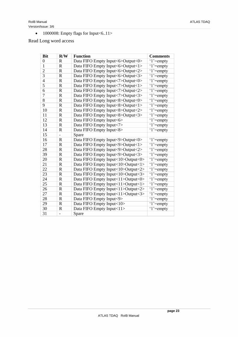
1000008: Empty flags for Input<6..11>
Read Long word access
Bit R/W Function Comments 0 R Data FIFO Empty Input<6>Output<0> „1‟=empty 1 R Data FIFO Empty Input<6>Output<1> „1‟=empty 2 R Data FIFO Empty Input<6>Output<2> „1‟=empty 3 R Data FIFO Empty Input<6>Output<3> „1‟=empty 4 R Data FIFO Empty Input<7>Output<0> „1‟=empty 5 R Data FIFO Empty Input<7>Output<1> „1‟=empty 6 R Data FIFO Empty Input<7>Output<2> „1‟=empty 7 R Data FIFO Empty Input<7>Output<3> „1‟=empty 8 R Data FIFO Empty Input<8>Output<0> „1‟=empty 9 R Data FIFO Empty Input<8>Output<1> „1‟=empty 10 R Data FIFO Empty Input<8>Output<2> „1‟=empty 11 R Data FIFO Empty Input<8>Output<3> „1‟=empty 12 R Data FIFO Empty Input<6> „1‟=empty 13 R Data FIFO Empty Input<7> „1‟=empty 14 R Data FIFO Empty Input<8> „1‟=empty 15 - Spare 16 R Data FIFO Empty Input<9>Output<0> „1‟=empty 17 R Data FIFO Empty Input<9>Output<1> „1‟=empty 28 R Data FIFO Empty Input<9>Output<2> „1‟=empty 39 R Data FIFO Empty Input<9>Output<3> „1‟=empty 20 R Data FIFO Empty Input<10>Output<0> „1‟=empty 21 R Data FIFO Empty Input<10>Output<1> „1‟=empty 22 R Data FIFO Empty Input<10>Output<2> „1‟=empty 23 R Data FIFO Empty Input<10>Output<3> „1‟=empty 24 R Data FIFO Empty Input<11>Output<0> „1‟=empty 25 R Data FIFO Empty Input<11>Output<1> „1‟=empty 26 R Data FIFO Empty Input<11>Output<2> „1‟=empty 27 R Data FIFO Empty Input<11>Output<3> „1‟=empty 28 R Data FIFO Empty Input<9> „1‟=empty 29 R Data FIFO Empty Input<10> „1‟=empty 30 R Data FIFO Empty Input<11> „1‟=empty 31 - Spare

ATLAS TDAQ RoIB Manual
Version/Issue: 3/6
page 24�
ATLAS TDAQ RoIB Manual
Checksum FIFO Word Count
Contains the FIFO word counts for the Checksum Histograms
0000010: Word counts for Input<0,3> Read Long word access
D31 to D25 D24 to D16 D15 to D9 D8 to D0 Unused Checksum FIFO Word Count
Input<3> Unused Checksum FIFO Word
Count Input<0>
0000014: Word counts for Input<1,4> Read Long word access
D31 to D25 D24 to D16 D15 to D9 D8 to D0 Unused Checksum FIFO Word
Count Input<4> Unused Checksum FIFO Word Count
Input<1>
0000018: Word counts for Input<2,5> Read Long word access
D31 to D25 D24 to D16 D15 to D9 D8 to D0 Unused Checksum FIFO Word
Count Input<5> Unused Checksum FIFO Word Count
Input<2>
1000010: Word counts for Input<6,9> Read Long word access
D31 to D25 D24 to D16 D15 to D9 D8 to D0 Unused Checksum FIFO Word
Count Input<9> Unused Checksum FIFO Word Count
Input<6>
1000014: Word counts for Input<7,10> Read Long word access
D31 to D25 D24 to D16 D15 to D9 D8 to D0 Unused Checksum FIFO Word
Count Input<10> Unused Checksum FIFO Word Count
Input<7>
1000018: Word counts for Input<8,11> Read Long word access
D31 to D25 D24 to D16 D15 to D9 D8 to D0 Unused Checksum FIFO Word
Count Input<11> Unused Checksum FIFO Word Count
Input<8>

RoIB Manual ATLAS TDAQ
Version/Issue: 3/6
page 25
ATLAS TDAQ RoIB Manual
BCID/Trigger Type FIFO Word Count
Contains the FIFO word counts for the BCID/BCID/Trig type Histograms
0000020: Word counts for Input<0,3> Read Long word access
D31 to D25 D24 to D16 D15 to D9 D8 to D0 Unused BCID/Trig type FIFO Word
Count Input<3> Unused BCID/Trig type FIFO Word
Count Input<0>
0000024: Word counts for Input<1,4> Read Long word access
D31 to D25 D24 to D16 D15 to D9 D8 to D0 Unused BCID/Trig type FIFO Word
Count Input<4> Unused BCID/Trig type FIFO Word
Count Input<1>
0000028: Word counts for Input<2,5> Read Long word access
D31 to D25 D24 to D16 D15 to D9 D8 to D0 Unused BCID/Trig type FIFO Word
Count Input<5> Unused BCID/Trig type FIFO Word
Count Input<2>
1000020: Word counts for Input<6,9> Read Long word access
D31 to D25 D24 to D16 D15 to D9 D8 to D0 Unused BCID/Trig type FIFO Word
Count Input<9> Unused BCID/Trig type FIFO Word
Count Input<6>
1000024: Word counts for Input<7,10> Read Long word access
D31 to D25 D24 to D16 D15 to D9 D8 to D0 Unused BCID/Trig type FIFO Word
Count Input<10> Unused BCID/Trig type FIFO Word
Count Input<7>
1000028: Word counts for Input<8,11> Read Long word access
D31 to D25 D24 to D16 D15 to D9 D8 to D0 Unused BCID/Trig type FIFO Word
Count Input<11> Unused BCID/Trig type FIFO Word
Count Input<8>
Checksum Error FIFO Data
2000000: Checksum Error FIFO Data Inputs<0,3,6,9> Read 64-bit MBLT access
D63 to D48 D47 to D32 D31 to D16 D15 to D0 Checksum Error L1ID Input<9>
Checksum Error L1ID Input<6>
Checksum Error L1ID Input<3>
Checksum Error L1ID Input<0>
2008000: Checksum Error FIFO Data Inputs<1,4,7,10>
ATLAS TDAQ RoIB Manual
Version/Issue: 3/6
page 26�
ATLAS TDAQ RoIB Manual
Read 64-bit MBLT access D63 to D48 D47 to D32 D31 to D16 D15 to D0 Checksum Error L1ID Input<10>
Checksum Error L1ID Input<7>
Checksum Error L1ID Input<4>
Checksum Error L1ID Input<1>
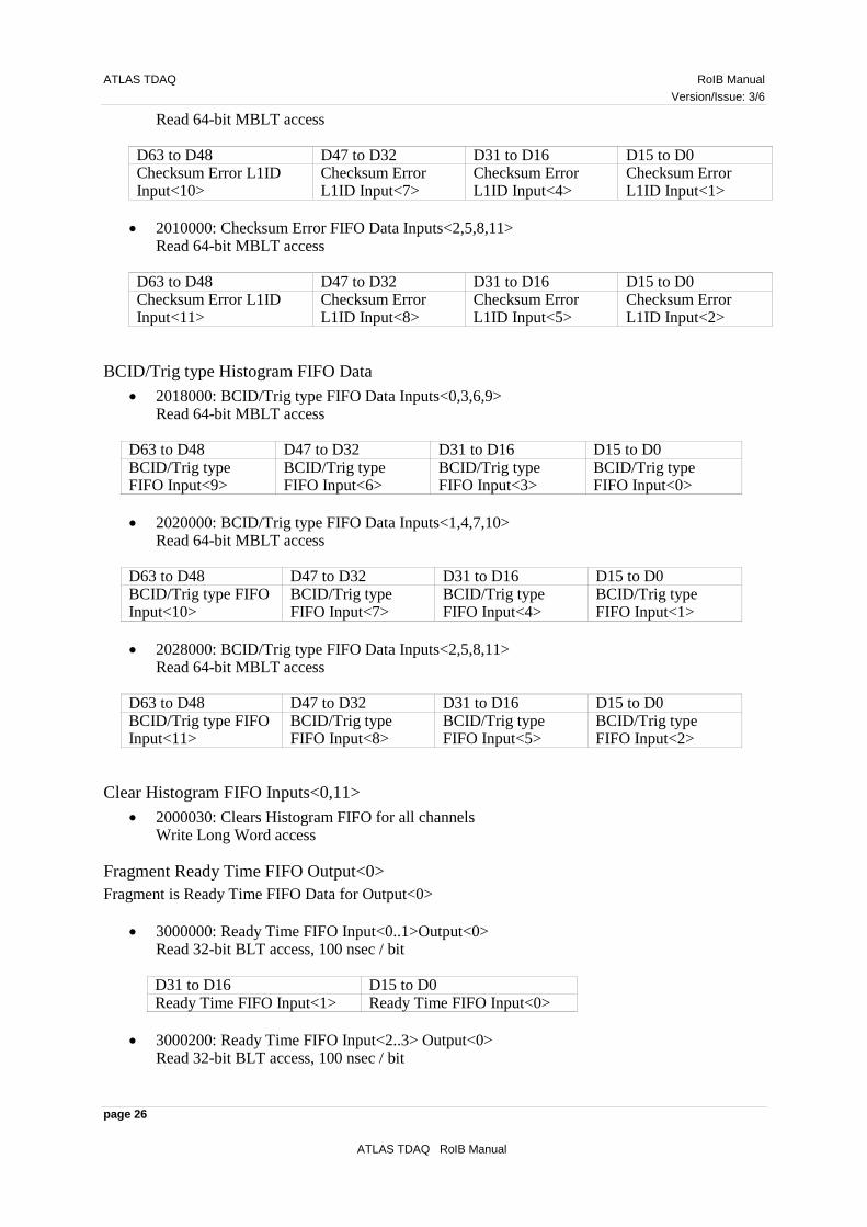
2010000: Checksum Error FIFO Data Inputs<2,5,8,11> Read 64-bit MBLT access
D63 to D48 D47 to D32 D31 to D16 D15 to D0 Checksum Error L1ID Input<11>
Checksum Error L1ID Input<8>
Checksum Error L1ID Input<5>
Checksum Error L1ID Input<2>
BCID/Trig type Histogram FIFO Data
2018000: BCID/Trig type FIFO Data Inputs<0,3,6,9> Read 64-bit MBLT access
D63 to D48 D47 to D32 D31 to D16 D15 to D0 BCID/Trig type FIFO Input<9>
BCID/Trig type FIFO Input<6>
BCID/Trig type FIFO Input<3>
BCID/Trig type FIFO Input<0>
2020000: BCID/Trig type FIFO Data Inputs<1,4,7,10> Read 64-bit MBLT access
D63 to D48 D47 to D32 D31 to D16 D15 to D0 BCID/Trig type FIFO Input<10>
BCID/Trig type FIFO Input<7>
BCID/Trig type FIFO Input<4>
BCID/Trig type FIFO Input<1>
2028000: BCID/Trig type FIFO Data Inputs<2,5,8,11> Read 64-bit MBLT access
D63 to D48 D47 to D32 D31 to D16 D15 to D0 BCID/Trig type FIFO Input<11>
BCID/Trig type FIFO Input<8>
BCID/Trig type FIFO Input<5>
BCID/Trig type FIFO Input<2>
Clear Histogram FIFO Inputs<0,11>
2000030: Clears Histogram FIFO for all channels Write Long Word access
Fragment Ready Time FIFO Output<0>
Fragment is Ready Time FIFO Data for Output<0>
3000000: Ready Time FIFO Input<0..1>Output<0> Read 32-bit BLT access, 100 nsec / bit D31 to D16 D15 to D0 Ready Time FIFO Input<1> Ready Time FIFO Input<0>
3000200: Ready Time FIFO Input<2..3> Output<0> Read 32-bit BLT access, 100 nsec / bit

RoIB Manual ATLAS TDAQ
Version/Issue: 3/6
page 27
ATLAS TDAQ RoIB Manual
D31 to D16 D15 to D0 Ready Time FIFO Input<3> Ready Time FIFO Input<2>
3000400: Ready Time FIFO Input<4..5> Output<0> Read 32-bit BLT access, 100 nsec / bit
D31 to D16 D15 to D0 Ready Time FIFO Input<5> Ready Time FIFO Input<4>
3000600: Ready Time FIFO Input<6..7> Output<0> Read 32-bit BLT access, 100 nsec / bit
D31 to D16 D15 to D0 Ready Time FIFO Input<7> Ready Time FIFO Input<6>
3000800: Ready Time FIFO Input<8..9> Output<0> Read 32-bit BLT access, 100 nsec / bit
D31 to D16 D15 to D0 Ready Time FIFO Input<9> Ready Time FIFO Input<8>
3000A00: Ready Time FIFO Input<10..11> Output<0> Read 32-bit BLT access, 100 nsec / bit
D31 to D16 D15 to D0 Ready Time FIFO Input<11> Ready Time FIFO Input<10>

ATLAS TDAQ RoIB Manual
Version/Issue: 3/6
page 28�
ATLAS TDAQ RoIB Manual
Fragment Ready Time FIFO Output<1>
Fragment is Ready Time FIFO Data for Output<1>
3001000: Ready Time FIFO Input<0..1>Output<1> Read 32-bit BLT access, 100 nsec / bit
3001200: Ready Time FIFO Input<2..3> Output<1> Read 32-bit BLT access, 100 nsec / bit
3001400: Ready Time FIFO Input<4..5> Output<1> Read 32-bit BLT access, 100 nsec / bit
3001600: Ready Time FIFO Input<6..7> Output<1> Read 32-bit BLT access, 100 nsec / bit
3001800: Ready Time FIFO Input<8..9> Output<1> Read 32-bit BLT access, 100 nsec / bit
3001A00: Ready Time FIFO Input<10..11> Output<1> Read 32-bit BLT access, 100 nsec / bit
Fragment Ready Time FIFO Output<2>
Fragment is Ready Time FIFO Data for Output<2>
3002000: Ready Time FIFO Input<0..1>Output<2> Read 32-bit BLT access, 100 nsec / bit
3002200: Ready Time FIFO Input<2..3> Output<2> Read 32-bit BLT access, 100 nsec / bit
3002400: Ready Time FIFO Input<4..5> Output<2> Read 32-bit BLT access, 100 nsec / bit
3002600: Ready Time FIFO Input<6..7> Output<2> Read 32-bit BLT access, 100 nsec / bit
3002800: Ready Time FIFO Input<8..9> Output<2> Read 32-bit BLT access, 100 nsec / bit
3002A00: Ready Time FIFO Input<10..11> Output<2> Read 32-bit BLT access, 100 nsec / bit
Fragment Ready Time FIFO Output<3>
Fragment is Ready Time FIFO Data for Output<3>
3003000: Ready Time FIFO Input<0..1>Output<3> Read 32-bit BLT access, 100 nsec / bit
3003200: Ready Time FIFO Input<2..3> Output<3> Read 32-bit BLT access, 100 nsec / bit

RoIB Manual ATLAS TDAQ
Version/Issue: 3/6
page 29
ATLAS TDAQ RoIB Manual
3003400: Ready Time FIFO Input<4..5> Output<3> Read 32-bit BLT access, 100 nsec / bit
3003600: Ready Time FIFO Input<6..7> Output<3> Read 32-bit BLT access, 100 nsec / bit
3003800: Ready Time FIFO Input<8..9> Output<3> Read 32-bit BLT access, 100 nsec / bit
3003A00: Ready Time FIFO Input<10..11> Output<3> Read 32-bit BLT access, 100 nsec / bit
Card ID / Card Count
Specifies the number of Builder cards in the system and the ID of this card
3000000: Read and Write Long word access D31 to D7 D6 to D4 D3 D2 to D0 Unused Card Count Unused Card ID
Active Input Channel
Specified the active Input channels and the Flow control state
3000004: Uses a bit mask to specify the active input channels Read and Write Long word access D31 to D17 D16 D15 to D12 D11 to D0 Unused Output Flow Control,
„1‟=active Unused Active Inputs,
„1‟=active
Ready Time FIFO Enable
Specifies the Output channels for which the ready Time FIFO is enabled
3000008: Uses a bit mask to specify the Output channels Read and Write Long word access
D31 to D4 D3 to D0 Unused Ready Time FIFO Enabled, Output<n>, „1‟=enabled
Maximum Wait Time
Specifies the maximum time to wait for all active input fragments to be ready
3000010: Wait time Output<0>, 25 nsec / bit. Read and Write Long word access
3000014: Wait time Output<1>, 25 nsec / bit. Read and Write Long word access
3000018: Wait time Output<2>, 25 nsec / bit. Read and Write Long word access
300001C: Wait time Output<3>, 25 nsec / bit. Read and Write Long word access
ATLAS TDAQ RoIB Manual
Version/Issue: 3/6
page 30�
ATLAS TDAQ RoIB Manual
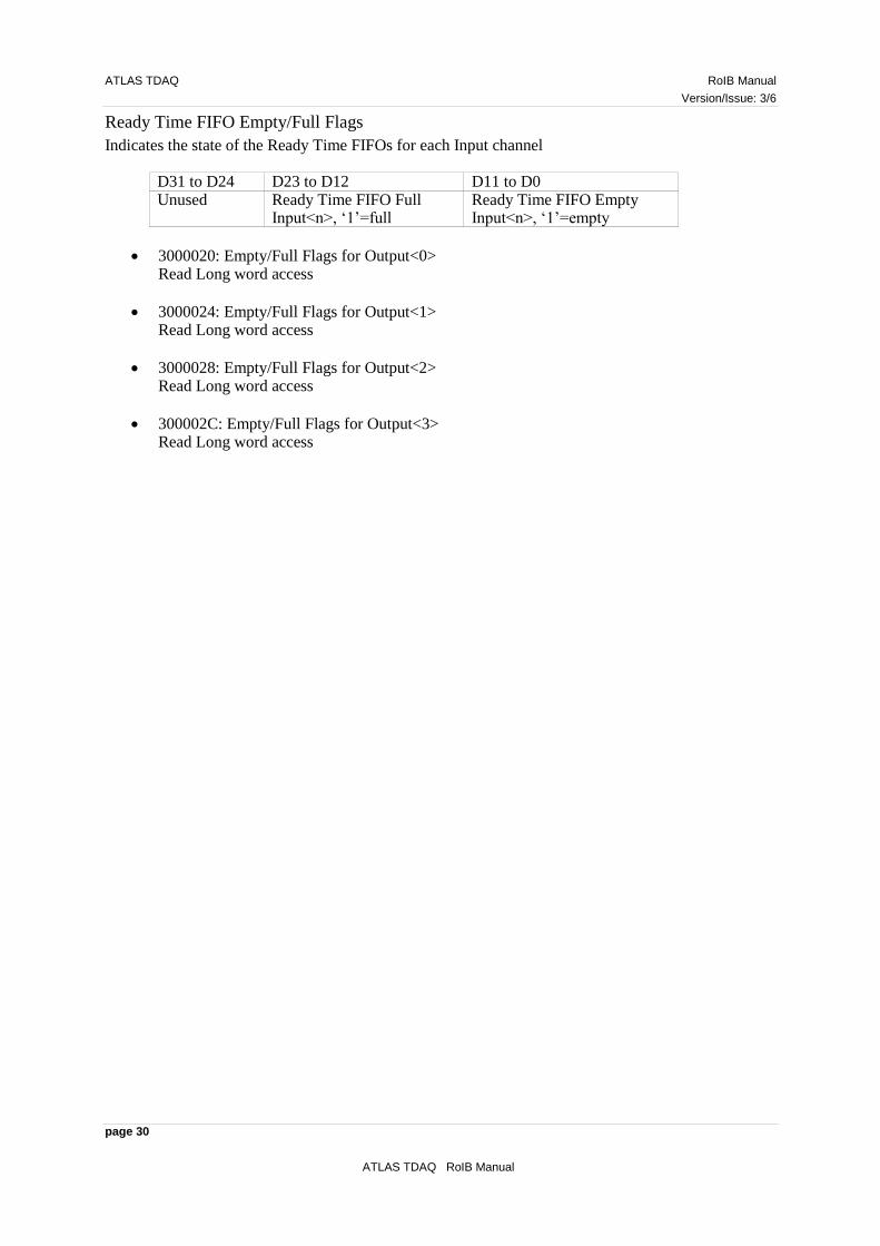
Ready Time FIFO Empty/Full Flags
Indicates the state of the Ready Time FIFOs for each Input channel
D31 to D24 D23 to D12 D11 to D0 Unused Ready Time FIFO Full
Input<n>, „1‟=full Ready Time FIFO Empty Input<n>, „1‟=empty
3000020: Empty/Full Flags for Output<0> Read Long word access
3000024: Empty/Full Flags for Output<1> Read Long word access
3000028: Empty/Full Flags for Output<2> Read Long word access
300002C: Empty/Full Flags for Output<3> Read Long word access

RoIB Manual ATLAS TDAQ
Version/Issue: 3/6
page 31
ATLAS TDAQ RoIB Manual
Ready Time FIFO Word Count Output<0>
Indicates the Fragment is Ready Time FIFO word count for Output<0.
3000030: FIFO Word Count for Input<0..3> Read Long word access D31 to D24 D23 to D16 D15 to D8 D7 to D0 FIFO Word Count Input<3>
FIFO Word Count Input<2>
FIFO Word Count Input<1>
FIFO Word Count Input<0>
3000034: FIFO Word Count for Input<4..7> Read Long word access D31 to D24 D23 to D16 D15 to D8 D7 to D0 FIFO Word Count Input<7>
FIFO Word Count Input<6>
FIFO Word Count Input<5>
FIFO Word Count Input<4>
3000038: FIFO Word Count for Input<8..11> Read Long word access
D31 to D24 D23 to D16 D15 to D8 D7 to D0 FIFO Word Count Input<11>
FIFO Word Count Input<10>
FIFO Word Count Input<9>
FIFO Word Count Input<8>
Ready Time FIFO Word Count Output<1>
Indicates the Fragment is Ready Time FIFO word count for Output<1.
3000040: FIFO Word Count for Input<0..3> Read Long word access
3000044: FIFO Word Count for Input<4..7> Read Long word access
3000048: FIFO Word Count for Input<8..11> Read Long word access
Ready Time FIFO Word Count Output<2>
Indicates the Fragment is Ready Time FIFO word count for Output<0.
3000050: FIFO Word Count for Input<0..3> Read Long word access
3000054: FIFO Word Count for Input<4..7> Read Long word access
3000058: FIFO Word Count for Input<8..11> Read Long word access

ATLAS TDAQ RoIB Manual
Version/Issue: 3/6
page 32�
ATLAS TDAQ RoIB Manual
Ready Time FIFO Word Count Output<3>
Indicates the Fragment is Ready Time FIFO word count for Output<3.
3000060: FIFO Word Count for Input<0..3> Read Long word access
3000064: FIFO Word Count for Input<4..7> Read Long word access
3000068: FIFO Word Count for Input<8..11> Read Long word access
Ready Time FIFO Clear
Clear the Fragment is Ready Time FIFOs.
3000070: Clear the ready Time FIFO for Output<0> Write Long word access
3000074: Clear the ready Time FIFO for Output<1> Write Long word access
3000078: Clear the ready Time FIFO for Output<2> Write Long word access
300007C: Clear the ready Time FIFO for Output<3> Write Long word access
RoIB Manual ATLAS TDAQ
Version/Issue: 3/6
page 33
ATLAS TDAQ RoIB Manual
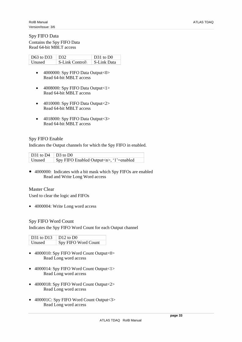
Spy FIFO Data
Contains the Spy FIFO Data Read 64-bit MBLT access D63 to D33 D32 D31 to D0 Unused S-Link Control\ S-Link Data
4000000: Spy FIFO Data Output<0> Read 64-bit MBLT access
4008000: Spy FIFO Data Output<1> Read 64-bit MBLT access
4010000: Spy FIFO Data Output<2> Read 64-bit MBLT access
4018000: Spy FIFO Data Output<3> Read 64-bit MBLT access
Spy FIFO Enable
Indicates the Output channels for which the Spy FIFO in enabled. D31 to D4 D3 to D0 Unused Spy FIFO Enabled Output<n>, „1‟=enabled
● 4000000: Indicates with a bit mask which Spy FIFOs are enabled Read and Write Long Word access
Master Clear
Used to clear the logic and FIFOs
● 4000004: Write Long word access
Spy FIFO Word Count
Indicates the Spy FIFO Word Count for each Output channel D31 to D13 D12 to D0 Unused Spy FIFO Word Count
● 4000010: Spy FIFO Word Count Output<0> Read Long word access
● 4000014: Spy FIFO Word Count Output<1> Read Long word access
● 4000018: Spy FIFO Word Count Output<2> Read Long word access
● 400001C: Spy FIFO Word Count Output<3> Read Long word access

ATLAS TDAQ RoIB Manual
Version/Issue: 3/6
page 34�
ATLAS TDAQ RoIB Manual
Data FIFO Clear
Used to clear the Data FIFOs for each Output channel
● 4000020: Clear the Data FIFO for Output<0> Write Long word access
● 4000024: Clear the Data FIFO for Output<1> Write Long word access
● 4000028: Clear the Data FIFO for Output<2> Write Long word access
● 400002c: Clear the Data FIFO for Output<3> Write Long word access
Spy FIFO Clear
Used to clear the Spy FIFOs for each Output channel
● 4000030: Clear the Spy FIFO for Output<0> Write Long word access
● 4000034: Clear the Spy FIFO for Output<1> Write Long word access
● 4000038: Clear the Spy FIFO for Output<2> Write Long word access
● 400003C: Clear the Spy FIFO for Output<3> Write Long word access
RoIB Manual ATLAS TDAQ
Version/Issue: 3/6
page 35
ATLAS TDAQ RoIB Manual
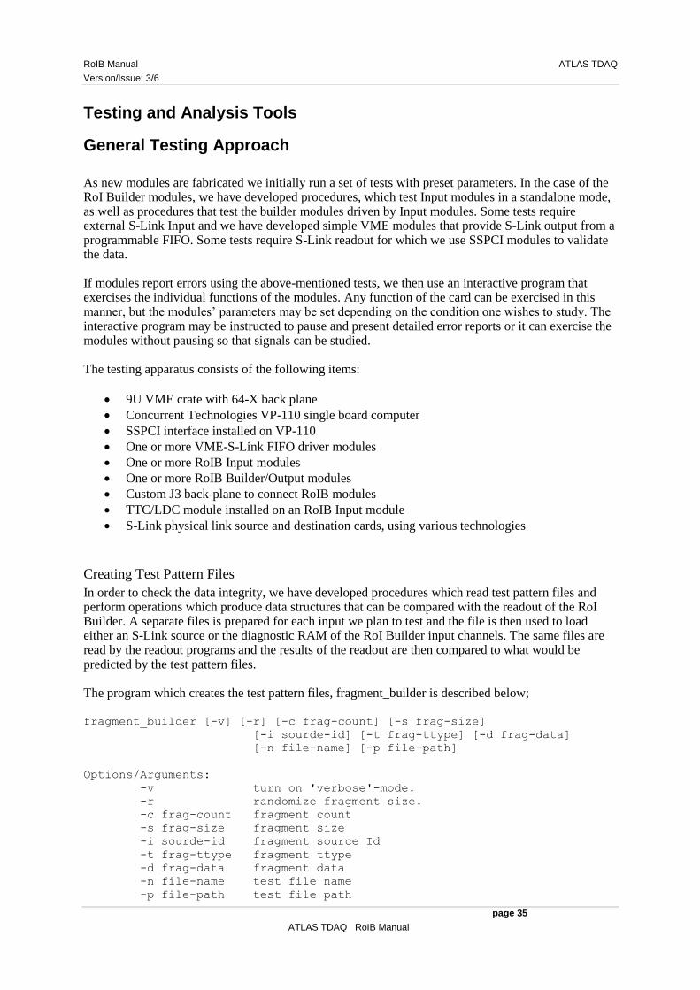
Testing and Analysis Tools
General Testing Approach
As new modules are fabricated we initially run a set of tests with preset parameters. In the case of the RoI Builder modules, we have developed procedures, which test Input modules in a standalone mode, as well as procedures that test the builder modules driven by Input modules. Some tests require external S-Link Input and we have developed simple VME modules that provide S-Link output from a programmable FIFO. Some tests require S-Link readout for which we use SSPCI modules to validate the data. If modules report errors using the above-mentioned tests, we then use an interactive program that exercises the individual functions of the modules. Any function of the card can be exercised in this manner, but the modules‟ parameters may be set depending on the condition one wishes to study. The interactive program may be instructed to pause and present detailed error reports or it can exercise the modules without pausing so that signals can be studied. The testing apparatus consists of the following items:
9U VME crate with 64-X back plane
Concurrent Technologies VP-110 single board computer
SSPCI interface installed on VP-110
One or more VME-S-Link FIFO driver modules
One or more RoIB Input modules
One or more RoIB Builder/Output modules
Custom J3 back-plane to connect RoIB modules
TTC/LDC module installed on an RoIB Input module
S-Link physical link source and destination cards, using various technologies
Creating Test Pattern Files
In order to check the data integrity, we have developed procedures which read test pattern files and perform operations which produce data structures that can be compared with the readout of the RoI Builder. A separate files is prepared for each input we plan to test and the file is then used to load either an S-Link source or the diagnostic RAM of the RoI Builder input channels. The same files are read by the readout programs and the results of the readout are then compared to what would be predicted by the test pattern files. The program which creates the test pattern files, fragment_builder is described below; fragment_builder [-v] [-r] [-c frag-count] [-s frag-size]
[-i sourde-id] [-t frag-ttype] [-d frag-data]
[-n file-name] [-p file-path]
Options/Arguments:
-v turn on 'verbose'-mode.
-r randomize fragment size.
-c frag-count fragment count
-s frag-size fragment size
-i sourde-id fragment source Id
-t frag-ttype fragment ttype
-d frag-data fragment data
-n file-name test file name
-p file-path test file path

ATLAS TDAQ RoIB Manual
Version/Issue: 3/6
page 36�
ATLAS TDAQ RoIB Manual
Description:
Builds a test data file of fragments of the requested size and type
Specific RoI Builder Tests
Input Module Sniff RAM Test
For this test we use the VME S-Link Emulators. Each port of the RoI Builder Input module to be tested is connected to an emulator. Currently the fragment_loader and test_sniffer programs, described below, must run on the same processor. test_sniffer [-v] [-g emul-slot] [-a active-in] [-p file-path]
[-c iter-count]
Options/Arguments:
-v turn on 'verbose'-mode.
-g input-slot geographical address of first input module
-a active-in active input mask
-p file-path test file path name
-c iter-count iteration count
Description:
Read the contents of Sniffer RAM and compares with data from test data
files. The test data files should be located in the directory specified by
the file-path, one file for each input port.
fragment_loader [-v] [-g emul-slot] [-a active-in] [-p file-path]
Options/Arguments:
-v turn on 'verbose'-mode.
-g emul-slot geographical address of first emulator
-a active-in active input mask
-p file-path test file path name
Description:
Reads files containing test data and loads the contents to VME
modules which send S-Link fragments to Input module ports. The test data
files are the same one as used by the test_sniffer program.
Builder Module Spy FIFO Test
For this test we use the Diagnostic RAM of the Input module as the data source and sample the data captured in the Spy FIFO of the Builder module. The test_roibspy program is described below. test_roibspy [-v] [-g i-slot] [-G o-slot] [-a active-in]
[-A active-out] [-p file-path] [-c iter_count]
Options/Arguments:
-v turn on 'verbose'-mode.
-g i-slot geographical address of first input module
-G o-slot geographical address of first output module
-a active-in active input mask
-A active-out active output mask

RoIB Manual ATLAS TDAQ
Version/Issue: 3/6
page 37
ATLAS TDAQ RoIB Manual
-p file-path test file path name
-c iter-count iteration count
Description:
Loads Diagnostic RAM with test data from files, clocks the data
through the RoI Builder, reads the Spy FIFO and compares with expected
results.
Builder Module S-Link Output Test
For this test we use the Diagnostic RAM of the Input module as the data source and capture the assembled events from one of the Output ports using an SSPCI module. This test exercises the flow control functions of both the Input and Output modules. The test_roibout program is described below. test_roibout [-v] [-g i-slot] [-G o-slot] [-a active-in]
[-A active-out] [-t tested-out] [-p file-path]
[-c iter_count]
Options/Arguments:
-v turn on 'verbose'-mode.
-g i-slot geographical address of first input module
-G o-slot geographical address of first builder module
-a active-in active input mask
-A active-out active output mask
-t tested-out tested output port
-p file-path test file path name
-c iter-count iteration count
Description:
Loads Diagnostic RAM with test data from files, clocks the data
through the RoI Builder, reads the selected Output port using an SSPCI
module and compares with expected results.

ATLAS TDAQ RoIB Manual
Version/Issue: 3/6
page 38�
ATLAS TDAQ RoIB Manual
Interactive ROI Builder Test
The interactive test program, roibtest, is menu driven and exercises the following functions: 1 - Configure
2 - Write Memory
3 - Read Memory
4 - Sniffer Run
5 - Spy Run
6 - Ready Times
7 - Histograms
8 - SLink Readout
Q – Quit
The Configure action allows one to change the number of modules and active channels, determine the data source set flow control options, have the test loop and pause and report errors. The Configure Menu is shown below 1 - Set Input Slot 19
2 - Active Inputs 7
3 - Set Output Slot 20
4 - Active Outputs 1
5 - Tested Output 0
6 - Ready Timeout 10000
D - Toggle Data Source Diagnostic
S - Toggle Standalone Off
F - Toggle FlowControl On
L - Toggle Looping On
P - Toggle PauseonError On
The current value of each option is listed at the right. The options are discussed below: · 1- Specifies the geographical address of the Input module being tested · 2 - Specifies a bit-mask of the input ports to be considered active · 3 - Specifies the geographical address of the Builder/Output module being tested. · 4 - Specifies a bit-mask of the output ports to be considered active. · 5 - Specifies the output port being tested when reading out with S-Link · 6 - Spcifies the maximum time, in usec, to wait for the last fragment to arrive when building events · D - Toggles the data source between S-Link and Diagnostic RAM · S - Toggles the Standalone mode of the Input module · F - Toggles the flow control function sent from the Builder to the Input module · L - Toggles between single pass and loop mode · P - Toggles between mode where program pauses when data errors are detected or continues to loop without reporting.
The Write Memory and Read Memory items of the main menu refer to the Diagnostic RAM of the Input module. Various patterns may be tested to check for bit errors. The Sniffer Run option performs a test of the Input module Sniffer RAM by executing the external program, fragment_loader, described in the previous section. This test can be made to loop and pause on errors. The Spy Run option performs a test of the Builder module Spy FIFO using either the Diagnostic RAM of the Input module external output provided by the fragment_loader program.

RoIB Manual ATLAS TDAQ
Version/Issue: 3/6
page 39
ATLAS TDAQ RoIB Manual
The options Ready Times and Histograms test the histogram functions of the Builder module. The raw data is displayed, but no error checking is performed. The S-Link Readout option runs a test where the selected Output port is read by an SSPCI module and checked for expected results. As in the case of the Spy Run, the data source may be either internal Diagnostic RAM or external S-Link controlled by the fragment_loader program.
Tests Using DVS
A number of tests have been implemented using sources and sinks which run on external PCs. To execute these multiple node tests, the Diagnostic Verification System has been exploited. Tests return a pass/fail result and may also create more detailed log files in case of errors. The tests are defined as having different complexity levels to DVS as follows:
● Level 1 – Spy FIFO test, involves only RoIB controller node
● Level 2 – S-Link output test, requires RoIB controller node plus one or mode nodes with FILAR device
● Level 3 – S-Link Input and S-Link output test, requires nodes used by Level 2 test as well as a third node with a QUEST device acting as data source.
Level 1 Test – test_roibspy
This program has been described above.
Level 2 Tests – run_roib and check_roibout
The second test builds on the first by reading out the assembled events into one to four S-Links. A FILAR was used to do the readout using the program check_roibout: check_roibout [-v] [-a active-in] [-A active-out]
[-t tested-out ...] [-p file-path] [-c iter-count]
[-f filar-chan ...]
Options/Arguments:
-v turn on 'verbose'-mode.
-a active-in active input bit-mask
-A active-out active output bit-mask
-t tested-out tested output ports
-p file-path test file path name
-c iter-count iteration count
-f filar-chan filar channels
Description:
Read the selected FILAR channel and compares with expected results
This program runs on a separate PC. A simple program, run_roib, was run on the RoIB controller, to load the diagnostic RAM and enable the desired channels. run_roib [-v] [-g i-slots ...] [-G o-slots ...] [-a active-in]
[-A active-out] [-p file-path] [-c iter-count]
Options/Arguments:
-v turn on 'verbose'-mode.
-g i-slots geographical address of input modules
-G o-slots geographical address of output modules
-a active-in active input bit-mask

ATLAS TDAQ RoIB Manual
Version/Issue: 3/6
page 40�
ATLAS TDAQ RoIB Manual
-A active-out active output bit-mask
-p file-path test file path name
-c iter-count iteration count
Description:
Runs external program that sends data from files to the Inputs,
clocks the data through the RoI Builder, reads the selected Output
port and compares with expected results
Various combinations of inputs may be tested. Output channels which are not readout may be enabled for some of the tests to validate the correct distribution of events.
Level 3 Tests – swroib_write, check_roibout and test_sampling
The third level of testing includes the S-Link input channels on the RoI Builder where a QUEST module was used to provide one to three sources of data. A program was developed to drive the channels with the same prepared data as had been loaded to diagnostic RAM for the second level test. The same program has been used to evaluate the performance of a PC based RoI Builder, thus the the name swroib_write, for SoftWare RoI Builder write. swroib_write [-v] [-a active-in] [-A active-out] [-c iter-count]
[-q qio-count] [-p file-path]
Options/Arguments:
-v turn on 'verbose'-mode.
-a active-in active input bit-mask
-A active-out active output bit-mask
-c iter-count iteration count
-q qio-count i/o's queuedbefore sending
-p file-path test file path name
Description:
Opens Qwest channels based on command line arguments, Distributes
fragments to active Qwest channels.
The RoI Builder is readout by check_roibout just as in the second level test. Running on the RoI Builder controller is a program called test_sampling, which in addition to enabling the desired channels, performs a monitoring function during the operation of the system. In particular, the monitoring includes reading the checksum error FIFO which detects any data errors as the data in transmitted through the system. test_sampling [-v] [-g i-slots ...] [-G o-slots ...] [-a active-in]
[-A active-out] [-c iter-count]
Options/Arguments:
-v turn on 'verbose'-mode.
-g i-slots geographical address of input modules
-G o-slots geographical address of output modules
-a active-in active input bit-mask
-A active-out active output bit-mask
-c iter-count iteration count
Description:
Sets the ROIBuilder modules to build events from selected inputs to
selected outputs and samples the FIFOs as the events are built
This test is run on a three node system with various combinitions of input and output channels.
RoIB Manual ATLAS TDAQ
Version/Issue: 3/6
page 41
ATLAS TDAQ RoIB Manual
This document has been prepared using parts of the Test Report Document Template version 0.2 provided and approved by the ATLAS TDAQ and DCS Connect Forum. For more information, go to http://atlas-connect-forum.web.cern.ch/Atlas-connect-forum/.
This template is based on the SDLT Single File Template that has been prepared by the IPT Group (Information, Process and Technology), IT Division, CERN (The European Laboratory for Particle Physics) and then converted to MS Word. For more information, go to http://framemaker.cern.ch/.