atex class files 1 magnetic levitation haptic … · stylus using stereoscopic vision so that they...
TRANSCRIPT

1077-2626 (c) 2017 IEEE. Translations and content mining are permitted for academic research only. Personal use is also permitted, but republication/redistribution requires IEEE permission. Seehttp://www.ieee.org/publications_standards/publications/rights/index.html for more information.
This article has been accepted for publication in a future issue of this journal, but has not been fully edited. Content may change prior to final publication. Citation information: DOI 10.1109/TVCG.2017.2772236, IEEETransactions on Visualization and Computer Graphics
JOURNAL OF LATEX CLASS FILES 1
Magnetic Levitation Haptic Augmentation forVirtual Tissue Stiffness Perception
Qianqian Tong, Zhiyong Yuan, Xiangyun Liao, Mianlun Zheng, Tianchen Yuan and Jianhui Zhao
Abstract—Haptic-based tissue stiffness perception is essential for palpation training system, which can provide the surgeon hapticcues for improving the diagnostic abilities. However, current haptic devices, such as Geomagic Touch, fail to provide immersive andnatural haptic interaction in virtual surgery due to the inherent mechanical friction, inertia, limited workspace and flawed hapticfeedback. To tackle this issue, we design a novel magnetic levitation haptic device based on electromagnetic principles to augment thetissue stiffness perception in virtual environment. Users can naturally interact with the virtual tissue by tracking the motion of magneticstylus using stereoscopic vision so that they can accurately sense the stiffness by the magnetic stylus, which moves in the magneticfield generated by our device. We propose the idea that the effective magnetic field (EMF) is closely related to the coil attitude for thefirst time. To fully harness the magnetic field and flexibly generate the specific magnetic field for obtaining required haptic perception,we adopt probability clouds to describe the requirement of interactive applications and put forward an algorithm to calculate the bestcoil attitude. Moreover, we design a control interface circuit and present a self-adaptive fuzzy proportion integration differentiation (PID)algorithm to precisely control the coil current. We evaluate our haptic device via a series of quantitative experiments which show thehigh consistency of the experimental and simulated magnetic flux density, the high accuracy (0.28mm) of real-time 3D positioning andtracking of the magnetic stylus, the low power consumption of the adjustable coil configuration, and the tissue stiffness perceptionaccuracy improvement by 2.38% with the self-adaptive fuzzy PID algorithm. We conduct a user study with 22 participants, and theresults suggest most of the users can clearly and immersively perceive different tissue stiffness and easily detect the tissueabnormality. Experimental results demonstrate that our magnetic levitation haptic device can provide accurate tissue stiffnessperception augmentation with natural and immersive haptic interaction.
Index Terms—Virtual tissue stiffness perception, magnetic levitation haptic feedback, surgical simulation, effective magnetic field
F
1 INTRODUCTION
HAPTIC feedback plays a key role in realizing realisticsurgical simulation in virtual environment [1], [2],
[3], which is usually performed for medical training, pre-operative planning, surgical performance evaluation, etc.Many medical procedures are often preceded or accompa-nied by palpation [4], which is usually used to examinemetastases, detect tissue abnormality, and locate anatomicallandmarks such as bones, muscles and pulse. It is beneficialfor performing these medical tasks by including palpationsin training simulators. Besides, stiffness perception is vitalfor performing palpations, and tissue stiffer than surround-ing could be recognized as a possible tumor [5]. Therefore,it is essential to accurately provide surgeons with tissuestiffness perception augmentation in surgical simulationsystems.
Currently, there are mainly two methods for augment-ing tissue stiffness perception: pseudo-haptic feedback andhaptic feedback. Pseudo-haptic feedback is based on tissuestiffness maps, which are provided by rolling mechanicalimaging [6], [7], [8], [9] and do not require real haptic
• Qianqian Tong, Zhiyong Yuan, Mianlun Zheng, Tianchen Yuan andJianhui Zhao are with School of Computer, Wuhan University, Wuhan,Hubei, China.E-mail: [email protected], [email protected], [email protected], [email protected], [email protected]
• Xiangyun Liao is with Shenzhen Key Laboratory of Virtual Realityand Human Interaction Technology, Shenzhen Institutes of AdvancedTechnology, Chinese Academy of Sciences, Shenzhen, China.E-mail: [email protected]
devices. Compared with pseudo-haptic feedback, hapticfeedback augments tissue stiffness perception by using ahaptic device to interact with virtual environments, whichis similar to the way of human perceiving information.
There have been numerous studies on tissue stiffnessperception augmentation using haptic devices. The mostwidely used haptic device is Geomagic Touch, such asPhantom Omni. Nisky et al. [10] combined a mechanicalsimulator with a Phantom Premium to perform the stiffnessperception in laparoscopy. Son et al. [11] utilized a Phantomas the master device to perceive soft tissue in teleoperationexperiments. Ullrich et al. [4] adopted two Phantom Omnidevices to implement a more realistic finger grip config-uration for palpation tasks by modifying the end effectorof one haptic device. However, Geomagic Touch provideshaptic feedback on the operation arm through the transferof mechanical joints. Such haptic devices suffer inherentmechanical friction and a certain amount of inertia, thus itwill raise an issue if the operation arm is moved quickly [12].Additionally, the stylus’ movement of such haptic devices islimited, thus the workspace is not large enough to simulatethe actual medical operation.
Another stream of haptic devices provide haptic feed-back in a contactless manner without direct skin contact,such as air-jet and ultrasonic radiation pressure [13]. TheAIREAL device, designed by Disney Research [14], is anexample of the air-jet haptic device, which can provideinteractive haptic feedback in mid-air by stimulating theuser’s skin with compressed air pressure fields. However,the transfer of the air-jet method through the medium is
1077-2626 (c) 2017 IEEE. Translations and content mining are permitted for academic research only. Personal use is also permitted, but republication/redistribution requires IEEE permission. Seehttp://www.ieee.org/publications_standards/publications/rights/index.html for more information.
This article has been accepted for publication in a future issue of this journal, but has not been fully edited. Content may change prior to final publication. Citation information: DOI 10.1109/TVCG.2017.2772236, IEEETransactions on Visualization and Computer Graphics
JOURNAL OF LATEX CLASS FILES 2
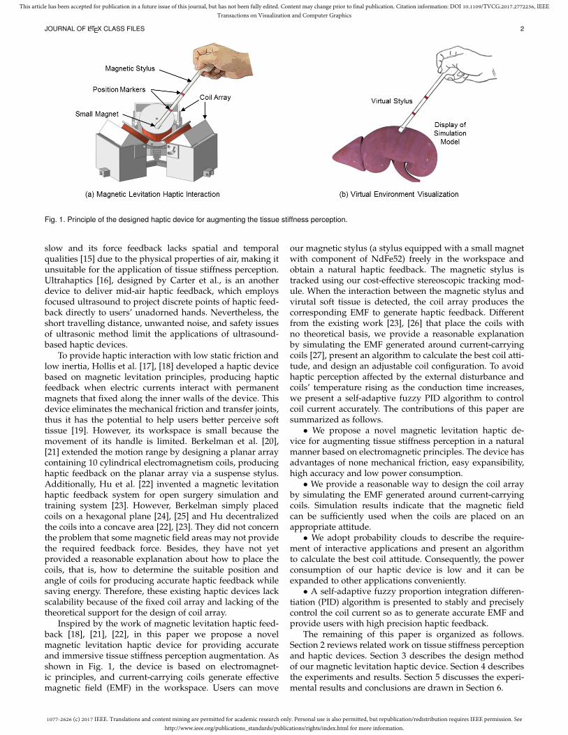
Fig. 1. Principle of the designed haptic device for augmenting the tissue stiffness perception.
slow and its force feedback lacks spatial and temporalqualities [15] due to the physical properties of air, making itunsuitable for the application of tissue stiffness perception.Ultrahaptics [16], designed by Carter et al., is an anotherdevice to deliver mid-air haptic feedback, which employsfocused ultrasound to project discrete points of haptic feed-back directly to users’ unadorned hands. Nevertheless, theshort travelling distance, unwanted noise, and safety issuesof ultrasonic method limit the applications of ultrasound-based haptic devices.
To provide haptic interaction with low static friction andlow inertia, Hollis et al. [17], [18] developed a haptic devicebased on magnetic levitation principles, producing hapticfeedback when electric currents interact with permanentmagnets that fixed along the inner walls of the device. Thisdevice eliminates the mechanical friction and transfer joints,thus it has the potential to help users better perceive softtissue [19]. However, its workspace is small because themovement of its handle is limited. Berkelman et al. [20],[21] extended the motion range by designing a planar arraycontaining 10 cylindrical electromagnetism coils, producinghaptic feedback on the planar array via a suspense stylus.Additionally, Hu et al. [22] invented a magnetic levitationhaptic feedback system for open surgery simulation andtraining system [23]. However, Berkelman simply placedcoils on a hexagonal plane [24], [25] and Hu decentralizedthe coils into a concave area [22], [23]. They did not concernthe problem that some magnetic field areas may not providethe required feedback force. Besides, they have not yetprovided a reasonable explanation about how to place thecoils, that is, how to determine the suitable position andangle of coils for producing accurate haptic feedback whilesaving energy. Therefore, these existing haptic devices lackscalability because of the fixed coil array and lacking of thetheoretical support for the design of coil array.
Inspired by the work of magnetic levitation haptic feed-back [18], [21], [22], in this paper we propose a novelmagnetic levitation haptic device for providing accurateand immersive tissue stiffness perception augmentation. Asshown in Fig. 1, the device is based on electromagnet-ic principles, and current-carrying coils generate effectivemagnetic field (EMF) in the workspace. Users can move
our magnetic stylus (a stylus equipped with a small magnetwith component of NdFe52) freely in the workspace andobtain a natural haptic feedback. The magnetic stylus istracked using our cost-effective stereoscopic tracking mod-ule. When the interaction between the magnetic stylus andvirutal soft tissue is detected, the coil array produces thecorresponding EMF to generate haptic feedback. Differentfrom the existing work [23], [26] that place the coils withno theoretical basis, we provide a reasonable explanationby simulating the EMF generated around current-carryingcoils [27], present an algorithm to calculate the best coil atti-tude, and design an adjustable coil configuration. To avoidhaptic perception affected by the external disturbance andcoils’ temperature rising as the conduction time increases,we present a self-adaptive fuzzy PID algorithm to controlcoil current accurately. The contributions of this paper aresummarized as follows.• We propose a novel magnetic levitation haptic de-
vice for augmenting tissue stiffness perception in a naturalmanner based on electromagnetic principles. The device hasadvantages of none mechanical friction, easy expansibility,high accuracy and low power consumption.• We provide a reasonable way to design the coil array
by simulating the EMF generated around current-carryingcoils. Simulation results indicate that the magnetic fieldcan be sufficiently used when the coils are placed on anappropriate attitude.• We adopt probability clouds to describe the require-
ment of interactive applications and present an algorithmto calculate the best coil attitude. Consequently, the powerconsumption of our haptic device is low and it can beexpanded to other applications conveniently.• A self-adaptive fuzzy proportion integration differen-
tiation (PID) algorithm is presented to stably and preciselycontrol the coil current so as to generate accurate EMF andprovide users with high precision haptic feedback.
The remaining of this paper is organized as follows.Section 2 reviews related work on tissue stiffness perceptionand haptic devices. Section 3 describes the design methodof our magnetic levitation haptic device. Section 4 describesthe experiments and results. Section 5 discusses the experi-mental results and conclusions are drawn in Section 6.

1077-2626 (c) 2017 IEEE. Translations and content mining are permitted for academic research only. Personal use is also permitted, but republication/redistribution requires IEEE permission. Seehttp://www.ieee.org/publications_standards/publications/rights/index.html for more information.
This article has been accepted for publication in a future issue of this journal, but has not been fully edited. Content may change prior to final publication. Citation information: DOI 10.1109/TVCG.2017.2772236, IEEETransactions on Visualization and Computer Graphics
JOURNAL OF LATEX CLASS FILES 3
2 RELATED WORK
Surgeons often use special surgical instrument to manipu-late organs or tissue in many medical procedures and theirclinical skills of medical professionals strongly rely on thesense of touch [28]. It is necessary to augment tissue stiffnessperception in virtual surgery training systems to improvethe immersive surgical environment. Haptic devices can beused to perceive virtual object, and improve the immersivesense of interaction with the virtual environment [29].
Many reserchers have studied the haptic perception aug-mentation. Li et al. [8] proposed a tissue stiffness simulationtechnique based on tissue stiffness maps provided by rollingmechanical imaging using pseudo-haptic feedback. DisneyResearch [14] designed the AIREAL device, which is an ex-ample of the air-jet haptic device, providing haptic feedbackin mid-air by stimulating users’ skin with compressed airpressure fields. However, the transfer of the air-jet methodis slow and its force feedback lacks spatial and temporalqualities [15]. Carter et al. [16] designed Ultrahaptics byemploying focused ultrasound to project discrete points ofhaptic feedback directly to users’ unadorned hands. Hoshiet al. [30] developed an interactive holographic systemwith haptic feedback by combining 4 ultrasound transducerarrays. Long et al. [31] applied the principles of acousticradiation force and put forward a method for creatingthree-dimensional haptic shapes in mid-air using focusedultrasound. Nevertheless, the application of ultrasound-based haptic devices is limited because of its short travellingdistance, unwanted noise, and safety issues.
Kesner et al. [32] developed a motion-compensated ac-tuated catheter system that enabled users to achieve moretactile information by providing haptic feedback duringpalpation procedures. Quek et al. [33] designed a 1 degreeof freedom (DOF) skin stretch device to augment stiffnessperception. Li et al. [34] created a virtual tissue model andusers can identify tumors embedded in the tissue modelusing a Phantom device. Ullrich and Kuhlen [4] utilizedtwo Phantom Omni to implement bimanual interaction. Onehand was used for needle insertion, and the other hand per-formed the palpation operation using their modified palpa-tion pad. However, these haptic devices used for enhancinghaptic perception are mechanical, which possess inherentfriction because of mechanical linkages and transmissionsand affect the haptic experience.
To provide haptic interaction with low inertia and lowstatic friction, Hollis et al. [17], [35], [36] initially usedLorentz magnetic levitation to design a haptic feedbacksystem called Magic Wrist. Subsequently, Hollis et al. [18],[37], [38] developed Butterfly Haptics’ magnetic levitationhaptic device. This device eliminates bulky links and gen-eral mechanical complexity of other haptic devices and it issimilar to a computer mouse with six degrees of freedom.Wu et al. [19] used such Lorentz levitation haptic device forperceptual discrimination. But the workspace of this deviceis limited resulting from the limited movement of its stylus.
Berkelman et al. [36], [39], [40] winded coils around thehandle as a suspension. The coils cut magnetic inductionlines generated by pairs of permanent magnets to realizehaptic feedback when the suspension handle moves orrotates. Given the limitation of translational and rotation-
al range of the suspension handle, Berkelman et al. [20],[21], [41] extended the motion range by designing a planararray which contains 10 cylindrical electromagnetism coils,providing force feedback for the suspense stylus on theplanar array. Moreover, Berkelman et al. [24] also presenteda novel system, which can generate 3D graphics and high-fidelity haptic feedback seamlessly at the same physicallocation. Subsequently, they increased the number of coilsto 27, which can provide 6-DOF feedback force [25]. Inaddition, Hu et al. [22] invented a type of electromagnetismbased haptic feedback system. They then designed an opensurgery simulation and training system, which was prelim-inarily verified using a 1-DOF palpation simulation [23].
The above magnetic levitation haptic devices have ad-vantages of no mechanical friction, possessing the potentialto provide high-precision haptic feedback. We simulated thecharacteristic of the magnetic field generated by current-carrying coils. The simulation results show that some mag-netic field areas can not provide the required feedbackforce and the effective magnetic field (EMF) is related tocoil configuration. However, researchers [23], [26] did notconcern this issue and have not yet provided a reasonableexplanation about how to design their coil configuration.In this paper, we study the above issues in depth, aimingat designing a novel magnetic levitation haptic device foraugmenting tissue stiffness perception in a natural manner.We adopt probability clouds to describe the requirement ofinteractive applications and present an algorithm to calcu-late the best coil attitude, which can guide us to designthe best coil configuration for different interactive appli-cations. Besides, the existing magnetic levitation systemusually adopted classical control algorithm with constantproportional, differential coefficients [26]. However, the coilresistance will increase as the conduction time increases,leading to the electric current of coils decreasing. We presenta self-adaptive fuzzy PID algorithm to control coil currentaccurately.
3 MATERIALS AND METHODS
As shown in Fig. 2, our magnetic levitation haptic device iscomposed of stereoscopic tracking module, magnetic stylus,coil array, coil driver module, visualization module, etc.When the operator uses the magnetic stylus to interact withvirtual soft tissue, the stereoscopic tracking module tracksthe motion of the magnetic stylus in real time and sendsthe location information to the visualization module. Thevisualization module performs collision detection of tool-tissue and computes the feedback force. Then, the current ofeach coil is calculated using the method of [26] according tothe calculated feedback force. The coil driver module intelli-gently adjusts the current of each coil, making the coil arraygenerate effective magnetic field (EMF) corresponding tothe interactive process. Finally, the magnetic stylus receivesthe same force as the virtual stylus and transmits it to theuser. Consequently, the user can distinguish soft tissue ofdifferent stiffness according to the haptic perception.
3.1 Real-time Stereoscopic NavigationOur magnetic stylus is specially designed to enable users tointeract with virtual scenes freely. As depicted in Fig. 2, a

1077-2626 (c) 2017 IEEE. Translations and content mining are permitted for academic research only. Personal use is also permitted, but republication/redistribution requires IEEE permission. Seehttp://www.ieee.org/publications_standards/publications/rights/index.html for more information.
This article has been accepted for publication in a future issue of this journal, but has not been fully edited. Content may change prior to final publication. Citation information: DOI 10.1109/TVCG.2017.2772236, IEEETransactions on Visualization and Computer Graphics
JOURNAL OF LATEX CLASS FILES 4
Fig. 2. The left part is our magnetic levitation haptic device and the right part depicts its overall design.
small magnet is embedded at the bottom of our magneticstylus. The magnetic stylus consists of two small rods andred markers are embedded in the connections between smallrods. Precisely tracking the position and orientation of themagnetic stylus in real time is essential to accurately com-pute coils’ current and generate the corresponding magnetfield. The existing work usually used a commercial positiontracking system to track the handle [24], [25], which isexpensive. To develop a cost-effective tracking system withsub-millimeter accuracy for achieving highly precise hapticperception, we utilize binocular vision to navigate the inter-active process due to its advantages of none contact, highaccuracy, simple operation and good stability, etc. Duringthe interactive process, two RGB cameras locate the positionof the magnetic stylus by tracking red markers in real time.We perform calibration using the calibration method byZhang [42]. In order to track the magnetic stylus in real timewhile ensuring sub-millimeter accuracy, we adopt coarse-to-fine [43] and parallel processing method to detect markers.
For each image frame I (the size is 1280 × 720 in thispaper), it is time consuming to detect red pixels line-by-line.To improve the segmentation efficiency, we firstly segmentthe region of interest Iroi of the image I, and Iroi containsall red markers. Specifically, we divide I into m regionsat first, that is I1, I2, · · · , Im and I = I1 ∪ I2 ∪ · · · ∪ Im.For the m regions, we adopt multi-threading processing todetect red pixels line-by-line based on the threshold method.Supposing that the region of detected red pixels of Ii is Si,thus Si ∈ Ii and Si = Ø if there is no red pixel in Ii.Therefore, the region of all red pixels in image I is SR
SR = S1 ∪ S2 ∪ · · · ∪ Sm (1)
Supposing that the minimum external rectangle of SR
is T1, and Si ∈ T1(i = 1, 2, · · · ,m). To improve therobustness of marker detection, we add an offset ε for T1
to obtain T2 and T1 ∈ T2. Therefore, the region of interestof the image I is Iroi = I ∩ T2. Si ∈ T2(i = 1, 2, · · · ,m)and Iroi contains all red pixels. Obviously, Iroi is smaller
than the raw image I, which helps to avoid dealing withredundant information.
Subsequently, the markers are segmented from Iroi. Toalleviate the impact of edge blur and improve the segmen-tation accuracy, we blur Iroi adopting a Gaussian kernel s-mooth filter and the blurred image is Iblur. We progressivelyscan image Iblur and detect whether the pixel is red. Whena red pixel is detected, we detect the red region using arecursion method. At the end of the recursion, we obtainthe sum of the coordinates of all red pixels and the numberof red pixels in the red area. The center coordinate of theregion is calculated by dividing the sum of the coordinatesof all red pixels using the number of red pixels. The centercoordinates of all red markers can be obtained while scan-ning to the end of Iblur.
Eventually, the spatial position of red markers is calcu-lated according to their position in the two images acquiredby our RGB cameras and parameters of the cameras. Thedistance between markers and the distance between themarkers and the tip of our magnetic stylus are known.Therefore, the position and orientation of the magneticstylus can be calculated according to the coordinates ofmarkers. In this paper, red markers are embedded in ourmagnetic stylus and the center of markers are on the centerline of the stylus, which is beneficial for ensuring that theposition information of the magnetic stylus calculated bythe coordinates of markers is accurate.
3.2 Adjustable Coil ConfigurationAfter tracking the position of the magnetic stylus, wecalculate the feedback force according to our previouslyestablished interaction model. It is essential to accuratelycompute the current in the coils to generate the correspond-ing magnet field. We adopt the method of [26] to calculatethe current for each coil. According to Biot-Savart Law, themagnetic field can be caluclated by B = AIc. Here Icdenotes the electric current value and A is the current linearcoefficient, which is related to the coil attitude. We adopt

1077-2626 (c) 2017 IEEE. Translations and content mining are permitted for academic research only. Personal use is also permitted, but republication/redistribution requires IEEE permission. Seehttp://www.ieee.org/publications_standards/publications/rights/index.html for more information.
This article has been accepted for publication in a future issue of this journal, but has not been fully edited. Content may change prior to final publication. Citation information: DOI 10.1109/TVCG.2017.2772236, IEEETransactions on Visualization and Computer Graphics
JOURNAL OF LATEX CLASS FILES 5
the method of literature [26] to confirm the linear coefficientmatrix A, and thus the electric current to be loaded of eachcoil can be solved using Equation (2).
Ic = A−1B (2)
3.2.1 Magnetic Field SimulationTo reasonably design the coil array, we simulated the char-acteristic of the magnetic field generated by a current-carrying coil using Ansoft finite element analysis and Mat-lab software. In our magnetic levitation haptic system,three current-carrying cylindrical coils are used to producethe magnetic field. Each cylindrical coil consists of manytoroidal coils and the whole cylindrical coil is considered asa superposition of multiple uniformly distributed toroidalcoils. The parameters of each cylindrical coil are as follows:axial length H = 62 mm; inner radius R1 = 13 mm; outerradius of coils R2 = 23 mm; number of coil turns N = 1041;and the coil material is copper.
Equation (2) may have no theoretical solution for thereason that the determinant of matrix A may be zero. Insuch case, the haptic device cannot provide the neededfeedback force to the user. Therefore, a key process to designa magnetic levitation haptic device for haptic perceptionis to determine the effective magnetic field (EMF) area(the determinant of matrix A is not zero) adapting to theinteractive application, where the current of each coil to beloaded can be resolved.
In this paper, we simulate the relationship between theEMF area and the coil attitude using finite element method(FEM). As shown in Fig. 3, the red region denotes threecoils of different attitudes, the blue region shows a sphere,and the EMF area is in the interior of the sphere. The topfigures show the relationship between the EMF area andthe coil angle varying from 0◦ and 90◦. We can see thatthe EMF area gradually expands as the angle increases,whereas its position is far from the coil plane. The bottomfigures depict the relationship between the EMF area andthe distance between three coils. Similarly, the EMF areagradually expands with the increase of distance, and theEMF area is also increasingly far from three coils.
From the above simulation results, we can see that theEMF area is closely related to the coil attitude. If an inter-active process just needs vertical magnetic field in a largearea, it would be good to place coils in the vertical direction.Whereas if a magnetic field of various directions is neededin a small area, it would be good to place the coils towardthis range from different directions. Therefore, it is obviousthat a better coil attitude helps to reduce coil current so asto produce a certain magnetic field.
3.2.2 Coil Attitude CalculationTo quantitatively calculate the best coil attitude and reducethe power consumption, we adopt probability clouds todescribe the requirement of interactive applications andoptimize the coil attitude by regarding the lowest powerconsumption as the objective function.
Supposing Q is the interactive requirement of an inter-active application in the time period T . We define Q as afunction Θ of position and magnetic field regarded to time,
Q(t) = Θ(L(t),B(t)) (3)
Fig. 3. The relationship between EMF and the coil attitude. The top rowshows the relationship between EMF and coil angle and the bottomrow shows the relationship between EMF and the distance among threecoils.
where L(t) and B(t) are the position and magnetic fieldneeded in the interaction process at time t(t ∈ [0, T ]),respectively. L(t) and B(t) are all 3D vectors, thus Equation(3) can be denoted as
Q(t) = Θ(Lx(t), Ly(t), Lz(t), Bx(t), By(t), Bz(t)) (4)
We denote the joint distribution function of interactiverequirement as F (L,B) (or F (Lx, Ly, Lz, Bx, By, Bz)). Forarbitrary position Li and magnetic field Bi, we defineF (Li,Bi) as
F (Li,Bi) =m(Ψ(Li,Bi))
T(5)
where Ψ(Li,Bi) is the assembly of the regions that satisfythe following constraints at the time period t ∈ [0, T ]:Lx(t) ≤ Lix ∩ Ly(t) ≤ Liy ∩ Lz(t) ≤ Liz ∩ Bx(t) ≤Bix ∩ By(t) ≤ Biy ∩ Bz(t) ≤ Biz . The symbol “∩” denotes“and”. m(Ψ(Li,Bi)) is the measurement of Ψ, that is thetime span occupying the time period t ∈ [0, T ].
We denote the joint probability density function of theinteractive requirements as f(L,B). For arbitrary positionLi and magnetic field Bi, f(L,B) is defined to be
f(Li,Bi) =∂6F (Li,Bi)
∂Lix∂Liy∂Liz∂Bix∂Biy∂Biz(6)
In practical application, the interaction process is usuallydenoted as a discrete form, Eq. (6) can be written as
f(Li,Bi) =M(Ψ(Li,Bi))
N(7)
where N is the total length of the discrete sequence,M(Ψ(Li,Bi)) the number of Ψ(Li,Bi) in the sequence.The joint probability density function f(L,B) in 6D spacedescribes the possibility in which a particular magnetic fieldis needed at a particular position in the interactive process.We adopt the possibility clouds f(L,B) to describe therequirements of interactive applications in this paper.
For a particular interactive requirement, we calculate thebest coil attitude by using the aforementioned possibilityclouds. We define an optimization evaluation function E as
E =
∫∫L,B
f(L,B)BT
A−1(L)TA−1(L)Bd(L,B) (8)
where E denotes the power consumption of coils in theinteractive process, and A(L) is three-coil coefficient matrixin position L. d(L,B) is the integral element of space (L,B).
1077-2626 (c) 2017 IEEE. Translations and content mining are permitted for academic research only. Personal use is also permitted, but republication/redistribution requires IEEE permission. Seehttp://www.ieee.org/publications_standards/publications/rights/index.html for more information.
This article has been accepted for publication in a future issue of this journal, but has not been fully edited. Content may change prior to final publication. Citation information: DOI 10.1109/TVCG.2017.2772236, IEEETransactions on Visualization and Computer Graphics
JOURNAL OF LATEX CLASS FILES 6
In the circumstance that the three coils are symmetrical,there are formulae ϕ = α = β = γ, l = lA = lB = lC . α, β, γare the placement angles of the three coils and lA, lB , lC arethe distances between the coils and center axis. The bestcoil attitude is the position where power consumption Eis the minimum in space (ϕ, l). Algorithm 1 describes thealgorithm of calculating the best coil attitude.
Algorithm 1 Coil attitude calculation1: Initialize the minimum optimization evaluation functionEmin =∞.
2: while (ϕ, l) in the search area do3: initialize the evaluation function, E = 0;4: for each (Li, Bi) in the requirement sequence do5: Calculate the coefficient matrix A(L) at position
Li,and its inverse matrix A−1(L);6: Calculate the power consumption
BT
A−1(L)TA−1(L)B at position Li;
7: Accumulate the power consumption E = E +
BT
A−1(L)TA−1(L)B;
8: if Emin > E then9: Emin = E, record the current (ϕ, l);
10: end if11: end for12: Get the (ϕ, l) and optimize the E;13: end while
3.2.3 Adjustable Coil ArrayTo adjust the coil attitude conveniently, we design a specialmechanical configuration for the coil array. As shown inFig. 2, we design a pedestal to adjust the attitude of thethree coils, which contains three sliding supports, three coilcontainers and three coils. The sliding rails are placed onthe pedestal, the sliding supports are placed 120◦ apart onthe sliding rails, the coil containers are placed on the slidingsupports, and the coils are placed on the containers. Threecontainers are parallel to the sliding rails and the positionof three coils can be adjusted by controlling the positionof three containers on the sliding rails. Moreover, the angleof three coils can be freely controled by adjusting the axlerolls. Consequently, we can obtain the best coil attitude fordifferent virtual reality applications of perceiving the tissuestiffness by adjusting the coil attitude.
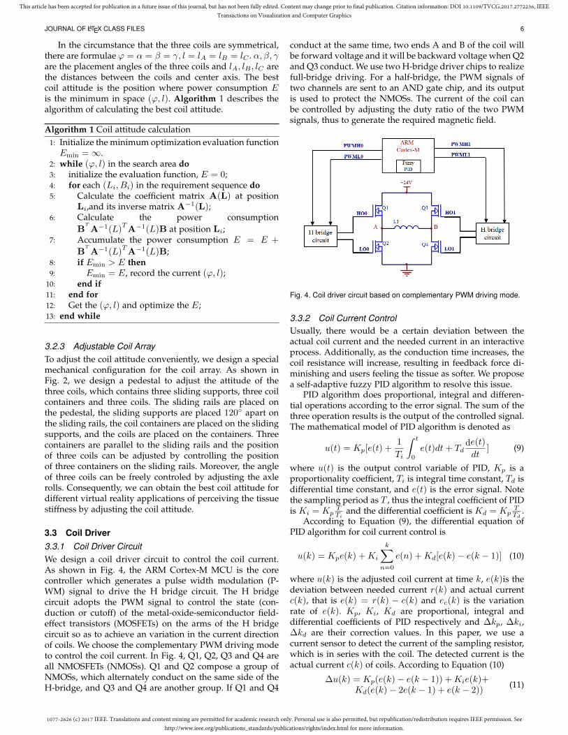
3.3 Coil Driver3.3.1 Coil Driver CircuitWe design a coil driver circuit to control the coil current.As shown in Fig. 4, the ARM Cortex-M MCU is the corecontroller which generates a pulse width modulation (P-WM) signal to drive the H bridge circuit. The H bridgecircuit adopts the PWM signal to control the state (con-duction or cutoff) of the metal-oxide-semiconductor field-effect transistors (MOSFETs) on the arms of the H bridgecircuit so as to achieve an variation in the current directionof coils. We choose the complementary PWM driving modeto control the coil current. In Fig. 4, Q1, Q2, Q3 and Q4 areall NMOSFETs (NMOSs). Q1 and Q2 compose a group ofNMOSs, which alternately conduct on the same side of theH-bridge, and Q3 and Q4 are another group. If Q1 and Q4
conduct at the same time, two ends A and B of the coil willbe forward voltage and it will be backward voltage when Q2and Q3 conduct. We use two H-bridge driver chips to realizefull-bridge driving. For a half-bridge, the PWM signals oftwo channels are sent to an AND gate chip, and its outputis used to protect the NMOSs. The current of the coil canbe controlled by adjusting the duty ratio of the two PWMsignals, thus to generate the required magnetic field.
Fig. 4. Coil driver circuit based on complementary PWM driving mode.
3.3.2 Coil Current ControlUsually, there would be a certain deviation between theactual coil current and the needed current in an interactiveprocess. Additionally, as the conduction time increases, thecoil resistance will increase, resulting in feedback force di-minishing and users feeling the tissue as softer. We proposea self-adaptive fuzzy PID algorithm to resolve this issue.
PID algorithm does proportional, integral and differen-tial operations according to the error signal. The sum of thethree operation results is the output of the controlled signal.The mathematical model of PID algorithm is denoted as
u(t) = Kp[e(t) +1
Ti
∫ t
0
e(t)dt+ Tdde(t)
dt] (9)
where u(t) is the output control variable of PID, Kp is aproportionality coefficient, Ti is integral time constant, Td isdifferential time constant, and e(t) is the error signal. Notethe sampling period as T , thus the integral coefficient of PIDis Ki = Kp
TTi
and the differential coefficient is Kd = KpTTd
.According to Equation (9), the differential equation of
PID algorithm for coil current control is
u(k) = Kpe(k) +Ki
k∑n=0
e(n) +Kd[e(k)− e(k − 1)] (10)
where u(k) is the adjusted coil current at time k, e(k)is thedeviation between needed current r(k) and actual currentc(k), that is e(k) = r(k) − c(k) and ec(k) is the variationrate of e(k). Kp, Ki, Kd are proportional, integral anddifferential coefficients of PID respectively and ∆kp, ∆ki,∆kd are their correction values. In this paper, we use acurrent sensor to detect the current of the sampling resistor,which is in series with the coil. The detected current is theactual current c(k) of coils. According to Equation (10)
∆u(k) = Kp(e(k)− e(k − 1)) +Kie(k)+Kd(e(k)− 2e(k − 1) + e(k − 2))
(11)

1077-2626 (c) 2017 IEEE. Translations and content mining are permitted for academic research only. Personal use is also permitted, but republication/redistribution requires IEEE permission. Seehttp://www.ieee.org/publications_standards/publications/rights/index.html for more information.
This article has been accepted for publication in a future issue of this journal, but has not been fully edited. Content may change prior to final publication. Citation information: DOI 10.1109/TVCG.2017.2772236, IEEETransactions on Visualization and Computer Graphics
JOURNAL OF LATEX CLASS FILES 7
where ∆u(k) is the coil current increment calculated by PIDalgorithm at time k.
The difficulty of the classical PID algorithm lies in theparameter self-tuning in the proportional, integral and dif-ferential link. For general accuracy requirements, the patch-work approach can be used. To improve the performance ofour haptic device and ensure accurate stiffness perception,we adopt the idea of fuzzy reasoning. The on-line self-tuning of Kp, Ki, and Kd are performed according to dif-ferent current deviations e(k) and variation rates ec(k). Thekey to design a fuzzy PID controller is creating a suitablefuzzy rule table. Our fuzzy rules are developed accordingto the current deviation e and deviation variation rate ec ofcoil current. When |e| is bigger, we should take a larger Kp
to speed up the system response, and take a smaller Kd toavoid differential saturation, and limit the role of integrationto avoid overshoot. When |e| and |ec| is medium, Kp shouldbe smaller and Kd and Ki should be moderate. When |e| issmaller, that is the actual current c(k) is close to the neededcurrent r(k), Kp and Ki should be increased and Kd can bebigger if |ec| is small, otherwise, Kd can be smaller.
Supposing that ∆kp, ∆ki, and ∆kd are the correctionvalues of Kp, Ki, and Kd, respectively. Firstly, the deviatione, deviation variation rate ec as well as the outputs ∆kp,∆ki, and ∆kd are fuzzed using a triangular membershipfunction, denoting the fuzzy linguistic variables of e, ec asE, Ec. The fuzzy output is then calculated by solving thefuzzy relational equation using a fuzzy reasoning of takingsmall operation according to our designed fuzzy rules.Then, the precise value is calculated using the weightedaverage method to acquire the actual outputs of ∆kp, ∆ki,and ∆kd after the scale transformation. Finally, we obtainthe PID parametersKp,Ki, andKd, which are used to calcu-late the incremental value of the PWM signal. Consequently,the ARM Cortex-M MCU accomplishes control of the coilcurrent in real time. Algorithm 2 describes the intelligentcontrol algorithm for coil current.
4 EXPERIMENTS
To evaluate the performance of our magnetic levitationhaptic device, we conducted quantitative and qualitativeexperiments. In the quantitative experiment, we firstly com-pared the experimental and simulation data of magneticflux density generated by a single coil as well as three coils.Next, we designed a calibration platform and evaluated theaccuracy of our stereoscopic tracking module. Subsequently,we analyzed the effectiveness of our designed adjustablecoil array. Finally, the performance of the presented self-adaptive fuzzy PID algorithm was verified. In the qual-itative experiment, the designed device was subjectivelycompared with the Phantom Omni device by recruiting par-ticipants to distinguish objects of different stiffness, detecttissue abnormality and complete a questionnaire.
4.1 Quantitative Experiment
4.1.1 Comparison of Experimental and Simulation Data ofMagnetic Flux DensityWe performed two groups of comparative experiments forthe experimental and simulation data of a single coil. One
Algorithm 2 Self-adaptive fuzzy PID for coil current control1: Initialize system configuration, such as the PWM con-
troller, timer, etc.; Initialize the needed current flag flag1,the actual coil current flag flag2, and coil current updateflag flag3 as 0; Initialize PID parameters Kp0, Ki0, Kd0.
2: while 1 do3: if flag1==1 (set by interruption) then4: Digitize the needed current r, flag1=0;5: end if6: if flag2==1 (set by interruption) then7: Obtain the actual coil current c,flag2=0,flag3=1;8: end if9: if flag3==1 then
10: Calculate the error e and its change rate ec;11: Fuzz e, ec and the fuzzy output ∆kp, ∆ki, ∆kd
using a triangular membership function;12: Query fuzzy rule table, calculate the fuzzy output;13: Calculate the precise value of the fuzzy output
using weighted average method, and acquire actual∆kp, ∆ki, ∆kd by scale transformation;
14: Adjust Kp0, Ki0, Kd0 using ∆kp, ∆ki, ∆kd;15: Calculate the output signal pwmout;16: Limit pwmout according to the set threshold;17: end if18: end while
TABLE 1Comparison between the experimental and simulation data of magnetic
flux density for a single coil.
Distance(mm)
Experimental data (mT) Simulation data (mT)0.5 1.0 1.5 2.0 0.5 1.0 1.5 2.0
69 15 28.8 40 53.2 13 26.3 39 52.174 9.4 18 26.6 35.6 8.26 16.6 25 32.779 6.1 11.8 17.5 21.2 5.47 11.1 16 22.184 4.1 7.8 11.9 14.2 3.64 7.56 11 14.489 2.6 5.1 7.7 9.9 2.7 5.3 8.0 10.894 2.0 4.0 5.8 7.1 2.03 4.07 6.0 7.9699 1.5 2.9 4.4 5.3 1.54 3.12 4.6 6.18104 1.1 2.2 3.3 3.9 1.14 2.29 3.5 4.67109 0.9 1.7 2.4 3.1 0.99 1.20 3.0 3.99114 0.7 1.4 1.9 2.5 0.81 1.65 2.5 3.28119 0.5 1.1 1.6 1.9 0.69 1.38 2.1 2.74124 0.4 0.9 1.4 1.7 0.56 1.12 1.67 2.28
is the relationship between the magnetic flux density andthe position when the coil current is steady. The other is therelationship between the magnetic field distribution and thecurrent. The magnetic field of a certain continuous positionof the z axis was measured from (0, 0, 69) to (0, 0, 124) witha step size of 5 mm at 0.5 A, 1 A, 1.5 A and 2 A. Table 1shows the experimental and simulation data for a singlecoil. The magnetic flux density of three-coil is measuredat 1A and 2A in different positions on the coil center axis(from (0, 0, 80) to (0, 0,130) with the step of 5 mm). Table 2shows the experimental and simulation data of magneticflux density on the coil center axis, and the three coils areplaced according to the configuration of section 3.2.3.
As shown in Fig. 5, the horizontal coordinate representsthe position of the central axis, and the vertical coordinaterepresents the magnetic flux density in space. It is apparentthat the simulation data and the experimental data are sig-
1077-2626 (c) 2017 IEEE. Translations and content mining are permitted for academic research only. Personal use is also permitted, but republication/redistribution requires IEEE permission. Seehttp://www.ieee.org/publications_standards/publications/rights/index.html for more information.
This article has been accepted for publication in a future issue of this journal, but has not been fully edited. Content may change prior to final publication. Citation information: DOI 10.1109/TVCG.2017.2772236, IEEETransactions on Visualization and Computer Graphics
JOURNAL OF LATEX CLASS FILES 8
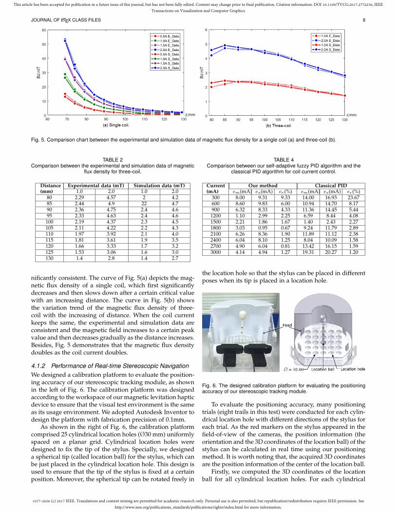
Fig. 5. Comparison chart between the experimental and simulation data of magnetic flux density for a single coil (a) and three-coil (b).
TABLE 2Comparison between the experimental and simulation data of magnetic
flux density for three-coil.
Distance(mm)
Experimental data (mT) Simulation data (mT)1.0 2.0 1.0 2.0
80 2.29 4.57 2 4.285 2.44 4.9 22 4.790 2.36 4.75 2.4 4.695 2.33 4.63 2.4 4.6100 2.19 4.37 2.3 4.5105 2.11 4.22 2.2 4.3110 1.97 3.92 2.1 4.0115 1.81 3.61 1.9 3.5120 1.66 3.33 1.7 3.2125 1.53 3.06 1.6 3.0130 1.4 2.8 1.4 2.7
nificantly consistent. The curve of Fig. 5(a) depicts the mag-netic flux density of a single coil, which first significantlydecreases and then slows down after a certain critical valuewith an increasing distance. The curve in Fig. 5(b) showsthe variation trend of the magnetic flux density of three-coil with the increasing of distance. When the coil currentkeeps the same, the experimental and simulation data areconsistent and the magnetic field increases to a certain peakvalue and then decreases gradually as the distance increases.Besides, Fig. 5 demonstrates that the magnetic flux densitydoubles as the coil current doubles.
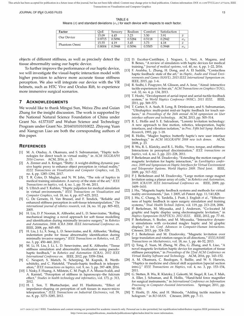
4.1.2 Performance of Real-time Stereoscopic NavigationWe designed a calibration platform to evaluate the position-ing accuracy of our stereoscopic tracking module, as shownin the left of Fig. 6. The calibration platform was designedaccording to the workspace of our magnetic levitation hapticdevice to ensure that the visual test environment is the sameas its usage environment. We adopted Autodesk Inventor todesign the platform with fabrication precision of 0.1mm.
As shown in the right of Fig. 6, the calibration platformcomprised 25 cylindrical location holes (Ø30 mm) uniformlyspaced on a planar grid. Cylindrical location holes weredesigned to fix the tip of the stylus. Specially, we designeda spherical tip (called location ball) for the stylus, which canbe just placed in the cylindrical location hole. This design isused to ensure that the tip of the stylus is fixed at a certainposition. Moreover, the spherical tip can be rotated freely in
TABLE 4Comparison between our self-adaptive fuzzy PID algorithm and the
classical PID algorithm for coil current control.
Current(mA)
Our method Classical PIDem(mA) es(mA) er(%) em(mA) es(mA) er(%)
300 8.00 9.31 9.33 14.00 16.93 23.67600 8.60 9.83 6.00 10.94 14.70 8.17900 6.32 8.33 4.33 11.36 14.45 5.441200 1.10 2.99 2.25 6.59 8.44 4.081500 2.21 1.86 1.67 1.40 2.43 2.271800 3.03 0.95 0.67 9.24 11.79 2.892100 6.26 8.36 1.90 11.89 11.12 2.382400 6.04 8.10 1.25 8.04 10.09 1.582700 4.90 6.04 0.81 13.42 16.15 1.593000 4.14 4.94 1.27 19.31 20.27 1.20
the location hole so that the stylus can be placed in differentposes when its tip is placed in a location hole.
Fig. 6. The designed calibration platform for evaluating the positioningaccuracy of our stereoscopic tracking module.
To evaluate the positioning accuracy, many positioningtrials (eight trails in this test) were conducted for each cylin-drical location hole with different directions of the stylus foreach trial. As the red markers on the stylus appeared in thefield-of-view of the cameras, the position information (theorientation and the 3D coordinates of the location ball) of thestylus can be calculated in real time using our positioningmethod. It is worth noting that, the acquired 3D coordinatesare the position information of the center of the location ball.
Firstly, we computed the 3D coordinates of the locationball for all cylindrical location holes. For each cylindrical

1077-2626 (c) 2017 IEEE. Translations and content mining are permitted for academic research only. Personal use is also permitted, but republication/redistribution requires IEEE permission. Seehttp://www.ieee.org/publications_standards/publications/rights/index.html for more information.
This article has been accepted for publication in a future issue of this journal, but has not been fully edited. Content may change prior to final publication. Citation information: DOI 10.1109/TVCG.2017.2772236, IEEETransactions on Visualization and Computer Graphics
JOURNAL OF LATEX CLASS FILES 9
TABLE 3Performance of our stereoscopic tracking module. Positioning errors (σ) of 3D coordinates for 25 location holes.
Hole σx (mm) σy (mm) σz (mm) σD (mm) Hole σx (mm) σy (mm) σz (mm) σD (mm)1 0.56 0.37 0.31 0.31 14 0.57 0.65 0.37 0.412 0.40 0.20 0.39 0.25 15 0.50 0.57 0.33 0.323 0.34 0.39 0.36 0.23 16 0.64 0.16 0.41 0.384 0.40 0.46 0.54 0.35 17 0.70 0.37 0.42 0.395 0.50 0.55 0.45 0.26 18 0.35 0.39 0.53 0.236 0.40 0.28 0.56 0.29 19 0.40 0.29 0.42 0.217 0.40 0.12 0.34 0.18 20 0.38 0.48 0.41 0.178 0.58 0.33 0.41 0.35 21 0.51 0.30 0.44 0.249 0.66 0.58 0.50 0.36 22 0.46 0.32 0.41 0.2110 0.50 0.57 0.51 0.43 23 0.47 0.47 0.32 0.3211 0.50 0.23 0.39 0.20 24 0.51 0.27 0.55 0.2412 0.53 0.43 0.36 0.30 25 0.20 0.27 0.14 0.1613 0.54 0.44 0.31 0.22 Mean 0.48 0.38 0.41 0.28
location hole, we analyzed the coordinate of each dimension(x, y, z) for multiple positioning trails by computing theirstandard deviation (σ). Besides, we computed the standarddeviation of 3D position (σD) by calculating the distancebetween two positioning trails. Table 3 shows the analysisresults for 25 cylindrical location holes. The mean value ofstandard deviation for 25 cylindrical location holes is shownin the ”Mean“ row of Table 3. The mean value of standarddeviation for 3D position is 0.28 mm, which demonstrateshigh accuracy of our stereoscopic tracking module.
When we detect red markers on the whole image (theresolution is 1280 × 720) using a recursion method andparallel processing, the positioning speed can reach about40Hz. In this paper, we divide the whole image into manyregions and detect red pixels of each region using the par-allel processing and multi-threading processing technology.Consequently, our stereoscopic tracking module can reach200Hz while ensuring 3D positioning accuracy of 0.28mm.
4.1.3 Results of Coil Attitude CalculationTo assess the effectiveness of our adjustable coil array, wedesigned two different interaction application requirements.The first one is the interaction application of a stylus and anelastic circular plane. The other one is the interaction ap-plication of a stylus and an elastic hemisphere. As shown inFig. 7, the left of Fig. 7(a) shows the interactive requirementsof the elastic circular plane, and the left of Fig. 7(b) showsthe interactive requirements of the elastic hemisphere. Usingthe constraints of (ϕ ∈ [0◦, 90◦], l > 2√
3R2), we calculated
out the best coil attitudes for both interactive requirementsadopting the algorithm presented in section 3.2.2. The resultof the the elastic circular plane is (ϕ0, l0) = (90◦, 43.3), andthe result of the elastic hemisphere is (ϕ0, l0) = (80.4◦, 42).We can see that the best coil angle for the elastic circularplane is vertical, which is similar to Berkelman [24], [25].The best coil angle for the elastic hemisphere towards theinteraction area, which is completely consistent with oursimulation results described in 3.2.1.
We compared the calculated best attitude for the elasticcircular plane (the left of Fig. 7(a)) with two other coilattitudes which are similar to that of Berkelman [24], [25]and two other similar to that of Hu [22], [23]. The rightof Fig. 7(a) shows their comparison results of power con-sumption. Its horizontal axis denotes the whole interactiveprocess and the vertical axis is the power consumption of
one interactive operation. Thus the area between the lineand the horizontal axis is the total power consumption. Thered line denotes our coil attitude (ϕ0, l0) = (90◦, 43.3), andthe blue line and green line denote two coil attitudes similarto Berkelman [24], [25], which are (ϕ0, l0) = (90◦, 47.3) and(ϕ0, l0) = (90◦, 50.3), respectively. Apparently, the red lineis lower than the blue line and green line. Moreover, theyellow line and cyan line denote two coil attitudes similarto Hu’s method [22], [23]. The power consumption of thesetwo coil attitudes is also higher than ours.
Additionally, we compared the calculated best attitudefor the elastic hemisphere with the coil attitude employedby Berkelman [24], [25] and three other coil attitudes similarto Hu’s method [22], [23]. The right of Fig. 7(b) showsthe comparison results of power consumption. The red linedenotes our coil attitude (ϕ0, l0) = (80.4◦, 42), and the blueline denotes Berkelman’s coil attitude (ϕ, l) = (90◦, 42). Thered line is lower than other four lines, which also demon-strates that the coil attitude calculated by our algorithm caneffectively reduce coil power consumption.
4.1.4 Performance of Self-adaptive Fuzzy PID AlgorithmTo evaluate the performance of the proposed self-adaptivefuzzy PID algorithm, we firstly compared our method withthe classical PID algorithm. In the experiment, we adjusteddifferent currents using these two methods (the currentrange is 300–3000mA, and the step is 300mA). For each cur-rent, we analyzed the mean error (em), standard deviation(es) and the maximum relative error (er) of 1000 adjustedsamples. The comparison results are shown in Table 4. Itcan be observed that the mean error, standard deviation andmaximum relative error of our algorithm are all smaller thanthe classical PID algorithm. Specially, the mean value of themaximum relative error of our algorithm is 2.95%, reducingby 2.38% compared with the classical PID algorithm whichachieves 5.33%. The parameters of the classical PID algorith-m are Kp = 0.2,Ki = 0.5, and Kd = 0.1, which are used asinitial parameters of our algorithm.
The stability and smoothness of the magnetic field is sig-nificantly important for providing highly immersive hapticperception. We then evaluated the performance of our self-adaptive fuzzy PID algorithm for controlling continuouslychanging current and compared the actual magnitude of themagnetic flux density with the experimental magnitude ofthe magnetic flux density B. The blue line of Fig. 8(a) depicts

1077-2626 (c) 2017 IEEE. Translations and content mining are permitted for academic research only. Personal use is also permitted, but republication/redistribution requires IEEE permission. Seehttp://www.ieee.org/publications_standards/publications/rights/index.html for more information.
This article has been accepted for publication in a future issue of this journal, but has not been fully edited. Content may change prior to final publication. Citation information: DOI 10.1109/TVCG.2017.2772236, IEEETransactions on Visualization and Computer Graphics
JOURNAL OF LATEX CLASS FILES 10
Fig. 7. Performance of our coil attitude calculation algorithm. For figure (a) and (b), the right part denotes the corresponding interactive requirementand the right denotes comparison results of different coil attitudes.
the actual magnitude of the magnetic flux density. The bluesolid line, red solid line and green solid line of Fig. 8(b)denote the calculated current of three coils adopting themethod of [26]. The blue dotted line, red dotted line andgreen dotted line of Fig. 8(b) denote their correspondingcontrolled results using the proposed fuzzy PID algorithm,respectively. The horizontal axis of Fig. 8 denotes the wholeinteractive process and the value (current and magnetic ofB) of vertical axis changes with time during the interactiveprocess. We can see that the controlled current is consistentwith the calculated current. The red line of Fig. 8(a) depictsthe magnitude of B generated by the controlled current, andit is close to the actual magnitude of B. Therefore, our hapticdevice can provide highly immersive haptic perception.
4.2 Qualitative ExperimentTwo qualitative experiments were conducted to evaluate theperformance of our magnetic levitation haptic device onaugmenting the tissue stiffness perception. Experiment 1 isused to evaluate the reliability of our haptic device to dis-tinguish objects of different stiffness. Experiment 2 is usedto evaluate the accuracy of detecting tissue abnormality.
4.2.1 ParticipantsWe recruited 22 participants (9 females and 13 males; with amean age of 28 years old) among students and teachers. Toensure the objectivity of the experiments, nineteen partici-pants had no previous experience with our magnetic hapticdevice. All of the participants did not know the goal anddesign of the experiments.
4.2.2 ApparatusThe test hardware is our magnetic levitation haptic proto-type device described in section 3. Three coils of the device
are placed 120◦ apart. The angle between each coil and thehorizontal plane is 60◦, and the distance between two coils is40 mm. Phantom Omni is used to compare with our devicefor the tissue stiffness perception. The tasks of calculatingour simulation model, solving the coil current and trackingthe magnetic stylus are performed on a PC (Intel Xeon CPUE3-1230 V2 @ 3.30 GHz, 8.00 GB of memory).
4.2.3 DesignIn experiment 1, we designed six levels of stiffness for thekidney model from small to large: A B, C, D, E, and F. Theappearances of all six objects are identical. Objects A, C,and E are first used to familiarize the participants with ourhaptic device and to train them to experience the process oftissue stiffness perception. Next, we disrupt the orders of A,C, E and B, D, F respectively, and the participants are askedto sort the objects according to their perception experienceby using the designed haptic device and the Phantom Omni.
As shown in Fig. 9, we embedded a lump in a kidneyas the abnormal tissue, and the other kidney is the normaltissue in experiment 2.
We model the real-time deformation of kidney usingVega, which is a nonlinear FEM deformable object simulatorexploited by Sin et al. [44]. The parameters of our model areas follows: the number of vertices is 16680; the number ofelements is 8466; the simulation frame rate is 60Hz.
4.2.4 ProcedureParticipants individually entered the laboratory, and theyhad no communication with each other. Two experimentsare divided into two stages. After all participants completedthe first experiment, we counted and analyzed the exper-imental results. If more than 80% of the participants can

1077-2626 (c) 2017 IEEE. Translations and content mining are permitted for academic research only. Personal use is also permitted, but republication/redistribution requires IEEE permission. Seehttp://www.ieee.org/publications_standards/publications/rights/index.html for more information.
This article has been accepted for publication in a future issue of this journal, but has not been fully edited. Content may change prior to final publication. Citation information: DOI 10.1109/TVCG.2017.2772236, IEEETransactions on Visualization and Computer Graphics
JOURNAL OF LATEX CLASS FILES 11
Fig. 8. Performance of our self-adaptive fuzzy PID algorithm for controlling continuously changing current.
accurately distinguish the tissue of different stiffness, wecontinued to conduct the second experiment.
The participant read and signed an informed consentsheet after entering the laboratory. It is widely known thatthere may be sickness phenomenon in the experience of ARand VR. We told each participant he or she could inter-rupt the experiment at any time if encountering problems.Participants attempted to use our device according to ourguidelines. After the preparatory work was completed, theparticipant conducted the training task. During the trainingtask, objects A, C, and E were sorted from small to largeaccording to the stiffness. The goal of the training task is tolet the participant experience objects of different stiffness.
We conducted the first test of experiment 1 after thetraining task was completed. The participant was asked tosort the objects A, C, and E, whose order was shuffled.We counted the results and then conducted the second testof experiment 1. The participant perceived objects B, D,and F and sorted them, and the results were counted. Theparticipant had no interaction with objects B, D, and F usingour haptic device before the test, ensuring the credibility ofour experiment. The participant would then rest and wait ina separate waiting area after finishing experiment 1.
Fig. 9. Kidney model. The left is the normal tissue and the right is theabnormal tissue embedded with a lump.
In experiment 2, each participant was told to detectwhether the kidney model contained lesions in the virtualenvironment. All participants were aware that the stiffnessof diseased tissue is higher than that of surrounding normaltissue [5]. We told the participants that each kidney maybe in one of three conditions: (1) Neither contains tissueabnormality; (2) Only one contains tissue abnormality; (3)Both contain tissue abnormality.
4.2.5 Measurement of QoE: QuestionnaireAfter finishing experiment 2, each participant was asked tofill in a questionnaire, which is designed to evaluate the us-
TABLE 5QoE Questionnaire. Each question is rated on a 5-point scale from 1
(Not at all) to 5 (Totally).
Factor Question
Sensory How much did the haptic device contribute to aug-menting the stiffness perception of tissue?Whether the interaction way is consistent with yourhabits of the real world?
Realism How much did the perceived experiences seem con-sistent with your real-world experiences?
Comfort How comfortable was the haptic device?Satisfaction How much did you prefer to use the device?
er’s perceived quality of experience (QoE) for tissue stiffnessperception. QoE is related to the subjective user experiencewith a service or an application [45]. As shown in Table 5,our questionnaire is based on four factors [46], [47]: Sensory,Realism, Comfort and Satisfaction. “Sensory” characterizeshow much the haptic device contributed to augmenting thestiffness perception of tissue and whether the interactionway is consistent with user’s habits of the real world.“Realism” describes how much the virtual environment isrealistic. “Comfort” measures how comfortable the hapticdevice is to use. “Satisfaction” determines whether the userprefers to use the device. Each factor was evaluated byquestions rated on a 5-point scale. The mean value wascalculated for each factor, and QoE was computed as thesum of these 4 factors.
4.2.6 ResultsIn Experiment 1, the participants distinguished the kidneymodels of different stiffness. The statistical results of test 1and test 2 using our device and Phantom Omni are shown inFig. 10. 21 participants (95%) successfully distinguished theobjects of different stiffness in test 1. In test 2, two partic-ipants wrongly sorted the two models of smaller stiffness(objects B and D) using the designed haptic device andtwo participants appeared the same mistake using PhantomOmni. It is worth noting that one participant made mistakesin two tests, and it may result from his poor ability of hapticperception. The accuracy rate of test 2 is 91%, showingthat our haptic device has a ability to distinguish objects ofdifferent stiffness. In Experiment 2, all participants correctlydetected the normal tissue and the abnormal tissue by usingthe two haptic devices.

1077-2626 (c) 2017 IEEE. Translations and content mining are permitted for academic research only. Personal use is also permitted, but republication/redistribution requires IEEE permission. Seehttp://www.ieee.org/publications_standards/publications/rights/index.html for more information.
This article has been accepted for publication in a future issue of this journal, but has not been fully edited. Content may change prior to final publication. Citation information: DOI 10.1109/TVCG.2017.2772236, IEEETransactions on Visualization and Computer Graphics
JOURNAL OF LATEX CLASS FILES 12
Fig. 10. Number of participants to accurately distinguish correspondingobjects using the designed device and Phantom Omni.
In addition, a score for the four factors (Sensory, Realism,Comfort and Satisfaction) were obtained using a question-naire. The QoE is the sum of four factors. The statisticalresults are shown in Fig. 11 and Table 6. In Table 6, wecomputed the average x and standard deviation σx of eachfactor. In addition, we conducted a nonparametric test toanalyze the statistical results. The QoE of our haptic deviceis not significantly different from that of Phantom Omni(QoEOur = 15.09 ≈ QoEPhantom = 15.55, Mann-WhitneyU test p = 0.1573 > 0.05, effect size is ES = 0.52 andstatistical power is power = 0.50). Therefore, our devicesignificantly enhances the quality of experience. The “Sen-sory” score of our device is higher than that of PhantomOmni. Taking into account that the accuracy rate of distin-guishing objects of different stiffness is identical using thetwo devices, the higher score of “Sensory” is possible due tothe way of our device is closer to the natural manner.
5 DISCUSSION
The quantitative results show that the simulation data ofthe magnetic flux density used to generate force feedbackis consistent with the experimental data. The presentedself-adaptive fuzzy PID algorithm can control coil currentaccurately, which ensures precise haptic perception of thedesigned haptic device. The positioning performance ofour stereoscopic tracking module was evaluated using thedesigned calibration platform. Although the location ballused in the experiment is bigger than the actual tip of ourmagnetic stylus, the position tracked by our stereoscopictracking module is the actual position of the center ofthe location ball, which benefits from the design that redmarkers are embedded in the magnetic stylus. Moreover,our design can ensure that the tracking module tracks thesame position in different trials for each location hole.
For the coil configuration of our haptic device, we havereasonably explained the design of the coil array comparedto the existing methods [23], [26]. We describe interactiverequirements using probability clouds and further presentan algorithm to calculate the best coil attitude. The exper-imental results demonstrate its advantage of low powerconsumption, and it is easy to expand our haptic device toother applications such as entertainment industry. However,we just focus on two parameters of the coil configuration,
Fig. 11. Quality of experience. The QoE of our haptic device is notsignificantly different from that of Phantom Omni.
that is the angle of each coil and the distance between coils,more coil parameters such as the number and the shape ofcoils should be concerned in future work.
The preliminary qualitative results demonstrate that ourdevice can help users to distinguish objects of different stiff-ness and correctly detect tissue abnormality in the virtualenvironment. Therefore, the designed device has the poten-tial for augmenting tissue stiffness perception in surgicalsimulation. The QoE of our haptic device is lower than thatof Phantom Omni. However, the “Sensory” score of ourdevice is higher. Our device does not require mechanicaltransmission and the magnetic stylus is flexible, thus theuser can interact with virtual objects in a natural manner.Therefore, the higher “Sensory” score benefits from thequestion “Whether the interaction way is consistent withyour habits of the real world”.
In this paper, tissue deformation model was built usingthe Vega software [44], which achieves real-time deforma-tion simulation by reducing the dimension of the model.However, the process of dimension reduction would affectthe accuracy of the force feedback, which is one reasonwhy the score of “Realism” factor is slightly lower in thequestionnaire. In addition, we simulate tissue of differentstiffness by setting different stiffness matrix for the objectsand we obtained a tissue abnormality by embedding a lumpinto a normal tissue, which also affects the realistic of ourmodel. To achieve realistic perception of tissue stiffness, ahigh precision simulation model needs to be studied forreal-time haptic interaction.
6 CONCLUSION AND FUTURE WORK
We design a novel magnetic levitation haptic device foraugmenting virtual tissue stiffness perception in this paper.Users can sense tissue in the virtual environment using thedesigned magnetic stylus in a natural manner. We presentto calculate the best coil attitude and design an adjustablecoil array, which provides a reasonable explanation of coilconfiguration compared with the existing methods. Thecalculated best coil attitude is beneficial for taking full ad-vantage of the magnetic field. The quantitative experimentsdemonstrate advantages of high accuracy and low powerconsumption of the designed haptic device. In the qualita-tive experiments, the participants can accurately distinguish
1077-2626 (c) 2017 IEEE. Translations and content mining are permitted for academic research only. Personal use is also permitted, but republication/redistribution requires IEEE permission. Seehttp://www.ieee.org/publications_standards/publications/rights/index.html for more information.
This article has been accepted for publication in a future issue of this journal, but has not been fully edited. Content may change prior to final publication. Citation information: DOI 10.1109/TVCG.2017.2772236, IEEETransactions on Visualization and Computer Graphics
JOURNAL OF LATEX CLASS FILES 13
TABLE 6Means (x) and standard deviations (σx) for each device with respects to each factor.
Factor QoE Sensory Realism Comfort Satisfaction
Our Device 15.09 4.45 3.23 3.50 3.91 x0.9715 0.5096 0.5284 0.5118 0.2942 σx
Phantom Omni 15.55 4.19 3.45 3.73 4.18 x0.8004 0.3948 0.5096 0.5505 0.3948 σx
objects of different stiffness, as well as precisely detect thetissue abnormality using our haptic device.
To further improve the performance of our haptic device,we will investigate the visual-haptic interaction model withhigher precision to achieve more accurate tissue stiffnessperception. We also will integrate our device with the VRhelmets, such as HTC Vive and Oculus Rift, to experiencemore immersive surgical scenarios.
7 ACKNOWLEDGMENTS
We would like to thank Mingui Sun, Weixu Zhu and GuianZhang for the insight discussion. The work is supported bythe National Natural Science Foundation of China underGrant No. 61373107 and Wuhan Science and TechnologyProgram under Grant No. 2016010101010022. Zhiyong Yuanand Xiangyun Liao are both the corresponding authors ofthis paper.
REFERENCES
[1] M. A. Otaduy, A. Okamura, and S. Subramanian, “Haptic tech-nologies for direct touch in virtual reality,” in ACM SIGGRAPH2016 Courses. ACM, 2016, p. 13.
[2] A. Zenner and A. Kruger, “Shifty: A weight-shifting dynamic pas-sive haptic proxy to enhance object perception in virtual reality,”IEEE Transactions on Visualization and Computer Graphics, vol. 23,no. 4, pp. 1285–1294, 2017.
[3] T. R. Coles, D. Meglan, and N. W. John, “The role of haptics inmedical training simulators: A survey of the state of the art,” IEEETransactions on haptics, vol. 4, no. 1, pp. 51–66, 2011.
[4] S. Ullrich and T. Kuhlen, “Haptic palpation for medical simulationin virtual environments,” IEEE Transactions on Visualization andComputer Graphics, vol. 18, no. 4, pp. 617–625, 2012.
[5] G. De Gersem, H. Van Brussel, and F. Tendick, “Reliable andenhanced stiffness perception in soft-tissue telemanipulation,” Theinternational journal of robotics research, vol. 24, no. 10, pp. 805–822,2005.
[6] H. Liu, D. P. Noonan, K. Althoefer, and L. D. Seneviratne, “Rollingmechanical imaging: a novel approach for soft tissue modellingand identification during minimally invasive surgery,” in Roboticsand Automation, 2008. ICRA 2008. IEEE International Conference on.IEEE, 2008, pp. 845–850.
[7] H. Liu, J. Li, X. Song, L. D. Seneviratne, and K. Althoefer, “Rollingindentation probe for tissue abnormality identification duringminimally invasive surgery,” IEEE Transactions on Robotics, vol. 27,no. 3, pp. 450–460, 2011.
[8] M. Li, H. Liu, J. Li, L. D. Seneviratne, and K. Althoefer, “Tissuestiffness simulation and abnormality localization using pseudo-haptic feedback,” in Robotics and Automation (ICRA), 2012 IEEEInternational Conference on. IEEE, 2012, pp. 5359–5364.
[9] C. Neupert, S. Matich, N. Scherping, M. Kupnik, R. Werth-schutzky, and C. Hatzfeld, “Pseudo-haptic feedback in teleoper-ation,” IEEE transactions on haptics, vol. 9, no. 3, pp. 397–408, 2016.
[10] I. Nisky, F. Huang, A. Milstein, C. M. Pugh, F. A. Mussa-Ivaldi, andA. Karniel, “Perception of stiffness in laparoscopy–the fulcrumeffect,” Studies in health technology and informatics, vol. 173, p. 313,2012.
[11] H. I. Son, T. Bhattacharjee, and H. Hashimoto, “Effect ofimpedance-shaping on perception of soft tissues in macro-microteleoperation,” IEEE Transactions on Industrial Electronics, vol. 59,no. 8, pp. 3273–3285, 2012.
[12] D. Escobar-Castillejos, J. Noguez, L. Neri, A. Magana, andB. Benes, “A review of simulators with haptic devices for medicaltraining,” Journal of medical systems, vol. 40, no. 4, pp. 1–22, 2016.
[13] F. Arafsha, L. Zhang, H. Dong, and A. El Saddik, “Contactlesshaptic feedback: state of the art,” in Haptic, Audio and Visual Envi-ronments and Games (HAVE), 2015 IEEE International Symposium on.IEEE, 2015, pp. 1–6.
[14] R. Sodhi, I. Poupyrev, M. Glisson, and A. Israr, “Aireal: interactivetactile experiences in free air,” ACM Transactions on Graphics (TOG),vol. 32, no. 4, p. 134, 2013.
[15] T. Hoshi, “Development of aerial-input and aerial-tactile-feedbacksystem,” in World Haptics Conference (WHC), 2011 IEEE. IEEE,2011, pp. 569–573.
[16] T. Carter, S. A. Seah, B. Long, B. Drinkwater, and S. Subramanian,“Ultrahaptics: multi-point mid-air haptic feedback for touch sur-faces,” in Proceedings of the 26th annual ACM symposium on Userinterface software and technology. ACM, 2013, pp. 505–514.
[17] R. L. Hollis and S. E. Salcudean, “Lorentz levitation technology:A new approach to fine motion, robotics, teleoperation, hapticinterfaces, and vibration isolation,” in Proc. Fifth Intl Symp. RoboticsResearch, 1993, pp. 1–18.
[18] R. Hollis, “Maglev haptics: butterfly haptic’s new user interfacetechnology,” in ACM SIGGRAPH 2008 new tech demos. ACM,2008, p. 23.
[19] B. Wu, R. L. Klatzky, and R. L. Hollis, “Force, torque, and stiffness:Interactions in perceptual discrimination,” IEEE transactions onhaptics, vol. 4, no. 3, pp. 221–228, 2011.
[20] P. Berkelman and M. Dzadovsky, “Extending the motion ranges ofmagnetic levitation for haptic interaction,” in EuroHaptics confer-ence, 2009 and Symposium on Haptic Interfaces for Virtual Environmentand Teleoperator Systems. World Haptics 2009. Third Joint. IEEE,2009, pp. 517–522.
[21] P. J. Berkelman and M. Dzadovsky, “Large motion range magnetlevitation using a planar array of coils,” in Robotics and Automation,2009. ICRA’09. IEEE International Conference on. IEEE, 2009, pp.1609–1610.
[22] J. Hu, “Magnetic haptic feedback systems and methods for virtualreality environments,” Jun. 1 2005, uS Patent App. 11/141,828.
[23] J. Hu, C. Chang, N. Tardella, J. Pratt, J. English et al., “Effective-ness of haptic feedback in open surgery simulation and trainingsystems,” Stud. Health Technol. Inform, vol. 119, pp. 213–218, 2006.
[24] P. Berkelman, M. Miyasaka, and J. Anderson, “Co-located 3dgraphic and haptic display using electromagnetic levitation,” inHaptics Symposium (HAPTICS), 2012 IEEE. IEEE, 2012, pp. 77–81.
[25] P. Berkelman, S. Bozlee, and M. Miyasaka, “Interactive dynam-ic simulations with co-located maglev haptic and 3d graphicdisplay,” in Int. Conf. Advances in Computer-Human Interactions.Citeseer, 2013, pp. 324–329.
[26] P. J. Berkelman and M. Dzadovsky, “Magnetic levitation overlarge translation and rotation ranges in all directions,” IEEE/ASMETransactions on Mechatronics, vol. 18, no. 1, pp. 44–52, 2013.
[27] Q. Tong, Z. Yuan, M. Zheng, W. Zhu, G. Zhang, and X. Liao, “Anovel magnetic levitation haptic device for augmentation of tissuestiffness perception,” in Proceedings of the 22nd ACM Conference onVirtual Reality Software and Technology. ACM, 2016, pp. 143–152.
[28] A. M. Okamura, C. Basdogan, S. Baillie, and W. S. Harwin,“Haptics in medicine and clinical skill acquisition [special sectionintro.],” IEEE Transactions on Haptics, vol. 4, no. 3, pp. 153–154,2011.
[29] G. Stetten, B. Wu, R. Klatzky, J. Galeotti, M. Siegel, R. Lee, F. Mah,A. Eller, J. Schuman, and R. Hollis, “Hand-held force magnifierfor surgical instruments,” in International Conference on InformationProcessing in Computer-Assisted Interventions. Springer, 2011, pp.90–100.
[30] T. Hoshi, D. Abe, and H. Shinoda, “Adding tactile reaction tohologram.” in RO-MAN. Citeseer, 2009, pp. 7–11.

1077-2626 (c) 2017 IEEE. Translations and content mining are permitted for academic research only. Personal use is also permitted, but republication/redistribution requires IEEE permission. Seehttp://www.ieee.org/publications_standards/publications/rights/index.html for more information.
This article has been accepted for publication in a future issue of this journal, but has not been fully edited. Content may change prior to final publication. Citation information: DOI 10.1109/TVCG.2017.2772236, IEEETransactions on Visualization and Computer Graphics
JOURNAL OF LATEX CLASS FILES 14
[31] B. Long, S. A. Seah, T. Carter, and S. Subramanian, “Renderingvolumetric haptic shapes in mid-air using ultrasound,” ACMTransactions on Graphics (TOG), vol. 33, no. 6, p. 181, 2014.
[32] S. B. Kesner and R. D. Howe, “Discriminating tissue stiffness witha haptic catheter: Feeling the inside of the beating heart,” in WorldHaptics Conference (WHC), 2011 IEEE. IEEE, 2011, pp. 13–18.
[33] Z. F. Quek, S. B. Schorr, I. Nisky, A. M. Okamura, and W. R.Provancher, “Augmentation of stiffness perception with a 1-degree-of-freedom skin stretch device,” IEEE Transactions onHuman-Machine Systems, vol. 44, no. 6, pp. 731–742, 2014.
[34] M. Li, A. Faragasso, J. Konstantinova, V. Aminzadeh, L. D. Senevi-ratne, P. Dasgupta, and K. Althoefer, “A novel tumor localizationmethod using haptic palpation based on soft tissue probing data,”in Robotics and Automation (ICRA), 2014 IEEE International Confer-ence on. IEEE, 2014, pp. 4188–4193.
[35] R. L. Hollis, S. E. Salcudean, and A. P. Allan, “A six-degree-of-freedom magnetically levitated variable compliance fine-motionwrist: design, modeling, and control,” IEEE Transactions on Roboticsand Automation, vol. 7, no. 3, pp. 320–332, 1991.
[36] P. J. Berkelman and R. L. Hollis, “Lorentz magnetic levitation forhaptic interaction: Device design, performance, and integrationwith physical simulations,” The International Journal of RoboticsResearch, vol. 19, no. 7, pp. 644–667, 2000.
[37] R. L. Hollis, “Butterfly haptics: A high-tech startup [en-trepreneur],” IEEE Robotics & Automation Magazine, vol. 17, no. 4,pp. 14–17, 2010.
[38] R. L. Hollis et al., “Magnetic levitation haptic interface system,”Jul. 30 2013, uS Patent 8,497,767.
[39] P. Berkelman and R. L. Hollis, “Dynamic performance of a mag-netic levitation haptic device,” in Intelligent Systems & AdvancedManufacturing. International Society for Optics and Photonics,1997, pp. 140–149.
[40] P. Berkelman, “A novel coil configuration to extend the motionrange of lorentz force magnetic levitation devices for haptic inter-action,” in Intelligent Robots and Systems, 2007. IROS 2007. IEEE/RSJInternational Conference on. IEEE, 2007, pp. 2107–2112.
[41] P. Berkelman and M. Dzadovsky, “Magnet levitation and trajectoryfollowing motion control using a planar array of cylindrical coils,”in ASME 2008 Dynamic Systems and Control Conference. AmericanSociety of Mechanical Engineers, 2008, pp. 923–930.
[42] Z. Zhang, “A flexible new technique for camera calibration,” IEEETransactions on pattern analysis and machine intelligence, vol. 22,no. 11, pp. 1330–1334, 2000.
[43] M. Pedersoli, J. Gonzalez, A. D. Bagdanov, and J. J. Villanueva,“Recursive coarse-to-fine localization for fast object detection,” inEuropean Conference on Computer Vision. Springer, 2010, pp. 280–293.
[44] F. S. Sin, D. Schroeder, and J. Barbic, “Vega: Non-linear femdeformable object simulator,” in Computer Graphics Forum, vol. 32,no. 1. Wiley Online Library, 2013, pp. 36–48.
[45] K. Kilkki, “Quality of experience in communications ecosystem.”J. UCS, vol. 14, no. 5, pp. 615–624, 2008.
[46] F. Danieau, J. Fleureau, A. Cabec, P. Kerbiriou, P. Guillotel, N. Mol-let, M. Christie, and A. Lecuyer, “Framework for enhancing videoviewing experience with haptic effects of motion,” in 2012 IEEEHaptics Symposium (HAPTICS). IEEE, 2012, pp. 541–546.
[47] F. Danieau, J. Fleureau, P. Guillotel, N. Mollet, A. Lecuyer, andM. Christie, “Hapseat: producing motion sensation with multipleforce-feedback devices embedded in a seat,” in Proceedings of the18th ACM symposium on Virtual reality software and technology.ACM, 2012, pp. 69–76.
Qianqian Tong is a PhD student in Schoolof Computer at Wuhan University. Her re-search interests include human-computer in-teraction, computer vision, machine learingand medical imaging. Contact her at [email protected].
Zhiyong Yuan is a professor in School of Com-puter at Wuhan University. His research interestsinclude virtual reality, human-computer interac-tion, machine learning, embedded system, virtu-al surgery and medical imaging. Contact him [email protected].
Xiangyun Liao is an assistant professor inthe Shenzhen Institute of Advanced Technolo-gy, Chinese Academy of Sciences. His researchinterests include virtual reality, physics basedmodeling and medical imaging. Contact him [email protected].
Mianlun Zheng is a master student in Schoolof Computer at Wuhan University. Her researchinterests include virtual reality, physics basedmodeling. Contact her at [email protected].
Tianchen Yuan is a master student in Schoolof Computer at Wuhan University. His researchinterests include human-computer interaction,computer vision and machine learning. Contacthim at [email protected].
Jianhui Zhao is an associate professor inSchool of Computer at Wuhan University. His re-search interests include computer graphics, im-age processing and pattern recognition. Contacthim at [email protected].