astro trainer h - kangkeusa trainer h-i-ii english 3rd.pdf · astro trainer h i-ii arf assembly...
TRANSCRIPT
ASTRO TRAINER
H I-II ARF ASSEMBLY MANUAL
Kangke Industrial USA, Inc. 65 East Jefryn Blvd. Deer Park NY 11729 http://www.kangkeusa.com E-mail: [email protected]
Tel: 1-877-203-2377 Fax: 1-631-274-3296

Congratulations!
Congratulations on your purchase of the Astro Trainer. This aircraft was designed with the beginner in mind. Its light wing loading, stable design and tricycle gear, make it the ideal trainer. Flying the Astro Trainer is not difficult, but it is a skill that takes time to learn. If you have never flown a remote control plane you should seek the help of an experienced pilot to assist you in your first several flights. Organizations such as the Academy of Model Aeronautics [AMA {765}287-1256] offer just such assistance. Follow the instructions carefully and take your time. Read each step carefully and be sure you understand what has to be done. Gather the necessary tools and supplies before you begin that step. Specifications: Length 50 in. Wing Span 60 in. Area 720 sq. in. Weight 5.5-6 lbs. Engine 40-52 2 Cycle Thrust 2 deg. right Incidence .5 deg. pos. Dihedral 3 deg. Kit Contents: Fuselage 1 Wing/Ailerons 2 Stabilizer/Elevator 1 Fin/Rudder 1 Dihedral brace 1 Aileron Servo Mount 1 Servo spacers 2 Fuel tank 320cc 1 Wheels 3
Control horns 3 Wire control rod 7 Wood control rod 2 Hardware pack 1 Manual 1 The following additional items will also be needed to build the trainer. HOBBY ITEMS: Motor (Tiger Shark .40-.52) Propeller Medium Fuel line 20-inches Radio 4-channel 4 servos 30 min. epoxy Hobby knife 2oz thin CA 2oz med. CA
Spinner (Super Kraft 2.”) HOUSEHOLD ITEMS: 1/8 drill 3/16 drill Screwdrivers Needle Nose Pliers Wire Cutters Small Paper Cups Popsicle sticks Strings Razor Knife RTV silicone Paper towels Alcohol Ruler Felt tip pen Ruler Covering iron
Read each step of the instructions carefully. Be sure you understand what is required and what the procedure is before you glue or cut anything. How well you assemble this model will have a direct effect on its flight characteristics. This manual is the sole property of Kangke Industrial USA, Inc. Reproducing any part without the consent of Kangke Industrial USA, Inc. is a lawful violation. Warranty: Kangke Industrial USA Inc. guarantees the kit to be free of defects in both material and workmanship at the date of purchase. This warranty does not cover any parts damaged by use or modifications. In no case shall Kangke Industrial’s liability exceed the purchase cost of this kit. Since Kangke Industrial has no control of final assembly and material used by user for final assembly, no liability shall be assumed or accepted for any damage resulting from the use by user of final user-assembled products. This kit has been flight test for normal use. If the plane will be used for extremely high stress flying, the modeler is responsible for reinforcing the high stress points. Inspect this kit immediately after receiving it, report any missing and damaged parts within 10 business days otherwise the claim may be denied.
2

WING ASSEMBLY Locate the two wing panels and the dihedral brace. Using a ruler and felt tip pen, draw a line down the center of the dihedral brace. Test the fit of the dihedral brace in the brace box at the wing center. Be sure the “V” shape of the brace points to the bottom of the wing. The fit should be snug, if necessary sand lightly.
Gluing the dihedral brace and the two wing panels together must be done quickly before the epoxy has time to begin curing.
Using a small paper cup and a Popsicle stick thoroughly mix about one once of epoxy. With the Popsicle stick spread the epoxy about one inch down the dihedral box on both wing panels, be sure to get sides, top and bottom. Stand the panels up to prevent the epoxy from leaking out, it’s OK if it runs down the box.
Coat one half of the dihedral brace with epoxy. Slide the brace into the box in one wing panel. Make sure the “V” shape points to the bottom of the wing. Spread the epoxy that oozes out over the remaining mating surface, and the other half of the dihedral brace. Coat the mating surface of the other wing panel adding epoxy as needed
Slide the other wing panel on. Wipe off the excess epoxy with a paper towel moistened with alcohol. Stretch masking tape across the joint so it applies pressure to the joint. Allow the epoxy to cure.
Cut a small slot as shown in the wing for a wire exit. Test fit your servo in the opening supporting it with the two supplied ¼ X ½ X 2-inch blocks.
3
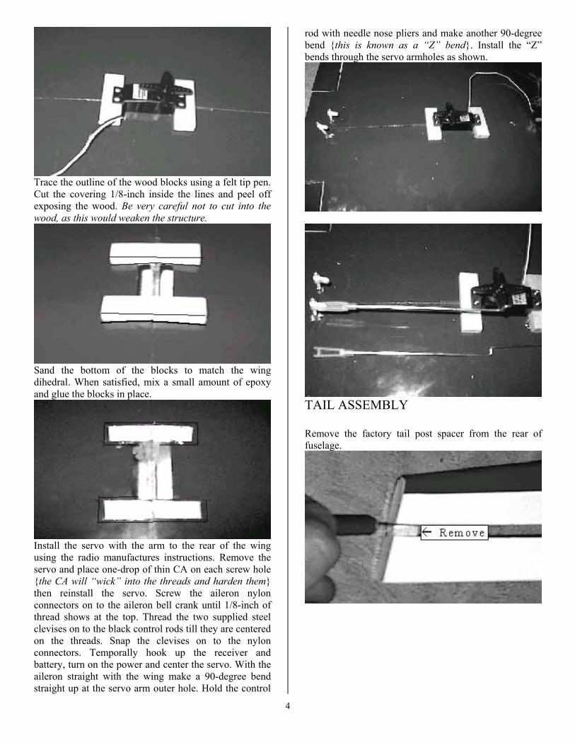
Trace the outline of the wood blocks using a felt tip pen. Cut the covering 1/8-inch inside the lines and peel off exposing the wood. Be very careful not to cut into the wood, as this would weaken the structure.
Sand the bottom of the blocks to match the wing dihedral. When satisfied, mix a small amount of epoxy and glue the blocks in place.
Install the servo with the arm to the rear of the wing using the radio manufactures instructions. Remove the servo and place one-drop of thin CA on each screw hole {the CA will “wick” into the threads and harden them} then reinstall the servo. Screw the aileron nylon connectors on to the aileron bell crank until 1/8-inch of thread shows at the top. Thread the two supplied steel clevises on to the black control rods till they are centered on the threads. Snap the clevises on to the nylon connectors. Temporally hook up the receiver and battery, turn on the power and center the servo. With the aileron straight with the wing make a 90-degree bend straight up at the servo arm outer hole. Hold the control
rod with needle nose pliers and make another 90-degree bend {this is known as a “Z” bend}. Install the “Z” bends through the servo armholes as shown.
TAIL ASSEMBLY Remove the factory tail post spacer from the rear of fuselage.
4
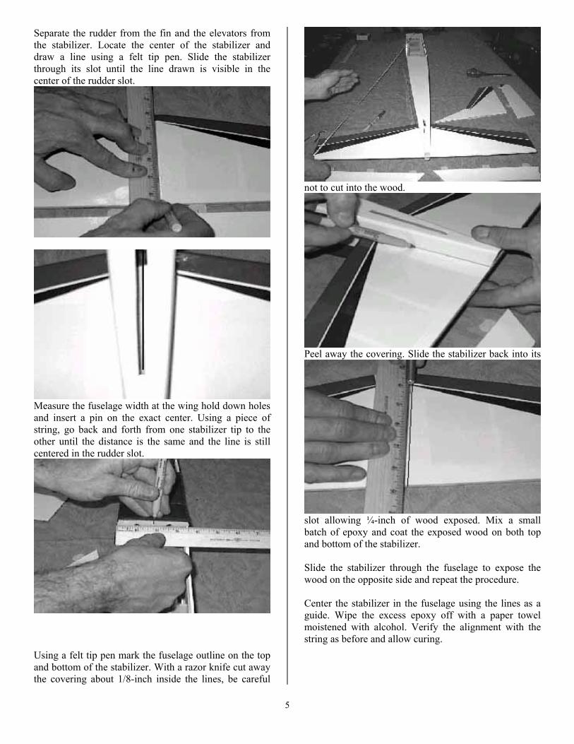
Separate the rudder from the fin and the elevators from the stabilizer. Locate the center of the stabilizer and draw a line using a felt tip pen. Slide the stabilizer through its slot until the line drawn is visible in the center of the rudder slot.
Measure the fuselage width at the wing hold down holes and insert a pin on the exact center. Using a piece of string, go back and forth from one stabilizer tip to the other until the distance is the same and the line is still centered in the rudder slot.
Using a felt tip pen mark the fuselage outline on the top and bottom of the stabilizer. With a razor knife cut away the covering about 1/8-inch inside the lines, be careful
not to cut into the wood.
Peel away the covering. Slide the stabilizer back into its
slot allowing ¼-inch of wood exposed. Mix a small batch of epoxy and coat the exposed wood on both top and bottom of the stabilizer. Slide the stabilizer through the fuselage to expose the wood on the opposite side and repeat the procedure. Center the stabilizer in the fuselage using the lines as a guide. Wipe the excess epoxy off with a paper towel moistened with alcohol. Verify the alignment with the string as before and allow curing.
5
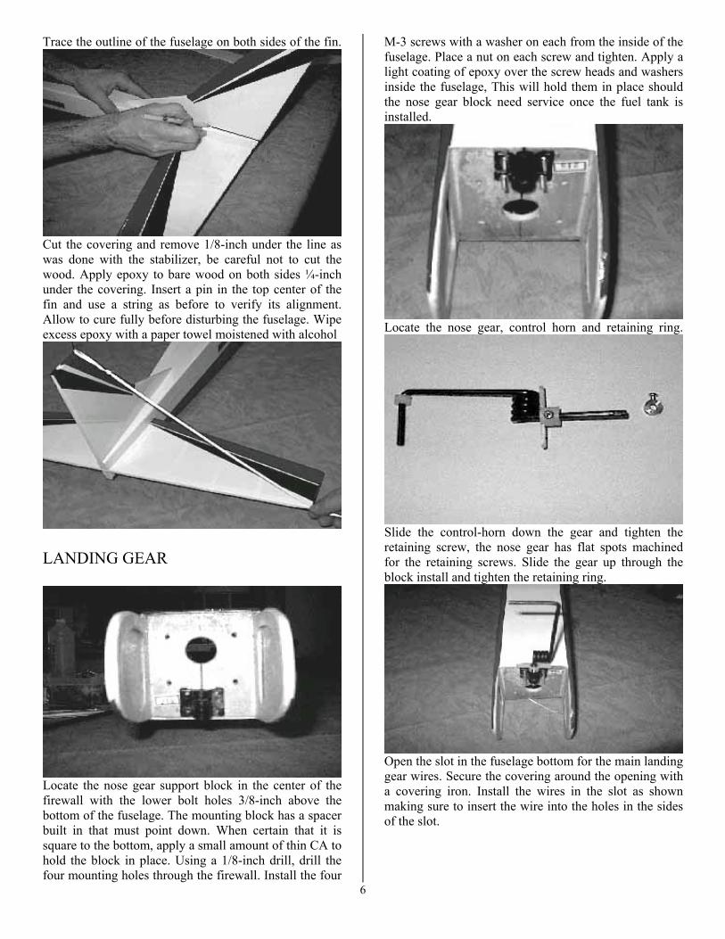
Trace the outline of the fuselage on both sides of the fin.
Cut the covering and remove 1/8-inch under the line as was done with the stabilizer, be careful not to cut the wood. Apply epoxy to bare wood on both sides ¼-inch under the covering. Insert a pin in the top center of the fin and use a string as before to verify its alignment. Allow to cure fully before disturbing the fuselage. Wipe excess epoxy with a paper towel moistened with alcohol
LANDING GEAR
Locate the nose gear support block in the center of the firewall with the lower bolt holes 3/8-inch above the bottom of the fuselage. The mounting block has a spacer built in that must point down. When certain that it is square to the bottom, apply a small amount of thin CA to hold the block in place. Using a 1/8-inch drill, drill the four mounting holes through the firewall. Install the four
M-3 screws with a washer on each from the inside of the fuselage. Place a nut on each screw and tighten. Apply a light coating of epoxy over the screw heads and washers inside the fuselage, This will hold them in place should the nose gear block need service once the fuel tank is installed.
Locate the nose gear, control horn and retaining ring.
Slide the control-horn down the gear and tighten the retaining screw, the nose gear has flat spots machined for the retaining screws. Slide the gear up through the block install and tighten the retaining ring.
6
Open the slot in the fuselage bottom for the main landing gear wires. Secure the covering around the opening with a covering iron. Install the wires in the slot as shown making sure to insert the wire into the holes in the sides of the slot.
Tap the wire to be sure it seated in the slot. Install the two hold-downs with the four 2.5mm wood screws supplied. MOTOR MOUNT
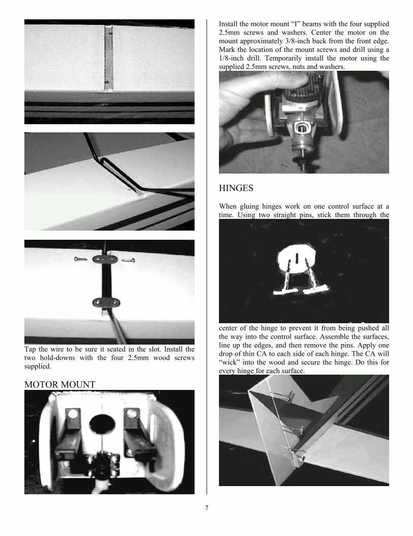
Install the motor mount “I” beams with the four supplied 2.5mm screws and washers. Center the motor on the mount approximately 3/8-inch back from the front edge. Mark the location of the mount screws and drill using a 1/8-inch drill. Temporarily install the motor using the supplied 2.5mm screws, nuts and washers.
HINGES When gluing hinges work on one control surface at a time. Using two straight pins, stick them through the
center of the hinge to prevent it from being pushed all the way into the control surface. Assemble the surfaces, line up the edges, and then remove the pins. Apply one drop of thin CA to each side of each hinge. The CA will “wick” into the wood and secure the hinge. Do this for every hinge for each surface.
7

CONTROLS Open the two control rod exit slots in the right side of the fuselage. Open the top slot only on the left. The slots are located just in front of the leading edge of the stabilizer and can easily be found by shining a flashlight down the inside of the fuselage. Secure the covering around the slots with a covering iron, then apply a small amount of thin CA to the bare wood, this will harden the wood and prevent ware.
Fit and install the servo mount tray as shown with epoxy.
Install the servos following the radio manufactures instructions. Temporally hook up the receiver and
battery, power up the system and center the servos. Be sure to install them so the control arms are as shown in the photo. Fabricate the control rods. Separate the nylon clevises from all five of the control rods. Make a 90-degree bend
at the end of three of the rods 9 7/8-inches from the end with the threads. Cut the short side of the bend leaving 1/8-inch as shown. Note that the elevator wood control rod takes two rods at one end and only one at the other, the rudder takes one at both ends. Incert the bent end of the rod into the hole/slot in the wood control rod. Squeeze gently with pliers to seat the rods in the wood. Wrap the end tightly with thread as shown { it is not nessasary to cover all the wood with the thread }, apply a coat of thin CA and allow to cure. Bend the rods to the dimensions shown in the photo.
For the servo end of the rods, make the bend in the
elevator rod 2 ¼-inches from the threaded end. The rudder will require a “Z” bend located 2 ¾-inches from the bend. Just as done before cut them leaving 1/8-
inch, insert them in the wood, wrap with thread and secure
8

with CA. To incert the elevator rod in the fuselage, Tie a piece of string around the wires as shown, pulling the ends together. Incert the rod in the fuselage, and when the ends are lined up with the exit slots, pull the wire forward to release the ends. attach the servo ends as shown. Screw the nylon clevises on the ends of the rods to the center of the threads. Locate the control horns so that the clevis attach holes are directly over the hinge line when the control surface is straight and the horn is approxometly 1 1/4-inches out from the inside of the stabilizer. Drill the control horn mounting holes using a 3/16-inch drill. Using the supplied screws, go through the control horn and control surface into the supplied tear drop shaped backing plates. Attach the clevis to the control horn. Install the clevises on the servo end and adjust till the control surfaces are straight and even.
STEERING LINKAGE Open the slot in the left bottom of the fuselage {same side as the rudder servo}. Slide the control wire casing
through the slot, through the fuel tank opening and line up with the outside of the rudder servo. Cut a notch in the tank opening where the casing passes through. Sand the casing lightly and epoxy in place. Using the supplied control wire, attach it to the nose gear using a “Z”bend. Slide the wire through its casing, slide the nose gear in its support block and install the
gear retaining ring. With the rudder servo in its neutral position, align the nose gear and mark the wire where it passes under the servo control arm hole. Make a “Z” bend and install the wire in the servo arm on the oppisite side of the rudder. cut a popsicle stick and CA in place as a rear casing support.
With the motor temporally in its mount, drill a 3/16-inch
hole just above the motor mount. Just as was done with the nose gear steering, pass the outer casing through the hole and through the fuel tank opening. Insert the control rod wire between the carb and the servo arm to hold the casing straight {do not make the “Z” bends}. Mark and notch the fuel tank opening, lightly sand the casing and epoxy in place. Remove the motor to prepare for the fuel tank instalation
9

FUEL TANK Slide the long and one short metal tube through the rubber stopper leaving ½-inch sticking out the large side. Slide the small metal plate over the tubes. Bend the long
tube carefully so that it points to the “bubble” at the top of the tank. Slide the rubber line over the short tube.
Cut the line so when assembled the flop weight does not hit the back of the tank. Install the outer metal plate and screw, do not tighten. Install the stopper in the tank but do not tighten the screw. Test fit the tank in the firewall, The outer plate should be snug in the hole in the firewall, Open the hole if nessasery. When satisfied with the fit, apply a ¼-inch bead of RTV silcone around the tank front, press it into place and while holding it there tighten the screw { as the screw tightens the stopper will expand holding it in place till the RTV cures}.
Install two six inch pieces of fuel line. Lable the firewall to avoid mix-up in the future.
Make a “Z” bend in the throttle control wire. Install
the “Z” bend in the Throttle arm on the carburator and slide the other end through the guide hole. Bolt the motor in using the supplied screws, nuts and washers. Install the muffler. Install the fuel and vent line as shown. {It may be nessasary to trim the fuselage for muffler and needle valve clearance} With the radio on, set the throttle closed, close the throttle on the motor. Make sure the servo moves in the correct direction. Mark the control wire at the servo hole,
10

make a “Z” bend as before, Install the wire in the servo arm.
FINAL ASSEMBLY Drill a 3/16 hole through the turtle deck as shown. Cut a 3-inch piece of fuel line at a sharp angle, pass the point of the angle through the hole and pull from the inside
leaving 1-inch sticking out. Place a drop of thin CA around the hole from the inside. Mount the receiver on
the servo tray following the radio manufactures instructions. Pass the antenna through the fuel line exit and secure to the tail with a rubber band {most radio sets come with antenna stops and clips}. Do not pass the antenna through the wing/fuselage joint, the constant
pressure will cut through the antenna and cause a loss of control. Mount the power switch. Install the wheels by first sliding on the nylon spacers, then the wheel and lock collar. Install the propeller and spinner. Be sure the propeller is the correct pitch and diameter for the motor {check the paperwork that came with the motor or contact your local hobby store}. Temporarily install the wing.
BALANCE Balance is extremely important to the performance of the aircraft. Improper balance will make the aircraft difficult if not impossible to trim or fly. DO NOT OMIT THIS STEP!
Turn the airplane over and place a piece of masking tape under the wing on both sides of the fuselage. Measure back from the leading edge of the wing and draw two lines, one at 3-inches and one at 3 1/2-inches on both sides as shown. This is the center of gravity range {C.G.}. Use a balance if you have one or you can support the plane from under the wing with one finger on each side until it balances level. If it balances behind the lines it will be necessary to add weight to the nose, if in front of the lines add weight to the tail {before adding weight try moving the receiver and battery forward or backward in the fuselage}.
11
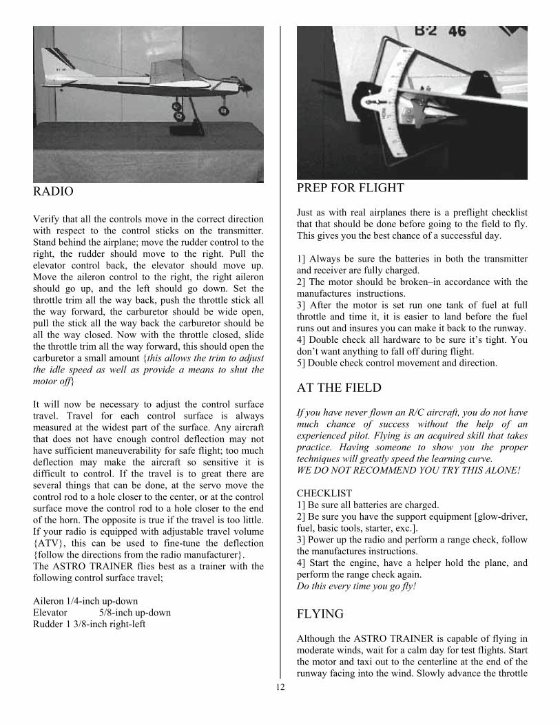
RADIO Verify that all the controls move in the correct direction with respect to the control sticks on the transmitter. Stand behind the airplane; move the rudder control to the right, the rudder should move to the right. Pull the elevator control back, the elevator should move up. Move the aileron control to the right, the right aileron should go up, and the left should go down. Set the throttle trim all the way back, push the throttle stick all the way forward, the carburetor should be wide open, pull the stick all the way back the carburetor should be all the way closed. Now with the throttle closed, slide the throttle trim all the way forward, this should open the carburetor a small amount {this allows the trim to adjust the idle speed as well as provide a means to shut the motor off} It will now be necessary to adjust the control surface travel. Travel for each control surface is always measured at the widest part of the surface. Any aircraft that does not have enough control deflection may not have sufficient maneuverability for safe flight; too much deflection may make the aircraft so sensitive it is difficult to control. If the travel is to great there are several things that can be done, at the servo move the control rod to a hole closer to the center, or at the control surface move the control rod to a hole closer to the end of the horn. The opposite is true if the travel is too little. If your radio is equipped with adjustable travel volume {ATV}, this can be used to fine-tune the deflection {follow the directions from the radio manufacturer}. The ASTRO TRAINER flies best as a trainer with the following control surface travel; Aileron 1/4-inch up-down Elevator 5/8-inch up-down Rudder 1 3/8-inch right-left
PREP FOR FLIGHT Just as with real airplanes there is a preflight checklist that that should be done before going to the field to fly. This gives you the best chance of a successful day. 1] Always be sure the batteries in both the transmitter and receiver are fully charged. 2] The motor should be broken–in accordance with the manufactures instructions. 3] After the motor is set run one tank of fuel at full throttle and time it, it is easier to land before the fuel runs out and insures you can make it back to the runway. 4] Double check all hardware to be sure it’s tight. You don’t want anything to fall off during flight. 5] Double check control movement and direction. AT THE FIELD If you have never flown an R/C aircraft, you do not have much chance of success without the help of an experienced pilot. Flying is an acquired skill that takes practice. Having someone to show you the proper techniques will greatly speed the learning curve. WE DO NOT RECOMMEND YOU TRY THIS ALONE! CHECKLIST 1] Be sure all batteries are charged. 2] Be sure you have the support equipment [glow-driver, fuel, basic tools, starter, exc.]. 3] Power up the radio and perform a range check, follow the manufactures instructions. 4] Start the engine, have a helper hold the plane, and perform the range check again. Do this every time you go fly! FLYING Although the ASTRO TRAINER is capable of flying in moderate winds, wait for a calm day for test flights. Start the motor and taxi out to the centerline at the end of the runway facing into the wind. Slowly advance the throttle
12
holding just a little up-elevator. Maintain directional control with the rudder. After about 40 feet the ASTRO will lift off all by its self. Keep the climb shallow and the turns gentle. Once at a safe altitude, throttle back to about 75% power, fly directly into the wind, using the radio trims, adjust the aileron trim so the wings remain level. Bring the airplane back and once again turn it into the wind, this time adjust the elevator trim to maintain level flight. Adjust the rudder trim till the fuselage is in a straight line with the flight path. It may be necessary to adjust the trims several times as each adjustment affects the others. Be sure to land before the plane runs out of fuel. To land, line the plane up with the end of the runway flying into the wind. Throttle back to about 25% and allow the plane to descend to the end of the runway, once you are sure you made the runway, pull the throttle back to idle and try to hold the plane about 6-inches off the runway. As the plane looses speed it will slowly settle on the runway. If your landing is too long add power as go around, try again. POST FLIGHT TRIM CENTER With the airplane back on the ground, check the trim settings and center them. To do this measure the control surfaces deflection, center the trim on the radio and adjust the control rod to return the surface to the trimmed deflection. For example if after the flight the rudder is 1/8-inch to the right of center, center the radio trim and adjust the control rod so the rudder is once again 1/8-inchto the right. By doing this every time you go fly centering the radio trims will result in a good flying aircraft. After you have mastered the basic flying skills the control surface travel may be increased for more response and basic aerobatics flight. The ASTRO TRAINER is capable of loops, rolls, Hammerheads and inverted flight when in the hands of an experienced pilot.
13