assembly manual - kangkeusakangkeusa.com/instructions/pitts python manual.pdf · pitts python arf...
TRANSCRIPT

Pitts Python
ARF
ASSEMBLY MANUAL
Kangke Industrial USA, Inc.
49 E. Industry CT, Unit N, Deer Park, NY 11729
http://www.kangkeusa.com E-mail: [email protected]
Tel: 1-631-274-3058 Fax: 1-631-274-3296
This manual is the sole property of Kangke Industrial USA, Inc. Reproducing any part without the consent
of Kangke Industrial USA, Inc. is a lawful violation.
Warranty: Kangke Industrial USA Inc. guarantees the kit to be free of defects in both material and
workmanship at the date of purchase. This warranty does not cover any parts damaged by use or
modifications. In no case shall Kangke Industrial’s liability exceed the purchase cost of this kit. Since
Kangke Industrial has no control of final assembly and material used by user for final assembly, no
liability shall be assumed or accepted for any damage resulting from the use by user of final user-
assembled products. This kit has been flight test for normal use. If the plane will be used for extremely
high stress flying, the modeler is responsible for reinforcing the high stress points. Inspect this kit
immediately after receiving it, report any missing and damaged parts within 7 business days otherwise
the claim may be denied.

1
Congratulations!
Kangke Industrial USA, Inc. brings you one of the finest ARF models available. Skilled
craftsmen combined with top grade materials and precision jigs have all come together to
produce an aircraft with outstanding flight qualities. If you follow the directions carefully
the performance of this aircraft will surely please you.
WARNING! As model aircraft gets larger and more powerful, the risk for injury increases.
Kangke’s extensive testing procedures insure a high quality kit that has gone through many
steps to provide you with a safe reliable airframe. Nothing we can do, however, will make
up for poor assembly or irresponsible behavior at the field. A model of this size traveling at
80 MPH contains enough energy that if it were to contact another person, the injuries
would be extensive, possibly fatal. The safe operation of this model is your responsibility
and yours alone. If you are a beginner or have never flown a model of this size and power,
you should not make the attempt without the help of an experienced pilot.
Specifications:
Length 69 in.
Wing Span
Top Wing 73 in.
Bottom Wing 70 in.
Wing Area 1790 sq. in.
Weight 18-20 lbs.
Engine
- (Gas) 50 – 70 cc.
Kit Contents:
Fuselage 1
Wing panel 4
Ailerons 4
Cowling 1
Canopy 1
Main Gear 1
Stabilizer 1
Elevator 2
Fin 1
Rudder 1
Servo mount 1
Tail gear 1
Tail wheel 1
Control horn 8
Hardware pack 1
Manual 1
Wheel gear & pants 1
Wing tube 3
Cowl bottom pan 1
Fuse gear cover 1
The following additional items will also be needed to build the Pitts Python:
HOBBY ITEMS:
Radio 4-ch min.8-9 servos
4-40 Control rods
Fuel line 20-inches
Engine
Muffler
Fuel Tank
3 ½ in. wheels
Robart Hinges – see next
page
125 lb fishing line for
flying wires.
HOUSEHOLD ITEMS:
4 oz. 60-min. epoxy
Popsicle sticks
Hobby knife
Thin CA .5 oz.
Med. CA 1 oz.
Paper towels
Alcohol / Acetone
Ruler
Felt tip pen
Screw drivers
Pliers
Masking tape
Various drill bits
2
.
IMPORTANT – PLEASE READ
BEFORE YOU GO ANY FURTHER, THERE ARE A FEW
ITEMS THAT WE WISH TO BRING TO YOUR ATTENTION .
SINCE THE MANUAL WAS CREATED, THERE HAS BEEN A LOT OF REAL
WORLD FLIGHT TESTING PERFORMED BY A NUMBER OF DIFFERENT OWNER/
PILOTS OVER A PERIOD OF MONTHS.
THEIR FINDINGS AND RECOMMENDATIONS ARE AS FOLLOWS:-
1. IF USING AN ENGINE LARGER THEN 50CC THEN FLYING WIRES
ARE RECOMMENDED. WHILE THE WIRE MATERIAL IS NOT
INCLUDED WITH THE KIT, SUITABLE FLYING WIRES CAN BE
CONSTRUCTED FROM 125 LB FISHING LINE. YOU WILL REQUIRE TO
PURCHASE LINE, CLEVISES AND LINE/CLEVIS CONNECTERS.
2. ALSO, WHILE THE CA TYPE HINGES ARE SATISFACTORY FOR A
50CC POWERED AIRCRAFT, IT IS STRONGLY RECOMMENDED HAT
YOU USE ROBART ¼ SCALE STEEL HINGED POINT HINGES FOR
AIRCRAFT POWERED BY STONGER ENGINES.
They are simply to install and installation instructions are included with the
point hinges. A drill jig is also included with most hinge packages.
3. THE INDICATED CG IS A GREAT STARTING POINT; HOWEVER YOU
MAY MOVE THE CG BACK, A LITTLE AT A TIME UP TO 1 INCH. BUT
BE WARE, WHILE A REARWARD CG IS GREAT FOR 3D MANUVERS,
THE AIRCRAFT COULD BECOME UNSTABLE.
4. IT IS SUGGESTED THAT YOU SET UP YOUR RADIO EXPODENTIAL
SETTINGS TO 45 OR GREATER. JUST REMEMBER THAT WITH 4
ACTIVE AILERONS, THE PITTS IS VERY REACTIVE TO INPUT.
Now, let’s get back to the manual. I hope you enjoy this building and flying
experience.

3
SERVOS
Because of the size and weight of the Pitts Python, standard servos do not produce enough
torque for high performance aerobatics or 3-D flight. The following are the minimum
torque requirements for this level of performance:
Ailerons: 80 oz-in.
Elevators: 80 oz-in.
Rudder: 100 oz-in.
Throttle: Standard servo
Choke: Standard servo
CAUTIONS
Gas engines, because of the ignition systems, require some special care. The ignition is
capable of producing radio interference that can shorten the range of the radio gear.
To help minimize these problems use the following recommendations: Never use a solid
wire for throttle control, use Nyrod or other plastic nonconductor. Keep all radio gear at
least 12 inches from all ignition components, such as battery, switches, wiring and the unit
itself. If a servo is used to operate the ignition on/off switch, do not mount the switch at the
servo, instead use a piece of Nyrod and a remote switch bracket. Be sure spark plug wires
are shielded and the shield is properly grounded to the engine. Follow the engine
manufactures instructions. Large powerful servos have a higher power consumption rate
than standard servos, for this reason it is important the battery selected be capable of
supplying the required amperage. The switch harness must also be of the heavy-duty type.
A lightweight switch may overheat and fail under high loads.
ASSEMBLY
If you are familiar with the assembly of ARF type airplanes, you will find the following
assembly sequence to be unusual. The sequence was designed to speed assembly by
incorporating the radio gear installation in the workflow. Please follow the assembly
instructions as written. The Pitts Python will take approximately 25 hours to complete
Read each step of the instructions carefully. Be sure you understand what is required and
what the procedure is before you glue or cut anything. How well you assemble this model
will have a direct effect on its flight characteristics. In several sections, we have added
HINTS to assist in construction
PLEASE also note:- A Fuel Tank has Not been included due to the fact that a variety of
engines can be used, each one requiring a different tank size to achieve desired flight times.
Also, we have not included wheels. It has been found that most modelers who construct
this size of aircraft throw away the kit included wheels and install their own.
4
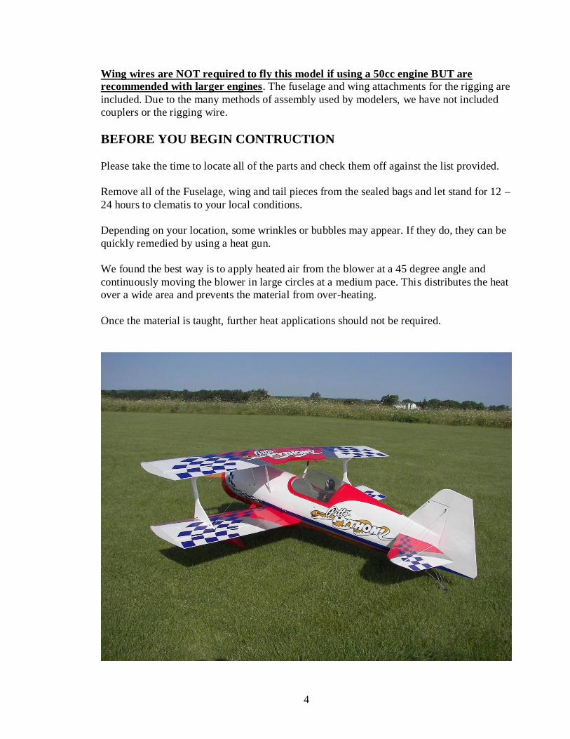
Wing wires are NOT required to fly this model if using a 50cc engine BUT are
recommended with larger engines. The fuselage and wing attachments for the rigging are
included. Due to the many methods of assembly used by modelers, we have not included
couplers or the rigging wire.
BEFORE YOU BEGIN CONTRUCTION
Please take the time to locate all of the parts and check them off against the list provided.
Remove all of the Fuselage, wing and tail pieces from the sealed bags and let stand for 12 –
24 hours to clematis to your local conditions.
Depending on your location, some wrinkles or bubbles may appear. If they do, they can be
quickly remedied by using a heat gun.
We found the best way is to apply heated air from the blower at a 45 degree angle and
continuously moving the blower in large circles at a medium pace. This distributes the heat
over a wide area and prevents the material from over-heating.
Once the material is taught, further heat applications should not be required.

5
WING ASSEMBLY
This sequence will allow for fast assembly of the
wing assemblies.
Assemble the ailerons to the wing panels as
follows:-(Larger engine planes use ROBART
POINT HINGES)
Remove ailerons and hinges from panels.
Place T Pins in hinges and insert hinges into
ailerons.
Carefully attach ailerons to wing panels, aligning
the ailerons with wing panel ends.
Remove pins and close hinge gap.
Carefully glue hinges using THIN CA. Glue top
and bottom sides of each hinge. Let stand for 5
minutes, then pull to ensure that the ailerons are
firmly attached.
Affix servos with required extensions.
Attach Control Horn as shown using the 3 small
screws.
Attach horn to servo using a 4-40 control rod and
supplied control rod connector.
At the servo end, I bent the rod and used a
keeper. This method is simple and secure.
Locate and install 8 – 3 X 18mm bolts in outer
wing panels at strut locations.
Locate and install 2 – 4 X 30mm and 2 – 4 X 20
mm bolts in center section of top wing.
(We suggest that you trial fit the bolts at this
time to ensure easy assembly later on. I used a
bit of light oil on bolts to lubricate.)
Insert upper wing tubes into center and outer
panels and ensure a perfect tight fit.
6
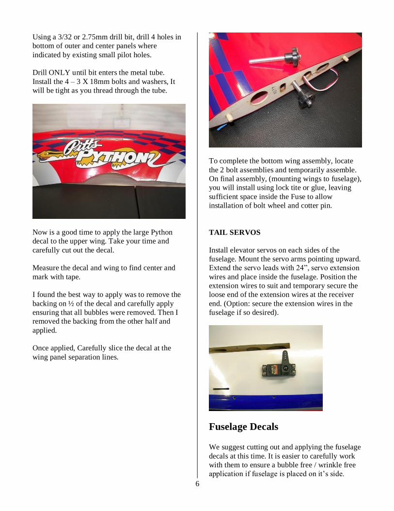
Using a 3/32 or 2.75mm drill bit, drill 4 holes in
bottom of outer and center panels where
indicated by existing small pilot holes.
Drill ONLY until bit enters the metal tube.
Install the 4 – 3 X 18mm bolts and washers, It
will be tight as you thread through the tube.
Now is a good time to apply the large Python
decal to the upper wing. Take your time and
carefully cut out the decal.
Measure the decal and wing to find center and
mark with tape.
I found the best way to apply was to remove the
backing on ½ of the decal and carefully apply
ensuring that all bubbles were removed. Then I
removed the backing from the other half and
applied.
Once applied, Carefully slice the decal at the
wing panel separation lines.
To complete the bottom wing assembly, locate
the 2 bolt assemblies and temporarily assemble.
On final assembly, (mounting wings to fuselage),
you will install using lock tite or glue, leaving
sufficient space inside the Fuse to allow
installation of bolt wheel and cotter pin.
TAIL SERVOS
Install elevator servos on each sides of the
fuselage. Mount the servo arms pointing upward.
Extend the servo leads with 24”, servo extension
wires and place inside the fuselage. Position the
extension wires to suit and temporary secure the
loose end of the extension wires at the receiver
end. (Option: secure the extension wires in the
fuselage if so desired).
Fuselage Decals We suggest cutting out and applying the fuselage
decals at this time. It is easier to carefully work
with them to ensure a bubble free / wrinkle free
application if fuselage is placed on it’s side.
7
Take your time cutting out and applying decals.
It is time well spent.
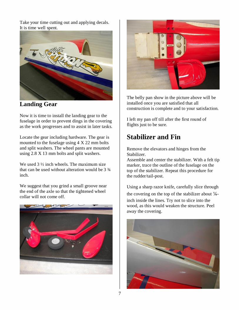
Landing Gear
Now it is time to install the landing gear to the
fuselage in order to prevent dings in the covering
as the work progresses and to assist in later tasks.
Locate the gear including hardware. The gear is
mounted to the fuselage using 4 X 22 mm bolts
and split washers. The wheel pants are mounted
using 2.8 X 13 mm bolts and split washers.
We used 3 ½ inch wheels. The maximum size
that can be used without alteration would be 3 ¾
inch.
We suggest that you grind a small groove near
the end of the axle so that the tightened wheel
collar will not come off.
The belly pan show in the picture above will be
installed once you are satisfied that all
construction is complete and to your satisfaction.
I left my pan off till after the first round of
flights just to be sure.
Stabilizer and Fin
Remove the elevators and hinges from the
Stabilizer.
Assemble and center the stabilizer. With a felt tip
marker, trace the outline of the fuselage on the
top of the stabilizer. Repeat this procedure for
the rudder/tail-post.
Using a sharp razor knife, carefully slice through
the covering on the top of the stabilizer about ¼-
inch inside the lines. Try not to slice into the
wood, as this would weaken the structure. Peel
away the covering.

8
Insert a pin in the center of the nose deck. Use a
string or a ruler, measuring from pin to stabilizer
outside back edges to square up the stabilizer.
Our measurement worked out to be 50 ½ inches.
Also ensure that the length of the rear stabilizer
edge from Fuselage to outer edge is exactly the
same. ( 14 inches )
Assemble the stabilizer and its mating surface
using the drawn lines for alignment. Verify the
alignment with the string or ruler.
Apply 30 minute epoxy to fix the stabilizer to the
fuselage.
Coat the rudder-fin mating surface with 30-min
epoxy. Carefully insert the rudder/tail-post.
Clean the excess epoxy with a paper towel
moistened with alcohol. Allow the epoxy to cure.
RUDDER
Insert hinges with pins into rudder.
Temporarily mount rudder to fin and mark
control horn locations which should line up with
line exits on each side of fuselage.
Attach the 2 control horn assemblies.
Attach the rudder portion of the tail wheel
assembly to bottom of rudder.
Attach rudder to fin, ensuring proper alignment
with fin, leaving about 3/32 inch gap between
top of fin and rudder .
Remove pins from hinges, ensure a snug fit and
apply thin CA to both sides of hinges.
PULL-PULL RUDER SYSTEM
Install rudder servo in fuselage as shown.
The servo arm should be 2 ¼ inches long to
match the distance between the rudder horn /
clevis attachment points.
Prepare the exterior rudder end of each required
cable. You will need approximately 38 inches of
cable material for each rudder pull line. That is
sufficient to allow interior hook up without
struggling.
Refer to the following picture. Notice how the
line is double looped and crimped.

9
Set and crimp permanently the linkages at the
rudder end of the cable.
Temporarily connect rudder servo to your radio
system to find and hold center. Ensure that Tx
trims are neutral.
You also should consider blocking the rudder in
neutral with a couple of clamps and balsa sticks,
Now complete the connection of the pull / pull
system to the rudder.
Finally, complete the rudder control / tail wheel
assembly by installing the 2 springs between the
tail wheel and rudder. Ensure that the spring are
secure, however final install should be left until
you have taken a couple of taxi runs.
Fuselage/ Upper Wing Cabanes
Locate the 4 cabane pieces. NOTICE that there
are 2 long and 2 shorter cabanes. The LONG
cabanes are fitted to the rear positions while the
longer ones fit in the front positions.
Slide the cabanes through the slots located in the
fuselage. They fit BEHIND the ply plates.
Using the 8 – 3 mm X 12.75 mm bolts, insert
them in the holes in the ply plate and tighten
them into the metal cabanes. The bolts will “tap”
into the cabanes.
10
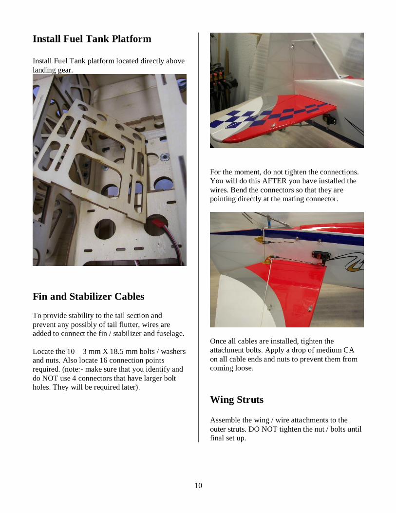
Install Fuel Tank Platform
Install Fuel Tank platform located directly above
landing gear.
Fin and Stabilizer Cables
To provide stability to the tail section and
prevent any possibly of tail flutter, wires are
added to connect the fin / stabilizer and fuselage.
Locate the 10 – 3 mm X 18.5 mm bolts / washers
and nuts. Also locate 16 connection points
required. (note:- make sure that you identify and
do NOT use 4 connectors that have larger bolt
holes. They will be required later).
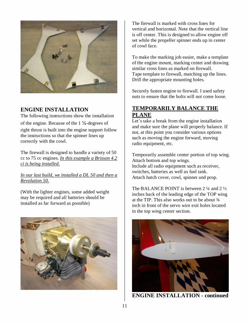
For the moment, do not tighten the connections.
You will do this AFTER you have installed the
wires. Bend the connectors so that they are
pointing directly at the mating connector.
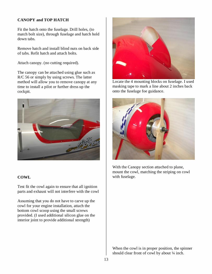
Once all cables are installed, tighten the
attachment bolts. Apply a drop of medium CA
on all cable ends and nuts to prevent them from
coming loose.
Wing Struts Assemble the wing / wire attachments to the
outer struts. DO NOT tighten the nut / bolts until
final set up.
11
ENGINE INSTALLATION The following instructions show the installation
of the engine. Because of the 1 ½-degrees of
right thrust is built into the engine support follow
the instructions so that the spinner lines up
correctly with the cowl.
The firewall is designed to handle a variety of 50
cc to 75 cc engines. In this example a Brisson 4.2
ci is being installed.
In our last build, we installed a DL 50 and then a
Revolution 50.
(With the lighter engines, some added weight
may be required and all batteries should be
installed as far forward as possible)
The firewall is marked with cross lines for
vertical and horizontal. Note that the vertical line
is off center. This is designed to allow engine off
set while the propeller spinner ends up in center
of cowl face.
To make the marking job easier, make a template
of the engine mount, marking center and drawing
similar cross lines as marked on firewall.
Tape template to firewall, matching up the lines.
Drill the appropriate mounting holes.
Securely fasten engine to firewall. I used safety
nuts to ensure that the bolts will not come loose.
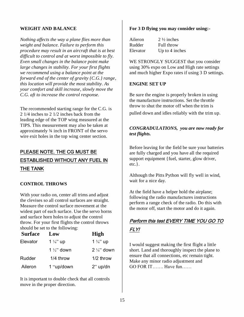
TEMPORARILY BALANCE THE
PLANE Let’s take a break from the engine installation
and make sure the plane will properly balance. If
not, at this point you consider various options
such as moving the engine forward, moving
radio equipment, etc.
Temporarily assemble center portion of top wing.
Attach bottom and top wings.
Include all radio equipment such as receiver,
switches, batteries as well as fuel tank.
Attach hatch cover, cowl, spinner and prop.
The BALANCE POINT is between 2 ¼ and 2 ½
inches back of the leading edge of the TOP wing
at the TIP. This also works out to be about ¾
inch in front of the servo wire exit holes located
in the top wing center section.
ENGINE INSTALLATION - continued

12
For engines with separate ignitions, you can
either install the unit inside the firewall box or
attached to the firebox sidewall. We suggest you
wrap it in foam to prevent vibration damage and
If attached to sidewall, use plastic ties.
Depending on your engine set up, you may wish
to install a choke servo rather than manually
operate it.
PLEASE NOTE:- Both AMA and MAAC
state that you MUST be able to shut off the
engine remotely using another method other
then Throttle.
If you do not control the choke using the radio,
then you will be required to install some form of
interrupter to the electrical portion of the engine.
Install the throttle servo. Servo positions are
provided on either side of the fuselage interior.
Pick the side that best matches your carburetor
location.
Install the Throttle linkage. We recommend that
you use Nyrod for this application. It has been
reported that some radios may be affected by
engine ignition noise.
Connect the throttle and choke servos
temporarily to your receiver and ensure proper
operation. Quite often, you may have to limit the
servo arm throws by adjusting your Tx settings.
Radio Installation
You have previously balanced the plane by
placing the receiver, batteries, etc. loosely in the
fuselage. Now it is time to put everything in
place.
Locate and install switches for radio and ignition.
To operate the upper ailerons, run a 12 inch
extension up the inside of each of the rear
cabanes. I used white electrical tape to bind and
hide the wires.
Another option to the extensions is a “Y” harness
with 12 inch leads.
Depending upon your radio, you should consider
either using separate channels for left and right
ailerons, you using a system of 3 “Y’ harnesses
into one channel. You will also have to consider
using 2 channels for elevator or purchasing a
“servo reversing Y” harness to use 1 channel.
Wrap your receiver and batteries in foam and
mount securely. ( For this build, the batteries
were located in the side wall packet forward of
the front cabane.)
For radios that use long wire antennae, a plastic
tube is located in the interior of the fuselage.
13
CANOPY and TOP HATCH
Fit the hatch onto the fuselage. Drill holes, (to
match bolt size), through fuselage and hatch hold
down tabs.
Remove hatch and install blind nuts on back side
of tabs. Refit hatch and attach bolts.
Attach canopy. (no cutting required).
The canopy can be attached using glue such as
R/C 56 or simply by using screws. The latter
method will allow you to remove canopy at any
time to install a pilot or further dress up the
cockpit.
COWL
Test fit the cowl again to ensure that all ignition
parts and exhaust will not interfere with the cowl
Assuming that you do not have to carve up the
cowl for your engine installation, attach the
bottom cowl scoop using the small screws
provided. (I used additional silicon glue on the
interior joint to provide additional strength)
Locate the 4 mounting blocks on fuselage. I used
masking tape to mark a line about 2 inches back
onto the fuselage foe guidance.
With the Canopy section attached to plane,
mount the cowl, matching the striping on cowl
with fuselage.
When the cowl is in proper position, the spinner
should clear front of cowl by about ¼ inch.

14
FINAL ASSEMBLY
Additional paint and exterior trim such as decals
and numbers may be added. Whatever details
you add keep in mind that weight is the enemy of
a high performance aircraft. KEEP IT LIGHT.
Attach upper wing center section to Cabanes.
The longer bolts are used to attach the front
cabanes. Also attach the wing wire connections
with the bolts.
Attach lower wings, and establish required
length of attachment threaded rod. We allowed
1¼ inch of length and epoxied the threaded rod
into the wing, making sure that the keeper hole
was vertical.
Once the attachments are solid, complete
installation with nut assemblies and cotter pins.
Attach outer panels of top wing, secure by
inserting bolts into the pre-drilled holes on
under-side of wing center section.
Install wing struts. Tighten all strut bolts.
DON’T FORGET THE WING
WIRES IF ENGINE IS
GREATER THEN 50CC
That completes the assembly process.
CONGRATULATIONS
15
WEIGHT AND BALANCE
Nothing affects the way a plane flies more than
weight and balance. Failure to perform this
procedure may result in an aircraft that is at best
difficult to control and at worst impossible to fly.
Even small changes in the balance point make
large changes in stability. For your first flights
we recommend using a balance point at the
forward end of the center of gravity {C.G.} range,
this location will provide the most stability. As
your comfort and skill increase, slowly move the
C.G. aft to increase the control response.
The recommended starting range for the C.G. is
2 1/4 inches to 2 1/2 inches back from the
leading edge of the TOP wing measured at the
TIPS. This measurement may also be taken at
approximately ¾ inch in FRONT of the servo
wire exit holes in the top wing center section.
PLEASE NOTE. THE CG MUST BE
ESTABLISHED WITHOUT ANY FUEL IN
THE TANK
CONTROL THROWS
With your radio on, center all trims and adjust
the clevises so all control surfaces are straight.
Measure the control surface movement at the
widest part of each surface. Use the servo horns
and surface horn holes to adjust the control
throw. For your first flights the control throws
should be set to the following:
Surface Low High
Elevator 1 ¼” up 1 ¾” up
1 ½” down 2 ¼” down
Rudder 1/4 throw 1/2 throw
Aileron 1 “up/down 2” up/dn
It is important to double check that all controls
move in the proper direction.
For 3 D flying you may consider using:-
Aileron 2 ½ inches
Rudder Full throw
Elevator Up to 4 inches
WE STRONGLY SUGGEST that you consider
using 30% expo on Low and High rate settings
and much higher Expo rates if using 3 D settings.
ENGINE SET UP
Be sure the engine is properly broken in using
the manufacture instructions. Set the throttle
throw to shut the motor off when the trim is
pulled down and idles reliably with the trim up.
CONGRADULATIONS, you are now ready for
test flights.
Before leaving for the field be sure your batteries
are fully charged and you have all the required
support equipment {fuel, starter, glow driver,
etc.}.
Although the Pitts Python will fly well in wind,
wait for a nice day.
At the field have a helper hold the airplane;
following the radio manufactures instructions
perform a range check of the radio. Do this with
the motor off, start the motor and do it again.
Perform this test EVERY TIME YOU GO TO
FLY!
I would suggest making the first flight a little
short. Land and thoroughly inspect the plane to
ensure that all connections, etc remain tight.
Make any minor radio adjustment and
GO FOR IT……. Have fun……
16
TRIMING BASIC FLIGHT
The Pitts Python is NOT a trainer. A true
aerobatic aircraft, it goes only where you point it
and will not recover to level flight without
control input. If you do not have high
performance experience seek the help of
someone who does.
Line up on the center of the runway and slowly
open the throttle, using the rudder to maintain
directional control. Once the tail is up apply a
little up elevator and allow the plane to gently lift
off the runway. Keep the climb angle and turns
shallow until you reach a safe altitude. Reduce
the throttle to about 60% power. With the
airplane flying away from you adjust the radio
aileron trim tab till the wing stays level. Turn
and line up the plane with the runway. Adjust the
elevator trim till the plane maintains level flight.
Once again with the airplane flying away from
you adjust the rudder trim till the fuselage tracks
straight {it may be necessary to correct the
aileron trim after this procedure}.
Continue to fly and trim until the aircraft is
tracking well, land before the fuel runs out.
Carry a little power on final approach until over
the end of the runway, then cut power to idle,
hold the plane just off the runway till the
airspeed bleeds off and the plane settles on. If the
landing is too long, add power go around and try
again, don’t try to force it to the ground.
Now its time to zero out the trims. To do this
measure the control location, center the trim tab
on the radio and adjust the servo horn for large
changes, the control clevis for small changes. For
example if after the flight the rudder is 3/16 inch
to the right, center the radio trim and adjust the
clevis till the rudder once again measures 3/16
right. By doing this whenever you fly, setting the
radio trims at center will result in a well-trimmed
plane. Increase the control travel, as you become
more familiar with the flight characteristics until
loops take about 50 feet and knife-edge can be
maintained with 80% stick deflection. Final roll
rate should be 300-360 degrees per second.
If you have followed the procedures in this
Manuel you will now be rewarded with one of
the finest flying sport models available. All
aerobatic maneuvers are at your fingertips and
the aircraft will perform them with ease. No
further trim work will be required until you are
ready for unlimited and advanced 3-D flights.
Before attempting any of the
ADVANCED FLIGHT TRIM procedures you
must be completely comfortable with inverted
and knife-edge flight. The following trim
sequence is very time consuming and you may
not be able to complete it in one day. Every
change made during this procedure will affect
all others so it will be necessary to start the
procedure from the beginning after each
adjustment.
17
ADVANCED FLIGHT TRIM
All the following tests should be performed at
80% power unless noted.
C.G. Fine Tuning:
Roll inverted, neutral elevator to two clicks of
down trim, if the model descends move the C.G.
aft. If the model climbs move the C.G. forward.
C.G. movement should be no more than ¼” at a
time.
Engine Thrust Angle Right/Left:
On a low pass 50% power directly into the wind,
go to 80% power and pull to a vertical line at the
same time. As the model slows do not correct the
path with rudder. If the model yaws right add
1/16” shims under the right side motor mount
bolts at the firewall. If the model yaws left place
the shims under the left side.
Main Wing Incidence:
Roll to knife-edge flight, if down elevator is
required to maintain a straight line, shim the
back of the main wing 1/8” at a time till the
elevator is neutral. If up elevator is required
shave the rear of the wing saddle 1/8” at a time.
Engine Thrust Angle Up/Down:
On a low pass 50% power crosswind, go to 80%
power and pull vertical at the same time. As the
model slows do not correct path with elevator. If
the model tries to loop add 1/16-inch shims to
the top motor mount bolts. If the model tries to
push over to the wheel side, add 1/16” shims
to the lower motor mount bolts.
Wing Tip Weight:
Level flight into the wind, roll inverted neutral
aileron. If one wing drops add weight to the
other wing tip 1/8-ounce at a time.
Elevator Surface Alignment:
Fly away from you directly into any wind, apply
full throttle and pull two consecutive loops.
Model rolls right, raise left elevator, model rolls
left, raise right elevator.
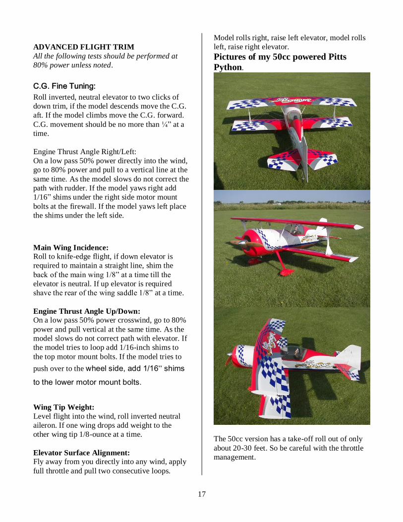
Pictures of my 50cc powered Pitts
Python.
The 50cc version has a take-off roll out of only
about 20-30 feet. So be careful with the throttle
management.