asphalt plant level ii january of module dust … plant 2/06 - module...asphalt plant level ii –...
TRANSCRIPT

Asphalt Plant Level II – January 2009 Page 1 of 25 Module 6 – Dust Collection and Fines Return
Slide 1
January 2009 6 - 1
Module 6
Dust Collectionand Fines Return
ConstructionTrainingQualification Program
Asphalt Plant
Level 2
Slide 2
January 2009 6 - 2
Module 6What you will learn….
• Types of emission/dust control systems• Difference between primary and secondary
collection/collectors• Re-introducing collected dust in the mix• Best Management Practices for consistent
dust return• How dust collection equipment can impact
volumetric properties of the mix
This module will cover modern dust collection equipment on the hot mix plant. You will be introduced to the differences between primary collectors and secondary collectors. A significant amount of information is offered on re-introducing collected fines to the mix, with an emphasis on controlling the fines return on a consistent basis. Fine aggregate gradations have a significant impact on volumetric properties of the mix, and the dust collection and dust return equipment directly relates to volumetric performance.
Slide 3
January 2009 6 - 3
Module 6What you will learn….
• If you have a voids or -200 problem, check dust collection and return system first.
• “Fines on Tour”
You will learn that if you have a voids or –200 content problem with your test results, you are well served to inspect the dust collection and dust return equipment. In a modern hot mix plant, fines released from the aggregate matrix in the dryer go “on tour,” being removed from the aggregate in the hot gas stream, being collected with the dust control equipment, and being returned to the mix with the dust return equipment. This takes time and can get out of balance relative to the rest of the plant

Asphalt Plant Level II – January 2009 Page 2 of 25 Module 6 – Dust Collection and Fines Return
system. Managing that process is critical for proper fines control and consistent test results.
Slide 4
January 2009 6 - 4
The information presented in this section is found …
• “Hot Mix Asphalt Production Facilities”(NHI Course 131044)
• Module 7, pages 7-2 to 7-46
• “Hot Mix Paving Handbook 2000”• Section 12, pages 105-112
The information presented in this section is found in Module 7 (pages 7-2 to 7-46) in NHI Course 131044 “Hot Mix Asphalt Production Facilities,” and in Section 12 (pages 105-112) in the “Hot Mix Paving Handbook 2000.”
Slide 5
January 2009 6 - 5
Dust Control Equipment
No specific department requirements.
Department does not control air quality.
Gradation & volumetric properties of the mix is controlled elsewhere (testing).
There are no FDOT Specifications for dust collection equipment. The Department does not regulate air emissions. Each plant, however, is required to have an air quality permit in good standing in order to function as a business in the State of Florida. The Department’s focus is on mix quality, and is concerned on the gradation and the volumetric properties of the final mix. Dust collection and dust return equipment affects these characteristics; but the provisions for testing and controlling the final mix are outlined in Module 10 and are not specifically associated with the air pollution or emission control equipment.

Asphalt Plant Level II – January 2009 Page 3 of 25 Module 6 – Dust Collection and Fines Return
Slide 6
January 2009 6 - 6
Dust Control Equipment is PositionedBetween the Dryer and the Exhaust Fan
The dust control equipment sits between the dryer and the exhaust fan with the express purpose of cleaning dust from the air stream.
Slide 7
January 2009 6 - 7
Dust Control Equipment
Divided into two different types:
• Primary Collectors• Secondary Collectors
The dust control system is divided into two types of equipment, the primary collector and the secondary collector.
Slide 8
January 2009 6 - 8
Primary Collectors
Several Styles:• Knockout Boxes (used with bag house)• Single Cyclones • Multiple Cyclones – not discussed
Primary Collectors collect the largest size dust particles (+100 mesh material).
The primary collector will collect the largest size (+100 mesh) dust particles. Primary collectors come in different styles. They vary from knockout boxes, which are least efficient, to multi-tube collectors (old technology). Note: Most modern plants are equipped with baghouses, and use either a knockout box or single cyclone primary collector design, because the baghouse is very efficient at collecting the other small aggregate fractions.

Asphalt Plant Level II – January 2009 Page 4 of 25 Module 6 – Dust Collection and Fines Return
Slide 9
January 2009 6 - 9
Knock-Out BoxPrimary Collector
A knockout box collector is the simplest, and involves an expanded plenum where the dust can slow down, impact a knock-down plate, and change directions. Knock-out boxes operate on three principles, slowing down the air stream, turning the air stream, and impact. All three principles serve to remove dust from the air stream. Collected fines are typically returned directly to the aggregate stream.
Slide 10
January 2009 6 - 10
Knock-Out Box Primary
Collector
This is a picture of the knock out box primary collector on a modern counter-flow drum-mixer plant.
Slide 11
January 2009 6 - 11
Cyclone Primary Collector
A cyclone style primary collector is more efficient than a knock-out box. It will collect a larger quantity of dust and slightly smaller particles. A cyclone functions on principles of expansion (slow the air stream), centrifugal force (swirling air causes dust particles to collect on outside walls), and turning the air stream (the air stream must slow and turn to exit the tube in the middle of the collector).

Asphalt Plant Level II – January 2009 Page 5 of 25 Module 6 – Dust Collection and Fines Return
Slide 12
January 2009 6 - 12
Primary Collectors
Must have a seal on the bottom of the primary.
• Keeps exhaust fan from pulling air up the collector and prohibiting dust return
All primary collectors have a seal on the bottom to keep the exhaust fan from pulling air up into the primary. If this happens, then dust collection is inhibited and dust return changes. In order to keep the primary collector functioning, and in order to produce a consistent hot mix product it is imperative that the discharge seal on the primary collector is functioning properly.
Slide 13
January 2009 6 - 13
Gravity Valve or “Flop Gate”
This style of primary seal is a simple gravity valve, also called a tipping valve or “flop gate.” A counter-balance weight on the valve keeps it closed. Collected dust sits on top of the valve and pushes it open when the dust weighs enough to overcome the weight of the counter-balance.
Slide 14
January 2009 6 - 14
Rotary Valve or “Airlock”
A rotary valve or “airlock” is a more consistent fines return device. This type of valve turns constantly with a motor, returning collected dust, but keeps the exhaust fan from pulling air up through the discharge of the primary collector.

Asphalt Plant Level II – January 2009 Page 6 of 25 Module 6 – Dust Collection and Fines Return
Slide 15
January 2009 6 - 15
Primary Collector Dust Return
Typically 100% of the dust is returned to plant:
• Batch plant in the elevator• Drum-mix directly into the mix
Typically 100% of the primary dust is returned to the aggregate stream. In a batch plant, primary dust is usually returned to the bucket elevator. In a drum-mix plant, the fines are returned directly to the mix discharge area.
Slide 16
January 2009 6 - 16
Primary Collector Dust Return in a Batch Plant
Primary
Fines from a primary collector are typically returned directly to the boot of the hot elevator on a batch plant. Fines end up in the “No. 1” or “dust” bin in the tower.
Slide 17
January 2009 6 - 17
Primary Collector Dust Return in a Batch Plant
Primary
This photograph shows fines collected in the primary cyclone being returned directly to the hot elevator. They will end up in the “No. 1” or fines hot bin.

Asphalt Plant Level II – January 2009 Page 7 of 25 Module 6 – Dust Collection and Fines Return
Slide 18
January 2009 6 - 18
Primary Collector Dust Return in a Drum-Mix Plant
PrimaryVeiling Hot Mix also
acts as a Primary
The expanded outlet plenum on a drum-mix plant operates as a knock-out box primary collector. Fines are collected as the air stream slows, is turned, and sometimes encounters a knock-down plate. Fines drop directly into the mix as it exits the drum-mixer. The veiling asphalt in the back of a “parallel-flow” drum-mixer also catches a large percentage of dust from the aggregate and functions much like a primary collector. “Counter-flow” drum-mixers typically have separate primary collectors because asphalt is not veiling in the back of the hot gas stream to catch fines from the dried aggregate.
Slide 19
January 2009 6 - 19
Primary Collector Dust Return in a Drum-Mix Plant
Primaries
This parallel-flow drum-mixer essentially has two primary collectors; the first being the expanded housing on the drum shell, the second being a primary knockout box fitted just prior to the baghouse.

Asphalt Plant Level II – January 2009 Page 8 of 25 Module 6 – Dust Collection and Fines Return
Slide 20
January 2009 6 - 20
Primary Collector Dust Return in a Drum-Mix Plant
Primary
This counter-flow drum-mixer is fitted with a cyclone primary collector prior to the baghouse. Most counter-flow drum-mixers have proper primary collectors because there is no veiling of hot mix in the gas stream to catch particulate. Without a primary collector the baghouse would become overloaded. Fines from the primary in this plant are dropped by chute through a rotary valve to a screw conveyor that carries them together with the baghouse fines to the mixing area of the drum-mixer.
Slide 21
January 2009 6 - 21
Best Management PracticesPrimary Collectors
• Inspect primary dust gate or airlock on regular basis
• Inspect for holes in knock-down plate • Inspect for holes in primary tube
(all conditions inhibit dust return and mix quality … depending on how baghouse fines are beinghandled …100% returned? Partially returned?)
Primary collectors wear and must be inspected and repaired on a regular basis to provide consistent fines return. Inspection points include dust return valves, knock-down plates and primary tubes. Worn valves can keep dust from being returned. Worn knock-down plates or tubes can cause the collector to keep from functioning as a primary because the air passes directly through the plate or tube, which now acts like ductwork without slowing the air down.
Slide 22
January 2009 6 - 22
Secondary Collectors
Two Types:
• Scrubbers (wet collection)• Baghouses (dry collection)
Secondary collectors are the largest and most efficient collectors. They collect the -200 mesh material from the air stream, and are largely responsible for the plant meeting air quality guidelines. Secondary collectors are divided into two types: scrubbers or wet collectors and baghouses or dry collectors. Wet collectors are very rare as baghouse collectors have replaced most existing systems and are standard on new plants and retrofits. Wet scrubbers will not be

Asphalt Plant Level II – January 2009 Page 9 of 25 Module 6 – Dust Collection and Fines Return
discussed further in this course.
Slide 23
January 2009 6 - 23
Baghouses
Principles of collection are:
Dry filtration….dust is collected on afabric filter supported by a cage
(fines collected are re-usable in the mix if the gradation in the job mix formula allows)
Baghouses have become the most popular type secondary collector on hot-mix plants for a variety of reasons: they can consistently meet dust emissions regulations; they do not require settling ponds; and the fines collected can be re-used back into the mix. Baghouses operate under principles of dry collection. Dust is collected on the outside of the filter bags, removed, and if the job mix formula allows, can be returned to the hot mix product. The vast majority of asphalt plants in Florida use baghouse collectors.
Slide 24
January 2009 6 - 24
Cutaway View of Typical Baghouse
DustCollection
Hopper
“DirtyAir
Plenum”
“CleanAir
Plenum”
The baghouse has three key sections, the dirty air side or “dirty air plenum,” the clean air side or “clean air plenum,” and the dust collection hopper. This illustration shows all three, along with the dust return screw in the hopper.

Asphalt Plant Level II – January 2009 Page 10 of 25 Module 6 – Dust Collection and Fines Return
Slide 25
January 2009 6 - 25
Path of Air Through a Typical Baghouse
(1) Dust-laden air enters on the “dirty air” side of the baghouse
DustfromDryer
This illustration shows the path of the process gas stream through the baghouse. Dust laden air from the dryer enters the “dirty air plenum.”
Slide 26
January 2009 6 - 26
Path of Air Through a Typical Baghouse
(1) Dust-laden air enters on the “dirty air” side of the baghouse
(2) Dust is filtered out by the bags
The dust is filtered from the gas stream by the bags.
Slide 27
January 2009 6 - 27
Path of Air Through a Typical Baghouse
(1) Dust-laden air enters on the “dirty air” side of the baghouse
(2) Dust is filtered out by the bags
(3) Clean air exits up through the top of the bags and out the exhaust fan
ExhaustFan
Clean air exits out from the bag into the clean air plenum. The exhaust fan, which is creating the hot gas stream in the dryer together with the burner (again, see Module 5), is connected to this clean air plenum, typically with duct work from the top of the baghouse to the fan sitting on the ground. Clean air from the dryer, exits the stack.

Asphalt Plant Level II – January 2009 Page 11 of 25 Module 6 – Dust Collection and Fines Return
Slide 28
January 2009 6 - 28
This illustration shows how the dust is filtered out by the bag, and the bag is cleaned. Dust is collected on the outside of the filter bags, then cleaning air is forced back through the bag in the opposite direction, removing the dust cake from the bag. This cleaning air can be compressed air (pulse jet cleaning), a cleaning fan (reverse air cleaning), or a mechanism that allows the exhaust fan to pull outside air back through the bag to clean it (differential pressure cleaning). While plant personnel have their preferences for different cleaning techniques, for the purpose of this program the differences are not important.
Slide 29
January 2009 6 - 29
This photograph shows the same baghouse shown in the cutaway drawing installed on a drum-mix plant. With this baghouse, the clean air plenum has compressed air cleaning and is a darker gray in color. The dirty air plenum is the large section with ribbed walls, and is lighter gray. The hopper and dust return screw is clearly seen. Fines from the hopper are being returned directly to an injection screw on this drum-mixer plant.

Asphalt Plant Level II – January 2009 Page 12 of 25 Module 6 – Dust Collection and Fines Return
Slide 30
January 2009 6 - 30
Regardless the style of cleaning, the condition of the “dust cake” on the bag is
monitored with a “magnahelic” gauge
Gauge is always found on the control panelwith a duplicate often found on baghouse
Regardless of the style of cleaning, the condition of the “dust cake” on the bag is indicated to the operator with a gauge known as a magnahelic gauge that measures the condition of the “dust cake” on the bag. This gauge is always found on the control panel, and sometimes a duplicate gauge is found on the baghouse, as is shown here. In some highly computerized plants, this value is also displayed on the main plant control screen, as is shown in the photograph on the left.
Slide 31
January 2009 6 - 31
This gauge measures what is referred to as the “pressure drop” across the baghouse
The gauge or value measures what is referred to as the “pressure drop” across the baghouse.
Slide 32
January 2009 6 - 32
“Pressure drop” across the baghouse is the differential system pressure between the
“clean air plenum” and the “dirty air plenum”
The “pressure drop” across the baghouse is the differential pressure to atmosphere between the dirty side and the clean side of the collector, or the difference between the “dirty air plenum” and the “clean air plenum.”

Asphalt Plant Level II – January 2009 Page 13 of 25 Module 6 – Dust Collection and Fines Return
Slide 33
January 2009 6 - 33
“Pressure drop” across the baghouse representsthe differential system pressure across the bag and represents the thickness of the dust cake
The “pressure drop” or differential pressure across the baghouse really represents the differential pressure across the bag, and therefore the thickness of the dust cake. This differential pressure, or pressure drop, is commonly referred to in plant circles as “Delta P,” delta (Δ) being the Greek letter that is used in the scientific community to represent “differential”. “Delta P” or “ΔP,” then, is the differential pressure or the “pressure drop” across the collector and bag.
Slide 34
January 2009 6 - 34
Managing this “pressure drop” (ΔP) is a key element in fines collection consistency
And is the responsibility of the operator
Managing the ΔP, or “pressure drop” is a key element in managing consistent fines collection, and is the responsibility of the operator.
Slide 35
January 2009 6 - 35
Best Management PracticesManaging the ΔP
• Adjust cleaning mechanism for a consistent ΔP
–Should not vary drastically – 2” to 5” is typical
–This helps ensure consistent collection and is first step in consistent dust return
–This helps avoid varying dust return percentages by ensuring consistent collection
The operator will adjust the cleaning cycle of the baghouse to maintain a consistent pressure drop or ΔP. This ensures consistent fines collection. By maintaining a consistent number on the magnahelic gauge, the operator is really maintaining a consistent dust cake. That is, dust is being collected and cleaned from the bag at a consistent rate, ensuring that the level of dust that is entering the collector is being cleaned and is being transferred to the fines return hopper. By maintaining a consistent ΔP

Asphalt Plant Level II – January 2009 Page 14 of 25 Module 6 – Dust Collection and Fines Return
or pressure drop, the operator avoids varying dust percentages that can occur from varying the level of dust cake then releasing it to the hopper. If the operator allows the pressure drop to rise, then cleans the bag to a low number, an inconsistent level of dust in the hopper is created.
Slide 36
January 2009 6 - 36
Best Management PracticesManaging the Dust Return
• Consistent dust return
–No changes > 25 tph in production rate–Takes 10 to 20 min. for dust to stabilize
(not necessary if using a dust silo forbaghouse fines storage and return)
From a dust return standpoint, it is important for the operator to not make too drastic of production rate changes. It takes time for the fines to enter the baghouse, be collected, and then be returned to the mix. It often takes 10 to 20 minutes for the dust return to stabilize to the new flow rate. For this reason, small changes to production rate are indicated. Guidance in this area is not a department requirement or department specification. Common production rate changes for proper baghouse fines return management typically fall into the 20-25 tph rate change no more frequently than every 5-10 minutes. Many control systems “ramp” production rate changes for the operator, and will not allow him to make drastic rate changes. Keeping the fines return consistent is one reason this is done. It is important to note that this guidance is not required if the producer is using a dust storage silo for his baghouse fines. This will be discussed later, but with that equipment the baghouse dust is treated very similarly to cold feed changes, and the proper dust return will automatically follow the production rate of the plant.
Asphalt Plant Level II – January 2009 Page 15 of 25 Module 6 – Dust Collection and Fines Return
Slide 37
January 2009 6 - 37
Baghouse Dust ReturnBatch Plant
( Covered in the Appendixon Batch Plant Production )
Baghouse fines return for batch plants is covered in the Appendix dealing with batch plant production.
Slide 38
January 2009 6 - 38
Baghouse Dust ReturnDrum Plant
Dust is typically returned to the mixing area.
Typical fines return systems:
• Pneumatic (transfer by air)
• Screw Conveyor (transfer mechanically)
With a drum-mixer, fines are typically returned directly to the mixing area. Transfer systems include pneumatic systems (fines transferred by air) or screw conveyor systems (fines transferred mechanically). If the mix formula allows, 100% of the baghouse fines can be returned to the plant mix.
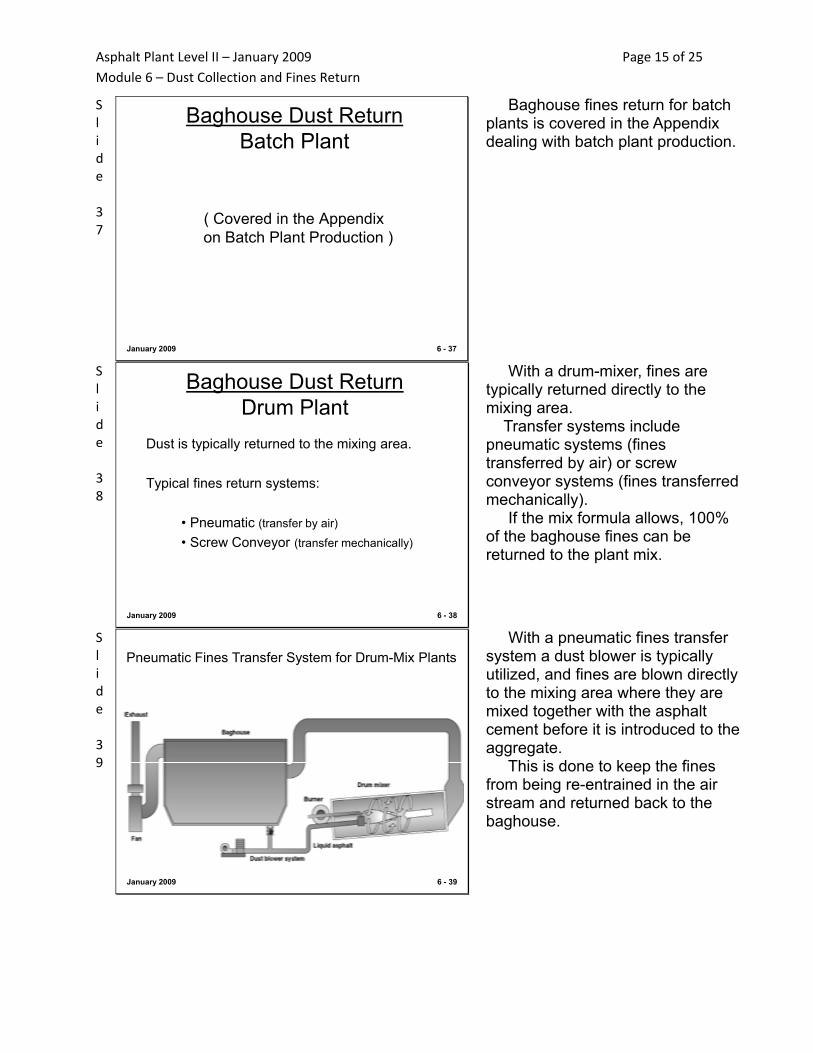
Slide 39
January 2009 6 - 39
Pneumatic Fines Transfer System for Drum-Mix Plants With a pneumatic fines transfer system a dust blower is typically utilized, and fines are blown directly to the mixing area where they are mixed together with the asphalt cement before it is introduced to the aggregate. This is done to keep the fines from being re-entrained in the air stream and returned back to the baghouse.

Asphalt Plant Level II – January 2009 Page 16 of 25 Module 6 – Dust Collection and Fines Return
Slide 40
January 2009 6 - 40
Pneumatic Fines Transfer System for Drum-Mix Plants This photograph shows a typical pneumatic fines return system on a drum-mix plant, where 100% of the baghouse fines can be re-used in the mix formula. The photo on the lower right is a close-up view of the pneumatic blower and airlock positioned below a baghouse. The airlock deposits the fines into the pneumatic transfer line, and the blower provides the transfer air to move the fines to the mixing area of the drum.
Slide 41
January 2009 6 - 41
This is an illustration of one style of mixing device where baghouse fines are reintroduced with the liquid asphalt. The fines are mixed with the asphalt cement to keep them from being re-circulated back to the baghouse, which keeps them from being re-introduced in the mix.
Slide 42
January 2009 6 - 42
Screw Conveyor Fines Return Systemfor Drum-Mix Plants
Screw conveyors can also be used to return fines to the mixing area on drum-mix plants. Screw conveyors are often selected because they involve less maintenance than pneumatic systems. Screw conveyors are typically used with counter-flow drum-mixers, as there is no significant air flow in the mixing area of a counter-flow drum, and screw conveyors are more predictable to maintain and easier to visibly check to make sure fines are being returned.

Asphalt Plant Level II – January 2009 Page 17 of 25 Module 6 – Dust Collection and Fines Return
Slide 43
January 2009 6 - 43
This is a photograph of a typical screw conveyor fines return system on a counter-flow drum-mix plant. Notice that the screw conveyor leading from the baghouse picks up the fines from the cyclone primary collector en-route to the mixing area of the drum.
Slide 44
January 2009 6 - 44
The fines from the baghouse and primary collector are then transferred to a fines “injection” screw that leads to the mixing area of the counter-flow drum-mixer.
Slide 45
January 2009 6 - 45
Partial Dust Return Drum Plant
Typical systems employed:
• (1) Variable speed airlock returning portion offines to drum-mixer and portion wasted
If all the baghouse fines can’t be used in the mix, several equipment options are available. The simplest system involves a variable speed airlock, which allows part of the fines to be re-introduced while the rest are wasted.

Asphalt Plant Level II – January 2009 Page 18 of 25 Module 6 – Dust Collection and Fines Return
Slide 46
January 2009 6 - 46
Partial Dust Return Drum Plant
This photograph shows a variable speed airlock installed in the screw conveyor between the baghouse and the drum. A part of the fines are re-introduced in the mix; the rest are being wasted/disposed of. Sometimes this dust is used as agricultural soil supplements. By monitoring final extracted gradations, a smaller amount or larger amount of fines can be directed to the mix by changing the speed of the airlock. The operator will establish a speed setting for the airlock for each production rate of each mix type. Fines that accumulate on the ground can be taken back to the quarry with a loader, or fines can be deposited directly into a truck. Some plants have “conditioning screws” or continuous pugmills at this reject area where water is mixed with the baghouse fines to reduce fugitive dust emissions.
Slide 47
January 2009 6 - 47
Partial Dust ReturnDrum Plant
Typical systems employed:
• (2) Transfer fines to silo and return only part of fines into drum-mixer with variable speed airlock (volumetric control)
Baghouse fines can also be transferred to a silo, where they can be used back in the mix. Here the baghouse fines product will be controlled in the system much like a cold feed bin product is controlled.
Asphalt Plant Level II – January 2009 Page 19 of 25 Module 6 – Dust Collection and Fines Return
Slide 48
January 2009 6 - 48
Partial Dust ReturnDrum Plant
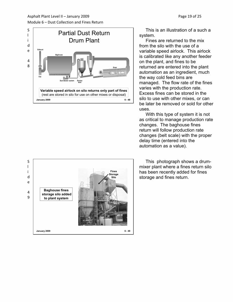
Variable speed airlock on silo returns only part of fines(rest are stored in silo for use on other mixes or disposal)
This is an illustration of a such a system. Fines are returned to the mix from the silo with the use of a variable speed airlock. This airlock is calibrated like any another feeder on the plant, and fines to be returned are entered into the plant automation as an ingredient, much the way cold feed bins are managed. The flow rate of the fines varies with the production rate. Excess fines can be stored in the silo to use with other mixes, or can be later be removed or sold for other uses. With this type of system it is not as critical to manage production rate changes. The baghouse fines return will follow production rate changes (belt scale) with the proper delay time (entered into the automation as a value).
Slide 49
January 2009 6 - 49
Baghouse finesstorage silo added
to plant system
FinesStorage
Silo
This photograph shows a drum-mixer plant where a fines return silo has been recently added for fines storage and fines return.

Asphalt Plant Level II – January 2009 Page 20 of 25 Module 6 – Dust Collection and Fines Return
Slide 50
January 2009 6 - 50
Output of Variable Speed Airlock
One issue of note, however, is the output of the fines airlock. Airlocks, by their very nature, are not linear devices. As they speed up, the output “flattens out.” This is because the pockets on the airlock have less of a chance to fill as the rotor speeds. It is very important that calibration charts are established for the baghouse fines airlock. The same issue exists when using airlocks on storage silos for mineral filler additive or lime additive.
Slide 51
January 2009 6 - 51
This is a typical calibration chart for a fines airlock. Notice how the output “flattens out” as speed increases. For accurate control of baghouse fines, mineral filler additive, and lime additive, it is important that the producer has a good handle on the output of this type device over different speed ranges. While this is not a department requirement, it is advisable that charts are maintained for airlock output and calibration. A simple chart like this, similar to a cold feed chart on a drum plant, is sufficient. If dust percentages in the mix fall out of tolerance range, this device should be checked for calibration accuracy. Most automated plants have a calibration procedure that automatically compensates for this output change.

Asphalt Plant Level II – January 2009 Page 21 of 25 Module 6 – Dust Collection and Fines Return
Slide 52
Airlocks are not linear, because of the way they operate.
Historically, this has notbeen a problem. But withvolumetric requirementsof new mixes, this is moreof an issue.
6 - 52January 2009
The reason airlock output “flattens out” is because the pockets on the airlock have less of a chance to fill as the speed increases. It is, therefore, very important that accurate calibration charts are established for the fines airlock. Historically, this has not been much of a problem. With new mixes where volumetric relationships are closely monitored, calibration and output of these devices should also be closely monitored.
Slide 53
January 2009 6 - 53
Partial Dust Return Drum Plant
Typical systems employed:
• (3) Transfer fines to silo and weigh desired fines back into drum-mixer
(eliminates control issues with volumetricfines return – amount of dust going backinto plant is absolutely known - weighed)
Another system that is growing in popularity for handling excess baghouse fines on a drum plant, is an equipment configuration where fines are transferred to a storage silo then weighed back into the mix as an additional ingredient through the use of a weigh pod on the dust silo.
Slide 54
January 2009 6 - 54
Partial Dust ReturnDrum Plant
“Reverse weigh pod” on silo weighs back fines desired(rest are stored in silo for use on other mixes or disposal)
This illustration shows such a system.

Asphalt Plant Level II – January 2009 Page 22 of 25 Module 6 – Dust Collection and Fines Return
Slide 55
January 2009
How a “reverse weighpod” is configured.
6 - 55
The key to weighing back the fines is the “reverse weigh pod” below the silo. This device works by charging a pod below the silo with fines, then watching the weight decrease in the pod while a variable speed airlock evacuates the pod. This eliminates the calibration concerns over airlock output, because fines are actually weighed back into the mix. The fines rate is tied to the aggregate flow of the drum plant, and is part of the mix formula in the plant automation, as previously discussed.
Slide 56
January 2009 6 - 56
“Reverse weigh pod”on storage silo
This photograph shows a reverse-weigh pod on a baghouse fines silo on a drum-mix plant.
Slide 57
January 2009 6 - 57
Adding Mineral Filler Drum-Mix Plant
Mineral filler is added in similarfashion to baghouse fines
(Lime for FC-5 mixes can addedwith the same type equipment)
When mineral filler is called for in the mix formula at a drum plant, the method for metering and measuring filler is essentially the same as metering back portions of the baghouse fines through a storage silo. A storage silo is typically installed on the plant for the mineral filler additive. A bulk silo can also be used for lime additive in FC-5 mixes. The lime injection system, however, must be configured so that the lime is added before the asphalt is injected.

Asphalt Plant Level II – January 2009 Page 23 of 25 Module 6 – Dust Collection and Fines Return
Slide 58
January 2009 6 - 58
Mineral Filler or Lime Silo Baghouse Fines Silo
This photograph shows an additional silo on the drum-mixer for mineral filler or lime additive. This plant has a reverse weigh pod on both silos, for both the baghouse fines and the mineral filler or lime additive. At this plant, the mineral filler / lime will be weighed back into the mix, and added to the screw conveyor taking fines from the baghouse and the cyclone to the mixing area. If this silo is being used for lime, the lime must be introduced to the aggregate before the asphalt cement is added.
Slide 59
January 2009 6 - 59
Best Management PracticesBaghouses
Key BMPs for fines return consistency (collection issues):
– Maintain effective cleaning mechanism– Manage cleaning for consistent pressure
drop across baghouse
Best Management Practices for baghouse operation from a collection issue standpoint focuses on these items: •Maintaining the cleaning mechanism to make sure the bags are cleaned properly. •Adjust the cleaning mechanism to make sure the pressure drop across the bags remains consistent.
Slide 60
January 2009 6 - 60
Best Management PracticesBaghouses
Key BMPs for fines return consistency (return issues):
– Maintain effective fines return system– Don’t make large production rate changes– Slowly ramp up/down production
Best Management Practices for baghouse operation from a fines return standpoint focuses on these items: •Inspect the fines return system regularly to make sure it is working. •Don’t make large production rate changes if you are returning 100% of the baghouse fines. It takes time for the fines to recycle through the collector. •Slowly ramp production rate changes up and down. By managing the elements on these two lists consistent mix can be produced.

Asphalt Plant Level II – January 2009 Page 24 of 25 Module 6 – Dust Collection and Fines Return
Slide 61
January 2009 6 - 61
Best Management PracticesBaghouses
If you have a problem with –200 or voidscheck the baghouse
If your test results show a problem with the –200 level or the voids are out of tolerance, it is advisable to start your trouble-shooting by inspecting the baghouse and fines return system for proper operation.
Slide 62
January 2009 6 - 62
InspectionDust Control Equipment
• There are no Department requirements for dust control equipment.
• Dust return in the mix is governed by mix acceptance criteria.
• Dust collection and return is critical, however, because it directly affects volumetric properties of the mix
As stated earlier in this module, there are no Department requirements or specifications governing dust control equipment. Mix formulas and gradations are closely monitored, however, as covered in Module 10. The dust collection and dust return equipment can have a significant impact on mix performance. Baghouse dust directly affects volumetric properties of the mix. So even though specific requirements are not listed for air pollution control equipment, it is advisable that the contractor and the Engineer watch the operational efficiencies of this equipment.

Asphalt Plant Level II – January 2009 Page 25 of 25 Module 6 – Dust Collection and Fines Return
Slide 63
January 2009 6 - 63
Module 6What we covered….
• Types of emission/dust control systems• Difference between primary and secondary
collection/collectors• Re-introducing collected dust in the mix• Best Management Practices for consistent
dust return• How dust collection equipment can impact
volumetric properties of the mix
Slide 64
January 2009 6 - 64
QUESTIONS ?
Any Questions?