asl letter report 288-20-087.2501 permeability testing
TRANSCRIPT
Reference: 244-20-087.2501
Date: 11th February 2021
T h e G e o - E n v i r o n m e n t a l S e r v i c e P r o v i d e r
ASL, Holly Farm Business Park, Honiley, Warwickshire, CV8 1NP t: +44 (0)1926 485 508 f: +44 (0)1926 485 507 e: [email protected] w: www.aslenvironmental.co.uk
ASPECTS SERVICES (UK) L IMITED, COMPANY REGISTRATION NUMBER 5489459
REGISTERED OFFICE: HIGHDOWN HOUSE, 11 HIGHDOWN ROAD, SYDENHAM, LEAMIGTON SPA, CV31 1XT
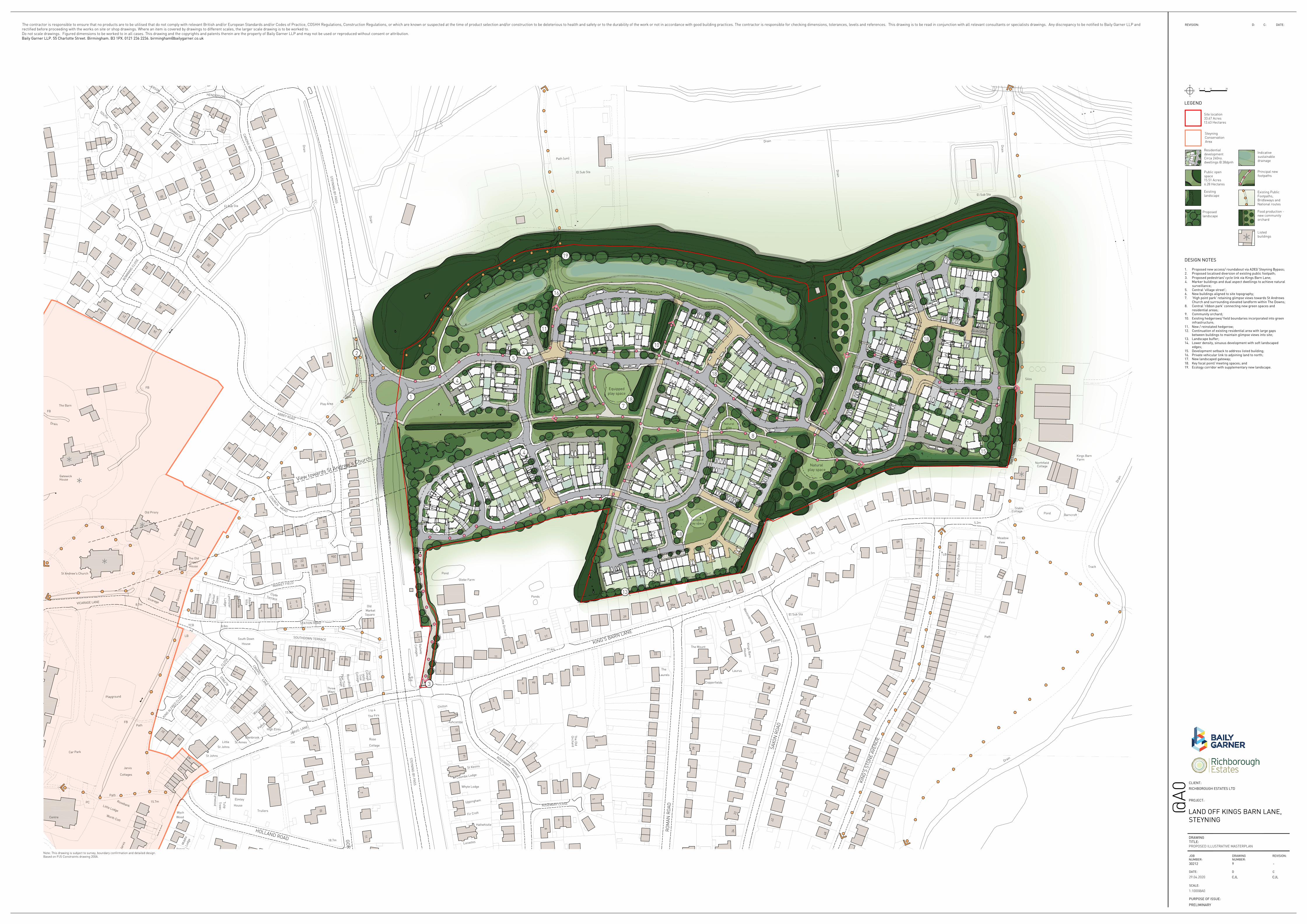
Richborough Estates 2nd Floor Waterloo House 20 Waterloo Street Birmingham B2 5TB For the attention of: Mr Dean Knight PERMEABILITY TESTING LAND OFF KING’S BARN LANE, STEYNING, WEST SUSSEX Dear Dean, 1.0 INTRODUCTION In January 2021, ASL was instructed by Richborough Estates to undertake permeability testing at the site known as Land off King’s Barn Lane, Steyning, West Sussex. The scope of works for this project was set out in ASL’s proposal reference 288-20-087.elo.3542, dated 14th January 2021. This letter report presents the factual results of the permeability testing completed at the site together with interpretative comment on the infiltration rates and ground conditions encountered. It is understood that the proposed development comprises the construction of approximately 240 residential dwellings with associated areas of hardstanding for access and parking and soft landscaping for gardens together with areas of public open space including sustainable drainage features. A Proposed Illustrative Masterplan is presented in Appendix I. The proposed drainage features are located across the north of the site as attenuation ponds with a further soakaway feature proposed centrally in the west. 2.0 THE SITE The site is located to the north and west of King’s Barn Lane, to the east of Steyning Bypass, to the south of an unnamed roadway and to the north-east of the village of Steyning. The site can be located approximately by National Grid Reference TQ184115 as presented as Figure 1. The site comprises an irregularly shaped piece of land with maximum dimensions of approximately 570m by 330m and the long axis aligned approximately east to west. The site topography varies across the site. The high point of the site is in the south-west formed by a small rise surrounded by downward slopes with the steepest slopes extending to the north-western boundary from this point. The remainder of the site is undulating with various changes in elevation and sloping ground including a hollow located centrally in the east of the site that may be the low point of the site. The site boundary is locally not physically marked in the south-west with this area open to further agricultural land used for grazing horses. The remainder of the south-western boundary is generally marked by wooden post and wire mesh fencing. The south-eastern boundary is marked by various wooden fencing and locally hedgerows associated with residential dwellings to the south.
T h e G e o - E n v i r o n m e n t a l S e r v i c e P r o v i d e r
ASL Ref 288-20-087.2501 Page 2 of 4
The site is bound to the west by Steyning Bypass and residential dwellings, to the north by undeveloped open space, electrical substations centrally and in the north-east and a sewage pumping station, to the east by King’s Barn Lane with agricultural land and a farm beyond, to the south and south-east by residential dwellings and to the south-west by Glebe Farm. The sewage pumping station comprises a two storey brick walled and sloping tiled roofed structure. This structure has an overhead power supply from the electrical substation to the north-east. A shipping container is located in the south-east corner of the pumping station compound that appears to be a backup generator. At the time of the intrusive works portions of the site, particularly existing access points and routes, were noted to be very wet and soft, with areas of standing water also locally present across the site. 3.0 GEOLOGY The British Geological Survey (BGS) Sheets No. 318 and 333 – Brighton and Worthing (Solid and Drift) and the Geology of Britain Viewer indicates the east and locally the central portion of the site to be directly underlain by drift deposits of the 2nd River Terrace Deposits. The 2nd River Terrace Deposits are generally described as ‘Sand and gravel, flint, chalk and sandstone, with silt and clay’ by the BGS. The thickness of the 2nd River Terrace Deposits is not defined by the BGS in the vicinity of the site, but this stratum is expected to be of limited thickness. From here on the 2nd River Terrace Deposits will be referred to as River Terrace Deposits. The majority of the central portion of the site is indicated to be directly underlain by drift deposits comprising Head. The Head deposits are generally described as ‘variable deposits of sandy, silty clay, locally gravelly; chalky and flinty in dry chalk valleys’ by the BGS. The thickness of the Head is not defined by the BGS in the vicinity of the site, but this stratum is expected to be of limited thickness. The remainder of the site in the west is indicated to be devoid of drift deposits. Solid geology comprising the Upper Greensand Formation is indicated to locally subcrop beneath the River Terrace Deposits located centrally and outcrop at the surface in the south-west. The Upper Greensand Formation is generally described as ‘Siltstone to very fine grained sandstone, bioturbated, pale greenish yellow mottled grey’ by the BGS. The thickness of the Upper Greensand Formation is indicated to be up to 36m thick by the BGS in the vicinity of the site. The remaining drift deposits, the Upper Greensand Formation and the remainder of the site in the west are indicated to be underlain by solid geology comprising the Gault Formation. The Gault Formation is generally described as ‘Mudstone, stiff, shelly, glauconitic, micaceous and with seams of phosphatic nodule in part. Yellow when weathered becomes dark blueish grey with depth’ by the BGS. The thickness of the Gault Formation is indicated to be between 65m and 105m thick by the BGS in the vicinity of the site. Further drift deposits comprising Alluvium are indicated to be present at the surface directly to the north and north-west of the site and may locally encroach onto the site. The Alluvium is generally described as ‘Normally soft to firm consolidated, compressible silty clay, but can contain layers of silt, sand, peat and basal gravel. A stronger, desiccated surface zone may be present’ by the BGS. The thickness of the Alluvium is not defined by the BGS in the vicinity of the site. Further solid geology comprising the West Melbury Marly Chalk Formation is indicated to be present overlying the Upper Greensand Formation to the south of the site and may locally encroach onto site. The West Melbury Marly Chalk Formation is generally described as ‘Chalk, marly with fossiliferous limestone, pale grey. Glauconitic Marl Member at base’ by the BGS. The thickness of the West Melbury Marly Chalk Formation is indicated to be between 30m to 35m thick
T h e G e o - E n v i r o n m e n t a l S e r v i c e P r o v i d e r
ASL Ref 288-20-087.2501 Page 3 of 4
by the BGS in the vicinity of the site. However, if present at the site, this stratum is anticipated to be of limited thickness. In addition to the published geology, it is expected that Topsoil will be present at the surface given the current use of the site. Made Ground is also anticipated in the vicinity of existing structures and services. Made Ground materials may also be present in the north-west of Area 5 where reprofiling works and/or excavation works appear to have been completed. 4.0 GROUND INVESTIGATION AND TESTING It was initially proposed to completed soakaway testing within trial pit excavations at the site. However, due to the very wet and soft nature of the ground surface across the site at the time of these fieldworks, it was considered that significant difficulties would be experienced with trafficking heavy plant across the site. The scope of works was therefore redefined to comprise ten windowless sampler boreholes. The boreholes were all installed with monitoring standpipes to allow the subsequent completion of falling head permeability tests. The intrusive investigation was designed to target the location of the proposed drainage features at the site. The positions of exploratory holes have been surveyed and plotted approximately on Figure 2. The ground investigation was carried out in general accordance with BS5930 (2015) ‘Code of Practice for Site Investigations’ and BS10175+A2:2017 ‘Code of Practice for the Investigation of Potentially Contaminated Sites’ and in accordance with current best practice. The ground investigation was carried out between 18th and 21st January 2021. The intrusive investigation was supervised by a suitably experienced geo-environmental engineer from ASL. The exploratory holes were logged by the supervising engineer and the logs are presented in Appendix II Falling head permeability tests were completed within the monitoring standpipes installed within all of the boreholes undertaken at the site. The falling head permeability tests were completed by filling the installations with clean water and monitoring the rate at which the water fell. The results of the falling head permeability tests are presented in Appendix II. 5.0 GROUND CONDITIONS The intrusive investigation generally encountered a limited thickness of Topsoil and Made Ground (Topsoil) typically overlying cohesive materials considered to represent solid geology of the Gault Formation. The Gault Formation materials were typically found to comprise stiff to very stiff light brown and grey brown, locally slightly sandy CLAY. Cohesive materials considered to represent possible Head was encountered at WS102, WS103 and WS110, located centrally in the north of the site, with these materials present to depths between 1.4m and 3.45. Where proven the Head materials were underlain by cohesive materials of the Gault Formation. Groundwater was not encountered within any of the exploratory boreholes during their formation. Full details of the ground conditions encountered are presented on the borehole logs included in Appendix II. The locations of the exploratory holes are presented on Figure 2.
T h e G e o - E n v i r o n m e n t a l S e r v i c e P r o v i d e r
ASL Ref 288-20-087.2501 Page 4 of 4
6.0 SOAKAGE POTENTIAL As part of the investigation falling head permeability test were completed within the monitoring standpipes installed at all of the boreholes undertaken as part of this investigation. The locations of the boreholes were selected to target the location of proposed drainage features at the proposed development. Positive infiltration was not recorded for the falling head permeability tests undertaken at WS101A, WS101B, WS105, WS106 and WS109. The results of the falling head permeability tests undertaken at the remaining borehole installations recorded positive infiltration rates of between 3.12x10⁻¹⁰m/s and 2.95x10⁻⁸m/s at WS104 and WS110, respectively. Based on the results of the falling head permeability tests and the cohesive nature of the underlying ground conditions, it is considered that the use of shallow soakaways or other infiltration drainage systems is unlikely to be feasible for the site. It is recommended that the advice of a specialist drainage engineer is sought with regards to the design and installation of any drainage systems which may form part of the proposed development. Yours sincerely for ASL
STEVE JONES Associate Director M: 07525 905 803 E: [email protected] W: www.aslenvironmental.co.uk Encl. Figures Appendix I Illustrative Masterplan Appendix II Field Records
FIGURES
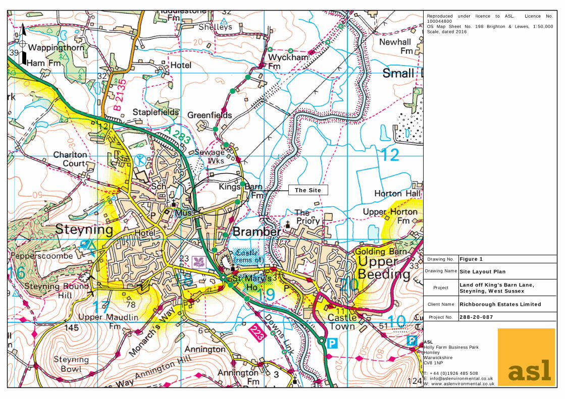
The Site
Reproduced under licence to ASL. Licence No.100044800OS Map Sheet No. 198 Brighton & Lewes, 1:50,000Scale, dated 2016
Drawing Name
Project
Client Name
Project No.
Drawing No.
Richborough Estates Limited
Land off King’s Barn Lane, Steyning, West Sussex
Site Layout Plan
288-20-087
Figure 1
ASLHolly Farm Business ParkHonileyWarwickshireCV8 1NP
T: +44 (0)1926 485 508E: [email protected]: www.aslenvironmental.co.uk
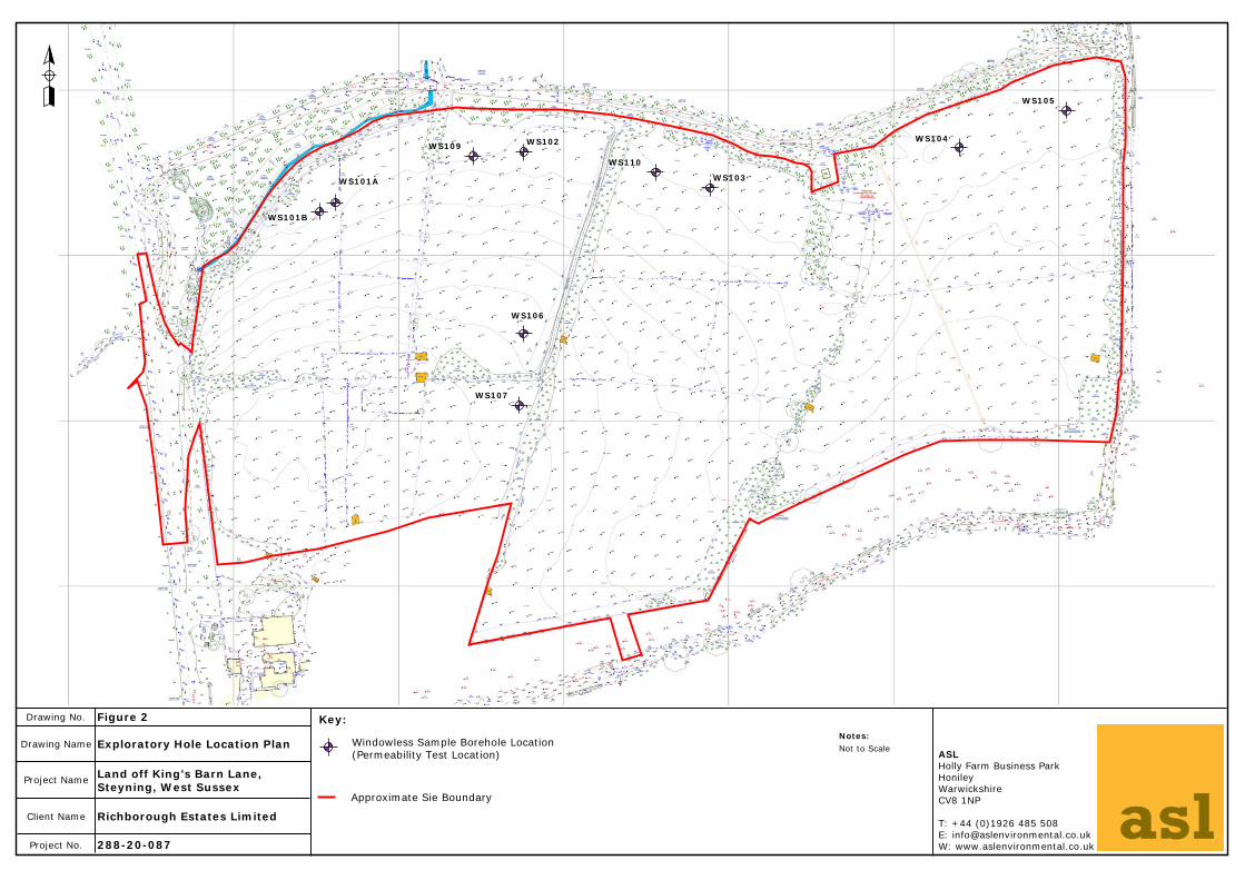
WS101A
WS102
WS103
WS104
WS105
WS106
WS107
WS109
WS110
WS101B
Drawing Name
Project Name
Client Name
Project No.
Drawing No.
Exploratory Hole Location PlanASLHolly Farm Business ParkHonileyWarwickshireCV8 1NP
T: +44 (0)1926 485 508E: [email protected]: www.aslenvironmental.co.uk
Richborough Estates Limited
Land off King’s Barn Lane, Steyning, West Sussex
288-20-087
Notes:Not to Scale
Approximate Sie Boundary
Windowless Sample Borehole Location(Permeability Test Location)
Figure 2 Key:
APPENDIX I
ILLUSTRATIVE MASTERPLAN
6.5m
RO
MAN
RO
AD
47a
47
Meadow
Drai
n
SAXO
N R
OAD
5
Laurus
Pond
6
Stable
5
KIN
G'S
2
Drain
Uppingham
Pear Tree
Foxton
25
Playground
2
Silvermead
STATION ROAD
1
22
CLOSE
1
55
20
6
Old
1
Path (um)
Play Area
Cottages
Mid
dle
Trees
St Johns
6
BOW
MAN
S CL
OSE
24
The Old
Lodge
Villa
Lyminster
65
49
48
11a
49
13
13
8
2
Northfield
9
BAR
N
St Kevins
Haltwhistle
22
Cottage
Tree
The Old
3
Roundhill
1 to 4
8.8m
Clyde
CRIPPS
Terrace
GO
RIN
G R
OAD
TCB
7
16
233
KING A
LFRED C
LOSE
LB
5
HOLLAND ROAD
1WALK
Wych Trullers
El Sub Sta
17
HENDERSON
28
VICARAGE LANE
The Barn
Mar
ket
Dow
n
22
Westonbrook
5.2m
Laurels
47
Drain
41
Little Orchard
11
19
2.9m
6.5m
7
8
2
Holly
Pond
LANE
House
MARKET FIELD 7
1
St Annes
8
Little
WoodCentre
6
6
6
Lodg
e
1
27
20
40
Kings BarnFarm
12
51
7
25
11
1
5
SOUTHDOWN TERRACE
7
1
Ways
The Mount
35a
17
11
El
Silos
1
Padua
9
19
KIN
G
35
2
18 14
5
SM
2
Little Lodge
HENDERSON
110
14
Worth Cott
7
16
Annen
4
WALK
18
House
Elmley
11
38
Mon
ks W
alk
25
Drain
House
13
FB
Braeside
19
27
14
Kings B
arn
4a
Copperfields
1
6
10
15
12
The Firs
11
Ling13.3m
Lucastes
Three
Ashcombe
19
Railw
ay
1
Orchard
6a
Gos
mar
k
6
1
Rosemary
3
4
LB
Pump House
20
Warren End
8
12
15
31
Tulip
Glenbrook
CANON
S WAY
SOUTH
20
23 11
24
House
Coach
CHURCH
2
30
House
4
2
9
14
Barncroft
Cottage
10
9
Sta
Whyte Lodge
AVENUE
11.4m
1
26
2
1
6
15
El Sub Sta
23
7
4
3
1
El Sub Sta
Path
10
20a
21
10
33
Lynwood
1
27
22
9
32
Old Priory
36
Path
Ble
ncoe
31
Gatewick
7
MEAD15
75
26
LB
KIN
G'S
STO
NE
AVEN
UE
Path
4
14
39
13
18
LANE
Cottages
Chilton
29
ROSEMARY
37a
El Sub Sta
Sub
1
Spring
1
Rose
Ponds
1
17
Drain
Drain
FB
12
15
24
10
1
MarketSquare
Rosebank
Jarvis
Jarv
is
2
9
ASH
8
Vicarage
St Andrew's Church
21
PC
1
28
FBABBEY ROAD
24
Kin
g's
Bar
n En
d
22
44
The
View
40
11
37
3
38
39a
Cottage
Track
Coombe Lodge
High Elms
ROSEMARY CLOSE
LANE
KING'S BARN LANE
12
JARVIS
10
8
Fir Croft
Cottage
14
Cottage
7
Cottage
7
2
ALFR
ED
13
5
Track
6
Drain
Drain
18.7m
Glebe Farm
Drain
South Down
STEYNIN
G-B
Y-PASS
10
43a
22
MIMMACK
24
7
15.7m
14
27
St Johns
CL
Car Park
8.7m
26
Albany
1518
12
STEYNIN
G-B
Y-PASS
0 105 25
N
S
W E
ResidentialdevelopmentCirca 240no.dwellings @ 38dpnh
Public openspace15.51 Acres6.28 Hectares
Existinglandscape
Proposedlandscape
Indicativesustainabledrainage
Principal newfootpaths
Listedbuildings*
Site location33.67 Acres13.63 Hectares
DESIGN NOTES
1. Proposed new access/ roundabout via A283/ Steyning Bypass;
2. Proposed localised diversion of existing public footpath;
3. Proposed pedestrian/ cycle link via Kings Barn Lane;
4. Marker buildings and dual aspect dwellings to achieve natural
surveillance;
5. Central 'village street';
6. New buildings aligned to site topography;
7. 'High point park' retaining glimpse views towards St Andrews
Church and surrounding elevated landform within The Downs;
8. Central 'ribbon park' connecting new green spaces and
residential areas;
9. Community orchard;
10. Existing hedgerows/ field boundaries incorporated into green
infrastructure;
11. New / reinstated hedgerow;
12. Continuation of existing residential area with large gaps
between buildings to maintain glimpse views into site;
13. Landscape buffer;
14. Lower density, sinuous development with soft landscaped
edges;
15. Development setback to address listed building;
16. Private vehicular link to adjoining land to north;
17. New landscaped gateway;
18. Key focal point/ meeting spaces; and
19. Ecology corridor with supplementary new landscape.
Naturalplay space
LEGEND
Note: This drawing is subject to survey, boundary confirmation and detailed design.Based on PJS Constraints drawing 200A.
CLIENT:
PROJECT:
PURPOSE OF ISSUE:
DRAWINGTITLE:
@A0
RICHBOROUGH ESTATES LTD
LAND OFF KINGS BARN LANE,STEYNING
PRELIMINARY
30212
JOBNUMBER:
DRAWINGNUMBER:
PROPOSED ILLUSTRATIVE MASTERPLAN
CJL
D C
CJL
DATE:
29.04.2020
9 -
REVISION:
REVISION: D: C: DATE:The contractor is responsible to ensure that no products are to be utilised that do not comply with relevant British and/or European Standards and/or Codes of Practice, COSHH Regulations, Construction Regulations, or which are known or suspected at the time of product selection and/or construction to be deleterious to health and safety or to the durability of the work or not in accordance with good building practices. The contractor is responsible for checking dimensions, tolerances, levels and references. This drawing is to be read in conjunction with all relevant consultants or specialists drawings. Any discrepancy to be notified to Baily Garner LLP andrectified before proceeding with the works on site or shop drawings. Where an item is covered by drawings to different scales, the larger scale drawing is to be worked to.Do not scale drawings. Figured dimensions to be worked to in all cases. This drawing and the copyrights and patents therein are the property of Baily Garner LLP and may not be used or reproduced without consent or attribution.Baily Garner LLP. 55 Charlotte Street. Birmingham. B3 1PX. 0121 236 2236. [email protected]
SCALE:
1:1000@A0
SteyningConservationArea
Existing PublicFootpaths,Bridleways andNational routes
*
*
*
** *
Naturalplay
Equippedplay space
1
2
3
4
5
6
7
8
9
10
10
11
12
13
1314
15
16
19
17
18
18
Equippedplay space
Food production -new communityorchard
View towards St Andrew's Church
18
184
4
4
4
4
4
APPENDIX II
FIELD RECORDS
Sample and In Situ Testing
Depth (m) Type SPT HPV (KPa)
PID (ppm)
Depth(m)
0.40
1.50
2.40
3.45
Level(m) Stratum Description
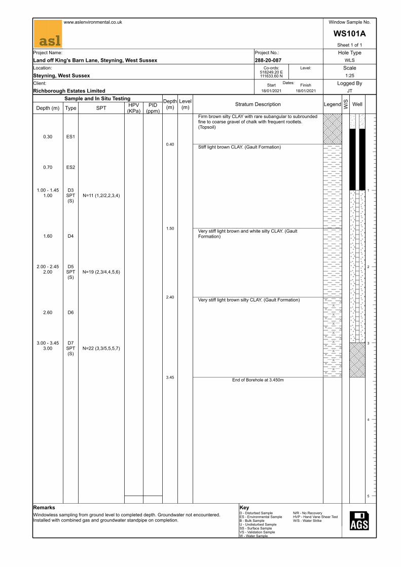
Firm brown silty CLAY with rare subangular to subrounded fine to coarse gravel of chalk with frequent rootlets. (Topsoil)
Stiff light brown CLAY. (Gault Formation)
Very stiff light brown and white silty CLAY. (Gault Formation)
Very stiff light brown silty CLAY. (Gault Formation)
End of Borehole at 3.450m
Legend W/S Well
1
2
3
4
5
0.30 ES1
0.70 ES2
1.00 - 1.45 D31.00 SPT
(S)N=11 (1,2/2,2,3,4)
1.60 D4
2.00 - 2.45 D52.00 SPT
(S)N=19 (2,3/4,4,5,6)
2.60 D6
3.00 - 3.45 D73.00 SPT
(S)N=22 (3,3/5,5,5,7)
www.aslenvironmental.co.uk Window Sample No.
WS101ASheet 1 of 1
Project Name: Project No.: Hole TypeLand off King's Barn Lane, Steyning, West Sussex 288-20-087 WLSLocation: Co-ords: Level: ScaleSteyning, West Sussex
518249.20 E 111633.60 N 1:25
Client: Dates:Start Finish Logged ByRichborough Estates Limited 18/01/2021 18/01/2021 JT
RemarksWindowless sampling from ground level to completed depth. Groundwater not encountered. Installed with combined gas and groundwater standpipe on completion.
KeyD - Disturbed Sample N/R - No RecoveryES - Environmental Sample HVP - Hand Vane Shear TestB - Bulk Sample W/S - Water StrikeU - Undisturbed SampleSS - Surface SampleVS - Validation SampleW - Water Sample
Sample and In Situ Testing
Depth (m) Type SPT HPV (KPa)
PID (ppm)
Depth(m)
0.40
1.20
2.50
3.00
Level(m) Stratum Description
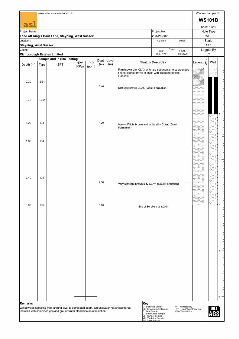
Firm brown silty CLAY with rare subangular to subrounded fine to coarse gravel of chalk with frequent rootlets. (Topsoil)
Stiff light brown CLAY. (Gault Formation)
Very stiff light brown and white silty CLAY. (Gault Formation)
Very stiff light brown silty CLAY. (Gault Formation)
End of Borehole at 3.000m
Legend W/S Well
1
2
3
4
5
0.30 ES1
0.70 ES2
1.20 D3
1.60 D4
2.40 D5
3.00 D6
www.aslenvironmental.co.uk Window Sample No.
WS101BSheet 1 of 1
Project Name: Project No.: Hole TypeLand off King's Barn Lane, Steyning, West Sussex 288-20-087 WLSLocation: Co-ords: Level: ScaleSteyning, West Sussex 1:25Client: Dates:Start Finish Logged ByRichborough Estates Limited 18/01/2021 18/01/2021 JT
RemarksWindowless sampling from ground level to completed depth. Groundwater not encountered. Installed with combined gas and groundwater standpipe on completion.
KeyD - Disturbed Sample N/R - No RecoveryES - Environmental Sample HVP - Hand Vane Shear TestB - Bulk Sample W/S - Water StrikeU - Undisturbed SampleSS - Surface SampleVS - Validation SampleW - Water Sample
Sample and In Situ Testing
Depth (m) Type SPT HPV (KPa)
PID (ppm)
Depth(m)
0.40
1.40
3.45
Level(m) Stratum Description
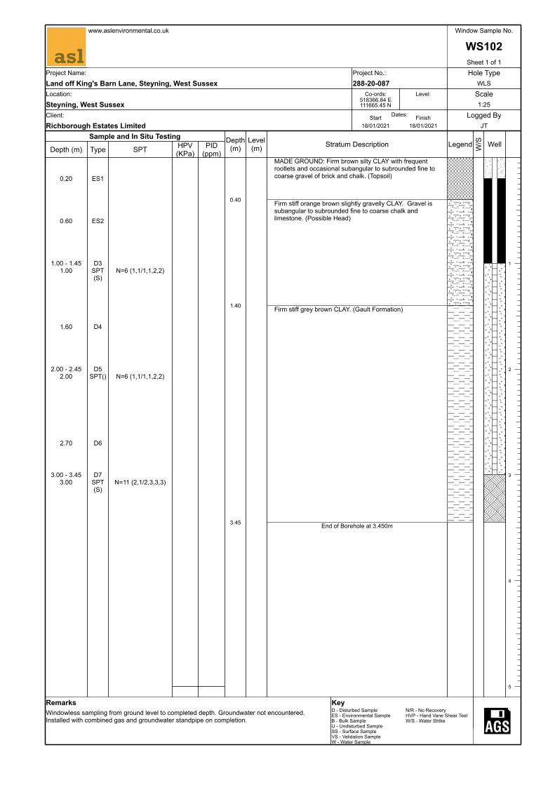
MADE GROUND: Firm brown silty CLAY with frequent rootlets and occasional subangular to subrounded fine to coarse gravel of brick and chalk. (Topsoil)
Firm stiff orange brown slightly gravelly CLAY. Gravel is subangular to subrounded fine to coarse chalk and limestone. (Possible Head)
Firm stiff grey brown CLAY. (Gault Formation)
End of Borehole at 3.450m
Legend W/S Well
1
2
3
4
5
0.20 ES1
0.60 ES2
1.00 - 1.45 D31.00 SPT
(S)N=6 (1,1/1,1,2,2)
1.60 D4
2.00 - 2.45 D52.00 SPT() N=6 (1,1/1,1,2,2)
2.70 D6
3.00 - 3.45 D73.00 SPT
(S)N=11 (2,1/2,3,3,3)
www.aslenvironmental.co.uk Window Sample No.
WS102Sheet 1 of 1
Project Name: Project No.: Hole TypeLand off King's Barn Lane, Steyning, West Sussex 288-20-087 WLSLocation: Co-ords: Level: ScaleSteyning, West Sussex
518366.84 E 111665.45 N 1:25
Client: Dates:Start Finish Logged ByRichborough Estates Limited 18/01/2021 18/01/2021 JT
RemarksWindowless sampling from ground level to completed depth. Groundwater not encountered. Installed with combined gas and groundwater standpipe on completion.
KeyD - Disturbed Sample N/R - No RecoveryES - Environmental Sample HVP - Hand Vane Shear TestB - Bulk Sample W/S - Water StrikeU - Undisturbed SampleSS - Surface SampleVS - Validation SampleW - Water Sample
Sample and In Situ Testing
Depth (m) Type SPT HPV (KPa)
PID (ppm)
Depth(m)
0.40
1.00
2.10
3.45
Level(m) Stratum Description
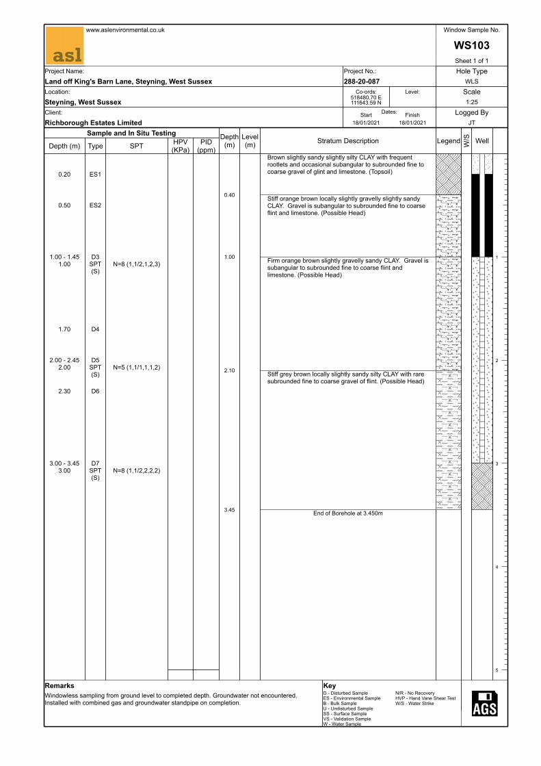
Brown slightly sandy slightly silty CLAY with frequent rootlets and occasional subangular to subrounded fine to coarse gravel of glint and limestone. (Topsoil)
Stiff orange brown locally slightly gravelly slightly sandy CLAY. Gravel is subangular to subrounded fine to coarse flint and limestone. (Possible Head)
Firm orange brown slightly gravelly sandy CLAY. Gravel is subangular to subrounded fine to coarse flint and limestone. (Possible Head)
Stiff grey brown locally slightly sandy silty CLAY with rare subrounded fine to coarse gravel of flint. (Possible Head)
End of Borehole at 3.450m
Legend W/S Well
1
2
3
4
5
0.20 ES1
0.50 ES2
1.00 - 1.45 D31.00 SPT
(S)N=8 (1,1/2,1,2,3)
1.70 D4
2.00 - 2.45 D52.00 SPT
(S)N=5 (1,1/1,1,1,2)
2.30 D6
3.00 - 3.45 D73.00 SPT
(S)N=8 (1,1/2,2,2,2)
www.aslenvironmental.co.uk Window Sample No.
WS103Sheet 1 of 1
Project Name: Project No.: Hole TypeLand off King's Barn Lane, Steyning, West Sussex 288-20-087 WLSLocation: Co-ords: Level: ScaleSteyning, West Sussex
518480.70 E 111643.59 N 1:25
Client: Dates:Start Finish Logged ByRichborough Estates Limited 18/01/2021 18/01/2021 JT
RemarksWindowless sampling from ground level to completed depth. Groundwater not encountered. Installed with combined gas and groundwater standpipe on completion.
KeyD - Disturbed Sample N/R - No RecoveryES - Environmental Sample HVP - Hand Vane Shear TestB - Bulk Sample W/S - Water StrikeU - Undisturbed SampleSS - Surface SampleVS - Validation SampleW - Water Sample
Sample and In Situ Testing
Depth (m) Type SPT HPV (KPa)
PID (ppm)
Depth(m)
1.00
3.00
Level(m) Stratum Description
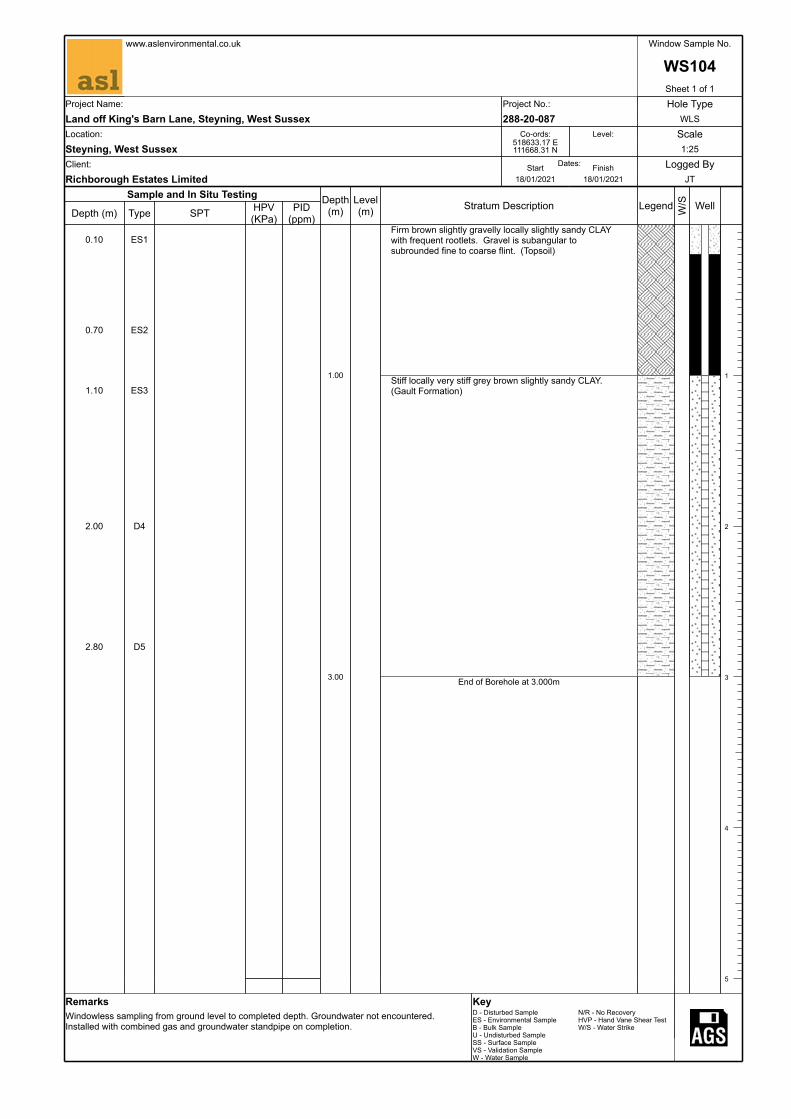
Firm brown slightly gravelly locally slightly sandy CLAY with frequent rootlets. Gravel is subangular to subrounded fine to coarse flint. (Topsoil)
Stiff locally very stiff grey brown slightly sandy CLAY. (Gault Formation)
End of Borehole at 3.000m
Legend W/S Well
1
2
3
4
5
0.10 ES1
0.70 ES2
1.10 ES3
2.00 D4
2.80 D5
www.aslenvironmental.co.uk Window Sample No.
WS104Sheet 1 of 1
Project Name: Project No.: Hole TypeLand off King's Barn Lane, Steyning, West Sussex 288-20-087 WLSLocation: Co-ords: Level: ScaleSteyning, West Sussex
518633.17 E 111668.31 N 1:25
Client: Dates:Start Finish Logged ByRichborough Estates Limited 18/01/2021 18/01/2021 JT
RemarksWindowless sampling from ground level to completed depth. Groundwater not encountered. Installed with combined gas and groundwater standpipe on completion.
KeyD - Disturbed Sample N/R - No RecoveryES - Environmental Sample HVP - Hand Vane Shear TestB - Bulk Sample W/S - Water StrikeU - Undisturbed SampleSS - Surface SampleVS - Validation SampleW - Water Sample

Sample and In Situ Testing
Depth (m) Type SPT HPV (KPa)
PID (ppm)
Depth(m)
0.45
3.45
Level(m) Stratum Description
Firm brown slightly sandy CLAY with frequent rootlets and rare subangular to subrounded fine to coarse gravel oF limestone and flint. (Topsoil)
Stiff to very stiff light brown and grey becoming grey brown with depth locally slightly sandy CLAY. (Gault Formation)
End of Borehole at 3.450m
Legend W/S Well
1
2
3
4
5
0.30 ES1
0.70 ES2
1.00 - 1.45 D31.00 SPT
(S)N=7 (1,1/1,2,2,2)
1.70 D4
2.00 - 2.45 D52.00 SPT
(S)N=10 (1,2/2,2,3,3)
2.70 D6
3.00 - 3.45 D83.00 SPT
(S)N=7 (1,1/1,2,2,2)
www.aslenvironmental.co.uk Window Sample No.
WS105Sheet 1 of 1
Project Name: Project No.: Hole TypeLand off King's Barn Lane, Steyning, West Sussex 288-20-087 WLSLocation: Co-ords: Level: ScaleSteyning, West Sussex
518698.57 E 111690.90 N 1:25
Client: Dates:Start Finish Logged ByRichborough Estates Limited 18/01/2021 18/01/2021 JT
RemarksWindowless sampling from ground level to completed depth. Groundwater not encountered. Installed with combined gas and groundwater standpipe on completion.
KeyD - Disturbed Sample N/R - No RecoveryES - Environmental Sample HVP - Hand Vane Shear TestB - Bulk Sample W/S - Water StrikeU - Undisturbed SampleSS - Surface SampleVS - Validation SampleW - Water Sample

Sample and In Situ Testing
Depth (m) Type SPT HPV (KPa)
PID (ppm)
Depth(m)
0.35
1.00
2.50
3.45
Level(m) Stratum Description
MADE GROUND: Firm brown slightly gravelly silty CLAY with frequent rootlets. Gravel is subangular to subrounded fine to coarse brick, charcoal and sandstone. (Topsoil)
Firm to stiff lightly brown and grey brown locally slightly sandy silty CLAY. (Gault Formation)
Stiff grey brown slightly gravelly silty CLAY. Gravel is subangular fine to coarse mudstone lithorelicts. (Gault Formation)
Very stiff grey gravelly silty CLAY. Gravel is subangular fine to coarse mudstone lithorelicts. (Gault Formation)
Locally very weak mudstone.
End of Borehole at 3.450m
Legend W/S Well
1
2
3
4
5
0.20 ES1
0.50 ES2
1.00 - 1.45 D31.00 SPT
(S)N=16 (3,3/4,4,4,4)
1.50 D4
2.00 - 2.45 D52.00 SPT
(S)N=14 (3,2/3,3,4,4)
2.60 D6
3.00 - 3.45 D73.00 SPT
(S)N=12 (2,2/2,3,3,4)
www.aslenvironmental.co.uk Window Sample No.
WS106Sheet 1 of 1
Project Name: Project No.: Hole TypeLand off King's Barn Lane, Steyning, West Sussex 288-20-087 WLSLocation: Co-ords: Level: ScaleSteyning, West Sussex
518366.90 E 111554.57 N 1:25
Client: Dates:Start Finish Logged ByRichborough Estates Limited 18/01/2021 18/01/2021 JT
RemarksWindowless sampling from ground level to completed depth. Groundwater not encountered. Installed with combined gas and groundwater standpipe on completion.
KeyD - Disturbed Sample N/R - No RecoveryES - Environmental Sample HVP - Hand Vane Shear TestB - Bulk Sample W/S - Water StrikeU - Undisturbed SampleSS - Surface SampleVS - Validation SampleW - Water Sample
Sample and In Situ Testing
Depth (m) Type SPT HPV (KPa)
PID (ppm)
Depth(m)
0.40
0.90
3.45
Level(m) Stratum Description
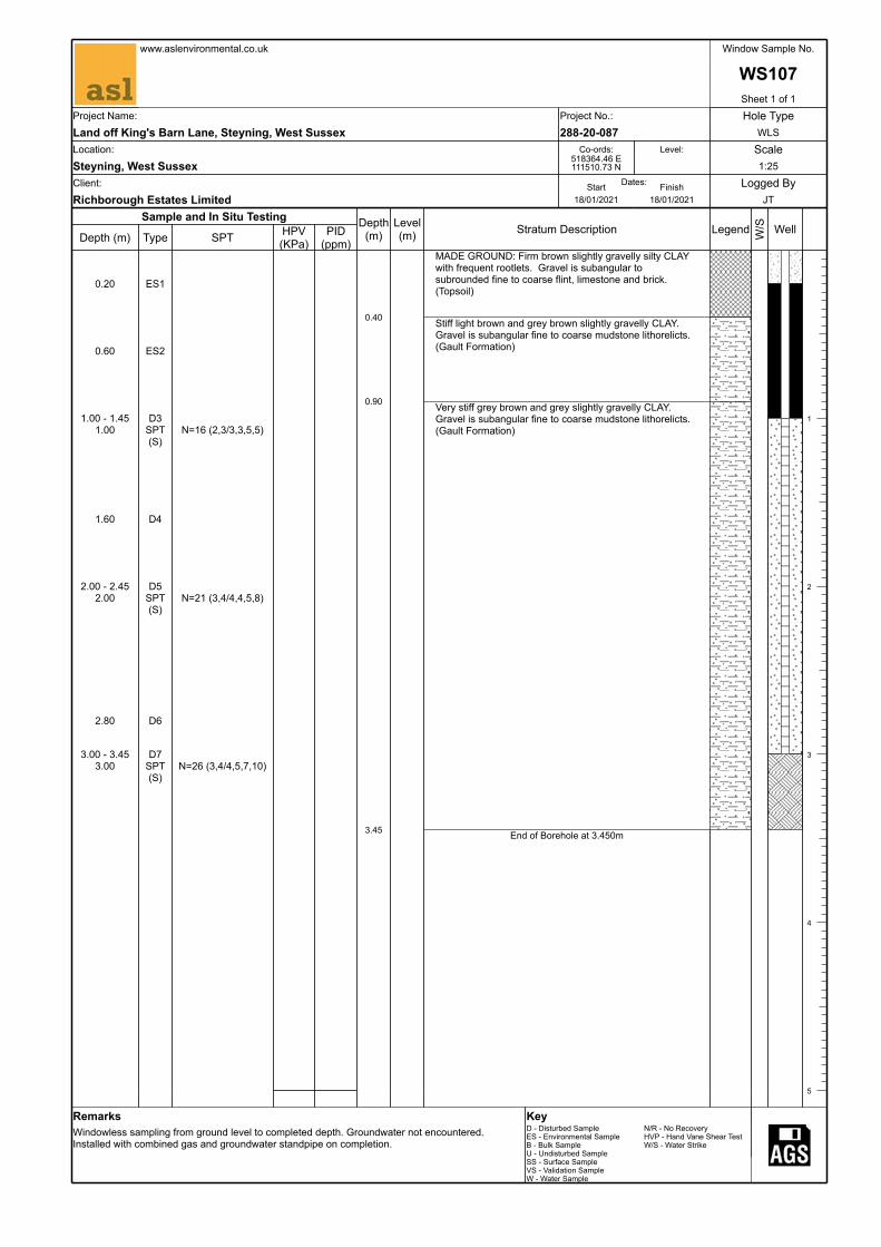
MADE GROUND: Firm brown slightly gravelly silty CLAY with frequent rootlets. Gravel is subangular to subrounded fine to coarse flint, limestone and brick. (Topsoil)
Stiff light brown and grey brown slightly gravelly CLAY. Gravel is subangular fine to coarse mudstone lithorelicts. (Gault Formation)
Very stiff grey brown and grey slightly gravelly CLAY. Gravel is subangular fine to coarse mudstone lithorelicts. (Gault Formation)
End of Borehole at 3.450m
Legend W/S Well
1
2
3
4
5
0.20 ES1
0.60 ES2
1.00 - 1.45 D31.00 SPT
(S)N=16 (2,3/3,3,5,5)
1.60 D4
2.00 - 2.45 D52.00 SPT
(S)N=21 (3,4/4,4,5,8)
2.80 D6
3.00 - 3.45 D73.00 SPT
(S)N=26 (3,4/4,5,7,10)
www.aslenvironmental.co.uk Window Sample No.
WS107Sheet 1 of 1
Project Name: Project No.: Hole TypeLand off King's Barn Lane, Steyning, West Sussex 288-20-087 WLSLocation: Co-ords: Level: ScaleSteyning, West Sussex
518364.46 E 111510.73 N 1:25
Client: Dates:Start Finish Logged ByRichborough Estates Limited 18/01/2021 18/01/2021 JT
RemarksWindowless sampling from ground level to completed depth. Groundwater not encountered. Installed with combined gas and groundwater standpipe on completion.
KeyD - Disturbed Sample N/R - No RecoveryES - Environmental Sample HVP - Hand Vane Shear TestB - Bulk Sample W/S - Water StrikeU - Undisturbed SampleSS - Surface SampleVS - Validation SampleW - Water Sample

Sample and In Situ Testing
Depth (m) Type SPT HPV (KPa)
PID (ppm)
Depth(m)
0.40
3.00
Level(m) Stratum Description
MADE GROUND: Firm brown slightly gravelly silty CLAY with frequent rootlets. Gravel is subangular to subrounded fine to coarse brick, flint and limestone. (Topsoil)
Stiff grey brown locally slightly sandy silty CLAY. (Gault Formation)
End of Borehole at 3.000m
Legend W/S Well
1
2
3
4
5
0.20 ES1
0.60 ES2
1.30 D31.30 D4
1.90 D5
2.30 D6
3.00 D7
www.aslenvironmental.co.uk Window Sample No.
WS109Sheet 1 of 1
Project Name: Project No.: Hole TypeLand off King's Barn Lane, Steyning, West Sussex 288-20-087 WLSLocation: Co-ords: Level: ScaleSteyning, West Sussex
518345.09 E 111661.06 N 1:25
Client: Dates:Start Finish Logged ByRichborough Estates Limited 18/01/2021 18/01/2021 JT
RemarksWindowless sampling from ground level to completed depth. Groundwater not encountered. Installed with combined gas and groundwater standpipe on completion.
KeyD - Disturbed Sample N/R - No RecoveryES - Environmental Sample HVP - Hand Vane Shear TestB - Bulk Sample W/S - Water StrikeU - Undisturbed SampleSS - Surface SampleVS - Validation SampleW - Water Sample

Sample and In Situ Testing
Depth (m) Type SPT HPV (KPa)
PID (ppm)
Depth(m)
0.40
2.10
3.00
Level(m) Stratum Description
Firm brown silty CLAY with frequent rootlets and rare subangular fine to coarse gravel of limestone. (Topsoil)
Firm stiff orange brown slightly sandy CLAY with rare subangular to subrounded fine to coarse gravel of limestone. (Possible Head)
Becoming sandy
Stiff grey brown locally slightly sandy CLAY. (Gault Formation)
End of Borehole at 3.000m
Legend W/S Well
1
2
3
4
5
0.20 ES1
0.70 ES2
1.20 D3
1.90 D4
2.40 D5
3.00 D6
www.aslenvironmental.co.uk Window Sample No.
WS110Sheet 1 of 1
Project Name: Project No.: Hole TypeLand off King's Barn Lane, Steyning, West Sussex 288-20-087 WLSLocation: Co-ords: Level: ScaleSteyning, West Sussex
518456.17 E 111650.61 N 1:25
Client: Dates:Start Finish Logged ByRichborough Estates Limited 18/01/2021 18/01/2021 JT
RemarksWindowless sampling from ground level to completed depth. Groundwater not encountered. Installed with combined gas and groundwater standpipe on completion.
KeyD - Disturbed Sample N/R - No RecoveryES - Environmental Sample HVP - Hand Vane Shear TestB - Bulk Sample W/S - Water StrikeU - Undisturbed SampleSS - Surface SampleVS - Validation SampleW - Water Sample

Falling Head Permeability Test
Project No:
Project:
Date:Borehole No.:
Time (seconds)
Depth to Water (mbgl) Head
Head Ratio
(H/Ho)
Diameter of piezometer (or where surrounded by granular filter, the diameter of the filter)
80
0 0.11 2.81 1.0 Diameter of standpipe 501200 0.11 2.81 1.000 Top of response zone 1.003240 0.11 2.81 1.000 Base of response zone 3.006480 0.11 2.81 1.000 Length of response zone (saturated) 2.009960 0.11 2.81 1.000 L/D 25.0011700 0.11 2.81 1.000 Area 0.0019625
Starting Water Level 2.92
Time Interval (t1) 0Time Interval (t2) 11700
Intake Factor (F) 70.160 10.220 23.105 33.210 40.002 50.002 63.6588 7
Intake Factor (F) 3.6588Permeability (k) - General Method 0.00E+00 m/s
b = Soil flush with bottom in uniform soilc = Well or hole extended at impervious boundaryd = Well or hole extended in uniform soile = Soil in casing with bottom at impervious boundaryf = Soil in casing with bottom in uniform soilTest carried out in piezometer tube
a = Soil flush with bottom at impervious boundary
m bglm bgl
m
m2
m
Comments:
Test carried out in general accordance with the methodology set out in BS 5930:1999
secondsseconds
Method
mm
288-20-087Land off King’s Barn Lane, Steyning, West Sussex19/01/2021WS101A
mm
0.0001
0.0010
0.0100
0.1000
1.0000
0
500
1000
1500
2000
2500
3000
3500
4000
4500
5000
5500
6000
6500
7000
7500
8000
8500
9000
9500
10000
10500
11000
11500
12000
12500
Hea
d R
atio
H/H
o
Elapsed Time t (seconds)
WS101APage 1 of 13 pages

Falling Head Permeability Test
Project No:
Project:
Date:Borehole No.:
Time (seconds)
Depth to Water (mbgl) Head
Head Ratio
(H/Ho)
Diameter of piezometer (or where surrounded by granular filter, the diameter of the filter)
80
0 0.15 2.82 1.0 Diameter of standpipe 501080 0.15 2.82 1.000 Top of response zone 1.023060 0.15 2.82 1.000 Base of response zone 3.026300 0.15 2.82 1.000 Length of response zone (saturated) 2.009840 0.15 2.82 1.000 L/D 25.0011520 0.15 2.82 1.000 Area 0.0019625
Starting Water Level 2.97
Time Interval (t1) 0Time Interval (t2) 11520
Intake Factor (F) 70.160 10.220 23.105 33.210 40.002 50.002 63.6588 7
Intake Factor (F) 3.6588Permeability (k) - General Method 0.00E+00 m/s
b = Soil flush with bottom in uniform soilc = Well or hole extended at impervious boundaryd = Well or hole extended in uniform soile = Soil in casing with bottom at impervious boundaryf = Soil in casing with bottom in uniform soilTest carried out in piezometer tube
a = Soil flush with bottom at impervious boundary
m bglm bgl
m
m2
m
Comments:
Test carried out in general accordance with the methodology set out in BS 5930:1999
secondsseconds
Method
mm
288-20-087Land off King’s Barn Lane, Steyning, West Sussex19/01/2021WS101B
mm
0.0001
0.0010
0.0100
0.1000
1.0000
0
500
1000
1500
2000
2500
3000
3500
4000
4500
5000
5500
6000
6500
7000
7500
8000
8500
9000
9500
10000
10500
11000
11500
12000
12500
Hea
d R
atio
H/H
o
Elapsed Time t (seconds)
WS101BPage 2 of 13 pages

Falling Head Permeability Test
Project No:
Project:
Date:Borehole No.:
Time (seconds)
Depth to Water (mbgl) Head
Head Ratio
(H/Ho)
Diameter of piezometer (or where surrounded by granular filter, the diameter of the filter)
80
0 0.10 2.91 1.0 Diameter of standpipe 50300 0.10 2.91 1.000 Top of response zone 1.004320 0.16 2.85 0.979 Base of response zone 3.008340 0.16 2.85 0.979 Length of response zone (saturated) 2.009780 0.16 2.85 0.979 L/D 25.00
Area 0.0019625Starting Water Level 3.01
Time Interval (t1) 0Time Interval (t2) 9780
Intake Factor (F) 70.160 10.220 23.105 33.210 40.002 50.002 63.6588 7
Intake Factor (F) 3.6588Permeability (k) - General Method 1.14E-09 m/s
b = Soil flush with bottom in uniform soilc = Well or hole extended at impervious boundaryd = Well or hole extended in uniform soile = Soil in casing with bottom at impervious boundaryf = Soil in casing with bottom in uniform soilTest carried out in piezometer tube
a = Soil flush with bottom at impervious boundary
m bglm bgl
m
m2
m
Comments:
Test carried out in general accordance with the methodology set out in BS 5930:1999
secondsseconds
Method
mm
288-20-087Land off King’s Barn Lane, Steyning, West Sussex19/01/2021WS102
mm
0.0001
0.0010
0.0100
0.1000
1.0000
0
500
1000
1500
2000
2500
3000
3500
4000
4500
5000
5500
6000
6500
7000
7500
8000
8500
9000
9500
10000
10500
Hea
d R
atio
H/H
o
Elapsed Time t (seconds)
WS102Page 3 of 13 pages

Falling Head Permeability Test
Project No:
Project:
Date:Borehole No.:
Time (seconds)
Depth to Water (mbgl) Head
Head Ratio
(H/Ho)
Diameter of piezometer (or where surrounded by granular filter, the diameter of the filter)
80
0 0.14 1.18 1.0 Diameter of standpipe 50240 0.15 1.17 0.992 Top of response zone 1.072220 0.25 1.07 0.907 Base of response zone 3.075700 0.36 0.96 0.814 Length of response zone (saturated) 2.008880 0.42 0.90 0.763 L/D 25.00
Area 0.0019625Starting Water Level 1.32
Time Interval (t1) 0Time Interval (t2) 8880
Intake Factor (F) 70.160 10.220 23.105 33.210 40.002 50.002 63.6588 7
Intake Factor (F) 3.6588Permeability (k) - General Method 1.64E-08 m/s
288-20-087Land off King’s Barn Lane, Steyning, West Sussex19/01/2021WS103 - Test 1
f = Soil in casing with bottom in uniform soilTest carried out in piezometer tube
Method a = Soil flush with bottom at impervious boundaryb = Soil flush with bottom in uniform soilc = Well or hole extended at impervious boundaryd = Well or hole extended in uniform soile = Soil in casing with bottom at impervious boundary
seconds
mm
mmm bglm bgl
m
m2
m
Comments:
Test carried out in general accordance with the methodology set out in BS 5930:1999
seconds
0.0001
0.0010
0.0100
0.1000
1.0000
0
500
1000
1500
2000
2500
3000
3500
4000
4500
5000
5500
6000
6500
7000
7500
8000
8500
9000
9500
Hea
d R
atio
H/H
o
Elapsed Time t (seconds)
WS103 - Test 1Page 4 of 13 pages

Falling Head Permeability Test
Project No:
Project:
Date:Borehole No.:
Time (seconds)
Depth to Water (mbgl) Head
Head Ratio
(H/Ho)
Diameter of piezometer (or where surrounded by granular filter, the diameter of the filter)
80
0 0.14 1.36 1.0 Diameter of standpipe 50360 0.34 1.16 0.853 Top of response zone 1.07540 0.42 1.08 0.794 Base of response zone 3.071500 0.44 1.06 0.779 Length of response zone (saturated) 2.008100 0.46 1.04 0.765 L/D 25.0010200 0.48 1.02 0.750 Area 0.001962512480 0.48 1.02 0.750 Starting Water Level 1.50
Time Interval (t1) 0Time Interval (t2) 12480
Intake Factor (F) 70.160 10.220 23.105 33.210 40.002 50.002 63.6588 7
Intake Factor (F) 3.6588Permeability (k) - General Method 1.24E-08 m/s
b = Soil flush with bottom in uniform soilc = Well or hole extended at impervious boundaryd = Well or hole extended in uniform soile = Soil in casing with bottom at impervious boundaryf = Soil in casing with bottom in uniform soilTest carried out in piezometer tube
a = Soil flush with bottom at impervious boundary
m bglm bgl
m
m2
m
Comments:
Test carried out in general accordance with the methodology set out in BS 5930:1999
secondsseconds
Method
mm
288-20-087Land off King’s Barn Lane, Steyning, West Sussex20/01/2021WS103 - Test 2
mm
0.0001
0.0010
0.0100
0.1000
1.0000
0
500
1000
1500
2000
2500
3000
3500
4000
4500
5000
5500
6000
6500
7000
7500
8000
8500
9000
9500
10000
10500
11000
11500
12000
12500
13000
13500
Hea
d R
atio
H/H
o
Elapsed Time t (seconds)
WS103 - Test 2Page 5 of 13 pages

Falling Head Permeability Test
Project No:
Project:
Date:Borehole No.:
Time (seconds)
Depth to Water (mbgl) Head
Head Ratio
(H/Ho)
Diameter of piezometer (or where surrounded by granular filter, the diameter of the filter)
80
0 0.18 2.45 1.0 Diameter of standpipe 501620 0.18 2.45 1.000 Top of response zone 1.105220 0.20 2.43 0.992 Base of response zone 3.107080 0.20 2.43 0.992 Length of response zone (saturated) 2.009480 0.20 2.43 0.992 L/D 25.0014100 0.20 2.43 0.992 Area 0.0019625
Starting Water Level 2.63
Time Interval (t1) 0Time Interval (t2) 14100
Intake Factor (F) 70.160 10.220 23.105 33.210 40.002 50.002 63.6588 7
Intake Factor (F) 3.6588Permeability (k) - General Method 3.12E-10 m/s
b = Soil flush with bottom in uniform soilc = Well or hole extended at impervious boundaryd = Well or hole extended in uniform soile = Soil in casing with bottom at impervious boundaryf = Soil in casing with bottom in uniform soilTest carried out in piezometer tube
a = Soil flush with bottom at impervious boundary
m bglm bgl
m
m2
m
Comments:
Test carried out in general accordance with the methodology set out in BS 5930:1999
secondsseconds
Method
mm
288-20-087Land off King’s Barn Lane, Steyning, West Sussex20/01/2021WS104
mm
0.0001
0.0010
0.0100
0.1000
1.0000
0
500
1000
1500
2000
2500
3000
3500
4000
4500
5000
5500
6000
6500
7000
7500
8000
8500
9000
9500
10000
10500
11000
11500
12000
12500
13000
13500
14000
14500
15000
Hea
d R
atio
H/H
o
Elapsed Time t (seconds)
WS104Page 6 of 13 pages
Falling Head Permeability Test
Project No:
Project:
Date:Borehole No.:
Time (seconds)
Depth to Water (mbgl) Head
Head Ratio
(H/Ho)
Diameter of piezometer (or where surrounded by granular filter, the diameter of the filter)
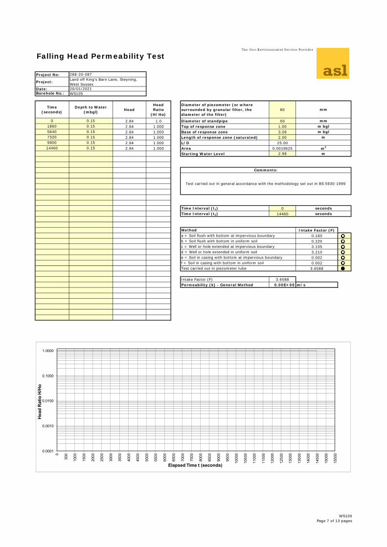
80
0 0.15 2.84 1.0 Diameter of standpipe 501860 0.15 2.84 1.000 Top of response zone 1.005640 0.15 2.84 1.000 Base of response zone 3.097320 0.15 2.84 1.000 Length of response zone (saturated) 2.009900 0.15 2.84 1.000 L/D 25.0014460 0.15 2.84 1.000 Area 0.0019625
Starting Water Level 2.99
Time Interval (t1) 0Time Interval (t2) 14460
Intake Factor (F) 70.160 10.220 23.105 33.210 40.002 50.002 63.6588 7
Intake Factor (F) 3.6588Permeability (k) - General Method 0.00E+00 m/s
b = Soil flush with bottom in uniform soilc = Well or hole extended at impervious boundaryd = Well or hole extended in uniform soile = Soil in casing with bottom at impervious boundaryf = Soil in casing with bottom in uniform soilTest carried out in piezometer tube
a = Soil flush with bottom at impervious boundary
m bglm bgl
m
m2
m
Comments:
Test carried out in general accordance with the methodology set out in BS 5930:1999
secondsseconds
Method
mm
288-20-087Land off King’s Barn Lane, Steyning, West Sussex20/01/2021WS105
mm
0.0001
0.0010
0.0100
0.1000
1.0000
0
500
1000
1500
2000
2500
3000
3500
4000
4500
5000
5500
6000
6500
7000
7500
8000
8500
9000
9500
10000
10500
11000
11500
12000
12500
13000
13500
14000
14500
15000
15500
Hea
d R
atio
H/H
o
Elapsed Time t (seconds)
WS105Page 7 of 13 pages

Falling Head Permeability Test
Project No:
Project:
Date:Borehole No.:
Time (seconds)
Depth to Water (mbgl) Head
Head Ratio
(H/Ho)
Diameter of piezometer (or where surrounded by granular filter, the diameter of the filter)
80
0 0.36 2.55 1.0 Diameter of standpipe 50360 0.36 2.55 1.000 Top of response zone 1.052160 0.36 2.55 1.000 Base of response zone 3.056300 0.36 2.55 1.000 Length of response zone (saturated) 2.0010080 0.36 2.55 1.000 L/D 25.0012000 0.36 2.55 1.000 Area 0.0019625
Starting Water Level 2.91
Time Interval (t1) 0Time Interval (t2) 12000
Intake Factor (F) 70.160 10.220 23.105 33.210 40.002 50.002 63.6588 7
Intake Factor (F) 3.6588Permeability (k) - General Method 0.00E+00 m/s
b = Soil flush with bottom in uniform soilc = Well or hole extended at impervious boundaryd = Well or hole extended in uniform soile = Soil in casing with bottom at impervious boundaryf = Soil in casing with bottom in uniform soilTest carried out in piezometer tube
a = Soil flush with bottom at impervious boundary
m bglm bgl
m
m2
m
Comments:
Test carried out in general accordance with the methodology set out in BS 5930:1999
secondsseconds
Method
mm
288-20-087Land off King’s Barn Lane, Steyning, West Sussex19/01/2021WS106
mm
0.0001
0.0010
0.0100
0.1000
1.0000
0
500
1000
1500
2000
2500
3000
3500
4000
4500
5000
5500
6000
6500
7000
7500
8000
8500
9000
9500
10000
10500
11000
11500
12000
12500
13000
Hea
d R
atio
H/H
o
Elapsed Time t (seconds)
WS106Page 8 of 13 pages

Falling Head Permeability Test
Project No:
Project:
Date:Borehole No.:
Time (seconds)
Depth to Water (mbgl) Head
Head Ratio
(H/Ho)
Diameter of piezometer (or where surrounded by granular filter, the diameter of the filter)
80
0 0.20 2.70 1.0 Diameter of standpipe 502100 0.30 2.60 0.963 Top of response zone 1.003300 0.41 2.49 0.922 Base of response zone 3.007440 0.61 2.29 0.848 Length of response zone (saturated) 2.0010680 0.76 2.14 0.793 L/D 25.00
Area 0.0019625Starting Water Level 2.90
Time Interval (t1) 0Time Interval (t2) 10680
Intake Factor (F) 70.160 10.220 23.105 33.210 40.002 50.002 63.6588 7
Intake Factor (F) 3.6588Permeability (k) - General Method 1.17E-08 m/s
b = Soil flush with bottom in uniform soilc = Well or hole extended at impervious boundaryd = Well or hole extended in uniform soile = Soil in casing with bottom at impervious boundaryf = Soil in casing with bottom in uniform soilTest carried out in piezometer tube
a = Soil flush with bottom at impervious boundary
m bglm bgl
m
m2
m
Comments:
Test carried out in general accordance with the methodology set out in BS 5930:1999
secondsseconds
Method
mm
288-20-087Land off King’s Barn Lane, Steyning, West Sussex19/01/2021WS107 - Test 1
mm
0.0001
0.0010
0.0100
0.1000
1.0000
0
500
1000
1500
2000
2500
3000
3500
4000
4500
5000
5500
6000
6500
7000
7500
8000
8500
9000
9500
10000
10500
11000
11500
Hea
d R
atio
H/H
o
Elapsed Time t (seconds)
WS107 - Test 1Page 9 of 13 pages
Falling Head Permeability Test
Project No:
Project:
Date:Borehole No.:
Time (seconds)
Depth to Water (mbgl) Head
Head Ratio
(H/Ho)
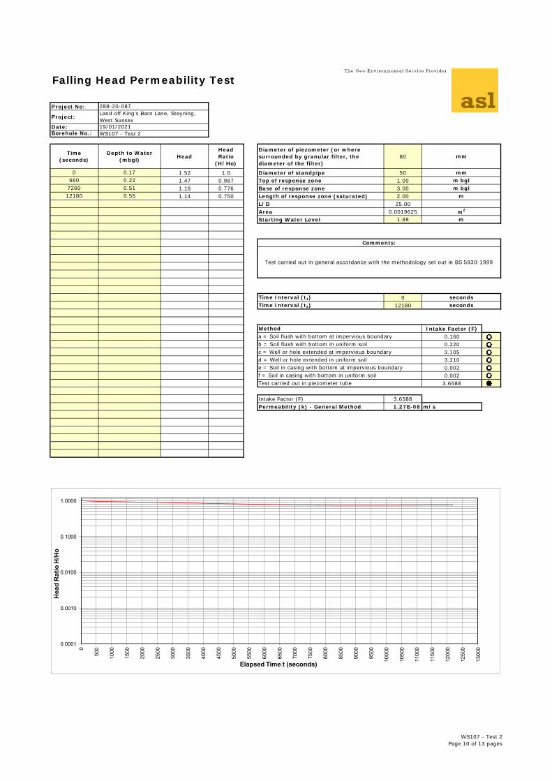
Diameter of piezometer (or where surrounded by granular filter, the diameter of the filter)
80
0 0.17 1.52 1.0 Diameter of standpipe 50660 0.22 1.47 0.967 Top of response zone 1.007260 0.51 1.18 0.776 Base of response zone 3.0012180 0.55 1.14 0.750 Length of response zone (saturated) 2.00
L/D 25.00Area 0.0019625Starting Water Level 1.69
Time Interval (t1) 0Time Interval (t2) 12180
Intake Factor (F) 70.160 10.220 23.105 33.210 40.002 50.002 63.6588 7
Intake Factor (F) 3.6588Permeability (k) - General Method 1.27E-08 m/s
b = Soil flush with bottom in uniform soilc = Well or hole extended at impervious boundaryd = Well or hole extended in uniform soile = Soil in casing with bottom at impervious boundaryf = Soil in casing with bottom in uniform soilTest carried out in piezometer tube
a = Soil flush with bottom at impervious boundary
m bglm bgl
m
m2
m
Comments:
Test carried out in general accordance with the methodology set out in BS 5930:1999
secondsseconds
Method
mm
288-20-087Land off King’s Barn Lane, Steyning, West Sussex19/01/2021WS107 - Test 2
mm
0.0001
0.0010
0.0100
0.1000
1.0000
0
500
1000
1500
2000
2500
3000
3500
4000
4500
5000
5500
6000
6500
7000
7500
8000
8500
9000
9500
10000
10500
11000
11500
12000
12500
13000
Hea
d R
atio
H/H
o
Elapsed Time t (seconds)
WS107 - Test 2Page 10 of 13 pages
Falling Head Permeability Test
Project No:
Project:
Date:Borehole No.:
Time (seconds)
Depth to Water (mbgl) Head
Head Ratio
(H/Ho)
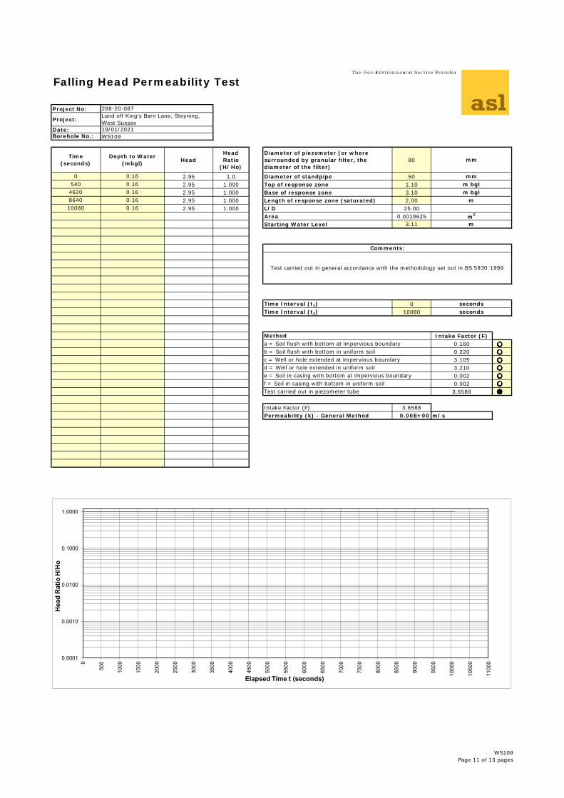
Diameter of piezometer (or where surrounded by granular filter, the diameter of the filter)
80
0 0.16 2.95 1.0 Diameter of standpipe 50540 0.16 2.95 1.000 Top of response zone 1.104620 0.16 2.95 1.000 Base of response zone 3.108640 0.16 2.95 1.000 Length of response zone (saturated) 2.0010080 0.16 2.95 1.000 L/D 25.00
Area 0.0019625Starting Water Level 3.11
Time Interval (t1) 0Time Interval (t2) 10080
Intake Factor (F) 70.160 10.220 23.105 33.210 40.002 50.002 63.6588 7
Intake Factor (F) 3.6588Permeability (k) - General Method 0.00E+00 m/s
b = Soil flush with bottom in uniform soilc = Well or hole extended at impervious boundaryd = Well or hole extended in uniform soile = Soil in casing with bottom at impervious boundaryf = Soil in casing with bottom in uniform soilTest carried out in piezometer tube
a = Soil flush with bottom at impervious boundary
m bglm bgl
m
m2
m
Comments:
Test carried out in general accordance with the methodology set out in BS 5930:1999
secondsseconds
Method
mm
288-20-087Land off King’s Barn Lane, Steyning, West Sussex19/01/2021WS109
mm
0.0001
0.0010
0.0100
0.1000
1.0000
0
500
1000
1500
2000
2500
3000
3500
4000
4500
5000
5500
6000
6500
7000
7500
8000
8500
9000
9500
10000
10500
11000
Hea
d R
atio
H/H
o
Elapsed Time t (seconds)
WS109Page 11 of 13 pages
Falling Head Permeability Test
Project No:
Project:
Date:Borehole No.:
Time (seconds)
Depth to Water (mbgl) Head
Head Ratio
(H/Ho)
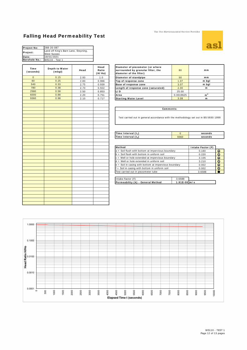
Diameter of piezometer (or where surrounded by granular filter, the diameter of the filter)
80
0 0.15 2.93 1.0 Diameter of standpipe 5060 0.25 2.83 0.966 Top of response zone 1.07540 0.33 2.75 0.939 Base of response zone 3.07780 0.38 2.70 0.922 Length of response zone (saturated) 2.002580 0.58 2.50 0.853 L/D 25.006000 0.88 2.20 0.751 Area 0.00196259360 0.98 2.10 0.717 Starting Water Level 3.08
Time Interval (t1) 0Time Interval (t2) 9360
Intake Factor (F) 70.160 10.220 23.105 33.210 40.002 50.002 63.6588 7
Intake Factor (F) 3.6588Permeability (k) - General Method 1.91E-08 m/s
mm
288-20-087Land off King’s Barn Lane, Steyning, West Sussex19/01/2021WS110 - Test 1
mm
a = Soil flush with bottom at impervious boundary
m bglm bgl
m
m2
m
Comments:
Test carried out in general accordance with the methodology set out in BS 5930:1999
secondsseconds
Method
b = Soil flush with bottom in uniform soilc = Well or hole extended at impervious boundaryd = Well or hole extended in uniform soile = Soil in casing with bottom at impervious boundaryf = Soil in casing with bottom in uniform soilTest carried out in piezometer tube
0.0001
0.0010
0.0100
0.1000
1.0000
0
500
1000
1500
2000
2500
3000
3500
4000
4500
5000
5500
6000
6500
7000
7500
8000
8500
9000
9500
10000
Hea
d R
atio
H/H
o
Elapsed Time t (seconds)
WS110 - TEST 1Page 12 of 13 pages
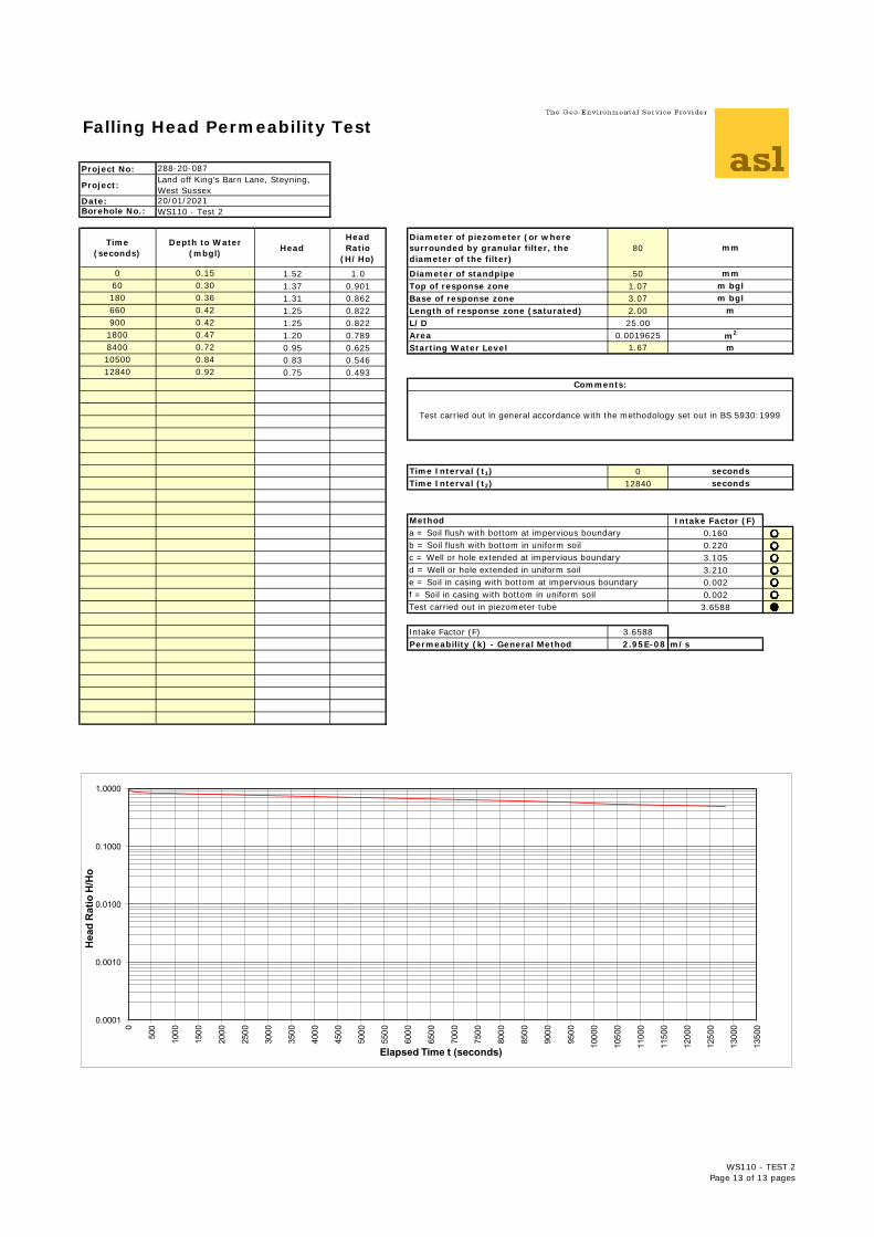
Falling Head Permeability Test
Project No:
Project:
Date:Borehole No.:
Time (seconds)
Depth to Water (mbgl) Head
Head Ratio
(H/Ho)
Diameter of piezometer (or where surrounded by granular filter, the diameter of the filter)
80
0 0.15 1.52 1.0 Diameter of standpipe 5060 0.30 1.37 0.901 Top of response zone 1.07180 0.36 1.31 0.862 Base of response zone 3.07660 0.42 1.25 0.822 Length of response zone (saturated) 2.00900 0.42 1.25 0.822 L/D 25.001800 0.47 1.20 0.789 Area 0.00196258400 0.72 0.95 0.625 Starting Water Level 1.6710500 0.84 0.83 0.54612840 0.92 0.75 0.493
Time Interval (t1) 0Time Interval (t2) 12840
Intake Factor (F) 70.160 10.220 23.105 33.210 40.002 50.002 63.6588 7
Intake Factor (F) 3.6588Permeability (k) - General Method 2.95E-08 m/s
b = Soil flush with bottom in uniform soilc = Well or hole extended at impervious boundaryd = Well or hole extended in uniform soile = Soil in casing with bottom at impervious boundaryf = Soil in casing with bottom in uniform soilTest carried out in piezometer tube
a = Soil flush with bottom at impervious boundary
m bglm bgl
m
m2
m
Comments:
Test carried out in general accordance with the methodology set out in BS 5930:1999
secondsseconds
Method
mm
288-20-087Land off King’s Barn Lane, Steyning, West Sussex20/01/2021WS110 - Test 2
mm
0.0001
0.0010
0.0100
0.1000
1.0000
0
500
1000
1500
2000
2500
3000
3500
4000
4500
5000
5500
6000
6500
7000
7500
8000
8500
9000
9500
10000
10500
11000
11500
12000
12500
13000
13500
Hea
d R
atio
H/H
o
Elapsed Time t (seconds)
WS110 - TEST 2Page 13 of 13 pages