ashrae 90.1 – 2010 bc chapter • active member of ches and aspe • mechanical team lead at prism...
TRANSCRIPT

ASHRAE 90.1 – 2010 Understanding Code Compliance and Energy Efficiency
Stephen Kooiman, P.Eng., MASc, Mechanical Team Lead CIPHEX West 2016 November 2, 2016

2
Introductions
Prism Engineering provides consulting services to address technical, behavioural and organizational aspects of Energy Management We design and implement cost effective approaches to address comfort, efficiency and reliability.

3
Your Presenter
Stephen Kooiman, P.Eng, M.A.Sc. • Past President of the ASHRAE BC Chapter • Active member of CHES and ASPE • Mechanical Team Lead at Prism Engineering • M.A.Sc. in thermal fluid dynamics • Specializes in energy upgrades, renovations and
capital renewal projects for HVAC , plumbing systems, controls in the Institutional, Healthcare Commercial and Industrial sectors
3

4
Before we get Started • Who is in the room
– Architects – Engineers – Contractors – Building Operators – Property or Facility Managers – Building Owners
• Familiarity with ASHRAE 90.1

5
Agenda 1. Introduction to the Standard 2. Administration and Enforcement 3. Core Components
i. Overview (Section 4) ii. Heating Ventilation and Air Conditioning
(Section 6) iii. Service Water Heating (Section 7) iv. Energy Cost Budget Method (Section 11)
4. Review Q&A Throughout

PURPOSE OF ASHRAE STANDARDS

7
Introduction to ASHRAE American Society of Heating, Refrigeration, and Air-Conditioning Engineers
– To advance the arts and sciences of heating, ventilation, air conditioning and refrigeration to serve humanity and promote a sustainable world.

8
It’s the “Reference” Association:
ASHRAE Referred to in Codes

9
Codes, Standards and Guidelines What is a Code?
• Least Safe… • Least Strong… • Least energy efficient … Building
allowed by Law
Code vs. Standards

ASHRAE 90.1

11
Introduction to ASHRAE 90.1 Why is 90.1 - 2010 important
• Part 10 — Energy and Water Efficiency
Adoption of 90.1 • Vancouver: BC:
• v2001 in 2004 • v2007 in 2009 v2004 in 2008 • v2010 in 2013 v2010 in 2013 • v2013 in ???

12
Purpose ASHRAE 90.1 Purpose:
• To establish the minimum energy efficiency requirements of buildings and building systems
Application: • to all buildings except low-rise residential • New Buildings, Expansions, Renovations, Capital
Equipment Upgrades
On “Continuous Maintenance” since 2001

13
Energy Impact of Ashrae 90.1

14
Climate Zones • Lower Mainland: 4C • Vancouver: 5C

ADMINISTRATION & ENFORCEMENT

16
90.1 Compliance
Mandatory Provisions
(required for most compliance
options)
Building System (technical sections)
Energy Code Compliance
Prescriptive Option
Energy Cost Budget
Trade Off Option
Simplified
5. Envelope
6. HVAC
9. Lighting
7. SWH
8. Power
10. Other

17
Where 90.1 Applies? • New Buildings
– Comply with Sections 5-10 or 11
• Additions – Comply with Sections 5-10 or 11*
*Exception © climate zone dependent
90.1 Compliant
New Building
Existing Building
90.1 Compliant
Addition
Existing Building (Energy
Upgrades)
Non-compliant
Addition
ECB Section 11
Or
If not possible
Section 4.1.1.1 & 4.1.1.2

18
Where 90.1 Applies? • Changing Space Occupancy
– Entire space shall comply as if new construction
Existing Warehouse
New Office
To Existing HVAC
Section 4.1.1.4 & 4.1.1.5

19
Where 90.1 Applies? • Alterations of Existing Building
– Components shall comply with Sections 5-10
– Overall comprehensive design shall not exceed energy use for modelled standard –Exception for “Extensive
revisions to other systems”
Section 4.1.1.4 & 4.1.1.5

20
Alterations to Existing Mechanical Systems • The following must be in compliance:
– New HVAC equipment – Service water heating equipment – New piping & insulation – New ductwork and insulation
Section 4.2.1.3.b 6.1.1.3 & 7.1.1.3

21
Compliance Documentation • Shall be made available to the building official to
demonstrate compliance – Including calculations, worksheets, forms, vendor
literature
• O&M manuals and record drawings within 90 days
Section 4.2.2

HVAC

23
Ashrae 90.1 Section 6 HVAC • Conformance Paths

24
6.3 Simplified Approach • Simplified method applies for:
– For Buildings 1 or 2 stories – Total area of <25,000 sqft
• Must meet 17 requirements a) Thermal zoning – Units must serve a single zone b) Variable flow per 6.4.3.1 c & e) Cooling and heating equipment efficiencies d) Air side economizers for units >54 MBH cooling
capacity (6.5.1)

25
6.3 Simplified Approach f) Energy recovery efficiencies (6.5.6.1) g) Controls:
g) Manual changeover or dual setpoint thermostat i) No simultaneous heating & cooling for humidity control j) HVAC controlled on occupancy o) Interlock thermostats for units serving the same zone p) Optimum start (systems > 10,000 cfm) q) Demand control ventilation
h) Heat pump secondary heating controls k & l) Piping & duct insulation

26
6.3 Simplified Approach m) Air balancing n) Outdoor air intake & exhaust (6.4.3.4) Sample from 90.1 - 2010

27
6.4 Mandatory Provisions A. Equipment Efficiencies B. Calculations C. Controls D. HVAC Construction and Insulation

28
A. Equipment Efficiencies • Tables:
– Table 6.8.1A – Air conditioners and condensing units – Table 6.8.1B – Heat pumps – Table 6.8.1C – Water chillers – Table 6.8.1D – Packaged terminal AC/HP – Table 6.8.1E – Furnaces, duct furnaces, and unit heaters – Table 6.8.1F – Boilers – Table 6.8.1G – Heat rejection equipment – Table 6.8.1H – Heat transfer equipment (liquid-to-liquid HX) – Table 6.8.1 I – Variable Refrigerant Flow (VRF) A.C. – Table 6.8.1J – VRF air-to-air & applied heat pumps – Table 6.8.1K – AC serving computer rooms
Section 6.4.1

29
Sample Table
30
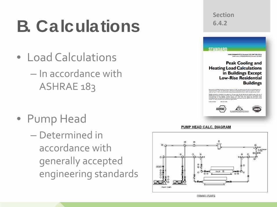
B. Calculations • Load Calculations
– In accordance with ASHRAE 183
• Pump Head – Determined in
accordance with generally accepted engineering standards
Section 6.4.2

31
C. Controls • Sections:
• Zone Thermostat • Off Hours • Ventilation Systems
Section 6.4.3

32
C. Zone Thermostat Controls • Zone Thermostat controls
– Required for each zone – Dead band controls of at
least 5°F
60’
80’
90’
Zone 1
Zone 2
Zone 3
Zone 4
20’ Typical
10’ Typical
T
T
T
T
Section 6.4.3.1

33
C. Off Hours Controls
• Automatic shutdown • Setback controls • Optimum start • Zone isolation
Section 6.4.3.3

34
C. Ventilation Controls
• O/A intake & exhaust systems shall be equipped with motorized dampers that will automatically shut when the systems or spaces served are not in use
• Exceptions: – BDD acceptable 3 stories* – Less than 300 cfm – Serving unconditioned space – Type 1 kitchen exhaust hoods
TABLE 6.4.3.4.3 Maximum Damper Leakage (cfm per ft2 at 1” w.g.)
Climate Zone Ventilation Air Intake Exhaust/Relief
Non-motorized Motorized Non-motorized Motorized
1,2 Any height
--- 20
--- 4
--- 20
--- 4
3 Any height
--- 20
--- 10
--- 20
--- 10
4, 5b, 5c < 3 stories ≥ 3 stories
--- Not allowed Not allowed
--- 10 10
--- 20
Not allowed
--- 10 10
5a, 6, 7, 8 < 3 stories ≥ 3 stories
--- Not allowed Not allowed
--- 4 4
--- 20
Not allowed
--- 4 4
Section 6.4.3.4

35
C. Ventilation Controls
• Automatic controls for Fans > 0.75 HP • Heat Pump aux. heating controls • Humidification and dehumidification • Freeze protection and snow melting systems
Sections 6.4.3.5, 6.4.3.6, 6.4.3.7, 6.4.3.8, 6.4.3.10

36
C. Demand Control Ventilation • Demand control ventilation (DCV*) required
for spaces > 500 ft2 and > 40 people / 1000 ft2 that are served by any of these: – Air-side economizer, or – Auto modulation of O.A. damper, or – Design O.A. air flow > 3000 cfm
Section 6.4.3.9

37
D. HVAC Construction and Insulation • Duct Insulation: per 6.8.2A & B
Section 6.4.4.1.2

38
D. Insulation • Piping Insulation: Per 6.8.3A & B
Section 6.4.4.1.2

39
D. Ductwork Leakage & Testing • Ductwork and all plenums with pressure class
ratings shall include sealing of all transverse joints, longitudinal seams, and duct wall penetrations.
• Meet requirements of leakage tests. • Duct tape or other pressure-sensitive tape
shall not be used as the primary sealant unless certified.
Sealant
Metal Duct
Transverse
Sealant
Longitudinal Joint
Section 6.4.4.1.2

40
D. Ductwork Leakage & Testing • Ductwork operating at static pressures
exceeding 3 in wc and all outdoor ductwork shall be leak tested
Section 6.4.4.2.2

41
6.5 Prescriptive Path A. Economizers B. Simultaneous Heating and Cooling C. Air System Design D. Hydronic System Design E. Heat Rejection Equipment F. Energy Recovery G. Exhaust Systems H. Radiant Heating and Hot Gas Bypass

42
A. Economizers • Economizers
– Cooling systems shall have air or water economizer
– Air Side: • Sequencing with cooling
equipment, High limit shut off • Dampers meeting section
6.4.3, c/w relief dampers
– Water Side: • 100% cooling load at 40F,
Maximum pressure drop of 15’, Integrated controls
Section 6.5.1

43
Waterside Economizer Plate-and-Frame Heat Exchanger
distribution pump
plate-and-frame heat exchanger
In-direct cooling of chilled water from cooling tower. Avoids cross-contamination.

44
B. Simultaneous Htg/Clg
• Simultaneous Heating and Cooling Limitations – Zone controls preventing reheating/re-cooling – Hydronic controls eliminating mixing HW & CHW
– 3 Pipe hydronic system not permitted – Heat pump water loop
– Dead band of 20F b/w heating and cooling
– Humidity controls to prevent reheat
Section 6.5.2

45
C. Air System Design • Fan system Power Limitations
– Fan motor operation limits
Section 6.5.3.1

46
C. Air System Design • VAV Fan Control
– Fans 10HP and larger require variable speed capabilities
– Sensor located at a maximum of 1/3rd the design static pressure
– Setpoint reset
Section 6.5.3.2

47
D. Hydronic System Design • Pumps > 10 HP require variable speed
operation • Temperature Reset on Chilled and Hot water
systems > 300MBH • Flow isolation for offline chillers and boilers
Section 6.5.4.1

48
D. Hydronic System Design • CHW piping sizing based on pump operating
hours per year
Section 6.5.4.1

49
Variable-Primary-Flow (VPF) Systems
two-way valve
variable-flow pumps
control valve
check valves
optional bypass with three-way valve
• Flow of water varies through entire system • Flow is monitored, and controlled between upper and lower limits • specified by the chiller manufacturer • Improved overall system efficiency through variable flow control

50
E. Heat Rejection Equipment • Motors >7.5 HP require to operate at 2/3
speed or less with automatic controls
Section 6.5.5

51
F. Energy Recovery • 6.5.6 Energy Recovery
– Exhaust energy recovery required when exceeds table 6.5.6.1
– Shall be 50% effective – Condensers shall service preheat service water*
Section 6.5.6

52
Schematic of the Plate Heat Exchanger

53
Schematic of the Recovery Wheel

54
Schematic of the Heat Recovery Glycol Loop
• This system is attractive in upgrades of existing systems when the exhaust fans are located far from the supply fans.
• It is also often used in Hospital upgrades due to 100% separation of exhaust and supply flows.

55
G. Exhaust Systems • Kitchen Hoods
o >5000 cfm require DCV
• Labs o Demand Control Ventilation or o Heat recovery system
Section 6.5.7

56
H. Radiant Heating & Hot Gas Bypass • 6.5.8 Radiant Heating Systems
• Only type of heating permitted for unenclosed spaces
• 6.5.9 Hot Gas Bypass Limitations
– Allowed for systems < 90 MBH
Section 6.5.8 & 6.5.9

57

58
6.7 Submittals • AHJ may request compliance documentation
(4.2.2)
• Required within 90 days of substantial completion: – Record drawings – O&M manuals – System Balancing reports – System commissioning report
• Detailed plan required in specifications if >50,000 sqft
Section 6.7

SERVICE WATER HEATING

60
Ashrae 90.1 Section 7 - Service Water Heating

61
1. Load calculations 2. Equipment efficiency 3. Service hot water piping insulation 4. Service water controls 5. Pools 6. Heat traps
Mandatory Requirements
Section 7.4

62
• Minimum efficiencies are shown in Table 7.8 • Equipment not listed in Table 7.8 has no minimum
performance requirements.
• Exception: Water heaters and hot water supply boilers > 140 gal storage capacity don’t have to meet standby loss (SL) requirements when • tank surface is thermally insulated to R-12.5, and • a standing pilot light is not installed, and • gas- or oil-fired water heaters have a flue
damper or fan-assisted combustion.”
Equipment Efficiencies Section 7.4.2

63
Example - Portion of Table 7.8
Equipment Type Size Category Sub-category or Rating Condition
Performance Required, (EF=Efficiency Factor SL=Standby Losses)
Gas Storage Water Heaters
≤ 75,000 Btu/h ≥ 20 gallons 0.67-0 %19V
(EF)
> 75,000 Btu/h < 4000 (Btu/h)/gal. min. 80% Et & max.
[ Q/800 + 110 √¯ V ] (SL), Btu/h
Hot Water Supply Boilers, Gas
≥ 4000 (Btu/h)/ gal. and ≥ 10 gal.
min. 80% Et & max.
[ Q/800 + 110 √¯ V ] (SL), Btu/h
Hot Water Supply Boilers, Oil
≥ 4000 (Btu/h)/ gal. and ≥ 10 gal.
min. 78% Et & max.
[ Q/800 + 110 √¯ V ] (SL), Btu/h
Heat pump pool heater All 50F DB & 44.2F WB o.a.
& 80F entering water. 4.0 COP
Note: Q = nameplate input rating (Btu/h); V = tank volume (gallons); Et = thermal efficiency

64
Service HW Insulation • The following shall comply with
Table 6.8.3 in the HVAC Section 6: – Recirculating system piping, including
supply and return piping. – Nonrecirculating storage system --
• First 8 ft of outlet piping. • Inlet pipe between storage tank
and heat trap. – Externally-heated pipes
(heat trace or impedance heating)
Section 7.4.3

65
Service Water Controls • Temperature controls • Maintenance controls • Outlet temperature control to 110F for Lav • Circulating pump enable controls
Section 7.4.4

66
Heat Traps • Vertical pipe risers serving water heaters
with a non-recirculating systems shall have heat traps on both the inlet and outlet piping as close as practical
Heat Traps(required)First 8 ft of
outlet pipingmust beinsulated
HW Out
Inlet pipingmust beinsulated throughthis elbow
WaterHeater
CW In

67
Pools • Heaters shall be equipped
with readily accessible on-off switch.
• Heated pools shall have a pool cover
• High temp pools (+90F) shall have a minimum R-12 cover
• Shall have a time switch
Section 7.4.5

68
Prescriptive Path • Combined service and heating systems
acceptable if: – Standby losses do not exceed: or – Energy consumption will be less than two separate
plants; or – The combined input is 150 MBH
Or • Energy Cost Budget Method (Section 11)
( )n
pmd 4003.13 +×
Section 7.5.1

OTHER EQUIPMENT

70
Other Equipment • Electric Motors
– Energy Policy Act 1992 compliant
• Booster Pumps
– Flow control with remote pressure sensors
– No main RP
Section 7.5.1

ENERGY COST BUDGET

72
Energy Cost Budget Mandatory Provisions
(Sections 5.4, 6.4, 7.4, 8.4, 9.4 & 10.4)
Prescriptive Path (X.5)
Energy Cost Budget (11)
Compliance
OR

73
ECB Compliance

74
Resources • ASHRAE 90.1
Users Guide • City of Vancouver
Checklists

WRAP UP

76
Lessons Learned • Nearly all mechanical and plumbing
systems are affected by 90.1
• New construction compliance paths well defined
• Extent of component upgrades can result in additional system modifications
• 90.1 is the least energy efficient system allowed by law

77
Thank you.
Stephen Kooiman, P.Eng., MASc Mechanical Team Lead Tel: 604-205-5509 [email protected] www.prismengineering.com 320 - 3605 Gilmore Way, Burnaby, BC V5G 4X5

78
Limits of Liability
This presentation was prepared by Prism Engineering Limited for the Simon Fraser University. The material in it reflects our professional judgement in light of the information available to us at the time of preparation. The estimates of savings potential and are not guaranteed. Without express written permission, any use which a third party makes of this presentation, or any reliance on or decisions to be made based on it, are the responsibility of such third parties. Prism Engineering Limited accepts no responsibility for damages, if any, suffered by any third party as a result of decisions made or actions based on this presentation.