becp_comcheck softwarbecpe user's guide for 90.1-2004 and 90.1-2007_oct2009_v00
DESCRIPTION
BECP_COMcheck Software User's GuideTRANSCRIPT
COMcheck Software User's Guide for 90.1-2004 and
90.1-2007
Building Energy Codes Program

Table Of Contents
Overview ...................................................................................1
Table Columns and Rows .............................................................3
Columns .................................................................................3
Rows ......................................................................................3
File Menu...................................................................................5
Edit Menu ..................................................................................5
Cut ........................................................................................6
Copy ......................................................................................6
Paste......................................................................................6
Delete Row(s)..........................................................................6
Duplicate Row(s)......................................................................6
Preferences .............................................................................7
View Menu .................................................................................7
Toolbar and Status Bar .............................................................7
Mandatory Requirements...........................................................7
Mechanical System Requirements...............................................7
Options Menu .............................................................................8
Comments/Description (Envelope)..............................................8
Orientation (Envelope) ..............................................................8
Context Menu.............................................................................8
Cut, Copy, Paste, Delete Row(s), and Duplicate Row(s) .................9
Use Default .............................................................................9
Edit Text ............................................................................... 10
iii
Edit Inputs ............................................................................ 10
Code Menu............................................................................... 11
Help Menu ............................................................................... 11
Project Screen .......................................................................... 13
Location................................................................................ 13
Building Use .......................................................................... 13
Project Type .......................................................................... 13
Semiheated Building Checkbox.............................................. 14
Mixed-Use Spaces ............................................................... 14
Project Details ....................................................................... 15
Envelope Screen ....................................................................... 17
Roofs.................................................................................... 17
Roof Types ......................................................................... 18
Roof Software Inputs ........................................................... 19
Skylights............................................................................... 20
Skylight Software Inputs ...................................................... 20
Exterior Walls ........................................................................ 21
Exterior and Interior Wall Types ............................................ 22
Exterior and Interior Wall Software Inputs .............................. 23
Interior Semi-Exterior Walls..................................................... 26
Windows ............................................................................... 26
Window Software Inputs....................................................... 27
Doors ................................................................................... 29
Door Types......................................................................... 30
iv
Table Of Contents
Door Software Inputs........................................................... 30
Basement Walls ..................................................................... 31
Basement Wall Types ........................................................... 32
Basement Wall Software Inputs ............................................. 33
Floors ................................................................................... 35
Floor Types......................................................................... 35
Floor Software Inputs........................................................... 36
Comments ............................................................................ 38
Orientation............................................................................ 38
Lighting Screen......................................................................... 39
Linear Fluorescent .................................................................. 39
Compact Fluorescent .............................................................. 40
HID...................................................................................... 41
Incandescent ......................................................................... 41
Halogen ................................................................................ 41
Lighting Screen Inputs ............................................................ 41
Fixture ID........................................................................... 41
Fixture Description............................................................... 41
Lamp Description/Wattage Per Lamp...................................... 42
Ballast ............................................................................... 42
Lamps Per Fixture................................................................ 43
Number of Fixtures .............................................................. 43
Fixture Wattage .................................................................. 43
Mechanical Screen .................................................................... 45
v
vi
Viewing Mechanical Requirements ............................................ 45
HVAC System ........................................................................ 46
Heating Equipment Type....................................................... 47
Cooling Equipment Type ....................................................... 49
Zoning Category.................................................................. 51
HVAC System Software Inputs .............................................. 51
Plant Screen .......................................................................... 58
Plant Software Inputs........................................................... 59
Service Water Heating Screen .................................................. 60
Water Heater Type .............................................................. 60
Service Water Heating Software Inputs................................... 61
Glossary .................................................................................. 63
Index ...................................................................................... 75
Overview You can use COMcheck™ to demonstrate that your commercial or high-rise residential building design complies with the ASHRAE/IESNA Standard 90.1-2004 and ASHRAE/IESNA Standard 90.1-2007.
The COMcheck software provides a highly flexible way to demonstrate compliance with minimal input. The envelope section allows tradeoffs between envelope components, including roofs, walls, windows, floors, and skylights. The lighting section enables you to quickly determine if your lighting design meets interior-lighting power limits. The mechanical section enables you to assemble a customized list of code requirements that are applicable to the systems and equipment in your building.
COMcheck User’s Guide for 90.1-2004 and 90.1-2007, Oct. 2009 1

Table Columns and Rows Many of the main screens have grid-like tables used to enter and store data. You can delete, move, collapse, and expand the rows and columns in the tables.
Columns
Columns can be moved by:
1. clicking the left mouse button on the column heading to be moved,
2. holding down the mouse button on the column heading of the of the selected column,
3. dragging the mouse to the desired new location where the column should be placed,
4. releasing the mouse button when the column has been placed in the desired location.
Table column widths can be modified by moving the mouse over the right edge of the corresponding column header and dragging the column to the desired width.
Rows
To select a row, click on the leftmost column of that row (the column containing row numbers). The row will be highlighted when correctly selected.
Rows can be moved by:
1. selecting the row(s) to be moved (as described above),
2. releasing the mouse button,
3. clicking and holding down the mouse button on the leftmost column of the selected row,
4. dragging the mouse to the new location-a thin red line will appear indicating where the row should be placed,
COMcheck User’s Guide for 90.1-2004 and 90.1-2007, Oct. 2009 3
4
5. releasing the mouse button when the red line has been placed in the desired location.
On the main screens, a single table row can also be moved by dragging the corresponding row label in the tree located to the left of the table. Click the mouse on the desired label and drag it to another label on the tree. After releasing the mouse, the dragged label (and row) will be positioned directly under the label on which it was dropped. Some restrictions apply to the placement of rows. In the Envelope screen, for example, window and door rows can be placed only under exterior wall or basement wall rows. Skylight rows can be placed only under roof rows.
On the main screens, you can collapse and expand rows by using the tree located to the left of the table. Rows that fall below a "parent" row on the tree can be collapsed so they are not displayed. For example, an exterior wall row with several windows and doors under it can be collapsed to hide the windows and doors. A tree label with a minus sign to the left of the label is already expanded. It can be collapsed by clicking on the box containing the minus sign. Tree labels that are already collapsed have a plus sign to the left of the label. They can be expanded by clicking the box containing the plus sign.
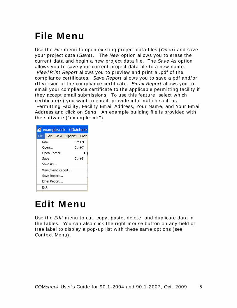
File Menu Use the File menu to open existing project data files (Open) and save your project data (Save). The New option allows you to erase the current data and begin a new project data file. The Save As option allows you to save your current project data file to a new name. View/Print Report allows you to preview and print a .pdf of the compliance certificates. Save Report allows you to save a pdf and/or rtf version of the compliance certificate. Email Report allows you to email your compliance certificate to the applicable permitting facility if they accept email submissions. To use this feature, select which certificate(s) you want to email, provide information such as: Permitting Facility, Facility Email Address, Your Name, and Your Email Address and click on Send. An example building file is provided with the software ("example.cck").
Edit Menu Use the Edit menu to cut, copy, paste, delete, and duplicate data in the tables. You can also click the right mouse button on any field or tree label to display a pop-up list with these same options (see Context Menu).
COMcheck User’s Guide for 90.1-2004 and 90.1-2007, Oct. 2009 5
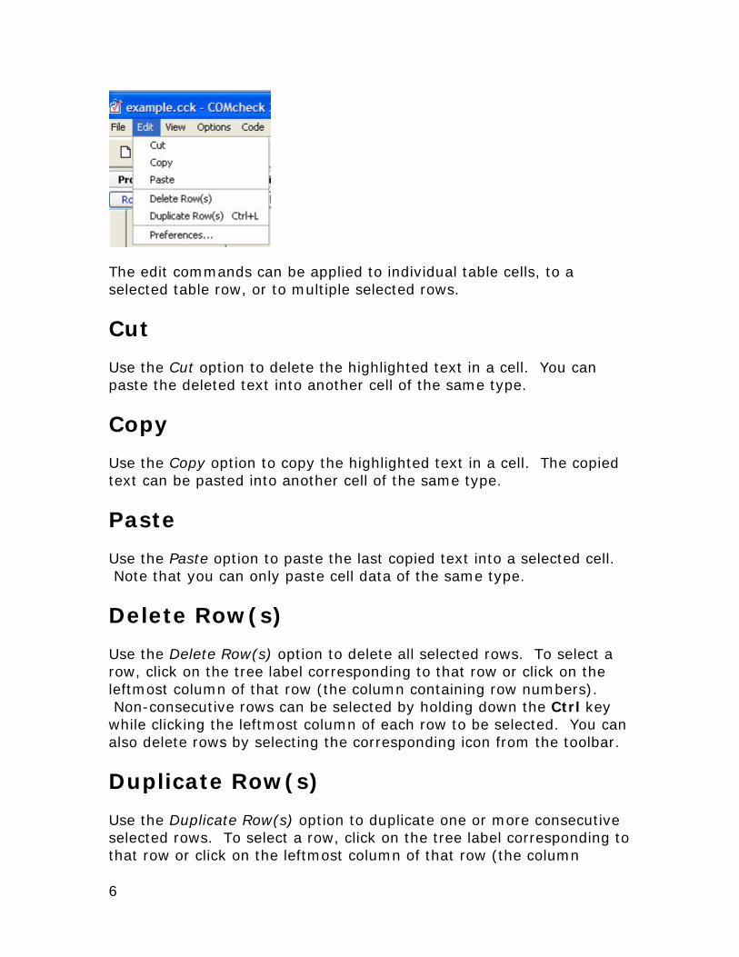
The edit commands can be applied to individual table cells, to a selected table row, or to multiple selected rows.
Cut
Use the Cut option to delete the highlighted text in a cell. You can paste the deleted text into another cell of the same type.
Copy
Use the Copy option to copy the highlighted text in a cell. The copied text can be pasted into another cell of the same type.
Paste
Use the Paste option to paste the last copied text into a selected cell. Note that you can only paste cell data of the same type.
Delete Row(s)
Use the Delete Row(s) option to delete all selected rows. To select a row, click on the tree label corresponding to that row or click on the leftmost column of that row (the column containing row numbers). Non-consecutive rows can be selected by holding down the Ctrl key while clicking the leftmost column of each row to be selected. You can also delete rows by selecting the corresponding icon from the toolbar.
Duplicate Row(s)
Use the Duplicate Row(s) option to duplicate one or more consecutive selected rows. To select a row, click on the tree label corresponding to that row or click on the leftmost column of that row (the column
6
Context Menu
containing row numbers). Non-consecutive rows can be selected by holding down the Ctrl key while clicking the leftmost column of each row to be selected. You can also duplicate rows by selecting the corresponding icon from the toolbar.
Preferences
Use Preferences to set certain software options.
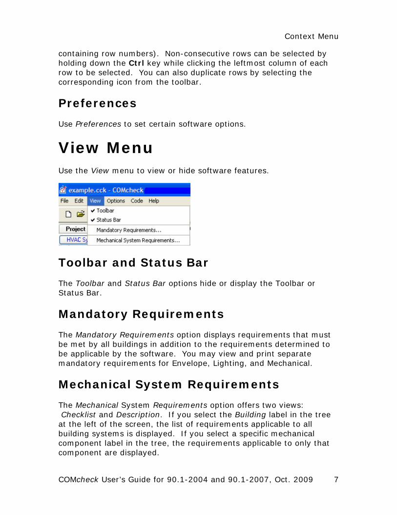
View Menu Use the View menu to view or hide software features.
Toolbar and Status Bar
The Toolbar and Status Bar options hide or display the Toolbar or Status Bar.
Mandatory Requirements
The Mandatory Requirements option displays requirements that must be met by all buildings in addition to the requirements determined to be applicable by the software. You may view and print separate mandatory requirements for Envelope, Lighting, and Mechanical.
Mechanical System Requirements
The Mechanical System Requirements option offers two views: Checklist and Description. If you select the Building label in the tree at the left of the screen, the list of requirements applicable to all building systems is displayed. If you select a specific mechanical component label in the tree, the requirements applicable to only that component are displayed.
COMcheck User’s Guide for 90.1-2004 and 90.1-2007, Oct. 2009 7
The Checklist option displays the same lists of requirements as the Description option but in an abbreviated (checklist) format. The Description option displays a comprehensive description of requirements applicable to the selected component.
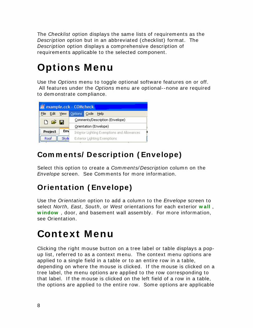
Options Menu Use the Options menu to toggle optional software features on or off. All features under the Options menu are optional--none are required to demonstrate compliance.
Comments/Description (Envelope)
Select this option to create a Comments/Description column on the Envelope screen. See Comments for more information.
Orientation (Envelope)
Use the Orientation option to add a column to the Envelope screen to select North, East, South, or West orientations for each exterior wall , window , door, and basement wall assembly. For more information, see Orientation.
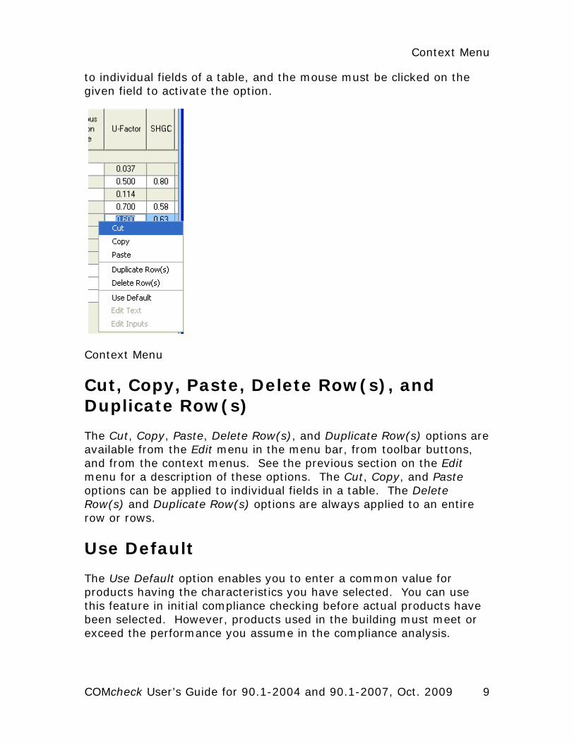
Context Menu Clicking the right mouse button on a tree label or table displays a pop-up list, referred to as a context menu. The context menu options are applied to a single field in a table or to an entire row in a table, depending on where the mouse is clicked. If the mouse is clicked on a tree label, the menu options are applied to the row corresponding to that label. If the mouse is clicked on the left field of a row in a table, the options are applied to the entire row. Some options are applicable
8
Context Menu
to individual fields of a table, and the mouse must be clicked on the given field to activate the option.
Context Menu
Cut, Copy, Paste, Delete Row(s), and Duplicate Row(s)
The Cut, Copy, Paste, Delete Row(s), and Duplicate Row(s) options are available from the Edit menu in the menu bar, from toolbar buttons, and from the context menus. See the previous section on the Edit menu for a description of these options. The Cut, Copy, and Paste options can be applied to individual fields in a table. The Delete Row(s) and Duplicate Row(s) options are always applied to an entire row or rows.
Use Default
The Use Default option enables you to enter a common value for products having the characteristics you have selected. You can use this feature in initial compliance checking before actual products have been selected. However, products used in the building must meet or exceed the performance you assume in the compliance analysis.
COMcheck User’s Guide for 90.1-2004 and 90.1-2007, Oct. 2009 9

10
The Use Default option places a common value into an individual field of a table. For example, after selecting a window component and describing the glazing and frame characteristics of that window, you can right-click the U-Factor column of the window component and select the Use Default option from the Context menu. The software will supply a window U-factor that is "typical" for a window with those characteristics. Select Use Default by right-clicking on the SHGC column and the software will provide a typical solar heat gain coefficient (SHGC) value for the window.
You can also right-click in the Fixture Wattage column on the Lighting screen; then select Use Default to have the software provide a typical fixture input wattage, i.e., for the lamp/ballast combination.
Edit Text
The Edit Text option is used to edit the text on a tree label. When you create a new envelope assembly or lighting fixture, a new row appears in the corresponding table and a new tree label appears on the tree to the left. The tree labels are assigned default names such as Roof 1 or Incandescent 2. These labels can be changed by clicking the right mouse button on the label and selecting Edit Text from the Context menu. An edit box will become visible where the label used to be, and you can rename the label by typing in the edit box. Press Enter or click elsewhere when finished. You can enter a maximum of 128 characters in the edit box. You can also edit tree labels by double-clicking on the label.
Edit Inputs
The Edit Inputs option is only available on the Envelope screen when right-clicking on a basement wall row or a slab row. On the Mechanical screen, if you want to change any of the inputs for a particular mechanical component, click the right mouse button on the tree label for that component and select Edit System Inputs, Edit Plant Inputs, or Edit SWH Inputs (the context menu option changes depending on which type of mechanical component you have selected). The input screen(s) will be redisplayed with your original inputs, which you can change.
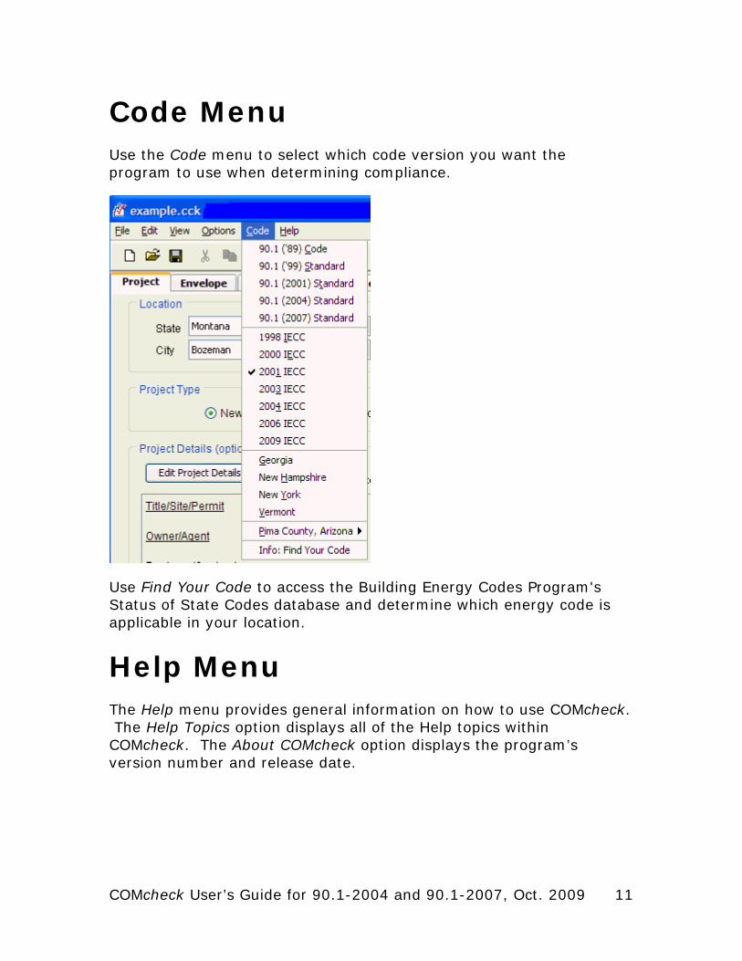
Code Menu Use the Code menu to select which code version you want the program to use when determining compliance.
Use Find Your Code to access the Building Energy Codes Program's Status of State Codes database and determine which energy code is applicable in your location.
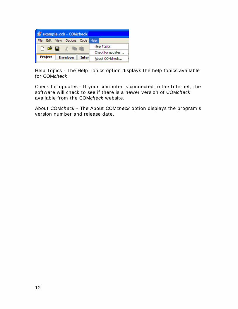
Help Menu The Help menu provides general information on how to use COMcheck. The Help Topics option displays all of the Help topics within COMcheck. The About COMcheck option displays the program’s version number and release date.
COMcheck User’s Guide for 90.1-2004 and 90.1-2007, Oct. 2009 11
12
Help Topics - The Help Topics option displays the help topics available for COMcheck.
Check for updates - If your computer is connected to the Internet, the software will check to see if there is a newer version of COMcheck available from the COMcheck website.
About COMcheck - The About COMcheck option displays the program's version number and release date.
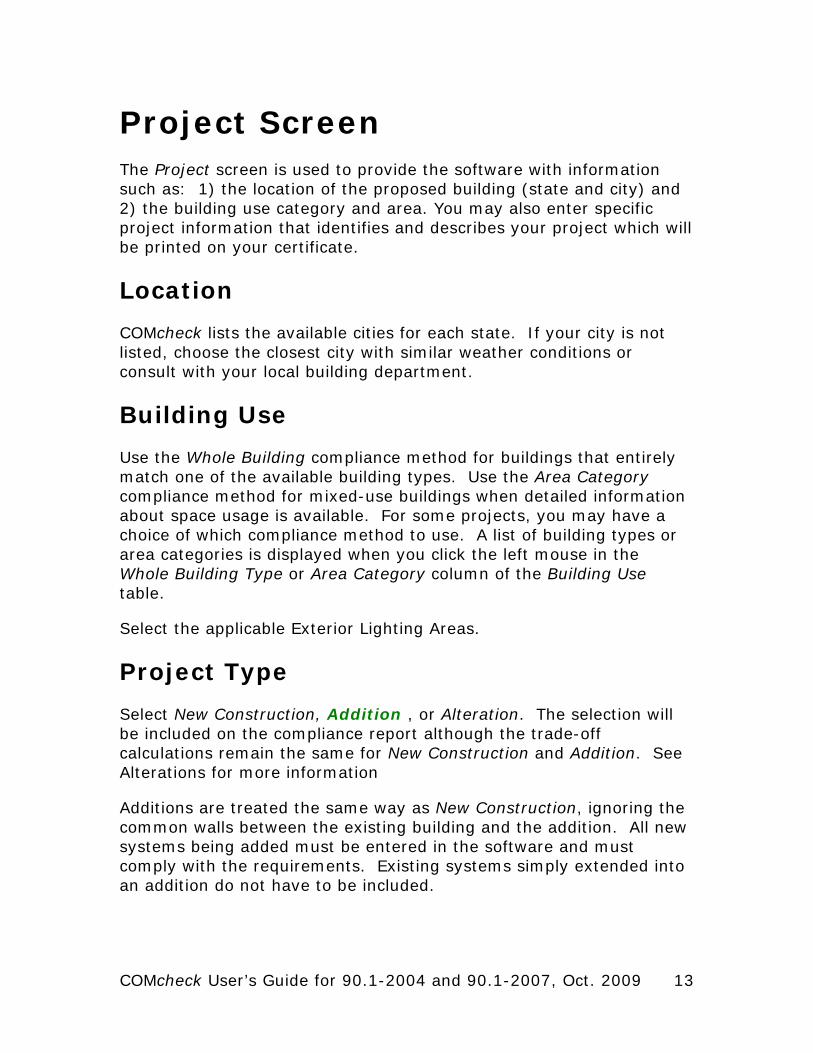
Project Screen The Project screen is used to provide the software with information such as: 1) the location of the proposed building (state and city) and 2) the building use category and area. You may also enter specific project information that identifies and describes your project which will be printed on your certificate.
Location
COMcheck lists the available cities for each state. If your city is not listed, choose the closest city with similar weather conditions or consult with your local building department.
Building Use
Use the Whole Building compliance method for buildings that entirely match one of the available building types. Use the Area Category compliance method for mixed-use buildings when detailed information about space usage is available. For some projects, you may have a choice of which compliance method to use. A list of building types or area categories is displayed when you click the left mouse in the Whole Building Type or Area Category column of the Building Use table.
Select the applicable Exterior Lighting Areas.
Project Type
Select New Construction, Addition , or Alteration. The selection will be included on the compliance report although the trade-off calculations remain the same for New Construction and Addition. See Alterations for more information
Additions are treated the same way as New Construction, ignoring the common walls between the existing building and the addition. All new systems being added must be entered in the software and must comply with the requirements. Existing systems simply extended into an addition do not have to be included.
COMcheck User’s Guide for 90.1-2004 and 90.1-2007, Oct. 2009 13
Semiheated Building Checkbox
The checkbox should only be selected if all spaces are Semiheated and the building has no cooling system.
Only the following building types and space categories can be specified as ”Semiheated”
• Whole Building types: Automotive Facility, Manufacturing Facility, Parking Garage, Warehouse, and Workshop
• Area Categories: Common Space Types: Active and Inactive Storage, Hospital and Healthcare: Active Storage - Hospital, Industrial and Auto Service: Automotive Facility Garage Service/Repair, Detailed Manufacturing, Manufacturing Control Room, Manufacturing Corridor/Transition, Manufacturing Equipment Room, Manufacturing General - High Bay, Manufacturing General - Low Bay, Library and Museum: Museum Active and Inactive Storage, Warehouse and Parking: Fine Material Storage, Medium/Bulky Material Storage, Parking Garage - Attendant Only, Parking Garage - Pedestrian
No mechanical cooling can be specified when the building is designated as ”Semiheated”.
The maximum allowable heating system capacity (listed on the Envelope and Mechanical Compliance Certificates) is determined based on the HDD65 of the location.
Mixed-Use Spaces
Spaces of mixed-use that have separate Semiheated spaces within the building should be not be combined on one report. A separate data file should be completed for each space.
Spaces of mixed use that include Residential and Non-Residential can be combined on one report. The compliance calculations will be based on the higher percentage of square footage of each space and/or the stringency of the code between Residential and Non-Residential.
The following building types and space categories (when applicable for the code selected) are defined as Residential (all other building types and space categories that are not listed below are defined as Non-Residential).
14
Project Screen
COMcheck User’s Guide for 90.1-2004 and 90.1-2007, Oct. 2009 15
• Whole Building types: Dormitory, Hotel, Motel, Multifamily, and Penitentiary
• Area Categories: Confinement Cell, Fire Station Sleeping Quarters, Patient Room, Dormitory Living Quarters, Hotel/Motel Guest Rooms, and Multifamily Living Units
The compliance results based on building type for envelope requirements is shown on the Envelope Compliance Certificate.
Project Details
The Project Details section has input fields entitled Title/Site/Permit, Owner/Agent, and Designer/Contractor. All of the information entered in these fields is included in your project report. None of this information is required by the software program to determine compliance with the code. This information may be useful, however, to the building department or as a way to track and label your reports.

Envelope Screen Use the buttons at the top of the Envelope screen to create a list of building components present in your proposed design. Each component you select is added to the building components displayed on the Envelope screen. For each component, enter appropriate values for all fields with white. These fields may include the assembly type, gross area (or perimeter), cavity R-value, continuous R-value, assembly U-factor, construction details, SHGC, and/or projection factor.
Concrete slab-on-grade components require a perimeter entered in linear feet (ft). All other components require an area entered in square feet (ft2). The cavity R-value input is used for insulation placed between structural members, while the continuous R-value input is used for insulation that is continuous across the structure such as rigid-roof insulation or insulating wall sheathing.
After you have completed the description of each new component, the program automatically updates the compliance results. The results are displayed at the bottom of the screen in the Envelope box. If TBD (to be determined) is displayed in this field, you have not filled in all necessary fields. To determine which data are missing or invalid, look for fields with white-on-red text. In addition to providing inputs for all white-on-red fields, you must select at least one building use type and provide its area on the Project screen before the software can determine compliance.
Roofs
Roofs include portions of the building envelope that are above conditioned space and are horizontal or tilted at less than 60 degrees from horizontal.
Select the Roof button to add a roof component to the description of your design on the Envelope screen. Enter each unique roof assembly as a separate component. You can enter multiple roof elements sharing the same construction as one component with appropriate total area.
COMcheck User’s Guide for 90.1-2004 and 90.1-2007, Oct. 2009 17
Roof Types
• Insulation Entirely Above Deck - a roof with insulation (1) installed above (outside of) the roof structure and (2) continuous (i.e., uninterrupted by framing members); insulation is usually rigid foam or high-density mineral fiber.
• Metal Building, Standing Seam - a metal roof with thermal blocks is attached to the purlins by metal attachment clips and foam is installed on top of the purlins and up against the attachment clips.
• Georgia: Select the purlin spacing
• Metal Building, Screw Down - a metal roof without thermal blocks where the insulation is compressed between the roof deck and the purlins, R-13 is the maximum insulation that can be compressed with screw down roofs.
• Georgia: Select the purlin spacing
• 90.1-2007: Thru Fastened w/o Thermal Spacer Blocks
• Attic Roof with Wood Joists - wood frame roof structures in which insulation is placed between structural roof members; e.g., batt or loose-fill insulation in cathedral ceilings or attic spaces.
• Attic Roof with Steel Joists - metal frame roof structures in which insulation is placed between structural roof members; e.g., steel bar joists or trusses with metal webs having insulation below the roof deck.
• 90.1-2004/2007: High Albedo Roof - roof over conditioned spaces that are cooled (i.e., not semiheated or heated-only) and for roofs with attics, those with unventilated attic spaces. More details.
• Other - roof assemblies that do not fit in one of the above five categories (see Assembly U-Factor under Roof Software Inputs).
18
Envelope Screen
Roof Software Inputs
Gross Area
Enter the gross area of the roof component in the Gross Area field. The gross roof area includes the area of all skylights that penetrate the roof. Skylights are shown below the roof to which they belong on the tree control on the left side of the Envelope screen. To change the linkage of a skylight to a roof assembly, drag the skylight label on the tree to a new roof label and release the mouse. The roof area should be measured along the insulated boundary between conditioned and unconditioned space (e.g., along sloping rafters if the roof insulation follows the slope of the roof).
Cavity Insulation R-Value
Enter the R-value of any insulation to be installed in the cavities between roof structural members. All R-values should be rated R-values for insulation materials only. These values are commonly printed on the materials. The insulating values of other parts of the building assemblies (e.g., ceilings and air films) are already accounted for by the software based on assembly type.
Continuous Insulation R-Value
Enter the R-value of any continuous roof insulation. Continuous insulation is insulation that runs continuously over structural members and is free of significant thermal bridging; one example is rigid foam insulation above the roof deck. All R-values should be rated R-values for insulation materials. The insulating values of other parts of the building assemblies (e.g., ceilings and air films) are already accounted for by the software based on assembly type.
Assembly U-Factor
If you have selected the Other roof type, enter the overall U-factor of the roof assembly, including exterior and interior air films. Do not include the finished ceiling in the U-factor calculation if the space between ceiling and roof structure is used as an HVAC plenum. Building departments may require supporting documentation for assemblies entered using the Other roof category and U-Factor field.
COMcheck User’s Guide for 90.1-2004 and 90.1-2007, Oct. 2009 19
Skylights
Skylights are defined as any transparent or translucent section in a building roof, which include glazing material (glass or plastic), frame, and curb. Glazing having a slope less than 60 degrees from horizontal is considered a skylight, while glazing having a slope greater than 60 degrees from horizontal is considered a window.
Select the Skylight button to add a skylight component to the description of your design on the Envelope screen. Enter each unique skylight assembly as a separate component. You can enter multiple skylight elements having the same characteristics as one component with the appropriate total area.
Skylight Software Inputs
The software prompts you to enter three skylight characteristics each time you create a skylight component–frame type and glazing layers are entered in the Assembly column, and glazing type is entered under the Construction Details column. Specifying these skylight characteristics is helpful for inspection purposes and enables the software to provide typical performance characteristics (i.e., U-factor and SHGC ) for various glazing options.
Gross Area
Enter the area of the entire skylight component in square feet measured parallel to the skylight surface, including both the glazing material and frame. The rough skylight opening provides an acceptable proxy for this skylight area.
Frame Type and Glazing Layers
The frame type and glazing layers are selected from a pop-up list accessed by clicking the left mouse button in the Assembly field. For frame materials not listed, use the frame type that is thermally most similar; e.g., use Wood for metal-clad wood skylights. The glazing layers field enables you to identify the number of glazing layers in the skylight (i.e., single, double, or triple). Low-E coatings are included in the list because the performance impact of low-emissivity films is similar to that of additional glass layers.
20
Envelope Screen
Glazing Type and Curb
The Glazing field (under Construction Details) enables you to identify the type of glass in the skylight (i.e., clear or tinted) and whether or not the skylight has a curb.
U-Factor
Skylight U-factor is based on the entire assembly, including glazing, sash, curbing, and other framing elements. Center-of-glass U-factors cannot be used.
U-factors for skylights must be tested and documented by the manufacturer in accordance with the NFRC test procedure.
The program includes a feature that enables you to insert a typical U-factor for the skylight characteristics you have selected. To access this feature, click the right mouse button on the U-factor input field and select Use Default. The Use Default feature provides values you can use in preliminary evaluations before selecting actual products. However, the actual ratings of products put in place in the building must meet or exceed (i.e., be no higher than) the values you assume in the compliance analysis. Most products on the market will meet or exceed the performance levels provided by the Use Default feature.
Solar Heat Gain Coefficient (SHGC)
The Solar Heat Gain Coefficient (SHGC) field enables you to specify the glazing's effectiveness in rejecting solar heat gain. SHGC is part of a system for rating glazing performance used by the National Fenestration Rating Council (NFRC). SHGC is gradually replacing the older index, shading coefficient (SC), in product literature and design standards. If you are using glass whose performance is listed in terms of SC, you may convert to SHGC by multiplying the SC value by 0.87. Although skylight SHGC is an important variable for energy-efficient design, it is not important in this compliance procedure. Deviations from the program's typical values for skylight SHGC are unlikely to impact compliance.
Exterior Walls
Select the Ext. Wall button to add an exterior above-grade wall to the description of your design on the Envelope screen. Each unique above-grade wall assembly should be entered as a separate
COMcheck User’s Guide for 90.1-2004 and 90.1-2007, Oct. 2009 21
component, but multiple wall elements sharing the same construction and orientation (if used) may be entered as one component with appropriate total area.
Exterior and Interior Wall Types
• Wood-Framed, 16" o.c. - wood frame walls of any stud depth, spaced 16" o.c. The category is intended primarily for lightweight walls but may also be used for walls with masonry veneers.
• Wood-Framed, 24" o.c. - wood frame walls of any stud depth, spaced 24" o.c. The category is intended primarily for lightweight walls but may also be used for walls with masonry veneers.
• Steel-Framed, 16" o.c. - steel frame stud walls of any gauge or depth, spaced 16" o.c. The category is intended primarily for lightweight walls but may also be used for walls with masonry veneers.
• Steel-Framed, 24" o.c. - steel frame stud walls of any gauge or depth, spaced 24" o.c. The category is intended primarily for lightweight walls but may also be used for walls with masonry veneers.
• Metal Building Wall - metal building walls whose structure consists of metal spanning members supported by steel structural members (i.e., does not include spandrel glass or metal panels in curtain wall systems) where wall insulation is draped across metal structural members and metal siding is attached directly to the structural members without rigid insulating spacers.
• Solid Concrete - a wall construction category used with masonry, precast, and poured-in-place solid concrete, and solid concrete masonry units. There are ten wall thicknesses from which to choose.
• Concrete Block - concrete masonry units
• Solid Grouted - concrete masonry units with the cell completely filled with concrete.
• Partially Grouted, Cells Empty - concrete masonry units with at least 50% of the cells free of grout or cells that are
22
Envelope Screen
grouted no more than 32" o.c. vertically and 48" o.c. horizontally.
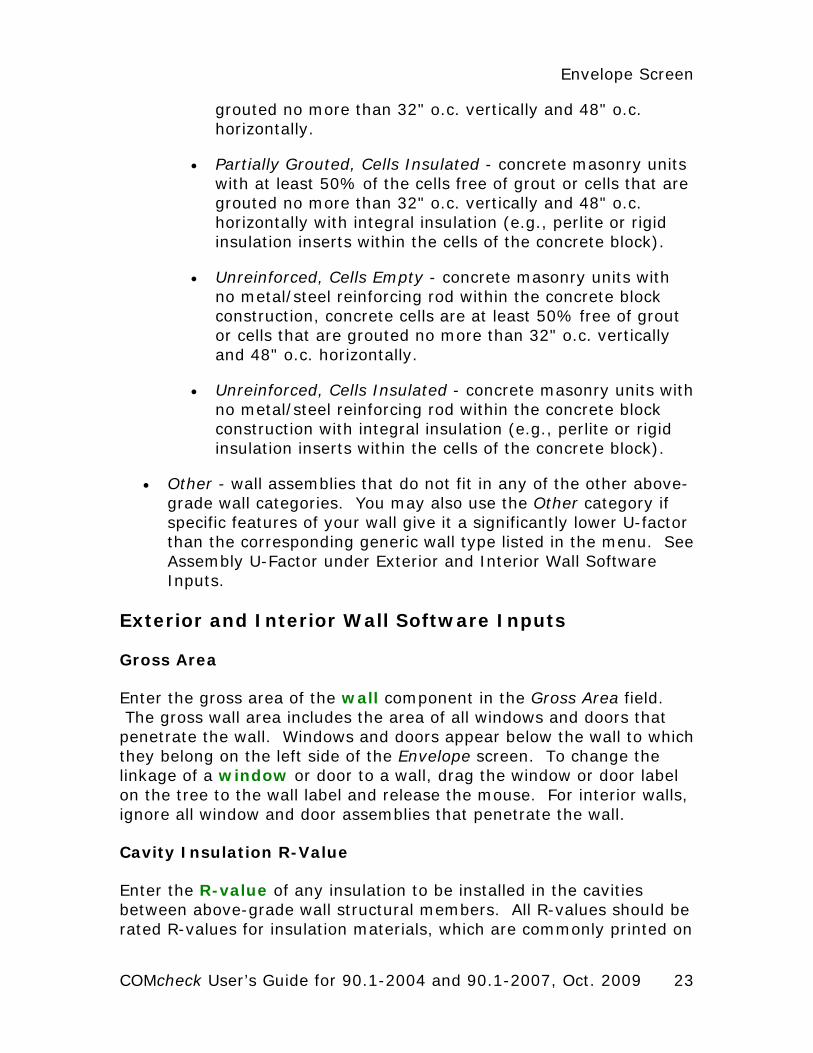
• Partially Grouted, Cells Insulated - concrete masonry units with at least 50% of the cells free of grout or cells that are grouted no more than 32" o.c. vertically and 48" o.c. horizontally with integral insulation (e.g., perlite or rigid insulation inserts within the cells of the concrete block).
• Unreinforced, Cells Empty - concrete masonry units with no metal/steel reinforcing rod within the concrete block construction, concrete cells are at least 50% free of grout or cells that are grouted no more than 32" o.c. vertically and 48" o.c. horizontally.
• Unreinforced, Cells Insulated - concrete masonry units with no metal/steel reinforcing rod within the concrete block construction with integral insulation (e.g., perlite or rigid insulation inserts within the cells of the concrete block).
• Other - wall assemblies that do not fit in any of the other above-grade wall categories. You may also use the Other category if specific features of your wall give it a significantly lower U-factor than the corresponding generic wall type listed in the menu. See Assembly U-Factor under Exterior and Interior Wall Software Inputs.
Exterior and Interior Wall Software Inputs
Gross Area
Enter the gross area of the wall component in the Gross Area field. The gross wall area includes the area of all windows and doors that penetrate the wall. Windows and doors appear below the wall to which they belong on the left side of the Envelope screen. To change the linkage of a window or door to a wall, drag the window or door label on the tree to the wall label and release the mouse. For interior walls, ignore all window and door assemblies that penetrate the wall.
Cavity Insulation R-Value
Enter the R-value of any insulation to be installed in the cavities between above-grade wall structural members. All R-values should be rated R-values for insulation materials, which are commonly printed on
COMcheck User’s Guide for 90.1-2004 and 90.1-2007, Oct. 2009 23
the materials. The insulating values of other parts of the building assemblies (e.g., gypsum board and air films) are already accounted for by the software based on assembly type.
Continuous Insulation R-Value
Enter the R-value of any continuous insulation in the above-grade wall. Continuous insulation is insulation that is continuous over framing members or furring strips and is free of significant thermal bridging. All R-values should be rated R-values for insulation materials. The insulating values of other parts of the building assemblies (e.g., gypsum board and air films) are already accounted for by the software based on assembly type.
Assembly U-Factor
If you have selected the Other wall type option, enter the overall U-factor of the above-grade wall assembly, including exterior and interior air films. Building departments may require supporting documentation for assemblies entered using the Other wall category and U-Factor field.
Concrete Density
If Solid Concrete or Concrete Block is selected, the density of the concrete must also be given. Light Weight is less than 105 lbs/ft3; Medium Weight is 105-124 lbs/ft3; and Normal Weight is greater than or equal to 125 lbs/ft3.
Furring Type
The Furring input field is displayed in the Construction Details column for structural masonry (concrete) above-grade walls. The furring input enables you to specify the type of furring material (if any) used on the wall. If the wall has no furring, select None. If the wall assembly employs metallic furring strips, clips, or framing members, select Metal; otherwise, select Wood.
The furring material is assumed to create some thermal bridging of the insulation in the cavity between furring members, thereby reducing insulation effectiveness.
24
Envelope Screen
Heat Capacity
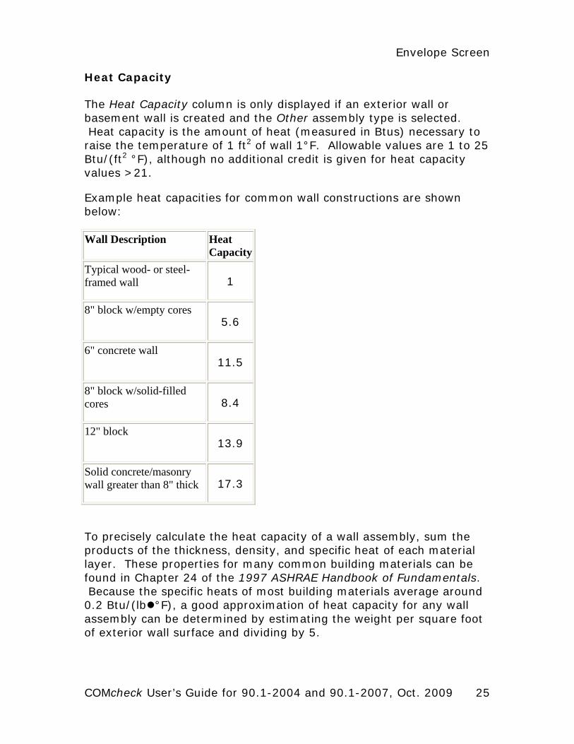
The Heat Capacity column is only displayed if an exterior wall or basement wall is created and the Other assembly type is selected. Heat capacity is the amount of heat (measured in Btus) necessary to raise the temperature of 1 ft2 of wall 1°F. Allowable values are 1 to 25 Btu/(ft2 °F), although no additional credit is given for heat capacity values >21.
Example heat capacities for common wall constructions are shown below:
Wall Description Heat Capacity
Typical wood- or steel-framed wall 1
8" block w/empty cores 5.6
6" concrete wall 11.5
8" block w/solid-filled cores 8.4
12" block 13.9
Solid concrete/masonry wall greater than 8" thick 17.3
To precisely calculate the heat capacity of a wall assembly, sum the products of the thickness, density, and specific heat of each material layer. These properties for many common building materials can be found in Chapter 24 of the 1997 ASHRAE Handbook of Fundamentals. Because the specific heats of most building materials average around 0.2 Btu/(lb °F), a good approximation of heat capacity for any wall assembly can be determined by estimating the weight per square foot of exterior wall surface and dividing by 5.
COMcheck User’s Guide for 90.1-2004 and 90.1-2007, Oct. 2009 25
All of the software compliance calculations assume that any insulation in an above-grade exterior wall (or above-grade portion of a below-grade wall assembly) is integral with the thermal mass of the wall, as opposed to assuming the insulation is either on the exterior or the interior of the wall. This fixed assumption provides the most generous assessment of the benefits of high heat-capacity walls that would have been available had the program included an insulation position input.
Entering Assemblies by Orientation
The software allows you to enter building components with or without considering the component orientation (north, south, east, and west). Initially, the orientation option is turned off. If you prefer to enter components based on their orientation, select the Orientation option under the Options menu. The compliance calculation will not be based on orientation-specific components until an orientation has been assigned to each exterior wall, window, door, and basement wall component.
If the orientation feature is not being used, you can group and list like components as a single component. However, if you need more than one entry of the same component (e.g. where two assemblies of the same type have different insulation levels), you must create as many additional components as required.
Interior Semi-Exterior Walls
Select the Int. Wall (Int. Wall is the same as semi-exterior wall in the 90.1-1999, 90.1-2004 and 90.1-2007 Standards) button to add an interior above-grade wall to the description of your design on the Envelope screen. Enter only interior walls separating conditioned from unconditioned space; ignore all other interior walls. Wall types for interior walls are the same as the wall types for exterior walls. The software inputs are also the same.
Windows
Windows are defined as any transparent or translucent section in an exterior building wall, including sliding-glass doors, patio doors, and glass blocks but excluding glass entry doors (which are entered using the Door button). Windows include glazing material (which may be glass or plastic), framing (mullions, muntins, and dividers), external shading devices, internal shading devices, and integral (between
26
Envelope Screen
glass) shading devices. Glazing having a slope greater than 60 degrees from horizontal is considered a window, while glazing having a slope less than 60 degrees from horizontal is considered a skylight.
Select the Window button to add a window component to the description of your design on the Envelope screen. Enter each unique window assembly as a separate component. You can enter multiple window elements having the same characteristics as one component with an appropriate total area.
Window Software Inputs
The software prompts you to enter four window characteristics each time you create a window component-frame type and glazing layers are entered in the Assembly column, and glazing type and operability are entered under the Construction Details column. Specifying these window characteristics is helpful for inspection purposes and enables the software to provide typical performance characteristics (i.e., U-factor , SHGC ) for various glazing options.
If doors have more than 50% glazing, they should be entered as windows.
Gross Area
Enter the area of the entire window component in square feet (ft2) measured parallel to the window surface, including both glazed materials and frame. The rough window opening provides an acceptable proxy for this window area.
Frame Type and Glazing Layers
The frame type and glazing layers are selected from a pop-up list accessed by clicking the left mouse button in the Assembly field. The frame type enables you to identify the window frame material and hence characterize the thermal conductivity of the frame. For frame materials not listed, use the frame type that is thermally most similar; e.g., use Wood for metal-clad wood windows. The glazing layers enables you to identify the number of glazing layers in the windows (i.e., single, double, or triple). Low-E coatings are included in the list because the performance impact of low-emissivity films is similar to that of additional glass layers.
COMcheck User’s Guide for 90.1-2004 and 90.1-2007, Oct. 2009 27
Glazing Type and Operability
The Glazing field (under Construction Details) enables you to identify the type of glass in the window (i.e., clear or tinted). 90.1-2004: Operable includes casements, double-hung, single-hung, sliders, hoppers, awnings, and other window configurations that have at least some sash that is operable. Fixed includes windows that do not open.
U-Factor
Window U-factor is based on the entire assembly, including both glazing and frame. Center-of-glass U-factors cannot be used. Glazing U-factors must be tested and documented by the manufacturer in accordance with the National Fenestration Rating Council (NFRC) test procedure. The software includes a feature that enables you to insert a typical U-factor for the window characteristics you have selected. To access this feature, click the right mouse button on the U-factor input field and select Use Default. The Use Default feature provides values you can use in preliminary evaluations before selecting actual products. However, the actual ratings of products in the building must meet or exceed (i.e., be no higher than) the values you assume in the compliance analysis. Most products on the market will meet or exceed the performance levels provided by the Use Default feature.
Solar Heat Gain Coefficient
The Solar Heat Gain Coefficient (SHGC) specifies the glazing's effectiveness in rejecting solar heat gain. SHGC is part of a system for rating window performance used by the NFRC. SHGC is gradually replacing the older index, shading coefficient (SC), in product literature and design standards. If you are using glass whose performance is listed in terms of SC, you may convert to SHGC by multiplying the SC value by 0.87.
SHGCs must be tested and documented by the manufacturer in accordance with the NFRC test procedure.
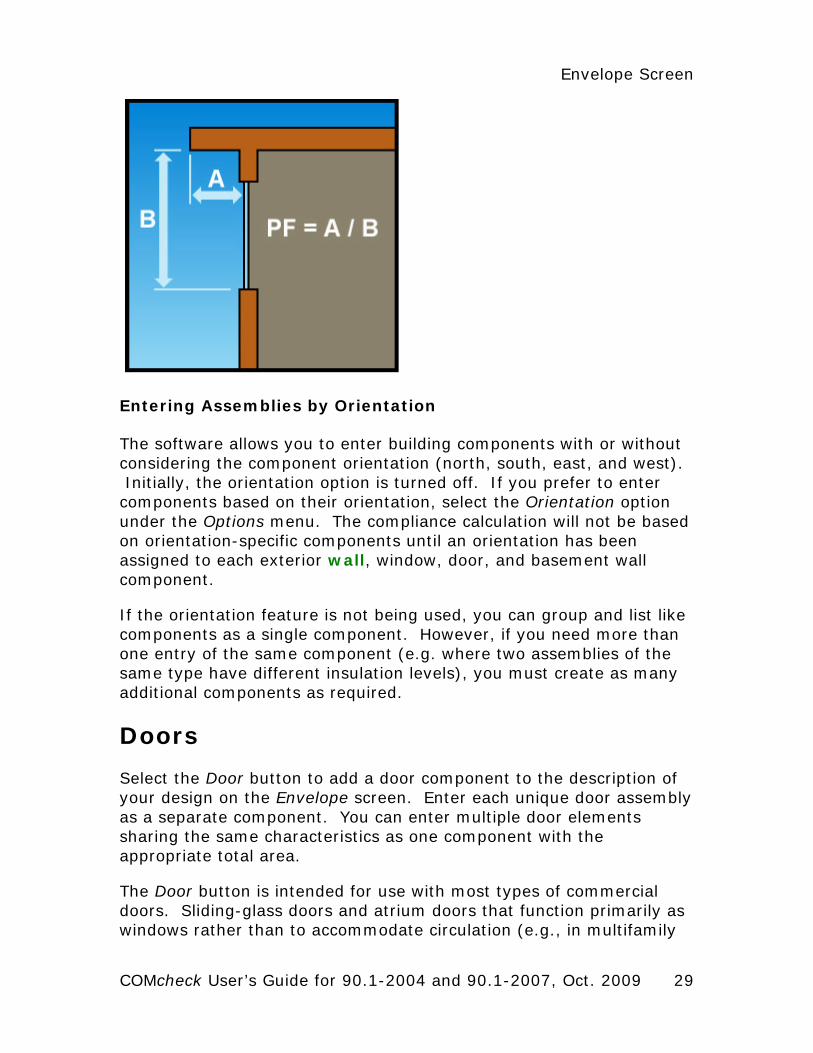
Projection Factor
The projection factor enables you to characterize the shading impact of horizontal overhangs or canopies that project outward from the plane of the window. The projection factor is the ratio of the distance the overhang projects from the window surface to its height above the sill of the window it shades.
28
Envelope Screen
Entering Assemblies by Orientation
The software allows you to enter building components with or without considering the component orientation (north, south, east, and west). Initially, the orientation option is turned off. If you prefer to enter components based on their orientation, select the Orientation option under the Options menu. The compliance calculation will not be based on orientation-specific components until an orientation has been assigned to each exterior wall, window, door, and basement wall component.
If the orientation feature is not being used, you can group and list like components as a single component. However, if you need more than one entry of the same component (e.g. where two assemblies of the same type have different insulation levels), you must create as many additional components as required.
Doors
Select the Door button to add a door component to the description of your design on the Envelope screen. Enter each unique door assembly as a separate component. You can enter multiple door elements sharing the same characteristics as one component with the appropriate total area.
The Door button is intended for use with most types of commercial doors. Sliding-glass doors and atrium doors that function primarily as windows rather than to accommodate circulation (e.g., in multifamily
COMcheck User’s Guide for 90.1-2004 and 90.1-2007, Oct. 2009 29
or hotel/motel) should be entered using the Window button and not the Door button. Doors located in exterior walls and the walls of conditioned basements should be included, but areas of doors separating conditioned from unconditioned space should be included in the areas of the interior walls which they penetrate.
Door Types
• Uninsulated Single-Layer Metal - swinging or non-swinging doors, including single-layer uninsulated access hatches and uninsulated smoke vents.
• Uninsulated Double-Layer Metal - swinging or non-swinging doors, including double-layer uninsulated access hatches and uninsulated smoke vents.
• Insulated Metal - swinging or non-swinging doors, including fire-rated doors, insulated access hatches, and insulated smoke vents.
• Wood - minimum nominal thickness of 1 ¾ in., including panel doors with minimum panel thickness of 1 1/8 in., solid core flush doors, and hollow core flush doors.
• Glass (>50% glazing) - exterior doors that are mostly glazed (i.e., glass covers more than half of the door's area) and are intended to accommodate occupant circulation. Note: even though entered as a door, the software treats the glass door like a window (per Standard 90.1-1999).
• Other - any exterior doors that do not fit in any of the other four door categories. You must enter a U-factor and you should be prepared to provide the building department with manufacturers' literature or documentation of U-factor calculations.
Door Software Inputs
If doors have more than 50% glazing, they should be entered as windows.
30
Envelope Screen
Gross Area
Enter the total area of the door in square feet, including any glazed portions. The rough opening for the door is an acceptable proxy for this door area.
Construction Details
Non-swinging doors - roll-up, sliding, and all other doors that are not swinging doors.
Swinging doors - all operable solid panels with hinges on one side and solid revolving doors.
U-Factor
Enter the overall U-factor for the door(s) from manufacturers' literature. You may select the Use Default option from the pop-up context menu accessed by clicking the right mouse button in the U-Factor field. The Use Default option provides a U-factor for a door judged typical of the selected type containing little or no thermal insulation.
Entering Assemblies by Orientation
The software allows you to enter building components with or without considering the component orientation (north, south, east, and west). Initially, the orientation option is turned off. If you prefer to enter components based on their orientation, select the Orientation option under the Options menu. The compliance calculation will not be based on orientation-specific components until an orientation has been assigned to each exterior wall, window, door, and basement wall component.
If the orientation feature is not being used, you can group and list like components as a single component. However, if you need more than one entry of the same component (e.g. where two assemblies of the same type have different insulation levels), you must create as many additional components as required.
Basement Walls
The basement wall component is intended for use with walls that are either partially or fully below grade. Ignore portions of basement walls
COMcheck User’s Guide for 90.1-2004 and 90.1-2007, Oct. 2009 31
more than 10 ft below grade. The software automatically treats above-grade portions of basement wall components like above-grade exterior walls.
Select the Basement button to add a basement wall component to the description of your design on the Envelope screen. Enter each unique basement wall assembly as a separate component. You can enter multiple basement wall elements sharing the same construction as one component with the appropriate total area.
Basement Wall Types
• Solid Concrete - a wall construction category used with masonry, precast, and poured-in-place solid concrete, and solid concrete masonry units. There are ten wall thicknesses from which to choose.
• Concrete Block - concrete masonry units
• Solid Grouted - concrete masonry units with the cell completely filled with concrete.
• Partially Grouted, Cells Empty - concrete masonry units with at least 50% of the cells free of grout or cells that are grouted no more than 32" o.c. vertically and 48" o.c. horizontally.
• Partially Grouted, Cells Insulated - concrete masonry units with at least 50% of the cells free of grout or cells that are grouted no more than 32" o.c. vertically and 48" o.c. horizontally with integral insulation (e.g., perlite or rigid insulation inserts within the cells of the concrete block).
• Unreinforced, Cells Empty - concrete masonry units with no metal/steel reinforcing rod within the concrete block construction, concrete cells are at least 50% free of grout or cells that are grouted no more than 32" o.c. vertically and 48" o.c. horizontally.
• Unreinforced, Cells Insulated - concrete masonry units with no metal/steel reinforcing rod within the concrete block construction with integral insulation (e.g., perlite or rigid insulation inserts within the cells of the concrete block).
32
Envelope Screen
• Other - wall assemblies that do not fit in any of the other above-grade wall categories. You may also use the Other category if specific features of your wall give it a significantly lower U-factor than the corresponding generic wall type listed in the menu. See Assembly U-Factor under Exterior and Interior Wall Software Inputs.
Basement Wall Software Inputs
Gross Area
Enter the gross area of the basement wall component in the Gross Area or Perimeter column. The gross wall area includes the area of both above-grade and below-grade portions of the basement wall, and all windows and doors that penetrate the wall. Windows and doors appear below the wall to which they belong on the tree on the left side of the Envelope screen. To change the linkage of a window or door to a basement wall, drag the window or door label on the tree to the wall label and release the mouse.
Windows and Doors in Basement Walls
When windows and doors are added to basement walls, net opaque wall areas are determined by subtracting windows and doors from any above-grade part of the basement wall. If necessary, the above-grade portion of the basement wall is increased so that windows and doors belong to the above-grade part of the basement wall. See Wall Height and Depth Below Grade Help topics for an explanation of how basement walls are treated with respect to being above or below grade.
Cavity Insulation R-Value
Enter the R-value of any insulation to be installed in the cavities between furring strips. All R-values should be rated R-values for insulation materials, which are commonly printed on the materials. The insulating values of other parts of the building assemblies (e.g., masonry and air films) are already accounted for by the software based on assembly type.
Continuous Insulation R-Value
Enter the R-value of any continuous insulation to be installed either on the inside or the outside of the basement wall. Continuous
COMcheck User’s Guide for 90.1-2004 and 90.1-2007, Oct. 2009 33
insulation is insulation that runs continuously and is free of significant thermal bridging. All R-values should be rated R-values for insulation materials. The insulating values of other parts of the building assemblies (e.g., masonry and air films) are already accounted for by the software based on assembly type.
Assembly U-Factor
If you have selected the Other basement wall type option, you must enter the overall U-factor of the basement wall assembly, including the interior air film but excluding the effects of earth and exterior air films. Building departments may require supporting documentation for assemblies entered using the Other basement wall category and U-Factor field.
Concrete Density
If Solid Concrete or Concrete Block is selected, the density of the concrete must also be given. Light Weight is less than 105 lbs/ft3; Medium Weight is 105-124 lbs/ft3; and Normal Weight is greater than or equal to 125 lbs/ft3.
Wall Height
Enter the average height of the basement wall measured from the top of the basement floor to the top of the basement wall.
The Wall Height (ft) and Depth Below Grade (ft) fields together enable you to enter a basement wall assembly partially above and partially below grade as a single entry. If the values in these two fields are the same, the wall will be treated as entirely below grade.
Depth Below Grade
Enter the average depth below grade of the wall in the Depth Below Grade (ft) field, measuring from the average grade level to the top of the basement floor.
Furring Type
The Furring input field (under Construction Details) enables you to specify the type of furring material (if any) used on the wall. If the wall has no furring, select None. If the wall assembly employs metallic
34
Envelope Screen
furring strips, clips, or framing members, select Metal; otherwise, select Wood.
The furring material is assumed to create some thermal bridging of the insulation in the cavity between furring members, thereby reducing insulation effectiveness.
Entering Assemblies by Orientation
The software allows you to enter building components with or without considering the component orientation (north, south, east, and west). Initially, the orientation option is turned off. If you prefer to enter components based on their orientation, select the Orientation option under the Options menu. The compliance calculation will not be based on orientation-specific components until an orientation has been assigned to each exterior wall, window, door, and basement wall component.
If the orientation feature is not being used, you can group and list like components as a single component. However, if you need more than one entry of the same component (e.g. where two assemblies of the same type have different insulation levels), you must create as many additional components as required.
Floors
Select the Floor button to add a floor component to the description of your design on the Envelope screen. Enter each unique exposed floor assembly as a separate component. You can enter multiple floor elements sharing the same construction as one component with the appropriate total area.
The Floor button is used to enter floors over unconditioned space, including floors exposed to exterior conditions, floors over crawl spaces, floors over unconditioned parking garages, and slab-on-grade floors. Interior floors that do not separate conditioned from unconditioned space are not included. Ignore slabs more than 2 ft. below grade.
Floor Types
• Concrete Floor (over unconditioned space) - a poured-in-place concrete floor over unconditioned space (e.g., concrete floor over an unconditioned parking garage).
COMcheck User’s Guide for 90.1-2004 and 90.1-2007, Oct. 2009 35
• Steel Joist - a floor that is not a concrete floor and that has steel joist members supported by structural members.
• Wood-Framed - a floor that has wood joists in which insulation is placed between structural members (e.g., batt insulation between wood floor joists).
• Slab-On-Grade - that portion of a slab floor of a building envelope that is in contact with the ground and that is either above grade or is less than or equal to 24 in. below the final elevation of the nearest exterior grade.
• Heated - slab-on-grade floor with a heating source either within or below it
• Unheated - slab-on-grade floor that is not heated
• Other - floor assemblies that do not fit in one of the above categories.
Floor Software Inputs
Gross Area or Slab Perimeter
Enter the gross area of the floor (in square feet) along the boundary where it separates conditioned from unconditioned space or enter the perimeter of the slab-on-grade component in linear feet.
Cavity Insulation R-Value
Enter the R-value of any insulation to be installed in the cavities between floor structural members. All R-values should be rated R-values for insulation materials, which are commonly printed on the materials. The insulating values of other parts of the building assemblies (e.g., subfloor and air films) are already accounted for by the software.
Continuous Insulation R-Value
Enter the R-value of any continuous floor insulation. Continuous insulation is insulation that runs continuously over structural members and is free of significant thermal bridging. All R-values should be rated R-values for insulation materials. The insulating values of other parts of the building assemblies (e.g., subfloor and air films) are
36
Envelope Screen
already accounted for by the software. For slabs, enter the R-value of the slab perimeter insulation.
Assembly U-Factor
If you have selected the Other floor type option, you must enter the overall U-factor of the floor assembly, including exterior and interior air films. Building departments may require supporting documentation for assemblies entered using the Other floor category and U-Factor field.
Slab Type
The slab type is selected from a pop-up list accessed by clicking the left mouse button in the Assembly field. The slab type enables you to specify whether the concrete slab is heated or unheated. A heated slab (e.g., radiant slab) is one designed as part of a space-conditioning system for transmitting heating into the space. Heated slabs have higher insulation requirements than unheated slabs under the code.
Insulation Position and Depth for Slab-On-Grade
The insulation position pop-up list enables you to specify if perimeter slab insulation will be used and, if so, if it will be placed vertically or horizontally. If no perimeter insulation will be used, select No Insulation.
The Insulation field (under Construction Details) enables you to specify the depth of the insulation. The insulation must extend downward from the top of the slab, or downward to at least the bottom of the slab and then horizontally to the interior or exterior. Where slab insulation is required, it must fully insulate the slab edge and extend from the top of the slab to the depth you select.
Horizontal with Vertical Slab Insulation Option: Horizontal insulation extending away from the foundation must be covered by pavement or at least 10 in. of soil. If placed horizontally with vertical insulation, insulation depth is the vertical distance from the top of the slab downward to the bottom slab, and then horizontally underneath the slab. Five options are available for horizontal plus vertical insulation depth: 1', 2', 3', 4', and Fully Insulated. Select Fully Insulated if the insulation runs vertically and then horizontally under the entire slab.
COMcheck User’s Guide for 90.1-2004 and 90.1-2007, Oct. 2009 37
38
Horizontal without Vertical Slab Insulation Option: If placed horizontally, insulation depth is the total horizontal distance underneath the slab. Four options are available for horizontal insulation depth: 1', 2', 3', >=4'.
Vertical Insulation Option: Insulation that is placed vertically, insulation depth is measured from the top of the slab downward. Four options are available for vertical insulation depth: 1', 2', 3', and 4'.
Comments
Select the Comments/Description (Envelope) option to create a Comments/Description column on the Envelope screen. Use the Comments/Description column to type additional information about a building assembly that you wish to be included in the Inspection Checklist, such as its location. The blank Comment lines provided in the Inspection Checklist are replaced with any text entered in this column.
Orientation
Use the Orientation option to add a column to the Envelope screen to select North, East, South, or West orientations for each exterior wall, window, door, and basement wall assembly. If an orientation is selected for an assembly linked to other assemblies (such as a window linked to an exterior wall), the orientation for all of the linked assemblies is changed to match the new selection.
If an orientation has been assigned to each wall, window, door, and below-grade wall assembly, the compliance calculation will be based on a proposed building using those orientations. This result may be slightly different than the result obtained when orientation is not specified. In the latter case, assemblies are assumed to be equally distributed according to a code-specified aspect ratio. The orientation-specific compliance calculation will not be performed until all assemblies have been assigned an orientation.
Lighting Screen Use the buttons at the top of the screen to create a list of lighting fixtures present in your proposed design. Each fixture type you select is added to the lighting fixtures list displayed on the screen. For each fixture type, you must enter a ballast type (if applicable), the number of lamps per fixture, quantity, and the fixture input wattage. Input wattage is the electrical power input to the lamp and ballast combination.
After entering complete information for each new fixture, the software automatically updates the compliance results once you hit the Enter key or click in another cell. The results are displayed at the bottom of the screen in the compliance box. If TBD (to be determined) is displayed in this field, you most likely have not yet filled in the fixture wattage or quantity for one or more components. To determine which data are missing or invalid, look for fields with white-on-red text. In addition to providing inputs for all white-on-red fields, you must select at least one building use type and its corresponding area on the Project screen before the software can determine compliance.
Optional features available on the Lighting screens may be selected from the Options menu: Interior Lighting Exemptions and Allowances and Exterior Lighting Exemptions.
Linear Fluorescent
Select the Linear Fluorescent button to add fixtures using T5, T8, T10, or T12 tubes to your list of fixtures on the screen.
Because of space limitations, lighting types are shown on the menus and main screen using abbreviations. For example, 48” T12 ES 34W stands for a fixture using 48” T-12 energy-saving fluorescent lamps rated at 34 watts each. The following abbreviations are used in these descriptions:
• ES - energy saving, a designation that usually indicates the lamp will draw 10% to 15% less power than a standard lamp of the same type
• Slim - slimline, a type of fluorescent lamp that uses single-pin contacts rather than the normal two-pin contacts
COMcheck User’s Guide for 90.1-2004 and 90.1-2007, Oct. 2009 39
• T5 - a designation for tubular fluorescent lamps that are under 1" in diameter
• T8 - a designation for tubular fluorescent lamps that are 1” in diameter
• T10 - a designation for tubular fluorescent lamps that are 1-1/4" in diameter
• T12 - a designation for tubular fluorescent lamps that are 1-1/2” in diameter
• U - U-shaped lamps
• W - nominal lamp wattage. Note that this is not the fixture wattage that is entered in the Fixture Wattage field. The fixture wattage must include ballast energy and will generally be higher than this value.
Compact Fluorescent
Select the Compact Fluorescent button to add compact fluorescent fixtures to your list of fixtures on the screen.
Because of space limitations, lighting types are shown on the menus and main screen using abbreviations. For example, Twin Tube 13W stands for a fixture using compact fluorescent lamps rated at 13 watts each. The following abbreviations are used in the descriptions:
• Twin, Triple, Quad - designation referring to the number of fluorescent tubes projecting from the lamp (i.e., two, three, or four)
• 2-pin, 4-pin - designation referring to the number of contacts at the base of the lamp
• W - nominal lamp wattage. Note that this is not the fixture wattage that is entered in the Fixture Wattage field. The fixture wattage must include ballast energy and will generally be higher than this value.
40
Lighting Screen
HID
Select the HID button to add fixtures using high-intensity discharge (HID) lamps to your list of fixtures on the screen. The following abbreviation is used in the descriptions:
• W - nominal lamp wattage. Note that this is not the fixture wattage that is entered in the Fixture Wattage field. The fixture wattage must include ballast energy and will generally be higher than this value.
Incandescent
Select the Incandescent button to add fixtures using incandescent lamps to your list of fixtures on the screen.
Halogen
Select the Halogen button to add halogen fixtures to your list. Because of space limitations, lighting types are shown on the menus and main screen using abbreviations. For example, Halogen MR-11 20W stands for a fixture using halogen lamps rated at 20 watts each. The following abbreviations are used in the descriptions:
• MR - multifaceted reflector.
Lighting Screen Inputs
Fixture ID
The Fixture ID field shows the fixture ID you have entered. You can associate the fixture with a fixture type designation used on the lighting fixture schedule and elsewhere in the construction documents; e.g., F1 for fixture type 1. Fixture ID is an optional field that you may leave blank, but it is recommended as it enables fixtures to be clearly defined.
Fixture Description
The Fixture Description field is for descriptions of fixtures that you enter. Fixture Description is an optional field that you may leave blank. However, fixture descriptions can help you keep track of the
COMcheck User’s Guide for 90.1-2004 and 90.1-2007, Oct. 2009 41
fixtures in the list, avoid errors and oversights, and facilitate plan review and inspections because this information is included on the compliance certificate. Fixture descriptions may include manufacturer and part number, dimensions (e.g., 2x4), mounting type (e.g., recessed, surface, suspended), or other distinguishing characteristics.
Lamp Description/Wattage Per Lamp
Click the left mouse button in the Lamp Description/Wattage Per Lamp field to select from a drop-down list of available lamp types. The drop-down list contains the most commonly used lamp and ballast combinations. Select Other if the lamp type you intend to use does not match one of the listed types. The Lamp Description/Wattage Per Lamp is not a user-editable field unless you have selected Other from the drop-down list.
Ballast
The ballast type is entered by selecting from a drop-down list. (Incandescent and halogen fixtures do not require a ballast entry.) Available ballast types are magnetic, electronic, premium efficiency, standard, and pulse start. The following definitions have been used in determining default input wattages. You should use these definitions in describing the ballast type in the fixtures you intend to use.
• Magnetic - applies to CFL and linear fluorescent; the standard CFL or linear fluorescent ballast that incorporates large inductive components and operates around 60 Hz.
• Electronic - applies to CFL and linear fluorescent; a CFL or linear fluorescent ballast comprised of electronic and semiconductor components with only very small inductive components that operates at high frequencies in the 20-40 Hz range.
• Premium Efficiency - applies to 4 foot T8 linear fluorescent; a linear 4-foot T8 instant-start, programmed-start, or dimmable NEMA BL2 rated high frequency electronic ballast that exhibits high efficiency in the 88-96 lumen/watt range.
• Standard - applies to all HID; a standard High Intensity Discharge (HID) ballast not incorporating Pulse-start technology.
42
Lighting Screen
COMcheck User’s Guide for 90.1-2004 and 90.1-2007, Oct. 2009 43
• Pulse Start - applies to MH and CMH; a ballast that uses an igniter in place of an additional probe for starting an MH or CMH lamp.
Lamps Per Fixture
Enter the number of lamps per fixture.
Number of Fixtures
Enter the number of fixtures.
Fixture Wattage
You can enter the fixture wattage directly or have the software provide a typical wattage for that fixture. To input a typical wattage, click in the cell and then click the right mouse button in the Fixture Wattage field to display the pop-up context menu. The software will provide a typical input wattage for the fixture. Not all possible lamp and ballast combinations are included-only those for which adequate data were available. If the Use Default option is gray, a typical wattage is not available. Input wattage is the related electrical power input to the lamp and ballast combination.
You may either use the typical input wattage provided by the software or override it with a value based on the equipment you intend to install. In either case, you should be prepared to provide supporting documentation based on manufacturer's literature to the building department.

Mechanical Screen Use the buttons at the top of the Mechanical screen to enter characteristics of HVAC system, plant, and water heating components in your proposed design. Because most requirements in the mechanical section of the energy code are mandatory, the Mechanical section of the software works somewhat differently from the Envelope and Lighting sections. Rather than generating a numerical compliance index, the Mechanical section generates a customized list of mandatory requirements applicable to the mechanical components you identify. Click the Plant button or Water Heating button to enter information about these components. Click the HVAC System button to enter information about your building’s HVAC components.
The software supplies a default component name, along with a corresponding quantity and description for the component you defined. You can edit the default component description or quantity by simply clicking on the appropriate field and typing a new description or quantity. For clarity and consistency with building plans, it may also be helpful to edit the tree labels in the left-hand screen. To change these default names, double-click on the name in the left-hand screen to bring up an edit box for the text.
Alternatively, you can right-click on the name to display a pop-up list (called a context menu) and select Edit Text from this menu. Selecting Edit System Inputs, Edit Plant Inputs, or Edit SWH Inputs from the context menu enables you to redisplay the input screens for the given component and to redefine the component inputs. You may also delete (cut), copy and paste, or duplicate components by selecting the corresponding option from the context menu. For more information on context menus, refer to the Help section Context Menu.
Viewing Mechanical Requirements
To view the requirements that apply to a mechanical component, select the component, then go to the View menu and click the Mechanical System Requirements option. The Description option displays a comprehensive description of requirements applicable to the selected component. The Checklist option displays the same requirements, but in an abbreviated (checklist) format. You can use the View menu to toggle the display back to the list of mechanical
COMcheck User’s Guide for 90.1-2004 and 90.1-2007, Oct. 2009 45
components or to the detailed or concise list of requirements. The output certificate will contain all three views: the list of your selected mechanical components, the checklist of requirements, and the more detailed description of these same requirements.
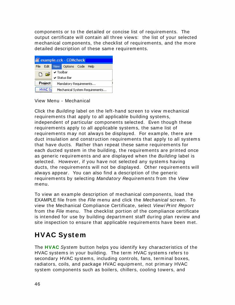
View Menu - Mechanical
Click the Building label on the left-hand screen to view mechanical requirements that apply to all applicable building systems, independent of particular components selected. Even though these requirements apply to all applicable systems, the same list of requirements may not always be displayed. For example, there are duct insulation and construction requirements that apply to all systems that have ducts. Rather than repeat these same requirements for each ducted system in the building, the requirements are printed once as generic requirements and are displayed when the Building label is selected. However, if you have not selected any systems having ducts, the requirements will not be displayed. Other requirements will always appear. You can also find a description of the generic requirements by selecting Mandatory Requirements from the View menu.
To view an example description of mechanical components, load the EXAMPLE file from the File menu and click the Mechanical screen. To view the Mechanical Compliance Certificate, select View/Print Report from the File menu. The checklist portion of the compliance certificate is intended for use by building department staff during plan review and site inspection to ensure that applicable requirements have been met.
HVAC System
The HVAC System button helps you identify key characteristics of the HVAC systems in your building. The term HVAC systems refers to secondary HVAC systems, including controls, fans, terminal boxes, radiators, coils, and package HVAC equipment, not primary HVAC system components such as boilers, chillers, cooling towers, and
46
Mechanical Screen
pumps. The characteristics you select determine which requirements apply.
The HVAC System entries enable you to describe the HVAC system features in your building in sufficient detail to exclude large numbers of requirements that do not apply to your systems. The resulting simplification facilitates both designing for compliance with the code and code enforcement.
Round buttons (radio buttons) permit only one selection from each group, square boxes (checkboxes) permit multiple selections from a group of inputs, and gray text indicates that the option is unavailable because it is incompatible with other selection(s) that have been made on the current or a previous screen.
When multiple different HVAC systems are used within a single building, you may select the HVAC System button multiple times to enter more than one system. When multiple identical (or nearly identical) systems are used, describe them once and use the quantity field to indicate the number of such systems present.
Note that some of the inputs are interdependent. If you select Heat Pump as the Heating Equipment Type, you will not be able to select a Cooling Equipment Type because it is assumed to be DX (direct expansion). If you select Unit Heater for Heating Equipment Type or Packaged Terminal DX Unit for Cooling Equipment Type, you will not be able to select Multiple Zone or check the Perimeter System box under Zoning Category because these equipment types are not compatible.
Heating Equipment Type
Central Furnace - A central furnace is a self-contained, indirect-fired or electrically heated furnace supplying heated air through ducts to spaces. A central furnace can be a stand-alone unit, but is typically integral to a rooftop-DX (direct expansion) system or split DX system air conditioner. Though less common, a central furnace may also contain a hydronic coil that would be used for air conditioning.
Duct Furnace - A duct furnace is a furnace normally installed in distribution ducts of air-conditioning systems to supply warm air. A duct furnace usually does not have its own supply fan and uses air supplied through the ducts by other supply fans such as a fan for a central air conditioner.
COMcheck User’s Guide for 90.1-2004 and 90.1-2007, Oct. 2009 47
Hydronic or Steam Coil - A hydronic coil is an array of tubing, placed in a supply air stream, through which hot or cold water passes, heating or cooling the supply air stream to provide heating or air conditioning to a space. Hydronic coils, central furnaces, and DX coils are used in various configurations of heating and air- conditioning systems. A steam coil is an array of tubing, placed in a supply air stream, through which steam passes to provide heat to a space.
Heat Pump - A heat pump is a DX air conditioner with a reversing valve, allowing it to operate in two refrigeration modes. When the refrigeration system is reversed, the heat pump absorbs heat from the outdoor air and rejects it to the indoor environment, providing heat to the space. Heat pumps are manufactured in several configurations, including packaged terminal, rooftop package, split system , water loop, and ground coupled.
Packaged Terminal Unit - A packaged terminal heat pump (PTHP) is a self-contained heat pump typically installed through a wall . It discharges warm or cool air directly to the space without the use of ducts for distribution.
Rooftop Packaged Unit - A rooftop packaged heat pump is also known as a unitary single-packaged heat pump. This unit is a self-contained heat pump, typically installed on the roof of a building using ducts to distribute cool air to the conditioned space . It can be used in single-zone and multiple-zone applications, and can also be equipped with a constant-volume or variable-volume fan. Depending on the cooling capacity and climate, rooftop packaged DX units may be equipped with an air economizer .
Single Package Vertical Unit - A factory-assembled single package heat pump which may contain cooling components. The unit is intended for exterior mounting on, adjacent interior to, or through, an outside wall. Unit major components are arranged vertically and may contain various ventilation options including ductwork. Its primary heating means shall be reverse cycle refrigeration, with secondary supplemental heating by means of electrical resistance, steam, hot water, or gas.
Split System - A split system heat pump is also known as a unitary split system heat pump. It consists of two factory-made assemblies: a condensing unit that uses outside air as the heat sink (during cooling) and heat source (during heating), and an indoor DX coil with integral supply fan. Because the indoor unit is usually
48
Mechanical Screen
located a long distance from outside walls, it is difficult to equip a split system with an air economizer.
Water Loop Heat Pump - A water loop heat pump is a heat pump with a refrigerant-to-water heat exchanger. During cooling mode, the heat exchanger serves as the condenser, rejecting heat from the refrigerant to the water. During heating, the heat exchanger serves as the evaporator, absorbing heat from the water. The refrigerant-to-water heat exchanger is typically connected to a circulating water loop that also serves many other water loop heat pumps. A boiler and cooling tower maintain the temperature range of the circulating water loop. The boiler turns on when the temperature falls below the setpoint. The cooling tower turns on when the temperature rises above the setpoint.
Other - Any type of heat pump, which is not described by one of the types listed above, is classified as Other.
Radiant Heater - A radiant heater is a heater that transfers heat to objects and surfaces within the heated space primarily (>50%) by infrared radiation. Radiant heaters can be direct- or indirect-fired with a heating fuel, have electric heating elements, or use hydronic coils or steam coils.
Unit Heater - A unit heater is a self-contained piece of heating equipment that requires connections only to energy sources. Unit heaters are installed in the spaces they are intended to heat and do not use ductwork to distribute heat. They are sometimes controlled in sequence with a separate air conditioner serving the same space. Unit heaters can be direct- or indirect-fired with a heating fuel, have electric heating elements, or use hydronic coils or steam coils.
Other - any other type not represented in the above choices.
Cooling Equipment Type
Field-Assembled DX System - This type is used for DX systems that are not manufactured (and rated) as single packages but rather are assembled at the building site from separately manufactured components. DX stands for direct expansion cooling. In DX cooling equipment, a refrigerant coil is placed directly in the supply air stream. As the refrigerant evaporates and expands, it removes energy, lowering the temperature of the supply air stream.
COMcheck User’s Guide for 90.1-2004 and 90.1-2007, Oct. 2009 49
Hydronic Coil - A hydronic coil is an array of tubing, placed in a supply air stream, through which hot or cold water passes, heating or cooling the supply air stream to provide heating or air conditioning to a space. Hydronic coils, central furnaces, and DX coils are used in various configurations of heating and air-conditioning systems.
Packaged Terminal DX Unit - A packaged terminal DX air conditioner (PTAC) is a self-contained air-conditioning unit typically installed through a wall. It discharges cool air directly to the space without the use of ducts for distribution. PTACs are often equipped with electric resistance heating elements and sometimes are equipped with hydronic coils or steam coils for heating.
Rooftop Package DX Unit - A rooftop packaged DX unit is also known as a unitary single-packaged air conditioner. This unit is a self-contained DX air conditioner, typically installed on the roof of a building using ducts to distribute cool air to the conditioned space. It can be used in single-zone or multiple-zone applications, and can also be equipped with a constant-volume or variable-volume fan. These units are often combined, within the same assembly, with a central furnace, hydronic coils, or steam coils. Depending on the cooling capacity and climate, rooftop packaged DX units may often be equipped with an air economizer.
Single Package Vertical AC Unit - A factory-assembled single package to provide cooling with controlled temperature and dehumidification. The unit is intended for exterior mounting on, adjacent interior to, or through, an outside wall. Unit major components are arranged vertically and may contain various ventilation options including ductwork.
Split DX System - A split DX system is also known as a unitary split system air conditioner or split system. It consists of two factory-made assemblies: a condensing unit that uses outside air as the heat sink, and an indoor DX coil with integral supply fan. The indoor unit is often combined, within the same assembly, with a central furnace or hydronic coils or steam coils. Because the indoor unit is usually located a long distance from outside walls, it is difficult to equip a split system with an air economizer.
Other - any other type not represented in the above choices.
50
Mechanical Screen
Zoning Category
Single Zone - A single-zone system serves only one thermostatic control zone. The system is usually controlled by a single thermostatic control, and only maintains comfort conditions for the space where the temperature control is located.
Multiple-Zone - A multiple-zone system is designed to meet space-conditioning loads in multiple thermostatic control zones at the same time. Multiple-zone systems usually use a common air distribution system and employ terminal units to vary the flow and temperature of air to meet the differing space-conditioning loads of each zone.
Perimeter System - A perimeter system is designed to offset only envelope heat losses and gains.
HVAC System Software Inputs
Equipment Capacity
Enter the cooling capacity range for the cooling equipment selected and the heating capacity for the heating equipment selected.
Fuel Type/Heat Source
Select the Fuel Type, the Heat Source, and provide the Equipment Capacity for the heating equipment. If you select Hydronic or Steam Coil as the Heating Equipment Type, select the Heat Source for this equipment. If you select Central Furnace or Duct Furnace, select the Fuel Type for this equipment If you select Radiant Heater or Unit Heater, you may choose from either the Fuel Type or Heat Source options.
Condenser Type
The condenser of an air conditioner is where refrigerant rejects heat absorbed during the process of cooling indoor spaces. As the refrigerant passes through the heat exchanger it rejects heat to the surrounding fluid, usually air or water. If the equipment is a heat pump, the condenser becomes an evaporator during heating mode. As the refrigerant passes through the heat exchanger, it absorbs heat from the surrounding fluid, causing the refrigerant to change from a liquid to a gas (or evaporate).
COMcheck User’s Guide for 90.1-2004 and 90.1-2007, Oct. 2009 51
Air Cooled - An air-cooled condenser is a refrigerant-to-air heat exchanger exposed to outdoor conditions. As refrigerant passes through the coils of the heat exchanger, heat is rejected to outdoor air (during cooling) and absorbed from outdoor air (during heating).
Evaporatively Cooled - An evaporatively-cooled condenser is similar to an air-cooled condenser with the exception that during cooling, the heat exchanger is sprayed with water, increasing the heat rejection. Heat pumps and air conditioners equipped with evaporatively cooled condensers are typically more efficient than their air-cooled counterparts.
Groundwater Coupled - A groundwater-coupled condenser is similar to a water-cooled condenser except that groundwater will always be the heat source (or sink) for the condenser. As refrigerant passes through the coils of the heat exchanger, heat is rejected to groundwater (during cooling) and absorbed from groundwater (during heating).
Water Cooled - A water-cooled condenser is a refrigerant-to-water heat exchanger. As refrigerant passes through the coils of the heat exchanger, heat is rejected to the water (during cooling) and absorbed from the water (during heating). Heat pumps with water-cooled condensers are typically connected to a central circulating water loop with other water loop heat pumps.
HVAC Multi-Zone/Fan System Details
The HVAC Multi-Zone /Fan System Details screen is accessed from the Multi-Zone/Fan System Details column. The screen will only be available if you have selected Multiple Zone for the Zoning Category on the HVAC System screen.
Multiple Zone Details
Select the Distribution Type, Terminal Unit Type (if applicable), and Reheat Type (if applicable).
Note that some of the input fields are interdependent. If you select Single Duct as the Distribution Type, you will not be able to select VAV Mixing Box or CV Mixing Box for Terminal Unit Type, because they are only applicable to dual-duct systems. If you select Three Duct as the Distribution Type, Terminal Unit Type options and Reheat Type options will be disabled, because they are not applicable to this distribution type.
52
Mechanical Screen
Distribution Type
Single Duct - Single-duct systems are the most common types of multiple-zone air distribution systems. A single-duct system uses a single fan to supply cool or warm air to zone terminal units. The zone terminal units will then modulate the amount of supply air and sometimes reheat the supply air to meet the specific heating or cooling requirements of the zone. Some systems will recool the supply air, but reheating is more standard practice.
Single Fan, Dual Duct - A single-fan, dual-duct system uses a single fan to supply air through two primary air ducts, supplying cool air and warm air. Air from each of these ducts is then mixed in a terminal unit (VAV mixing box or CV mixing box) and supplied to the zone as a single air stream.
Dual Fan, Dual Duct - A dual-fan, dual-duct system uses two fans to supply air through two primary air ducts, supplying cool air and warm air. One fan serves the warm air duct, and the other serves the cool air duct. Air from each of these ducts is then mixed in a terminal unit (VAV mixing box or CV mixing box) and supplied to the zone as a single air stream.
Three Duct - A three-duct system uses a single fan to supply three primary air ducts, supplying cool air, warm air and return (or neutral) air. A three-duct system is typically constant volume and uses CV mixing boxes to mix warm air and return air or cool air and return air (but never warm and cool air) to meet individual zone loads.
Terminal Unit Type
VAV Box - A standard VAV box includes a damper, a connection to the supply air duct, and sometimes a hydronic or electric resistance reheat coil. Because the zone thermostat calls for less cooling, the damper begins to close and reduce the amount of supply air to the zone. The reheat coil turns on and reheats the supply air only when the damper is at its minimum position. Standard VAV boxes are used in both single-duct and dual-duct systems.
Fan Powered VAV Box - A fan-powered VAV box typically consists of a fan configured to draw air from a return air plenum , a connection to the supply air duct, dampers to regulate the flow of air from the supply air duct and the flow of air from the plenum to the fan, and a hydronic or electric resistance reheating coil. There are many configurations of
COMcheck User’s Guide for 90.1-2004 and 90.1-2007, Oct. 2009 53
fan-powered VAV boxes, but there are only two typical operation sequences: series and parallel.
In series operation, the fan operates continuously, resulting in a constant air supply to the zone. As the zone thermostat calls for less cooling, the dampers modulate to reduce the amount of supply air and increase the amount of plenum air delivered to the zone. The reheat coil turns on and reheats the supply air only when the damper is at its minimum position.
In parallel operation, the fan does not operate as long as the zone calls for cooling. If the main supply air is reduced to a minimum and the zone still requires heating, the fan will come on, supplying additional warmer plenum air to the zone. If the zone requires additional heating after the fan has come on, the reheat coil is activated.
VAV Mixing Box - A VAV mixing box mixes air from the warm and cool air ducts of a dual-duct system. The operation sequence of a mixing box terminal depends on several other conditions such as if the air economizer is operating or if the building is primarily requiring cooling or heating.
If an air economizer or the mechanical cooling plant is operating, the warm air supply to the zones is shut off by the mixing boxes. The mixing box modulates the flow of cool air to the zone to meet the required space conditioning. When the cool air damper has closed to its minimum position, the mixing box will then modulate open to allow warm air to be mixed with the cool air and simultaneous heating and cooling begins. At some point, the mixing box may completely close the cool air supply to the zone. Care must be taken when controlling mixing boxes to ensure that supply air is never completely shut off to a zone. This would prevent adequate outdoor ventilation air from being supplied to the space.
In some cases an entire building may be in heating mode, beyond what can be met by unheated return air alone. In this case, the mixing boxes will shut off the supply of cool air to the zones. The mixing box modulates the flow of warm air to the zone to meet the required space conditioning. When the warm air damper has shut to its minimum position, the mixing box will modulate open to allow cool air to be mixed with the warm air. Like in the primary cooling mode, the warm air damper may totally close at some point, but supply air to the zone must never be completely shut off.
54
Mechanical Screen
CV Mixing Box - A CV mixing box (or constant-volume mixing box) mixes necessary amounts of cool air and warm air to maintain space conditions. The amount of cool air or warm air will vary, but the total flow of cool and warm air through a CV mixing box will remain constant. Except under special conditions, the code does not allow the use of CV mixing boxes.
Reheat/Recool Coil - A reheat/recool coil is placed in a branch line to a zone of a building and is usually controlled from a thermostat located in the space the branch is serving. Reheat/recool coils are usually found only in single-duct VAV systems. For example, if a reheat coil is installed in a duct, it would provide heating to a zone if the system were in cooling mode and supplying cool air through the distribution system. Reheat coils can be electric resistance elements, hydronic coils, or steam coils. Recool coils are not very common and are almost always hydronic. (COMcheck assumes recool coils are hydronic.)
Reheat Type
Electricity - When Electricity is used as the reheat type, electric resistance heating elements are installed in the terminal units and are turned on and off by zone thermostatic controls.
Hydronic - Hot water coils are hydronic coils installed in the terminal units. They are equipped with valves, which modulate the flow of hot water, and are controlled by zone thermostatic controls.
Steam - Steam coils, used as a reheat source, are installed in terminal units. They are equipped with valves, which modulate the flow of steam, and are controlled by zone thermostatic controls.
Fan System Details
Enter the relevant fan hp inputs and/or inch water of supply static pressure. If either Supply or Return Fan hp are entered, Fan Variable Flow Control will be enabled.
The supply fan hp is the horsepower listed on the supply fan motor nameplate. The supply fan is the fan that provides air to the distribution ducts of the mechanical system.
Supply Static Pressure (in.) - Static pressure is the total amount of pressure exerted by the supply or return air stream on the ductwork. In air distribution and return systems, this pressure is measured in inches of water column (in.). Most large supply air distribution systems
COMcheck User’s Guide for 90.1-2004 and 90.1-2007, Oct. 2009 55
and multiple-zone systems operate at static pressures exceeding 3 in. water.
The return fan hp is the horsepower listed on the return fan motor nameplate.
Fan Variable Flow Control
Vane-Axial Fan w/Variable Pitch Blades - A vane axial fan resembles a propeller. When equipped with variable pitch blades, the blades are rotated or twisted (thus varying the pitch of the blades) to modulate the air flow from the fan.
Mechanical Adjustable-Speed Drive - A mechanical adjustable-speed drive uses mechanical devices to vary the speed of the fan-and therefore vary the flow of air-without varying the speed of the fan motor. One of the most common approaches is to vary the diameter of the shieves in the belt-drive.
Electrical Adjustable-Speed Drive - An electrical adjustable-speed drive is an electrical control system that will vary the speed of the fan motor, which will vary the flow of air. The most common type of electrical adjustable speed drive is the variable-frequency drive (VFD). A VFD is usually the most efficient approach to varying air flow from a fan.
Other Control - Many different types of fan air flow controls are available. Designers must use a combination of calculations, manufacturer's literature, and actual design conditions to determine the energy performance of different fan air flow controls.
Total Fan Power
Total Fan Power is the sum total of all fan motor horsepower in the fan system.
Economizer Details
The Economizer Details screen is accessed from the System Details column. The screen will only be available if the building location entered in the Project screen is located within a climate zone requiring an air economizer. The Economizer Details screen will not appear if:
• your building is located in climate zones 1, 2a, 3, 4, 5b, 5c, or 6b; or
56
Mechanical Screen
• the cooling capacity for the mechanical system is <65 kBtu/h.
Economizer Details
The Economizer Details screen will also not appear if cooling capacity for the mechanical system is < 135 kBtu/h in climate zones 2b, 5a, 6a, 7, and 8.
Select the Economizer Type. If you do not have an economizer, select None for the Economizer Type and choose an Economizer Exception.
• Air economizers are not allowed if you selected Single Fan, Dual Duct, or Three Duct as the Distribution Type on the Multiple-Zone Details screen. An air economizer is not allowed with these system types.
• If you selected the Water-Cooled condenser, you will not be able to select Filtration Requirements or Open Case Refrigeration as an economizer exception.
Economizer Type
Air - An air economizer consists of a set of interlocked dampers on return air, exhaust air, and outside air ducts. During favorable weather conditions, the air economizer is controlled to use up to 100% outside air to cool the space instead of using mechanical refrigeration.
Water - A water economizer is a system by which the supply air of a cooling system is cooled indirectly with water that is itself cooled by heat or mass transfer to the environment without the use of mechanical cooling. Typically, water is first passed through a cooling tower, then through a hydronic coil in the supply air stream.
None - Select this option if an economizer will not be installed. Selecting this option will activate some or all of the Economizer Exception options. The High Efficiency Equipment exception will only be activated if the building resides in a climate zone for which the exception is allowed.
Economizer Exception
High Efficiency Equipment - In some cases, a high-efficiency air conditioner may use no more cooling energy than an air conditioner equipped with an air economizer that just meets the requirements. In
COMcheck User’s Guide for 90.1-2004 and 90.1-2007, Oct. 2009 57
these cases, the economizer may be omitted. The efficiency required to take this exception will be included in the requirements list.
Open Case Refrigeration - Air economizers can adversely affect the operation of open case refrigeration equipment such as that used in grocery stores to display refrigerated and frozen foods. This exception is not available if the cooling equipment has a water-cooled condenser, where a water economizer would be feasible.
Filtration Requirements - In some cases, unusual outdoor air pollutants necessitate extensive filtration of outdoor air. When an air economizer is installed, filtration equipment must be capable of purifying 100% outdoor air supply and would be prohibitively expensive. This exception is not available if the cooling equipment has a water-cooled condenser, where a water economizer would be feasible.
Plant Screen
The Plant button enables you to identify key characteristics of the plant equipment in your building. The term, "Plant," refers to primary HVAC system components, including boilers, chillers, cooling towers, and pumps; not secondary HVAC system components such as fans, terminal boxes, radiators, coils, and package HVAC equipment.
The Plant screen allows you to describe the features of the building’s plant(s) in sufficient detail to exclude requirements that do not apply to your building. The resulting simplification helps in designing the building to comply with the code and in code enforcement.
Round buttons (radio buttons) permit only one selection from each group.
Where multiple different HVAC plant components are present within the building, you may select the Plant button multiple times to enter more than one component. Where multiple identical (or nearly identical) plants are present, describe them once and use the Quantity field to indicate the number present.
Boiler Type
Hot Water - Select this option if the central boiler is a hot water boiler.
Steam - Select this option if the central boiler is a steam boiler.
58
Mechanical Screen
None - Select this option if you are describing a cooling plant instead of a central boiler.
Cooling Plant Type
Condensing Unit - A condensing unit is the refrigeration system component that includes the refrigerant compressor and the condenser. Refrigerant lines are installed between the condensing unit and a refrigerant-to-water heat exchanger (creating a field-fabricated water chiller) or to a DX coil (creating a field-fabricated DX system).
Water Chiller - A water chiller is a self-contained piece of cooling equipment including, at a minimum, a refrigerant-to-water heat exchanger and a refrigeration compressor. Water is cooled in the refrigerant-to-water heat exchanger and piped to air handlers used for air conditioning throughout a building. Most water chillers include a water-cooled, air-cooled, or evaporatively-cooled condenser; however, some water chillers are manufactured without condensers.
Plant Software Inputs
If a boiler was selected, enter the heating capacity in the Capacity column and the boiler fuel in the Fuel Type/Heat Source column. If a chiller or condensing unit was entered, enter the cooling capacity in the Capacity column and the condenser type in the Condenser Type column.
If you have selected a water loop heat pump system, water-cooled chiller or water-cooled condensing unit, you are required to enter details regarding the chiller type and/or heat rejection equipment type under the System Details column.
Equipment Capacity
Select the heating capacity for the boiler and the cooling capacity for the condensing unit or chiller. Capacities for condensing units are given in kBtu/h. Capacities for chillers are given in tons.
Fuel Type/Heat Source
Gas - Select Gas if the boiler uses natural gas or propane.
Oil - Select Oil if the boiler uses new heating oil that has not been recycled or re-refined.
COMcheck User’s Guide for 90.1-2004 and 90.1-2007, Oct. 2009 59
Residual Oil - Residual oil is fuel oil that remains after the removal of valuable distillates (such as gasoline) from petroleum and is used most often in industrial applications.
Condenser Type
The condenser of an air conditioner is where refrigerant rejects heat absorbed during the process of cooling indoor spaces. As the refrigerant passes through the heat exchanger it rejects heat to the surrounding fluid, usually air or water. If the equipment is a heat pump , the condenser becomes an evaporator during heating mode. As the refrigerant passes through the heat exchanger, it absorbs heat from the surrounding fluid, causing the refrigerant to change from a liquid to a gas (or evaporate).
Service Water Heating Screen
The Water Heating button enables you to enter the service water heating system(s) in your building.
The selection (or deselection) of the checkboxes on the Service Water Heating Details screen determines which water heating requirements apply to your building.
Where multiple different water heating systems are present within the building, you may select the Water Heating button multiple times to enter more than one system. Where multiple identical (or nearly identical) systems are present, describe them once and use the Quantity field to indicate the number present.
Water Heater Type
Water heater types allowed are Storage Water Heaters or Instantaneous Water Heaters. Storage Water Heater refers to a water heater that heats and stores water within the water heater for delivery on demand and has an input rating of less than 4,000 Btu/hour per gallon of stored water. Instantaneous Water Heater means a water heater that has an input rating equal to or greater than 4,000 Btu/hour per gallon of stored water. Instantaneous water heaters can be electric, gas or oil.
60
Mechanical Screen
COMcheck User’s Guide for 90.1-2004 and 90.1-2007, Oct. 2009 61
Service Water Heating Software Inputs
Equipment Capacity
Equipment Capacity refers to the rated storage volume of the water heater in gallons.
Fuel Type/Heat Source
Fuel Type/Heat Source refers to the principle water heater fuel source. Options shown are Electricity, Natural Gas (including propane), and Oil.
System Details
Checkboxes are provided to allow more details to be noted.
System Has a Circulation Pump - A circulation pump is used in a service water heating system served by a continuous water loop. The circulation pump is controlled to circulate hot water from the water heating equipment as necessary to maintain a certain hot water temperature at all times in the circulation loop.
Heat Trace Tape Installed in the System - Heat trace tape is tape with embedded electric resistance heating elements. Heat trace tape is adhered to hot water piping. It is energized as necessary to deliver hot water at the desired temperature.
Heated Swimming Pool System - If a heated swimming pool exists in the building, this box should be checked.
Combined Space/SWH System - Check this box if the same heating equipment is used to serve both hydronic space heating as well as service water heating needs.
Input Rating
The Input Rating is the rated fuel input of the water heater in Btu/hour. The rated input is typically shown on the nameplate of the water heater. Inputs are required only for water heaters using gas or oil fuel types.

Glossary
A AAMA: Architectural Aluminum Manufacturers Association
addition: Newly conditioned spaces or previously unconditioned spaces after heating or cooling equipment has been installed
Air Economizer Systems: Ducting arrangements and automatic control systems that allow a cooling supply fan system to supply outdoor (outside) air to reduce or eliminate the need for mechanical refrigeration during mild or cold weather
ASHRAE/IES Standard 90.1-1989: The American Society of Heating, Refrigerating and Air-Conditioning Engineers/Illumination Engineering Society Standard 90.1-1989
ASHRAE/IESNA Standard 90.1-1999: The American Society of Heating, Refrigerating and Air-Conditioning Engineers/Illumination Engineering Society Standard 90.1-1999
ASHRAE/IESNA Standard 90.1-2001: The American Society of Heating, Refrigerating and Air-Conditioning Engineers/Illumination Engineering Society Standard 90.1-2001
ASHRAE/IESNA Standard 90.1-2004: The American Society of Heating, Refrigerating and Air-Conditioning Engineers/Illumination Engineering Society Standard 90.1-2004
automatic time-switch controls: Controls that automatically switch lights or equipment on and off
automatically operated control damper: A damper which automatically opens and closes
B ballast: A device used to operate fluorescent and HID lamps. The
ballast provides the necessary starting voltage, while limiting and regulating the lamp current during operation
below-grade wall: Portions of the wall below grade
boiler: A pressurized system in which water is vaporized to steam by heat transferred from a source of higher temperature, usually the products of combustion from burning fuels. Steam thus generated may be used directly as a heating medium, or as the working fluid in a prime mover to convert thermal energy to
COMcheck User’s Guide for 90.1-2004 and 90.1-2007, Oct. 2009 63
mechanical work, which in turn may be converted to electrical energy
building envelope: The elements of a building that enclose conditioned spaces through which thermal energy may be transferred to or from the exterior or to or from unconditioned spaces
C cavity insulation: Insulation installed between structural members,
including all blown insulation
ceiling: Those portions of the building envelope, including all opaque surfaces, fenestration, doors, and hatches, that are above conditioned space and are horizontal or titled at less than 60 degrees from horizontal
circulating water heater: Hot water continuously circulates through the distribution system
circulation pumps: Pumps that are used to keep hot water circulating through the distribution system
commercial building: Includes but is not limited to occupancies for assembly, business, education, institutions, merchants, and storage
compact fluorescents: Small fluorescent lamps that are often used as an alternative to incandescent lighting. The lamp life is about 10 times longer than incandescent lamps and is 3-4 times more efficacious
concrete masonry unit walls: Concrete masonry unit walls may be insulated by filling the empty core with perlite, vermiculite, or some other insulative material. In some cases, even with filled cores, these wall types require additional insulation
conditioned floor area: The horizontal projection of that portion of interior space which is contained within exterior walls and which is conditioned directly or indirectly by an energy-using system
conditioned space: A cooled or heated space, or an indirectly conditioned space
connected lighting load: The sum of all non-exempt interior lighting power, measured in watts
64
Glossary
continuous insulation: Insulation that runs continuously over structural members and is free of significant thermal bridging, such as rigid foam insulation
cooled space: An enclosed space within a building that is cooled by a cooling system whose capacity (a) exceeds 6 Btu per hour per square foot or (b) is capable of maintaining a space dry-bulb temperature of 90 degrees F or less at design cooling conditions
D display area: The area of a surface (shelf, wall, etc.) that is designed
to hold or be covered by merchandise on display or the area created by arrangements of merchandise (racks, mannequins, etc.) that is on display. This does not include circulation or walkway areas or structural/architectural surfaces not used for merchandise display. (NOTE that the additional lighting allowance for retail display only applies to lighting designed specifically for display purposes and not for general illumination)
domestic water heating system: DHW systems may be circulating or non-circulating
E economizer: A ducting arrangement and automatic control system
that allow a cooling supply fan system to supply outdoor air to reduce or eliminate the need for mechanical refrigeration during mild or cold weather
EER: The energy efficiency ratio is the ratio of net equipment cooling capacity in Btu/h to total rate of electric input in watts under designated operating conditions. When consistent units are used, this ratio becomes equal to coefficient of performance
efficacy: A metric used to compare light output to energy consumption. Efficacy is measured in lumens per watt. Efficacy is similar to efficiency, but is expressed in dissimilar units. For example, if a 100-watt source produces 9000 lumens, then the efficacy is 90 lumens per watt
electronic high-frequency ballasts: Electronic ballasts improve fluorescent system efficacy by converting the standard 60 Hz input frequency to a higher frequency, usually 25,000 to 40,000 Hz. Lights operating on these frequencies produce about the same amount of light, while consuming up to 30% less power than a standard magnetic ballast
COMcheck User’s Guide for 90.1-2004 and 90.1-2007, Oct. 2009 65
enclosed space: A volume substantially surrounded by solid surfaces such as walls, floors, roofs, and openable devices such as doors and operable windows. Spaces not meeting these criteria for enclosure are considered to be exterior to the building for purposes of determining envelope requirements. For example, most parking garages do not qualify as enclosed space
envelope components: The building assemblies that provide a barrier between conditioned space and unconditioned space. This includes the floors, walls, and ceiling/roof assemblies of the building
F factory-assembled: 2004 IECC: Fenestration products that are
shipped to the field as factory-assembled units comprised of specified frame and glazing components including operable and fixed windows and skylights.
fan coil: A fan-coil terminal is essentially a small air-handling unit which serves a single space without a ducted distribution system. One or more independent terminals are typically located in each room connected to a supply of hot and/or chilled water. At each terminal, a fan in the unit draws room air (sometimes mixed with outside air) through a filter and blows it across a coil of hot water or chilled water and back into the room
fenestration: The terms "fenestration", "window", and "glazing" are often used interchangeably. However, fenestration refers to the design and position of windows, doors and other structural openings in a building
floor: A horizontal exterior partition, or a horizontal demising partition, under conditioned space which separates conditioned space from unconditioned space
fluorescent lamps: A light source consisting of a tube filled with argon, along with krypton or other inert gas. When electrical current is applied, the resulting arc emits ultraviolet radiation that excites the phosphors inside the lamp wall, causing them to radiate visible light
fuel-fired furnace: A self-contained, indirect-fired furnace that supplies heated air through ducts to spaces that require it
66
Glossary
G glazing: The terms "fenestration", "window", and "glazing" are often
used interchangeably. However, glazing is the transparent component of glass or plastic windows, doors, clerestories, or skylights
glazing U-factor: Based on the interior-surface area of the entire assembly, including glazing, sash, curbing, and other framing elements. Center-of-glass U-factors cannot be used
gross wall area: Includes the opaque area of all above-grade exterior walls enclosing conditioned spaces (including above-grade portions of below-grade wall assemblies); the area of the band joist and subfloor between floors; and the area of all doors and windows
gross window area: Includes the rough-opening area of the window, not just the transparent-glass area
H heat pump: One or more factory-made assemblies which include an
indoor conditioning coil, compressor(s) and outdoor coil or refrigerant-to-water heat exchanger, including means to provide both heating and cooling functions
heat rejection equipment: 2003 IECC: equipment used in comfort cooling systems such as air-cooled condensers, open cooling towers, closed-circuit cooling towers and evaporative condensers.
heat traps: Devices or piping arrangements that effectively restrict the natural tendency of hot water to rise in vertical pipes during standby periods. Examples are the U-shaped arrangement of elbows or a 360-degree loop of tubing
heated space: An enclosed space within a building that is heated by a heating system whose output capacity (a) exceeds 10 Btu per hour per square foot and (b) is capable of maintaining a space dry-bulb temperature of 50 degrees F or more at design heating conditions. (90.1-1999 definition: An enclosed space within a building that is heated by a heating system whose output capacity relative to the floor area is greater than or equal to the criteria in Table 3-2 in the ASHRAE/IESNA Standard 90.1-1999
COMcheck User’s Guide for 90.1-2004 and 90.1-2007, Oct. 2009 67
HID: High intensity discharge. Generic term describing mercury vapor, metal halide, high pressure sodium, and (informally) low pressure sodium light sources and luminaires
high-pressure sodium lamps: High-intensity discharge (HID) lamps whose light is produced by radiation from sodium vapor (and mercury)
high-rise residential buildings: Hotels, motels, apartments, condominiums, dormitories, and other residential-type facilities that provide complete housekeeping or transient living quarters and are over three stories in height above grade. Hotels, motels, and other buildings with itinerant occupancies are covered by the "commercial" code regardless of height
HVAC: Heating, ventilating, and air-conditioning
HVAC system: The equipment, distribution network, and terminals that provide either collectively or individually the processes of heating, ventilating, or air conditioning to a building
I ICAA: Insulation Contractors Association of America
ICC: International Code Council
IMC: International Mechanical Code
indirectly conditioned space: An enclosed space within a building that is not a heated or cooled space, whose area-weighted heat transfer coefficient to heated or cooled spaces exceeds that to the outdoors or to unconditioned spaces; or through which air from heated or cooled spaces is transferred at a rate exceeding three air changes per hour. (Also see Heated Space, Cooled Space, and Unconditioned Space.)
insulation R-values: R-values are used to rate insulation and are a measurement of the insulation's resistance to heat flow. The higher the R-value, the better the insulation
integrated-control economizers: Allows the cooling load of a building or space to be partially met by supplying outside air while the rest of the load is met by the refrigeration equipment within an HVAC system. Field- and factory-installed economizers supplied by major equipment manufacturers include integrated controls
68
Glossary
interior lighting power limits: The maximum total wattage for a building or space that can be installed to meet the provisions of the energy code
interior-lighting controls: Offer the ability for systems to be turned on and off either manually or automatically and include switches, time clocks, occupancy sensors and other devices that regulate a lighting system
L longitudinal seam: A duct seam that is parallel to the direction of air
flow
luminaire: A complete lighting unit consisting of a lamp or lamps, along with the parts designed to distribute the light, hold the lamps, and connect the lamps to a power source. Also called a fixture. 2003 IECC: A complete lighting unit consisting of at least one lamp and the parts designed to distribute the light, to position and protect the lamp, to connect the lamp to the power supply and ballasting, when applicable. Luminaires are commonly referred to as "lighting fixtures."
M mechanical system: The system and equipment used to provide
heating, ventilating, and air conditioning functions as well as additional functions not related to space conditioning, such as, but not limited to, freeze protection in fire protection systems and water heating
metal building walls and roofs: Special attention to the design and construction of metal buildings is required to ensure these buildings meet the COMcheck-EZ requirements. Two key elements exist in metal buildings that are not found in other building classes - thermally broken connections between the purlin and metal roof sheet and compression of insulation behind wall girths and roof purlins. COMcheck-EZ includes requirements for metal building walls and roofs. These requirements are specified in the "Walls Framed - Metal Framing" category and in the "Roofs Metal Purlin" category in the Prescriptive Packages. There are two classes of metal building roofs. One class uses traditional techniques that drape the insulation over the purlin and fasten the metal roof sheets through the insulation directly to the purlin. The second class requires that a thermal block be placed between the metal roof sheet and purlin. A thermal block
COMcheck User’s Guide for 90.1-2004 and 90.1-2007, Oct. 2009 69
consists of foam blocks or other materials/techniques that prevent heat from migrating from the purlin directly to the metal roof sheet. Compressed fiberglass batt insulation does not qualify as a thermal block
metal halide lamps: A type of high intensity discharge (HID) lamp in which most of the light is produced by radiation of metal halide and mercury vapors in the arc tube. Available in clear and phosphor-coated lamps
O occupancy type: The type of activity occurring within a building
occupant-sensing device: A device that detects the presence or absence of people within an area and causes any combination of lighting, equipment, or appliances to be adjusted accordingly
P packaged boiler: A self-contained unit that generally requires little
maintenance
packaged terminal air conditioner: A factory-selected wall sleeve and separate unencased combination of heating and cooling components, assemblies, or sections (intended for mounting through the wall to serve a single room or zone). It includes heating capability by hot water, steam, or electricity
packaged terminal heat pump: A packaged terminal air conditioner capable of using the refrigeration system in a reverse cycle or heat pump mode to provide heat
perm rating: The amount of water vapor that passes through an area in a certain period of time
permanently wired luminaires: Light fixtures physically attached to a surface (e.g. ceiling or wall) using a permanent mounting system and wired directly to a power source. Examples include fluorescent fixtures located in a ceiling grid and wall sconces
photocell: A light sensing device used to control luminaires and dimmers in response to detected light levels
plenum: An enclosure that is part of the air-handling system and is distinguished by having a very low air velocity. A plenum often is formed in part or in total by portions of the building
70
Glossary
projection factor: The exterior horizontal shading projection depth divided by the sum of the height of the fenestration and the distance from the top of the fenestration to the bottom of the external shading projection in units consistent with the projection depth
R R-value: Thermal resistance to heat flow. A larger number means less
heat flow
residential buildings: Detached one and two family dwellings. A building containing multiple (i.e., three or more) dwelling units where the occupants are primarily permanent in nature, such as townhouses, row houses, apartment houses, convents, monasteries, rectories, fraternities and sororities, dormitories, and rooming houses, all of which are three stories or less in height above grade
roof: Those portions of the building envelope, including all opaque surfaces, fenestration, doors, and hatches, that are above conditioned space and are horizontal or tilted at less than 60 degrees from horizontal
S semiheated space: 90.1-1999 only: An enclosed space within a
building that is heated by a heating system whose output capacity is greater than or equal to 3.4 Btu/h ft2 of floor area but is not a conditioned space; must be approved by the Building Official
service water heating: The supply of hot water for purposes other than comfort heating and process requirements
shading coefficient: The ratio of solar heat gain through fenestration, with or without integral shading devices, to that occurring through unshaded 1/8-in.-thick double-strength glass
SHGC: solar heat gain coefficient
single-zone, unitary HVAC systems: Unitary HVAC systems that serve a single zone. Single zone systems can provide either heating or cooling, but provide supply air at the same volume and temperature to the entire zone which they serve
site-built: 2004 IECC: Fenestration products that are designed to be field glazed or field assembled units comprised of specified frame
COMcheck User’s Guide for 90.1-2004 and 90.1-2007, Oct. 2009 71
and glazing components including operable and fixed windows, curtain walls, window walls, storefronts, sloped glazing and skylights.
skylight: Glazing that is horizontal or tilted less than 60 degrees from horizontal. 2004/2006 IECC: Glazing that is 15 degrees or more from vertical.
solar heat gain coefficient: The glazing's effectiveness in rejecting solar heat gain. SHGC is part of a system for rating window performance used by the National Fenestration Rating Council (NFRC). SHGC is gradually replacing shading coefficient (SC) in product literature and design standards
split system: Split-system HVAC equipment has the indoor and outdoor coils within separate cabinets. For a cooling only system, the outdoor cabinet would contain the condenser coil and the indoor cabinet would contain the evaporator coil
structural masonry wall: (not a wall type in 90.1-1999) A wall construction category used with masonry, precast and poured-in-place concrete, and concrete masonry units. You can select from among six specific types of masonry wall constructions by clicking the Ext. Wall button and selecting Structural Masonry Wall or by clicking the Basement button
switched receptacles: The ability to turn power on and off to an electrical outlet by using a control switch
T tandem wiring: Pairs of luminaires operating with lamps in each
luminaire powered from a single ballast contained in one of the luminaires. This reduces labor, materials, and energy costs
temperature reset controls: Controls that automatically reset supply water temperatures by representative building loads (including return water temperature) or by outside air temperature
thermostat: An automatic control device responsive to temperature
thermostat set back: Usually done at night to reduce the amount of conditioning provided at night by allowing the interior temperature to drift naturally to a marginal temperature during the night and then to recondition it to normal conditions in the morning
72
Glossary
transverse seam: All duct seams other than the longitudinal seam (which runs parallel to the direction of air flow)
U U-factor: The amount of heat in Btu that flows each hour through one
square foot, when there is a 1 degree F temperature difference across the surface. The smaller the number, the less heat flow
UL 181A: A test procedure for tapes and mastics used to seal ductwork
UL 181B: A test procedure for tapes and mastics used to seal ductwork
unconditioned space: An enclosed space within a building that is not a conditioned space
unitary-packaged: Each package is a standalone system which provides all of the heating and cooling requirements for the area of the building which it serves
V vapor retarder: A component that retards water vapor diffusion, but
does not totally prevent its transmission. Vapor retarder material is usually a thin sheet or coating. However, a construction of several materials, some perhaps of substantial thickness, could also constitute a vapor retarder system
variable-air volume (VAV) system: HVAC system that controls the dry-bulb temperature within a space by varying the volume of heated or cooled supply air to the space
variable-frequency drive: Changes the speed of the motor by changing the voltage and frequency of the electricity supplied to the motor based upon system requirements
ventilated mechanically: The process of supplying or removing air by mechanical means to or from any space. Such air may or may not have been conditioned
ventilated naturally: The process of supplying or removing air by natural means to or from any space
visible light transmittance: The fraction of solar radiation in the visible light spectrum that passes through the fenestration
COMcheck User’s Guide for 90.1-2004 and 90.1-2007, Oct. 2009 73
74
W wall: Opaque portion of the building envelope
water heating: The process or system used to heat service water
water temperature reset: Temperature shall be reset by at least 25% of the design supply-to-return water temperature difference
WDMA: Window and Door Manufacturers Association
window: The terms "fenestration", "window", and "glazing" are often used interchangeably. However, window actually describes a system of several components. Window is the term given to an entire assembly comprised of the sash, glazing, and frame
window wall ratio: The gross window area divided by the gross wall area
Z zone: A space or group of spaces within a building with any
combination of heating, cooling, or lighting requirements sufficiently similar so that desired conditions can be maintained throughout by a single controlling device
Index B
Basements.................... 32, 33
C
Code Menu..........................11
Context Menu....................... 8
D
Doors .................................30
E
Edit Menu ............................ 5
Envelope ............................26
F
File Menu............................. 5
Floors........................... 35, 36
H
Help Menu ..........................11
L
Lighting................... 39, 40, 41
O
Orientation ...........................8
P
Project Screen..................... 13
R
Roofs ............................18, 19
S
Skylights ............................ 20
W
Walls ...................... 22, 23, 26
Windows ............................ 27
COMcheck User’s Guide for 90.1-2004 and 90.1-2007, Oct. 2009 75