asf mapready how to guide - university of alaska system · the srtm data on the seamless viewer is...
TRANSCRIPT

ASF MapReady
How to guide
Alaska Satellite Facility Engineering Group

2
Table of Contents
Digital elevation models .................................................................................................. 4
Why do I need digital elevation models for the processing of SAR data? .................... 4
Where can I find digital elevation models for terrain correction? ................................. 4
Do I need to look for a particular format? ..................................................................... 6
How do I mosaic DEM tiles? ........................................................................................ 6
What map projections can I use for my digital elevation model? ................................. 7
How do I deal with holes in the digital elevation model? .............................................. 7
Generating a Mask for Terrain Correction ....................................................................... 8
How do I define an area of interest? ............................................................................ 8
How do I generate a vector mask? .............................................................................. 8
How do I generate a raster mask? ............................................................................... 9
UAVSAR ....................................................................................................................... 11
What is UAVSAR and what types of UAVSAR data are acquired? ........................... 11
How is UAVSAR PolSAR data stored? ...................................................................... 11
How do I convert UAVSAR data in a GIS compatible format? ................................... 11
Can I geocode UAVSAR data? .................................................................................. 12
Can I use UAVSAR data for polarimetric processing? ............................................... 13
PolSARPro and MapReady ........................................................................................... 16
What is PolSARPro? .................................................................................................. 16
What polarimetric results does PolSARPro generate? .............................................. 16
Why do I need MapReady for PolSARPro products? ................................................ 16
How do I set up PolSARPro for polarimetric processing? .......................................... 16
Should I multilook data in PolSARPro? ...................................................................... 17
What UAVSAR data can be processed with PolSARPro? ......................................... 17
How do I geometrically terrain correct and geocode PolSARPro products? .............. 18
Which PolSARPro products can be radiometrically terrain corrected? ...................... 20
Is the difference between geometrically and radiometrically terrain corrected polarimetric results noticable? ................................................................................... 20
Creating KML overlays .................................................................................................. 21
How do I create KML overlays for a polarimetric parameter? ................................... 21
How do I create a KML overlay for a polarimetric segmentation? ............................. 22
How do I create a KML overlay for a polarimetric decomposition? ............................ 23
How do I create a KML overlay for an interferogram? ............................................... 24

3
How do I create a KML overlay for a coherence image? ........................................... 25
Creating plug-ins for the "External" tab ......................................................................... 26
How to write a program that I can use as a plugin? ................................................... 26
How do I add a plugin to MapReady? ........................................................................ 26

4
Digital elevation models
Why do I need digital elevation models for the processing of SAR data?
SAR images are acquired in a side looking geometry. This leads to a number of distortions in the imagery: layover, foreshortening, and shadow. In order to correct for these geometric distortions, a process that is called terrain correction, a digital elevation model is needed.
Where can I find digital elevation models for terrain correction?
There are a number of sources where DEMs can be found. For the global scale, there are two main sources for DEMs:
• Advanced Spaceborne Thermal Emission and Reflection Radiometer (ASTER) Global Digital Elevation Model (GDEM)
• Shuttle Radar Topography Mission (SRTM) DEM. The ASTER GDEM covers land surfaces between 83° N and 83° S. It is distributed as 1°x1° tiles in geographic coordinates at a resolution of 1 arc-second (30 m) in GeoTIFF. It is distributed by Earth Remote Sensing Data Analysis Center (ERSDAC) of Japan and from NASA’s Warehouse Inventory Search Tool (WIST). The ERSDAC has a graphical search interface that is very easy to navigate.
Figure 1. ERSDAC tile selection interface

5
SRTM data was interferometrically acquired during an 11-day shuttle mission in February of 2000. The data is available within the US at 30 m postings and outside the US at 90 m postings. The SRTM data covers the land surface between 60° N and 58° S.
The SRTM data is distributed in different formats and with various interfaces:
• 1°x1° tiles in SRTM hgt format, • Seamless viewing interface in various formats, and • USGS Earth Explorer in BIL and DTED format
The SRTM data on the seamless viewer is available in a variety of formats: ArcGrid, GeoTIFF, BIL, and GridFloat. In order to correctly import the SRTM DEMs into the MapReady tool the data should be downloaded in GeoTIFF format. Since the default download format is "ArcGrid" the GeoTIFF format needs to be selected by modifying the data request before downloading the data. Out of the compressed download file only two files are required: the DEM that is stored in a .tif extension file and the accompanying .aux file.
The USGS Earth Explorer is a powerful search interface providing a large number of data sets. The search area can be defined interactively or via a shape file or KML file. The SRTM data are distributed as 1°x1° tiles in BIL or DTED format. The interface allows the user to download tiles individually or via a bulk download.
The USGS seamless server also provides the National Elevation Dataset (NED).
NED is available in spatial resolutions of 1 arc-second (roughly 30 meters), 1/3 arc-second
Figure 2. Seamless viewing interface from USGS
Figure 3. USGS Earth Explorer interface
6
(roughly 10 meters), and 1/9 arc-second (roughly 3 meters). The high-resolution data is Light Detection and Ranging (Lidar) data.
Do I need to look for a particular format?
DEMs are provided in a large variety of formats. The most common format is GeoTIFF. For the terrain correction of SAR data, MapReady looks for a DEM in either GeoTIFF or ASF internal format. A DEM in ASF internal format could be the result of mosaicking a number of DEM tiles together in order to cover the entire area of your study site.
How do I mosaic DEM tiles?
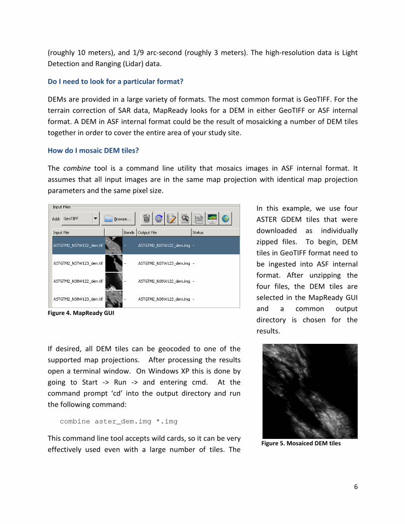
The combine tool is a command line utility that mosaics images in ASF internal format. It assumes that all input images are in the same map projection with identical map projection parameters and the same pixel size.
In this example, we use four ASTER GDEM tiles that were downloaded as individually zipped files. To begin, DEM tiles in GeoTIFF format need to be ingested into ASF internal format. After unzipping the four files, the DEM tiles are selected in the MapReady GUI and a common output directory is chosen for the results.
If desired, all DEM tiles can be geocoded to one of the supported map projections. After processing the results open a terminal window. On Windows XP this is done by going to Start -> Run -> and entering cmd. At the command prompt ‘cd’ into the output directory and run the following command:
combine aster_dem.img *.img
This command line tool accepts wild cards, so it can be very effectively used even with a large number of tiles. The
Figure 4. MapReady GUI
Figure 5. Mosaiced DEM tiles
7
resulting DEM can be used for the terrain correction within MapReady without any further processing.
What map projections can I use for my digital elevation model?
Most DEMs come in geographic coordinates because that makes the global distribution of the data in tiles more straight forward. MapReady supports DEM with geographic coordinates during the terrain correction, so there is no need to choose a particular map projection before the terrain correction. However, if your other data for the study area is in a particular map projection you could get the DEM into this map projection as well.
MapReady supports these five common map projections to choose from: • Universal Transverse Mercator (UTM)
• Albers Conical Equal Area
• Polar Stereographic
• Lambert Conformal Conic
• Lambert Azimuthal Equal Area
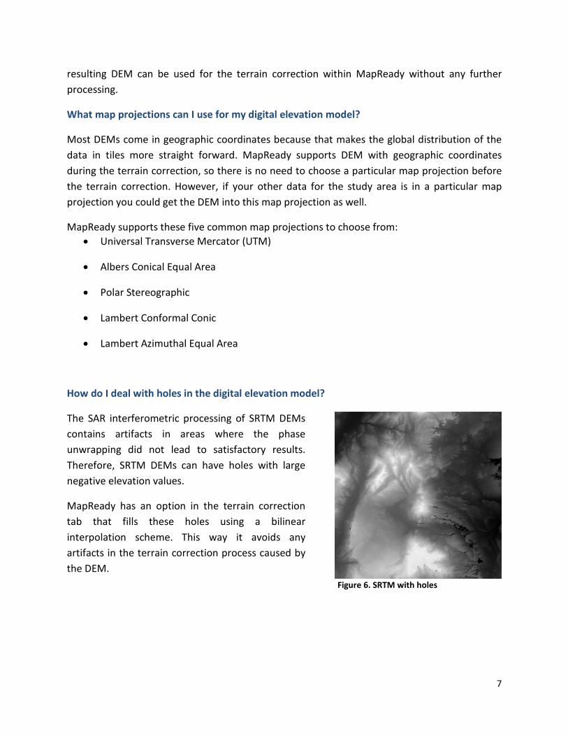
How do I deal with holes in the digital elevation model?
The SAR interferometric processing of SRTM DEMs contains artifacts in areas where the phase unwrapping did not lead to satisfactory results. Therefore, SRTM DEMs can have holes with large negative elevation values.
MapReady has an option in the terrain correction tab that fills these holes using a bilinear interpolation scheme. This way it avoids any artifacts in the terrain correction process caused by the DEM.
Figure 6. SRTM with holes

8
Generating a Mask for Terrain Correction
How do I define an area of interest?
In a first step, we need to determine our study area by defining the area of interest. This can be achieved in various ways.
If we have a well defined area of interest, e.g. a glacier, the boundary is known in its entirety with some detail. In this case, a shape file either already exists or can be generated by digitizing the boundary within ArcGIS.
In other cases, e.g. a land/water boundary defined by the coast line, needs to be treated differently. We typically use four corner coordinates for which we have geographic coordinates, i.e. latitude and longitude, to define our area of interest. More points can be used, if so desired, but this is generally not required. The corner coordinates are stored in a tab delimited file with three columns: point ID, latitude, longitude. Any text editor or an Excel spreadsheet can be used for this step.
This polygon file is then converted into a shape file using the convert2vector tool. The command line would look like this
convert2vector –i point –o shape cook_inlet.csv cook_inlet.shp
How do I generate a vector mask?
For our water body example we now need to clip the coast line to only cover our previously defined area of interest.
The clipping function is part of the 'Extract' functions of the analysis tool within the ArcToolbox. As shown in the example on the right, a coast line polygon (1:63,360 scale) is the input feature. The previously defined boundary file serves as a clip feature.
Figure 7. Clipping function in ArcGIS

9
Note that the resulting vector mask inherits the map projection information from the input feature. If you want to use a different projection during the terrain correction process, reproject the input feature into this projection before clipping the area of interest.
In case of a fully defined boundary, e.g. our glacier example, this step is not required.
Figure 8. Attribute table of the mask shape file
In the next step, add a new mask field to the attribute table (type: short integer) and set the mask attribute to 1. This is effectively done using 'Find and replace' in the options menu, once the table is in editing mode.
How do I generate a raster mask?
In order to use the vector mask in the terrain correction process, it needs to be converted to a raster format.
For that we convert the vector mask using the newly defined mask field into a raster format. In this step it is important to define the output cell size. The cell size should be same as the pixel size that we intend to use during the terrain correction. In the resulting raster mask image all pixels that are included in the area of interest are set to 1. All other pixels are set to 0.
Figure 9. Feature conversion tool in ArcGIS

10
By converting the raster mask image into the GeoTIFF format the mask can be used for the terrain correction of radar images within ASF’s MapReady software.
Note that this step preserves the map projection information introduced earlier.
Figure 10. Raster export interface in ArcGIS

11
UAVSAR
What is UAVSAR and what types of UAVSAR data are acquired?
UAVSAR, a reconfigurable, L-band synthetic aperture radar (SAR), is specifically designed to acquire airborne polarimetric and repeat track interferometric SAR data. All metadata for both data types is stored in an annotation file.
The polarimetric UAVSAR (PolSAR) data is acquired as quad-pol data. The single look complex slant range (SLC) data is not distributed by ASF. The multilook cross product slant range (MLC) images are more manageable in size and still in the original SAR geometry. The ground range projected and multi-looked (GRD) data are provided in geographic coordinates. The DEM height (HGT) data is projected in geographic coordinates as well. For backwards compatibility the polarimetric data is also stored as compressed Stokes matrix (DAT) of multi-looked data.
The repeat pass interferometry (RPI) data come in various products that are stored in different ways. Two amplitude images, from pass 1 (AMP1) and from pass 2 (AMP2), are processed from the two data sets that were used to generate all other interferometric products: the interferogram (INT), the unwrapped phase (UNW) and the correlation (COR) image. All these RPI products are available in slant range (all products described so far) and in projected ground range (AMP_GRD, INT_GRD, UNW_GRD, COR_GRD). The DEM height (HGT_GRD) is only available in projected ground range. The slant range complex (SLC) data are not distributed by ASF.
How is UAVSAR PolSAR data stored?
The UAVSAR PolSAR data is stored in two different ways. First, the data is provided by the elements of the covariance matrix C3. The main diagonal elements (HHHH, HVHV and VVVV) only contain real values, whereas the off-diagonal elements (HHHV, HHVV and HVVV) are complex and have, therefore, real and imaginary parts. Second, the data is provided as compressed Stokes matrix backwards compatible with AirSAR data.
How do I convert UAVSAR data in a GIS compatible format?
The UAVSAR GRD and HGT data are provided in geographic coordinates. Unless we want the data in another map projection we can skip the geocoding step. After ingesting the data, the UAVSAR data is internally stored as a regular covariance matrix C3. Then we export the files to GeoTIFF format to make the data GIS compatible. MapReady stores all C3 matrix elements in separate files. For complex matrix elements the real and imaginary part of saved separately.

12
Can I geocode UAVSAR data?
The UAVSAR GRD products are already geocoded. However, the UAVSAR PolSAR MLC products are still the SAR geometry they were acquired in.
Figure 11. UAVSAR MLC file selection
After loading the annotation file (.ann), the MLC products check box needs to be selected. For the geocoding you can select an of the predefined map projection. We use UTM for our example here.

13
Figure 12. Geocoded C11 MLC element
The individual C3 matrix elements have a very narrow value range and look, therefore, very dark.
Can I use UAVSAR data for polarimetric processing?
Yes, you can. Depending on what type of polarimetric processing you want to do, you have a few options. Some basic polarimetric processing, such as the generation of a Pauli decomposition, is implemented within MapReady. For any more complex polarimetric processing we would suggest PolSARPro (link to PolSARPro how to guide).
For this example, we will generate the Pauli decomposition with MapReady from the GRD files.

14
Figure 13. UAVSAR GRD file selection
In a first step, we select UAVSAR as our input format and browse for the annotation file (.ann). The annotation file is evaluated to see what files should be available and we can see from the available check boxes which UAVSAR products are actually on our disk.
Figure 14. MapReady Polarimetry tab
In the polarimetry tab, we have selected the Pauli decomposition. Even though the GRD products are already in geographic coordinates, we have chosen UTM coordinates for our result. In order to directly ingest the result into a GIS, we selected GeoTIFF as our output format.

15
Figure 15. Pauli decomposition derived from UAVSAR GRD data
16
PolSARPro and MapReady
What is PolSARPro?
The PolSARPro SAR Data Processing and Educational Tool was developed under contract to the European Space Agency (ESA) as a response to recommendations made at the PolInSAR workshop 2003 in Frascati, Italy (Pottier et al. 2009). It is the most comprehensive open source software for processing PolSAR and PolInSAR data. PolSARPro supports a large variety of space-borne and airborne data sources.
POTTIER, E., FERRO-FAMIL, L., ALLAIN, S., CLOUDE, S.R., HAJNSEK, I., PAPATHANASSIOU, K., MOREIRA, A., WILLIAMS, M., MINCHELLA, A., LAVALLE AND DESNOS, Y.L., 2009. Overview of the PolSARpro v4.0: The Open Source Toolbox for Polarimetric and Interferometric Polarimetric SAR Data Processing. Proceedings of IGARSS 2009, Cape Town, South Africa, 12-17 July 2009.
What polarimetric results does PolSARPro generate?
For the import into MapReady we distinguish between four different PolSARPro products.
The polarimetric segmentations represent the classification of polarimetric scattering mechanisms in different classes. The objective of polarimetric decompositions is to express the scattering matrix as a combination of distinct scattering responses. The polarimetric parameters such as entropy, anisotropy and alpha are based on the primary parameters of the eigen decomposition. The polarimetric matrices consist of all matrix elements, primarily the coherency matrix T3 or the covariance matrix C3.
Why do I need MapReady for PolSARPro products?
MapReady provides the functionality that PolSARPro is missing. It can geometrically and radiometrically terrain correct and geocode PolSARPro products. After exporting the data to a GeoTIFF format, the results can be used in a GIS environment.
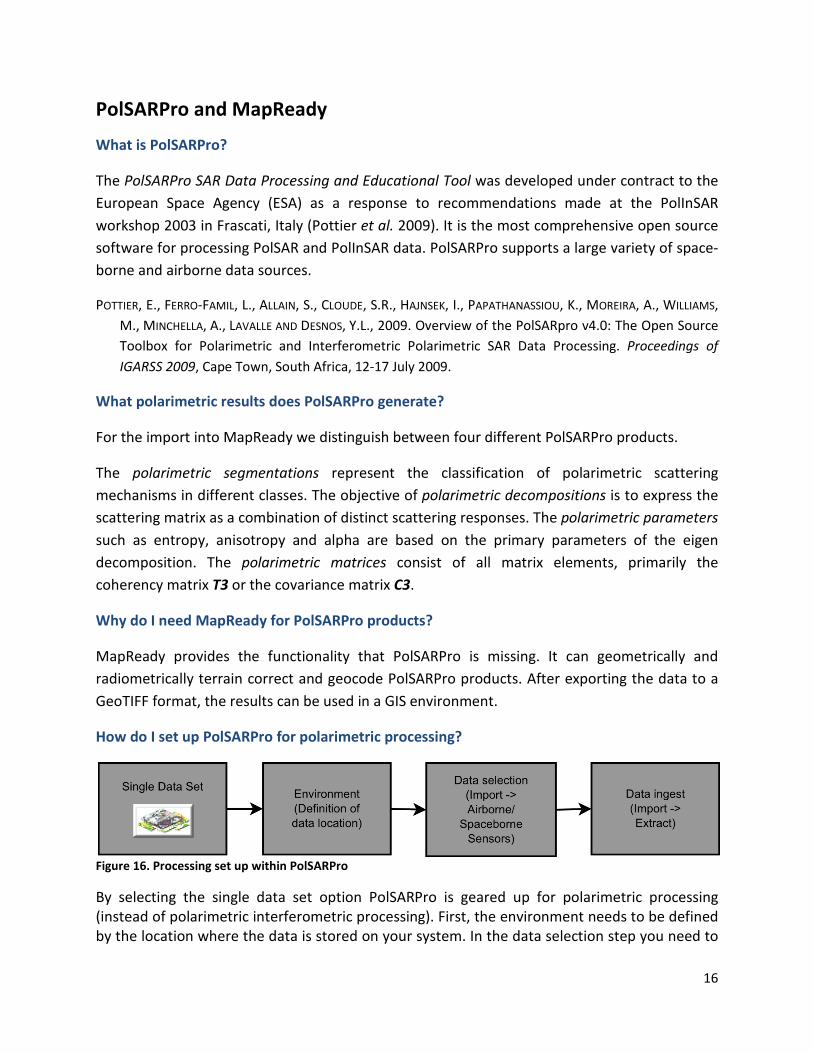
How do I set up PolSARPro for polarimetric processing?
Figure 16. Processing set up within PolSARPro
By selecting the single data set option PolSARPro is geared up for polarimetric processing (instead of polarimetric interferometric processing). First, the environment needs to be defined by the location where the data is stored on your system. In the data selection step you need to

17
assign a particular data set to the processing flow. The system needs to know from which airborne or spaceborne sensor your data is, what processing level it is at and what format it is provided in. After selecting the appropriate metadata file, PolASRPro will check the availability of all necessary files and read the header information. After that PolSARPro is ready to ingest the data. For fully polarimetric quad-pol data it then converts the scattering matrix S2 into a coherency matrix T3 or covariance matrix C3. For the processing itself the choice of matrix is not important. However, for any type of analysis the user should consider that the diagonal elements of the T3 matrix allow a physical interpretation. Should I multilook data in PolSARPro?
The polarimetric processing exploits the amplitude and phase information of a data sets. Therefore, the data used for this type of processing is provided as single look complex data. Depending of the data source that data should be multilooked when ingested into PolSARPro.
Table 1 gives some general guidelines about multilooking polarimetric data. Generally, ALOS Palsar data should be multilooked to create pixels which square pixel dimensions. Any other data can be imported in full resolution as they row/column ratio is close to 1. However, if the polarimetric results are later combined with other lower resolution data, it is actually advisable to use the multilook option with equal rows/cols settings to reduce the data volume. Especially the processing of airborne swath data such as UAVSAR can be very time consuming when done in its original pixel
size of about five meters. What UAVSAR data can be processed with PolSARPro?
PolSARPro supports UAVSAR data in three different format: SLC, MLC and GRD. The SLC data are not very practical for polarimetric processing due to its huge volume. The most useful formats are the multilooked data (MLC) and the terrain corrected ground range data (GRD). Both formats are provided in linear power scale in Gamma radiometry. For the ingest of GRD data into PolSARPro the height values, conveniently stored in the GRD files and the annotation file, are needed. For the majority of purposes the GRD files are the most viable data option.
Sensor Looks
Rows Cols
ALOS Palsar quad-pol
Mul
ti lo
ok 7 1
ALOS Palsar dual-pol 4 1
Radarsat-2 quad-pol
Full
reso
lutio
n 1 1
TerraSAR-X dual-pol 1 1
UAVSAR 1 1
Table 1. Multilook settings for polarimetric data

18
How do I geometrically terrain correct and geocode PolSARPro products?
We assume that you have done the polarimetric processing within PolSARPro, i.e. you imported the data into PolSARPro and generated the desired polarimetric result. In this example, we geometrically terrain correct and geocode an entropy image.
Figure 17. MapReady PolSARPro ingest interface
After selecting the entropy file out of the matrix directory, the interface evaluates whether the PolSARPro data is geocoded or not. In this case, the file is still in SAR geometry, so the original data file is required to retrieve the necessary metadata for terrain correction and geocoding. We want to visually analyze the entropy, so we select the appropriate colormap "polarimetry" before importing the file.
The MapReady processing is then carried out in the regular fashion. For the terrain correction a digital elevation model is required. In this case, the UTM predefined map projection is selected to geocode the entropy image. The final result is exported to GeoTIFF format to be GIS compatible for further analysis.

19
Figure 18. Geometrically terrain corrected and geocoded entropy image

20
Which PolSARPro products can be radiometrically terrain corrected?
The radiometric terrain correction of PolSARPro products is not supported in MapReady.
Is the difference between geometrically and radiometrically terrain corrected polarimetric results noticable?
Geometric terrain correction adjusts the individual pixels of an amplitude image to be in their proper location, while radiometric terrain correction adjusts the brightness of slopes directed towards the sensor. The example below shows the difference between a geometrically and a radiometrically terrain corrected Pauli decomposition. Within MapReady, terrain correction takes place on the amplitude image, the results of which are then used in polarimetric processing to generate a radiometrically terrain corrected Pauli decomposition.
Figure 19. Geometrically terrain corrected Pauli decomposition
Figure 20. Radiometrically terrain corrected Pauli decomposition

21
Creating KML overlays
How do I create KML overlays for a polarimetric parameter?
Command line: asf_kml_overlay -polsarpro parameter -colormap polarimetry entropy.bin entropy Date: 28-Nov-2010, 19:39:55 PID: 3676 Version: 9384 (part of MapReady 2.3.15-rc) A system independent zipping function is currently not available. For the moment the KML and PNG files need to be manually zipped together. Colormap (polarimetry) is applied to PolSARPro parameter ... ** Warning: ******** Upper left y corner error was too large! 2.740630 > 1.250000 ** End of warning ** ** Warning: ******** Lower right Y corner error was too large! 2.644046 > 1.250000 ** End of warning ** Generating entropy.kml ... Successful completion!
Figure 21. KML overlay of entropy

22
How do I create a KML overlay for a polarimetric segmentation?
Command line: asf_kml_overlay -polsarpro segmentation -colormap Wishart_H_Alpha_8 wishart_H_alpha_class_3.bin wishart_H_alpha_class Date: 28-Nov-2010, 20:29:07 PID: 284 Version: 9384 (part of MapReady 2.3.15-rc) A system independent zipping function is currently not available. For the moment the KML and PNG files need to be manually zipped together. Colormap (Wishart_H_Alpha_8) is applied to PolSARPro segmentation ... ** Warning: ******** Upper left y corner error was too large! 2.740630 > 1.250000 ** End of warning ** ** Warning: ******** Lower right Y corner error was too large! 2.644046 > 1.250000 ** End of warning ** Generating wishart_H_alpha_class.kml ... Successful completion!
Figure 22. KMLoverlay of a Wishart segmentation

23
How do I create a KML overlay for a polarimetric decomposition?
Command line: asf_kml_overlay -polsarpro decomposition -rgb Freeman_Dbl,Freeman_Vol,Freeman_Odd Freeman_Dbl.bin freeman Date: 02-Dec-2010, 23:02:59 PID: 4042 Version: 9384 (part of MapReady 2.3.15-rc) A system independent zipping function is currently not available. For the moment the KML and PNG files need to be manually zipped together. PolSARPro decomposition stored as RGB (Freeman_Dbl,Freeman_Vol,Freeman_Odd) ** Warning: ******** Upper left y corner error was too large! 2.740630 > 1.250000 ** End of warning ** ** Warning: ******** Lower right Y corner error was too large! 2.644046 > 1.250000 ** End of warning ** Generating freeman.kml ... Generating freeman.png ... Successful completion!
Figure 23. KML overlay of Freeman decomposition

24
How do I create a KML overlay for an interferogram?
Command line: asf_kml_overlay -band INTERFEROGRAM_PHASE -colormap interferogram insar_utm.img insar.kml Date: 08-Dec-2010, 15:17:03 PID: 14352 Version: 9389 (part of MapReady 2.3.15-rc) A system independent zipping function is currently not available. For the moment the KML and PNG files need to be manually zipped together. Generated insar.kml ... Generated insar_INTERFEROGRAM_RGB.png ... Successful completion!
Figure 24. KML overlay of an interferogram

25
How do I create a KML overlay for a coherence image?
Command line: asf_kml_overlay -band COHERENCE insar_utm.img insar.kml Date: 08-Dec-2010, 15:19:57 PID: 14358 Version: 9389 (part of MapReady 2.3.15-rc) A system independent zipping function is currently not available. For the moment the KML and PNG files need to be manually zipped together. Generated insar.kml ... Generated insar_COHERENCE.png ... Successful completion!
Figure 25. KML overlay of a coherence image

26
Creating plug-ins for the "External" tab
How to write a program that I can use as a plugin?
A plugin is a command line tool that takes an input file in ASF Internal Format and creates an output file in ASF Internal Format. Both filenames should be specified on the command line when running the program. A sample plugin program called “sample_plugin” has been provided in the MapReady source package that you can use to get started writing a plugin in C.
You do not need to write your plugins in C, however to take advantage of the ASF libraries (which contain code capable of ingesting the ASF Internal format, which you must use) to need to be able to call C code. Since the ASF Internal format contains metadata files that are plain text, and the data files are simple binary sequential raw data files, you do not need to use the ASF libraries to read ASF Internal files.
How do I add a plugin to MapReady?
The list of external tools in the drop-down list on the External Tab is read from the file “plugins.cfg” in the MapReady share directory (on Windows, this is the normal installation directory, by default C:\Program Files\ASF Tools\MapReady 2.2; on Unix systems, by default it is /usr/local/share/asf_tools/mapready). The file lists each plugin and how to run the command line tool. Here is an example of what you might add to the file for the sample_plugin program:
Name=Sample
Command=sample_plugin –log {Log} –offset $P1 {Input} {Output}
Comment=Adds the specified offset to all pixels in the image
P1=double,required,”%f”,”Offset”
When writing the plugin, you can add support for a –log option, as the sample_plugin does, and then the output of the program can be included in the MapReady log (available through “View Log”). This is optional, if your program doesn’t do logging you would leave out the “–log {Log}”.
Any additional information from the user needed by the program can be given using the parameter specifications (P1, P2, etc), one for each command-line option that can be given to the program with the added information.
“{Input}” and “{Output}” are required; they are placeholders where MapReady will put the filenames of the input and output files.

27
After these lines are added to plugins.cfg, the next time MapReady is run the external tools drop-down list should contain an additional entry “Sample”. In order for MapReady to be able to run the program, the compiled “sample_plugin” binary should be put somewhere in your PATH; for example, you could just put it into the MapReady binary directory.