asee 2005. kcide a knowledge capturing integrated design environment
TRANSCRIPT

ASEE 2005

ASEE 2005
KCIDEKCIDE
A Knowledge A Knowledge Capturing Capturing Integrated Integrated Design Design EnvironmentEnvironment

ASEE 2005

ASEE 2005
KCIDE for KCIDE for Electrical CircuitsElectrical Circuits
•A platform that runs on A platform that runs on top of Windowstop of Windows
•Integrates PSpice, Integrates PSpice, MATLAB, Excel, Word, MATLAB, Excel, Word, and PowerPointand PowerPoint
•Captures knowledgeCaptures knowledge

ASEE 2005
Based on the Systems Based on the Systems Approach to Problem Approach to Problem
SolvingSolving•The six step process as The six step process as presented in Alexander presented in Alexander and Sadikuand Sadiku

ASEE 2005
Six StepsSix Steps
•DefineDefine
•PresentPresent
•Alternate SolutionsAlternate Solutions

ASEE 2005
Six StepsSix Steps
•AttemptAttempt
•EvaluateEvaluate
•Rework/ExportRework/Export


9
10

11

12

13

14

15

16
17

18

19

20

21

22

23

24

25

26

27

28
29
30
31

Electric Circuits IDE
Problem Name: Example 03-02
Date: 6/9/2005

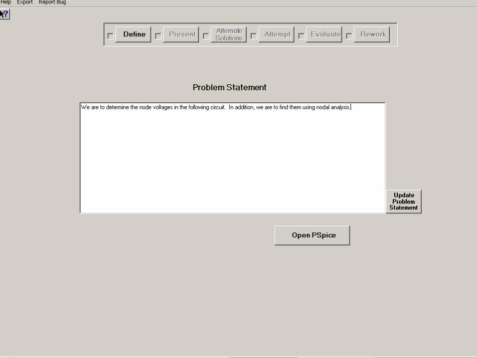
Problem Statement
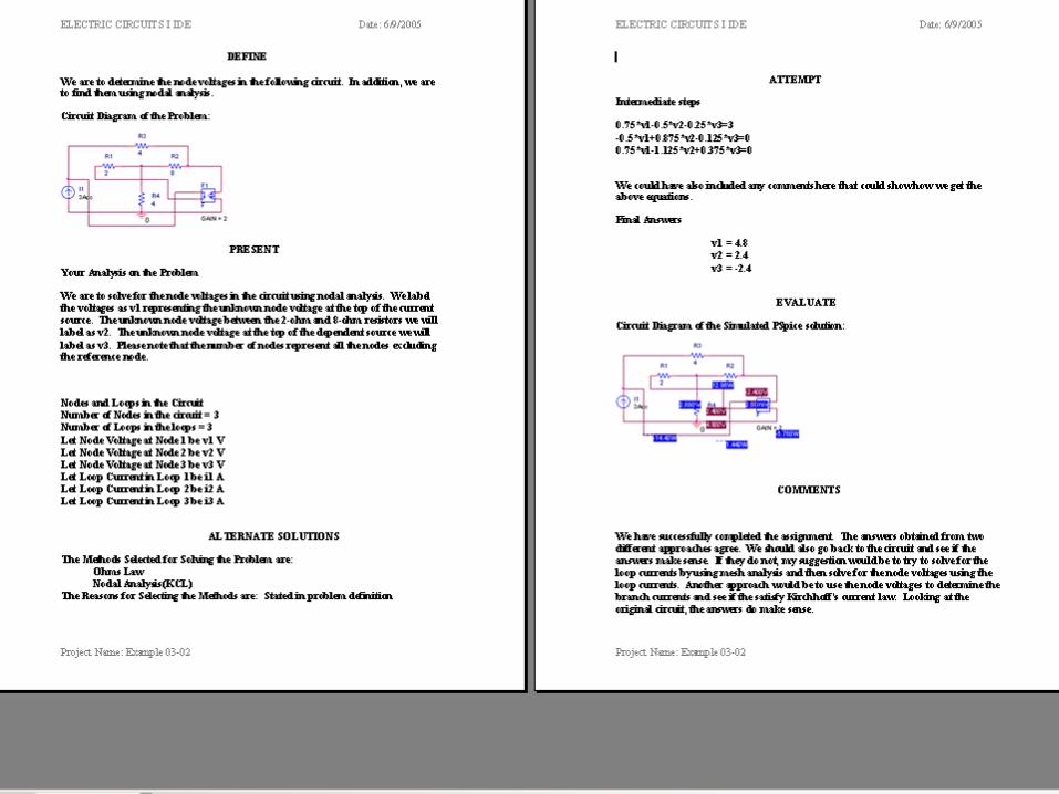
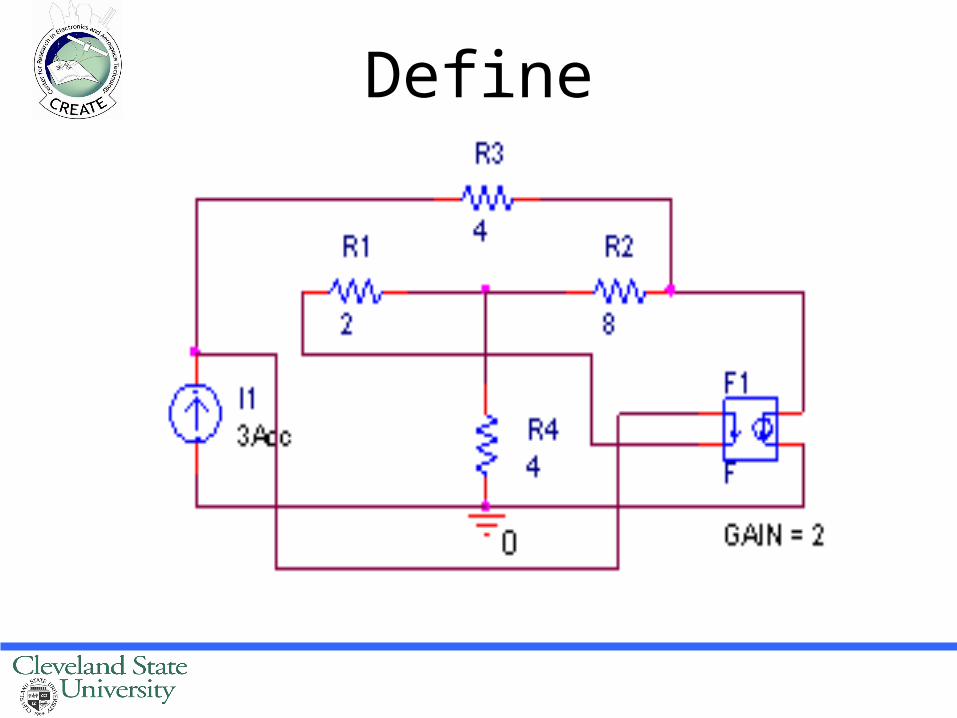
We are to determine the node voltages in the following circuit. In addition, we are to find them using nodal analysis.
Define

Your Analysis on the Problem
We are to solve for the node voltages in the circuit using nodal analysis. We label the voltages as v1 representing the unknown node voltage at the top of the current source. The unknown node voltage between the 2-ohm and 8-ohm resistors we will label as v2. The unknown node voltage at the top of the dependent source we will label as v3. Please note that the number of nodes represent all the nodes excluding the reference node.

Present
• Number of Nodes in the circuit are 3• Number of Loops in the loops are 3• Let Node Voltage at Node 1 be v1 V• Let Node Voltage at Node 2 be v2 V• Let Node Voltage at Node 3 be v3 V• Let Loop Current in Loop 1 be i1 A• Let Loop Current in Loop 2 be i2 A• Let Loop Current in Loop 3 be i3 A

ALTERNATE SOLUTIONS
The Methods Selected for Solving the Problem are:Ohms LawNodal Analysis(KCL)
The Reasons for Selecting the Methods are:Stated in problem definition
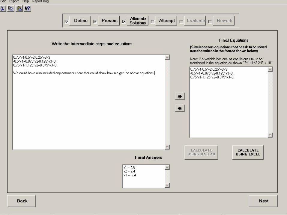
Attempt
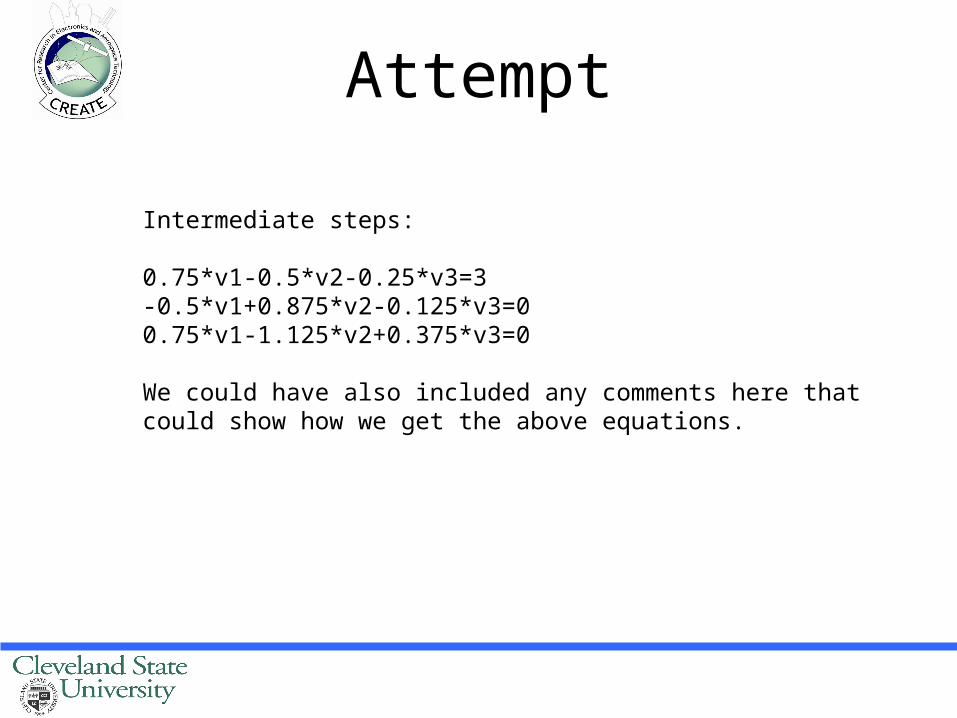
Intermediate steps:
0.75*v1-0.5*v2-0.25*v3=3-0.5*v1+0.875*v2-0.125*v3=00.75*v1-1.125*v2+0.375*v3=0
We could have also included any comments here that could show how we get the above equations.

ATTEMPT-II
Final Answers:
v1 = 4.8v2 = 2.4v3 = -2.4

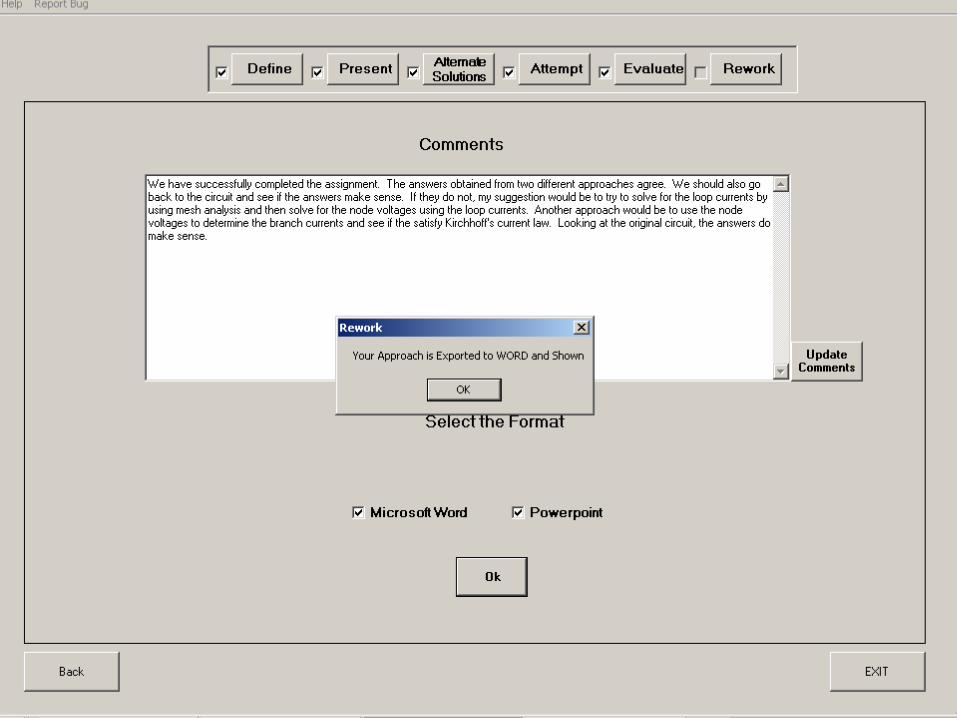
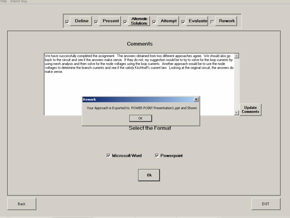
Evaluate

Comments
We have successfully completed the assignment. The answers obtained from two different approaches agree. We should also go back to the circuit and see if the answers make sense. If they do not, my suggestion would be to try to solve for the loop currents by using mesh analysis and then solve for the node voltages using the loop currents. Another approach would be to use the node voltages to determine the branch currents and see if the satisfy Kirchhoff's current law. Looking at the original circuit, the answers do make sense.

ASEE 2005
KCIDE for CircuitsKCIDE for Circuits
How to download the How to download the KCIDE for Circuits KCIDE for Circuits
software from the web software from the web site: site:
http://kcide.fennresearch.orghttp://kcide.fennresearch.org
IT IS FREE!!!!!!!IT IS FREE!!!!!!!

43
The Website: http://kcide.fennresearch.org

44
http://kcide.fennresearch.org/downloads.htm
Click Here

45Click Here

46
Fill out the form and click Submit

47
After a short while, you will receive an email with download
instructions.
Click on the link to complete the go to finish the downloads process.