artisan technology group is your source for quality ... · contents siemens ag dk-nr. 213741...
TRANSCRIPT

Artisan Technology Group is your source for quality new and certified-used/pre-owned equipment
• FAST SHIPPING AND DELIVERY
• TENS OF THOUSANDS OF IN-STOCK ITEMS
• EQUIPMENT DEMOS
• HUNDREDS OF MANUFACTURERS SUPPORTED
• LEASING/MONTHLY RENTALS
• ITAR CERTIFIED SECURE ASSET SOLUTIONS
SERVICE CENTER REPAIRSExperienced engineers and technicians on staff at our full-service, in-house repair center
WE BUY USED EQUIPMENTSell your excess, underutilized, and idle used equipment We also offer credit for buy-backs and trade-inswww.artisantg.com/WeBuyEquipment
REMOTE INSPECTIONRemotely inspect equipment before purchasing with our interactive website at www.instraview.com
LOOKING FOR MORE INFORMATION? Visit us on the web at www.artisantg.com for more information on price quotations, drivers, technical specifications, manuals, and documentation
Contact us: (888) 88-SOURCE | [email protected] | www.artisantg.com
SMViewInstra
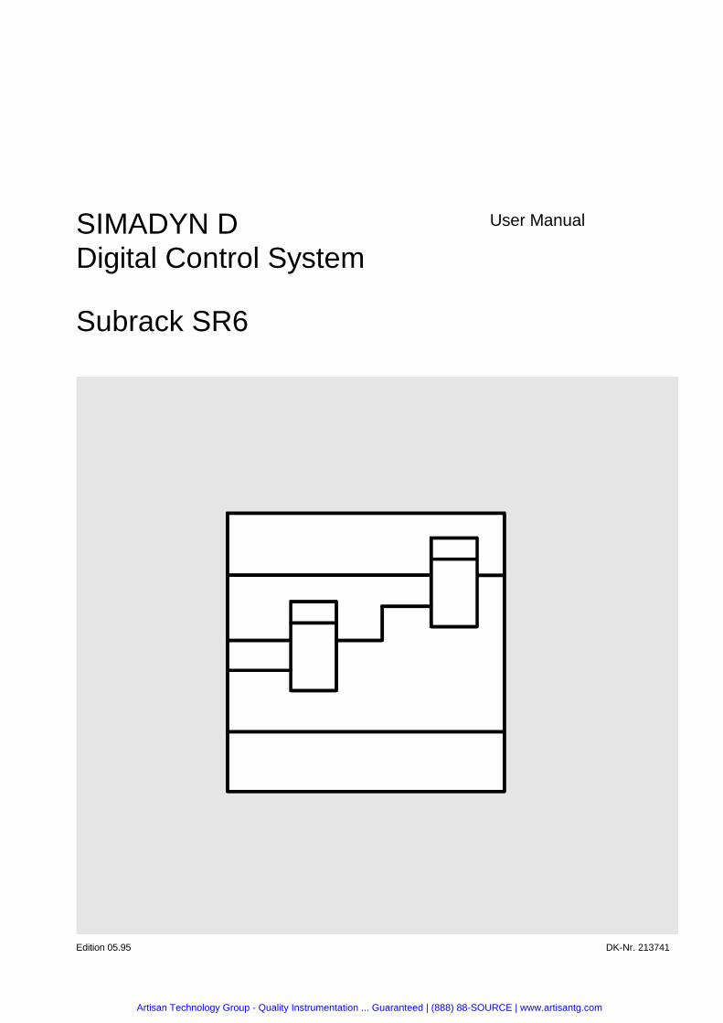
SIMADYN DDigital Control System
Subrack SR6
User Manual
Edition 05.95 DK-Nr. 213741
Artisan Technology Group - Quality Instrumentation ... Guaranteed | (888) 88-SOURCE | www.artisantg.com
User Manual, Subrack SR6
Edition Edition status
1 Subrack SR6 05.95
Copying of this document and giving it to others and the use orcommunication of the contents thereof is forbidden without expressauthority. Offenders are liable to the payment of damages. All rightsare reserved in the event of the grant of a patent or the registration ofa utility model or design.
We have checked the contents of this Manual to ensure that theycoincide with the described hardware and software. However,deviations cannot be completely ruled-out, so we cannot guaranteecomplete conformance. However, the information in this document isregularly checked and the necessary corrections included insubsequent editions. We are thankful for any recommendations orsuggestions.
Artisan Technology Group - Quality Instrumentation ... Guaranteed | (888) 88-SOURCE | www.artisantg.com
Contents
Siemens AG Dk-Nr. 213741 Edition 05.95SIMADYN D Hardware User Manual
Contents
Warning information................................ ................................ ................................ ....................11. Ordering Information ................................ ................................ ................................ ...............32. Function Description ................................ ................................ ................................ ...............33. Bus System................................ ................................ ................................ ............................. 3
3.1. Bus Board................................ ................................ ................................ ................33.2. Bus Arbitration ................................ ................................ ................................ .........33.3. Bus Termination................................ ................................ ................................ .......6
4. Power Supply................................ ................................ ................................ .......................... 64.1. Layout................................ ................................ ................................ ......................64.2. Design ................................ ................................ ................................ .....................6
4.2.1. Front Panel Elements and Funktions................................ .........................64.2.2. Monitoring Functions ................................ ................................ .................7
4.3. Technical Data................................ ................................ ................................ .........74.4. Battery Buffering of the RAM Memory................................ ................................ ......10
5. Installation Regulations................................ ................................ ................................ ...........115.1. Interference Protection................................ ................................ ............................. 115.2. Non- Ventilated Cooling................................ ................................ ........................... 11
6. Connector Assignments ................................ ................................ ................................ ..........126.1. Connector Assignments of the Power Supply................................ ........................... 12
6.1.1. Line Supply 230 V AC................................ ................................ ................126.1.2. Battery Connection................................ ................................ ....................126.1.3. Base Connector Supply................................ ................................ .............13
6.2. Signal Assigments on the Back Plane Bus................................ ............................... 147. STRUC L-Screen in the Master Program................................ ................................ .................158. Appendices................................ ................................ ................................ ............................. 15
8.1. Bus Board................................ ................................ ................................ ................158.2. Scale Drawing................................ ................................ ................................ ..........15
9. ECB instructions................................ ................................ ................................ ......................16
Artisan Technology Group - Quality Instrumentation ... Guaranteed | (888) 88-SOURCE | www.artisantg.com
Warning information
Edition 05.95 Siemens AG Dk-Nr. 213741SIMADYN D Hardware User Manual
Artisan Technology Group - Quality Instrumentation ... Guaranteed | (888) 88-SOURCE | www.artisantg.com
Warning information
Siemens AG Dk-Nr. 213741 Edition 05.95 1SIMADYN D Hardware User Manual
N O T E !
The information in this Manual does not purport to cover all details or variations in equipment, nor to providefor every possible contingency to be met in connection with installation, operation or maintenance.
Should further information be desired or should particular problems arise which are not covered sufficiently forthe purchaser’s purposes, please contact your local Siemens office.
Further, the contents of this Manual shall not become a part of or modify any prior or existing agreement,committment or relationship. The sales contract contains the entire obligation of Siemens. The warrantycontained in the contract between the parties is the sole warranty of Siemens. Any statements containedherein do not create new warranties nor modify the existing warranty.
Warning information
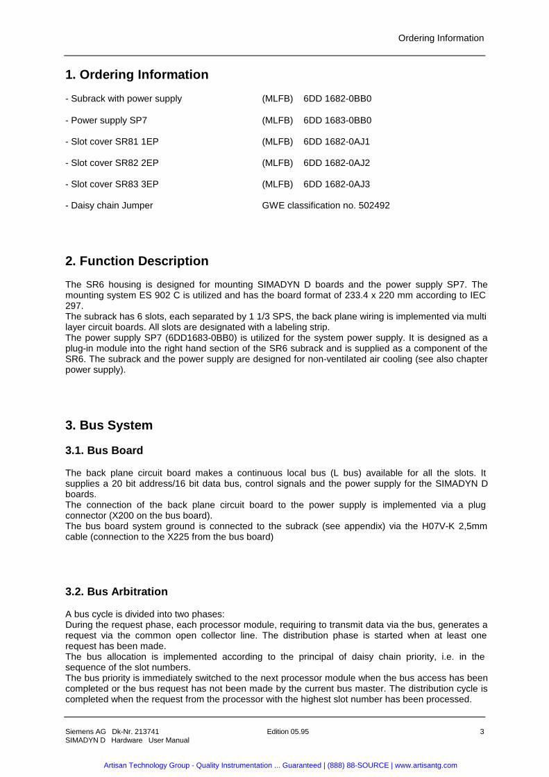
W A R N I N G !
Electrical equipment has components which are at dangerous voltage levels.
If these instructions are not strictly adhered to, severe bodily injury and materialdamage can result.
Only appropriately qualified personnel may work on this equipment or in itsvicinity.
This personnel must be completely knowledgeable about all the warnings andservice measures according to this User Manual.
The successful and safe operation of this equipment is dependent on properhandling, installation, operation and maintenance.
Artisan Technology Group - Quality Instrumentation ... Guaranteed | (888) 88-SOURCE | www.artisantg.com

Warning information
2 Edition 05.95 Siemens AG Dk-Nr. 213741SIMADYN D Hardware User Manual
Definitions
* QUALIFIED PERSONNELFor the purpose of this User Manual and product labels, a „Qualified person“ is someone who is familiar with theinstallation, mounting, start-up and operation of the equipment and the hazards involved. He or she must havethe following qualifications:1. Trained and authorized to energize, de-energize, clear, ground and tag circuits and equipment in accordancewith established safety procedures.2. Trained in the proper care and use of protective equipment in accordance with established safetyprocedures.3. Trained in rendering first aid.
* DANGERFor the purpose of this User Manual and product labels, „Danger“ indicates death, severe personal injury and/orsubstantial property damage will result if proper precautions are not taken.
* WARNINGFor the purpose of this User Manual and product labels, „Warning“ indicates death, severe personal injury orproperty damage can result if proper precautions are not taken.
* CAUTIONFor the purpose of this User Manual and product labels, „Caution“ indicates that minor personal injury ormaterial damage can result if proper precautions are not taken.
* NOTEFor the purpose of this User Manual, „Note“ indicates information about the product or the respective part of theUser Manual which is essential to highlight.
C A U T I O N !
This board contains components which can be destroyed by electrostaticdischarge. Prior to touching any electronics board, your body must be electricallydischarged. This can be simply done by touching a conductive, grounded objectimmediately beforehand (e.g. bare metal cabinet components, socket protectiveconductor contact).
W A R N I N G !
Hazardous voltages are present in this electrical equipment during operation.
Non-observance of the safety instructions can result in severe personal injury orproperty damage.
It is especially important that the warning information in all of the relevantOperating Instructions are strictly observed.
Artisan Technology Group - Quality Instrumentation ... Guaranteed | (888) 88-SOURCE | www.artisantg.com
Ordering Information
Siemens AG Dk-Nr. 213741 Edition 05.95 3SIMADYN D Hardware User Manual
1. Ordering Information
- Subrack with power supply (MLFB) 6DD 1682-0BB0
- Power supply SP7 (MLFB) 6DD 1683-0BB0
- Slot cover SR81 1EP (MLFB) 6DD 1682-0AJ1
- Slot cover SR82 2EP (MLFB) 6DD 1682-0AJ2
- Slot cover SR83 3EP (MLFB) 6DD 1682-0AJ3
- Daisy chain Jumper GWE classification no. 502492
2. Function Description
The SR6 housing is designed for mounting SIMADYN D boards and the power supply SP7. Themounting system ES 902 C is utilized and has the board format of 233.4 x 220 mm according to IEC297.The subrack has 6 slots, each separated by 1 1/3 SPS, the back plane wiring is implemented via multilayer circuit boards. All slots are designated with a labeling strip.The power supply SP7 (6DD1683-0BB0) is utilized for the system power supply. It is designed as aplug-in module into the right hand section of the SR6 subrack and is supplied as a component of theSR6. The subrack and the power supply are designed for non-ventilated air cooling (see also chapterpower supply).
3. Bus System
3.1. Bus Board
The back plane circuit board makes a continuous local bus (L bus) available for all the slots. Itsupplies a 20 bit address/16 bit data bus, control signals and the power supply for the SIMADYN Dboards.The connection of the back plane circuit board to the power supply is implemented via a plugconnector (X200 on the bus board).The bus board system ground is connected to the subrack (see appendix) via the H07V-K 2,5mmcable (connection to the X225 from the bus board)
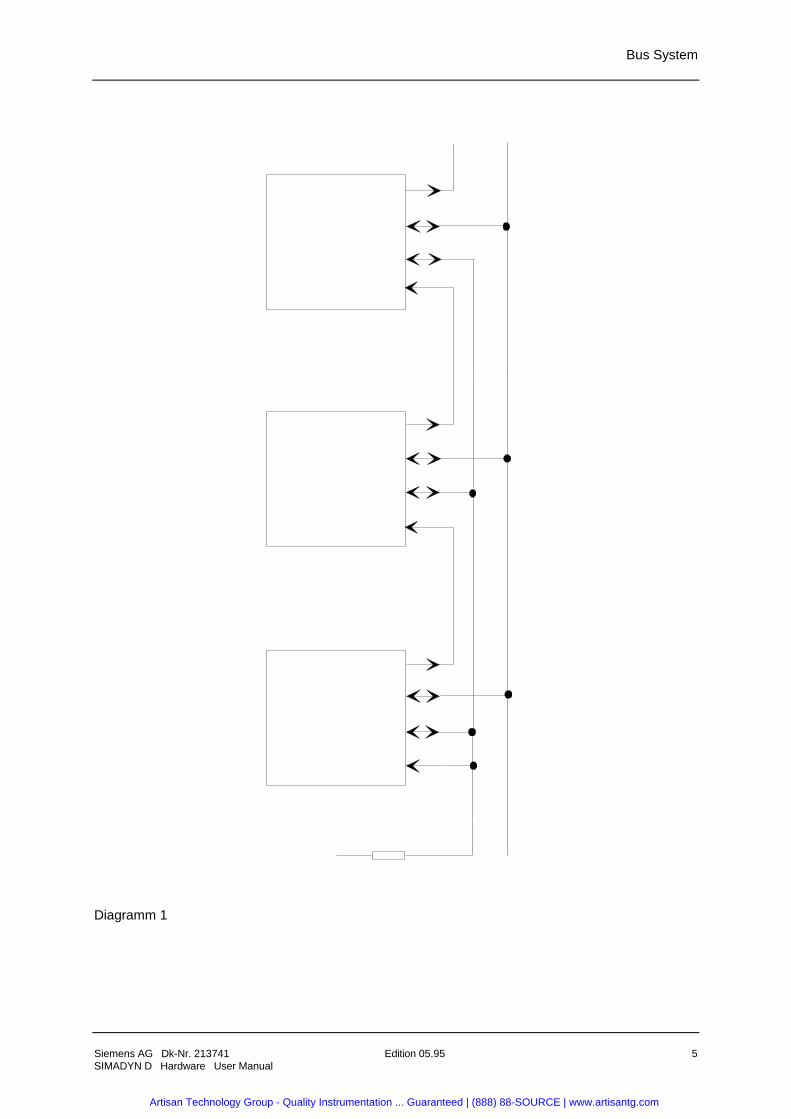
3.2. Bus Arbitration
A bus cycle is divided into two phases:During the request phase, each processor module, requiring to transmit data via the bus, generates arequest via the common open collector line. The distribution phase is started when at least onerequest has been made.The bus allocation is implemented according to the principal of daisy chain priority, i.e. in thesequence of the slot numbers.The bus priority is immediately switched to the next processor module when the bus access has beencompleted or the bus request has not been made by the current bus master. The distribution cycle iscompleted when the request from the processor with the highest slot number has been processed.
Artisan Technology Group - Quality Instrumentation ... Guaranteed | (888) 88-SOURCE | www.artisantg.com
Bus System
4 Edition 05.95 Siemens AG Dk-Nr. 213741SIMADYN D Hardware User Manual
New requests can only be made when the common open collector line has become inactive.This arbitration process then insures that each processor module is processed once within adistribution cycle. The maximum wait time for a processor with the highest slot number can total up tothree bus accesses (P3 missed the request phase, P1-2 become active and immediately request thenext cycle). A bus access is normally approximately 1 ms long (without continuous request or LOCK).
The complete arbitration will only function when the daisy chain line is correctly looped from the firstto the last processor of a bus section. Two connector pins (X1...X5, the slot 6 contains no connector(X201...X206).They must always be jumpered when no SIMADYN D board is mounted on the corresponding socketconnector.The jumper plugs must be removed when a SIMADYN D processor board is mounted on thecorresponding socket connector.The subrack is supplied with a complete set of connector pins.
Artisan Technology Group - Quality Instrumentation ... Guaranteed | (888) 88-SOURCE | www.artisantg.com
Bus System
Siemens AG Dk-Nr. 213741 Edition 05.95 5SIMADYN D Hardware User Manual
Diagramm 1
Artisan Technology Group - Quality Instrumentation ... Guaranteed | (888) 88-SOURCE | www.artisantg.com
Power Supply
6 Edition 05.95 Siemens AG Dk-Nr. 213741SIMADYN D Hardware User Manual
3.3. Bus Termination
The bus lines must be correctly terminated in order to achieve defined voltage levels on the bus lines.The bus termination resistances required for this are available on the system boards MM11, MM21und SR17. They become active when the memory link is installed.
The boards
PT20 6DD1606-1AC0PT20G 6DD1606-2AC0
can be operated without bus termination. They can however not access peripheral boards without bustermination.
4. Power Supply
4.1. Layout
The power supply is designed as a slot module for the SIMADYN D subrack system ES 902 C. Thedimensions L x W x D are 220 x 233.4 x 45.72mm. The subrack is designed for non-ventilated aircooling. The slot module is fixed by screw mounting. The power line connections, LED’s test jacksand the battery connection can be accessed on the front panel.
The power supply is located at the right hand slot of the SR6 subrack. The aluminum side walltowards the boards is a screen for insulation and radio noise emissions. The heat losses are thereforeextracted from the side away from the boards.
The front panel corresponds to the usual SIMADYN D design. The front panel also contains a powerline cable grip (see also MB).
4.2. Design
4.2.1. Front Panel Elements and Funktions
Front view of the SP7 (see also MB).
- Indicate the fault free operational readiness via an LED (green) on the front panel.
- Indicate an internal fault of the power supply by means of an LED (red) on the fronz panel (internal power supply fault when an under voltage monitor of the output voltages Ua1, Ua2, Ua3 or the inputvoltage Ue is activated).
- Reset push button on the front panel of the power supply; activates a power supply switch off/switch on routine.
Press --> Activate switch off routineRelease --> Automatic restart
The reset push button is safeguarded against unintentional activation (reset mounted, simple activation (i.e. by means of a ball point pen)).
Artisan Technology Group - Quality Instrumentation ... Guaranteed | (888) 88-SOURCE | www.artisantg.com
Power Supply
Siemens AG Dk-Nr. 213741 Edition 05.95 7SIMADYN D Hardware User Manual
- Test jacks on the front panel for checking the output voltages Ua1, Ua2, Ua3, (via protection impedances as short circuit protection).
- The battery connection is implemented via the front panel: Phoenix terminal MSTB 2.5/3-ST.
- The power line connection is carried out via a 4 pin Phoenix terminal MSTB 2.5/4-T. The line fuse is 2 pin and internally mounted on the printed circuit board ( and an additional fuse SI 3).
Type and Designation: T800mA : SI 1, T800mA : SI2 und T50mA : SI 3.
Values: Input current (for Ue =230V ) : IN = 600mA
Melting integral : I2*t = 0,5A2*s
Inrush peak current : Is = 25A
4.2.2. Monitoring Functions
The input voltage and all output voltages are monitored for under voltage.
- Start of the switch off sequence:
Below range of Ue (230VAC) < 170 ...175VUa1 (5V) < 4,7 ... 4,85V (t>100-200 us)
Subsequent to the power supply being switched off by the input voltage monitoring equipment, forfalling below range, an automatic restart is implemented after resolving the cause of the fault (inputvoltage rises up to 190V). The down time period is undefined!No automatic restart occurs after the power supply is switched off by the monitoring equipment of theoutput voltage 5V. The power up occurs, after resolution of the cause of the fault, by switching thesupply voltage off and on.The switch off sequence can no longer be implemented when a short circuit occurs at the output!
- Indicate power supply faulty with control signal *RDYIN = LOW ,
when Ua2 (+15V) < 13,0 ... 14,0V andUa3 (-15V) > -14,0 ...-13,0V falls below range.
4.3. Technical Data
1. Input voltages:
AC supply according to SN 2655 Section 8, DIN IEC 38 specificationsUe: 230V
Static upper limit: Ue * 1,1 (=253V)Static lower limit: Ue * 0,85 (=195,5V)Frequency: 50/60 Hz ± 2,5Hz
Non periodical over voltages according to DIN VDE160, A5.3.1.1.2
U based on peak value : Ue * 1,3 (460V)Period : 1,3 msRecovery time at least: 0,1 s
Artisan Technology Group - Quality Instrumentation ... Guaranteed | (888) 88-SOURCE | www.artisantg.com
Power Supply
8 Edition 05.95 Siemens AG Dk-Nr. 213741SIMADYN D Hardware User Manual
Events per hour: 10 maximum
Artisan Technology Group - Quality Instrumentation ... Guaranteed | (888) 88-SOURCE | www.artisantg.com
Power Supply
Siemens AG Dk-Nr. 213741 Edition 05.95 9SIMADYN D Hardware User Manual
Transient voltage dips according to DIN VDE 0160, A5.3.1.1.3
U based on effective value: Ue * 1 (230V)Period : 5 msRecovery time at least: 0,1 sEvents per hour: 10 maximum
Vcc : +5V
2. Output Voltages/Current : Ua1: +5,1V ± 0,1V
Ripple : 50mVssIa1 : 1,5 bis 7 ABase load : 1,5A, the defined values are valid above the base load.
Ua2: +15V ± 0,300V
Ripple : 150mVssIa2 : 0 bis 0,7 ABase load : 0,05*Ia2 rated
Ua3: -15V ± 0,300VRipple : 150mVssIa3 : 0 bis 0,6 ABase load : 0,05*Ia3 rated
3. Over Voltage Protection : for Ua1 (Surpressor Diode)
4. Current Limiting : Ia1max = approx. 1,2*Ia1 ratedIa2max = approx . 1,2*Ia2 ratedIa3max = approx . 1,2*Ia3 rated
5. Control Accuracy : Conform with the values in section 1,2
6. Transient Recovery Time for Ua1: < 80ms after Ue=Ue rated<1ms after load step (0,5 -->1)*Ia1 rated
7. Residual Ripple: < 50 mVss for Ua1< 150 mVss for Ua2,Ua3
Measurement Conditions: Probe 1:1, 10% base load, measurement band width 30 MHz
8. Commutation Peaks : < 5% of Ua rated
9. External Switch -On/Off : Via line switch
10. Input Protection : Fuse
11. Safety Regulations: Safe isolation according to VDE 0160
12. Insulation Voltage : 3750 V AC
Artisan Technology Group - Quality Instrumentation ... Guaranteed | (888) 88-SOURCE | www.artisantg.com
Power Supply
10 Edition 05.95 Siemens AG Dk-Nr. 213741SIMADYN D Hardware User Manual
Test Voltage : 3750 V AC13. Radio Interference Suppression Level : Limit value class B according to VDE 0871
14. Temperature Coefficient : Comply with values in Section 1.2 within Section 15
15. Working Temperature Range : 0 deg. C ± 55 deg. C , non-ventilated air cooling
16. Storage Temperature Range : -25 deg.C - + 85 deg.C
17. Ventilation : Internal, non-ventilated
18. Humidity Class : F according to DIN 40040
19. Protection Class : According to VDE 0106 / IEC536
20. Contamination Grade : 2 according to VDE 0110
21. Air and Leakage Path : According to VDE 0110
22. Connection Technology : See chapter 6 of this specification
23. Shock/Vibration Loading : Stationary installation: severity 12 according to SN29010Transport: severity 22 according to SN29010
24. Protection Class : IP00
25. Elevation Class : S according to DIN 40050
26. Discharge Current : 1mA according to VDE 0160
4.4. Battery Buffering of the RAM Memory
The SR6 subrack does not contain its own battery for retaining the RAM memory data when thepower supply fails. A battery can be connected via the plug connector X2. The voltage fed into X2/pin1 must lie between 3.0 V and 4.5 V. When lithium batteries are utilized, a protection component mustbe connected into the current path in order to prevent an impermissibly high charging current whenfaults occur (danger of explosion). A resistor in series of 39 Ohm is recommended. The battery isloaded with a maximum of 100 mA.
Possibly available monitoring of the battery voltage (U< 3.0 V) can be reported to the system viaX2/pin 2. Connect the 5V level at X2/pin 2 (*BATAL) to X2/pin 1 (M) with a low resistance. The currentoccurring at the jumpered connections X2/pin 2 and X2/pin 1 is a maximum of 0.5 mA( Ri = 10 KOhm ).
Lithium- Battery 3,6V 5,0Ah GWE-Classification No.: 247 239
Artisan Technology Group - Quality Instrumentation ... Guaranteed | (888) 88-SOURCE | www.artisantg.com
Installation Regulations
Siemens AG Dk-Nr. 213741 Edition 05.95 11SIMADYN D Hardware User Manual
5. Installation Regulations
5.1. Interference Protection
The SIMADYN D ground is fixed to the housing and therefore lies at ground line potential.
- All SIMADYN D housings must be connected to the cubicle ground with the shortest possible 6 mm2
cable. Voltage equalization via the “PE“ connection of the power supply is not sufficient.
- Screened cables must have their screen directly connected to the ground or a screen rail. The screen must run up to the terminal module or board.
- All switch gear cubicles actively participating on meshed SIMADYN D drives must be connected together with a single potential equalizing cable with a cross section of at least 16 mm2.
- Empty slots must be covered with SIMADYN D slot cover panels (SR81,SR82,SR83).
- All boards must be fixed with screws.
- No unsuppressed circuit breakers may be used in a switch gear cubicle with SIMADYN D.
- If unsuppressed circuit breakers are utilized in a cubicle next to the SIMADYN D cubicle, then the cubicles must be separated by side wall panels.
- The protective cable connection is implemented on the rack and the power supply. Both components (rack and power supply) must be connected to ground cable potential. This can be implemented for the rack by fixing with serrated edge washers. Disconnect the connection cables ofthe power supply before removing the power supply.
5.2. Non- Ventilated Cooling
The SIMADYN D rack SR6 is designed for non-ventilated cooling. In order to ensure the effectivnessof the internal fan cooling, sufficient exhaust possibilities must be exist at the rack and in the cubiclefor the rack exhaust air.
That signifies that the rack cannot be operated in an enclosed cubicle and that racks exhaust air is notconstricted by other units or components. The same applies for the racks intake air. The ventilationslits in the cubicle must not be covered with a filter.
If the rack is operated in an enclosed cubicle, then it must be forced air ventilated.
A minimum distance above or below the rack of 60 mm must be adhered to when mounting units orother components. Therefore two racks mounted above one another require a distance between bothracks of 120 mm, whereby the upper rack must be protected from the exhaust air of the lower rack bya deflection plate.
The rack may only be operated with processor boards from supply dates after 03.89 (lower powerlosses from the C-MOS components).
Artisan Technology Group - Quality Instrumentation ... Guaranteed | (888) 88-SOURCE | www.artisantg.com
Connector Assignments
12 Edition 05.95 Siemens AG Dk-Nr. 213741SIMADYN D Hardware User Manual
6. Connector Assignments
6.1. Connector Assignments of the Power Supply
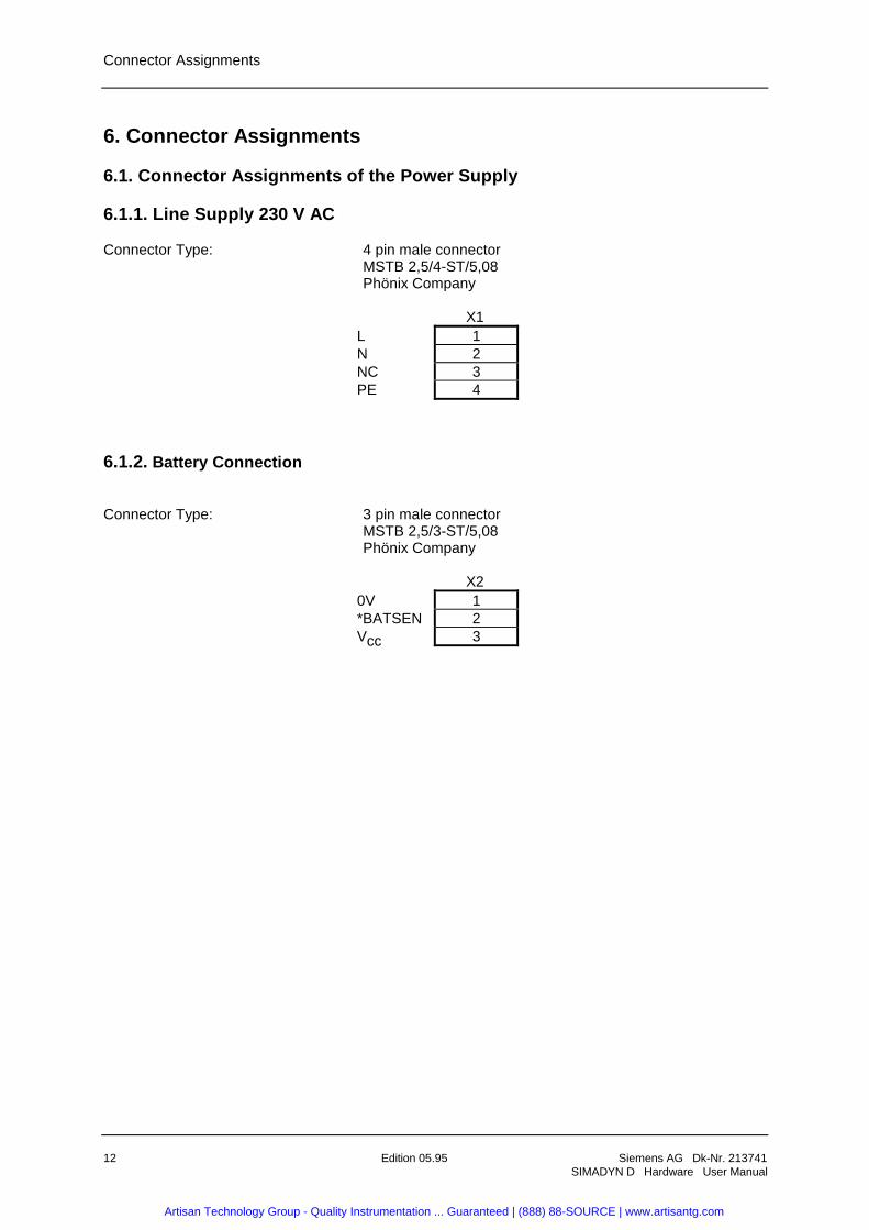
6.1.1. Line Supply 230 V AC
Connector Type: 4 pin male connectorMSTB 2,5/4-ST/5,08Phönix Company
X1L 1N 2NC 3PE 4
6.1.2. Battery Connection
Connector Type: 3 pin male connectorMSTB 2,5/3-ST/5,08Phönix Company
X20V 1*BATSEN 2Vcc 3
Artisan Technology Group - Quality Instrumentation ... Guaranteed | (888) 88-SOURCE | www.artisantg.com
Connector Assignments
Siemens AG Dk-Nr. 213741 Edition 05.95 13SIMADYN D Hardware User Manual
6.1.3. Base Connector Supply
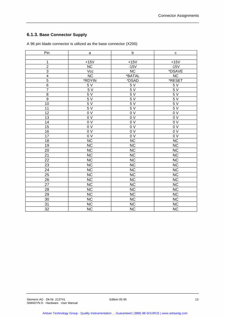
A 96 pin blade connector is utilized as the base connector (X200)
Pin a b c
1 +15V +15V +15V 2 NC -15V -15V 3 Vcc NC *DSAVE 4 NC *BATAL NC 5 *RDYIN *DSAD *RESET 6 5 V 5 V 5 V 7 5 V 5 V 5 V 8 5 V 5 V 5 V 9 5 V 5 V 5 V10 5 V 5 V 5 V11 5 V 5 V 5 V12 0 V 0 V 0 V13 0 V 0 V 0 V14 0 V 0 V 0 V15 0 V 0 V 0 V16 0 V 0 V 0 V17 0 V 0 V 0 V18 NC NC NC19 NC NC NC20 NC NC NC21 NC NC NC22 NC NC NC23 NC NC NC24 NC NC NC25 NC NC NC26 NC NC NC27 NC NC NC28 NC NC NC29 NC NC NC30 NC NC NC31 NC NC NC32 NC NC NC
Artisan Technology Group - Quality Instrumentation ... Guaranteed | (888) 88-SOURCE | www.artisantg.com
Connector Assignments
14 Edition 05.95 Siemens AG Dk-Nr. 213741SIMADYN D Hardware User Manual
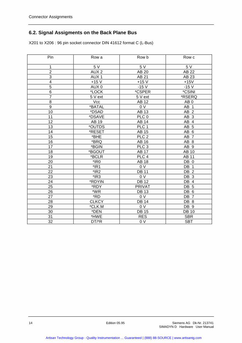
6.2. Signal Assigments on the Back Plane Bus
X201 to X206 : 96 pin socket connector DIN 41612 format C (L-Bus)
Pin Row a Row b Row c
1 5 V 5 V 5 V2 AUX 2 AB 20 AB 223 AUX 1 AB 21 AB 234 +15 V +15 V +15V5 AUX 0 -15 V -15 V6 *LOCK *CSPER *CSINI7 5 V ext 5 V ext *RSERQ8 Vcc AB 12 AB 09 *BATAL 0 V AB 1
10 *DSAD AB 13 AB 211 *DSAVE PLC 0 AB 312 AB 19 AB 14 AB 413 *OUTDS PLC 1 AB 514 *RESET AB 15 AB 615 *BHE PLC 2 AB 716 *BRQ AB 16 AB 817 *BGIN PLC 3 AB 918 *BGOUT AB 17 AB 1019 *BCLR PLC 4 AB 1120 *IR0 AB 18 DB 021 *IR1 0 V DB 122 *IR2 DB 11 DB 223 *IR3 0 V DB 324 *RDYIN DB 12 DB 425 *RDY PRIVAT DB 526 *WR DB 13 DB 627 *RD 0 V DB 728 CLKCY DB 14 DB 829 *CLK.M 0 V DB 930 *DEN DB 15 DB 1031 *HWE RES SBR32 DT/*R 0 V SBT
Artisan Technology Group - Quality Instrumentation ... Guaranteed | (888) 88-SOURCE | www.artisantg.com
STRUC L-Screen in the Master Program
Siemens AG Dk-Nr. 213741 Edition 05.95 15SIMADYN D Hardware User Manual
7. STRUC L-Screen in the Master Program
: SR6 "Rack 6 slots, L-Bus"L01 4S = '. . . . ´"Label"L05 4S = '. . .- - - - - - SP - - - - ´"Strips"S01 8N = ? "Slot 1: board (,sub-module)"S02 8N = 0S03 8N = 0S04 8N = 0S05 8N = 0S06 8N = 0++++++++++++++++++++++++++++++++++++++++++++++++++++++
8. Appendices
8.1. Bus Board
Bus board drawing 3SE. 465 682.0011.00
8.2. Scale Drawing
Scale Drawing 3SE. 465 682.9011.00 MB
Artisan Technology Group - Quality Instrumentation ... Guaranteed | (888) 88-SOURCE | www.artisantg.com
ECB instructions
16 Edition 05.95 Siemens AG Dk-Nr. 213741SIMADYN D Hardware User Manual
9. ECB instructions
Components which can be destroyed by electrostatic discharge (ECB)
Generally, electronic boards should only be touched when absolutely necessary.
The human body must be electrically discharged before touching an electronic board. This can besimply done by touching a conductive, grounded object directly beforehand (e.g. bare metal cubiclecomponents, socket outlet protective conductor contact.
Boards must not come into contact with highly-insulating materials - e.g. plastic foils, insulateddesktops, articles of clothing manufactured from man-made fibers.
Boards must only be placed on conductive surfaces.
When soldering, the soldering iron tip must be grounded.
Boards and components should only be stored and transported in conductive packaging (e.g.metalized plastic boxes, metal containers).
If the packing material is not conductive, the boards must be wrapped with a conductive packingmaterial, e.g. conductive foam rubber or household aluminum foil.
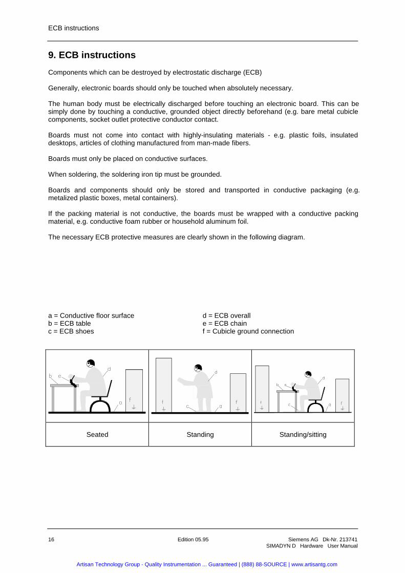
The necessary ECB protective measures are clearly shown in the following diagram.
a = Conductive floor surface d = ECB overallb = ECB table e = ECB chainc = ECB shoes f = Cubicle ground connection
Seated Standing Standing/sitting
Artisan Technology Group - Quality Instrumentation ... Guaranteed | (888) 88-SOURCE | www.artisantg.com
ECB instructions
Siemens AG Dk-Nr. 213741 Edition 05.95 17SIMADYN D Hardware User Manual
Artisan Technology Group - Quality Instrumentation ... Guaranteed | (888) 88-SOURCE | www.artisantg.com
ECB instructions
18 Edition 05.95 Siemens AG Dk-Nr. 213741SIMADYN D Hardware User Manual
Drives and Standard ProductsMotors and Drives Systems GroupPostfach 3269, D-91050 Erlangen
System-BasedTechnology
Artisan Technology Group - Quality Instrumentation ... Guaranteed | (888) 88-SOURCE | www.artisantg.com

Artisan Technology Group is your source for quality new and certified-used/pre-owned equipment
• FAST SHIPPING AND DELIVERY
• TENS OF THOUSANDS OF IN-STOCK ITEMS
• EQUIPMENT DEMOS
• HUNDREDS OF MANUFACTURERS SUPPORTED
• LEASING/MONTHLY RENTALS
• ITAR CERTIFIED SECURE ASSET SOLUTIONS
SERVICE CENTER REPAIRSExperienced engineers and technicians on staff at our full-service, in-house repair center
WE BUY USED EQUIPMENTSell your excess, underutilized, and idle used equipment We also offer credit for buy-backs and trade-inswww.artisantg.com/WeBuyEquipment
REMOTE INSPECTIONRemotely inspect equipment before purchasing with our interactive website at www.instraview.com
LOOKING FOR MORE INFORMATION? Visit us on the web at www.artisantg.com for more information on price quotations, drivers, technical specifications, manuals, and documentation
Contact us: (888) 88-SOURCE | [email protected] | www.artisantg.com
SMViewInstra