article iv standard specifications paving construction index iv.1 general€¦ · ·...
TRANSCRIPT

Revised 3/2018
ARTICLE IV
STANDARD SPECIFICATIONS
for
PAVING CONSTRUCTION
INDEX
IV.1 General
IV.2 Earth Work
IV.3 Mix Design
IV.4 Forms, Removing, Placing, and Finishing of Concrete
IV.5 Joints
IV.6 Protection and Opening to Traffic
IV.7 Tests
IV.8 Storm Sewer and Drainage Structures
IV.9 Sidewalks
IV.10 Miscellaneous
IV.11 Standard Drawings

Revised 3/2018 Page IV.1
ARTICLE IV
STANDARD SPECIFICATIONS
for
PAVING CONSTRUCTION
IV.1 GENERAL
A. The work covered by this Article IV of the specifications consists in furnishing all
labor, equipment, supplies and materials, and in performing all operations in
connection with the preparation of subgrade as required and in performing all
operations in the connection with the construction of air-entrained Portland cement
concrete pavement. The following recognized standards [State of Nebraska,
Department of Transportation 2017 Standard Specifications for Highway Construction
(NDOT), the American Water Works Association Standards (AWWA), American
Standards for Testing and Materials (ASTM), American Association of State Highway
and Transportation Officials (AASHTO), etc. or the latest revisions thereof] shall apply
except as hereinafter provided. All specifications included in this Article IV will
pertain except that special notations on the plans, in the Special Provisions or in the
General Provisions shall have precedence.
IV.2 EARTH WORK
A. All borrow material shall be approved by the Engineer before being placed.
B. Excavation of every description and of whatever substances encountered within the
limits of the project shall be performed to the lines and grades indicated on the
drawings. Except as otherwise permitted by the Engineer, all excavated areas shall be
excavated in such a manner as will afford adequate drainage. All suitable material
removed from the excavations shall be used, insofaras practicable, in the formation of
embankments, backfilling, and for such other purposes as directed by the Engineer.
Where material encountered within the limits of the work is considered unsuitable by
the Engineer, such materials shall be excavated below the grade shown on the
drawings or as directed by the Engineer, and replaced with suitable material. All
excavated materials which are considered unsuitable and any surplus of excavated
material which is not required for embankments shall be disposed of by the
Contractor as directed by the Engineer. In no case shall the Contractor be required to
haul excess excavation further than one half mile unless a supplementary agreement
covering the extra haul has been made. However, the Contractor may be required to
load such excess material into trucks furnished by the Owner, and to supply such
trucks as is mutually agreed would have been required to haul this material within the
one half mile limit, and this loading and hauling shall be considered as part of the
pavement bid price as outlined above.
Revised 3/2018 Page IV.2
C. Fill work shall consist of the construction of embankments by depositing, placing and
compacting materials of acceptable quality above the natural ground or other surface
in accordance with the lines, grades and cross sections shown on the plans, and as
required by the Engineer.
D. Before any fill is placed all clearing, tree removal, sod and top soil removal over the
entire area shall be performed as directed by the Engineer, and the entire area shall
then be rolled at least twice with a sheepsfoot roller.
E. Clearing shall consist of the removal and disposal of all obstructions such as
foundations, walls, fences, buildings, rubbish, etc., to a depth of at least 12 inches
below subgrade elevation. Sod within the area shall be removed to a depth of 6
inches.
F. Trees, except those designated to be saved and all stumps, shall be removed to a depth
of at least 18 inches below the subgrade elevation. All trees designated to be saved
shall be protected carefully during clearing and subsequent construction operations.
G. Topsoil shall be excavated and stockpiled as directed by the Engineer.
H. Material used as fill shall be free of debris, roots, organic matter, frozen matter, and
stone having any dimension greater than 2” in the top 6” of fill or greater than 4” in
other fill areas. Each layer of the fill material not to exceed 8 inches in loose depth
shall be disced sufficiently to break down oversized clods, to form a homogeneous
mixture of the different materials, to secure a uniform moisture content, and to insure
uniform density and proper compaction. Each layer shall be thoroughly compacted by
roller or vibratory equipment suitable for the type of embankment material.
I. In the event sufficient suitable fill material is not obtained within the limits of this
contract to provide all the embankment required, the Contractor shall furnish such
additional fill material borrow to complete the designated embankment. The cost of
furnishing this material shall be borne by the Contractor unless otherwise noted on the
plans or proposal form. Borrow material shall meet the same requirements as on-site
fill material and shall be approved by the Engineer.
J. The bottom of the excavation for the pavement or the top of the fill shall be known as
the pavement subgrade, and shall conform to the lines, grade and cross sections
shown on the plans.
K. All soft and yielding material and other portions of the subgrade which will not
compact readily when rolled or tamped, shall be removed as directed and replaced
with suitable material placed and compacted as specified herein.
L. All fill shall be compacted to a minimum of 90 percent of the maximum dry density
as determined by (AASHTO T99, ASTM D698) Standard Proctor. The top 6 inches
Revised 3/2018 Page IV.3
of fill in locations that coincide with the proposed or future proposed pavement and
the top 6" of the subgrade (in areas that do not require any fill) shall be compacted to
a minimum of 96 percent of the maximum density as determined by (AASHTO T99,
ASTM D698) Standard Proctor.
M. The Contractor shall bring all the fill material and the subgrade's moisture content to
not more than 4% above or 2% below the optimum content as determined by
(AASHTO T99, ASTM D698) Standard Proctor. If needed moisture shall be added,
the cost of which shall be subsidiary to other work performed.
N. Contractor shall hire an independent soil laboratory approved by the engineer to
establish the optimum moisture content, range, and maximum dry density before
beginning any tests for completion. Contractor shall hire a soil laboratory approved
by the engineer to perform all in-place compaction tests. All costs associated with
soil tests shall be the responsibility of the City. Any costs for retesting due to non-
passing results shall be the responsibility of the contractor.
O. When in-place density tests are performed, the tests shall be performed in accordance
with the procedures set forth in the following ASTM or latest version thereof:
ASTM D 2167 (Rubber Balloon Method)
ASTM D 1556 (Sand Cone Method)
ASTM D 6938 (Nuclear Method)
P. If the tests show non-compliance with the plans and specifications, the backfill shall
be removed, replaced, and retested by the Contractor without extra compensation and
at no extra cost to the Owner.
Q. The finished subgrade shall be maintained in a smooth and compacted condition until
the concrete has been placed. The mixer, ready-mix trucks, or other equipment shall
not operate between the forms unless permitted by the Engineer. If the Contractor is
permitted to operate trucks between the forms and the trucks cause rutting or
displacement of the subgrade material, either lighter loads shall be used or suitable
runways shall be provided. The Contractor shall re-roll or hand tamp the subgrade to
correct any ruts or other objectionable irregularities which may have been caused by
the trucking of materials.
R. The subgrade shall be finished in an acceptable condition for at least one half days
(1/2) progress in advance of the pavement construction at all times.
S. All excess concrete and debris shall be removed from the excavation behind the curb
line before backfilling. The backfill will be placed as indicated on the plans or graded
to form a uniform slope. The Contractor shall remove all dirt and debris from the
paving following backfill operations.

Revised 3/2018 Page IV.4
IV.3 MIX DESIGN
A. Mix Design. The Contractor shall, at his expense, have an approved independent
testing laboratory prepare the mix design using aggregated sampled from the
Contractor’s source for this project. The laboratory shall check the water reducing
admixture for compliance with ASTM-C-494, Type A regarding water reduction.
B. Preliminary Review. Reports covering the source and quality of concrete materials
and the concrete proportions proposed for the work shall be submitted to the
Engineer for review before any concrete is placed.
Alkali-Silica Reactivity Testing. Concrete shall be tested for alkali-silica reactivity
for each concrete mix utilized for the project. Alkali-silica reactivity for concrete
mixes shall be determined in accordance with ASTM C1567. The ASTM 1567
results will be considered current if the results are no more than 9 months old at the
time of submittal and will be no more than 12 months old when the last of the
concrete is placed.
Testing and reports for alkali-silica reactivity required for preliminary review shall
be made by an independent testing laboratory at the expense of the Contractor.
C. Portland Cement: All concrete for the project shall use Type IP cement in
accordance with the NDOT standard specifications. This includes concrete used for
retaining walls, storm sewer structures, sanitary sewer structures, and all concrete
surfacing.

Revised 3/2018 Page IV.5
D. Concrete shall be proportioned according to the following table:
Concrete Mixes (Cubic Yard Batch)
Class of
Concrete
Base
Cement
Type *
Portland
Cement
(Min.
lb/cy)
Pre-Blended
Class Fly
Ash* (Min.
lb/cy)
Total
Cementitious
Materials
(Min. lb/cy)
Total
Agg.
(Min.
lb/cy)
Total
Agg.
(Max.
lb/cy)
Course
Agg. (%)
(2)
Type of
Coarse
Agg.
Air
Content
(% Min.
– Max.)
(1)
Water/Cement
Ratio Max. (3)
Required
Strength
28 days
(Min.
psi)
47B (SLIP) 1PF 423 141 564 2850 3150 30+/- 3 Limestone 7.5 –
10.0
0.48 3500
47B (HAND) 1PF 423 141 564 2850 3150 30+/- 3 Limestone 6.0 –
8.5
0.48 3500
(1) As determined by ASTM C 138 or ASTM C 231.
(2) Coarse aggregate shall be limestone unless otherwise specified.
(3) The Contractor is responsible to adjust the water/cement ratio so that the concrete supplied achieves the required compressive
strength without exceeding the maximum water/cement ratio. The minimum water/cement ratio for any slip form concrete
pavement is 0.38.
(*) Mixes with Type 1PF and Class F fly ash designation are pre-blended or interground with Class F fly ash by the cement mill
producer at a rate of 25% +/- 2%, no additional Class F fly ash is added at the batch plant.

Revised 3/2018 Page IV.6
High Early Strength Concrete Pavement: The Contractor shall provide High Early
Strength Portland Cement Concrete for use at roadways and drives as indicated in the
plans or as directed by the Engineer. The Contractor shall submit to the Engineer for
approval, a proposed High Early Strength Concrete mix design, which will provide a
minimum concrete strength of 3,000 psi at 72 hours. Mix designs, which utilize
accelerators or admixtures containing calcium chloride, will not be considered. The
approved mix design shall be used at locations as directed and approved by the
Engineer to facilitate local traffic movement and access to businesses.
The Contractor, at his option, may elect to use the High Early Strength Concrete mix at
other locations to facilitate his operations, subject to approval of the Engineer.
Additional payment will not be made over and above the unit price bid for Concrete
Pavement for use of High Early Strength Concrete under these circumstances.
Payment for High Early Strength Portland Cement Concrete Pavement which is
authorized by the Engineer will be made in accordance with the unit price bid for the
appropriate pay items shown on the plans and bid proposal.
E. The minimum cement content shall not be less than 6.5 sacks per cubic yard of
concrete, and the maximum water content shall not exceed 6.0 gallons per sack of
cement, including the surface water on the aggregate. All water must be added to the
batch at the batch plant. No water shall be added from the transit mixer tank unless
permission is obtained from the Engineer.
F. A water reducing agent shall be used for all concrete furnished on this project. A set
retarding mixture shall be used only upon approval of the Engineer if weather
conditions warrant. All admixtures used shall be in liquid form, introduced into the
mix with an approved dispenser, and these admixture shall meet the appropriate
ASTM Spec. for Type A and D Admixtures.
G. The maximum allowable slump shall be 3 inches. Concrete that is rejected because of
excessive slump shall be removed completely from the project. Unloaded concrete
that is rejected shall not be retempered.
H. Compression test specimens shall be made in the field as required by the Engineer,
and in accordance with ASTM Designation C-31-49 when tested in accordance with
ASTM C-39 assumed minimum compressive strength shall be 7 day, 2,400 psi; 28
day, 3,500 psi.
IV.4 FORMS, REMOVING, PLACING, AND FINISHING OF CONCRETE
A. All forms used on this project shall meet the NDOT Specifications, and the placing of
concrete shall be done according to the NDOT Specifications, except as hereinafter
provided.
Revised 3/2018 Page IV.7
B. All concrete indicated to be removed adjacent to concrete to remain shall be sawcut
through its entire depth prior to removal.
C. The Engineer shall be given a minimum of 2 hours notice prior to the placement of
any concrete.
D. Concrete shall not be placed upon a soft, spongy or frozen subgrade or other
subgrade, the stability of which is, in the opinion of the Engineer, unsuitable for the
placement of concrete. The subgrade shall be in a moist condition at the time the
concrete is placed. It shall be thoroughly wetted a sufficient time in advance of the
placing of the concrete to insure that there will be no puddles or pockets of mud when
the concrete is placed, but shall not be allowed to dry out before the concrete is
placed.
E. All consolidating and finishing of concrete (including the method of curing it) on this
project shall be done according to the NDOT Specifications, except as hereinafter
provided.
F. The surface of the concrete pavement shall receive a wet burlap drag in order to give
it a finished texture. If approved by the Engineer, the driving lanes (only) may be
finished with a carpet drag, but the gutter line (2 feet in width) and curb face will still
require a wet burlap finish.
G. Integral curbs shall be required along the edges of all street pavement as indicated on
the plans, except at such locations as the Engineer may direct. Depressed curbs shall
be provided at all driveway entrances, and at such other locations as designated by the
Engineer.
H. The finished surface of the curb and gutter shall be checked by the use of the 10 foot
straight edge, and corrected if necessary. While the concrete is still plastic the
drainage at the gutter should be checked by pouring water at the gutter summit, and
observing its flow to the inlet. In order to prevent damage to the concrete surface, the
water should be poured onto a piece of burlap or curing paper.
I. All manholes, catch basins, or structures of a permanent nature encountered in the
areas to be paved shall be raised or lowered as the case may be, to the surface of the
new pavement.
J. A separate load ticket shall be made for each load of concrete showing truck number
and amounts of each of the separate materials. These tickets shall be furnished to the
inspector or Engineer on the job.

Revised 3/2018 Page IV.8
IV.5 JOINTS
A. When transverse contraction joints are to be formed by sawing, care must be taken to
saw the grooves soon after placing to prevent the formation of random cracks due to
contraction of any slab. All transverse joints shall be sawed at least 1/3 of the slab
depth. Any procedure for sawing joints that results in premature and uncontrolled
cracking shall be revised immediately by adjusting the time interval between the
placing of the concrete and the cutting of the joints.
B. Transverse dummy groove joints shall be formed by a groove or cleft in the top of the
slab of the dimensions shown on the plans. The groove made in the plastic concrete
by a suitable tooling device, shall extend vertically downward 1/3 of the slab depth
from the surface and shall be true to line.
C. Longitudinal construction joints (i.e., joints between construction lanes) shall be of
the dimensions shown on the plans. The keyway shall be constructed by placing a
deformed metal plate against the form when the first lane adjacent to the joint is
placed.
D. This metal plate shall be removed with the form. When placing the second slab, care
must be taken that no concrete is left to overhand the lip formed in the first slab by the
edging tool.
C. A thickened edge may be called for at the longitudinal construction joints. Such
construction shall conform to details shown on the plans.
D. All required joints shall be sealed with a joint sealer conforming to Section 1019 of
the NDOT Specifications 2017. Immediately prior to sealing of any joint, the joint
shall be sand blasted and blown to give the sealer a clean dry surface to bond to. The
sealing may be performed without the need for sand blasting if approved by the
Engineer, the joints are sealed the same day they are sawn, and the sawing is done
without the use of water.
E. Tiebars or tiebolts when shown on the plans shall be of deformed steel and of the
dimensions and at the spacing specified. Tiebars shall be firmly supported by
subgrade chairs. When drilling tiebars into existing concrete, the Contractor shall use
grout from the NDOT approved products list to secure the tiebars into the existing
pavement.
IV.6 PROTECTION AND OPENING TO TRAFFIC
A. Concrete shall be protected according to the NDOT Specifications 2017, except as
hereinafter provided.

Revised 3/2018 Page IV.9
B. The Contractor shall protect the pavement against all damage prior to final acceptance
of the work by the Owner. Traffic shall be excluded from the pavement by erecting
and maintaining barricades and signs until the concrete is at least 7 days old, or for a
longer period if so directed by the Engineer. The pavement shall not be used at any
time within this period for transporting or operating equipment.
C. As a construction expedient, the subgrade planer, concrete finishing machine, ready-
mix trucks, and similar equipment may be permitted to ride upon the previously
constructed slabs provided a compressive strength of 3000 psi has been attained, and
the equipment has rubber tired wheels to run on the finished slab. A rubber tired
trailer, pulled by hand, may be used to transport the forms as they are being removed,
providing the paving is more than 48 hours old.
D. When work is in progress on or adjacent to streets and highways the Contractor shall
erect warning signs as required by NDOT and according to the Manual on Uniform
Traffic Control Devices 2009 with revisions 1 and 2 and the Nebraska supplement
Edition.
E. The contractor shall provide the City of Norfolk a detailed traffic control plan prior to
the start of construction.
IV.7 TESTS
A. Compliance with the Specifications as to pavement thickness and compressive
strength shall be determined on a block basis. A block means the distance between
two intersecting streets provided that distance is not over 600 feet. Where the
distance is over 600 feet, the length shall be divided into parts not less than 250 feet,
nor more than 600 feet.
B. Compliance with the Specifications for thickness shall be based upon 4" diameter
concrete cores. If requested by the engineer core specimens shall be removed by the
Contractor in accordance with the procedures set forth in ASTM C-42 at no cost to
the Owner.
C. Longitudinally they shall be located at distances equal to 1/5, 1/2, and 4/5 of the
distance from the end of the block. Transversely they shall be located not more than
four feet from the center of a driving lane. (A driving lane is considered to be 11 feet
wide and the edge shall coincide with the center line of the pavement). For lengths of
pavement less than 40 feet, only one core is required for analysis. Lengths between
40 and 100 feet shall be accepted on the basis of two cores. Other locations may be
selected by the Engineer at his discretion.
D. Cores taken within a block shall be averaged to determine the thickness for that block.
Cores that exceed specified thickness, (T) plus 1/2 inch, shall be counted only as
specified thickness plus 1/2 inch. Cores that are less than specified thickness, (T)

Revised 3/2018 Page IV.10
minus 1/2 inch, shall indicate pavement that is unacceptable. If the core is deficient
by more than 1/2 inch, additional cores shall be taken to determine the extent of the
deficiency. These cores shall be taken at 10 foot intervals longitudinally on either
side of the deficient core. When cores indicate an acceptable thickness (T" to T"-
1/2"), the thickness of the pavement in the block shall be determined, omitting those
cores which define unacceptable pavement. If the average of the cores taken in a
block are not less than specified thickness minus 1/4 inch, the pavement shall be
considered to be of the specified thickness. Pavement which is between 1/4 to 1/2
inch deficient in thickness as determined by the average method, shall be accepted
only by the reduction in pay according to the following table:
Payment for Pavement
T - .25" = 100% of Bid Price
T - .30" = 93.0% of Bid Price
T - .35" = 86.5% of Bid Price
T - .40" = 80.5% of Bid Price
T - .45" = 75.0% of Bid Price
T - .50" = 70.0% of Bid Price
Less than T - .50" = 0%
E. Sampling and testing shall be performed by an independent certified testing
laboratory and shall be the responsibility of the Contractor. These costs will be paid
by the contractor. Number and type of tests to be determined by Engineer with a
minimum of one (1) air test, one (1) slump test, and one (1) set of test cylinders per
block (300’ of pavement) or 150 cubic yards for patch work. The cost of such tests
shall be included in the paving bid. The Contractor is responsible for supplying the
molds for the concrete test cylinders.
Samples for strength tests of each class of concrete shall be taken not less than once
for each days run nor less than once for each 150 cubic yards of concrete or for each
5,000 sq. feet of surface area placed. The samples for strength tests shall be taken in
accordance with “Method of Sampling Fresh Concrete” (ASTM C 172). Cylinders
for acceptance tests shall be molded and laboratory-cured in accordance with
“Method of Making and Curing Concrete Compressive and Flexural Strength Test
Specimens in the Field” (ASTM C 31) and tested in accordance with “Method of Test
for Compressive Strength of Molded Concrete Cylinders” (ASTM C39). Each
strength test result shall be the average of two cylinders from the same sample tested
at 28 days. One sample shall be taken and tested at 7 days.
When the frequency of testing provides less than five tests for a given class of
concrete, tests shall be made from at least five randomly selected batches or from
each batch if fewer than five are used. When the total quantity of a given class of
concrete is less than 50 cu. yards, the strength tests may be waived by the Engineer if,
in his judgment, adequate evidence of satisfactory strength is provided.

Revised 3/2018 Page IV.11
The strength level of the concrete will be considered satisfactory if the averages of all
sets of two consecutive strength test results equal or exceed the required strength and
no individual strength test result falls below the required strength by more than 500
psi, and complies with the requirements of ACI 318.
Strength tests of specimens cured under field conditions in accordance with Section 9
(c) of “Method of Making and Curing Concrete Compressive and Flexural Strength
Test Specimens in the Field” (ASTM C 31) may be required to check the adequacy of
curing and protection of the concrete in the structure. Such specimens shall be
molded at the same time and from the same samples as the laboratory-cured
acceptance test specimens. Procedures for protecting and curing the concrete shall be
improved when the strength of field-cured cylinders at the test age designated for
measuring strength is less than 85 percent of that of the companion laboratory-cured
cylinders. When the laboratory-cured cylinder strengths are appreciably higher than
strength, the field-cured cylinder strengths need not exceed strength by more than 500
psi even though the 85 percent criterion is not met.
If individual tests of laboratory-cured specimens produce strengths more than 500 psi
below strength or if tests of field-cured cylinders indicate deficiencies in protection
and curing, steps shall be taken to assure that load-carrying capacity of the structure is
not jeopardized. If the likelihood of low-strength concrete is confirmed and
computations indicate that the load carrying capacity may have been significantly
reduced, tests of cores drilled from the area in question shall be required in
accordance with “Method of Obtaining and Testing Drilled Cores and Sawed Beams
of Concrete” (ASTM C 42). Three cores shall be taken for each case of a cylinder
test more than 500 psi below strength. If the concrete in the structure will be dry
under service conditions, the cores shall be air dried temperature 60 to 80 F, relative
humidity less than 60 percent, for 7 days before test and shall be tested dry. If the
concrete in the structure will be more than superficially wet under service conditions,
the cores shall be immersed in water for at least 48 hours and tested wet.
Concrete in the area represented by the core tests will be considered structurally
adequate if the average of the three cores is equal to at least 85 percent of strength
and if no single core is less than 75 percent of strength.
To check testing accuracy, locations represented by erratic core strengths may be
retested. If these strength acceptance criteria are not met by the core tests, and if
structural adequacy remains in doubt, the Contractor shall provide load tests as
outlined in Chapter 20 (ACI 318) for the questionable portion of the structure, or take
other action appropriate to the circumstances. For any other concrete tests refer to
section IV.3.
Revised 3/2018 Page IV.12
F. Pavement which does not meet the minimum specifications for thickness or
strength shall be removed and replaced. Such replaced concrete shall be subject to
acceptance under the same plan as the entire block.
G. Ponding Water Testing and Correction: The Contractor is responsible for ensuring that
all pavement is constructed with positive drainage. Shallow areas of ponding water are
not permitted and the Contractor shall promptly repair any area found to pond water.
The Contractor shall flood the constructed street surfaces with water as directed by the
Engineer to demonstrate that the streets have positive drainage and no areas of ponded
water.
Any areas of water ponding that are discovered shall be corrected by performing the
necessary grinding of the concrete surface to provide positive drainage and eliminate
any ponded water. Grinding work shall gradually transition to existing pavement
surfaces and shall be complete to the satisfaction of the City and the Engineer.
Grinding over one-half inch in depth shall not be permitted. Any ponding area
requiring grinding in excess of one-half inch in depth to correct shall be corrected by
removal and replacement of the area of concrete pavement necessary to correct the
drainage. Concrete removal and replacement shall be to the nearest joint and to the
satisfaction of the Engineer.
IV.8 STORM SEWER AND DRAINAGE STRUCTURES
A. This section of the specification covers the installation of storm sewer pipe, drainage
structures, necessary excavation and backfilling and all other incidentals necessary for
proper construction of a drainage system. Recognized Standards (NDOT, ASTM,
AASHTO, etc.) as referred to herein, shall be construed to mean the latest adopted
standard, and shall form an integral part of this specification.
B. All materials used unless otherwise indicated on the plans, in the Special Provisions,
or on the Proposal shall conform to the applicable portion(s) of the following
requirements:
a. All reinforced concrete pipe (RCP) shall conform to the Specifications
for Reinforced Concrete Culvert, Storm Drain, and Sewer Pipe, ASTM
Designation, C-76, Class III tongue and groove pipe.
b. Corrugated metal pipe, culverts and flared end sections shall be of 16
gauge thickness, unless otherwise specified, and shall conform to the
requirements of AASTHO Standard Specification M 36. End sections shall
include suitable connections for fastening to pipes.
Revised 3/2018 Page IV.13
c. Grey Iron Casting shall conform to ASTM A-48, Class No. 35, and shall
be of the type and quality or an approved equal as follows:
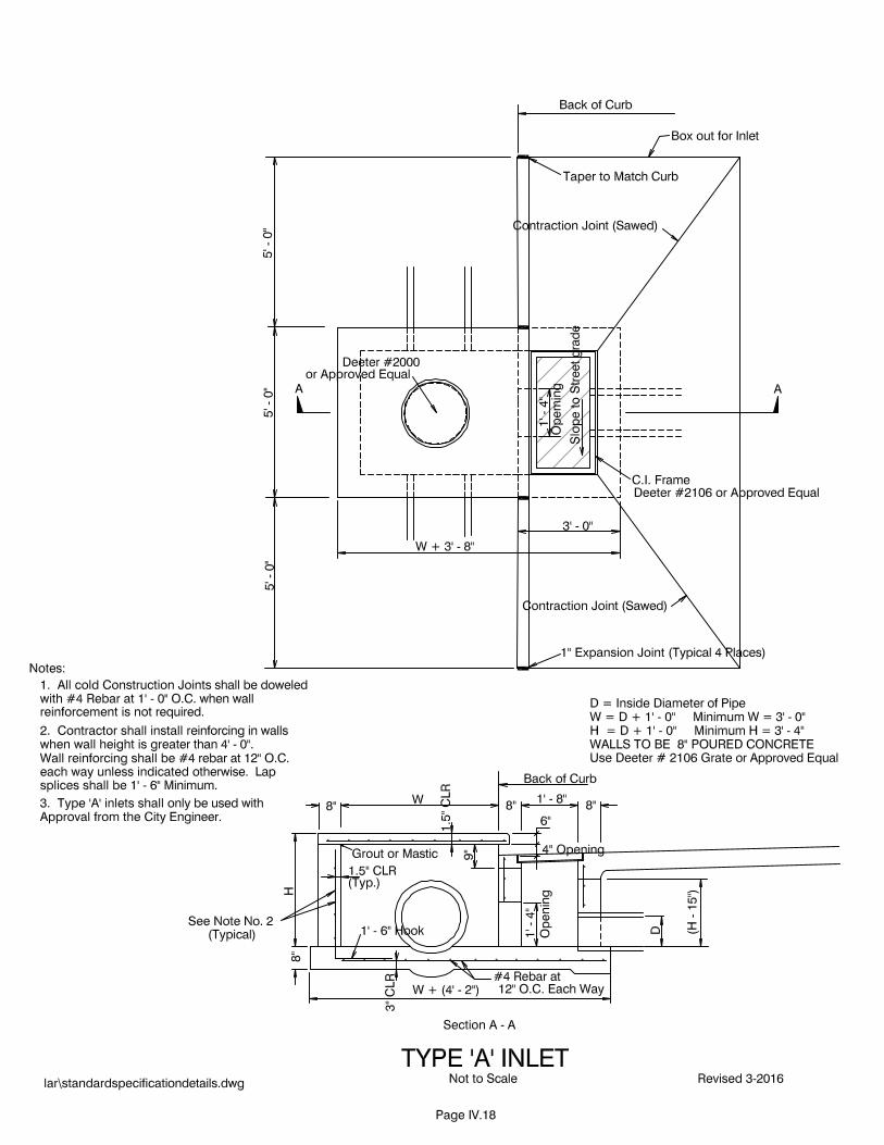
i. Manhole Ring and Cover not under traffic (Type A Inlets or Junction
Boxes) Deeter 2000.
ii. Manhole Ring and Cover under traffic (Junction Box) Deeter 1165.
iii. Manhole Ring and Cover Under traffic (Manhole) Deeter 1025.
iv. Frame and Grate under traffic (Type A or Type B Inlets) Deeter 2106.
C. All lifting holes in RCP shall be filled with concrete grout. Wire mesh shall be used
to prevent the grout from falling through the holes.
D. The Contractor shall perform all excavation of every description and of whatever
substances encountered, to the depths indicated on the drawings, and in accordance
with the lines and grades for the work to be given by the Engineer on such locations,
at such times, and only so far in advance of the work as may be required. All grading
in the vicinity of the trench shall be controlled to prevent surface ground water from
flowing into the trenches. Any water accumulated in the trenches shall be removed by
pumping or by other approved methods.
E. The Contractor shall proceed with caution in the excavation and preparation of the
trench so that the exact location of underground structures, both known and unknown,
may be determined, and he shall be held responsible for the repair of such structures
when broken or otherwise damaged because of carelessness on his part.
F. Whenever, in the opinion of the Engineer, it is necessary to explore and excavate to
determine the location of existing underground structures, the Contractor shall make
explorations and excavations for such purposes.
G. The bottom of the trench shall be accurately graded and shaped to provide uniform
bearing and support on undisturbed soil along its entire length. Bell holes, where
required, shall be excavated so that only the barrel of the pipe receives bearing
pressure from the trench bottom. This operation shall be done by hand by men skilled
in this type of work.
H. The materials excavated shall be laid compactly on the sides of the trench and kept
trimmed up so as to be of as little inconvenience as possible to public travel or the
adjoining tenants.
I. Pipe bedding consisting of washed river sand, or other material approved by the
Engineer, shall be provided for all storm sewer pipe, the price to be included in the
bid price for the pipe. Sand bedding shall extend the full width of the trench, and

Revised 3/2018 Page IV.14
shall extend upward from 3” below the bottom of the pipe to the centerline of the pipe
barrel. Backfill above centerline of pipe barrel shall be compacted earth.
J. Each pipe shall be inspected immediately before it is laid, and all defective or
damaged pipe shall be rejected. The Contractor shall assume full responsibility for
installing defective pipe, and will remove such pipe at his own expense when directed
to do so, and replace same with suitable material.
K. Pipe laying shall proceed up grade with the tongue ends of tongue-and-groove pipe
pointing in the direction of flow. The tongue ends of pipe shall be fully entered into
adjacent sections of pipe. Corrugated metal pipe shall be laid with the separate
sections joined firmly together, with the outside laps of circumferential joints pointing
upstream, and with longitudinal laps on the sides.
L. RCP joints shall be made with cold applied asphalt joint compound in accordance
with manufacturer’s recommendation. Prior to placing joint sealing material, the pipe
ends shall be thoroughly cleaned to provide direct contact between pipe and sealer.
The joint shall be completely filled and then pointed and smoothed from the inside.
This joint material shall be "Kalkite 340", "Plastice" or approved equal.
M. The Contractor shall backfill from the bottom of the trench to the center line of the
pipe barrel with sand, and the balance of the trench shall be backfilled using suitable
material from the excavation of the trench. Material suitable for use as backfill shall
be free of debris, roots, organic matter, frozen matter, and stone having dimensions
greater than 2” in the top 12” of backfill or greater than 4” elsewhere. All backfill
must be compacted to a minimum of 90 percent of the maximum dry density as
determined by (AASHTO T99, ASTM D698) Standard Proctor. The top 12 inches of
backfill in locations under existing or future pavement shall be compacted to a
minimum of 96 percent of the maximum density as determined by (AASHTO T99,
ASTM D698) Standard Proctor.
N. Under existing or future pavements the Engineer may require that the backfill shall be
placed and compacted in lifts of eight (8") inches maximum loose thickness.
O. The Contractor shall bring all backfill material to not more than 4% above or 2%
below the optimum moisture content before backfilling as determined by (AASHTO
T99, ASTM D698) Standard Proctor.
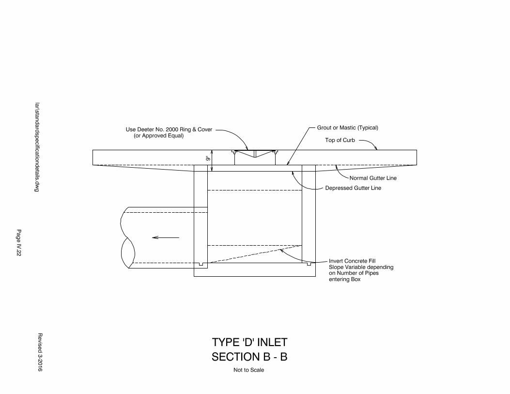
P. The Contractor shall construct new sewer inlets, and manholes of the types, and in the
locations shown on the plans or where directed by the Engineer. Inlets and junction
boxes shall be constructed of 8" poured in place concrete. The floor of a manhole or
inlet shall be smooth and slope towards the channel at 1 1/2 inches per foot plus or
minus 1/2 inch per foot. The invert of the channels shall be smooth and semi-circular
in shape and changes in direction of flow shall be made in a smooth long radius
curve.

Revised 3/2018 Page IV.15
Q. All concrete shall be worked into place and consolidated by internal or external
vibrators, or types acceptable to the Engineer. External vibrators of approved type
may also be used in addition to internal vibrators. Before placing any concrete, all
surfaces upon which or against which the concrete is to be placed shall be cleaned of
all mud and debris. Concrete shall be NDOT Class 47-B unless stated otherwise on
plan or special provision.
R. An approved plastic bituminous compound may be used in making the joints in
precast manhole rings in locations where ground water is not a problem. This
material shall be "Tufflex", "Plastice", or other approved equal.
S. Connection to existing storm sewer will be made as shown on the drawings. All
concrete work, cutting, and shaping will be done in a workmanlike manner to the
satisfaction of the Engineer.
T. Concrete for headwall construction shall consist of form construction and the
handling, placing, curing, and finishing of concrete for headwalls in accordance with
these specifications and in conformity with the lines, grades, dimensions, and designs
shown in the plans, and/or as directed by the Engineer.
IV.9 SIDEWALKS
A. Sidewalks shall be constructed according to the most current ADA standards.
B. Unless called out specifically on the plans, no running/longitudinal slope shall
exceed 5.0% without approval of the Engineer, with the exception of curb ramps.
C. All areas at the top of curb ramps or wherever the 5.0% running slope is exceeded,
shall have a flat area as required per current ADA standards. Flat is defined as a
slope that does not exceed 2.0% in any direction. Positive drainage is required at
all sidewalks, including flat areas.
D. All sidewalk cross slopes shall be less than 2.0% including across driveways.
E. Forms shall be set at 0.5% below maximum allowable slopes to allow for variances
during construction operations.
F. Sand and gravel mixture may be substituted for Type 47B aggregate for sidewalks
only. 47B shall still be utilized where sidewalks cross driveways or other drivable
surfaces.
G. The Contractor shall space contraction joints in sidewalks equal to the width of the
sidewalk.

Revised 3/2018 Page IV.16
H. Detectable warning panels shall be preformed and embedded into the concrete
sidewalk. They shall be black in color and from the NDOT approved products list.
IV.10 MISCELLANEOUS
A. The Engineer's office shall be given 48 hours notice before any construction begins,
and 3 working days notice for any work requiring staking by the Owner.
B. All sites to be used for proportioning plants, mixing plants, or storage of materials or
equipment, shall be only those having the approval of the Building Inspector if the
site is within the City's two-mile zoning jurisdiction.

Revised 3/2018 Page IV.17
IV.11 STANDARD DRAWINGS
Type ‘A’ Inlet...........................................................Page IV.18
Type ‘B’ Inlet...........................................................Page IV.19
Type ‘D’ Inlet – Standard …………………………Page IV.20
Type ‘D’ Inlet – Section A-A…………………..…..Page IV.21
Type ‘D’ Inlet – Section B-B…………………..…..Page IV.22
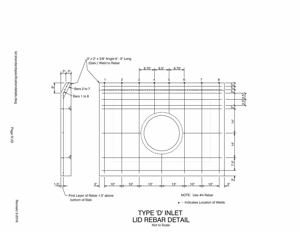
Type ‘D’ Inlet – Rebar Detail …………………..…Page IV.23
Storm Sewer Manhole Detail and
Concrete Manhole Lid Detail ……………..……... Page IV.24
Typical Transverse Section for 27’ Paving &
Integral Curb Detail ………....................................Page IV.25
Typical Transverse Sections for
31’ & 36” Paving......................................................Page IV.26
Longitudinal Joints, Longitudinal Construction
Joint & Concrete Header …………...………….…. Page IV.27
Expansion Joint w/
Assembly Plan...........................................................Page IV.28
Contraction Joint Sawed, Transverse Construction
Joint & Special Construction Joint ...........................Page IV.29
Typical Pedestrian Ramp Detail …………………...Page IV.30
Storm Sewer - Water Main Crossings…....................Page IV.31