article 314 outlet, device, pull, and junction boxes
TRANSCRIPT

ARTICLE 314 Outlet, Device, Pull, and Junction Boxes; Conduit Bodies; Fittings; and Handhole Enclosures Part I. Scope and General 314.1 Scope. This article covers the installation and use of all boxes and conduit bodies used as outlet, device, junction, or pull boxes, depending on their use, and handhole enclosures. Cast metal, sheet metal, nonmetallic, and other boxes such as FS, FD, and larger boxes are not classified as conduit bodies. This article also includes installation requirements for fittings used to join raceways and to connect raceways and cables to boxes and conduit bodies.
314.2 Round Boxes. Round boxes shall not be used where conduits or connectors requiring the use of locknuts or bushings are to be connected to the side of the box.
314.3 Nonmetallic Boxes. Nonmetallic boxes shall be permitted only with open wiring on insulators, concealed knob-and-tube wiring, cabled wiring methods with entirely nonmetallic sheaths, flexible cords, and nonmetallic raceways.
Exception No. 1: Where internal bonding means are provided between all entries, nonmetallic boxes shall be permitted to be used with metal raceways or metal-armored cables.
Exception No. 2: Where integral bonding means with a provision for attaching an equipment bonding jumper inside the box are provided between all threaded entries in nonmetallic boxes listed for the purpose, nonmetallic boxes shall be permitted to be used with metal raceways or metal-armored cables.
314.4 Metal Boxes. Metal boxes shall be grounded and bonded in accordance with Parts I, IV, V, VI, VII, and X of Article 250 as applicable, except as permitted in 250.112(I).
Part II. Installation 314.15 Damp or Wet Locations. In damp or wet locations, boxes, conduit bodies, outlet box hoods, and fittings shall be placed or equipped so as to prevent moisture from entering or accumulating within the box, conduit body, or fitting. Boxes, conduit bodies, outlet box hoods, and fittings installed in wet locations shall be listed for use in wet locations. Approved drainage openings not smaller than 3 mm (1∕ 8 in.) and not larger than 6 mm (1∕ 4 in.) in diameter shall be permitted to be installed in the field in boxes or conduit bodies listed for use in damp or wet locations. For installation of listed drain fittings, larger openings are permitted to be installed in the field in accordance with manufacturer’s instructions.
Informational Note No. 1: For boxes in floors, see 314.27(B).
Informational Note No. 2: For protection against corrosion, see 300.6.
314.16 Number of Conductors in Outlet, Device, and Junction Boxes, and Conduit Bodies. Boxes and conduit bodies shall be of an approved size to provide free space for all enclosed conductors. In no case shall the volume of the box, as calculated in 314.16(A), be less than the fill calculation as calculated in 314.16(B). The minimum volume for conduit bodies shall be as calculated in 314.16(C).
The provisions of this section shall not apply to terminal housings supplied with motors or generators.
Informational Note: For volume requirements of motor or generator terminal housings, see 430.12.
Boxes and conduit bodies enclosing conductors 4 AWG or larger shall also comply with the provisions of 314.28. Outlet and device boxes shall also comply with 314.24.

314.16(B) Box Fill Calculations. The volumes in paragraphs 314.16(B)(1) through (B)(5), as applicable, shall be added together. No allowance shall be required for small fittings such as locknuts and bushings. Each space within a box installed with a barrier shall be calculated separately.
314.16(B)(1) Conductor Fill. Each conductor that originates outside the box and terminates or is spliced within the box shall be counted once, and each conductor that passes through the box without splice or termination shall be counted once. Each loop or coil of unbroken conductor not less than twice the minimum length required for free conductors in 300.14 shall be counted twice. The conductor fill shall be calculated using Table 314.16(B). A conductor, no part of which leaves the box, shall not be counted.
Exception: An equipment grounding conductor or conductors or not over four fixture wires smaller than 14 AWG, or both, shall be permitted to be omitted from the calculations where they enter a box from a domed luminaire or similar canopy and terminate within that box.
314.16(B)(2) Clamp Fill. Where one or more internal cable clamps, whether factory or field supplied, are present in the box, a single volume allowance in accordance with Table 314.16(B) shall be made based on the largest conductor present in the box. No allowance shall be required for a cable connector with its clamping mechanism outside the box.
A clamp assembly that incorporates a cable termination for the cable conductors shall be listed and marked for use with specific nonmetallic boxes. Conductors that originate within the clamp assembly shall be included in conductor fill calculations covered in 314.16(B)(1) as though they entered from outside the box. The clamp assembly shall not require a fill allowance, but the volume of the portion of the assembly that remains within the box after installation shall be excluded from the box volume as marked in 314.16(A)(2).
314.16(B)(3) Support Fittings Fill. Where one or more luminaire studs or hickeys are present in the box, a single volume allowance in accordance with Table 314.16(B) shall be made for each type of fitting based on the largest conductor present in the box.
314.16(B)(4) Device or Equipment Fill. For each yoke or strap containing one or more devices or equipment, a double volume allowance in accordance with Table 314.16(B) shall be made for each yoke or strap based on the largest conductor connected to a device(s) or equipment supported by that yoke or strap. A device or utilization equipment wider than a single 50 mm (2 in.) device box as described in Table 314.16(A) shall have double volume allowances provided for each gang required for mounting.
Table 314.16(B) Volume Allowance Required per Conductor
Size of Conductor (AWG)
Free Space Within Box for Each
Conductor
cm3 in.3
18 24.6 1.50
16 28.7 1.75
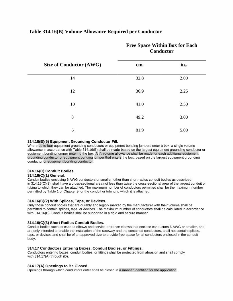
Table 314.16(B) Volume Allowance Required per Conductor
Size of Conductor (AWG)
Free Space Within Box for Each
Conductor
cm3 in.3
14 32.8 2.00
12 36.9 2.25
10 41.0 2.50
8 49.2 3.00
6 81.9 5.00
314.16(B)(5) Equipment Grounding Conductor Fill. Where up to four equipment grounding conductors or equipment bonding jumpers enter a box, a single volume allowance in accordance with Table 314.16(B) shall be made based on the largest equipment grounding conductor or equipment bonding jumper entering the box. A 1∕ 4 volume allowance shall be made for each additional equipment grounding conductor or equipment bonding jumper that enters the box, based on the largest equipment grounding conductor or equipment bonding conductor.
314.16(C) Conduit Bodies. 314.16(C)(1) General. Conduit bodies enclosing 6 AWG conductors or smaller, other than short-radius conduit bodies as described in 314.16(C)(3), shall have a cross-sectional area not less than twice the cross-sectional area of the largest conduit or tubing to which they can be attached. The maximum number of conductors permitted shall be the maximum number permitted by Table 1 of Chapter 9 for the conduit or tubing to which it is attached.
314.16(C)(2) With Splices, Taps, or Devices. Only those conduit bodies that are durably and legibly marked by the manufacturer with their volume shall be permitted to contain splices, taps, or devices. The maximum number of conductors shall be calculated in accordance with 314.16(B). Conduit bodies shall be supported in a rigid and secure manner.
314.16(C)(3) Short Radius Conduit Bodies. Conduit bodies such as capped elbows and service-entrance elbows that enclose conductors 6 AWG or smaller, and are only intended to enable the installation of the raceway and the contained conductors, shall not contain splices, taps, or devices and shall be of an approved size to provide free space for all conductors enclosed in the conduit body.
314.17 Conductors Entering Boxes, Conduit Bodies, or Fittings. Conductors entering boxes, conduit bodies, or fittings shall be protected from abrasion and shall comply with 314.17(A) through (D).
314.17(A) Openings to Be Closed. Openings through which conductors enter shall be closed in a manner identified for the application.

314.17(B) Boxes and Conduit Bodies. The installation of the conductors in boxes and conduit bodies shall comply with 314.17(B)(1) through (B)(4).
314.17(B)(1) Conductors Entering Through Individual Holes or Through Flexible Tubing. For messenger-supported wiring, open wiring on insulators, or concealed knob-and-tube wiring, the conductors shall enter the box through individual holes. In installations where metal boxes or conduit bodies are used with conductors unprotected by flexible tubing, the individual openings shall be provided with insulating bushings. Where flexible tubing is used to enclose the conductors, the tubing shall extend from the last insulating support to not less than 6 mm (1∕ 4 in.) inside the box or conduit body and beyond any cable clamp. The wiring method shall be secured to the box or conduit body.
314.17(B)(2) Conductors Entering Through Cable Clamps. Where cable assemblies with nonmetallic sheathes are used, the sheath shall extend not less than 6 mm (1∕ 4 in.) inside the box and beyond any cable clamp. Except as provided in 300.15(C), the wiring method shall be secured to the box or conduit body.
Exception: Where nonmetallic-sheathed cable is used with single gang nonmetallic boxes not larger than a nominal size 57 mm × 100 mm (21∕ 4 in. × 4 in.) mounted in walls or ceilings, and where the cable is fastened within 200 mm (8 in.) of the box measured along the sheath and where the sheath extends through a cable knockout not less than 6 mm (1∕ 4 in.), securing the cable to the box shall not be required. Multiple cable entries shall be permitted in a single cable knockout opening.
314.17(B)(3) Conductors Entering Through Raceways. Where the raceway is complete between boxes, conduit bodies, or both and encloses individual conductors or nonmetallic cable assemblies or both, the conductors or cable assemblies shall not be required to be additionally secured. Where raceways enclose cable assemblies as provided in 300.15(C), the cable assembly shall not be required to be additionally secured within the box or conduit body.
314.17(B)(4) Temperature Limitation. Nonmetallic boxes and conduit bodies shall be suitable for the lowest temperature-rated conductor entering the box or conduit body.
314.17(C) Conductors 4 AWG or Larger. Installation shall comply with 300.4(G).
Informational Note: See 110.12(A) for requirements on closing unused cable and raceway knockout openings.
314.19 Boxes Enclosing Flush Devices or Flush Equipment. Boxes used to enclose flush devices or flush equipment shall be of such design that the devices or equipment will be completely enclosed on the back and sides, and substantial support for the devices or equipment will be provided. Screws for supporting the box shall not also be used to attach a device or equipment.
314.20 Flush-Mounted Installations. Installations within or behind a surface of concrete, tile, gypsum, plaster, or other noncombustible material, including boxes employing a flush-type cover or faceplate, shall be made so that the front edge of the box, plaster ring, extension ring, or listed extender will not be set back of the finished surface more than 6 mm (1∕ 4 in.).
Installations within a surface of wood or other combustible surface material, boxes, plaster rings, extension rings, or listed extenders shall extend to the finished surface or project therefrom.
314.21 Repairing Noncombustible Surfaces. Noncombustible surfaces that are broken or incomplete around boxes employing a flush-type cover or faceplate shall be repaired so there will be no gaps or open spaces greater than 3 mm (1∕ 8 in.) at the edge of the box.
314.22 Surface Extensions.

Surface extensions shall be made by mounting and mechanically securing an extension ring over the box. Equipment grounding shall be in accordance with Part VI of Article 250.
Exception: A surface extension shall be permitted to be made from the cover of a box where the cover is designed so it is unlikely to fall off or be removed if its securing means becomes loose. The wiring method shall be flexible for an approved length that permits removal of the cover and provides access to the box interior and shall be arranged so that any grounding continuity is independent of the connection between the box and cover.
314.23 Supports. Enclosures within the scope of this article shall be supported in accordance with one or more of the provisions in 314.23(A) through (H).
314.23(A) Surface Mounting. An enclosure mounted on a building or other surface shall be rigidly and securely fastened in place. If the surface does not provide rigid and secure support, additional support in accordance with other provisions of this section shall be provided.
314.23(B) Structural Mounting. An enclosure supported from a structural member or from grade shall be rigidly supported either directly or by using a metal, polymeric, or wood brace.
314.23(B)(1) Nails and Screws. Nails and screws, where used as a fastening means, shall secure boxes by using brackets on the outside of the enclosure, or by using mounting holes in the back or in one or more sides of the enclosure, or they shall pass through the interior within 6 mm (1∕ 4 in.) of the back or ends of the enclosure. Screws shall not be permitted to pass through the box unless exposed threads in the box are protected using approved means to avoid abrasion of conductor insulation. Mounting holes made in the field shall be approved.
314.23(B)(2) Braces. Metal braces shall be protected against corrosion and formed from metal that is not less than 0.51 mm (0.020 in.) thick uncoated. Wood braces shall have a cross section not less than nominal 25 mm × 50 mm (1 in. × 2 in.). Wood braces in wet locations shall be treated for the conditions. Polymeric braces shall be identified as being suitable for the use.
314.23(C) Mounting in Finished Surfaces. An enclosure mounted in a finished surface shall be rigidly secured thereto by clamps, anchors, or fittings identified for the application.
314.23(D) Suspended Ceilings. An enclosure mounted to structural or supporting elements of a suspended ceiling shall be not more than 1650 cm3 (100 in.3) in size and shall be securely fastened in place in accordance with either 314.23(D)(1) or (D)(2).
314.23(D)(1) Framing Members. An enclosure shall be fastened to the framing members by mechanical means such as bolts, screws, or rivets, or by the use of clips or other securing means identified for use with the type of ceiling framing member(s) and enclosure(s) employed. The framing members shall be supported in an approved manner and securely fastened to each other and to the building structure.
314.23(D)(2) Support Wires. The installation shall comply with 300.11(A). The enclosure shall be secured, using identified methods, to ceiling support wire(s), including any additional support wire(s) installed for ceiling support. Support wire(s) used for enclosure support shall be fastened at each end so as to be taut within the ceiling cavity.
314.23(E) Raceway-Supported Enclosure, Without Devices, Luminaires, or Lampholders. An enclosure that does not contain a device(s), other than splicing devices, or supports a luminaire(s), a lampholder, or other equipment and is supported by entering raceways shall not exceed 1650 cm3 (100 in.3) in size. It shall have threaded entries or identified hubs. It shall be supported by two or more conduits threaded wrenchtight into the

enclosure or hubs. Each conduit shall be secured within 900 mm (3 ft) of the enclosure, or within 450 mm (18 in.) of the enclosure if all conduit entries are on the same side.
Exception: The following wiring methods shall be permitted to support a conduit body of any size, including a conduit body constructed with only one conduit entry, provided that the trade size of the conduit body is not larger than the largest trade size of the conduit or tubing:
(1) Intermediate metal conduit, Type IMC
(2) Rigid metal conduit, Type RMC
(3) Rigid polyvinyl chloride conduit, Type PVC
(4) Reinforced thermosetting resin conduit, Type RTRC
(5) Electrical metallic tubing, Type EMT
314.23(F) Raceway-Supported Enclosures, with Devices, Luminaires, or Lampholders. An enclosure that contains a device(s), other than splicing devices, or supports a luminaire(s), a lampholder, or other equipment and is supported by entering raceways shall not exceed 1650 cm3 (100 in.3) in size. It shall have threaded entries or identified hubs. It shall be supported by two or more conduits threaded wrenchtight into the enclosure or hubs. Each conduit shall be secured within 450 mm (18 in.) of the enclosure.
Exception No. 1: Rigid metal or intermediate metal conduit shall be permitted to support a conduit body of any size, including a conduit body constructed with only one conduit entry, provided the trade size of the conduit body is not larger than the largest trade size of the conduit.
Exception No. 2: An unbroken length(s) of rigid or intermediate metal conduit shall be permitted to support a box used for luminaire or lampholder support, or to support a wiring enclosure that is an integral part of a luminaire and used in lieu of a box in accordance with 300.15(B), where all of the following conditions are met:
(1) The conduit is securely fastened at a point so that the length of conduit beyond the last point of conduit support does not exceed 900 mm (3 ft).
(2) The unbroken conduit length before the last point of conduit support is 300 mm (12 in.) or greater, and that portion of the conduit is securely fastened at some point not less than 300 mm (12 in.) from its last point of support.
(3) Where accessible to unqualified persons, the luminaire or lampholder, measured to its lowest point, is at least 2.5 m (8 ft) above grade or standing area and at least 900 mm (3 ft) measured horizontally to the 2.5 m (8 ft) elevation from windows, doors, porches, fire escapes, or similar locations.
(4) A luminaire supported by a single conduit does not exceed 300 mm (12 in.) in any direction from the point of conduit entry.
(5) The weight supported by any single conduit does not exceed 9 kg (20 lb).
(6) At the luminaire or lampholder end, the conduit(s) is threaded wrenchtight into the box, conduit body, integral wiring enclosure, or identified hubs. Where a box or conduit body is used for support, the luminaire shall be secured directly to the box or conduit body, or through a threaded conduit nipple not over 75 mm (3 in.) long.
314.23(G) Enclosures in Concrete or Masonry. An enclosure supported by embedment shall be identified as suitably protected from corrosion and securely embedded in concrete or masonry.

314.23(H) Pendant Boxes. An enclosure supported by a pendant shall comply with 314.23(H)(1) or (H)(2).
314.23(H)(1) Flexible Cord. A box shall be supported from a multiconductor cord or cable in an approved manner that protects the conductors against strain, such as a strain-relief connector threaded into a box with a hub.
314.23(H)(2) Conduit. A box supporting lampholders or luminaires, or wiring enclosures within luminaires used in lieu of boxes in accordance with 300.15(B), shall be supported by rigid or intermediate metal conduit stems. For stems longer than 450 mm (18 in.), the stems shall be connected to the wiring system with listed swivel hangers suitable for the location. At the luminaire end, the conduit(s) shall be threaded wrenchtight into the box, wiring enclosure, or identified hubs.
Where supported by only a single conduit, the threaded joints shall be prevented from loosening by the use of set-screws or other effective means, or the luminaire, at any point, shall be at least 2.5 m (8 ft) above grade or standing area and at least 900 mm (3 ft) measured horizontally to the 2.5 m (8 ft) elevation from windows, doors, porches, fire escapes, or similar locations. A luminaire supported by a single conduit shall not exceed 300 mm (12 in.) in any horizontal direction from the point of conduit entry.
314.24 Depth of Boxes. Outlet and device boxes shall have an approved depth to allow equipment installed within them to be mounted properly and without likelihood of damage to conductors within the box.
314.24(A) Outlet Boxes Without Enclosed Devices or Utilization Equipment. Outlet boxes that do not enclose devices or utilization equipment shall have a minimum internal depth of 12.7 mm (1∕ 2 in.).
314.24(B) Outlet and Device Boxes with Enclosed Devices or Utilization Equipment. Outlet and device boxes that enclose devices or utilization equipment shall have a minimum internal depth that accommodates the rearward projection of the equipment and the size of the conductors that supply the equipment. The internal depth shall include, where used, that of any extension boxes, plaster rings, or raised covers. The internal depth shall comply with all applicable provisions of 314.24(B)(1) through (B)(5).
314.24(B)(1) Large Equipment. Boxes that enclose devices or utilization equipment that projects more than 48 mm (17∕ 8 in.) rearward from the mounting plane of the box shall have a depth that is not less than the depth of the equipment plus 6 mm (1∕ 4 in.).
314.24(B)(2) Conductors Larger Than 4 AWG. Boxes that enclose devices or utilization equipment supplied by conductors larger than 4 AWG shall be identified for their specific function.
Exception to (2): Devices or utilization equipment supplied by conductors larger than 4 AWG shall be permitted to be mounted on or in junction and pull boxes larger than 1650 cm3 (100 in.3) if the spacing at the terminals meets the requirements of 312.6.
314.24(B)(3) Conductors 8, 6, or 4 AWG. Boxes that enclose devices or utilization equipment supplied by 8, 6, or 4 AWG conductors shall have an internal depth that is not less than 52.4 mm (21∕ 16 in.).
314.24(B)(4) Conductors 12 or 10 AWG. Boxes that enclose devices or utilization equipment supplied by 12 or 10 AWG conductors shall have an internal depth that is not less than 30.2 mm (13∕ 16 in.). Where the equipment projects rearward from the mounting plane of the box by more than 25 mm (1 in.), the box shall have a depth not less than that of the equipment plus 6 mm (1∕ 4 in.).
314.24(B)(5) Conductors 14 AWG and Smaller.

Boxes that enclose devices or utilization equipment supplied by 14 AWG or smaller conductors shall have a depth that is not less than 23.8 mm (15∕ 16 in.).
Exception to (1) through (5): Devices or utilization equipment that is listed to be installed with specified boxes shall be permitted.
314.25 Covers and Canopies. In completed installations, each box shall have a cover, faceplate, lampholder, or luminaire canopy, except where the installation complies with 410.24(B). Screws used for the purpose of attaching covers, or other equipment, to the box shall be either machine screws matching the thread gauge and size that is integral to the box or shall be in accordance with the manufacturer’s instructions.
314.25(A) Nonmetallic or Metal Covers and Plates. Nonmetallic or metal covers and plates shall be permitted. Where metal covers or plates are used, they shall comply with the grounding requirements of 250.110.
Informational Note: For additional grounding requirements, see 410.42 for metal luminaire canopies, and 404.12 and 406.6(B) for metal faceplates.
314.25(B) Exposed Combustible Wall or Ceiling Finish. Where a luminaire canopy or pan is used, any combustible wall or ceiling finish exposed between the edge of the canopy or pan and the outlet box shall be covered with noncombustible material if required by 410.23.
314.25(C) Flexible Cord Pendants. Covers of outlet boxes and conduit bodies having holes through which flexible cord pendants pass shall be provided with identified bushings or shall have smooth, well-rounded surfaces on which the cords may bear. So-called hard rubber or composition bushings shall not be used.
314.27 Outlet Boxes. 314.27(A) Boxes at Luminaire or Lampholder Outlets. Outlet boxes or fittings designed for the support of luminaires and lampholders, and installed as required by 314.23, shall be permitted to support a luminaire or lampholder.
314.27(A)(1) Vertical Surface Outlets. Boxes used at luminaire or lampholder outlets in or on a vertical surface shall be identified and marked on the interior of the box to indicate the maximum weight of the luminaire that is permitted to be supported by the box if other than 23 kg (50 lb).
Exception: A vertically mounted luminaire or lampholder weighing not more than 3 kg (6 lb) shall be permitted to be supported on other boxes or plaster rings that are secured to other boxes, provided that the luminaire or its supporting yoke, or the lampholder, is secured to the box with no fewer than two No. 6 or larger screws.
314.27(A)(2) Ceiling Outlets. At every outlet used exclusively for lighting, the box shall be designed or installed so that a luminaire or lampholder may be attached. Boxes shall be required to support a luminaire weighing a minimum of 23 kg (50 lb). A luminaire that weighs more than 23 kg (50 lb) shall be supported independently of the outlet box, unless the outlet box is listed for not less than the weight to be supported. The interior of the box shall be marked by the manufacturer to indicate the maximum weight the box shall be permitted to support.
314.27(B) Floor Boxes. Boxes listed specifically for this application shall be used for receptacles located in the floor.
Exception: Where the authority having jurisdiction judges them free from likely exposure to physical damage, moisture, and dirt, boxes located in elevated floors of show windows and similar locations shall be permitted to be other than those listed for floor applications. Receptacles and covers shall be listed as an assembly for this type of location.
314.27(C) Boxes at Ceiling-Suspended (Paddle) Fan Outlets. Outlet boxes or outlet box systems used as the sole support of a ceiling-suspended (paddle) fan shall be listed, shall be marked by their manufacturer as suitable for this purpose, and shall not support ceiling-suspended (paddle) fans that weigh more than 32 kg (70 lb). For outlet boxes or outlet box systems designed to support ceiling-suspended (paddle) fans that weigh more than 16 kg (35 lb), the required marking shall include the maximum weight to be supported.
Outlet boxes mounted in the ceilings of habitable rooms of dwelling occupancies in a location acceptable for the installation of a ceiling-suspended (paddle) fan shall comply with one of the following:
(1) Listed for the sole support of ceiling-suspended (paddle) fans
(2) An outlet box complying with the applicable requirements of 314.27 and providing access to structural framing capable of supporting of a ceiling-suspended (paddle) fan bracket or equivalent
314.27(D) Utilization Equipment. Boxes used for the support of utilization equipment other than ceiling-suspended (paddle) fans shall meet the requirements of 314.27(A) for the support of a luminaire that is the same size and weight.
Exception: Utilization equipment weighing not more than 3 kg (6 lb) shall be permitted to be supported on other boxes or plaster rings that are secured to other boxes, provided the equipment or its supporting yoke is secured to the box with no fewer than two No. 6 or larger screws.
314.27(E) Separable Attachment Fittings. Outlet boxes required in 314.27 shall be permitted to support listed locking support and mounting receptacles used in combination with compatible attachment fittings. The combination shall be identified for the support of equipment within the weight and mounting orientation limits of the listing. Where the supporting receptacle is installed within a box, it shall be included in the fill calculation covered in 314.16(B)(4).
314.28 Pull and Junction Boxes and Conduit Bodies. Boxes and conduit bodies used as pull or junction boxes shall comply with 314.28(A) through (E).
Exception: Terminal housings supplied with motors shall comply with the provisions of 430.12.
314.28(A) Minimum Size. For raceways containing conductors of 4 AWG or larger that are required to be insulated, and for cables containing conductors of 4 AWG or larger, the minimum dimensions of pull or junction boxes installed in a raceway or cable run shall comply with 314.28(A)(1) through (A)(3). Where an enclosure dimension is to be calculated based on the diameter of entering raceways, the diameter shall be the metric designator (trade size) expressed in the units of measurement employed.
314.28(A)(1) Straight Pulls. In straight pulls, the length of the box or conduit body shall not be less than eight times the metric designator (trade size) of the largest raceway.
314.28(A)(2) Angle or U Pulls, or Splices. Where splices or where angle or U pulls are made, the distance between each raceway entry inside the box or conduit body and the opposite wall of the box or conduit body shall not be less than six times the metric designator (trade size) of the largest raceway in a row. This distance shall be increased for additional entries by the amount of the sum of the diameters of all other raceway entries in the same row on the same wall of the box. Each row shall be calculated individually, and the single row that provides the maximum distance shall be used.
Exception: Where a raceway or cable entry is in the wall of a box or conduit body opposite a removable cover, the distance from that wall to the cover shall be permitted to comply with the distance required for one wire per terminal in Table 312.6(A).

The distance between raceway entries enclosing the same conductor shall not be less than six times the metric designator (trade size) of the larger raceway.
When transposing cable size into raceway size in 314.28(A) (1) and (A)(2), the minimum metric designator (trade size)
raceway required for the number and size of conductors in the cable shall be used.
314.28(A)(3) Smaller Dimensions. Listed boxes or listed conduit bodies of dimensions less than those required in 314.28(A)(1) and (A)(2) shall be permitted for installations of combinations of conductors that are less than the maximum conduit or tubing fill (of conduits or tubing being used) permitted by Table 1 of Chapter 9.
Listed conduit bodies of dimensions less than those required in 314.28(A)(2), and having a radius of the curve to the centerline not less than that indicated in Table 2 of Chapter 9 for one-shot and full-shoe benders, shall be permitted for installations of combinations of conductors permitted by Table 1 of Chapter 9. These conduit bodies shall be marked to show they have been specifically evaluated in accordance with this provision.
Where the permitted combinations of conductors for which the box or conduit body has been listed are less than the maximum conduit or tubing fill permitted by Table 1 of Chapter 9, the box or conduit body shall be permanently marked with the maximum number and maximum size of conductors permitted. For other conductor sizes and combinations, the total cross-sectional area of the fill shall not exceed the cross-sectional area of the conductors specified in the marking, based on the type of conductor identified as part of the product listing.
Informational Note: Unless otherwise specified, the applicable product standards evaluate the fill markings covered here based on conductors with Type XHHW insulation.
314.28(B) Conductors in Pull or Junction Boxes. In pull boxes or junction boxes having any dimension over 1.8 m (6 ft), all conductors shall be cabled or racked up in an approved manner.
314.28(C) Covers. All pull boxes, junction boxes, and conduit bodies shall be provided with covers compatible with the box or conduit body construction and suitable for the conditions of use. Where used, metal covers shall comply with the grounding requirements of 250.110.
314.28(D) Permanent Barriers.
Where permanent barriers are instal led in a box, each section shall be considered as a separate box.
314.28(E) Power Distribution Blocks.
Power distribution blocks shall be permitted in pull and junction boxes over 1650 cm3 (100 in.3) for connections of
conductors where installed in boxes and where the installation complies with 314.28(E)(1) through (E) (5).
Exception: Equipment grounding terminal bars shall be permitted in smaller enclosures.
314.28(E)(1) Installation. Power distribution blocks installed in boxes shall be listed.
314.28(E)(2) Size. In addition to the overall size requirement in the first sentence of 314.28(A)(2), the power distribution block shall be installed in a box with dimensions not smaller than specified in the installation instructions of the power distribution block.
314.28(E)(3) Wire Bending Space. Wire bending space at the terminals of power distribution blocks shall comply with 312.6.
314.28(E)(4) Live Parts. Power distribution blocks shall not have uninsulated live parts exposed within a box, whether or not the box cover is installed.
314.28(E)(5) Through Conductors. Where the pull or junction boxes are used for conductors that do not terminate on the power distribution block(s), the through conductors shall be arranged so the power distribution block terminals are unobstructed following installation.
314.29 Boxes, Conduit Bodies, and Handhole Enclosures to Be Accessible. Boxes, conduit bodies, and handhole enclosures shall be installed so that wiring contained in them can be rendered accessible in accordance with 314.29(A) and (B).
314.29(A) In Buildings and Other Structures. Boxes and conduit bodies shall be installed so the contained wiring can be accessed without removing any part of the building or structure.
314.29(B) Underground. Underground boxes and handhole enclosures shall be installed so they are accessible without excavating sidewalks, paving, earth, or other substance that is to be used to establish the finished grade.
Exception: Listed boxes and handhole enclosures shall be permitted where covered by gravel, light aggregate, or noncohesive granulated soil if their location is effectively identified and accessible for excavation.
314.30 Handhole Enclosures. Handhole enclosures shall be designed and installed to withstand all loads likely to be imposed on them. They shall be identified for use in underground systems.
Informational Note: See ANSI/SCTE 77-2013, Specification for Underground Enclosure Integrity, for additional information on deliberate and nondeliberate traffic loading that can be expected to bear on underground enclosures.
314.30(A) Size. Handhole enclosures shall be sized in accordance with 314.28(A) for conductors operating at 1000 volts or below, and in accordance with 314.71 for conductors operating at over 1000 volts. For handhole enclosures without bottoms where the provisions of 314.28(A)(2), Exception, or 314.71(B)(1), Exception No. 1, apply, the measurement to the removable cover shall be taken from the end of the conduit or cable assembly.
314.30(B) Wiring Entries. Underground raceways and cable assemblies entering a handhole enclosure shall extend into the enclosure, but they shall not be required to be mechanically connected to the enclosure.
314.30(C) Enclosed Wiring. All enclosed conductors and any splices or terminations, if present, shall be listed as suitable for wet locations.
314.30(D) Covers. Handhole enclosure covers shall have an identifying mark or logo that prominently identifies the function of the enclosure, such as “electric.” Handhole enclosure covers shall require the use of tools to open, or they shall weigh over 45 kg (100 lb). Metal covers and other exposed conductive surfaces shall be bonded in accordance with 250.92 if the conductors in the handhole are service conductors, or in accordance with 250.96(A) if the conductors in the handhole are feeder or branch-circuit conductors.

Part III. Construction Specifications 314.40 Metal Boxes, Conduit Bodies, and Fittings. 314.40(A) Corrosion Resistant. Metal boxes, conduit bodies, and fittings shall be corrosion resistant or shall be well-galvanized, enameled, or otherwise properly coated inside and out to prevent corrosion.
Informational Note: See 300.6 for limitation in the use of boxes and fittings protected from corrosion solely by enamel.
314.40(B) Thickness of Metal. Sheet steel boxes not over 1650 cm3 (100 in.3) in size shall be made from steel not less than 1.59 mm (0.0625 in.) thick. The wall of a malleable iron box or conduit body and a die-cast or permanent-mold cast aluminum, brass, bronze, or zinc box or conduit body shall not be less than 2.38 mm (3∕ 32 in.) thick. Other cast metal boxes or conduit bodies shall have a wall thickness not less than 3.17 mm (1∕ 8 in.).
Exception No. 1: Listed boxes and conduit bodies shown to have equivalent strength and characteristics shall be permitted to be made of thinner or other metals.
Exception No. 2: The walls of listed short radius conduit bodies, as covered in 314.16(C)(2), shall be permitted to be made of thinner metal.
314.40(C) Metal Boxes Over 1650 cm3 (100 in.3). Metal boxes over 1650 cm3 (100 in.3) in size shall be constructed so as to be of ample strength and rigidity. If of sheet steel, the metal thickness shall not be less than 1.35 mm (0.053 in.) uncoated.
314.40(D) Equipment Grounding Conductor Provisions. A means shall be provided in each metal box for the connection of an equipment grounding conductor. The means shall be permitted to be a tapped hole or equivalent.
314.41 Covers. Metal covers shall be of the same material as the box or conduit body with which they are used, or they shall be lined with firmly attached insulating material that is not less than 0.79 mm (1∕ 32 in.) thick, or they shall be listed for the purpose. Metal covers shall be the same thickness as the boxes or conduit body for which they are used, or they shall be listed for the purpose. Covers of porcelain or other approved insulating materials shall be permitted if of such form and thickness as to afford the required protection and strength.
314.42 Bushings. Covers of outlet boxes and conduit bodies having holes through which flexible cord pendants may pass shall be provided with approved bushings or shall have smooth, well-rounded surfaces on which the cord may bear. Where individual conductors pass through a metal cover, a separate hole equipped with a bushing of suitable insulating material shall be provided for each conductor. Such separate holes shall be connected by a slot as required by 300.20.
314.43 Nonmetallic Boxes. Provisions for supports or other mounting means for nonmetallic boxes shall be outside of the box, or the box shall be constructed so as to prevent contact between the conductors in the box and the supporting screws.
314.44 Marking. All boxes and conduit bodies, covers, extension rings, plaster rings, and the like shall be durably and legibly marked with the manufacturer’s name or trademark.
Part IV. Pull and Junction Boxes, Conduit Bodies, and Handhole Enclosures for Use on Systems over 1000 Volts, Nominal 314.70 General. 314.70(A) Pull and Junction Boxes. Where pull and junction boxes are used on systems over 1000 volts, the installation shall comply with the provisions of Part IV and with the following general provisions of this article:
(1) Part I, 314.2; 314.3; and 314.4
(2) Part II, 314.15; 314.17; 314.20; 314.23(A), (B), or (G); 314.28(B); and 314.29
(3) Part III, 314.40(A) and (C); and 314.41
314.70(B) Conduit Bodies. Where conduit bodies are used on systems over 1000 volts, the installation shall comply with the provisions of Part IV and with the following general provisions of this article:
(1) Part I, 314.4
(2) Part II, 314.15; 314.17; 314.23(A), (E), or (G); 314.28(A) (3); and 314.29
(3) Part III, 314.40(A) and 314.41
314.70(C) Handhole Enclosures. Where handhole enclosures are used on systems over 1000 volts, the installation shall comply with the provisions of Part IV and with the following general provisions of this article:
(1) Part I, 314.3 and 314.4
(2) Part II, 314.15; 314.17; 314.23(G); 314.28(B); 314.29; and 314.30
314.71 Size of Pull and Junction Boxes, Conduit Bodies, and Handhole Enclosures. Pull and junction boxes and handhole enclosures shall provide approved space and dimensions for the installation of conductors, and they shall comply with the specific requirements of this section. Conduit bodies shall be permitted if they meet the dimensional requirements for boxes.
314.71(A) For Straight Pulls. The length of the box shall not be less than 48 times the outside diameter, over sheath, of the largest shielded or lead-covered conductor or cable entering the box. The length shall not be less than 32 times the outside diameter of the largest nonshielded conductor or cable.
314.71(B) For Angle or U Pulls. 314.71(B)(1) Distance to Opposite Wall. The distance between each cable or conductor entry inside the box and the opposite wall of the box shall not be less than 36 times the outside diameter, over sheath, of the largest cable or conductor. This distance shall be increased for additional entries by the amount of the sum of the outside diameters, over sheath, of all other cables or conductor entries through the same wall of the box.
Exception No. 1: Where a conductor or cable entry is in the wall of a box opposite a removable cover, the distance from that wall to the cover shall be permitted to be not less than the bending radius for the conductors as provided in 300.34.
Exception No. 2: Where cables are nonshielded and not lead covered, the distance of 36 times the outside diameter shall be permitted to be reduced to 24 times the outside diameter.
314.71(B)(2) Distance Between Entry and Exit. The distance between a cable or conductor entry and its exit from the box shall not be less than 36 times the outside diameter, over sheath, of that cable or conductor.
Exception: Where cables are nonshielded and not lead covered, the distance of 36 times the outside diameter shall be permitted to be reduced to 24 times the outside diameter.
314.71(C) Removable Sides. One or more sides of any pull box shall be removable.
314.72 Construction and Installation Requirements. 314.72(A) Corrosion Protection. Boxes shall be made of material inherently resistant to corrosion or shall be suitably protected, both internally and externally, by enameling, galvanizing, plating, or other means.
314.72(B) Passing Through Partitions. Suitable bushings, shields, or fittings having smooth, rounded edges shall be provided where conductors or cables pass through partitions and at other locations where necessary.
314.72(C) Complete Enclosure. Boxes shall provide a complete enclosure for the contained conductors or cables.
314.72(D) Wiring Is Accessible. Boxes and conduit bodies shall be installed so that the conductors are accessible without removing any fixed part of the building or structure. Working space shall be provided in accordance with 110.34.
314.72(E) Suitable Covers. Boxes shall be closed by suitable covers securely fastened in place. Underground box covers that weigh over 45 kg (100 lb) shall be considered meeting this requirement. Covers for boxes shall be permanently marked “DANGER — HIGH VOLTAGE — KEEP OUT.” The marking shall be on the outside of the box cover and shall be readily visible. Letters shall be block type and at least 13 mm (1∕ 2 in.) in height.
314.72(F) Suitable for Expected Handling. Boxes and their covers shall be capable of withstanding the handling to which they are likely to be subjected.
ARTICLE 320 Armored Cable: Type AC Part I. General 320.1 Scope. This article covers the use, installation, and construction specifications for armored cable, Type AC.
320.2 Definition. The definition in this section shall apply within this article and throughout the Code.
Armored Cable, Type AC. A fabricated assembly of insulated conductors in a flexible interlocked metallic armor. See 320.100.
320.6 Listing Requirements. Type AC cable and associated fittings shall be listed.
Part II. Installation 320.10 Uses Permitted. Type AC cable shall be permitted as follows:
(1) For feeders and branch circuits in both exposed and concealed installations
(2) In cable trays
(3) In dry locations
(4) Embedded in plaster finish on brick or other masonry, except in damp or wet locations

(5) To be run or fished in the air voids of masonry block or tile walls where such walls are not exposed or subject to excessive moisture or dampness
Informational Note: The “Uses Permitted” is not an all-inclusive list.
320.12 Uses Not Permitted. Type AC cable shall not be used as follows:
(1) Where subject to physical damage
(2) In damp or wet locations
(3) In air voids of masonry block or tile walls where such walls are exposed or subject to excessive moisture or dampness
(4) Where exposed to corrosive conditions
(5) Embedded in plaster finish on brick or other masonry in damp or wet locations
320.15 Exposed Work. Exposed runs of cable, except as provided in 300.11(B), shall closely follow the surface of the building finish or of running boards. Exposed runs shall also be permitted to be installed on the underside of joists where supported at each joist and located so as not to be subject to physical damage.
320.17 Through or Parallel to Framing Members. Type AC cable shall be protected in accordance with 300.4(A), (C), and (D) where installed through or parallel to framing members.
320.23 In Accessible Attics. Type AC cables in accessible attics or roof spaces shall be installed as specified in 320.23(A) and (B).
320.23(A) Cables Run Across the Top of Floor Joists. Where run across the top of floor joists, or within 2.1 m (7 ft) of the floor or floor joists across the face of rafters or studding, the cable shall be protected by guard strips that are at least as high as the cable. Where this space is not
accessible by permanently instal led stairs or ladders, protection shall only be required within 1.8 m (6 ft) of the
nearest edge of the scuttle hole or attic entrance.
320.23(B) Cable Installed Parallel to Framing Members. Where the cable is installed parallel to the sides of rafters, studs, or ceiling or floor joists, neither guard strips nor running boards shall be required, and the installation shall also comply with 300.4(D).
320.24 Bending Radius. Bends in Type AC cable shall be made such that the cable is not damaged. The radius of the curve of the inner edge of any bend shall not be less than five times the diameter of the Type AC cable.
320.30 Securing and Supporting. 320.30(A) General. Type AC cable shall be supported and secured by staples; cable ties listed and identified for securement and support; straps, hangers, or similar fittings; or other approved means designed and installed so as not to damage the cable.
320.30(B) Securing. Unless otherwise permitted, Type AC cable shall be secured within 300 mm (12 in.) of every outlet box, junction box, cabinet, or fitting and at intervals not exceeding 1.4 m (41∕ 2 ft).

320.30(C) Supporting. Unless otherwise permitted, Type AC cable shall be supported at intervals not exceeding 1.4 m (41∕ 2 ft).
Horizontal runs of Type AC cable installed in wooden or metal framing members or similar supporting means shall be considered supported and secured where such support does not exceed 1.4 m (41∕ 2 ft) intervals.
320.30(D) Unsupported Cables. Type AC cable shall be permitted to be unsupported and unsecured where the cable complies with any of the following:
(1) Is fished between access points through concealed spaces in finished buildings or structures and supporting is impracticable
(2) Is not more than 600 mm (2 ft) in length at terminals where flexibility is necessary
(3) Is not more than 1.8 m (6 ft) in length from the last point of cable support to the point of connection to a luminaire(s) or other electrical equipment and the cable and point of connection are within an accessible ceiling
For the purposes of this section, Type AC cable fittings shall be permitted as a means of cable support.
320.40 Boxes and Fittings. At all points where the armor of AC cable terminates, a fitting shall be provided to protect wires from abrasion, unless the design of the outlet boxes or fittings is such as to afford equivalent protection, and, in addition, an insulating bushing or its equivalent protection shall be provided between the conductors and the armor. The connector or clamp by which the Type AC cable is fastened to boxes or cabinets shall be of such design that the insulating bushing or its equivalent will be visible for inspection. Where change is made from Type AC cable to other cable or raceway wiring methods, a box, fitting, or conduit body shall be installed at junction points as required in 300.15.
320.80 Ampacity. The ampacity shall be determined in accordance with 310.14.
320.80(A) Thermal Insulation. Armored cable installed in thermal insulation shall have conductors rated at 90°C (194°F). The ampacity of cable installed in these applications shall not exceed that of a 60°C (140°F) rated conductor. The 90°C (194°F) rating shall be permitted to be used for ampacity adjustment and correction calculations; however, the ampacity shall not exceed that of a 60°C (140°F) rated conductor.
Where more than two Type AC cables containing two or more current-carrying conductors in each cable are installed in contact with thermal insulation, caulk, or sealing foam without maintaining spacing between cables, the ampacity of each conductor shall be adjusted in accordance with Table 310.15(C)(1).
320.80(B) Cable Tray. The ampacity of Type AC cable installed in cable tray shall be determined in accordance with 392.80(A).
Part III. Construction Specifications 320.100 Construction. Type AC cable shall have an armor of flexible metal tape and shall have an internal bonding strip of copper or aluminum in intimate contact with the armor for its entire length.
320.104 Conductors. Insulated conductors shall be of a type listed in Table 310.4(A) or those identified for use in this cable. In addition, the conductors shall have an overall moisture-resistant and fire-retardant fibrous covering. For Type ACT, a moisture-resistant fibrous covering shall be required only on the individual conductors.
320.108 Equipment Grounding Conductor. Type AC cable shall provide an adequate path for fault current as required by 250.4(A)(5) or (B)(4) to act as an equipment grounding conductor.
320.120 Marking. The cable shall be marked in accordance with 310.8, except that Type AC shall have ready identification of the manufacturer by distinctive external markings on the cable armor throughout its entire length.
ARTICLE 322 Flat Cable Assemblies: Type FC Part I. General 322.1 Scope. This article covers the use, installation, and construction specifications for flat cable assemblies, Type FC.
322.2 Definition. The definition in this section shall apply within this article and throughout the Code.
Flat Cable Assembly, Type FC. An assembly of parallel conductors formed integrally with an insulating material web specifically designed for field installation in surface metal raceway.
322.6 Listing Requirements. Type FC and associated fittings shall be listed.
Part II. Installation 322.10 Uses Permitted. Flat cable assemblies shall be permitted only as follows:
(1) As branch circuits to supply suitable tap devices for lighting, small appliances, or small power loads. The rating of the branch circuit shall not exceed 30 amperes.
(2) Where installed for exposed work.
(3) In locations where they will not be subjected to physical damage. Where a flat cable assembly is installed less than 2.5 m (8 ft) above the floor or fixed working platform, it shall be protected by a cover identified for the use.
(4) In surface metal raceways identified for the use. The channel portion of the surface metal raceway systems shall be installed as complete systems before the flat cable assemblies are pulled into the raceways.
322.12 Uses Not Permitted. Flat cable assemblies shall not be used as follows:
(1) Where exposed to corrosive conditions, unless suitable for the application
(2) In hoistways or on elevators or escalators
(3) In any hazardous (classified) location, except as specifically permitted by other articles in this Code
(4) Outdoors or in wet or damp locations unless identified for the use
322.30 Securing and Supporting. The flat cable assemblies shall be supported by means of their special design features, within the surface metal raceways.

The surface metal raceways shall be supported as required for the specific raceway to be installed.
322.40 Boxes and Fittings. 322.40(A) Dead Ends. Each flat cable assembly dead end shall be terminated in an end-cap device identified for the use.
The dead-end fitting for the enclosing surface metal raceway shall be identified for the use.
322.40(B) Luminaire Hangers. Luminaire hangers installed with the flat cable assemblies shall be identified for the use.
322.40(C) Fittings. Fittings to be installed with flat cable assemblies shall be designed and installed to prevent physical damage to the cable assemblies.
322.40(D) Extensions. All extensions from flat cable assemblies shall be made by approved wiring methods, within the junction boxes, installed at either end of the flat cable assembly runs.
322.56 Splices and Taps. 322.56(A) Splices. Splices shall be made in listed junction boxes.
322.56(B) Taps. Taps shall be made between any phase conductor and the grounded conductor or any other phase conductor by means of devices and fittings identified for the use. Tap devices shall be rated at not less than 15 amperes, or more than 300 volts to ground, and shall be color-coded in accordance with the requirements of 322.120(C).
Part III. Construction Specifications 322.100 Construction. Flat cable assemblies shall consist of two, three, four, or five conductors.
322.104 Conductors. Flat cable assemblies shall have conductors of 10 AWG special stranded copper wires.
322.112 Insulation. The entire flat cable assembly shall be formed to provide a suitable insulation covering all the conductors and using one of the materials recognized in Table 310.4(A) for general branch-circuit wiring.
322.120 Marking. 322.120(A) Temperature Rating. In addition to the provisions of 310.8, Type FC cable shall have the temperature rating durably marked on the surface at intervals not exceeding 600 mm (24 in.).
322.120(B) Identification of Grounded Conductor. The grounded conductor shall be identified throughout its length by means of a distinctive and durable white or gray marking.
Informational Note: The color gray may have been used in the past as an ungrounded conductor. Care should be taken when working on existing systems.
322.120(C) Terminal Block Identification. Terminal blocks identified for the use shall have distinctive and durable markings for color or word coding. The grounded conductor section shall have a white marking or other suitable designation. The next adjacent section of the terminal block shall have a black marking or other suitable designation. The next section shall have a red marking or
other suitable designation. The final or outer section, opposite the grounded conductor section of the terminal block, shall have a blue marking or other suitable designation.
ARTICLE 324 Flat Conductor Cable: Type FCC Part I. General 324.1 Scope. This article covers a field-installed wiring system for branch circuits incorporating Type FCC cable and associated accessories as defined by the article. The wiring system is designed for installation under carpet squares.
324.2 Definitions. The definitions in this section shall apply only within this article.
Bottom Shield. A protective layer that is installed between the floor and Type FCC flat conductor cable to protect the cable from physical damage and may or may not be incorporated as an integral part of the cable.
Cable Connector. A connector designed to join Type FCC cables without using a junction box.
FCC System. A complete wiring system for branch circuits that is designed for installation under carpet squares.
Informational Note: The FCC system includes Type FCC cable and associated shielding, connectors, terminators, adapters, boxes, and receptacles.
Insulating End. An insulator designed to electrically insulate the end of a Type FCC cable.
Metal Shield Connections. Means of connection designed to electrically and mechanically connect a metal shield to another metal shield, to a receptacle housing or self-contained device, or to a transition assembly.
Top Shield. A grounded metal shield covering under-carpet components of the FCC system for the purposes of providing protection against physical damage.
Transition Assembly. An assembly to facilitate connection of the FCC system to other wiring systems, incorporating (1) a means of electrical interconnection and (2) a suitable box or covering for providing electrical safety and protection against physical damage.
Type FCC Cable. Three or more flat copper conductors placed edge-to-edge and separated and enclosed within an insulating assembly.
324.6 Listing Requirements. Type FCC cable and associated fittings shall be listed.
Part II. Installation 324.10 Uses Permitted. 324.10(A) Branch Circuits. Use of FCC systems shall be permitted both for general-purpose and appliance branch circuits and for individual branch circuits.
324.10(B) Branch-Circuit Ratings.
324.10(B)(1) Voltage. Voltage between ungrounded conductors shall not exceed 300 volts. Voltage between ungrounded conductors and the grounded conductor shall not exceed 150 volts.
324.10(B)(2) Current. General-purpose and appliance branch circuits shall have ratings not exceeding 20 amperes. Individual branch circuits shall have ratings not exceeding 30 amperes.
324.10(C) Floors. Use of FCC systems shall be permitted on hard, sound, smooth, continuous floor surfaces made of concrete, ceramic, or composition flooring, wood, and similar materials.
324.10(D) Walls. Use of FCC systems shall be permitted on wall surfaces in surface metal raceways.
324.10(E) Damp Locations. Use of FCC systems in damp locations shall be permitted.
324.10(F) Heated Floors. Materials used for floors heated in excess of 30°C (86°F) shall be identified as suitable for use at these temperatures.
324.10(G) System Height. Any portion of an FCC system with a height above floor level exceeding 2.3 mm (0.090 in.) shall be tapered or feathered at the edges to floor level.
324.12 Uses Not Permitted. FCC systems shall not be used in the following locations:
(1) Outdoors or in wet locations
(2) Where subject to corrosive vapors
(3) In any hazardous (classified) location
(4) In residential buildings
(5) In school and hospital buildings, other than administrative office areas
324.18 Crossings. Crossings of more than two Type FCC cable runs shall not be permitted at any one point. Crossings of a Type FCC cable over or under a flat communications or signal cable shall be permitted. In each case, a grounded layer of metal shielding shall separate the two cables, and crossings of more than two flat cables shall not be permitted at any one point.
324.30 Securing and Supporting. All FCC system components shall be firmly anchored to the floor or wall using an adhesive or mechanical anchoring system identified for this use. Floors shall be prepared to ensure adherence of the FCC system to the floor until the carpet squares are placed.
324.40 Boxes and Fittings. 324.40(A) Cable Connections and Insulating Ends. All Type FCC cable connections shall use connectors identified for their use, installed such that electrical continuity, insulation, and sealing against dampness and liquid spillage are provided. All bare cable ends shall be insulated and sealed against dampness and liquid spillage using listed insulating ends.

324.40(B) Polarization of Connections. All receptacles and connections shall be constructed and installed so as to maintain proper polarization of the system.
324.40(C) Shields. 324.40(C)(1) Top Shield. A metal top shield shall be installed over all floor-mounted Type FCC cable, connectors, and insulating ends. The top shield shall completely cover all cable runs, corners, connectors, and ends.
324.40(C)(2) Bottom Shield. A bottom shield shall be installed beneath all Type FCC cable, connectors, and insulating ends.
324.40(D) Connection to Other Systems. Power feed, grounding connection, and shield system connection between the FCC system and other wiring systems shall be accomplished in a transition assembly identified for this use.
324.40(E) Metal-Shield Connectors. Metal shields shall be connected to each other and to boxes, receptacle housings, self-contained devices, and transition assemblies using metal-shield connectors.
324.41 Floor Coverings. Floor-mounted Type FCC cable, cable connectors, and insulating ends shall be covered with carpet squares not larger than 1.0 m (39.37 in.) square. Carpet squares that are adhered to the floor shall be attached with release-type adhesives.
324.42 Devices. 324.42(A) Receptacles. All receptacles, receptacle housings, and self-contained devices used with the FCC system shall be identified for this use and shall be connected to the Type FCC cable and metal shields. Connection from any equipment grounding conductor of the Type FCC cable shall be made to the shield system at each receptacle.
324.42(B) Receptacles and Housings. Receptacle housings and self-contained devices designed either for floor mounting or for in-wall or on-wall mounting shall be permitted for use with the FCC system. Receptacle housings and self-contained devices shall incorporate means for facilitating entry and termination of Type FCC cable and for electrically connecting the housing or device with the metal shield. Receptacles and self-contained devices shall comply with 406.4. Power and communications outlets installed together in common housing shall be permitted in accordance with 805.133(A)(1)(c), Exception No. 2.
324.56 Splices and Taps. 324.56(A) FCC Systems Alterations. Alterations to FCC systems shall be permitted. New cable connectors shall be used at new connection points to make alterations. It shall be permitted to leave unused cable runs and associated cable connectors in place and energized. All cable ends shall be covered with insulating ends.
324.56(B) Transition Assemblies. All transition assemblies shall be identified for their use. Each assembly shall incorporate means for facilitating entry of the Type FCC cable into the assembly, for connecting the Type FCC cable to grounded conductors, and for electrically connecting the assembly to the metal cable shields and to equipment grounding conductors.
324.60 Grounding and Bonding. All metal shields, boxes, receptacle housings, and self-contained devices shall be electrically continuous to the equipment grounding conductor of the supplying branch circuit. All such electrical connections shall be made with connectors identified for this use. The electrical resistivity of such shield system shall not be more than that of one conductor of the Type FCC cable used in the installation.

Part III. Construction Specifications 324.100 Construction. 324.100(A) Type FCC Cable. Type FCC cable shall be listed for use with the FCC system and shall consist of three, four, or five flat copper conductors, one of which shall be an equipment grounding conductor.
324.100(B) Shields. 324.100(B)(1) Materials and Dimensions. All top and bottom shields shall be of designs and materials identified for their use. Top shields shall be metal. Both metallic and nonmetallic materials shall be permitted for bottom shields.
324.100(B)(2) Resistivity. Metal shields shall have cross-sectional areas that provide for electrical resistivity of not more than that of one conductor of the Type FCC cable used in the installation.
324.101 Corrosion Resistance. Metal components of the system shall be either corrosion resistant, coated with corrosion-resistant materials, or insulated from contact with corrosive substances.
324.112 Insulation. The insulating material of the cable shall be moisture resistant and flame retardant. All insulating materials in the FCC systems shall be identified for their use.
324.120 Markings. 324.120(A) Cable Marking. Type FCC cable shall be clearly and durably marked on both sides at intervals of not more than 610 mm (24 in.) with the information required by 310.8(A) and with the following additional information:
(1) Material of conductors
(2) Maximum temperature rating
(3) Ampacity
324.120(B) Conductor Identification. Conductors shall be clearly and durably identified on both sides throughout their length as specified in 310.6.
ARTICLE 330 Metal-Clad Cable: Type MC Part I. General 330.1 Scope. This article covers the use, installation, and construction specifications of metal-clad cable, Type MC.
330.2 Definition. The definition in this section shall apply within this article and throughout the Code.
Metal Clad Cable, Type MC. A factory assembly of one or more insulated circuit conductors with or without optical fiber members enclosed in an armor of interlocking metal tape, or a smooth or corrugated metallic sheath.
330.6 Listing Requirements. Type MC cable shall be listed. Fittings used for connecting Type MC cable to boxes, cabinets, or other equipment shall be listed and identified for such use.
Part II. Installation 330.10 Uses Permitted. 330.10(A) General Uses. Type MC cable shall be permitted as follows:
(1) For services, feeders, and branch circuits.
(2) For power, lighting, control, and signal circuits.
(3) Indoors or outdoors.
(4) Exposed or concealed.
(5) To be direct buried where identified for such use.
(6) In cable tray where identified for such use.
(7) In any raceway.
(8) As aerial cable on a messenger.
(9) In hazardous (classified) locations where specifically permitted by other articles in this Code.
(10) In dry locations and embedded in plaster finish on brick or other masonry except in damp or wet locations.
(11) In wet locations where a corrosion-resistant jacket is provided over the metallic covering and any of the following conditions are met:
a. The metallic covering is impervious to moisture.
b. A jacket resistant to moisture is provided under the metal covering.
c. The insulated conductors under the metallic covering are listed for use in wet locations.
(12) Where single-conductor cables are used, all phase conductors and, where used, the grounded conductor shall be grouped together to minimize induced voltage on the sheath.
330.10(B) Specific Uses. Type MC cable shall be permitted to be installed in compliance with Parts II and III of Article 725 and 770.133 as applicable and in accordance with 330.10(B)(1) through (B)(4).
Informational Note: The “Uses Permitted” is not an all-inclusive list.
330.10(B)(1) Cable Tray. Type MC cable installed in cable tray shall comply with 392.10, 392.12, 392.18, 392.20, 392.22, 392.30, 392.46, 392.56, 392.60(C), and 392.80.
330.10(B)(2) Direct Buried. Direct-buried cable shall comply with 300.5 or 300.50, as appropriate.
330.10(B)(3) Installed as Service-Entrance Cable.
Type MC cable instal led as service-entrance cable shall be permitted in accordance with 230.43.
330.10(B)(4) Installed Outside of Buildings or Structures or as Aerial Cable. Type MC cable installed outside of buildings or structures or as aerial cable shall comply with 225.10, 396.10, and 396.12.
330.12 Uses Not Permitted. Type MC cable shall not be used under either of the following conditions:
(1) Where subject to physical damage
(2) Where exposed to any of the destructive corrosive conditions in (a) or (b), unless the metallic sheath or armor is resistant to the conditions or is protected by material resistant to the conditions:
a. Direct buried in the earth or embedded in concrete unless identified for direct burial
b. Exposed to cinder fills, strong chlorides, caustic alkalis, or vapors of chlorine or of hydrochloric acids
330.15 Exposed Work. Exposed runs of cable, except as provided in 300.11(B), shall closely follow the surface of the building finish or of running boards. Exposed runs shall also be permitted to be installed on the underside of joists where supported at each joist and located so as not to be subject to physical damage.
330.17 Through or Parallel to Framing Members. Type MC cable shall be protected in accordance with 300.4(A), (C), and (D) where installed through or parallel to framing members.
330.23 In Accessible Attics. The installation of Type MC cable in accessible attics or roof spaces shall also comply with 320.23.
330.24 Bending Radius. Bends in Type MC cable shall be so made that the cable will not be damaged. The radius of the curve of the inner edge of any bend shall not be less than required in 330.24(A) through (C).
330.24(A) Smooth Sheath.
(1) Ten times the external diameter of the metallic sheath for cable not more than 19 mm (3∕ 4 in.) in external
diameter
(2) Twelve times the external diameter of the metallic sheath for cable more than 19 mm (3∕ 4 in.) but not more than 38 mm (11∕ 2 in.) in external diameter
(3) Fifteen times the external diameter of the metallic sheath for cable more than 38 mm (11∕ 2 in.) in external diameter
330.24(B) Interlocked-Type Armor or Corrugated Sheath. Seven times the external diameter of the metallic sheath.
330.24(C) Shielded Conductors. Twelve times the overall diameter of one of the individual conductors or seven times the overall diameter of the multiconductor cable, whichever is greater.
330.30 Securing and Supporting. 330.30(A) General.
Type MC cable shall be supported and secured by staples; cable ties listed and identified for securement and support; straps, hangers, or similar fittings; or other approved means designed and installed so as not to damage the cable.
330.30(B) Securing. Unless otherwise provided, cables shall be secured at intervals not exceeding 1.8 m (6 ft). Cables containing four or fewer conductors sized no larger than 10 AWG shall be secured within 300 mm (12 in.) of every box, cabinet, fitting, or other cable termination. In vertical installations, listed cables with ungrounded conductors 250 kcmil and larger shall be permitted to be secured at intervals not exceeding 3 m (10 ft).
330.30(C) Supporting. Unless otherwise provided, cables shall be supported at intervals not exceeding 1.8 m (6 ft).
Horizontal runs of Type MC cable installed in wooden or metal framing members or similar supporting means shall be considered supported and secured where such support does not exceed 1.8-m (6-ft) intervals.
330.30(D) Unsupported Cables. Type MC cable shall be permitted to be unsupported and unsecured where the cable complies with any of the following:
(1) Is fished between access points through concealed spaces in finished buildings or structures and supporting is impractical.
(2) Is not more than 1.8 m (6 ft) in length from the last point of cable support to the point of connection to luminaires or other electrical equipment and the cable and point of connection are within an accessible ceiling.
(3) Is Type MC of the interlocked armor type in lengths not exceeding 900 mm (3 ft) from the last point where it is securely fastened and is used to connect equipment where flexibility is necessary to minimize the transmission of vibration from equipment or to provide flexibility for equipment that requires movement after installation.
For the purpose of this section, Type MC cable fittings shall be permitted as a means of cable support.
330.31 Single Conductors. Where single-conductor cables with a nonferrous armor or sheath are used, the installation shall comply with 300.20.
330.80 Ampacity. The ampacity of Type MC cable shall be determined in accordance with 310.14 or 311.60 for 14 AWG and larger conductors and in accordance with Table 402.5 for 18 AWG and 16 AWG conductors. The installation shall not exceed the temperature ratings of terminations and equipment.
330.80(A) Type MC Cable Installed in Cable Tray. The ampacities for Type MC cable installed in cable tray shall be determined in accordance with 392.80.
330.80(B) Single Type MC Conductors Grouped Together. Where single Type MC conductors are grouped together in a triangular or square configuration and installed on a messenger or exposed with a maintained free airspace of not less than 2.15 times one conductor diameter (2.15 × O.D.) of the largest conductor contained within the configuration and adjacent conductor configurations or cables, the ampacity of the conductors shall not exceed the allowable ampacities in the following tables:
(1) Table 310.20 for conductors rated 0 volts through 2000 volts
(2) Table 311.60(C)(67) and Table 311.60(C)(68) for conductors rated over 2000 volts
330.80(C) Thermal Insulation.
Where more than two Type MC cables containing two or more current-carrying conductors in each cable are installed in contact with thermal insulation, caulk, or sealing foam without maintaining spacing between cables, the ampacity of each conductor shall be adjusted in accordance with Table 310.15(C)(1).
Part III. Construction Specifications 330.104 Conductors. For ungrounded, grounded, and equipment grounding conductors, the minimum conductor sizes shall be 14 AWG copper, nickel, or nickel-coated copper and 12 AWG aluminum or copper-clad aluminum.
For control and signal conductors minimum conductor sizes shall be 18 AWG copper, nickel, or nickel-coated copper, 14 AWG copper-clad aluminum, and 12 AWG aluminum.
330.108 Equipment Grounding Conductor. Where Type MC cable is used to provide an equipment grounding conductor, it shall comply with 250.118(10) and 250.122.
330.112 Insulation. Insulated conductors shall comply with 330.112(A) or (B).
330.112(A) 1000 Volts or Less. Insulated conductors in sizes 18 AWG and 16 AWG shall be of a type listed in Table 402.3, with a maximum operating temperature not less than 90°C (194°F) and as permitted by 725.49. Conductors larger than 16 AWG shall be of a type listed in Table 310.4(A) or of a type identified for use in Type MC cable.
330.112(B) Over 1000 Volts. Insulated conductors shall be of a type listed in Table 310.4(B) and Table 311.10(A).
330.116 Sheath. Metallic covering shall be one of the following types: smooth metallic sheath, corrugated metallic sheath, or interlocking metal tape armor. The metallic sheath shall be continuous and close fitting. A nonmagnetic sheath or armor shall be used on single conductor Type MC. Supplemental protection of an outer covering of corrosion-resistant material shall be permitted and shall be required where such protection is needed. The sheath shall not be used as a current-carrying conductor.
Informational Note: See 300.6 for protection against corrosion.
330.130 Hazardous (Classified) Locations. Where required to be marked MC-HL, the cable shall be listed and shall have a gas/vapor tight continuous corrugated metallic sheath, an overall jacket of suitable polymeric material, and a separate equipment grounding conductor.