art-6 07 janie'sdoc
TRANSCRIPT

6-1
ARTICLE 6
FIRE SERVICE SYSTEMS TABLE OF CONTENTS
Page Number
SECTION 6-100 REVIEW AUTHORITY 6-3
6-110 DEFINITIONS 6-3
6-110.1 FIRE SERVICE MAIN 6-3
6-110.2 SERVICE CONNECTION 6-3
6-120 FIRE HYDRANT SPECIFICATIONS 6-3
6-120.1 LOCATIONS 6-4
6-120.2 FINISHED GRADE 6-6
SECTION 6-200 FIRE FLOW 6-7
6-210 FIRE FLOW PROCEDURES 6-8
SECTION 6-300 COMPUTATIONS OF "NEEDED FIRE FLOW" 6-9
6-310 CONSTRUCTION FACTOR 6-10
6-320 OCCUPANCY FACTOR 6-14
6-330 EXPOSURES AND COMMUNICATION FACTORS 6-16
6-340 FACTORS FOR COMMUNICATIONS 6-16
6-350 EXPOSURE FACTOR 6-17
6-360 CALCULATION OF NEEDED FIRE FLOW 6-17
SECTION 6-400 SPRINKLER & STANDPIPE SYSTEMS 6-18
6 – 410 FIRE PROTECTION LINES 6-19
6-410.1 INSTALLATION AND TESTING OF
UNDERGROUND FIRELINES 6-19
6-410.2 POST INDICATOR VALVE 6-21

6-2
6 – 420 BACKFLOW PREVENTION 6-21
SECTION 6-500 EMERGENCY ACCESS 6-22
6 – 510 PARKING LOT 6-22
6 - 520 ACCESS TO REAR OF BUILDING 6-22
6 – 530 ACCESS LIMITS 6-23
6 – 540 FIRE LANES 6-23
SECTION 6-600 FIRE SERVICE SYSTEM DETAILS 6-26
6-3
ARTICLE 6 FIRE SERVICE SYSTEMS
SECTION 6-100 REVIEW AUTHORITY The review of all fire service systems shall be the responsibility of the City Fire
Marshal.
6-110 DEFINITIONS 6-110.1 Fire Service Main: a service main that is connected at street
valve located on the public water line and terminates at base of sprinkler riser. This
fire service main usually has a Post Indicator Valve attached in line ( free standing)
or attached adjacent to bottom of sprinkler riser. This service line is always
privately owned and maintained.
6-110.2 Service Connection: The terminal end of a service line from
the waterworks. If a City water meter is installed in the service line, then the service
connection shall mean the downstream end of the meter. If no meter is installed,
as is typical to fire service main, the terminal end of the service connection is
determined at the City’s water main, designated by the shut-off valve closest to the
City’s water main
6-120 FIRE HYDRANT SPECIFICATIONS All hydrants shall be traffic model either Mueller Centurion, Kennedy K81-
A, American Darling or approved equal. Hydrants shall be of the compression
type with main valve openings not less than five and one quarter 5 1/4 inches in
diameter. Hydrants shall have a cast iron body with full bronze trim and shall
withstand a hydrostatic test pressure of three hundred (300) psi. Hydrants shall
have a minimum six (6) inch connection base for setting with a minimum of forty-
two (42) inch cover on connection pipe.
Hydrants shall be equipped with hose connections as follows:
Two each 2 1/2", N.S.T. hose connections

6-4
One each 4 1/2", N.S.T. pumper connections
Hydrant shall be operated by a National Standard one and one half (1 1/2)
inch pentagon shaped, operating nut, opening counterclockwise. The direction of
opening shall be clearly marked by an arrow case on the outside of the hydrant.
Hydrants shall be connected to the main with a six (6) inch ductile cast iron pipe
and shall be controlled by an independent six (6) inch gate valve. The six (6) inch
gate valve shall be located as near to the service main as practical. Where the
six (6) inch hydrant service line is longer than fifty (50) feet, a second six (6) inch
gate valve shall be located not less than two (2) feet or more than six (6) feet
from the hydrant. For additional information regarding the water supply system
refer to Article 5.
All hydrant barrels shall be painted safety yellow, reflective paint (Duron or
equal). The pumper connection, 2½" connections and the bonnet will be color
coded according to flow volumes as described by NFPA.
The four and one half (4 1/2) inch connection shall face the street, fire
lane, service drive, or normal vehicular traveling, whichever applies.
6-120.1 LOCATIONS In general, fire hydrants shall be located as follows:
A. At street intersections and at intermediate locations
where necessary, as determined by the Fire Marshal's
Office. All distance measurements are to be taken along the
center line of accessible streets, travel ways or other
unobstructed path used by the fire department.
B. Within one hundred (l00) feet of any standpipe or
sprinkler fire department connection, where those systems
are required in buildings.
C. As required by the following schedule as given by use
group. The remote distance shall be measured to the most
remote part of the structure the hydrant will serve. The
maximum spacing shall be the maximum spacing distance
between fire hydrants that are used to provide the minimum
fire flow requirements for a protected building.

6-5
D. A minimum of fifty (50) feet away from buildings other
than detached single family dwellings.
E. In areas with curb and gutter, the center of the fire
hydrant shall be eighteen (18) inches from the face of the
curb. Under no circumstances will any part of a fire hydrant
conflict with or overhang any sidewalk, trail, or vehicular
travel way. On roads with ditches fire hydrants will be
located behind the ditch. In areas where the proposed site
improvements do not provide adequate protection of fire
hydrants from vehicular traffic, bollards, curbing or other
protective measures will be provided.
F. The hose reach distance shall be measured "as the
hose lies" between and around obstructions.
G. In no instance shall the distance between fire
hydrants exceed 1,000 feet as measured along the
centerline of the accessible roadway.
H. Fire hydrants must not be located farther than ten (10)
feet from face of curb or edge of pavement; drainage shall
be provided to prevent the ponding of water around
hydrants.
I. Steel bollards shall be installed around hydrants, Fire
Department connections, and wall indicator valves as
needed for protection in industrial areas and commercial
developments where curbing is not provided. Refer to
Standard Detail FS-1.3 of this Article.

6-6
TABLE 6-1 FIRE HYDRANT SPACING
USE GROUP
REMOTE DISTANCE
MAXIMUM SPACING
Industrial & storage buildings USE GROUP F, H, S
250 feet 300 feet
School and institution buildings USE GROUP E, I
300 feet 300 feet
Commercial, churches, & office buildings USE GROUP A, B, M
350 feet 300 feet
Motels, apartments, multi-family & townhouses USE GROUP R1, R2, R3
250 feet 300 feet
Detached single family dwellings USE GROUP R4
500 feet 1,000 feet
J. No plantings or erection of other obstructions shall be made
within four (4) feet of any fire hydrant.
K. When installed in parking areas, they shall be protected by
barriers that will prevent physical damage by vehicles. Clear
access shall be provided to the front of and fifteen (l5) feet in
either direction of the fire hydrant. This clear access area shall
be marked as fire lane. The front of the fire hydrant shall be
considered that side with the large pumper connection at its
center.
The location of all new and existing hydrants that are to serve the
property shall be shown on the site development plan.
6-120.2 FINISHED GRADE
Hydrants shall be set to established finished grade as
follows:
A. The bottom of the four and one-half (4 1/2) inch
nozzle shall be eighteen (18) inches above the elevation of
the edge of the shoulder on streets without curb and gutter
and eighteen (18) inches above the elevation of the curb on
streets with curb and gutter.

6-7
B. The two and one-half (2 1/2) inches hose connections shall
have a minimum of four (4) feet, of clearance on all sides.
SECTION 6-200 FIRE FLOW
Water systems shall be so designed to adequately supply the normal and peak
demands of all customers, both domestic and commercial, maintaining a pressure of not
less than thirty (30) psi at all points of delivery without reducing the service to existing
customers. Additionally, the water system will be designed to provide the fire flows listed
in Table 6-2 plus the demand required by Fire Marshal's Office (FMO), with a residual
pressure of not less than twenty (20) psi to at least one (l) point within five hundred
(500) feet of each building proposed to be served by such extensions. Fire flow
calculations will be included with all site development plans submitted to the City for
review and approval. Flow calculations will include assumptions made about the
existing system, calculations to show available flows at the proposed hydrants and
pressure throughout the proposed system. If a project will be developed in sections or
phases, the fire flow calculations will indicate the available fire flows during each section
or phase of the project. For some small sites that propose no major water line
extensions, an evaluation of the existing fire flow available may be submitted for the fire
flow calculation. Any deviation from the minimum fire flow requirements will require a
conditional fire flow waiver on a normal site plan waiver application. The waiver
application must address the following:
A. Current fire flow available.
B. System analysis to determine what would be required to bring the deficient
system up to minimum requirements.
In the event that minimum fire flows cannot be achieved, the developer of a
property will design additional fire protection measures into every building not covered
by adequate fire flows. The Fire Marshal's Office will review and approve all additional
fire protection measures prior to the approval of the site development plans.
The water storage system shall be of such capacity that it can sustain required
flows for a minimum duration of four (4) hours.

6-8
6-210 FIRE FLOW PROCEDURE The following procedure should be conducted to determine if adequate fire
flow is available for a particular site.
A. Determine a fire hydrant location that will supply proposed site
development to act as static fire hydrant.
B. Determine a second hydrant adjacent to proposed site to be the flow
hydrant.
C. This testing will require two personnel or more depending on location
of testing.
D. Each person should have hydrant wrench and an appropriate test
gauge. One person with static gauge for static hydrant, and one with
flow gauge with pitot attachment.
E. The static gauge is installed on 2 ½ connection on one side only of
hydrant with all other connections tightened to not allow air leakage
without being over tightened. Static gauge once installed is tightened
to being snug and air release petcock opened to allow discharge of
air.
F. Fire hydrant is opened fully open with petcock open until water
stream is constant. Once petcock is fully closed record pressure
reading on static gauge.
G. Second person takes gauge with pitot and attaches to flow hydrant on
either the 2 ½ connection or 4” connection.
H. The person on flow hydrant should notify person on static hydrant to
ensure he is ready to read pressure gauge. Once he has verified
static hydrant person is ready he should slowly open flow hydrant
until it is fully open and water flowing has become clear. Record pitot
reading and make contact for static person to take his reading.
I. Take down result of flow test and static reading and ensure recording
time of day, address of location and any unusual conditions noted.
J. Shut down flow hydrant slowly, so you do not cause water hammer.
Shut down static hydrant slowly while opening air petcock.
K. Re installs hydrant caps and tightens to hand tight.

6-9
TABLE 6-2 FIRE FLOW REQUIREMENTS
A. Single Family Detached.
Minimum Exposure Distance
Single Hydrant to Meet Flow Requirements
Two Hydrants Within Five Hundre4d (500) Feet of Structure to Meet Flow Requirements
*0 - l0' 1500 gpm 2000 gpm 10 - 30 1000 gpm 1500 gpm 30' & greater 1000 gpm 1000 gpm * If the buildings are continuous, the fire flow required shall be 2500 gpm.
B. Townhouses 2500 gpm
C. Apartments, hotels,
motels,offices, hospitals, nursing homes, 1-3 stories
2500 gpm
D. Schools, churches 2500 gpm
E. Mercantile, retail sales,
shopping centers 2500 gpm
F. Industrial, storage buildings,
repair garages, service stations 2500 gpm
* In areas of mixed use development the higher fire flow shall govern. The fire
flows above are for new development. Where the size and scope of the development exceeds these requirements, additional flow shall be provided in accordance with Insurance Services Office (ISO) requirements.
** This column is applicable to Lines A through F. SECTION 6-300 COMPUTATION OF "NEEDED FIRE FLOW"
This section sets forth the Needed Fire Flows for selected locations throughout
the City which are used in the review of plans. The calculation of a Needed Fire Flow
(NFFi) for a subject building in gallons per minute (gpm) considers the Construction (Ci),
Occupancy (Oi), Exposure (Xi), and Communication (Pi) of each selected building or fire
division, as outlined below. This method shall not be applied to single family detached
dwellings. Refer to Section 6-360 of this Article for the calculation of needed fire flow.
6-10
6-310 CONSTRUCTION FACTOR (c) That portion of the Needed Fire Flow attributed to the construction and
square footage area of the selected building is determined by the following
formula:
Ci = 18F
(Ai)0.5
F = Coefficient related to Class of Construction
= 1.5 for Construction Class 1 (Frame)
= 1.0 for Construction Class 2 (Joisted Masonry)
= 0.8 for Construction Class 3 (Non-Combustible) and Construction Class 4 (Masonry, Non-Combustible)
= 0.6 for Construction Class 5 (Modified Fire Resistive)
= and Construction Class 6 (Fire Resistive)
Ai = Area in square feet of the largest Fire Division of the building.
In Fire Divisions with mixed construction, Ci values are
multiplied by their individual percentage of the total area. The
Ci applicable to the entire division is the sum of these values;
however, the value of the Ci shall not be less than the
maximum value for any division of the building, based upon its
own construction and area.
A. Determination of Effective Area
After modification for Division Walls as provided above, the Effective Area
shall be the total square foot area of the largest floor in the building plus the
following percentage of the total area of the other floors:
1. Building classified as Construction Classes 1-4; 50% of all other floors.
2. Buildings classified as Construction Classes 5 or 6:
a. If all vertical openings in the building have V-1 or V-2 protection, 25
percent of the area not exceeding the two other largest floors.
b. If one or more vertical openings in the building have V-3 or V-4 type
protection, 50 percent of the area not exceeding eight other floors
with V-3 or V-4 type protection. Note: The Effective Area
6-11
determined under item (2)b above shall not be less than the Effective
Area that would be determined under item (2)a above if all openings
had V-1 or V-2 protection.
B. Vertical Openings
1. General
a. The charge for vertical openings is applicable only in buildings of
Construction Class 5 or 6.
b. The charge is applicable to floor openings for stairways, elevators,
ramps, ventilating shafts and similar openings.
c. Openings into attics or roof spaces (areas suitable for storage but not
for normal occupancy) shall be considered as floor openings, except
where the attic or roof space has (1) a fire resistive or non-
combustible roof and (2) is not occupied or contains only non-
combustible contents.
d. Courts, lightwells and similar interior shafts without roofs which are
enclosed on all sides by walls shall be considered as floor openings,
except that such shafts which are 20 feet or more in both dimensions
shall be disregarded.
2. Protection Requirements
a. The type of protection for vertical openings shall be based on the
construction of the enclosure walls and the kind of door or other
devise used for the protection of openings in the enclosure.
b. The following materials are acceptable for one hour construction in
enclosure walls; four-inch brick, four-inch reinforced concrete, six-inch
hollow block, six-inch tile, or masonry or non-combustible materials
listed with a fire resistance rating of not less than one hour.
c. The following materials are acceptable for two hours; five-inch
reinforced concrete, six-inch brick, eight-inch hollow block, eight-inch
tile, or masonry or noncombustible materials listed with a fire
resistance rating of not less than two hours.

6-12
3. V-1 Protection
a. Enclosures shall have walls of masonry or fire resistive construction
grading one hour or over, except that in Fire Resistive buildings of four
or more stories, the enclosure walls shall have two hours or over fire
resistance.
b. Doors for Type V-1 Protection shall be automatic or self-closing and
be labeled for Class B opening protection (one hour rating, except in
Fire Resistive buildings of four or more stories where 1½ hour doors
are required).
4. V-2 Protection
a. Enclosure walls shall be as in Type V-1. All doors shall be as in Type
V-1, except that elevator doors shall be of metal or metal covered
construction so arranged that the doors must be normally closed for
operation of the elevator.
5. V-3 Protection
a. Enclosure walls constructed of noncombustible materials which grade
less than on hour (such as metal lath and plaster, gypsum board on
metal studs, etc.).
b. Openings for Type V-3 shall be protected by automatic or self-closing
doors, either labeled for Class C situation (¾ hour rating) or of metal
or metal covered construction (wired glass permitted). Elevator doors
(metal or metal covered) shall be so arranged that the doors must
normally be closed for operation of the elevator.
c. Also included in Type V-3 are enclosures or doors which grade one
hour in Fire Resistive buildings of four or more stories, and which
therefore, do not qualify for Type V-1 or V-2 protection.
6. V-4 Protection
a. Unprotected floor openings. Type V-4 also includes doors or
enclosures not meeting minimum requirements for V-1, V-2 or V-3.
Note: Where masonry or fire resistive floors have part combustible,
non-combustible or slow burning construction, such floors shall be
considered as having type V-4 vertical opening protection.
6-13
C. Area-Height
1. Exempt Areas
Disregard the following in the determination of the Effective Area:
a. Floor (including basement and sub-basement) areas where the entire
floor is protected by an acceptable system of automatic sprinklers,
provided that there are no Combustibility Class C-5 occupancies
located on the floor.
b. Basement and sub-basement areas which are vacant, or are used for
building maintenance, or which are occupied by occupancies having
C-1 or C-2 Contents Combustibility (regardless of the Combustibility
Class applicable to the building.)
Note: A basement is a story of a building which is 50 percent or
more below grade, unless such story is accessible at grade level on
one or more sides. A story which is less than 50 percent below
grade shall also be considered a basement if such story is wholly
enclosed by blank masonry foundation walls.
c. Roof structures, sheds or similar attachments charged under Item 360
(Combustible Exterior Attachments) of the 1980 version of the
Insurance Services Offices, Fire Suppression Rating Schedule.
d. Courts without roofs.
e. Areas of mezzanines less than 25 percent of the square foot area of
the floor immediately below.
2. Modification for Division Walls.
An acceptable Division Wall shall be constructed entirely of noncombustible
materials with a fire resistance rating of not less than one hour, or of masonry
materials, and shall:
a. Extend from one exterior wall to another (or form an enclosed area within
the building).
b. Extend from one masonry or fire resistive floor to another masonry or fire
resistive floor, or from a masonry or fire resistive floor to a roof of any
construction.
c. Have all openings through the wall protected by an automatic or self-
closing labeled Class B (one hour) fire door.

6-14
Where Division Walls meet the above requirements the maximum area on
any floor used to determine the Effective Area shall be the largest undivided
area plus 50 percent of the second largest undivided area on that floor.
1. The maximum value of Ci is limited by the following:
8,000 gpm for Construction Classes 1 and 2
6,000 gpm for Construction Classes 3, 4, 5, and 6
6,000 gpm for a one story building of any class of construction
2. The minimum value of Ci is 750 gpm. The calculated value of Ci shall be
rounded to the nearest 250 gpm.
3. For the specific purpose of this Section, the following definitions may be
used for determining the coefficient of class of construction "F":
Classification Building
F Description BOCA Type
1.5 Frame Construction -- Any Structure in which the structural members are wholly or partly of wood or other combustible material and the construction does not qualify as ordinary construction.
5A, 5B
1.0 Joisted Masonry -- Any structure having exterior walls of masonry or other noncombustible material in which the other structural members, including but not limited to columns, floors, roofs, beams, girders, and joists, are wholly or partly of wood or other combustibles material.
2C 3A, 3B
Heavy timber type buildings which are required to satisfy a number of specific provisions (see the building codes).
4
0.8 Noncombustible Construction -- Any structure having all structural members including walls, columns, piers, beams, girders, trusses, floors, and roofs of noncombustible material and not qualifying as fire-resistive construction.
2A, 2B
0.6 Fire-Resistive Construction -- Any structure that is considered fire-resistive by any of the BOCA building codes.
6-320 OCCUPANCY FACTOR (Oi)
1. The factors below reflect the influence of the occupancy in the selected building
on the Needed Fire Flow.

6-15
Occupancy Combustibility Class Occupancy Factor (O1) C-1 (Noncombustible) 0.75 C-2 (Limited Combustible) 0.85 C-3 (Combustible) 1.00 C-4 (Free Burning) 1.15 C-5 (Rapid Burning) 1.25
2. For the specific purposes of this Section, the following definitions shall
be used for determining the coefficient of Occupancy Oi above:
Oi Description 0.75 Apartments, Churches, Dormitories, Dwellings 0.85 Clubs, Colleges and Universities, Hospitals, Hotels, Institutions,
Libraries - except Large Stack Room Areas, Museums, Nursing, Convalescent and Care Homes, Office Buildings, Prisons, Public Buildings, Rooming Houses, Schools, Tenements.
1.00 All other Building uses not listed herein 1.15 All industrial uses which exceed those listed below. 1.25 Aircraft Hangers, Chemical Works - High Hazard Textile
Operations, Explosives and Pyrotechnics Manufacturing, Paint Shops, Pyroxylin Plastic Manufacturing and Processing, Solvent Extracting, Varnish and Paint Works, Wood Working with Flammable Finishing, Other Occupancies Involving Processing, Mixing, Storage and Dispensing of Flammable and/or Combustible Liquids.
3. When determining occupancies, good judgment should be used, and the percentage
increase or decrease will not necessarily be the same for all buildings that are in the
same general category -- for example, "Colleges and Universities:" this could range
from a 15 percent decrease for buildings used only as dormitories to an increase for
a chemical laboratory. Even when considering high schools, the decrease should be
less, if they have extensive shops.
In commercial buildings, no percentage increase or decrease for occupancy shall be
applied in most of the fire flow determinations. In general, percentage increase or
decrease will not be at the limits of + 25 percent.
6-16
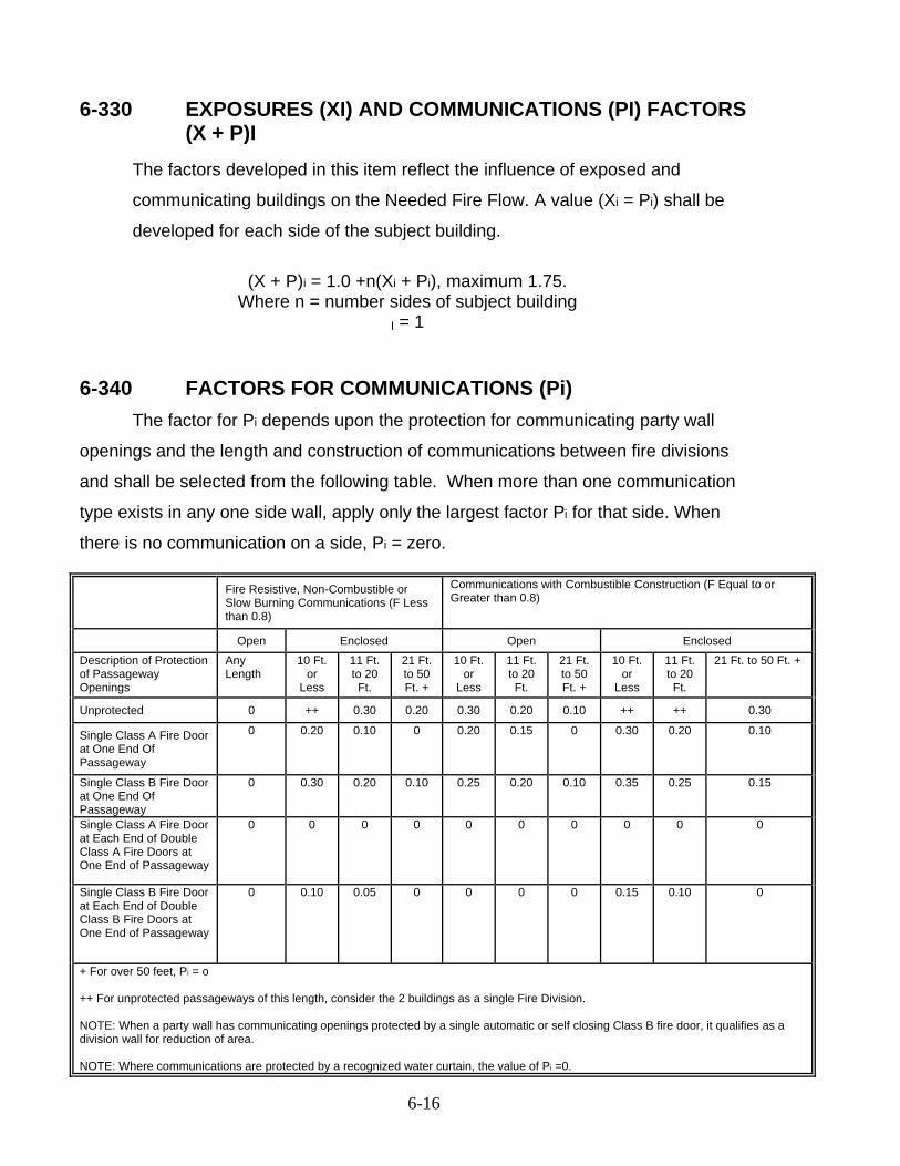
6-330 EXPOSURES (XI) AND COMMUNICATIONS (PI) FACTORS (X + P)I
The factors developed in this item reflect the influence of exposed and
communicating buildings on the Needed Fire Flow. A value (Xi = Pi) shall be
developed for each side of the subject building.
(X + P)i = 1.0 +n(Xi + Pi), maximum 1.75. Where n = number sides of subject building
I = 1
6-340 FACTORS FOR COMMUNICATIONS (Pi)
The factor for Pi depends upon the protection for communicating party wall
openings and the length and construction of communications between fire divisions
and shall be selected from the following table. When more than one communication
type exists in any one side wall, apply only the largest factor Pi for that side. When
there is no communication on a side, Pi = zero. Fire Resistive, Non-Combustible or
Slow Burning Communications (F Less than 0.8)
Communications with Combustible Construction (F Equal to or Greater than 0.8)
Open Enclosed Open Enclosed Description of Protection of Passageway Openings
Any Length
10 Ft. or
Less
11 Ft. to 20 Ft.
21 Ft. to 50 Ft. +
10 Ft. or
Less
11 Ft. to 20 Ft.
21 Ft. to 50 Ft. +
10 Ft. or
Less
11 Ft. to 20 Ft.
21 Ft. to 50 Ft. +
Unprotected 0 ++ 0.30 0.20 0.30 0.20 0.10 ++ ++ 0.30
Single Class A Fire Door at One End Of Passageway
0 0.20 0.10 0 0.20 0.15 0 0.30 0.20 0.10
Single Class B Fire Door at One End Of Passageway
0 0.30 0.20 0.10 0.25 0.20 0.10 0.35 0.25 0.15
Single Class A Fire Door at Each End of Double Class A Fire Doors at One End of Passageway
0 0 0 0 0 0 0 0 0 0
Single Class B Fire Door at Each End of Double Class B Fire Doors at One End of Passageway
0 0.10 0.05 0 0 0 0 0.15 0.10 0
+ For over 50 feet, Pi = o ++ For unprotected passageways of this length, consider the 2 buildings as a single Fire Division. NOTE: When a party wall has communicating openings protected by a single automatic or self closing Class B fire door, it qualifies as a division wall for reduction of area. NOTE: Where communications are protected by a recognized water curtain, the value of Pi =0.

6-17
6-350 EXPOSURE FACTOR (XI)
The factor for Xi depends upon the construction and length to height value
(length of wall in feet, times height in stories) of the exposed building and the distance
between facing walls of the subject building and the exposed building, and shall be
selected from the following table.
FACTOR FOR COMMUNICATIONS (Pi)
Construction of Facing Wall of Exposed Building Construction Coefficient F
Less than 1.5
Construction of Facing Wall of Subject Building
Distance Feet to the Exposed Building
Length Height of Facing Wall of Exposed Building
1.5 Unprotected Openings
Semi-Protected Openings (Wired Glass or Outside open sprinklers)
Blank Wall
Frame, Metal or Masonry with Openings
0 - 10 11 - 30 31 - 60 61 -
100
1 – 100 101 - 200 201 - 300 301 - 400 Over 400 1 - 100 101 - 200 201 - 300 301 - 400 Over 400 1 - 100 101 - 200 201 - 300 301 - 400 Over 400 1 - 100 101 - 200 201 - 300 301 - 400 Over 400
0.22 0.23 0.24 0.25 0.25 0.17 0.18 0.19 0.20 0.20 0.12 0.13 0.14 0.15 0.15 0.08 0.08 0.09 0.10 0.10
0.21 0.22 0.23 0.24 0.25 0.15 0.16 0.18 0.19 0.19 0.10 0.11 0.13 0.14 0.15 0.06 0.07 0.08 0.09 0.10
0.16 0.17 0.18 0.19 0.20 0.11 0.12 0.14 0.15 0.15 0.07 0.08 0.10 0.11 0.12 0.04 0.05 0.06 0.07 0.08
0 0 0 0 0 0 0 0 0 0 0 0 0 0 0 0 0 0 0 0
Blank Masonry Wall Facing Wall of the Expose Building: Use the above table EXCEPT use only the Length-Height of Facing Wall of the Exposed Building ABOVE the height of the Facing Wall of the Subject Building. Buildings five stories or over in height, consider as five stories. When the Height of the Facing Wall of the exposed Building is the Same of Lower than the Height of the Facing Wall of the Subject Building, Xi=0.
6-360 CALCULATION OF NEEDED FIRE FLOW (NFFi) NFFi = (Ci) (Oi) (X + P)i
• When a wood shingle roof covering on the building being considered, or on
exposed buildings can contribute to spreading fires, add 500 gpm to the
6-18
Needed Fire Flow.
• The Needed Fire Flow shall not exceed 12,000 gpm nor be less than 750
gpm.
• The Needed Fire Flow shall be rounded off to the nearest 250 gpm if less
than 2500 gpm and to the nearest 500 gpm if greater than 2500.
SECTION 6-400 SPRINKLER AND STANDPIPE SYSTEMS
Fire department connections shall be located and visible from the street.
Alternate locations must be approved by the Fire Marshal's Office. Connections shall
be located for immediate access by the fire department. Fences, trees, and any similar
obstructions shall not be permitted. Mechanical protection shall be provided for the fire
department connection and the post indicator valve by a nine (9) foot wide raised island
or other approved method. Fire department connections shall be arranged in such a
manner that the use of any one water sprinkler connection will serve all the sprinklers,
and the use of any one standpipe connection will serve all the standpipes within the
building. Fire department connections shall not be less than eighteen (l8) inches and
not more than forty two (42) inches in elevation measured from ground level to the
centerline of the inlets. A fire hydrant shall be provided within one hundred (100) feet of
the fire department connection and away from the building at a distance that is greater
than the height of the adjacent wall. A dedicated easement will be provided for the fire
hydrant and the water line that supplies it. An easement will not be dedicated for the
water main that only supplies the building sprinkler system. In buildings classified as
high rise by the ICC Building Code, the fire department connections shall be located a
minimum of fifty (50) feet from the building. The location shall be approved by the Fire
Marshal's Office. All sprinkler systems shall have externally mounted post indicator
valves and will be located on a masonry building wall or sleeved free standing post
indicator valve. (Refer to Standard Detail FS-3.0 of this article.) The post indicator valve
shall be monitored when required by the use group of the building and locked by an
approved rapid entry lock.

6-19
6-410 Private Fire Service Mains
Fire service main will be a separate connection to the public water main
from domestic service lines unless otherwise directed by the Fire Marshal's
Office. All fire service mains will be privately owned and maintained. A street
valve will be installed on the fire service main at its connection to the public water
main connection by means of a mechanical T. or approved wet tap.
Acceptance testing will be required on all fire service main prior to
concealment and use. All fire service mains will be hydrostatically tested at not
less than two hundred (200) psi for two (2) hours or at fifty (50) psi in excess
of maximum static pressure when the maximum static pressure is in excess of
one hundred and fifty (150) psi.
Concealment of an underground fire service main prior to acceptance
testing may occur with the following conditions:
A. That a visual inspection of the system, by the Fire Marshal or the Site
Inspector, is conducted to verify that piping and anchorage is installed in
an approved manner.
B. That the developer/contractor will assume the risk to make corrections in
the event that the system fails the postponed hydrostatic test.
6-410.1 INSTALLATION AND TESTING OF UNDERGROUND
FIRELINES 1. All installation and testing shall be conducted per NFPA 24, 1995 edition.
2. Fire service main shall have at least 4 feet of cover from the top of the
pipe.
3. All bends and tees shall have thrust blocks.
4. All piping through footers shall have rods to a point at least 5 feet outside
of the building wall.
5. All rods shall be at least 5/8 inch. The number of rods will depend on the
size of the pipe.
6-20
6. All rods, nuts, bolts, washers, clamps, and other restraining devices shall
be coated with a bituminous or other acceptable corrosion-resistive
material.
7. Thrust blocks shall be placed against undisturbed soil or rods shall be
installed with thrust blocks.
8. Rods secured on smooth pipe shall be anchored with 2 clamps, with one
rod in each clamp. Listed retainer-type fittings must be installed per
manufacturer’s instructions.
9. A visual inspection is required before pipe is covered.
10. The contractor is responsible for locating and correcting any leakage. If
pipe is covered before the hydrostatic test, no drop in pressure during the
test is allowed.
11. Fire service main shall not be run under buildings.
12. A hydrostatic test at 200 PSI or 50 PSI over static pressure, whichever is
greater, shall be conducted for 2 hours in the presence of the Fire Marshal
staff.
13. All fire service mains shall be flushed in accordance with Table 6-3.
14. Approved site plans showing size and location of fire service main shall be
on the job site before the inspection or test occurs.
15. All test and permit fees shall be paid before the inspection or test is
performed.
16. Electrical ground wires shall not be connected to the underground fire
service main.
17. Backfill shall be well tamped, free of rock and free of corrosives.
Fire service main flushing will occur prior to any admittance of water
through such a line into any fire sprinkler system. The minimum water flow
required for line flushing will comply with Table 6-3 or the hydraulically
calculated water demand rate of the system, whichever is greater.

6-21
TABLE 6-3
Pipe Size Flush Orifice Size Flow Rate 2 inch 2 inch 60 gpm4 inch 4 inch 400 gpm6 inch 6 inch 750 gpm8 inch 6 inch 1,000 gpm10 inch 6 inch 1,500 gpm12 inch 6 inch 2,000 gpm
6-410.2 POST INDICATOR VALVE
A free-standing post indicator valve shall have vehicle impact protection.
Guard posts shall comply with all of the following requirements:
1. Constructed of steel not less than 4 inches (102mm) in diameter and concrete
filled.
2. Spaced not more than 4 feet (1219mm) between posts on center.
3. Set not less than 3 feet (914mm) deep in concrete footing of not less than a
15 inch (381mm) diameter.
4. Set with the top of the posts not less than 3 feet (914mm) above ground.
5. Located not less than 3 feet (914mm) from the protected object.
6-420 BACKFLOW PREVENTION
The potable water supply to all fire sprinkler systems and standpipes shall
be protected by an approved Double Check Valve (DCV) assembly backflow
prevention device, as a minimum. A higher degree of backflow protection, i.e., a
Reduced Pressure Zone (RPZ) assembly or an Air Gap (AG), may be required
where chemicals can be added to the system or where the system is connected
to a nonpotable secondary water supply. These backflow preventers should be
within the building (New construction) or located in an approved insulated and
heated above grade backflow enclosure if installed on the exterior of a building.
Existing below grade facilities containing backflow preventors that had prior
approval shall be acceptable as long as those vaults (facilities) have been
adequately sized in accordance with Standard Detail FS-3.0 of this article, and
maintained free of water or other contaminants. All valves, fittings, and

6-22
appurtenances shall be listed by Underwriters Laboratory (U.L.) or Factory
Mutual (FM).
Backflow prevention devices shall be tested and maintained in accordance with Section 9.6 of NFPA Standard No. 25, and Article 13 of this manual. SECTION 6-500 EMERGENCY ACCESS
This section specifies the minimum emergency access requirements necessary
to facilitate deployment of fire and rescue apparatus during times of emergency.
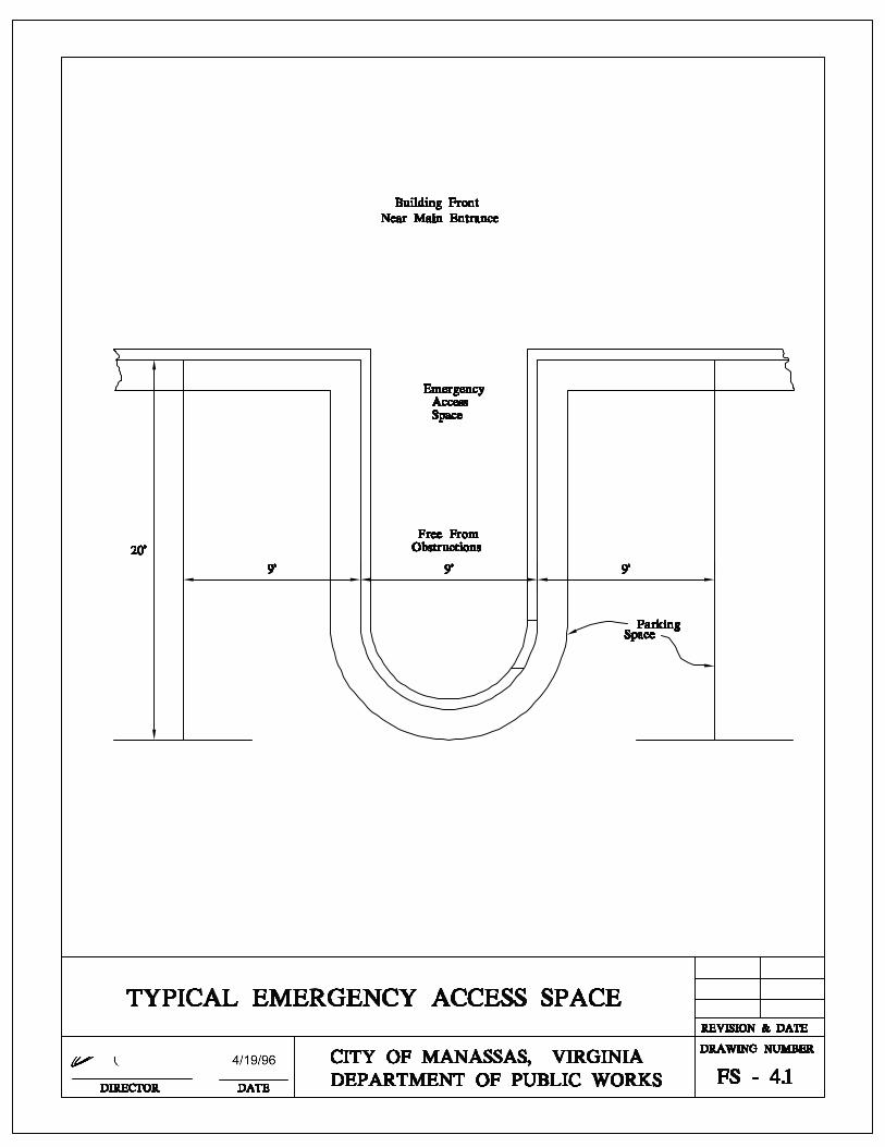
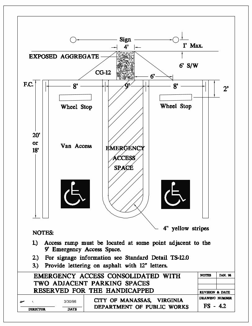
6-510 PARKING LOT SPACE
An unobstructed emergency access space at least 9 feet in width shall be
provided in front of the main entrance(s) of buildings with adjacent vehicle
parking not separated by means of a fire lane. Where parking spaces are
permitted adjacent to commercial strip shopping centers without separation by
means of fire lanes, unobstructed emergency access spaces shall be provided at
100 feet intervals. See Standard Detail FS - 4.1 and FS - 4.2
Exceptions: A. Detached single family dwelling units.
B. Townhome subdivision.
6-520 ACCESS TO REAR OF BUILDINGS Rear access requirements shall comply with the appropriate
development standard outlined in the Zoning Ordinance of the City of
Manassas.
Each lot shall have an unobstructed access to a rear service area
capable of handling emergency equipment if the lot is not otherwise
accessible via a street, driveway, or parking area. This access shall be
constructed of an all weather surface capable of supporting heavy
apparatus.
The minimum access widths permitted in any business or industrial district
shall be twenty-two (22) feet. If such access is also required to serve as a fire
lane then the minimum width shall be twenty-five (26) feet.

6-23
6-530 ACCESS LIMITS The emergency access limit is the maximum distance a building may be
set back from the closest point of emergency vehicle access. These maximum
set back limits shall be measured from the main building entrance to the edge of
pavement, curb line or emergency access. The building height measured in feet
is the distance between the lowest level of fire department access to the floor
level of the top most habitable floor.
In townhouse developments, the maximum distance from the curb line to the
building entrance may not exceed 75 feet.
In apartment and condominium developments the maximum distance from the
curb line to the building entrance shall be 50 feet.
In buildings over three stories in height the maximum setback from the curb or
street or emergency access shall conform to the following guidelines:
Building Height Maximum Set Back 30' - 45' 50' 46' - 60' 40' 61' - 75' 30'
> 75' 20'
6-540 FIRE LANES When necessary, the City Fire Marshal shall designate fire lanes on private
streets and on private property used for commercial, industrial, educational, or
multi-family and townhouse residential purposes. The purpose of the fire lanes
shall be to prevent parking and standing in front of or adjacent to fire hydrants
and to provide clear access to buildings and fire protection equipment.
Fire lanes shall conform to the following specifications:
A. Fire lanes in commercial, residential, industrial, and educational areas shall
be a minimum of 26 feet wide. This 26 feet shall be measured perpendicularly
from the painted curb or the edge of the pavement.
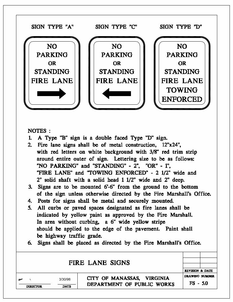
B. Approved fire lane signs must meet the following specifications:
1. Metal construction, approximately 12 inches by 18 inches.
6-24
2. Red letters on white background with 3/8 inch red trim strip around the
entire outer edge of the sign.
3. Lettering on sign to be: "NO PARKING OR STANDING FIRE LANE.”
Arrows must be on signs to point to and indicate the area designated as a
fire lane. As described by Standard Detail FS - 5.0 of this Article.
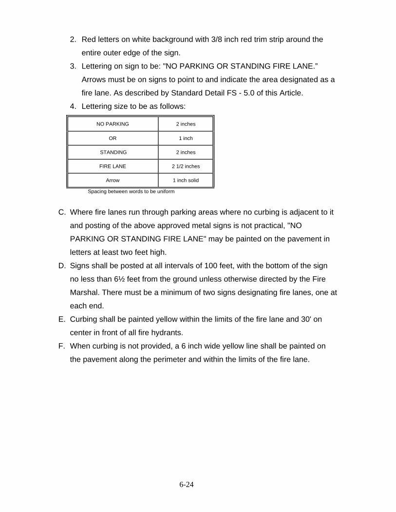
4. Lettering size to be as follows:
NO PARKING 2 inches
OR 1 inch
STANDING 2 inches
FIRE LANE 2 1/2 inches
Arrow 1 inch solid
Spacing between words to be uniform
C. Where fire lanes run through parking areas where no curbing is adjacent to it
and posting of the above approved metal signs is not practical, "NO
PARKING OR STANDING FIRE LANE" may be painted on the pavement in
letters at least two feet high.
D. Signs shall be posted at all intervals of 100 feet, with the bottom of the sign
no less than 6½ feet from the ground unless otherwise directed by the Fire
Marshal. There must be a minimum of two signs designating fire lanes, one at
each end.
E. Curbing shall be painted yellow within the limits of the fire lane and 30' on
center in front of all fire hydrants.
F. When curbing is not provided, a 6 inch wide yellow line shall be painted on
the pavement along the perimeter and within the limits of the fire lane.

6-25
Fire Lane Parking:
Street width curb to curb One-way Traffic Two-way traffic 26 feet width No parallel parking on
either side of street No parallel parking on either side of street
27 feet to 29 feet Parallel parking on one side of street to be determined by the Fire Marshal
No parallel parking on either side of the street
30 feet to 34 feet Parallel parking allowed on both sides of street
Parallel parking on one side to be determined by the Fire Marshal
35 feet or greater Parallel parking allowed on both sides of the street
Parallel parking allowed on both sides of the street
Fire Lanes require Fire Marshal inspection and approval before final occupancy.

6-26
SECTION 6-600 FIRE SERVICE SYSTEM DETAILS
TABLE OF CONTENTS DRAWING NO.
FIRE HYDRANT COLOR CODE .................................................................F.S-1.0
FIRE HYDRANT SETTING...........................................................................F.S-1.1
TYPICAL FIRE HYDRANT LOCATION........................................................F.S-1.2
FIRE HYDRANT MECHANICAL PROTECTION ..........................................F.S-1.3
RESTRAINED JOINT ...................................................................................F.S-2.0
DETECTOR CHECK VALVE VAULT ...........................................................F.S-3.0
TYPICAL FIRE HYDRANT ISLAND .............................................................F.S-4.0
TYPICAL EMERGENCY ACCESS SPACE..................................................F.S-4.1
EMERGENCY ACCESS SPACE CONSOLIDATION ...................................F.S-4.2
FIRE LANE SIGNS.......................................................................................F.S-5.0
FIRE HYDRANT OUT-OF-SERVICE SIGN..................................................F.S-5.1
POST INDICATOR VALVES-WALL MOUNTED ..........................................F.S-6.0
POST INDICATOR VALVES ........................................................................F.S-6.1


4/19/96


6 - 42
(This page has been intentionally left blank)