armstrong #4 grinder maintenance / rebuilding
TRANSCRIPT

Armstrong #4 Grinder Maintenance
/ Rebuilding

First, some History
Manufacturing Company
Established in 1902, Portland Oregon USA

E.P. Armstrong: The Man Behind
the Machinery
Born in 1865, (the year
the civil war ended in
the U.S.), in the village
of Haydon Bridge
England, Edward
would wait until 4
years of age to move to
Connecticut and help
his father in his wagon
spoke factory.

Necessity is the Father of Invention
While Edward and his brother were quite young
they installed a set of spoke machinery. The
machine consisted of a 30-inch bolting saw with
36 teeth fed by hand. The hard work led
Edward to experimenting with number of teeth
and feed speeds. Working out these
fundamental savings was the beginning of
Edwards life work.

In the beginning, he filed
E.P. gained some of his early experience as a filer at the Ed Brooks Mill at Stafford Springs, Connecticut.

Armstrong Heads West
Portland,
Oregon
Connecticut
At 22, after helping rebuild the Ed Brooks mill due to a fire,
Armstrong traveled through 14 states over the course of 17
years where he observed every size and type of saw used.

Standard Box and Lumber Filing Room
E.P. Armstrong (at left) in the file room at Standard Box and Lumber Company in Portland, Oregon. Note the flat belt running overhead that powered the machinery in the file room.
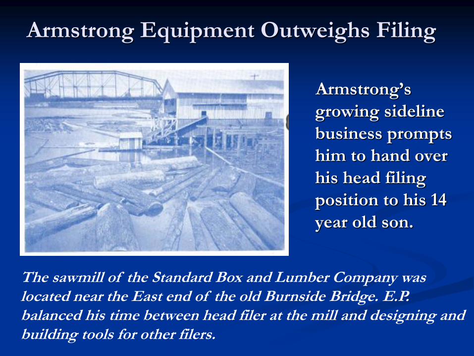
Armstrong Equipment Outweighs Filing
Armstrong’s
growing sideline
business prompts
him to hand over
his head filing
position to his 14
year old son.
The sawmill of the Standard Box and Lumber Company was located near the East end of the old Burnside Bridge. E.P. balanced his time between head filer at the mill and designing and building tools for other filers.

E.P. opens a small jobbing machine
shop and names it Armstrong Mfg. Co.
The first factory of
the Armstrong
Manufacturing
Company general
machine works was
located in downtown
Portland.

E.P.’s son Harry joins Armstrong
Left: E.P. busily at work at his drafting table, designing tools and parts. Right: Son Lloyd spent most of his time managing the day-to-day business of the company.
Harry left the Standard Box
& Lumber Company, when
the mill burned in 1915, to
join his father in the
business. They delivered
swages, shapers and spare
parts to filers locally on foot,
walking to the 30 sawmills
that lined the Willamette
river just within the city
limits of Portland.

One of the First #4s was Built in 1924
#4 Armstrong grinder
from the 1950’s
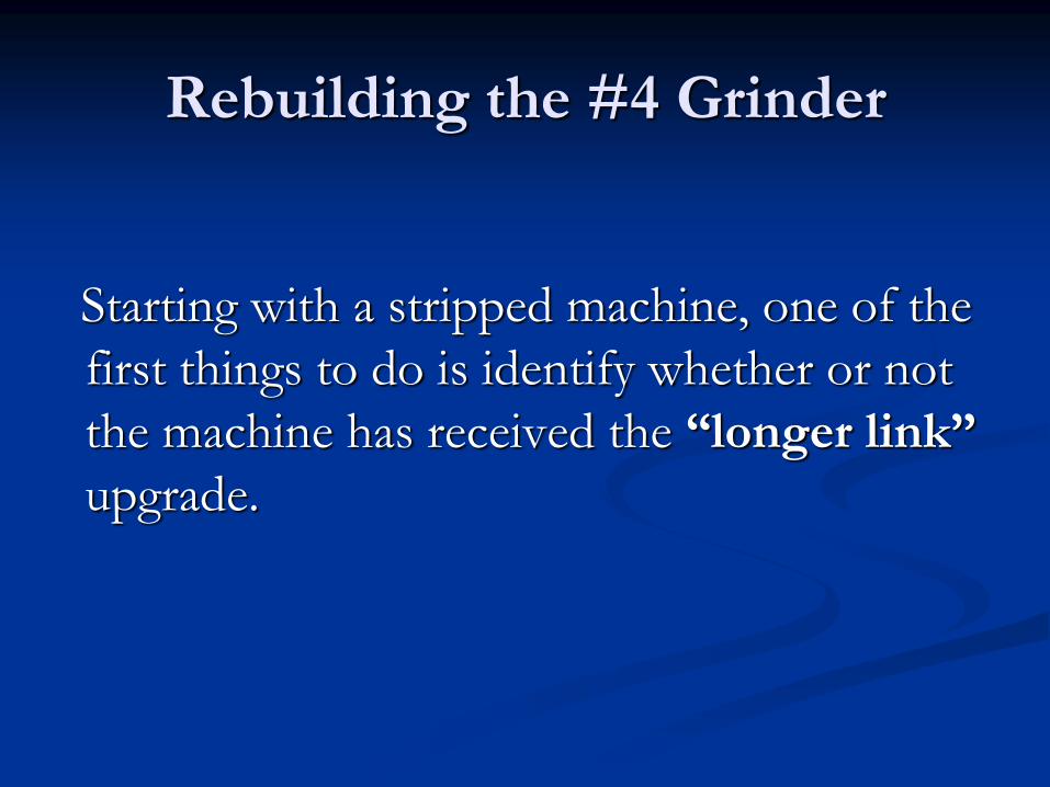
Rebuilding the #4 Grinder
Starting with a stripped machine, one of the
first things to do is identify whether or not
the machine has received the “longer link”
upgrade.

Longer carriage links help alleviate “old wheel
new wheel” syndrome. (loosing the hook line)
Oval cutout,
Not a Cast Part

Saving your Hook Line
NEW LONGER LINKS
Since 1980, NEW LONGER LINKS (Part No.
461), for the Nos. 4 and 4-21/22 sharpeners
have allowed additional wear on the grinding
wheel while maintaining the hook and tooth
shape. The 3/4" longer links are completely
interchangeable with old-style, Part No.341.
Overall height of the new links is 8 3/16”
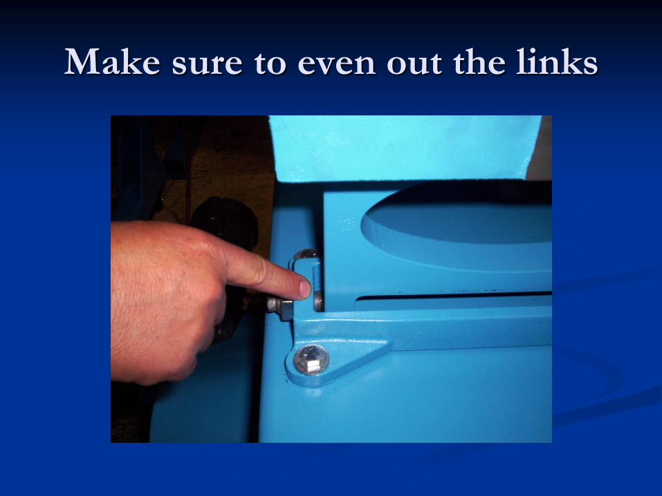
Make sure to even out the links

Always replace bushings when
replacing cone screws
Install new Cone screws and Bushings. Don’t forget to
add a small amount of grease to the bushings.
Bushings
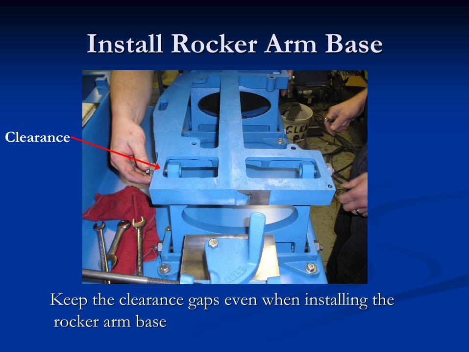
Install Rocker Arm Base
Keep the clearance gaps even when installing the
rocker arm base
Clearance
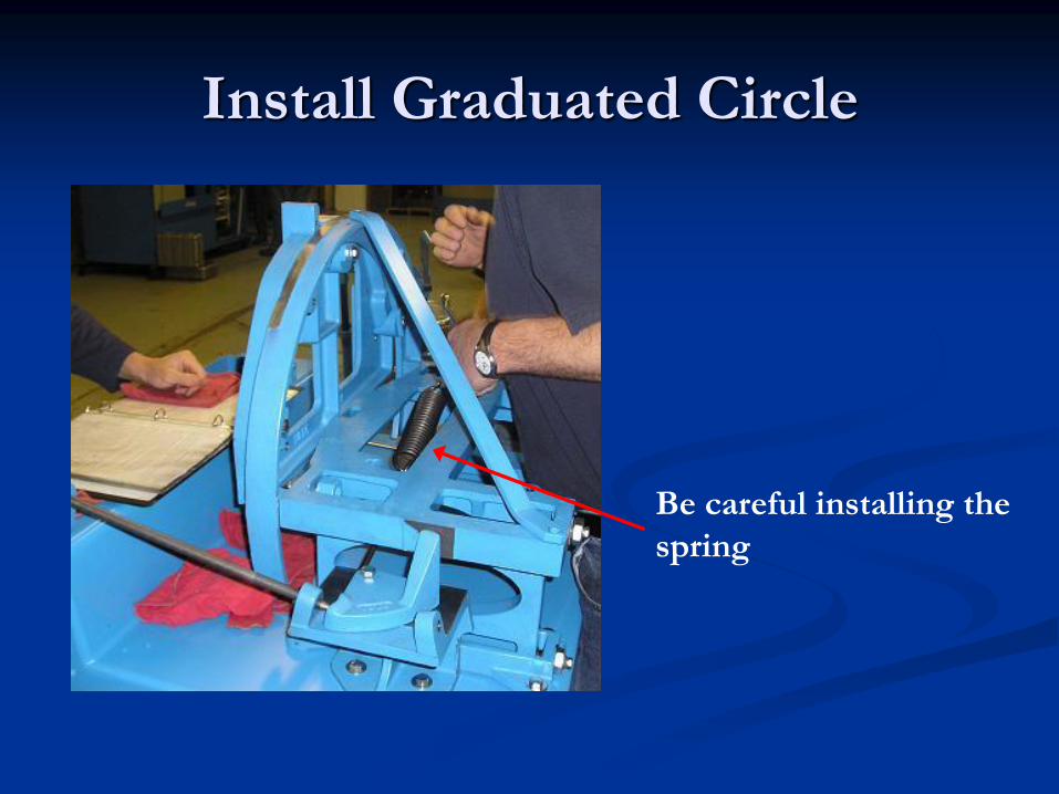
Install Graduated Circle
Be careful installing the
spring

Face Infeed Spring
Tension Spring until 1.5”
is protruding beyond
the locking nut.
Face infeed threaded shaft
1.5 inches here
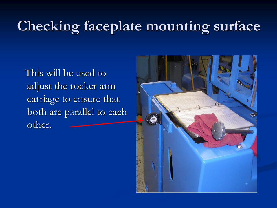
Checking faceplate mounting surface
This will be used to
adjust the rocker arm
carriage to ensure that
both are parallel to each
other.
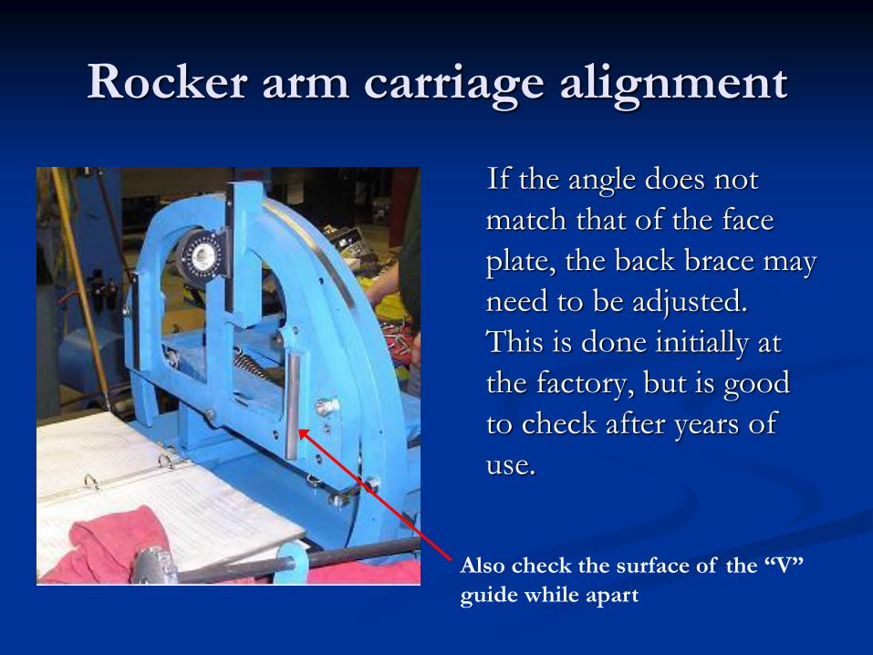
Rocker arm carriage alignment
If the angle does not
match that of the face
plate, the back brace may
need to be adjusted.
This is done initially at
the factory, but is good
to check after years of
use.
Also check the surface of the “V”
guide while apart
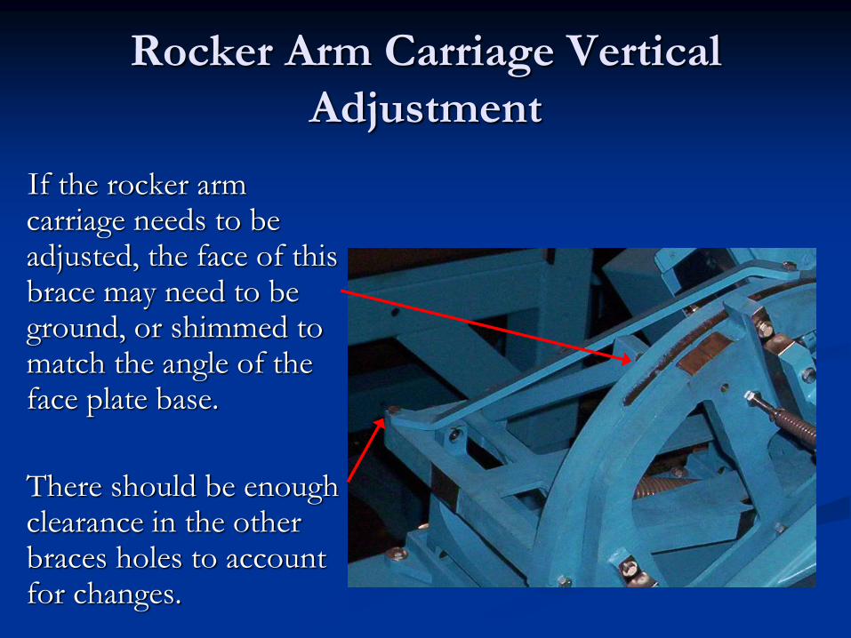
Rocker Arm Carriage Vertical
Adjustment
If the rocker arm carriage needs to be adjusted, the face of this brace may need to be ground, or shimmed to match the angle of the face plate base.
There should be enough clearance in the other braces holes to account for changes.

Running true in the Vee Guide
If there is
uneven
motion on the
Vee, then the
hanging
straps will
need to be
adjusted.
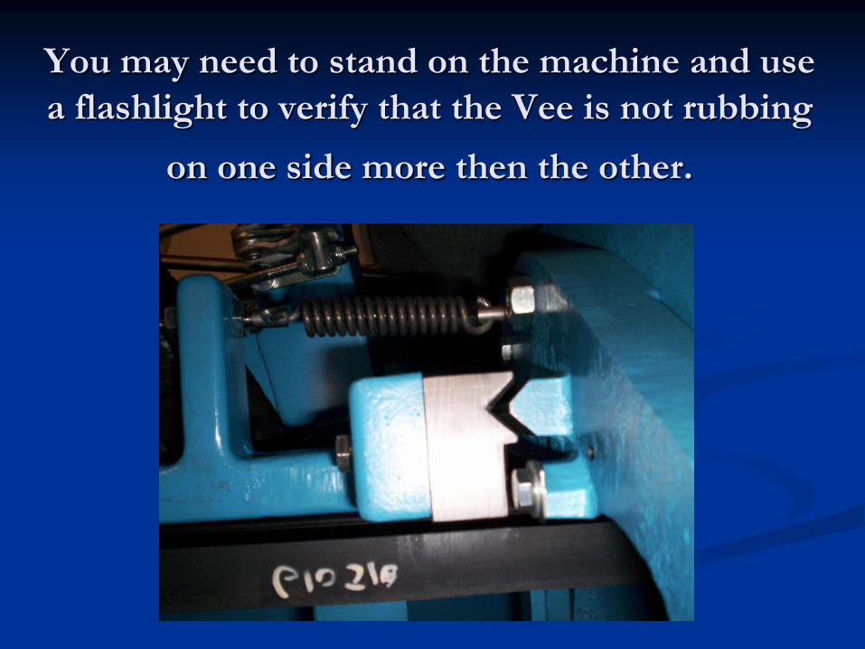
You may need to stand on the machine and use
a flashlight to verify that the Vee is not rubbing
on one side more then the other.
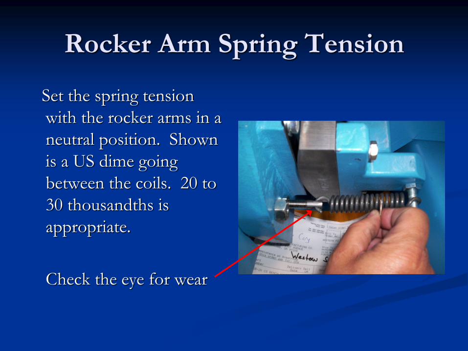
Rocker Arm Spring Tension
Set the spring tension
with the rocker arms in a
neutral position. Shown
is a US dime going
between the coils. 20 to
30 thousandths is
appropriate.
Check the eye for wear

Replace Rocker Arm Cone Screws
Replace cone screws and
bushings on rocker arms.
Again, remember to even
up all clearance gaps.
If they are over tightened
the rocker arms may pull
away from the hanging
straps

Adjustment of Faceplate
Although apparently simple
looking, the faceplate requires
a minimum of 3 adjustments
to assure a saw runs correctly.
This first one is verifying that
it is slightly proud of the saw
carriage. Make sure the
straight edge is firmly against
the top and bottom carbide
insert.
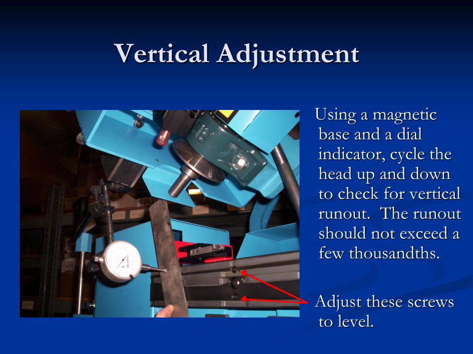
Vertical Adjustment
Using a magnetic base and a dial indicator, cycle the head up and down to check for vertical runout. The runout should not exceed a few thousandths.
Adjust these screws to level.

Linear Runout
Attach a dial indicator to
the feed arm to check for
runout on the saw entry
side of the faceplate.
Use the adjustment
screws so that the dial is
reading ~0.001 growth
by the end of the stroke
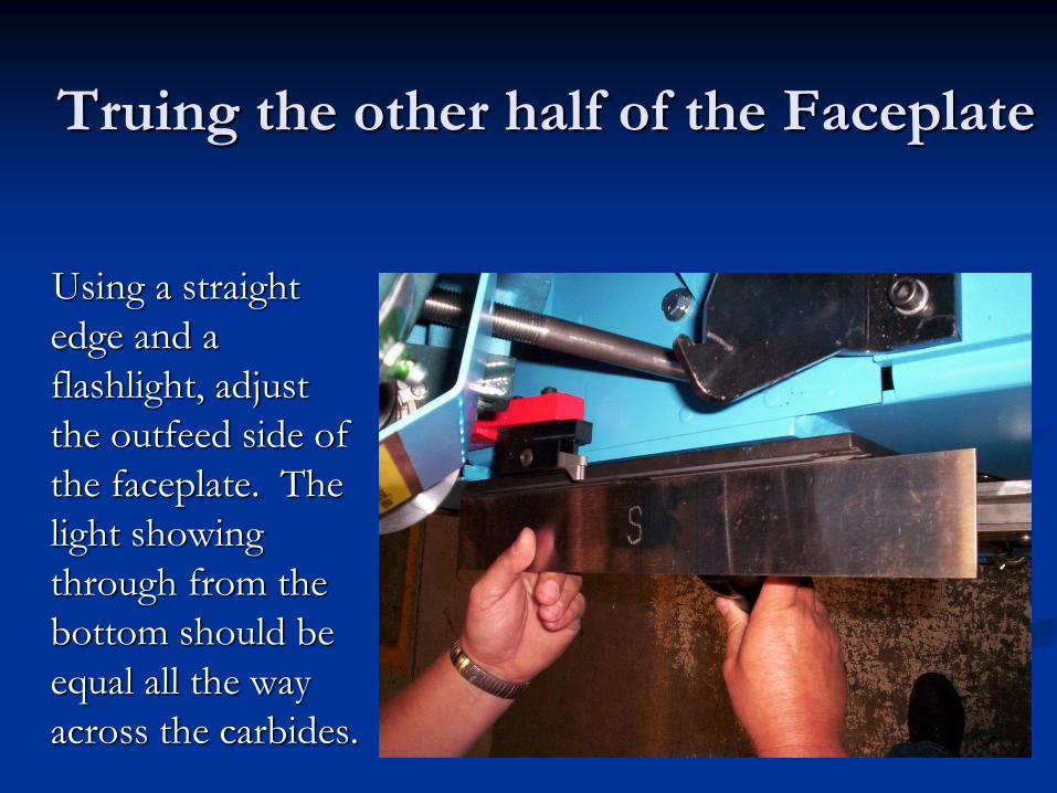
Truing the other half of the Faceplate
Using a straight
edge and a
flashlight, adjust
the outfeed side of
the faceplate. The
light showing
through from the
bottom should be
equal all the way
across the carbides.

Faceplate and Stand Height
The faceplate should now be set up to push the saw
out 0.002” inches over its full length. This ensures
that the feed finger helps hold the saw against the
faceplate. The saw should also be running uphill ever
so slightly. 1/16” between the first post bracket and
the saw carriage is sufficient. This ensures that the
saw does not lift up off of the carriage while feeding.
(Feed finger will slide down the face a fraction to help hold down
the saw.)
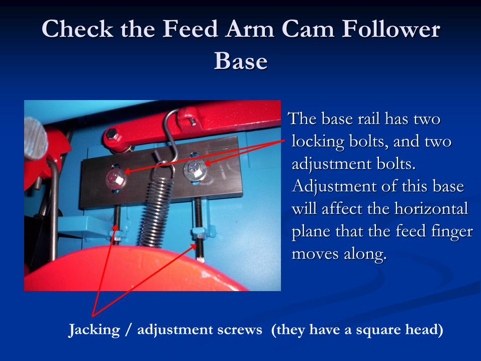
Check the Feed Arm Cam Follower
Base
The base rail has two
locking bolts, and two
adjustment bolts.
Adjustment of this base
will affect the horizontal
plane that the feed finger
moves along.
Jacking / adjustment screws (they have a square head)

Arbor Alignment
Removing two of the
four bolts that hold the
face plate, mount the
Armstrong Arbor
Alignment gauge.
Gauge

Zero out the Dial Indicator

Check both sides of the Arbor and adjust
to the gauge saw you are running

Adjust the base, not the Cone Screws
Make Adjustments Here
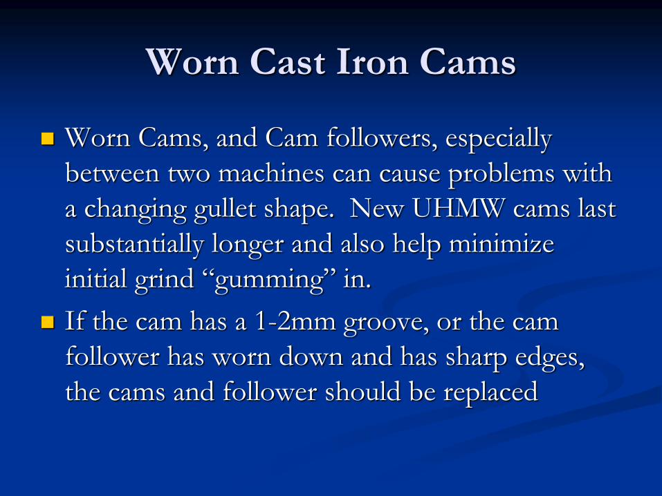
Worn Cast Iron Cams
Worn Cams, and Cam followers, especially
between two machines can cause problems with
a changing gullet shape. New UHMW cams last
substantially longer and also help minimize
initial grind “gumming” in.
If the cam has a 1-2mm groove, or the cam
follower has worn down and has sharp edges,
the cams and follower should be replaced

Cam Timing
Older Cast Iron Cams have a raised 1 inch “bar” in the casting that usually comes painted White.
Use a tape measure and the floor for initial timing
UHMW Cams have timing hole
Run a small round bar through both cams, and adjust initially by making the bar parallel to the cam shaft.
Fine tuning requires stepping the machine through a cycle by hand.