armorconnect power and control media selection...
TRANSCRIPT

Selection Guide
ArmorConnect Power and Control MediaBulletins 280, 888, 889, 898

2 Publication 280PWR-SG001A-EN-P

Bulletin 280, 888, 889, 898
Power Media
3Visit our website: www.ab.com/catalogs
Publication 280PWR-SG001A-EN-P
Product Overview
Three-Phase Power Media
Three-Phase Power Trunk Cable
Three-Phase Power Drop Cable
Three-Phase Power Tees and Reducers
Three-Phase Power Receptacles
Three-Phase Power Accessories
Description
� Cordset - Cable withintegral female or maleconnector on one end
� PatchCord - Cable withintegral female or maleconnector on each end
� Cordset - Cable withintegral female or maleconnector on one end
� PatchCord - Cable withintegral female or maleconnector on each end
� Tee - Connects to asingle drop line to trunkwith M35 connectors
� Reducing Tee -Connects to a singleM22 drop line to trunkM35 connector
� Reducer - Connectsfrom M35 maleconnector to M22female connector
� Female receptacles area panel mountconnector with flyingleads
� Male receptacles are amotor juction boxmounted connector withflying leads
� Field-installablereceptacle for customlength cable
� Sealing Caps offered inversions to interfacewith female or maleconnectors
� Locking Clips clamshelldesign clips over threepower phase connectorto limit customer access
Features
� Rated for Motor BranchCircuits
- Meets UL 2237 forIndustrial Machinery
- 65 kA High faultrating (SCCR)
- Rated for washdown environments
� Straight or right angleconnectors
� 4-pin connector type� Cable rating:
TC-ER/STOOW� Multiple standard
lengths
� Rated for Motor BranchCircuits
- Meets UL 2237 forIndustrial Machinery
- 65 kA High faultrating (SCCR)
- Rated for washdown environments
� Straight or right angleconnectors
� 4-pin connector type� Cable rating: TC-
ER/STOOW� Multiple standard
lengths
� Rated for Motor BranchCircuits
- Meets UL 2237 forIndustrial Machinery
- 65 kA High faultrating (SCCR)
- Rated for washdown environments
� Trunk Tee, Reducing Teeand Reducer
� 4-pin connector type
� Rated for Motor BranchCircuits
- Meets UL 2237 forIndustrial Machinery
- 65 kA High faultrating (SCCR)
- Rated for washdown environments
� Male and femaleconfigurations
� 4-pin connector type� 1/2 in. NPT� Available in 1 meter
length
� Sealing Caps - Availablein M35 and M22 styles
� Locking Clips -Designed for M35 andM22 connectors
Rated Voltage 600V 600V 600V 600V ⎯
Connector BodyDimensions
� Straight:88.9 mm x 38.6 mm
� Right Angle:75.5 mm x 74 mm
� Straight:56. mm x 25.4 mm
� Right Angle:44.9 mm x 40.4 mm
� Trunk Tee:108 mm x 73.6 mm
� Reducing Tee:108 mm x 65.5 mm
� Reducer:112.5 mm x 38.1 mm
� M22 Female:33.45 mm x 25.45 mm
� M22 Male:28.04 mm x 25.45 mm
� M35 Female:71.12 mm x 38.10 mm
� M35 Male:63.50 mm x 38.10 mm
⎯
Product Selection Page 9 Page 10 Page 11 Page 15 page 21
Control Power Media
Control Power Cordsets & Patchcords
Control Power T-ports
Control Power Receptacles
Control Power Shorting Plugs
Control Power Accessories
Description� Cable with integral
connector on either one orboth ends
� Cable with single maleconnector attached totwo female connectors
� Panel mount connectorwith flying leads
� Integral connector withleads shorted forspecific applicationrequirements
� Sealing caps, mountingnuts, and sealingwashers
Features
� 6-pin/5-used configuration� Male and female� Straight or right angle
versions� 16 AWG conductors, cable
dual rated UL TC/OpenWiring and STOOW
� Multiple standard lengths
� 6-pin/5-usedconfiguration
� Compact design� Color-coded E-stop in
and E-stop outconfigurations
� 6-pin/5-usedconfiguration
� Male and female� 16 AWG conductors� 1/2 NPT mounting
threads� Multiple standard
lengths
� 6-pin/5-usedconfiguration
� Male� Multiple versions color
coded for simpleidentification
� Rugged durableconstruction
� Designed to mate withcontrol power media
Rated Voltage 600V 600V 600V 600V ⎯
Connector BodyDimensions
� Straight:56 x 25 mm (2.2 x 1 in.)
� Right Angle:40 x 45 mm (1.6 x 1.8 in.)
72 x 64 mm (2.8 x 2.5 in.) 30 x 25 mm (1.2 x 1 in.) 56 x 25 mm (2.2 x 1 in.) ⎯
Product Selection Page 17 Page 18 Page 19 Page 20 Page 21

Bulletin 280, 888, 889, 898
Power Media
4Visit our website: www.ab.com/catalogs
Publication 280PWR-SG001A-EN-P
Product Overview
DescriptionThe power media offers both three-phaseand control power cable systems ofcordsets, patchcords, receptacles, tees,reducers and accessories, to be used withthe ArmorStart Distributed Motor Controller.These cable system components allowquick connection of ArmorStart DistributedMotor Controllers, thereby reducinginstallation time. They provide for repeatable,reliable connection of the three-phase andcontrol power to the ArmorStart DistributedMotor Controller and motor, by providing aplug and play environment that also avoidssystem mis-wiring.
Compared to the traditional conduitinstallations, with power media you profitand benefit from:� Reduce commissioning time� Plug and play design eliminates wiring
errors� Increased system design flexibility� No special tools required� Reduced labor costs
Three-Phase Power MediaThe three-phase power media offers quickdisconnect cables that provide a secureconnection to the ArmorStart DistributedMotor Controller. The connectors can bestraight or right angled and are physicallykeyed to prevent wiring mishaps. Thecabling options include:� Cordsets: Cable with integral male or
female connector at one end and flyingleads at the other
� Patchcords: Cable with integralconnector at each end (one male, onefemale)
Control Power MediaThe control power media offers a minidisconnect cable that provides a secureconnection to the ArmorStart DistributedMotor Controller. The control power mediacomponents are a 6-pin/5-used configurationto prevent mis-wiring with networkconnectors. The connectors can be straightor right angled and are physically keyed to prevent wiring mishaps. The cablingoptions include:� Cordsets: Cable with integral male or
female connector at one end and flyingleads at the other
� Patchcords: Cable with integralconnector at each end (one male, onefemale)
The control power tees offers flexibility in system design. The T-port connects asingle drop line to the trunk. Three types of tees are offered. The E-stop In tee is usedto connect to the Bulletin 800F On-MachineE-Stop station using a control power mediapatchcord. The E-stop Out tee is used withcordset or patchcord to connect to theArmorStart Distributed Motor Controller.And the ArmorStart Auxiliary tees allowusers to apply standard 4-wire auxiliarypower down the trunk to other tees anddevices.
The receptacles provide a termination pointat the panel and ArmorStart DistributedMotor Controller. The female receptaclescan be used for a panel mount connection.The male receptacles can be used for aquick disconnect at the ArmorStartDistributed Motor Controller with glandplate design.
Note: Refer to your local electrical code for proper application and protection of long lengthpower cable to minimize physical damage and appropriate short-circuit or ground-faultprotection for the assembly. See application note 290-AP001 for additional information.
The three-phase power tee, reducing tee,and reducer offers flexibility in systemdesign.
The receptacles provide a termination pointat the panel and motor junction box. Thefemale receptacles can be used for a panelmount connection. The male receptaclescan be used for a quick disconnect at themotor junction box.Field-installable receptacles allow forcustom power cable lengths. This reducesthe amount of excess cable and provides aneater appearance to machines. Selectingjust a few cordsets provides the sufficientcable lengths needed to meet the requiredapplications. This minimizes project costsand complexity by reducing the number ofdifferent part numbers that are necessary.Three-phase power media componentsare rated for motor branch circuits perUL 2237.

1. Three-Phase Power Trunk - Patchcord cable with integral female or male connector on each end (Example Cat. No.: 280-PWRM35A-M*)
2. Three-Phase Drop Cable - PatchCord cable with integral female or male connector on each end (Example Cat. No.: 280-PWRM22A-M*)
3. Three-Phase Power Tees and Reducer - Tee connects to a single drop line to trunk with quick change connectors (Cat. No.: 280-T35)Reducing Tee connects to a single drop line (Mini) to trunk (Quick change) connector (Cat. No.: 280-RT35)Reducer connects from quick change male connector to mini female connector(Cat. No.: 280-RA35)
4. Three-Phase Power Receptacles - Female receptacles are a panel mount connector with flying leads (Cat. No.: 280-M35F-M1)
Bulletin 280, 888, 889, 898
Power Media
5Visit our website: www.ab.com/catalogs
Publication 280PWR-SG001A-EN-P
Three-Phase Power Media Diagram
Three-Phase Power Media System Overview
RESET
OFF
Bulletin 280/281 ArmorStart
Bulletin 283 ArmorStart
Bulletin 284 ArmorStart
PLC
Bulletin 1492FBBranch Circuit
Protective Device
Enclosure
Bulletin 1606Power Supply
Bulletin 800F Emergency Stop Pushbutton
1606-XLSDNET4 DeviceNet
Power Supply
Stop

Bulletin 280, 888, 889, 898
Power Media
6Visit our website: www.ab.com/catalogs
Publication 280PWR-SG001A-EN-P
Control Power Media Diagram
Control Power Media System Overview
RESET
OFF
Bulletin 280/281 ArmorStart
Bulletin 283 ArmorStart
Bulletin 284 ArmorStart
PLC
Bulletin 1492FBBranch Circuit
Protective Device
Enclosure
Bulletin 1606Power Supply
Bulletin 800F Emergency Stop Pushbutton
1606-XLSDNET4 DeviceNet
Power Supply
Stop
6. Control Power Media Patchcords - PatchCord cable with integral female or male connector on each end (Example Cat. No.: 889N-F65GFNM-*)
7. Control Power Tees - The E-stop In Tee (Cat. No.: 898N-653ST-NKF) is used to connect to the Bulletin 800F On-Machine E-Stop stationusing a control power media patchcord. The E-stop Out tee (Cat. No.: 898N-653ES-NKF) is used with cordset or patchcord to connectto the ArmorStart Distributed Motor Controller.
8. Control Power Receptacles - Female receptacles are a panel mount connector with flying leads (Cat. No.: 888N-D65AF1-*)
Bulletin 280, 888, 889, 898
Power Media
7Visit our website: www.ab.com/catalogs
Publication 280PWR-SG001A-EN-P
DeviceNet Media Diagram
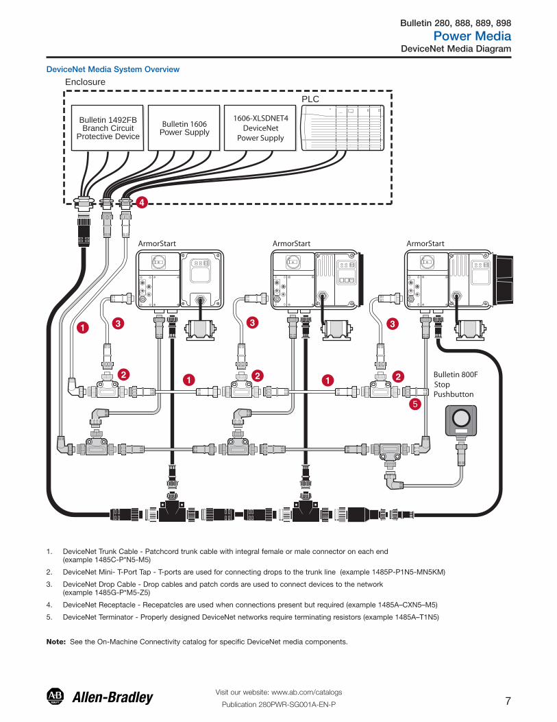
DeviceNet Media System Overview
RESET
OFF
Bulletin 280/281 ArmorStart
Bulletin 283 ArmorStart
Bulletin 284 ArmorStart
PLC
Bulletin 1492FBBranch Circuit
Protective Device
Enclosure
Bulletin 1606Power Supply
Bulletin 800F Emergency Stop Pushbutton
1606-XLSDNET4 DeviceNet
Power Supply
5
Stop
1. DeviceNet Trunk Cable - Patchcord trunk cable with integral female or male connector on each end(example 1485C-P*N5-M5)
2. DeviceNet Mini- T-Port Tap - T-ports are used for connecting drops to the trunk line (example 1485P-P1N5-MN5KM)
3. DeviceNet Drop Cable - Drop cables and patch cords are used to connect devices to the network (example 1485G-P*M5-Z5)
4. DeviceNet Receptacle - Recepatcles are used when connections present but required (example 1485A–CXN5–M5)
5. DeviceNet Terminator - Properly designed DeviceNet networks require terminating resistors (example 1485A–T1N5)
Note: See the On-Machine Connectivity catalog for specific DeviceNet media components.
Bulletin 280, 888, 889, 898
Power Media
8Visit our website: www.ab.com/catalogs
Publication 280PWR-SG001A-EN-P
Ethernet and Control Power Media Diagram
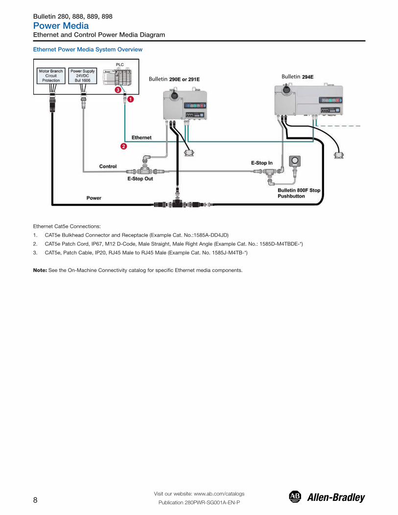
Ethernet Power Media System Overview
Bulletin Bulletin
Ethernet Cat5e Connections:
1. CAT5e Bulkhead Connector and Receptacle (Example Cat. No.:1585A-DD4JD)
2. CAT5e Patch Cord, IP67, M12 D-Code, Male Straight, Male Right Angle (Example Cat. No.: 1585D-M4TBDE-*)
3. CAT5e, Patch Cable, IP20, RJ45 Male to RJ45 Male (Example Cat. No. 1585J-M4TB-*)
Note: See the On-Machine Connectivity catalog for specific Ethernet media components.

Bulletin 280
Three-Phase Power Media
9Visit our website: www.ab.com/catalogs
Publication 280PWR-SG001A-EN-P
Product Selection/Specifications/Approximate Dimensions
Bulletin 280 ⎯ Three-Phase Power Trunk Cables (Cordsetsand Patchcords)
Standards ComplianceUL 2237
CertificationsUL Listed (File No. E318496,Guide PVVA)
Product SelectionCordsets ‡
Patchcords ‡
Specifications
Mechanical
Coupling Nut Black anodized aluminum
Housing Black PVC
Insert Black PVC
Cable Diameter 0.775 in. +/- 0.12 in. (19.68 mm +/- 0.5 mm) withfour 10 AWG conductors
Electrical
Contacts Copper alloy with gold over nickel plating
Cable Black PVC, dual rated UL TC/Open Wiring andSTOOW
Cable Rating 600V AC/DC
Assembly Rating 4-pin — 10 AWG, 600V @ 25 A
Short Circuit CurrentRating (SCCR)
Circuit Breaker: Suitable for use on a circuitcapable of delivering not more than 65 000 RMS
symmetrical amperes at 480V AC maximum whenprotected by Bul. 140U-H frame circuit breaker, not
rated more than 480V, 100 A and a maximuminterrupting of 65 000 RMS symmetrical amperes.
Fusing: Suitable for use on a circuit capable ofdelivering not more than 65 000 RMS symmetricalamperes at 600V AC maximum when protected by
CC, J, and T class fuses.
Environmental
Enclosure Rating IP67, UL Type 4/12 & NEMA 6P; 1200 psi washdown
Operating TemperatureUL Type TC 600V 90 °C Dry 75 °C Wet, ExposedRun (ER) or MTW 600V 90 °C or STOOW 105 °C
600V - CSA STOOW 600V FT2
Pinout and Color CodeFace View Pinout
4-Pin
Female Male
Color Code 1 Black 2 Green/YellowExtended PIN
3 Red4 White
Approximate DimensionsDimensions in millimeters (inches). Dimensions are not intended tobe used for manufacturing purposes and are subject to change.
Pin Count Assembly Rating
Cat. No.
Straight Female Right-Angle Female Straight Male Right-Angle Male
4-pin 10 AWG, 600V, 25 A 280-PWRM35E-M� 280-PWRM35F-M� 280-PWRM35G-M� 280-PWRM35H-M�
Pin Count Assembly Rating
Cat. No.
Straight FemaleStraight Male
Right-Angle FemaleStraight Male
Straight FemaleRight-Angle Male
Right-Angle FemaleRight-Angle Male
4-pin 10 AWG, 600V, 25 A 280-PWRM35A-M� 280-PWRM35B-M� 280-PWRM35C-M� 280-PWRM35D-M�
‡ Stainless steel version may be ordered by adding S to the cat. no. (Example: Cat. No. 280S-PWRM35A-M*)
�Replace symbol with code from table below that represents length desired
Feet 1.62 3.3 4.9 6.5 8.1 9.8 13.1 19.7 26.2 32.8 39.4 45.9 49.2 65.6 82.0 98.4 114.8
Meters 0.5 1 1.5 2 2.5 3 4 6 8 10 12 14 15 20 25 30 35
Code 05 1 015 2 025 3 4 6 8 10 12 14 15 20 25 30 35
88.9 (3.50)
38.6(1.52)
Female straight(1.95 - 2.25)
(2.94)
(1.52)
74.7
49.5 - 57.1
38.6
Female 90 deg.
88.9 (3.50)
38.6(1.52)
Male straight
(1.95 - 2.25)
(2.94)
(1.52)
74.7
49.5 - 57.1
38.6
Male 90 deg.
Example of Patchcord Example of Cordset
Table of Contents
Accessories.................. 21� Listed per UL 2237 for use in motor branch circuits per NFPA 79� One piece molded design, M35 connection� Can be used as a drop cable for ArmorStart Distributed Motor
Controller or when desired to minimize voltage drops on extendedcable runs

Bulletin 280
Three-Phase Power Media
10Visit our website: www.ab.com/catalogs
Publication 280PWR-SG001A-EN-P
Product Selection/Specifications/Approximate Dimensions
Standards ComplianceUL 2237
CertificationsUL Listed (File No. E318496,Guide PVVA)
Cordsets ‡
Patchcords ‡
Specifications
Mechanical
Coupling Nut Black anodized aluminum
Housing Black PVC
Insert Black PVC
Cable Diameter
0.43 in. +/- 0.12 in. (10.9 mm +/- 0.5 mm) with four16 AWG conductors
0.58 in. +/- 0.12 in. (14.7 mm +/- 0.5 mm) with four14 AWG conductors
Electrical
Contacts Brass with gold over nickel plating
Cable Black PVC, dual rated UL TC/Open Wiring andSTOOW
Cable Rating 600V AC/DC
Assembly Rating 4-pin — 16 AWG, 600V @ 10 A4-pin — 14 AWG, 600V @ 15 A
Short Circuit CurrentRating (SCCR)
Fusing: Suitable for use on a circuit capable ofdelivering not more than 65 000 RMS symmetricalamperes at 600V AC maximum when protected by
CC, J, and T class fuses, rated 40 A non-timedelay or 20 A time delay.
Circuit Breaker: Suitable for use on a circuitcapable of delivering not more than 45 000 RMSsymmetrical amperes at 480Y/277V AC maximum
when protected by Cat. No. 140U-D6D3-C30circuit breaker, not rated more than 480Y/277V,30 A, having an interrupting rating not less than45 000 RMS symmetrical amperes, 480Y/277V
maximum.
Environmental
Enclosure Rating IP67, UL Type 4/12 & NEMA 6P; 1200 psi washdown
Operating TemperatureUL Type TC 600V 90 °C Dry 75 °C Wet, ExposedRun (ER) or MTW 600V 90 °C or STOOW 105 °C
600V - CSA STOOW 600V FT2
Pinout and Color Code
Face View Pinout
4-Pin
Female Male
Color Code 1 Black 2 White
3 Red4 Green/YellowExtended PIN
Approximate DimensionsDimensions in millimeters (inches). Dimensions are not intended to beused for manufacturing purposes and are subject to change.
Bulletin 280 ⎯ Three-Phase Power Drop Cables (Cordsetsand Patchcords)
� Listed per UL 2237 for use in motor branch circuits per NFPA 79� One-piece molded design� Can be used as a drop cable for ArmorStart family� Can be used as a non-shielded motor cable for ArmorStart LT
Pin Count Assembly Rating
Cat. No.
Straight Female Right-Angle Female Straight Male Right-Angle Male
4-pin 16 AWG, 600V, 10 A♣ 280-PWRM22E-M� 280-PWRM22F-M� 280-PWRM22G-M� 280-PWRM22H-M�
4-pin 14 AWG, 600V, 15 A♣ 280-PWRM24E-M� 280-PWRM24F-M� 280-PWRM24G-M� 280-PWRM24H-M�
Pin Count Assembly Rating
Cat. No.
Straight FemaleStraight Male
Right-Angle FemaleStraight Male
Straight FemaleRight-Angle Male
Right-Angle FemaleRight-Angle Male
4-pin 16 AWG, 600V, 10 A♣ 280-PWRM22A-M� 280-PWRM22B-M� 280-PWRM22C-M� 280-PWRM22D-M�
4-pin 14 AWG, 600V, 15 A♣ 280-PWRM24A-M� 280-PWRM24B-M� 280-PWRM24C-M� 280-PWRM24D-M�
‡ Stainless steel version may be ordered by adding S to the cat. no. (Example: Cat. No. 280S-PWRM22A-M*)♣ M22 is 16 AWG wire with a 22 mm connector. M24 is 14 AWG wire with 22 mm connector.
� Replace symbol with code from table below that represents length desired.
Feet 1.62 3.3 4.9 6.5 8.1 9.8 13.1 19.7 26.2 32.8 39.4 45.9
Meters 0.5 1 1.5 2 2.5 3 4 6 8 10 12 14
Code 05 1 015 2 025 3 4 6 8 10 12 14
56.1 (2.21)
25.4(1.00)
Female straight
32.5 (1.28)
40.4(1.59)
25.4(1.00)
Female 90 deg.
59.4 (2.34)
25.4(1.00)
Male straight
32.5 (1.28)
43.2(1.70)
25.4(1.00)
Male 90 deg.
Table of Contents
Accessories.................. 21

Bulletin 280
Three-Phase Power Media
11Visit our website: www.ab.com/catalogs
Publication 280PWR-SG001A-EN-P
Product Selection/Specifications
Standards ComplianceUL 2237
CertificationsUL Listed (File No. E318496,Guide PVVA)
Product SelectionTees and Reducing Adapters ‡
Specifications
� Listed per UL 2237 for use in motor branch circuits per NFPA 79− One-piece molded design− M35 power tee− M35 power tee with M22 reducing drop− M35 to M22 straight reducer
� 4-pin T-port connects a single drop line to the trunk� 4-pin configuration
Description Assembly Rating Color Code Cat. No.
M35, 3-Phase Power Tee, 4-pole 25 A A 280-T35
M35, 3-Phase Power Tee Reducing drop M22, 4-pole Trunk 25 A/Drop 15 A B 280-RT35
M35, 3-Phase Reducing Adapter, 4-pole 15 A C 280-RA35
‡ Stainless steel version may be ordered by adding S to the cat. no. (Example: Cat. No. 280S-T35)
Pinout and Color Code
AssemblyRating
ColorCode
Face View Pinout
4-Pin
M35 Connector M22 Connector
Trunk Tee:25 A A —
Female Male
1 Black 2 Green/YellowExtended PIN
3 Red4 White
ReducingTee:
Trunk 25 A/Drop 15 A
B
Female Male Female
1 Black 2 Green/YellowExtended PIN
3 Red4 White
1 Black 2 White
3 Red4 Green/YellowExtended PIN
Reducer:Trunk 25 A/Drop 15 A
C
Male Female
1 Black 2 Green/YellowExtended PIN
3 Red4 White
1 Black 2 White
3 Red4 Green/YellowExtended PIN
Mechanical
CouplingNut
Black anodized aluminum (Trunk), black zinc diecast (Drop)
Housing Black PVC
Insert Black PVC
Electrical
Contacts Copper alloy with gold over nickel plating
Voltage 600V AC/DC
AssemblyRating
Trunk Tee: 25 AReducing Tee: Trunk 25 A/Drop 15 A
Reducer: 15 A
ShortCircuitCurrentRating(SCCR)
Trunk Tee: 25 AFusing: Suitable for use on a circuit capable of
delivering not more than 65 000 RMS symmetricalamperes at 600V AC maximum when protected by
CC, J, and T class fuses.Circuit Breaker: Suitable for use on a circuit
capable of delivering not more than 65 000 RMSsymmetrical amperes at 480V AC maximum whenprotected by Bulletin 140U-H frame circuit breaker,not rated more than 480V, 100 A and a maximuminterrupting of 65 000 RMS symmetrical amperes.
Reducing Tee 25 A/Drop 15 A and ReducerFusing: Suitable for use on a circuit capable of
delivering not more than 65 000 RMS symmetricalamperes at 600V AC maximum when protected byCC, J, and T class fuses, rated 40 A non-time delay
or 20 A time delay.Circuit Breaker: Suitable for use on a circuit
capable of delivering not more than 45 000 RMSsymmetrical amperes at 480Y/277V AC maximum
when protected by Cat. No. 140U-D6D3-C30 circuitbreaker, not rated more than 480Y/277V, 30 A,
having an interrupting rating not less than 45 000RMS symmetrical amperes, 480Y/277V maximum.
Environmental
EnclosureRating IP67, UL Type 4/12 & NEMA 6P; 1200 psi washdown
Bulletin 280 — Three-Phase Power Tees and Reducers (4-Pole)
Table of Contents
ApproximateDimensions................... 12Accessories.................. 21

Bulletin 280
Three-Phase Power Media
12Visit our website: www.ab.com/catalogs
Publication 280PWR-SG001A-EN-P
Approximate Dimensions/Wiring Diagrams
Dimensions in millimeters (inches). Dimensions are not intended to be used for manufacturing purposes and are subject to change.
Reducer
112.5(4.43)
25.4(1.00)
38.1(1.50)
# 1 # 1
# 2 # 2
# 3 # 3
# 4 # 4
M35MALE
M22FEMALE
BLACK
RED
GREEN/YELLOWWHITE
WIRING DIAGRAM
Power Tee
#2 - GREEN/YELLOW
#1 - BLACK
#3 - RED #4 - WHITE
KEYWAY
FEM
ALE
#3 RED
#1 BLACK
#2 G
REEN
/YEL
LOW
#4 WHITE
MA
LE
#3 R
ED
#1 B
LAC
K
#2 GREEN/YELLOW
#4 W
HIT
E
WIRING DIAGRAM
FEMALE
Power Tee - reducing drop
#4 - GREEN/YELLOW
#1 - BLACK
#3 - RED
#2 - WHITE
KEYWAY
FE
MA
LE
#3 RED
#1 BLACK
#4 G
REEN
/YEL
LOW
#4 WHITE
MA
LE
#3 R
ED
#1 B
LAC
K
#2 GREEN/YELLOW
#2 W
HIT
E
WIRING DIAGRAM
FEMALE
19.0 (0.75)
38.0 (1.50)
108.0 (4.25)
73.7 (2.90)
EXTENDED PIN 2 GREEN/YELLOW LEAD
(1.45)36.8
4 mm (#8) or 5 mm (#10) MOUNTING SCREW
108.0 (4.25)
19.0 (0.75)
38.0 (1.50)
65.3 (2.57)
EXTENDED PIN 2 GREEN/YELLOW LEAD
(1.45)36.8
4 mm (#8) or 5 mm (#10) MOUNTING SCREW

Bulletin 280
Three-Phase Power Media
13Visit our website: www.ab.com/catalogs
Publication 280PWR-SG001A-EN-P
Product Selection/Specifications
Standards ComplianceUL 2237CertificationsUL Listed (File No. E318496,Guide PVVA)
Specifications
Bulletin 280 ⎯ Three-Phase Power Receptacles (Male and Female)� Listed per UL 2237 for use in motor branch circuits per NFPA 79� 16, 14, and 10 AWG conductors� 4-pin configuration, M35 or M22 connection� Female receptacles can be used for panel mount connection� Male receptacles can be used for quick disconnect motor junction
box� 1/2 in.-14 NPT threads
AccessoriesMounting Nuts and Flat Seals
Table of Contents
Approx. Dimensions . 14AdditionalAccessories.................. 21
Description Pkg. Quantity Cat. No.
Mounting nuts for 1/2 in.-14 NPT threaded receptacles10
889A-U1NUT-10
Flat sealing washers for 1/2 in.-14 NPT threaded receptacles 889A-U1FSL-10
Product SelectionReceptacles ‡
Pin Count Assembly Rating Color Code
Cat. No.
Female Male
4-pin
16 AWG, 600V, 10 A A 280-M22F-M1 280-M22M-M1
14 AWG, 600V, 15 A A 280-M24F-M1 280-M24M-M1
10 AWG, 600V, 25 A B 280-M35F-M� 280-M35M-M�
‡ Stainless steel version may be ordered by adding S to the cat. no. (Example: Cat. No. 280S-M22F-M1)�Replace symbol with length in meters: 1 for 1 m or 3 for 3 m.
Mechanical
Insert Black PVC
Receptacle Shell Material Black anodized aluminum (female) and zinc diecast, black E-coat (male)
Electrical
Contacts Copper alloy with gold over nickel plating (Trunk), brass with gold over nickel plating (Drop)
Cable Rating 600V AC/DC
Assembly Rating4-pin ⎯ 16 AWG, 600V @ 10 A4-pin ⎯ 14 AWG, 600V @ 15 A4-pin ⎯ 10 AWG, 600V @ 25 A
Short Circuit Current Rating(SCCR)
4-pin — 10 AWGFusing: Suitable for use on a circuit capable of delivering not more than 65 000 RMS symmetrical amperes at 600V AC
maximum when protected by CC, J, and T class fusesCircuit Breaker: Suitable for use on a circuit capable of delivering not more than 65 000 RMS symmetrical amperes at
480V AC maximum when protected by Bul. 140U-H frame circuit breaker, not rated more than 480V, 100 A and a maximuminterrupting of 65 000 RMS symmetrical amperes.
4-pin — 16 or 14 AWGFusing: Suitable for use on a circuit capable of delivering not more than 65 000 RMS symmetrical amperes at 600V AC
maximum when protected by CC, J, and T class fuses, rated 40 A non-time delay or 20 A time delay.Circuit Breaker: Suitable for use on a circuit capable of delivering not more than 45 000 RMS symmetrical amperes at
480Y/277V AC maximum when protected by Cat. No. 140U-D6D3-C30 circuit breaker, not rated more than 480Y/277V, 30 A,having an interrupting rating not less than 45 000 RMS symmetrical amperes, 480Y/277V maximum.
Environmental
Enclosure Rating IP67, UL Type 4/12 & NEMA 6P; 1200 psi washdown
Bulletin 280
Three-Phase Power Media
14Visit our website: www.ab.com/catalogs
Publication 280PWR-SG001A-EN-P
Approximate Dimensions
Dimensions in millimeters (inches). Dimensions are not intended to be used for manufacturing purposes and are subject to change.
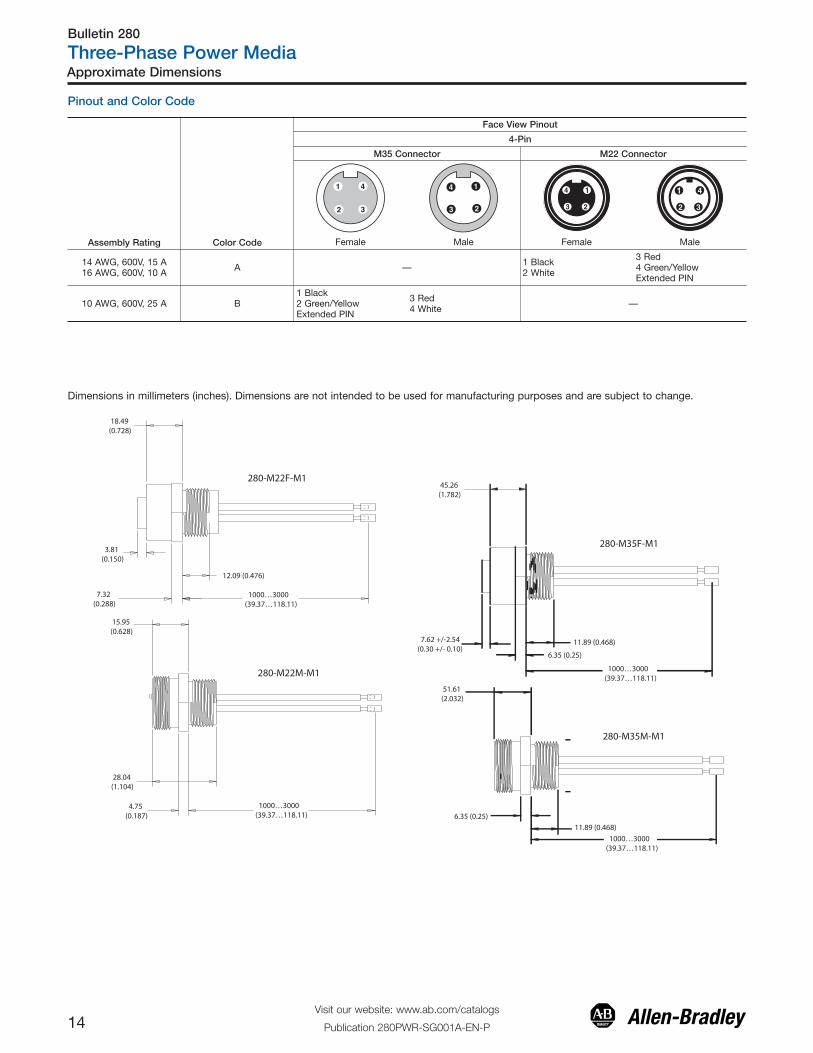
Pinout and Color Code
Assembly Rating Color Code
Face View Pinout
4-Pin
M35 Connector M22 Connector
Female Male Female Male
14 AWG, 600V, 15 A16 AWG, 600V, 10 A A — 1 Black
2 White
3 Red4 Green/Yellow Extended PIN
10 AWG, 600V, 25 A B1 Black 2 Green/Yellow Extended PIN
3 Red4 White —
1000…3000(39.37…118.11)
280-M22F-M1
280-M22M-M1
18.49 (0.728)
3.81 (0.150)
12.09 (0.476)
7.32 (0.288)
15.95 (0.628)
28.04 (1.104)
4.75 (0.187)
1000…3000(39.37…118.11)
280-M35F-M1
280-M35M-M1
45.26 (1.782)
7.62 +/-2.54 (0.30 +/- 0.10)
11.89 (0.468)
6.35 (0.25)
11.89 (0.468)
6.35 (0.25)
51.61 (2.032)
1000…3000(39.37…118.11)
1000…3000(39.37…118.11)

Bulletin 280
Three-Phase Power Media
15Visit our website: www.ab.com/catalogs
Publication 280PWR-SG001A-EN-P
Bulletin 280 ⎯ Three-Phase Power Field-InstalledReceptacles
� Listed per UL 2237 for use in motor branch circuits per NFPA 79� 16 to 10 AWG conductors� 4-pin configuration, M35 or M22 connection� Used to configure custom-length cordsets
Table of Contents
ApproximateDimensions................... 16Accessories.................. 21
Standards ComplianceUL 2237
CertificationsUL Listed (File No. E318496,Guide PVVA)
Product SelectionReceptacles
Pin Count Assembly Rating Certifications Cable Diameter
Cat. No.
Female Male
4-pin16 AWG, 600V, 10 A14 AWG, 600V, 15 A UL Listed UL 2237 (File No. E318496, Guide PVVA)
0.28…0.47 in. 280-FAM22F 280-FAM22M
10 AWG, 600V, 25 A♦ 0.48…0.81 in. 280-FAM35F 280-FAM35M
♦ When used with Cat. No. 280-PWRM24_-M* [E,F,G,or H], use Cat. No. 280-FAM35* and the corresponding mating receptacle 280-M35F-M*
Specifications
Mechanical
Insert Black PVC
Receptacle Shell Material Black anodized aluminum (female) and zinc diecast, black E-coat (male)
Electrical
Contacts Copper alloy with gold over nickel plating (Trunk), brass with gold over nickel plating (Drop)
Cable Rating 600V AC/DC: 14 AWG Listed TC, 16 AWG Listed TC-ER/STOOW, 10 AWG Listed TC-ER/STOOW
Assembly Rating Note: When applied with 14 AWG or larger wire, this issuitable for use on Motor Branch Circuits, per NFPA 79.
4-pin ⎯ 16 AWG, 600V @ 10 A4-pin ⎯ 14 AWG, 600V @ 15 A4-pin ⎯ 10 AWG, 600V @ 25 A
Short Circuit Current Rating(SCCR)
4-pin — 10 AWGFusing: Suitable for use on a circuit capable of delivering not more than 65 000 RMS symmetrical amperes at 600V AC
maximum when protected by CC, J, and T class fusesCircuit Breaker: Suitable for use on a circuit capable of delivering not more than 65 000 RMS symmetrical amperes at
480V AC maximum when protected by Bul. 140U-H frame circuit breaker, not rated more than 480V, 100 A and a maximuminterrupting of 65 000 RMS symmetrical amperes.
4-pin — 16 and 14 AWGFusing: Suitable for use on a circuit capable of delivering not more than 65 000 RMS symmetrical amperes at 600V AC
maximum when protected by CC, J, and T class fuses, rated 40 A non-time delay or 20 A time delay.Circuit Breaker: Suitable for use on a circuit capable of delivering not more than 45 000 RMS symmetrical amperes at
480V AC maximum when protected by Cat. No. 140U-D6D3-C30 circuit breaker, not rated more than 480Y/277V, 30 A, havingan interrupting rating not less than 45 000 RMS symmetrical amperes, 480Y/277V maximum.
Environmental
Enclosure Rating IP67, UL Type 4/12 & NEMA 6P; 1200 psi washdown
Pinout and Color Code
Assembly Rating
Face View Pinout
4-Pin
M35 Connector M22 Connector
Female Male Female Male
16 AWG, 600V, 10 A14 AWG, 600V, 15 A — 1 Black
2 White
3 Red4 Green/Yellow Extended PIN
10 AWG, 600V, 25 A1 Black 2 Green/Yellow Extended PIN
3 Red4 White —
Product Selection/Specifications

Bulletin 280
Three-Phase Power Media
16Visit our website: www.ab.com/catalogs
Publication 280PWR-SG001A-EN-P
Approximate Dimensions
M22, 16 AWG Field-Installed Receptacles
M35, 10 AWG Field-Installed Receptacles
Cat. No. 280-FAM22F (Female)
Cat. No. 280-FAM22M (Male)
Cat. No. 280-FAM35F (Female)
Cat. No. 280-FAM35M (Male)
3.63 in. 7/8-16 UN-2B
Ø 1.10 in.
7/8-16 UN-2B
Ø 1.10 in.
3.63 in.
1-3/8-16 UN-2A
4.40 in.
Ø 1.52 in.
1-3/8-16 UN-2A
4.40 in.
Ø 1.52 in.

Bulletin 889N
Control Power Media
17Visit our website: www.ab.com/catalogs
Publication 280PWR-SG001A-EN-P
Product Selection/Specifications/Approximate Dimensions
Product Selection
Specifications Pinout and Color Code
Face View Pinout
6-pin/5-used
Female Male
Color Code 1 Red (+)2 Black (-)3 Green (GND)
4 Blank/Not Used5 Blue (S1)6 White (S2)
Approximate DimensionsDimensions in millimeters (inches). Dimensions are not intended to be used for manufacturing purposes and are subject to change.
Female Straight
25.4(1.0) dia.
56.1 (2.21)
Female 90 Deg.
39.6 (1.56)
25.4(1.0) dia.
7/8 in.16 UN-2B
32.5(1.28)
Male Straight
Extended Pin 3
59.4 (2.34)
Male 90 Deg.
40.6 (1.6)
25.4(1.0) dia.
7/8 in.16 UN-2B
32.5(1.28) Example of Cordset
Example of Patchcord
Bulletin 889N ⎯ Control Power Trunk and Drop Cables
� 6-pin/5-used configuration to prevent mis-wiring with networkconnectors
� One-piece molded design� 16 AWG exposed run (TC-ER) rated cable
Cordsets
Pin Count Assembly Rating
Cat. No.
Straight Female Right-Angle Female Straight Male Right-Angle Male6-pin/5 used 16 AWG 600V, 10 A 889N-F65GF-� 889N-R65GF-� 889N-M65GF-� 889N-E65GF-�
� Replace symbol with code from the table below that represents the desired length:
Feet 6.5 16.4 32.8
Meters 2 5 10
Code 2 5 10
Patchcords
Pin Count Assembly Rating
Cat. No.
Straight FemaleStraight Male
Right-Angle FemaleStraight Male
Straight FemaleRight-Angle Male
Right-Angle FemaleRight-Angle Male
6-pin/5 used 16 AWG 600V, 10 A 889N-F65GFNM-� 889N-R65GFNM-� 889N-F65GFNE-� 889N-R65GFNE-�
�Replace symbol with code from the table below that represents the desired length:
Feet 3.3 6.5 9.8 16.4 32.8
Meters 1 2 3 5 10
Code 1 2 3 5 10
Mechanical
Coupling Nut Black epoxy coated zinc
Overmold Black Riteflex TPE
Insert Yellow Riteflex TPE
Contacts Brass/gold over palladium nickel
Cable Grey PVC, 16 AWG, dual rated UL TC/OpenWiring and STOOW
Cable Diameter 0.44 in. +/- 0.12 in. (11.18 mm +/- 0.5 mm)
Electrical
Cable RatingUL Type TC 600V 90 °C Dry 75 °C Wet, Open
Wiring or MTW 600V 90 °C or STOOW 105 °C 600V - CSA STOOW 600V FT2
Assembly Rating 600V, 10 A
Environmental
Enclosure Type Rating IP67, NEMA 6P, 1200 psi washdown
Operating Temperature -20…+90 °C (-4…+194 °F)
Table of Contents
Accessories.................. 21
Bulletin 898N
Control Power Media
18Visit our website: www.ab.com/catalogs
Publication 280PWR-SG001A-EN-P
Product Selection/Specifications/Approximate Dimensions
Product Selection
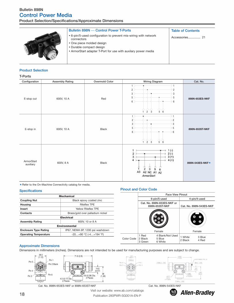
Bulletin 898N ⎯ Control Power T-Ports
T-Ports
Table of Contents
Accessories.................. 21� 6-pin/5-used configuration to prevent mis-wiring with networkconnectors
� One piece molded design� Durable compact design� ArmorStart adapter T-Port for use with auxilary power media
Configuration Assembly Rating Overmold Color Wiring Diagram Cat. No.
E-stop out 600V, 10 A Red
1
2
35
6
1
2
35
6
1 2 3 5 6
898N-653ES-NKF
E-stop in 600V, 10 A Black
123
5
6
123
5
6
1 2 3 5 6
898N-653ST-NKF
ArmorStartauxiliary 600V, 8 A Black 898N-543ES-NKF�
�Refer to the On-Machine Connectivity catalog for media.
Pinout and Color Code
Approximate DimensionsDimensions in millimeters (inches). Dimensions are not intended to be used for manufacturing purposes and are subject to change.
Pin 4
Pin 3
Pin 5Pin 1
Pin 2 Blank
Pin 6
28.5(1.12) 71.8 (2.8)
4.5 (0.17) Dia.2 Places
9.8 (0.38) Dia.2 Places
14.6(0.57)
38(1.49)
Cat. No. 898N-653ES-NKF or 898N-653ST-NKF Cat. No. 898N-543ES-NKF
Specifications
Mechanical
Coupling Nut Black epoxy coated zinc
Housing Riteflex TPE
Insert Yellow Riteflex TPE
Contacts Brass/gold over palladium nickel
Electrical
Assembly Rating 600V, 10 or 8 A
Environmental
Enclosure Type Rating IP67, NEMA 6P, 1200 psi washdown
Operating Temperature -20…+90 °C (-4…+194 °F)
Face View Pinout
6-pin/5-used 4-pin/4-used
Cat. No. 898N-653ES-NKF or898N-653ST-NKF Cat. No. 898N-543ES-NKF
Female Female
Color Code 1 Red 2 Black3 Green
4 Blank/Not Used5 Blue6 White
1 White2 Black
3 Blue4 Red

Bulletin 888N
Control Power Media
19Visit our website: www.ab.com/catalogs
Publication 280PWR-SG001A-EN-P
Product Selection/Specifications/Approximate Dimensions
� 6-pin/5-used configuration to prevent mis-wiring with networkconnectors
� 1/2 in. - 14 NPT threads
Product Selection
Specifications
Mechanical
Receptacle Shell Male: Black epoxy coated zinc diecastFemale: Black anodized aluminum
Insert Yellow PVC
Contacts Brass/gold over palladium nickel
Electrical
Assembly Rating 600V, 10 A
Environmental
Enclosure Type Rating IP67, NEMA 6P, 1200 psi washdown
Operating Temperature -20…+90 °C (-4…+194 °F)
Pinout and Color Code
Face View Pinout
6-pin/5-used
Female Male
Color Code 1 Red (+)2 Black (-)3 Green (GND)
4 Blank/Not Used5 Blue (S1)6 White (S2)
Approximate Dimensions
Dimensions in millimeters (inches). Dimensions are not intended to be used for manufacturing purposes and are subject to change.
Epoxy Filled
28.1 (1.11)
12.2 (0.48)1/2 in. 14 NPT Thread
7/8 in. 16 UNS-2Athread
4.78 (0.18)
152.4/203.2 (6.0/8.0)7/8 in. 16 UNS-2A
thread
3.81 (0.15)7.32 (0.28)
25.07(0.98)Dia.
30.5 (1.2)
11.1(0.44)
1/2 in. 14 NPT
177.8 (7.0)3.81 (0.15)
21.3 (0.84)Dia.
Bulletin 888N ⎯ Control Power Receptacles
Receptacles
Pin Count Assembly Rating
Cat. No.
Female Male6-pin/5 used 16 AWG 600V, 10 A 888N-D65AF1-� 888N-M65AF1-�
� Replace symbol with length in meters (0.3 or 1 standard)
Table of Contents
Accessories.................. 21

Bulletin 889A
Control Power Media
20Visit our website: www.ab.com/catalogs
Publication 280PWR-SG001A-EN-P
Product Selection/Specifications/Approximate Dimensions
� 6-pin/5-used configuration to prevent mis-wiring with networkconnectors
� 1/2 in. - 14 NPT threads
Product Selection
Specifications
Mechanical
Coupling Nut Black epoxy coated zinc
Overmold Riteflex TPE
Insert Yellow Riteflex TPE
Contacts Brass/gold over palladium nickel
Electrical
Assembly Rating 600V, 10 A
Environmental
Enclosure Type Rating IP67, NEMA 6P, 1200 psi washdown
Operating Temperature -20…+90 °C (-4…+194 °F)
Pinout and Color Code
Face View Pinout
6-pin/5-used
Female Male
Color Code 1 Red (+)2 Black (-)3 Green (GND)
4 Blank/Not Used5 Blue (S1)6 White (S2)
Approximate Dimensions
Dimensions in millimeters (inches). Dimensions are not intended to be used for manufacturing purposes and are subject to change.
25.4(1.0)Dia.
50.1 (1.97)
Bulletin 889A ⎯ Control Power Shorting Plugs
Shorting Plugs
Configuration Assembly Rating Overmold Color Wiring Diagram Cat. No.
E-stop out
600V, 10 A
Red
1.2.3.4.5.6.
N/C
N/C
N/C
Blank 889A-M65SP61
E-stop in Black
1.2.3.4.5.6.
N/C
N/C
N/C
Blank889A-M65SP65
Table of Contents
Accessories.................. 21
Bulletin 280, 888, 889, 898
Power Media
21Visit our website: www.ab.com/catalogs
Publication 280PWR-SG001A-EN-P
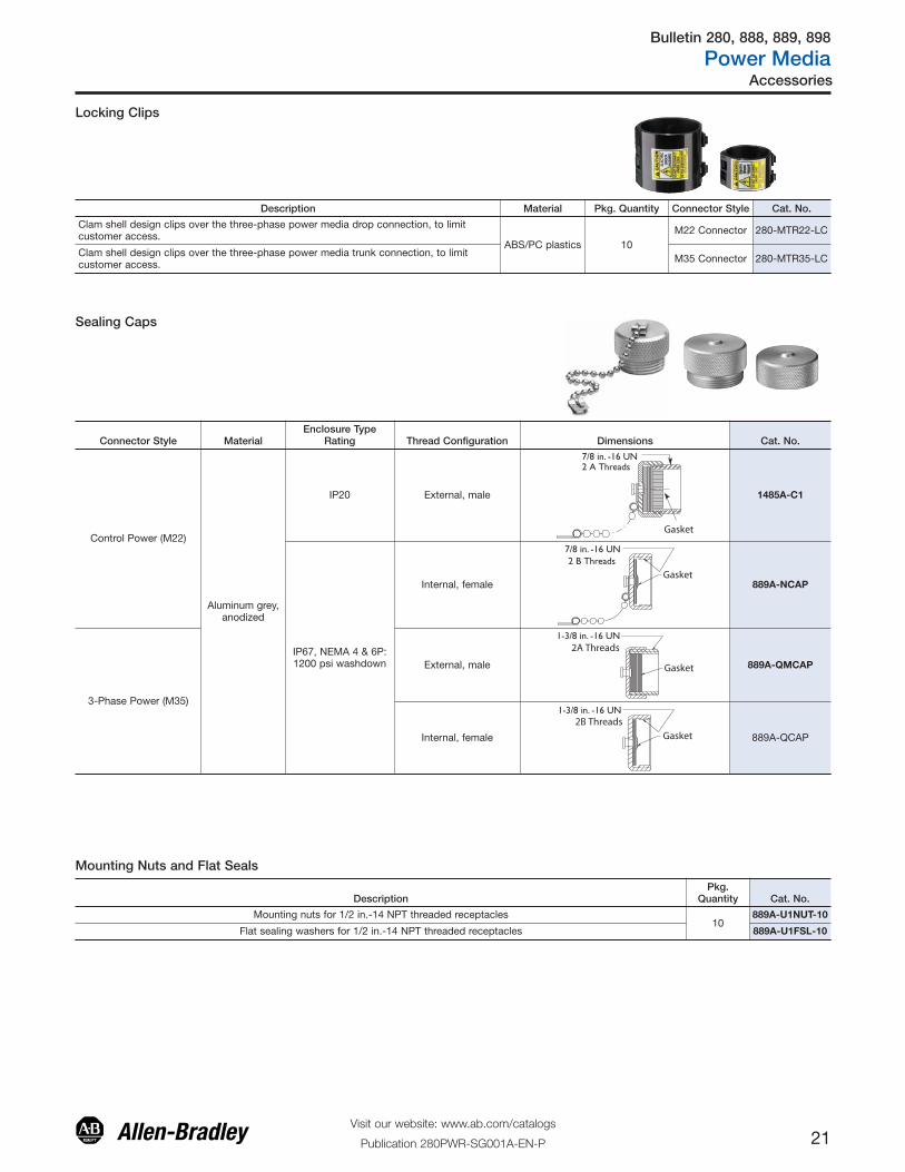
Accessories
Sealing Caps
Mounting Nuts and Flat Seals
DescriptionPkg.
Quantity Cat. No.
Mounting nuts for 1/2 in.-14 NPT threaded receptacles10
889A-U1NUT-10
Flat sealing washers for 1/2 in.-14 NPT threaded receptacles 889A-U1FSL-10
Locking Clips
Description Material Pkg. Quantity Connector Style Cat. No.
Clam shell design clips over the three-phase power media drop connection, to limitcustomer access.
ABS/PC plastics 10M22 Connector 280-MTR22-LC
Clam shell design clips over the three-phase power media trunk connection, to limitcustomer access. M35 Connector 280-MTR35-LC
Connector Style MaterialEnclosure Type
Rating Thread Configuration Dimensions Cat. No.
Control Power (M22)
Aluminum grey,anodized
IP20 External, male
7/8 in. -16 UN 2 A Threads
Gasket
1485A-C1
IP67, NEMA 4 & 6P:1200 psi washdown
Internal, female
7/8 in. -16 UN2 B Threads
Gasket889A-NCAP
3-Phase Power (M35)
External, male
1-3/8 in. -16 UN2A Threads
Gasket 889A-QMCAP
Internal, female
1-3/8 in. -16 UN2B Threads
Gasket 889A-QCAP
Bulletin 280, 888, 889, 898
Power Media
22Visit our website: www.ab.com/catalogs
Publication 280PWR-SG001A-EN-P
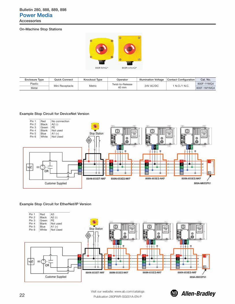
E-Stop Station
Customer Supplied
8
Customer Supplied
E-Stop Station
8
Accessories
On-Machine Stop Stations
Example Stop Circuit for DeviceNet Version
Pin 1Pin 2Pin 3Pin 4Pin 5Pin 6
RedBlackGreenBlankBlueWhite
No connectionA2 (-)PENot usedA1 (+)Not Used
Example Stop Circuit for EtherNet/IP Version
Pin 1Pin 2Pin 3Pin 4Pin 5Pin 6
RedBlackGreenBlankBlueWhite
A3A2 (-)PENot usedA1 (+)Not Used
Enclosure Type Quick Connect Knockout Type Operator Illumination Voltage Contact Configuration Cat. No.
PlasticMini Receptacle Metric Twist-to-Release
40 mm 24V AC/DC 1 N.O./1 N.C.800F-1YMQ4
Metal 800F-1MYMQ4

Bulletin 280, 888, 889, 898
Power Media
23Visit our website: www.ab.com/catalogs
Publication 280PWR-SG001A-EN-P
Notes
Publication 280PWR-SG001A-EN-P - November 2012 16Supercedes Publication 290-SG001B-EN-P — December 2011 Copyright © 2012 Rockwell Automation, Inc. All rights reserved. Printed in the U.S.A.
Rockwell Automation Support
Rockwell Automation provides technical information on the Web to assist you in using its products. At http://www.rockwellautomation.com/support/, you can find technical manuals, a knowledge base of FAQs, technical and application notes, sample code and links to software service packs, and a MySupport feature that you can customize to make thebest use of these tools.
For an additional level of technical phone support for installation, configuration, and troubleshooting, we offer TechConnect support programs. For more information, contact your local distributor or Rockwell Automation representative, or visit http://www.rockwellautomation.com/support/.
Installation Assistance
If you experience a problem within the first 24 hours of installation, review the information that is contained in this manual.You can contact Customer Support for initial help in getting your product up and running.
New Product Satisfaction Return
Rockwell Automation tests all of its products to ensure that they are fully operational when shipped from the manufacturing facility. However, if your product is not functioning and needs to be returned, follow these procedures.
Documentation Feedback
Your comments will help us serve your documentation needs better. If you have any suggestions on how to improve this document, complete this form, publication RA-DU002, available at http://www.rockwellautomation.com/literature/.
Trademark List
Allen-Bradley, ArmorConnect, ArmorStart LT, ControlLogix, CompactLogix, PowerFlex, RSLinx, StepLogic, DeviceLogix, On-Machine, RSNetWorx, and RSLogix 5000, are trademarks of Rockwell Automation, Inc. Trademarks not belonging to Rockwell Automation are property of their respective companies
United States or Canada 1.440.646.3434
Outside United States orCanada
Use the Worldwide Locator at http://www.rockwellautomation.com/support/americas/phone_en.html, or contactyour local Rockwell Automation representative.
United States Contact your distributor. You must provide a Customer Support case number (call the phone number above to obtainone) to your distributor to complete the return process.
Outside United States Please contact your local Rockwell Automation representative for the return procedure.
Rockwell Otomasyon Ticaret A.Ş., Kar Plaza İş Merkezi E Blok Kat:6 34752 İçerenköy, İstanbul, Tel: +90 (216) 5698400