argos3d – p100 -...
TRANSCRIPT

BLUETECHNIXEmbedding Ideas
Argos3D – P100
User Manual
Version 1.5

BLUETECHNIXEmbedding Ideas
© Bluetechnix 2013
Bluetechnix GmbH Waidhausenstraße 3/19 A-1140 Vienna AUSTRIA [email protected] www.bluetechnix.com
Argos®3D – P100 – User Manual
Document No.: 900-308 / A
Publication date: June 28, 2013
Applicable to: SDK release 2.2
Subject to change without notice. Errors excepted.
This document is protected by copyright. All rights reserved. No part of this document may be reproduced or transmitted for any purpose in any form or by any means, electronically or mechanically, without expressly written permission by Bluetechnix GmbH.
Windows is a registered trademark of Microsoft.

BLUETECHNIXEmbedding Ideas
© Bluetechnix 2013
Table of Contents
1 General Information .......................................................................................................................... 5
1.1 Symbols Used ........................................................................................................................... 5
1.2 CE Declaration .......................................................................................................................... 6
1.3 FCC Declaration ........................................................................................................................ 6
1.4 Eye Safety ................................................................................................................................. 6
Illumination: LEDs ................................................................................................................................ 6
Wavelength .......................................................................................................................................... 6
850nm (typ) .......................................................................................................................................... 6
In accordance with EN62471:2008 resp. IEC62471:2006 ................................................................... 6
Output power ....................................................................................................................................... 6
TBD ...................................................................................................................................................... 6
2 Overview ........................................................................................................................................... 7
2.1 In the box .................................................................................................................................. 7
2.2 Interfaces & Connectors ........................................................................................................... 7
3 Quick Start ....................................................................................................................................... 8
4 Hardware Installation ....................................................................................................................... 9
5 Software ......................................................................................................................................... 10
5.1 Demo Application .................................................................................................................... 10
5.2 Software Development Kit (SDK) ............................................................................................ 10
6 Camera Features ............................................................................................................................ 11
6.1 Camera Data Format ............................................................................................................... 11
6.2 Modulation Frequency ............................................................................................................ 11
6.3 Ambiguity Range ..................................................................................................................... 12
6.4 Frame-rate vs. Integration Time .............................................................................................. 12
6.5 External Trigger and Modulation Signal Interface .................................................................. 12
6.5.1 External Modulation Signal .............................................................................................. 12
6.5.2 External Hardware Trigger Signal .................................................................................... 12
7 Appendix ........................................................................................................................................ 13
7.1 Operating Conditions .............................................................................................................. 13
7.1.1 Input current..................................................................................................................... 13
7.2 Optical Characteristics ............................................................................................................ 14
7.3 Measurement Specifications .................................................................................................. 14
7.3.1 Measurement Environmental Conditions ........................................................................ 14
7.3.2 Typical Reproducibility .................................................................................................... 14
7.3.3 Typical Integration Time .................................................................................................. 16
7.3.4 Typical Range .................................................................................................................. 16

BLUETECHNIXEmbedding Ideas
© Bluetechnix 2013
7.3.5 Accuracy of Distances ..................................................................................................... 17
7.4 Environmental considerations ................................................................................................. 17
7.4.1 Case Temperature ........................................................................................................... 17
7.4.2 Integration Time vs. Frame-rate ...................................................................................... 18
7.5 Connector Description ............................................................................................................ 18
7.5.1 Modulation Light Interface (a) .......................................................................................... 18
7.5.2 USB Micro B Connector (b) ............................................................................................. 19
7.5.3 Power connector (c) ......................................................................................................... 19
7.5.4 Tripod Socket (d) ............................................................................................................. 20
7.5.5 Mounting Holes (h) ........................................................................................................... 20
7.6 Mechanical Outline ................................................................................................................. 20
7.7 Support ................................................................................................................................... 20
7.7.1 General Support ............................................................................................................... 20
7.8 Software Packages ................................................................................................................. 21
8 Product History .............................................................................................................................. 22
8.1 Version Information ................................................................................................................. 22
8.1.1 Argos3D – P100 ............................................................................................................... 22
8.2 Anomalies ................................................................................................................................ 22
8.3 Document Revision History .................................................................................................... 22
9 Index ............................................................................................................................................... 23

BLUETECHNIXEmbedding Ideas
© Bluetechnix 2013
© Bluetechnix GmbH 2013
All Rights Reserved.
The information herein is given to describe certain components and shall not be considered as a guarantee of characteristics.
Terms of delivery and rights of technical change reserved.
We hereby disclaim any warranties, including but not limited to warranties of non-infringement, regarding circuits, descriptions and charts stated herein.
Bluetechnix makes and you receive no warranties or conditions, express, implied, statutory or in any communication with you. Bluetechnix specifically disclaims any implied warranty of merchantability or fitness for a particular purpose.
Bluetechnix takes no liability for any damages and errors causing of the usage of this board. The user of this board is responsible by himself for the functionality of his application. He is allowed to use the board only if he has the qualification. More information is found in the General Terms and Conditions (AGB).
Information
For further information on technology, delivery terms and conditions and prices please contact Bluetechnix (http://www.bluetechnix.com).
Warning
Due to technical requirements components may contain dangerous substances.
BLUETECHNIXEmbedding Ideas
Argos3D – P100 - Argos3D – P100 Last change: 28 June 2013 Version 1.5
© Bluetechnix 2013 Page | 5
1 General Information
This guide applies to all smart cameras based on the Argos® smart camera platform from Bluetechnix GmbH. Follow this guide chapter by chapter to set up and understand your product. If a section of this document only applies to certain camera models, this is indicated at the beginning of the respective section.
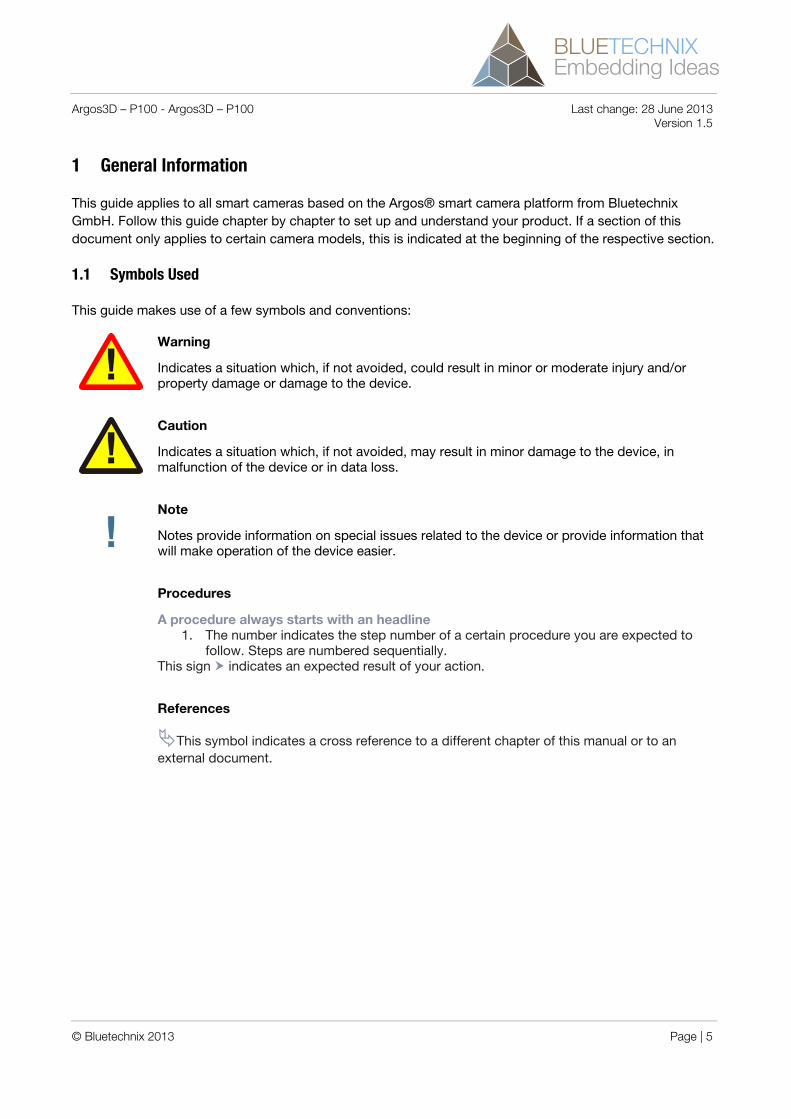
1.1 Symbols Used
This guide makes use of a few symbols and conventions:
Warning
Indicates a situation which, if not avoided, could result in minor or moderate injury and/or property damage or damage to the device.
Caution
Indicates a situation which, if not avoided, may result in minor damage to the device, in malfunction of the device or in data loss.
Note
Notes provide information on special issues related to the device or provide information that will make operation of the device easier.
Procedures
A procedure always starts with an headline1. The number indicates the step number of a certain procedure you are expected to
follow. Steps are numbered sequentially. This sign indicates an expected result of your action.
References
This symbol indicates a cross reference to a different chapter of this manual or to an external document.

BLUETECHNIXEmbedding Ideas
Argos3D – P100 - Argos3D – P100 Last change: 28 June 2013 Version 1.5
© Bluetechnix 2013 Page | 6
1.2 CE Declaration
Bluetechnix GmbH hereby declares that this Argo3D-P100 product is in compliance with the essential requirements and other relevant provisions of Directive 2004/108/EC.
(http://www.bluetechnix.com/goto/argos3d-p100)
1.3 FCC Declaration
This device complies with part 15 of the FCC rules. Operation is subject to the following two conditions: (1) this device may not cause harmful interference, and (2) this device must accept any interference received, including interference that may cause undesired operation.
This equipment has been tested and found to comply with the limits for a Class A digital device, pursuant to part 15 of the FCC Rules. These limits are designed to provide reasonable protection against harmful interference when the equipment is operated in a commercial environment. This equipment generates, uses, and can radiate radio frequency energy and, if not installed and used in accordance with the instruction manual, may cause harmful interference to radio communications. Operation of this equipment in a residential area is likely to cause harmful interference in which case the user will be required to correct the interference at his own expense.
(http://www.bluetechnix.com/goto/argos3d-p100)
FCC ID: SSZ-A3DP100150200Trade Name: Bluetechnix GmbHModel: Argos3D - P100
Classification of ITE (EN55022)
This is a class A product. In a domestic environment this product may cause radio interference in which case the user may be required to take adequate measures.
1.4 Eye Safety
Illumination: LEDs Wavelength 850nm (typ) In accordance with EN62471:2008 resp. IEC62471:2006
Output power TBD

BLUETECHNIXEmbedding Ideas
Argos3D – P100 - Argos3D – P100 Last change: 28 June 2013 Version 1.5
© Bluetechnix 2013 Page | 7
2 Overview
2.1 In the box
Argos3D - P100
Micro-USB Cable
5V/3A power supply*
Tripod
Quick Start Guide
2.2 Interfaces & Connectors
Figure 2-1: Argos3D – P100 views
a. Modulation Light Interface
b. USB Micro B Connector
c. Power Connector
d. Tripod Socket
e. Camera Window
f. IR LED Window
g. Cooling Plate
h. Mounting Holes (Use M4 screws for mounting the device to an additional heat sink)
* The socket-outlet shall be installed near the equipment and shall be easily accessible.
BLUETECHNIXEmbedding Ideas
Argos3D – P100 - Argos3D – P100 Last change: 28 June 2013 Version 1.5
© Bluetechnix 2013 Page | 8
3 Quick Start
Your Argos3D - P100 comes with a printed Quick Start Guide. Please follow this guide for your first installation. The Quick Started Guide can also be found on our support page:
Quick Start
https://support.bluetechnix.at/wiki/Argos%C2%AE3D_P100_Camera

BLUETECHNIXEmbedding Ideas
Argos3D – P100 - Argos3D – P100 Last change: 28 June 2013 Version 1.5
© Bluetechnix 2013 Page | 9
4 Hardware Installation
Caution
Cooling plate may become hot!
If the Argos3D - P100 is used without any additional heat sink attached to the cooling plate, the recommended minimum spacing between casing and surrounding is 10mm in each direction.
Note
By mounting the camera onto a heat sink, it’s allowed to decrease the recommended minimum spacing. In this case the customer is responsible for an adequate cooling.
Figure 4-1: Recommended minimum spacing for air circulation

BLUETECHNIXEmbedding Ideas
Argos3D – P100 - Argos3D – P100 Last change: 28 June 2013 Version 1.5
© Bluetechnix 2013 Page | 10
5 Software
5.1 Demo Application
For the first evaluation of the camera and to evaluate different settings and configurations a demo application is provided. The demo application can be downloaded from our support web site. Refer to the “Quick Start Guide” for more information and visit our support site.
Software and documentation
https://support.bluetechnix.at/wiki/Argos%C2%AE3D_P100_Camera
5.2 Software Development Kit (SDK)
To evaluate the camera and to integrate it in your own application a powerful software development kit is provided. The software development kit runs under Linux and Windows. Refer to our support site for downloading the SDK and for additional information and documentation.
Software and documentation
https://support.bluetechnix.at/wiki/Argos%C2%AE3D_P100_Camera

BLUETECHNIXEmbedding Ideas
Argos3D – P100 - Argos3D – P100 Last change: 28 June 2013 Version 1.5
© Bluetechnix 2013 Page | 11
6 Camera Features
6.1 Camera Data Format
The camera provides an array of depth data in meters and an array of grayscale values for each pixel. In addition also a 3D XYZ point-cloud is provided. The following image shows the coordinate system from a cameras point of view:
27,5mm
14mm
Optical axis
19199 1919
8
0
...
12
10mm
Figure 6-1: Argos-P100 Coordinate System
For information about the data and buffer format please refer to the software documentation site.
Support Link
https://support.bluetechnix.at/wiki/Argos%C2%AE3D_P100_Camera
6.2 Modulation Frequency
The modulation frequency is set to 30 MHz per default. Other modulation frequencies can be set using the SDK. Be aware that this changes also the ambiguity range of the camera. Refer to our software documentation to see how to change the modulation frequency.
BLUETECHNIXEmbedding Ideas
Argos3D – P100 - Argos3D – P100 Last change: 28 June 2013 Version 1.5
© Bluetechnix 2013 Page | 12
Software and documentation
https://support.bluetechnix.at/wiki/Argos%C2%AE3D_P100_Camera
6.3 Ambiguity Range
The ambiguity range of the camera is per default approximately 5m. If you have objects which are more than 5 meters away from the camera, they will be shown as to be very close to the camera. If you need an enhancement of the ambiguity range without changing the modulation frequency please contact our support team at [email protected].
6.4 Frame-rate vs. Integration Time
The camera integration time is limited by default to 2.7ms. It can be enhanced by using the command DisableIntegrationTimeCheck (Refer to 7.7.1).
Caution
Be careful when disabling the integration time limit. Higher integration times may require enhanced cooling. Be aware to provide enough cooling in that case! (Refer to 7.4.2).
6.5 External Trigger and Modulation Signal Interface
6.5.1 External Modulation Signal
The camera provides an external connector (refer to 7.5.1) where the modulation signal is provided as LVDS signal to synchronize with an external light source. This signal must be enabled by software before it can be used. Please refer to our software documentation (see 7.7.1) to see how to activate the external modulation signal.
6.5.2 External Hardware Trigger Signal
The camera provides an external connector (Refer to 7.5.1) where a hardware trigger can be applied. The hardware trigger must be enabled by software. Please refer to our software documentation (see 7.7.1) to see how to enable the hardware trigger. Refer to 7.5.1 for the signal description.

BLUETECHNIXEmbedding Ideas
Argos3D – P100 - Argos3D – P100 Last change: 28 June 2013 Version 1.5
© Bluetechnix 2013 Page | 13
7 Appendix
7.1 Operating Conditions
Symbol Parameter Min Typical Max UnitVIN Input supply voltage 4.9 5.0 5.2 VIIN Input current 1) TBD 900 1) TBD mATOP Operating Temperature 0 +552) °CTSTG Storage Temperature -40 +125 °CFITP3) Frame-rate Integration Time Product 550
Table 1: Operating Conditions
Note
Valid for a frame-rate of 40fps and an integration time of 1500μs. The input current depends on the applied frame-rate and integration time. Please refer to 7.1.1.
Note
The maximum operating temperature depends on the frame-rate and integration time. Refer to Figure 2-1 for recommended integration time to frame-rate combinations. The specified max. temperature is in combination with an external heat sink (which is not part of the original delivery box refer to chapter 2.1 above) dimension 61 x 58 x 36 (L x W x H) and specified heat conductance value of minimum. 2.2 K/W.
Warning
Furthermore, the operating temperature can be increased to max. +65°C with an extra-large sized heat sink. Precautions must be taken to protect the heat sink by touching because of exceeding heat sink temperature higher than +70°C (max. allowed temperature of external surfaces of equipment that may be touched).
Note
Refer to 7.4.2 for valid frame-rate to integration time combinations.
7.1.1 Input current
The input current depends on the selected frame-rate (fps) and the integration time (tINT). The following figure shows typical values. The values for the x axis shows the Frame-rate Integration Time Product (FITP) which is calculated as follow:
∙ 1∙ 4

BLUETECHNIXEmbedding Ideas
Argos3D – P100 - Argos3D – P100 Last change: 28 June 2013 Version 1.5
© Bluetechnix 2013 Page | 14
Figure 7-1: Input current depending on frame-rate integration time product
7.2 Optical Characteristics
Symbol Parameter Min Typical Max Unit#LEDs Nr. of LEDs 2 ΛCENTROID Centroid-Wavelength of Illumination 850 nm∆λ Spectral Bandwidth 30 nmIe Radiant intensity W/srFoVH Horizontal Field of View 90 DegFoVV Vertical Field of View 67,5 Deg
Table 2: Optical Characteristics
7.3 Measurement Specifications
7.3.1 Measurement Environmental Conditions
All the following measurements have been acquired at the following constant environmental conditions.
Parameter Value Temperature 23 °C Humidity 35 % Ambient light 2 kLux Modulation Frequency 30 MHz Frame-rate 15 fps
Table 3: Environmental Specification
7.3.2 Typical Reproducibility
The following table shows the standard deviation over 100 samples.
Measuring range [mm]
White target (90%) [mm]
Integration time [ms]
Gray target (18%) [mm]
Integration time [ms]
100 ±1,5 0,5 300 ±0,5 0,5 ±1,5 0,5 500 ±1 0,5 ±3 0,5
0
0.5
1
1.5
2
2.5
3
0 200 400 600 800 1000
Inp
ut C
urre
nt [A
]
Frame-rate Integration Time Product

BLUETECHNIXEmbedding Ideas
Argos3D – P100 - Argos3D – P100 Last change: 28 June 2013 Version 1.5
© Bluetechnix 2013 Page | 15
Measuring range [mm]
White target (90%) [mm]
Integration time [ms]
Gray target (18%) [mm]
Integration time [ms]
700 ±2 0,5 ±3 1,0 900 ±3,5 0,5 ±7 1,0 1100 ±2,5 1,0 ±7 1,5 1300 ±3,5 1,0 ±11 1,5 1500 ±5 1,0 ±11 2,0 1700 ±5 1,5 ±12 5,0 1) 1900 ±5 1,5 ±14 5,01) 2100 ±6,5 1,5 ±14 10,01) 2300 ±6,5 2,0 ±15 10,01) 2500 ±9 2,0 ±23 10,01) 2700 ±10 2,0 ±31 10,01) 2900 ±14 2,0 ±49 10,01)
Table 4: Typical Reproducibility
1) Note The integration time limit can be disabled with the source command DisableIntegrationTimeCheck. Otherwise the max integration time is limited to 2,7ms. Refer to our support internet site for information how to apply this command (see 7.7.1).

BLUETECHNIXEmbedding Ideas
Argos3D – P100 - Argos3D – P100 Last change: 28 June 2013 Version 1.5
© Bluetechnix 2013 Page | 16
7.3.3 Typical Integration Time
Measuring range [mm] Integration time for white target (90%) [ms]
Integration time for gray target (18%) [ms]
500 1,0 1,01000 1,0 1,51500 1,5 2,02000 1,5 3,02500 2,0 5,0 1)
3000 2,5 10,0 1)
Table 5: Typical Integration Time
7.3.4 Typical Range
Integration time [ms]
Minimum distance for white target (90%) [mm]
Maximum distance for white target (90%) [mm]
Minimum distance for gray target (18%) [mm]
Maximum distance for gray target (18%) [mm]
0,5 300 1500 100 500 1,0 300 2000 100 1000 1,5 300 2000 300 1500 2,0 500 3000 1) 300 2000 2,5 500 3000 1) 300 2000 3,0 1) 500 3000 1) 300 2000 5,0 1) 500 4000 1) 300 3000 1) 10,0 1) 500 6000 1) 500 3000 1)
Table 6: Typical Range
1) Note
The integration time limit can be disabled with the source command DisableIntegrationTimeCheck. Otherwise the max integration time is limited to 2,7ms. Refer to our support internet site for information how to apply this command (see 7.7.1).

BLUETECHNIXEmbedding Ideas
Argos3D – P100 - Argos3D – P100 Last change: 28 June 2013 Version 1.5
© Bluetechnix 2013 Page | 17
7.3.5 Accuracy of Distances
The following table has been determined by calibrating the device at a distance of 1500mm and an integration time of 1,5ms. For applications with specific environment optimized calibration may improve the error results.
Measuring range [mm]
White target (90%) [mm]
Integration time [ms] Gray target (18%) [mm]
Integration time [ms]
500 ±5 1,0 ±10 1,0 1000 ±1 1,0 ±1 1,5 1500 ±1 1,5 ±5 2,0 2000 ±1 1,5 ±10 3,0 1) 2500 ±20 2,0 ±25 5,0 1) 3000 ±20 2,5 ±80 10,0 1)
Table 7: Accuracy of Distances
1) Note
The integration time limit can be disabled with the source command DisableIntegrationTimeCheck. Otherwise the max integration time is limited to 2,7ms. Refer to our support internet site for information how to apply this command (see 7.7.1).
7.4 Environmental considerations
7.4.1 Case Temperature
The following figure shows the expected case temperature depending on the frame-rate and integration time product (FITP). The values for the x axis are calculated as follow:
∙ 1∙ 4
Figure 7-2: Expected case temperature depending on frame-rate integration time product (FITP)
0
10
20
30
40
50
60
70
0 200 400 600 800 1000
Cas
e Te
mp
erat
ure
[°C
]
Frame-rate Integration Time Product
Environment temperature25°C
Environment temperature45°C

BLUETECHNIXEmbedding Ideas
Argos3D – P100 - Argos3D – P100 Last change: 28 June 2013 Version 1.5
© Bluetechnix 2013 Page | 18
7.4.2 Integration Time vs. Frame-rate
The following table shows recommended frame-rate integration time combinations depending on the environment temperature.
Figure 7-3: Integration Time vs Frame-rate
The limit of the frame-rate and integration time combinations is given by the Frame-rate Integration Time Product (FITP) which
is calculated as follow: ∙ ∙ 4.
The maximum possible FITP at 25°C for the Argos-P100 is 550!
Caution
Be careful to not stress the device beyond the limits, otherwise you may damage the device.
7.5 Connector Description
7.5.1 Modulation Light Interface (a)
Mating Connector Type: MQ172X-4SA-CV
The Modulation Light Interface provides the modulation signal for an external illumination module (differential LVDS, 3V).
Caution
Overvoltage on the Modulation Light Interface will destroy the Argos3D - P100.
Pin No. Signal Name Power Domain Type Description 1 HARDWARE_TRIGGER 1) 3V I Camera trigger input

BLUETECHNIXEmbedding Ideas
Argos3D – P100 - Argos3D – P100 Last change: 28 June 2013 Version 1.5
© Bluetechnix 2013 Page | 19
Pin No. Signal Name Power Domain Type Description 2 EXT.MOD_N 3V DP Modulation signal output-3 EXT.MOD_P 3V DP Modulation signal output+4 SGND - PWR Ground
Table 8: Modulation Light Interface
7.5.1.1 Timing diagram of the Hardware-Trigger signal
tLAT
tPHtPL
HW
trig
ge
r e
dge
Illumination modulation signal
Figure 7-4: Timing diagram of the hardware trigger signal
Timing value Description Min Typical Max UnittPL Pulse Low Time before Trigger 50 nstPH Pulse High Time 50 nstLAT Trigger Edge to Frame Capture Latency TBD 60 TBD μs
Table 9: Timing specification for the hardware trigger signal
7.5.2 USB Micro B Connector (b)
A standard micro USB B Connector is used for connecting the Argos3D - P100 to a host computer.
7.5.3 Power connector (c)
Connector Type: 2.1mm ID / 5.5mm OD
Polarity:
Note
Only use the provided power supply.
The socket-outlet shall be installed near the equipment and shall be easily accessible

BLUETECHNIXEmbedding Ideas
Argos3D – P100 - Argos3D – P100 Last change: 28 June 2013 Version 1.5
© Bluetechnix 2013 Page | 20
7.5.4 Tripod Socket (d)
A ¼ inch tripod socket can be placed on the bottom of the Argos3D - P100.
7.5.5 Mounting Holes (h)
There are four M4 mounting holes on the backside of the Argos3D - P100, for mounting the camera onto a heat sink.
7.6 Mechanical Outline
All dimensions are given in mm.
Figure 7-5: Mechanical Outline
7.7 Support
7.7.1 General Support
General support for products can be found at Bluetechnix’ support site
Support Link
https://support.bluetechnix.at/wiki/Argos%C2%AE3D_P100_Camera

BLUETECHNIXEmbedding Ideas
Argos3D – P100 - Argos3D – P100 Last change: 28 June 2013 Version 1.5
© Bluetechnix 2013 Page | 21
7.8 Software Packages
Software packages and software downloads are for registered customers only
Software Package
https://support.bluetechnix.at/wiki/Argos%C2%AE3D_P100_Camera

BLUETECHNIXEmbedding Ideas
Argos3D – P100 - Argos3D – P100 Last change: 28 June 2013 Version 1.5
© Bluetechnix 2013 Page | 22
8 Product History
8.1 Version Information
8.1.1 Argos3D – P100
Version Release date Firmware Version1.0.0 April 2013 26022013
Table 10: Overview Argos3D – P100 product changes
8.2 Anomalies
Applies to Date Description Hardware V1.0 and Firmware Version 26022013
2013 02 14 Setting a register in the camera will have a latency of approximately 100ms to 200ms. During this time the camera stops capturing frames.
Hardware V1.0 and Firmware Version 26022013
2013 02 14 Reducing the frame-rate using the SetPhaseTime command may increase motion artifacts.
Table 11 – Product anomalies
8.3 Document Revision History
Version Date Document Revision 1 2013 02 14 First release V1.0 of the Document2 2013 03 14 Temperature tables added; 3D coordinate figures added; current
consumption added; Some minor changes; 3 2013 03 26 Added Class A note.4 2013 04 19 Added storage temperature added; added optical characteristics; some
changes to chapter “Frame-rate vs. Integration Time”; some typos corrected.
5 2013 05 23 Added safety information, thermal resistance, heat sink information
Table 12: Revision history

BLUETECHNIXEmbedding Ideas
Argos3D – P100 - Argos3D – P100 Last change: 28 June 2013 Version 1.5
© Bluetechnix 2013 Page | 23
9 Index
A
Accuracy Distances ................................................................ 17
Air circulation Minimum Spacing ..................................................... 9
Anomalies ................................................................... 22
C
Camera Data Format ................................................... 11 CE
Declaration ................................................................ 6 Contents
Package Contents ..................................................... 7 Cooling
Heat sink ................................................................... 9 Current
Input ........................................................................ 13
E
External Trigger ........................................................... 12
F
FCC Declaration ................................................................ 6
H
Hardware-Trigger Timing diagram ....................................................... 19
I
Integration Time Typical Values ......................................................... 16
Interfaces Connectors................................................................ 7
M
Measurement Specifications .......................................................... 14
Modulation Frequency ................................................ 11 Modulation Light Interface
Connector Description ............................................ 18 Modulation Signal Interface ......................................... 12 Mounting Holes ........................................................... 20
O
Operating Conditions Environmental Conditions ....................................... 13
Outline Mechanical .............................................................. 20
P
Power Connector ............................................................... 19
Q
Quick Start Getting Started .......................................................... 8
R
Range Typical ..................................................................... 16
S
Software ...................................................................... 10 Software Development Kit
SDK ......................................................................... 10 Spacing
Minimum distance ..................................................... 9 Support ....................................................................... 20

BLUETECHNIXEmbedding Ideas
Argos3D – P100 - Argos3D – P100 Last change: 28 June 2013 Version 1.5
© Bluetechnix 2013 Page | 24
T
Temperature Case, Housing ......................................................... 17
Tripod .......................................................................... 20
V
Version Product History ....................................................... 22