© arema 2014 1 · pdf filethe organic coatings consisted of a high performance exterior...
TRANSCRIPT

Coatings to Control Solar Heat Gain on Rails
Dr. George W. Ritter EWI*
*1250 Arthur E. Adams Drive Columbus, OH 43221
[email protected] 614-688-5199
Leith Al-Nazer
Federal Railroad Administration 1200 New Jersey Avenue, SE
Washington, DC 20590 [email protected]
202-493-6128
Number of words: 7253 (including allowance for 11 Figs and 2 Tables) ABSTRACT
Rail exposed to solar radiation increases in temperature from radiant solar heating. This results from absorption at
near infrared (NIR) wavelengths of ~1-3 micrometers ().
Welded rails are typically installed with a target neutral rail temperature (NRT) of 85-95oF. As rail temperature increases, stresses build from thermal expansion producing track distortion (sun kink). As a precaution, railroads commonly issue slow orders when the measured or estimated rail temperature could reach 120-130oF. FRA data analyses have shown that many track buckles occur near a fixed structure. In general, if rail solar gain can be reduced, it may be possible to decrease the number of track buckle incidents.
NIR reflective coatings to reduce solar absorption in the 1-3 range are in use on civil structures. Most are based on paints with filler additives. Certain ceramic like coatings are also capable of reflecting NIR light, and coatings for spacecraft are effective on satellites or re-entry vehicles.
Products representing all three approaches have been investigated in this program for the potential: (1) to keep rail temperature at least 10oF cooler or (2) control overall temperature gain to <30oF compared with untreated rail. The products were measured for natural NIR reflectance on instruments, then by measuring temperature gain of coated steel plates irradiated with a natural NIR spectrum lamp, and finally by monitoring temperatures on exposed short rail sections. Predicted thermal performance and actual performance based on exposed, treated rails were compared. Some coatings were effective in reducing thermal gain to desirable ranges.
INTRODUCTION
Solar thermal gain on rails can result in a lateral buckling of track referred to as sun kink. Typically, these result in sliding of a track section, shifting of ties, and a distorted segment of rail. Sun-kinked rails can be deformed enough to result in train derailment, or to require substantial speed reductions (“slow orders”) through the affected area. A recent FRA report (1) cites recent trends of $15-20 million/year in direct physical damages caused by sun kinks. The cost of slowdowns is potentially greater because of traffic delays.
FRA studies (1) have shown a linear correlation between rail temperature and the number of derailments when air
temperatures exceed 85F. Typically, rail is installed with an assumed track temperature of 90F for calculating expansion and contraction due to weather conditions. If the rail temperature approaches, or is predicted to approach
140F, sun kink may be imminent due to expansion forces. For safety purposes, the railroads apply a rule of thumb
© AREMA 2014 1

and add 30F to the expected maximum temperature for the day. If that number exceeds 120F, the railroads often impose slow orders as a precaution. As a further precaution, those orders may be imposed over a wide timespan, perhaps from 8 A.M. to 8 P.M., even if peak temperature is expected at 3 P.M., for example. Thus, the imputed cost due to slow orders and justifiable caution is large, but difficult to calculate.
Effective reduction of rail temperature by 10F or prevention of temperature increase beyond 30oF cuold have a significant impact economically. It can help in preventing sun kinks outright, and allow the railroads to reduce slow-order time windows with the assurance that safety will be maintained.
TECHNICAL BACKGROUND
Heat control coating technologies are commercially available and used on roofs, building sides, glass, aircraft, and spacecraft to reduce heat gain from sunlight. Coatings for civil engineering structures are simple and relatively inexpensive, while those used in aerospace are quite sophisticated and costly. The FRA has developed weather-based modeling software for predicting rail temperature excursions within a given geographical area. The core of this software is based on fundamental thermal analysis theory that can predict rail temperature based on input parameters. Coupled with the hardware for examining the rail system, this software is implicitly described in a patent (2).Therefore, the technologies and the means to assess them exist, but an acceptable coatings package(s) for rail acceptance has not been identified or accepted. The technical innovation proposed in this program is to examine available coatings and additives for heat rejection on steels to provide railroads with alternatives for use.
PROGRAM OBJECTIVE and EXPERIMENTAL APPROACH
Program Objectives
The objectives are to investigate thermal control coatings for rail. Identify those that demonstrate the potential to
reduce sun-gain rail temperature by 10F versus untreated rail or to prevent a temperature increase of >30oF for treated rail.
Program Experimental Approach
The program had two tasks:
Task 1 - Several commercial coatings and additives were investigated for their potential to reduce heat gain on steel. These materials featured high reflectivity or emissivity at infrared wavelengths. Commercially-available coatings were obtained for testing of infrared reflectivity in the range of 1 – 3���Task 1). A down selection of coating candidates was made based on infrared reflectance testing and measured thermal performance on coated steel plates.
Task 2 - Rail segments were coated, instrumented with thermocouples, and placed outdoors in a minimally shaded area for continuous exposure. Total exposure time was about five months in a climate ranging from late spring snow to summer heat in central Ohio (latitude = 40oN). Temperature data were recorded and analyzed for comparative performance ratings of the coatings.
DESCRIPTION OF EXPERIMENTAL WORK
Coating Selection
Many types of coatings are available for heat reflection. Some are based on paints that have been modified with reflective materials such as fillers or pigments. Those are classified as organic coatings in this work. Others contain high levels of heat-reflective ceramic powders and lower organic binder content or are completely inorganic, having no polymer binder resin. For this work, those are classified as inorganic coatings.
© AREMA 2014 2
The organic coatings consisted of a high performance exterior latex paint, pigmented tan, and the same material, pigmented gray by the vendor. Both are for use in outdoor architectural painting of metals. Those were designated as Exterior latex – tan and Exterior latex – gray. There were also two commercial roof and building coatings, sold specifically for thermal reflection on civil engineering structures. Those are designated as Rooftop-1and Roof top-2.
The organic + inorganic coatings were prepared by adding reflective microballoons to both the tan and gray exterior latex paints. As provided by the vendor, the microballoons are pre-weighed to be added and stirred into 1-gallon or 5-gallon pails of any paint. They can be admixed on site, if desired. The microballoon product was developed under a NASA contract for heat reflective coatings on space vehicles.
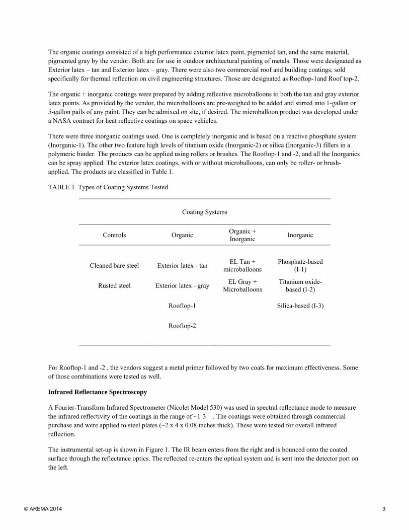
There were three inorganic coatings used. One is completely inorganic and is based on a reactive phosphate system (Inorganic-1). The other two feature high levels of titanium oxide (Inorganic-2) or silica (Inorganic-3) fillers in a polymeric binder. The products can be applied using rollers or brushes. The Rooftop-1 and -2, and all the Inorganics can be spray applied. The exterior latex coatings, with or without microballoons, can only be roller- or brush-applied. The products are classified in Table 1.
TABLE 1. Types of Coating Systems Tested
Coating Systems
Controls Organic Organic + Inorganic
Inorganic
Cleaned bare steel Exterior latex - tan EL Tan +
microballoons Phosphate-based
(I-1)
Rusted steel Exterior latex - gray EL Gray +
Microballoons Titanium oxide-
based (I-2)
Rooftop-1
Silica-based (I-3)
Rooftop-2
For Rooftop-1 and -2 , the vendors suggest a metal primer followed by two coats for maximum effectiveness. Some of those combinations were tested as well.
Infrared Reflectance Spectroscopy
A Fourier-Transform Infrared Spectrometer (Nicolet Model 530) was used in spectral reflectance mode to measure the infrared reflectivity of the coatings in the range of ~1-3 �. The coatings were obtained through commercial purchase and were applied to steel plates (~2 x 4 x 0.08 inches thick). These were tested for overall infrared reflection.
The instrumental set-up is shown in Figure 1. The IR beam enters from the right and is bounced onto the coated surface through the reflectance optics. The reflected re-enters the optical system and is sent into the detector port on the left.
© AREMA 2014 3

Figure 1. Infrared Reflectance Test Set-Up
Thermal Testing of Coated Steel Plates
Fully-Coated Plates
After the infrared analyses, selected coatings were applied to steel plates (8 x 12 x 3/4-inches thick). Surfaces were cleaned but not grit blasted. The inorganic coatings were applied by their respective vendors. The organic coatings were applied using spray or roller techniques, depending on perceived ease of application.
Each coated plate was placed, coating side up, under a solar spectrum infrared lamp (ExoTerra PT2144). The lamp has a power of 120 watts and is designed for use in artificial sun environments for terrariums and reptile habitats. The lamp was positioned about 7” above the panel surface. The test ran for 24 hours nominal with the temperature being sampled and recorded once a minute. The test set-up is shown in Figure 2.
Beam Entry Sample Plate Reflectance
Optics Beam Exit
© AREMA 2014 4

Figure 2. Set-Up for Testing Solar Gain of Coated Plates (left) and with Lamp Energized (right).
Partially-Coated Plates
In a variation of this test, two of the coatings (Exterior latex – tan, and Inorganic-2) were selected for a series of tests where coating was selectively removed to expose the plate. Baseline runs were made. Then, coating was removed to expose 10%, 25%, 50%, and 75% of the plate. The lamp exposure was elevated to 10” distance and angled at about 45o from the side so it did not radiate directly on the center of the plate. Temperatures were recorded as before and then compared with the results for fully-coated plates.
Preparation of Rail Samples for Outdoor Testing
Six 4-foot rail sections were prepared for outdoor testing. First, five thermocouples were affixed to each rail in different locations. A small divit, about 1/8-inch deep, was drilled into the selected locations and the thermocouples were potted into place using an epoxy adhesive, modified for enhanced thermal conductivity. The purpose was to provide good thermal contact between the thermocouple and the metal.
The thermocouples were affixed before any treatments so the coatings would help protect them from solar gain as well. The placement of the thermocouples is shown diagrammatically in Figure 3. On the east-facing side (right below), they were placed at the web centerline and one foot back on the flange. On the west-facing side, they were placed at the railhead side center, web centerline, and one foot forward on the flange.
Figure 3. Placement of Five Thermocouples on Coated Rails
© AREMA 2014 5
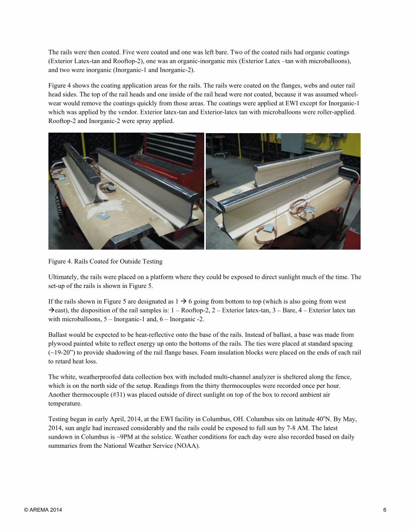
The rails were then coated. Five were coated and one was left bare. Two of the coated rails had organic coatings (Exterior Latex-tan and Rooftop-2), one was an organic-inorganic mix (Exterior Latex –tan with microballoons), and two were inorganic (Inorganic-1 and Inorganic-2).
Figure 4 shows the coating application areas for the rails. The rails were coated on the flanges, webs and outer rail head sides. The top of the rail heads and one inside of the rail head were not coated, because it was assumed wheel-wear would remove the coatings quickly from those areas. The coatings were applied at EWI except for Inorganic-1 which was applied by the vendor. Exterior latex-tan and Exterior-latex tan with microballoons were roller-applied. Rooftop-2 and Inorganic-2 were spray applied.
Figure 4. Rails Coated for Outside Testing
Ultimately, the rails were placed on a platform where they could be exposed to direct sunlight much of the time. The set-up of the rails is shown in Figure 5.
If the rails shown in Figure 5 are designated as 1 6 going from bottom to top (which is also going from west east), the disposition of the rail samples is: 1 – Rooftop-2, 2 – Exterior latex-tan, 3 – Bare, 4 – Exterior latex tan with microballoons, 5 – Inorganic-1 and, 6 – Inorganic -2.
Ballast would be expected to be heat-reflective onto the base of the rails. Instead of ballast, a base was made from plywood painted white to reflect energy up onto the bottoms of the rails. The ties were placed at standard spacing (~19-20”) to provide shadowing of the rail flange bases. Foam insulation blocks were placed on the ends of each rail to retard heat loss.
The white, weatherproofed data collection box with included multi-channel analyzer is sheltered along the fence, which is on the north side of the setup. Readings from the thirty thermocouples were recorded once per hour. Another thermocouple (#31) was placed outside of direct sunlight on top of the box to record ambient air temperature.
Testing began in early April, 2014, at the EWI facility in Columbus, OH. Columbus sits on latitude 40oN. By May, 2014, sun angle had increased considerably and the rails could be exposed to full sun by 7-8 AM. The latest sundown in Columbus is ~9PM at the solstice. Weather conditions for each day were also recorded based on daily summaries from the National Weather Service (NOAA).
© AREMA 2014 6

Figure 5. Placement of Rails on Test Platform
RESULTS and DISCUSSION
Reflectance Infrared Spectroscopy
This technique is simple and enabled some sorting of the coatings relative to thermal performance. The spectrometer measures reflectance at 60o incident and reflective angle. The difference between the infrared energy going in and the energy detected after reflection is considered to be the net infrared absorption for the material. However, if light is scattered at other angles, it may not be detected, and that energy is also assumed to be absorbed because the detector does not see it. As a result, scattered energy can give a false impression of poor performance when it probably enhances performance.
An overlay of multiple NIR reflectance scans for the coatings tested is shown in Figure 6.
1
6
© AREMA 2014 7

Figure 6. Relative Infrared Absorption as Predicted by Reflectance IR Spectroscopy
The main area of interest is the absorption from 0.9 ~1.4 (far left portion). A higher indicated absorption
suggests the material is not reflecting NIR radiation as well. There are clusters of absorption from 2.5 3(far
right), 1.8 2 (center) and 1.2 1.4 (left of center). Those are absorptions for water, organic hydrocarbon, and the water absorption overtone, respectively. The water is from water vapor in the air and would be present in the atmosphere, not affecting rail heat absorption. However, the absorption from hydrocarbon (center) is present in any coating with a high organic content, such as a paint or modified paint. Because this still falls in the spectral range for thermal gain of the rail, organic paints may be at a disadvantage for overall thermal performance since their reflective performance must overcome their natural absorption to be effective.
From this initial NIR analysis, the best coatings were predicted to be the Rooftop-1 (lowest trace) and the Exterior latex – gray with microballoons. Near the middle are the Exterior latex- tan with microballoons and Rooftop - 2 Near the top (predicted worst performance) were bare steel and rusted steel, which are about equal, and Inorganic coating-1. As it happens, testing on the coated steel plates under the lamp confirmed some, but not all of these results.
Solar Spectral Testing on Coated Plates
Fully-Coated Plates
The temperature reduction results for the fully-coated panels are given in Table 2 with the same data presented graphically in Figure 7. Cut-off lines for the desired performance windows are also shown in Figure 7.
© AREMA 2014 8

TABLE 2. Temperature Reductions (oF) for the Fully-Coated Steel Plates
Coating Temperature Reduction vs. Bare
Steel (oF)
Inorganic-3 -19.3
Inorganic-2 -14.2
Inorganic-1 -9.9
Rooftop-2, 2 coats -9.2
Rooftop-1 -7.4
Rooftop-2, 1-coat -7.0
Exterior latex - tan -5.9
Exterior latex - tan with double microballoons -5.4
Exterior latex tan - with microballoons -5.0
Bare Steel (control) 0.0
Rusty Steel 0.0
Exterior latex - gray with microballons 0.2
Figure 7. Graphical Representation of Temperature Reduction for Coated Plates
© AREMA 2014 9

Several trends were found in the results. The gray exterior latex, even with the added reflective microballoons, was not a good performer. This was not in keeping with the results expected from the NIR reflectance testing. Possibly the absorption of the pigment (likely carbon black) was not overcome by the reflection of the added microballoons. In general, adding the microballoons to the exterior latex paints was not useful and using double the recommended amount of microballoons offered no improvement. Essentially, all the organic paints and roof top coatings gave similar results in this test.
As a group, the inorganic coatings showed considerably better thermal performance than the organic coatings. Coating Inorganic-3 had the best performance but its adhesion to steel was poor and was not considered further. However, as shown in Figure 7, most of the coatings whether organic or inorganic provided enough performance to keep the temperature increase below 30oF, which fulfilled one of the judgment criteria. However, it is seen that only the inorganics and possibly Rooftop-2 (2-coats) reduced the peak temperature by 10oF, compared with uncoated steel, and therefore demonstrated the potential to meet both performance criteria.
Partially-Coated Plates
The purpose of this test was to determine what level of coating loss could be tolerated and still give effective performance. Based on the results for the fully-coated plates, Exterior latex - tan (no additives) was selected as the representative organic coating and Inorganic-2 was chosen from the inorganic group. The Exterior latex-tan is readily available from stores and gives representative performance. Inorganic-2 has markedly better adhesion than Inorganic-3 (same supplier) and was marginally better than Inorganic-1 in the full plate tests.
The results for the partially-coated plate tests are shown in Figure 8
Figure 8. Reduction in Peak Temperature vs. Removal of Coating
90.5 90.191.6
92.3
94.8
92.793.7
94.696.1
96.8
80.0
82.0
84.0
86.0
88.0
90.0
92.0
94.0
96.0
98.0
100.0
0% ‐10% ‐25% ‐50% ‐75%
Pea
k Te
mp
erat
ure
(d
eg F
)
Percent Removed Coating
Peak Temperature vs. Coating Removal
Inorganic 2 Exterior Latex - Tan
© AREMA 2014 10

Both materials show an increase in maximum plate temperature as coating is sequentially removed. The Inorganic 2 coating appears to be less sensitive to coating loss overall. Loss of 10% of the coating shows no effect and even 25% loss results in little effect in this test.
Down Selection of Coatings for Outside Trials
Based on all the collected information, five of the coatings were selected for use in the outside trials. Those were: (1) Exterior latex-tan, (2) Exterior latex-tan with microballoons, (3) Rooftop-2 (1 coat), (4) Inorganic-1, and (5) Inorganic- 2. Only one coat of Rooftop-2 was used for simplicity. Inorganic-1 was applied by the vendor. The others were applied at EWI.
Outside Rail Trials
At the time of this writing, outside rail trials are scheduled to continue until September 2, 2014. The cumulative results below represent data gathered until July 29, 2014. The multi-channel data system recorded the thermocouple temperatures once an hour and loaded them onto a stick drive. Approximately weekly, the data were downloaded and analyzed using an Excel spreadsheet. While every data point was captured, the spreadsheet performed several averaging tasks. It was found the point-to-point temperatures sampled along the rail rarely varied amongst themselves by more than 1-2oF. The complexity of multiple thermocouples on each rail likely was not necessary. Probably the one on the rail head, west side was adequate. The data for each rail are presented as the combined daily average maximum temperatures of the five thermocouples on each rail.
The cumulative results are given in Figure 9. It appears that sun radiance contact has the most effect on rail temperature. Maximum rail temperature is not very sensitive to air temperature. The days showing peak maxima were all days with mostly sunny conditions, regardless of air temperature. The maximum daily air temperature is generally the lowest value plotted. On rainy days, the rails would ‘wind chill’ to a few degrees below the air temperature. In many instances, the average rail temperature for uncoated rail would be >30oF higher than the maximum air temperature for the day.
As shown in Figure 9, the lowest temperature trace is that for the air temperature, meaning solar gain is definitely a large contributing factor to rail temperature gain. Also notice the untreated rail always had the highest rail temperature. Therefore all of the coatings were of some benefit.
The trend in thermal performance is surprisingly consistent throughout the trial period. Moving upwards from the bottom, the best performers are: Inorganic-1, Inorganic-2, Rooftop-2, Exterior-tan and Exterior-tan with microballoons. Inorganic-1, Inorganic-2, and Rooftop-2 typically provided a at least 10oF differential in rail temperature compared with uncoated rail. Further, those three and the Exterior latex - tan largely appeared to prevent an increase of >30oF, using the air temperature as a guide. The two inorganics and the Rooftop-2 are spray applied. The Exterior latex-tan is brush- or roller-applied. Therefore, four of the systems kept rail temperature gain <30oF versus air temperature and three of the coatings also reduced rail temperature by 10oF versus untreated rail.
Effect of Mud or Grime
It might reasonably be expected that accumulated grime could affect the performance of the coatings. To check this, after about twelve-weeks exposure, a “grime emulsion” was applied weekly. This consisted of motor oil, dirt, water, and some detergent to emulsify. Comparing the previous 4-weeks of exposure before and the ensuing 4-weeks exposure after, it was found there was no significant effect on performance. The average maximum air temperature was 89.5oF (month before) viz. 89.7oF ( month after). The maximum average rail temperature was 113.1oF (month before) viz. 112.1oF (month after).
© AREMA 2014 11

0.0
20.0
40.0
60.0
80.0
100.0
120.0
140.0
1 4 7 10 13 16 19 22 25 28 31 34 37 40 43 46 49 52 55 58 61 64 67 70 73 76 79 82 85 88 91 94 97 100103106109
Tem
pera
ture
(deg
F)
Days
Peak Rail Temperature by Day
Bare Rail Ext‐Tan Ext‐Tan w Micros Rooftop‐2 Inorg 2 Inorg 1 Air Max
Figure 9. Cumulative Temperature Maxima for Exposed Rails
The change in average reduction in rail temperature versus bare rail is shown in Figure 10 and the average increase in rail temperature versus maximum air temperature is shown in Figure 11. There was some effect on ability to reduce peak rail temperature, although the inorganic coatings still kept the rails at least 10oF cooler. All the coatings prevented an increase of >30oF versus peak air temperature.
© AREMA 2014 12

Figure 10. Effect of Grime on Rail Temperature Reduction
Figure 11. Effect of Grime on Rail Temperature Increase
8.5
4.35.5
14.9
12.6
7.2
3.74.4
12.7
11.1
0.0
2.0
4.0
6.0
8.0
10.0
12.0
14.0
16.0
Rooftop‐2 Ext Tan Ext Tan w Micros
Inorg 1 Inorg 2
Tem
pera
ture
(de
g F)
Effect of Mud ‐ Temperature Decrease vs. Bare Rail
Before Mud (113.1) After Mud (112.1)
15.1
19.2
23.5
18.1
8.6
11.0
15.2
18.7
22.4
18.0
9.7
11.3
0.0
5.0
10.0
15.0
20.0
25.0
Rooftop‐2
Ext Tan Bare Rail Ext Tan w
Micros
Inorg 1 Inorg 2
Tem
pera
ture
(de
g F)
Effect of Mud ‐ Temp Increase vs. Air
Before Mud (89.5) After Mud (89.7)
© AREMA 2014 13

SUMMARY
Several commercially-available coatings and paints have been tested for efficacy in reducing average rail temperature gain for the purpose of reducing sun-kink in rails.
Several of the products have been found to offer the potential to reduce average rail temperature by 10oF or control overall rail temperature gain to <30oF. Field trials of this approach are clearly indicated for these coatings.
The authors will supply the product names on request.
ACKNOWLEDGMENTS
This work was sponsored by the Federal Railroad Administration of the US Department of Transportation under contract number DTFR53-13-C-00065. George Ritter (EWI) is the Principal Investigator and Leith Al-Nazer (FRA) is the Project Manager. The authors gratefully acknowledge that funding support and the cooperation of Yim Har Tang of the Volpe National Transportation Systems Center.
REFERENCES
1 – FRA report RR 12-18, December 2012, Al-Nazer
2 - U.S. Patent Publication 2007/0265780 A1.
BIOSKETCH
Dr. George Ritter is a Principal Engineer in Materials Technology at EWI in Columbus, OH. He specializes in adhesives bonding and processes relating to structural bonding and adhesion. A major component of that work has been the investigation of special protection systems for marine-grade carbon steels specific to structural bonding of composites. Further, he has extensive experience in applying relevant surface preparation techniques for aluminum, titanium, stainless steels, rubber, and elastomers.
Leith Al-Nazer is a Program Manager in the Track Research Division at the Federal Railroad Administration, a position he has held for 7 years. Prior to joining the FRA, Leith was a patent examiner at the Patent and Trademark Office. He holds a bachelor’s degree in electrical engineering from the University of Virginia.
LISTING OF FIGURES AND TABLES
Figures Figure 1. Infrared Reflectance Test Set-Up Figure 2. Set-Up for Testing Solar Gain of Coated Plates (left) and with Lamp Energized (right). Figure 3. Placement of Five Thermocouples on Coated Rails Figure 4. Rails Coated for Outside Testing Figure 5. Placement of Rails on Test Platform Figure 6. Relative Infrared Absorption as Predicted by Reflectance IR Spectroscopy Figure 7. Graphical Representation of Temperature Reduction for Coated Plates Figure 8. Reduction in Peak Temperature vs. Removal of Coating Figure 9. Cumulative Temperature Maxima for Exposed Rails Tables TABLE 1. Types of Coating Systems Tested TABLE 2. Temperature Reductions (oF) for the Fully-Coated Steel Plates
© AREMA 2014 14
Coa
tings
toC
ontr
olC
oatin
gs to
Con
trol
S
olar
Hea
t Gai
n on
Rai
ls
Dr.
Geo
rge
W. R
itter
, EW
ILe
ithA
l-Naz
er, F
RA
614
688
5199
202
492
6128
614.
688.
5199
202.
492.
6128
gritt
er@
ewi.o
rgle
ith.a
l-naz
er@
dot.g
ov
© AREMA 2014 15

Background Information
• Typical RNT is 90oF
• Solar radiation heats rails
• Resulting expansion distorts railsResulting expansion distorts rails
• Rail temperature of 120-130oF leads to buckling concern
• FRA estimates cost of track buckles at $15-20M per year
Motivation
• FRA and NOAA data show incidents increase as average national maximum air temperature goes from 80 90oF
Motivation and Goal
• Railroad reports show incidents increase as rail temperature goes over 120oF (30oF above NRT)
• GOAL:
– Reduce rail temperature by 10oF, OR keep rail temperature increase to less than <30oF
Coatings to Deter Solar Heat Gain
• Solar gain comes from IR radiation at 1 - 3 microns• Reflective coatings can reduce solar gain -
– Light colored paint– Reflective fillers or additives– Inorganic coatings
• Commercial products are used on roofs, building walls, aircraft, and spacecraft
Materials Matrix for TestingCoating Systems
Controls Organic Organic + Inorganic Inorganic
Cl d b t l E t i l t t T i b ll Tit i id b dCleaned bare steel Exterior latex ‐ tan Tan + microballoons Titanium‐oxide based
Rusted steel Exterior latex ‐ grayGray +
MicroballoonsPhosphate based
Roof coating 1 Silica based
Roof coating 2
Technical Approach
• Evaluate performance with IR spectroscopy
• Measure heat gain on coated steel plates – short exposure
– Fully coated plates
SMALL
MEDIUM– Partially coated plates
• Select coatings for rail tests
• Treat rails - place outdoors for continuous exposure
• Monitor with thermocouples
MEDIUM
LARGE
© AREMA 2014 16

Prescreen with IR Spectroscopy
• Beam Entry• Sample Plate• Reflectance Optics• Beam Exit
Prescreen with IR Spectroscopy
Coating reflection region
Water vapor abs
Organic paint abs
Prescreen with Coated Plates
Lamp Spectral Output
Test Setup
Prescreen with Coated Plates
•Coating
Tempearture Reduction vs. Bare Steel (oF)
Inorganic 3 ‐19.3
Inorganic 2 ‐14.2
Inorganic 1 ‐9.9
Rooftop 2, two coats ‐9.2
Rooftop 1 ‐7.4
Rooftop 2, 1 coat ‐7.0
Exterior latex ‐ tan ‐5.9
Exterior latex tan with double microballoons
‐5.4
Exterior latex tan with microballoons
‐5.0
Bare Steel (control) 0.0
Rusty Steel 0.0
Exterior latex gray with microballons
0.2
Effects of Coating Loss• 10-25% loss for inorganics has minimal effect
• 10% loss for paints shows effect
Downselect Coatings for Rails
• Exterior latex, tan – easy to apply• Exterior latex, tan with microballoons –
incorporates reflectance technology• Rooftop Coating-2, 1 coat only for simplicity• Inorganic 1 – second best performer• Inorganic 2 – best performer with good adhesion• Uncoated steel rail - control
© AREMA 2014 17

Prepare Rails
• Install Thermocouples • Coat Rails
Outdoor Test Bed
• Data box
• Rails
6. Inorganic‐25. Inorganic‐14. EL Tan with micros
6
N
• Ties
• Insulators
• Reflective bed
3. Bare2. EL‐tan1. Rooftop‐2
1
Monitor Temperatures
100 0
110.0
120.0
130.0
140.0
eg F)
Peak Rail Temperature by Day
40.0
50.0
60.0
70.0
80.0
90.0
100.0
1 4 7 10 13 16 19 22 25 28 31 34 37 40 43 46 49 52 55 58 61 64 67 70 73 76 79 82 85 88 91 94 97 100
103
106
109
112
115
118
121
124
127
130
133
Temp
eratur
e (de
Days
Bare Rail Ext‐Tan Ext‐Tan w Micros Rooftop‐2 Inorg 2 Inorg 1 Air Max
Effect of Mud or Grime
• Applied “grime emulsion” weekly• Little effect after 60 days compared with previous 30 days
Max Rail Temperatures
• Keeps rail below 120oF (NRT + 30oF)
TreatmentBare Rail
Rooftop‐2 Ext‐ TanExt‐Tan with
microsInorg-1 Inorg-2
Total Number 40 1 11 11 0 0
Number before Grime
18 0 8 7 0 0
Number after Grime
22 1 3 4 0 0
Maximum Temperature (oF)
132.1 120.4 125.8 126.1 113.2 115.2
Performance Results
• Inorganic-1 > Inorganic-2 > Rooftop-2 > Exterior-tan ~ Exterior-tan with microballoons.
• Inorganic-1, Inorganic-2, and Rooftop-2 show g , g , p10oF reduction compared with uncoated rail, AND
• <30oF increase over air and NRT (90o).
© AREMA 2014 18

Conclusions
• Coatings on rails can reduce rail temperature resulting from solar gain
• Grime has low effect
• Many coatings could prevent >30oF gain
• Inorganic coatings performed better than paint - based coatings
Acknowledgments
• This work was sponsored by the Federal Railroad Administration of the US Department of Transportation under contract number DTFR53-13-C-00065.
• George Ritter EWI Principal Investigator and• George Ritter - EWI Principal Investigator, and • Leith Al-Nazer - FRA Project Manager. • The authors gratefully acknowledge the cooperation of
Yim Har Tang of the Volpe National Transportation Systems Center.
© AREMA 2014 19