arema mre volume 2 print version v1
TRANSCRIPT
© 2015, American Railway Engineering and Maintenance-of-Way Association 15-i
1
3
151
CHAPTER 15
STEEL STRUCTURES1
FOREWORD
Part 1 through Part 4, Part 6, and Part 7 formulate specific and detailed recommendations for the design, fabrication, erection, maintenance, inspection, and rating of steel railway bridges for:
• Spans up to 400 feet,
• Standard gage track,
• Normal North American passenger and freight equipment, and
• Speeds of freight trains up to 80 mph and passenger trains up to 90 mph.
The requirements, however, apply to spans of any length, but special provisions for spans longer than 400 feet should be added by the company as may be required. Part 5, Bearing Design and Construction, formulates specific and detailed recommendations for the design and construction of bearings for nonmovable railway bridges. Recommendations for the design and construction of special bearings for movable railway bridges are included in Part 6, Movable Bridges. Part 8 covers miscellaneous items. Part 9 is a commentary, including references, for explanation of various articles in the other parts.
This chapter is presented as a consensus document by a committee composed of railroad engineers, engineers in private practice, engineers involved in research and teaching, and other industry professionals having substantial and broad-based experience designing, evaluating, and investigating steel structures used by railroads. The recommendations contained herein are based upon past successful usage, advances in the state of knowledge, and changes in design and maintenance practices.These recommendations have been developed and are intended for routine use and may not provide sufficient criteria for infrequently encountered conditions. Therefore, professional judgment must be exercised when applying the recommendations of this chapter as part of an overall solution to any particular issue.
In general, this chapter is revised and published anew on an annual basis. The latest published edition of the chapter should beused, regardless of the age of an existing structure. For purposes of determining historical recommendations under which an existing structure may have been built and maintained, it can prove useful to examine previously published editions of the chapter. However, when historical recommendations differ from the recommendations contained in the latest published edition of the chapter, the recommendations of the latest published edition of the chapter shall govern.
1 The material in this and other chapters in the AREMA Manual for Railway Engineering is published as recommended practice to railroads and others concerned with the engineering, design and construction of railroad fixed properties (except signals and communications), and allied services and facilities (Reference 18). For the purpose of this Manual, RECOMMENDED PRACTICE is defined as a material, device, design, plan, specification, principle or practice recommended to the railways for use as required, either exactly as presented or with such modifications as may be necessary or desirable to meet the needs of individual railways, but in either event, with a view to promoting efficiency and economy in the location, construction, operation or maintenance of railways. It is not intended to imply that other practices may not be equally acceptable.

© 2015, American Railway Engineering and Maintenance-of-Way Association
15-ii AREMA Manual for Railway Engineering
Grateful acknowledgment is hereby made to the American Association of State Highway and Transportation Officials and the American Welding Society for having made available their Bridge Welding Code (AWS D1.5) for use by reference in these recommended practices. In applying AWS D1.5, the term “allowable stresses” is to be construed as those allowed herein. Certain other modifications and exceptions to the Code are also recommended.
Grateful acknowledgement is also made to the Society of Protective Coating (SSPC) for use of their publications by reference in the recommendations cited in Part 8, Section 8.7, regarding the cleaning and painting of existing steel railway bridges.
Part 2, Design – High Strength Steels was combined with Part 1, Design in 1993.
Part 5, Special Types of Construction was combined with Part 1, Design in 2008.
Part 10, Bearing Design, and Part 11, Bearing Construction, were combined into a new Part 5, Bearing Design and Construction in 2013.
© 2015, American Railway Engineering and Maintenance-of-Way Association
AREMA Manual for Railway Engineering 15-iii
1
3
4
TABLE OF CONTENTS
Part/Section Description PageSpecial Index. . . . . . . . . . . . . . . . . . . . . . . . . . . . . . . . . . . . . . . . . . . . . . . . . . . . . . . . . . . . . . . . . . . . . . . . . . . . . . . . 15-vi
1 Design. . . . . . . . . . . . . . . . . . . . . . . . . . . . . . . . . . . . . . . . . . . . . . . . . . . . . . . . . . . . . . . . . . . . . . . . . . . . . . . . . . 15-1-11.1 Proposals and Drawings . . . . . . . . . . . . . . . . . . . . . . . . . . . . . . . . . . . . . . . . . . . . . . . . . . . . . . . . . . . . . . . 15-1-51.2 General Requirements . . . . . . . . . . . . . . . . . . . . . . . . . . . . . . . . . . . . . . . . . . . . . . . . . . . . . . . . . . . . . . . . . 15-1-71.3 Loads, Forces and Stresses . . . . . . . . . . . . . . . . . . . . . . . . . . . . . . . . . . . . . . . . . . . . . . . . . . . . . . . . . . . . . 15-1-141.4 Basic Allowable Stresses. . . . . . . . . . . . . . . . . . . . . . . . . . . . . . . . . . . . . . . . . . . . . . . . . . . . . . . . . . . . . . . 15-1-401.5 General Rules . . . . . . . . . . . . . . . . . . . . . . . . . . . . . . . . . . . . . . . . . . . . . . . . . . . . . . . . . . . . . . . . . . . . . . . 15-1-451.6 Members Stressed Primarily in Axial Tension or Compression . . . . . . . . . . . . . . . . . . . . . . . . . . . . . . . . . 15-1-501.7 Members Stressed Primarily in Bending. . . . . . . . . . . . . . . . . . . . . . . . . . . . . . . . . . . . . . . . . . . . . . . . . . . 15-1-551.8 Floor Members and Floorbeam Hangers. . . . . . . . . . . . . . . . . . . . . . . . . . . . . . . . . . . . . . . . . . . . . . . . . . . 15-1-661.9 Riveted and Bolted Construction . . . . . . . . . . . . . . . . . . . . . . . . . . . . . . . . . . . . . . . . . . . . . . . . . . . . . . . . 15-1-671.10 Welded Construction . . . . . . . . . . . . . . . . . . . . . . . . . . . . . . . . . . . . . . . . . . . . . . . . . . . . . . . . . . . . . . . . . . 15-1-681.11 Bracing . . . . . . . . . . . . . . . . . . . . . . . . . . . . . . . . . . . . . . . . . . . . . . . . . . . . . . . . . . . . . . . . . . . . . . . . . . . . 15-1-701.12 Pins and Pin-Connected Members . . . . . . . . . . . . . . . . . . . . . . . . . . . . . . . . . . . . . . . . . . . . . . . . . . . . . . . 15-1-721.13 Continuous and Cantilever Steel Structures . . . . . . . . . . . . . . . . . . . . . . . . . . . . . . . . . . . . . . . . . . . . . . . . 15-1-731.14 Fracture Critical Members . . . . . . . . . . . . . . . . . . . . . . . . . . . . . . . . . . . . . . . . . . . . . . . . . . . . . . . . . . . . . 15-1-761.15 Live Load Moments, Shears and Reactions . . . . . . . . . . . . . . . . . . . . . . . . . . . . . . . . . . . . . . . . . . . . . . . . 15-1-78
3 Fabrication. . . . . . . . . . . . . . . . . . . . . . . . . . . . . . . . . . . . . . . . . . . . . . . . . . . . . . . . . . . . . . . . . . . . . . . . . . . . . . 15-3-13.1 General . . . . . . . . . . . . . . . . . . . . . . . . . . . . . . . . . . . . . . . . . . . . . . . . . . . . . . . . . . . . . . . . . . . . . . . . . . . . 15-3-33.2 Riveted and Bolted Construction . . . . . . . . . . . . . . . . . . . . . . . . . . . . . . . . . . . . . . . . . . . . . . . . . . . . . . . . 15-3-103.3 Welded Construction . . . . . . . . . . . . . . . . . . . . . . . . . . . . . . . . . . . . . . . . . . . . . . . . . . . . . . . . . . . . . . . . . . 15-3-213.4 Shop Painting . . . . . . . . . . . . . . . . . . . . . . . . . . . . . . . . . . . . . . . . . . . . . . . . . . . . . . . . . . . . . . . . . . . . . . . 15-3-213.5 Inspection . . . . . . . . . . . . . . . . . . . . . . . . . . . . . . . . . . . . . . . . . . . . . . . . . . . . . . . . . . . . . . . . . . . . . . . . . . 15-3-223.6 Shipment and Pay Weight . . . . . . . . . . . . . . . . . . . . . . . . . . . . . . . . . . . . . . . . . . . . . . . . . . . . . . . . . . . . . . 15-3-23
4 Erection . . . . . . . . . . . . . . . . . . . . . . . . . . . . . . . . . . . . . . . . . . . . . . . . . . . . . . . . . . . . . . . . . . . . . . . . . . . . . . . . 15-4-14.1 General (1992) R(2015) . . . . . . . . . . . . . . . . . . . . . . . . . . . . . . . . . . . . . . . . . . . . . . . . . . . . . . . . . . . . . . . 15-4-24.2 Definitions of Terms (2015) . . . . . . . . . . . . . . . . . . . . . . . . . . . . . . . . . . . . . . . . . . . . . . . . . . . . . . . . . . . . 15-4-24.3 Work to be Done (2002) R(2015) . . . . . . . . . . . . . . . . . . . . . . . . . . . . . . . . . . . . . . . . . . . . . . . . . . . . . . . . 15-4-34.4 Drawings or Special Provisions to Govern (1992) R(2015) . . . . . . . . . . . . . . . . . . . . . . . . . . . . . . . . . . . . 15-4-34.5 Plant (1992) R(2015). . . . . . . . . . . . . . . . . . . . . . . . . . . . . . . . . . . . . . . . . . . . . . . . . . . . . . . . . . . . . . . . . . 15-4-34.6 Plans . . . . . . . . . . . . . . . . . . . . . . . . . . . . . . . . . . . . . . . . . . . . . . . . . . . . . . . . . . . . . . . . . . . . . . . . . . . . . . 15-4-34.7 Delivery of Materials (1992) R(2015) . . . . . . . . . . . . . . . . . . . . . . . . . . . . . . . . . . . . . . . . . . . . . . . . . . . . 15-4-34.8 Handling and Storing Materials (1992) R(2015) . . . . . . . . . . . . . . . . . . . . . . . . . . . . . . . . . . . . . . . . . . . . 15-4-44.9 Establishment of Lines and Elevations . . . . . . . . . . . . . . . . . . . . . . . . . . . . . . . . . . . . . . . . . . . . . . . . . . . . 15-4-44.10 Bearings and Anchorage (2002) R(2015) . . . . . . . . . . . . . . . . . . . . . . . . . . . . . . . . . . . . . . . . . . . . . . . . . . 15-4-44.11 Erection Procedure (1992) R(2008) . . . . . . . . . . . . . . . . . . . . . . . . . . . . . . . . . . . . . . . . . . . . . . . . . . . . . . 15-4-44.12 Reinforcement of Members (1992) R(2008). . . . . . . . . . . . . . . . . . . . . . . . . . . . . . . . . . . . . . . . . . . . . . . . 15-4-54.13 Falsework (1991) R(2008) . . . . . . . . . . . . . . . . . . . . . . . . . . . . . . . . . . . . . . . . . . . . . . . . . . . . . . . . . . . . . 15-4-54.14 Allowable Stresses During Erection (1991) R(2015) . . . . . . . . . . . . . . . . . . . . . . . . . . . . . . . . . . . . . . . . . 15-4-54.15 Drift or Traffic Pins (1991) R(2008). . . . . . . . . . . . . . . . . . . . . . . . . . . . . . . . . . . . . . . . . . . . . . . . . . . . . . 15-4-54.16 Field Assembly of Members (1991) R(2008) . . . . . . . . . . . . . . . . . . . . . . . . . . . . . . . . . . . . . . . . . . . . . . . 15-4-64.17 Fitting-up of Field Connections (1991) R(2008) . . . . . . . . . . . . . . . . . . . . . . . . . . . . . . . . . . . . . . . . . . . . 15-4-64.18 Riveted Field Connections (1991) R(2008) . . . . . . . . . . . . . . . . . . . . . . . . . . . . . . . . . . . . . . . . . . . . . . . . 15-4-64.19 High-Strength Bolted Field Connections (1991) R(2015) . . . . . . . . . . . . . . . . . . . . . . . . . . . . . . . . . . . . . 15-4-74.20 Field Welding (1991) R(2015) . . . . . . . . . . . . . . . . . . . . . . . . . . . . . . . . . . . . . . . . . . . . . . . . . . . . . . . . . . 15-4-74.21 Field Connections Using Pins (1991) R(2015) . . . . . . . . . . . . . . . . . . . . . . . . . . . . . . . . . . . . . . . . . . . . . . 15-4-74.22 Field Inspection (1991) R(2015) . . . . . . . . . . . . . . . . . . . . . . . . . . . . . . . . . . . . . . . . . . . . . . . . . . . . . . . . . 15-4-7
© 2015, American Railway Engineering and Maintenance-of-Way Association
15-iv AREMA Manual for Railway Engineering
TABLE OF CONTENTS (CONT)Part/Section Description Page
4.23 Misfits (1991) R(2015) . . . . . . . . . . . . . . . . . . . . . . . . . . . . . . . . . . . . . . . . . . . . . . . . . . . . . . . . . . . . . . . 15-4-74.24 Field Cleaning and Painting (2002) R(2008). . . . . . . . . . . . . . . . . . . . . . . . . . . . . . . . . . . . . . . . . . . . . . . 15-4-84.25 Deck (1991) R(2015). . . . . . . . . . . . . . . . . . . . . . . . . . . . . . . . . . . . . . . . . . . . . . . . . . . . . . . . . . . . . . . . . 15-4-84.26 Removal of Old Structure and Falsework, and Cleanup (1991) R(2015) . . . . . . . . . . . . . . . . . . . . . . . . . 15-4-84.27 Interference with Traffic (1983) R(2015) . . . . . . . . . . . . . . . . . . . . . . . . . . . . . . . . . . . . . . . . . . . . . . . . . 15-4-94.28 Company Equipment (1983) R(2015) . . . . . . . . . . . . . . . . . . . . . . . . . . . . . . . . . . . . . . . . . . . . . . . . . . . . 15-4-94.29 Work Train Service (1983) R(2015) . . . . . . . . . . . . . . . . . . . . . . . . . . . . . . . . . . . . . . . . . . . . . . . . . . . . . 15-4-94.30 Risk (1983) R(2015) . . . . . . . . . . . . . . . . . . . . . . . . . . . . . . . . . . . . . . . . . . . . . . . . . . . . . . . . . . . . . . . . . 15-4-94.31 Laws and Permits (1983) R(2015). . . . . . . . . . . . . . . . . . . . . . . . . . . . . . . . . . . . . . . . . . . . . . . . . . . . . . . 15-4-94.32 Patents (1983) R(2015) . . . . . . . . . . . . . . . . . . . . . . . . . . . . . . . . . . . . . . . . . . . . . . . . . . . . . . . . . . . . . . . 15-4-10
5 Bearing Design and Construction . . . . . . . . . . . . . . . . . . . . . . . . . . . . . . . . . . . . . . . . . . . . . . . . . . . . . . . . . . 15-5-15.1 Bearing Design . . . . . . . . . . . . . . . . . . . . . . . . . . . . . . . . . . . . . . . . . . . . . . . . . . . . . . . . . . . . . . . . . . . . . 15-5-45.2 Basic Allowable Stresses . . . . . . . . . . . . . . . . . . . . . . . . . . . . . . . . . . . . . . . . . . . . . . . . . . . . . . . . . . . . . . 15-5-115.3 Steel Bearing Component Design . . . . . . . . . . . . . . . . . . . . . . . . . . . . . . . . . . . . . . . . . . . . . . . . . . . . . . . 15-5-125.4 Bronze or Copper-Alloy Sliding Expansion Bearing Design . . . . . . . . . . . . . . . . . . . . . . . . . . . . . . . . . . 15-5-185.5 PTFE Sliding Bearing Surface Design . . . . . . . . . . . . . . . . . . . . . . . . . . . . . . . . . . . . . . . . . . . . . . . . . . . 15-5-195.6 Elastomeric Bearing Design . . . . . . . . . . . . . . . . . . . . . . . . . . . . . . . . . . . . . . . . . . . . . . . . . . . . . . . . . . . 15-5-225.7 Multi-Rotational Bearing Design . . . . . . . . . . . . . . . . . . . . . . . . . . . . . . . . . . . . . . . . . . . . . . . . . . . . . . . 15-5-335.8 Bearing Construction . . . . . . . . . . . . . . . . . . . . . . . . . . . . . . . . . . . . . . . . . . . . . . . . . . . . . . . . . . . . . . . . . 15-5-385.9 Steel Bearing Component Construction . . . . . . . . . . . . . . . . . . . . . . . . . . . . . . . . . . . . . . . . . . . . . . . . . . 15-5-395.10 Bronze or Copper-Alloy Sliding Expansion Bearing Construction. . . . . . . . . . . . . . . . . . . . . . . . . . . . . . 15-5-435.11 PTFE Sliding Bearing Surface Construction. . . . . . . . . . . . . . . . . . . . . . . . . . . . . . . . . . . . . . . . . . . . . . . 15-5-445.12 Elastomeric Bearing Construction. . . . . . . . . . . . . . . . . . . . . . . . . . . . . . . . . . . . . . . . . . . . . . . . . . . . . . . 15-5-475.13 Multi-Rotational Bearing Construction . . . . . . . . . . . . . . . . . . . . . . . . . . . . . . . . . . . . . . . . . . . . . . . . . . . 15-5-51
6 Movable Bridges . . . . . . . . . . . . . . . . . . . . . . . . . . . . . . . . . . . . . . . . . . . . . . . . . . . . . . . . . . . . . . . . . . . . . . . . 15-6-16.1 Proposals and General Requirements . . . . . . . . . . . . . . . . . . . . . . . . . . . . . . . . . . . . . . . . . . . . . . . . . . . . 15-6-56.2 General Features of Design . . . . . . . . . . . . . . . . . . . . . . . . . . . . . . . . . . . . . . . . . . . . . . . . . . . . . . . . . . . . 15-6-136.3 Loads, Forces and Stresses . . . . . . . . . . . . . . . . . . . . . . . . . . . . . . . . . . . . . . . . . . . . . . . . . . . . . . . . . . . . 15-6-176.4 Basic Allowable Stresses and Hydraulic Pressures . . . . . . . . . . . . . . . . . . . . . . . . . . . . . . . . . . . . . . . . . . 15-6-276.5 General Details . . . . . . . . . . . . . . . . . . . . . . . . . . . . . . . . . . . . . . . . . . . . . . . . . . . . . . . . . . . . . . . . . . . . . 15-6-336.6 Wire Ropes and Sockets . . . . . . . . . . . . . . . . . . . . . . . . . . . . . . . . . . . . . . . . . . . . . . . . . . . . . . . . . . . . . . 15-6-686.7 Power Equipment. . . . . . . . . . . . . . . . . . . . . . . . . . . . . . . . . . . . . . . . . . . . . . . . . . . . . . . . . . . . . . . . . . . . 15-6-726.8 Workmanship . . . . . . . . . . . . . . . . . . . . . . . . . . . . . . . . . . . . . . . . . . . . . . . . . . . . . . . . . . . . . . . . . . . . . . . 15-6-946.9 Erection . . . . . . . . . . . . . . . . . . . . . . . . . . . . . . . . . . . . . . . . . . . . . . . . . . . . . . . . . . . . . . . . . . . . . . . . . . . 15-6-99
7 Existing Bridges. . . . . . . . . . . . . . . . . . . . . . . . . . . . . . . . . . . . . . . . . . . . . . . . . . . . . . . . . . . . . . . . . . . . . . . . . 15-7-17.1 General. . . . . . . . . . . . . . . . . . . . . . . . . . . . . . . . . . . . . . . . . . . . . . . . . . . . . . . . . . . . . . . . . . . . . . . . . . . . 15-7-27.2 Inspection. . . . . . . . . . . . . . . . . . . . . . . . . . . . . . . . . . . . . . . . . . . . . . . . . . . . . . . . . . . . . . . . . . . . . . . . . . 15-7-47.3 Rating. . . . . . . . . . . . . . . . . . . . . . . . . . . . . . . . . . . . . . . . . . . . . . . . . . . . . . . . . . . . . . . . . . . . . . . . . . . . . 15-7-137.4 Repair, Strengthening and Retrofitting . . . . . . . . . . . . . . . . . . . . . . . . . . . . . . . . . . . . . . . . . . . . . . . . . . . 15-7-247.5 Maintenance. . . . . . . . . . . . . . . . . . . . . . . . . . . . . . . . . . . . . . . . . . . . . . . . . . . . . . . . . . . . . . . . . . . . . . . . 15-7-31
8 Miscellaneous. . . . . . . . . . . . . . . . . . . . . . . . . . . . . . . . . . . . . . . . . . . . . . . . . . . . . . . . . . . . . . . . . . . . . . . . . . . 15-8-18.1 Turntables . . . . . . . . . . . . . . . . . . . . . . . . . . . . . . . . . . . . . . . . . . . . . . . . . . . . . . . . . . . . . . . . . . . . . . . . . 15-8-38.2 Method of Shortening Eyebars to Equalize the Stress. . . . . . . . . . . . . . . . . . . . . . . . . . . . . . . . . . . . . . . . 15-8-118.3 Anchorage of Decks and Rails on Steel Bridges . . . . . . . . . . . . . . . . . . . . . . . . . . . . . . . . . . . . . . . . . . . . 15-8-158.4 Unloading Pits . . . . . . . . . . . . . . . . . . . . . . . . . . . . . . . . . . . . . . . . . . . . . . . . . . . . . . . . . . . . . . . . . . . . . . 15-8-198.5 Walkways, Handrails, and Fixed Ladders on Bridges . . . . . . . . . . . . . . . . . . . . . . . . . . . . . . . . . . . . . . . . 15-8-278.6 Guidelines for Evaluating Fire Damaged Steel Railway Bridges . . . . . . . . . . . . . . . . . . . . . . . . . . . . . . . 15-8-30
© 2015, American Railway Engineering and Maintenance-of-Way Association
AREMA Manual for Railway Engineering 15-v
1
3
4
TABLE OF CONTENTS (CONT)
Part/Section Description Page
8.7 Guide to the Preparation of a Specification for the Cleaning and Coating of Existing Steel Railway Bridges15-8-32
9 Commentary . . . . . . . . . . . . . . . . . . . . . . . . . . . . . . . . . . . . . . . . . . . . . . . . . . . . . . . . . . . . . . . . . . . . . . . . . . . . 15-9-1Part 1 Design. . . . . . . . . . . . . . . . . . . . . . . . . . . . . . . . . . . . . . . . . . . . . . . . . . . . . . . . . . . . . . . . . . . . . . . . . . . . . 15-9-6Part 3 Fabrication . . . . . . . . . . . . . . . . . . . . . . . . . . . . . . . . . . . . . . . . . . . . . . . . . . . . . . . . . . . . . . . . . . . . . . . . . 15-9-46Part 5 Bearing Design and Construction. . . . . . . . . . . . . . . . . . . . . . . . . . . . . . . . . . . . . . . . . . . . . . . . . . . . . . . . 15-9-50Part 6 Movable Bridges . . . . . . . . . . . . . . . . . . . . . . . . . . . . . . . . . . . . . . . . . . . . . . . . . . . . . . . . . . . . . . . . . . . . 15-9-56Part 7 Existing Bridges . . . . . . . . . . . . . . . . . . . . . . . . . . . . . . . . . . . . . . . . . . . . . . . . . . . . . . . . . . . . . . . . . . . . . 15-9-61Part 8 Miscellaneous . . . . . . . . . . . . . . . . . . . . . . . . . . . . . . . . . . . . . . . . . . . . . . . . . . . . . . . . . . . . . . . . . . . . . . . 15-9-69
Chapter 15 Glossary . . . . . . . . . . . . . . . . . . . . . . . . . . . . . . . . . . . . . . . . . . . . . . . . . . . . . . . . . . . . . . . . . . . . . . . . . 15-G-1
References . . . . . . . . . . . . . . . . . . . . . . . . . . . . . . . . . . . . . . . . . . . . . . . . . . . . . . . . . . . . . . . . . . . . . . . . . . . . . . . . . . 15-R-1
INTRODUCTION
The Chapters of the AREMA Manual are divided into numbered Parts, each comprised of related documents (specifications, recommended practices, plans, etc.). Individual Parts are divided into Sections by centered headings set in capital letters andidentified by a Section number. These Sections are subdivided into Articles designated by numbered side headings.
Page Numbers – In the page numbering of the Manual (15-3-1, for example) the first numeral designates the Chapter number, the second denotes the Part number in the Chapter, and the third numeral designates the page number in the Part. Thus, 15-3-1 means Chapter 15, Part 3, page 1.
In the Glossary and References, the Part number is replaced by either a “G” for Glossary or “R” for References.
Document Dates – The bold type date (Document Date) at the beginning of each document (Part) applies to the document as a whole and designates the year in which revisions were last published somewhere in the document, unless an attached footnote indicates that the document was adopted, reapproved, or rewritten in that year.
Article Dates – Each Article shows the date (in parenthesis) of the last publication of revisions to that Article.
Reaffirmed Dates - Each Article is being reviewed and reaffirmed every 6 years beginning with the year 2002. If no technical changes are made, the publication date of the last reaffirmation is shown following the title of the Article and the Article Date.
Revision Marks – All current year revisions (changes and additions) which have been incorporated into the document are identified by a vertical line along the outside margin of the page, directly beside the modified information.
Proceedings Footnote – The Proceedings footnote on the first page of each document gives references to all Association action with respect to the document.
Annual Updates – New manuals, as well as revision sets, will be printed and issued yearly.

© 2015, American Railway Engineering and Maintenance-of-Way Association
15-vi AREMA Manual for Railway Engineering
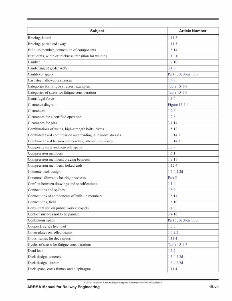
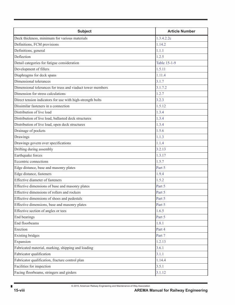
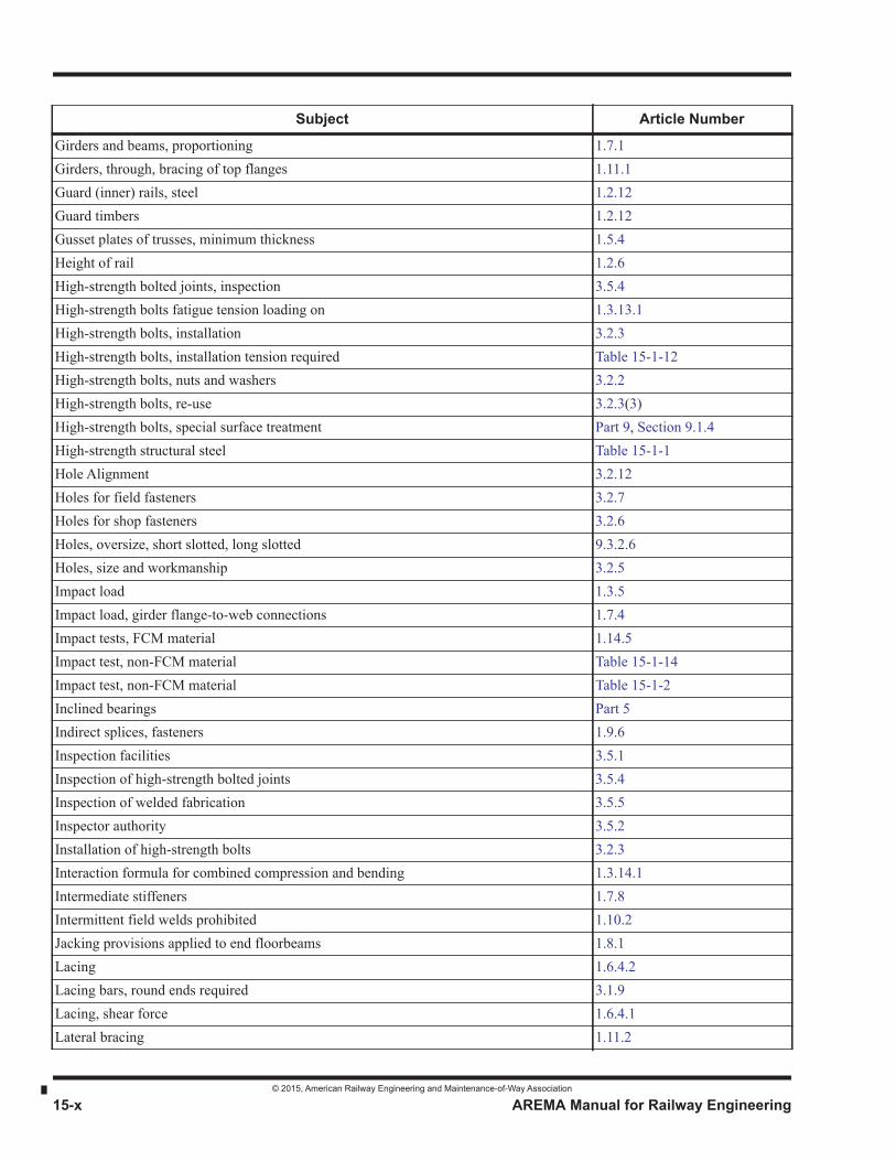
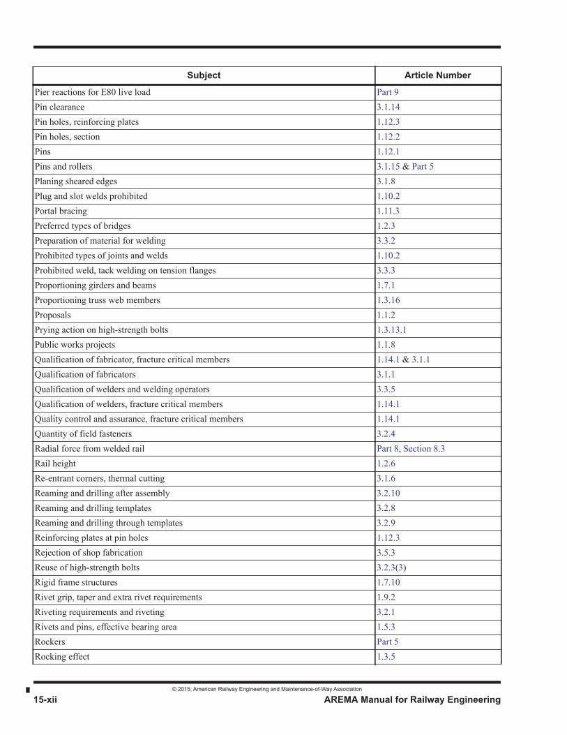
Special Index
This special index is provided for assistance in the preparation of plans and other contract papers for the construction of newbridges. It covers Part 1, Design and Part 3, Fabrication, with limited references to other chapters and parts.
Subject Article Number
Abutting joints 3.1.13Accessibility of parts 1.5.5Advance material 3.6.2Alignment of finished holes 3.2.12Allowable bearing pressure on concrete Part 5Allowable bearing pressures, masonry 1.4.4 & Part 5Allowable fatigue stress range 1.3.13Allowable load, HS bolts, special surface treatment Table 15-9-2Allowable stresses, basic Part 1, Section 1.4Allowable stresses, cast steel 1.4.3Allowable stresses, end floorbeams 1.8.1Allowable stresses, structural steel, rivets, bolts and pins 1.4.1Allowable stresses, weld metal 1.4.2Anchor bolts Part 5Angles or tees, effective section 1.6.5Angles, size of fasteners 1.9.5Assembly 3.2.10Attachments, welded 1.10.4Authority of inspector 3.5.2AWS Structural Welding Code application 1.2.2Ballasted deck structures, distribution of live load 1.3.4.2Base and cap plates, fitting 3.1.16Base plates Part 5Bearing area effective for rivets and pins 1.5.3Bearing plates and pedestals, surfaces Part 5Bearing stiffeners 1.7.7Bearings, end Part 5Bearings inclined Part 5Bent bracing 1.11.5Bolts, high-strength, installation 3.2.3Bolts, nuts and washers, high-strength 3.2.2Box members, drainage 1.5.15Bracing between compression members 1.3.11Bracing of top flange of through girders 1.11.1Bracing of viaduct towers and bents 1.11.5
© 2015, American Railway Engineering and Maintenance-of-Way Association
AREMA Manual for Railway Engineering 15-vii
1
3
4
Bracing, lateral 1.11.2Bracing, portal and sway 1.11.3Built-up member, connection of components 1.5.14Butt joints, width or thickness transition for welding 1.10.1Camber 1.2.10Cambering of girder webs 3.1.6Cantilever spans Part 1, Section 1.13Cast steel, allowable stresses 1.4.3Categories for fatigue stresses, examples Table 15-1-9Categories of stress for fatigue consideration Table 15-1-9Centrifugal force 1.3.6Clearance diagram Figure 15-1-1Clearances 1.2.6Clearances for electrified operation 1.2.6Clearances for pins 3.1.14Combinations of welds, high-strength bolts, rivets 1.5.12Combined axial compression and bending, allowable stresses 1.3.14.1Combined axial tension and bending, allowable stresses 1.3.14.2Composite steel and concrete spans 1.7.9Compression members 1.6.1Compression members, bracing between 1.3.11Compression members, forked ends 1.12.4Concrete deck design 1.3.4.2.2dConcrete, allowable bearing pressures Part 5Conflict between drawings and specifications 1.1.4Connections and splices 1.5.9Connections of components of built-up members 1.5.14Connections, field 1.5.10Consultant use on public works projects 1.1.8Contact surfaces not to be painted 3.4.1cContinuous spans Part 1, Section 1.13Cooper E series live load 1.3.3Cover plates on rolled beams 1.7.2.2Cross frames for deck spans 1.11.4Cycles of stress for fatigue considerations Table 15-1-7Dead load 1.3.2Deck design, concrete 1.3.4.2.2dDeck design, timber 1.3.4.2.2dDeck spans, cross frames and diaphragms 1.11.4
Subject Article Number
© 2015, American Railway Engineering and Maintenance-of-Way Association
15-viii AREMA Manual for Railway Engineering
Deck thickness, minimum for various materials 1.3.4.2.2cDefinitions, FCM provisions 1.14.2Definitions, general 1.1.1Deflection 1.2.5Detail categories for fatigue consideration Table 15-1-9Development of fillers 1.5.11Diaphragms for deck spans 1.11.4Dimensional tolerances 3.1.7Dimensional tolerances for truss and viaduct tower members 3.1.7.2Dimension for stress calculations 1.2.7Direct tension indicators for use with high-strength bolts 3.2.3Dissimilar fasteners in a connection 1.5.12Distribution of live load 1.3.4Distribution of live load, ballasted deck structures 1.3.4Distribution of live load, open deck structures 1.3.4Drainage of pockets 1.5.6Drawings 1.1.3Drawings govern over specifications 1.1.4Drifting during assembly 3.2.13Earthquake forces 1.3.17Eccentric connections 1.5.7Edge distance, base and masonry plates Part 5Edge distance, fasteners 1.9.4Effective diameter of fasteners 1.5.2Effective dimensions of base and masonry plates Part 5Effective dimensions of rollers and rockers Part 5Effective dimensions of shoes and pedestals Part 5Effective dimensions, base and masonry plates Part 5Effective section of angles or tees 1.6.5End bearings Part 5End floorbeams 1.8.1Erection Part 4Existing bridges Part 7Expansion 1.2.13Fabricated material, marking, shipping and loading 3.6.1Fabricator qualification 3.1.1Fabricator qualification, fracture control plan 1.14.4Facilities for inspection 3.5.1Facing floorbeams, stringers and girders 3.1.12
Subject Article Number

© 2015, American Railway Engineering and Maintenance-of-Way Association
AREMA Manual for Railway Engineering 15-ix
1
3
4
Fastener sizes in angles 1.9.5Fasteners for field use, quantity to be supplied 3.2.4Fasteners in indirect splices 1.9.6Fasteners, dissimilar types in a connection 1.5.12Fasteners, edge distance 1.9.4Fasteners, effective diameter 1.5.2Fasteners, minimum number per connection plane 1.5.9Fasteners, pitch and gage defined 1.9.1Fasteners, spacing 1.9.3Fatigue loading on high-strength bolts 1.3.13.1Fatigue, classification of members for E80 loading Table 15-1-7Fatigue, dissimilar fasteners in a connection 1.5.12Fatigue, general 1.3.13Fatigue, stress categories Table 15-1-9Fatigue, stress ranges allowed Table 15-1-10Field connections 1.5.10Field welds for live load stress prohibited 1.5.10Fillers, development 1.5.11Fillet welds 1.10.3Fit of stiffeners 3.1.10Fitting for shop riveting or bolting 3.2.13Fitting of base and cap plates 3.1.16Flange sections of girders 1.7.2Flanges splices, girders 1.7.5Flange-to-web connection, girders 1.7.4Flange-to-web welds 3.3.3Floor members, end connections 1.8.3Floorbeam reactions for E80 live load Part 9Floorbeams and Floorbeam hangers 1.8.2Floorbeams, end 1.8.1Floorbeams, end connections 1.8.3Forked ends of compression members 1.12.4Fracture control plan 1.14.1Fracture critical members or member components definitions 1.14.2Fracture critical members, design responsibilities 1.14.3Fracture critical members Part 1, Section 1.14General rules Part 1, Section 1.5Girder flanges, riveted or bolted construction 1.7.2.1Girder flanges, welded construction 1.7.2.2
Subject Article Number
© 2015, American Railway Engineering and Maintenance-of-Way Association
15-x AREMA Manual for Railway Engineering
Girders and beams, proportioning 1.7.1Girders, through, bracing of top flanges 1.11.1Guard (inner) rails, steel 1.2.12Guard timbers 1.2.12Gusset plates of trusses, minimum thickness 1.5.4Height of rail 1.2.6High-strength bolted joints, inspection 3.5.4High-strength bolts fatigue tension loading on 1.3.13.1High-strength bolts, installation 3.2.3High-strength bolts, installation tension required Table 15-1-12High-strength bolts, nuts and washers 3.2.2High-strength bolts, re-use 3.2.3(3)High-strength bolts, special surface treatment Part 9, Section 9.1.4High-strength structural steel Table 15-1-1Hole Alignment 3.2.12Holes for field fasteners 3.2.7Holes for shop fasteners 3.2.6Holes, oversize, short slotted, long slotted 9.3.2.6Holes, size and workmanship 3.2.5Impact load 1.3.5Impact load, girder flange-to-web connections 1.7.4Impact tests, FCM material 1.14.5Impact test, non-FCM material Table 15-1-14Impact test, non-FCM material Table 15-1-2Inclined bearings Part 5Indirect splices, fasteners 1.9.6Inspection facilities 3.5.1Inspection of high-strength bolted joints 3.5.4Inspection of welded fabrication 3.5.5Inspector authority 3.5.2Installation of high-strength bolts 3.2.3Interaction formula for combined compression and bending 1.3.14.1Intermediate stiffeners 1.7.8Intermittent field welds prohibited 1.10.2Jacking provisions applied to end floorbeams 1.8.1Lacing 1.6.4.2Lacing bars, round ends required 3.1.9Lacing, shear force 1.6.4.1Lateral bracing 1.11.2
Subject Article Number

© 2015, American Railway Engineering and Maintenance-of-Way Association
AREMA Manual for Railway Engineering 15-xi
1
3
4
Lateral forces from equipment 1.3.9Live load 1.3.3Live load distribution, ballasted deck structures 1.2.3Live load distribution, open deck structures 1.3.4Load, live 1.3.3Loads and forces 1.3.1Longitudinal beams or girders, design 1.3.4.2.4Longitudinal force 1.3.12Machined surfaces, shop painting 3.4.2Map for service temperature, Canada Figure 15-9-2Map for service temperatures, USA Figure 15-9-1Marking fabricated material 3.6.1Masonry plates Part 5Masonry allowable bearing pressures 1.4.4 & Part 5Match marking 3.2.11Material orders and shipping statements 3.1.2Material storage 3.1.4Material weldability 1.10.6Materials 1.2.1Moment, shear, pier reaction table, E80 Part 9Movable bridges Part 6Multiple tracks, live load 1.3.3Nameplates 1.2.11Net section 1.5.8Non-destructive testing personnel qualification, FCM work 1.14.1Notch toughness for weld metal, fracture control plan 1.14.1Notch toughness, FCM material 1.14.5 & Table 15-1-14Notch toughness, other than FCM material Table 15-1-2Notice of beginning fabrication 3.1.3Notice to Engineer 1.1.6Open deck structures, distribution of live load 1.3.4.1Oversize holes 9.3.2.6Painting of interiors of closed box members not required 1.5.15Patented devices 1.1.5Pay weight 3.6.3Pedestals Part 5Perforated cover plates 1.6.4.3Perforated cover plates, shear force 1.6.4.1Permits 1.1.7
Subject Article Number
© 2015, American Railway Engineering and Maintenance-of-Way Association
15-xii AREMA Manual for Railway Engineering
Pier reactions for E80 live load Part 9Pin clearance 3.1.14Pin holes, reinforcing plates 1.12.3Pin holes, section 1.12.2Pins 1.12.1Pins and rollers 3.1.15 & Part 5Planing sheared edges 3.1.8Plug and slot welds prohibited 1.10.2Portal bracing 1.11.3Preferred types of bridges 1.2.3Preparation of material for welding 3.3.2Prohibited types of joints and welds 1.10.2Prohibited weld, tack welding on tension flanges 3.3.3Proportioning girders and beams 1.7.1Proportioning truss web members 1.3.16Proposals 1.1.2Prying action on high-strength bolts 1.3.13.1Public works projects 1.1.8Qualification of fabricator, fracture critical members 1.14.1 & 3.1.1Qualification of fabricators 3.1.1Qualification of welders and welding operators 3.3.5Qualification of welders, fracture critical members 1.14.1Quality control and assurance, fracture critical members 1.14.1Quantity of field fasteners 3.2.4Radial force from welded rail Part 8, Section 8.3Rail height 1.2.6Re-entrant corners, thermal cutting 3.1.6Reaming and drilling after assembly 3.2.10Reaming and drilling templates 3.2.8Reaming and drilling through templates 3.2.9Reinforcing plates at pin holes 1.12.3Rejection of shop fabrication 3.5.3Reuse of high-strength bolts 3.2.3(3)Rigid frame structures 1.7.10Rivet grip, taper and extra rivet requirements 1.9.2Riveting requirements and riveting 3.2.1Rivets and pins, effective bearing area 1.5.3Rockers Part 5Rocking effect 1.3.5
Subject Article Number
© 2015, American Railway Engineering and Maintenance-of-Way Association
AREMA Manual for Railway Engineering 15-xiii
1
3
4
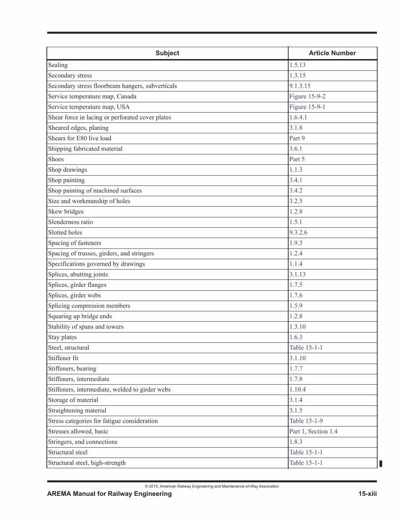
Sealing 1.5.13Secondary stress 1.3.15Secondary stress floorbeam hangers, subverticals 9.1.3.15Service temperature map, Canada Figure 15-9-2Service temperature map, USA Figure 15-9-1Shear force in lacing or perforated cover plates 1.6.4.1Sheared edges, planing 3.1.8Shears for E80 live load Part 9Shipping fabricated material 3.6.1Shoes Part 5Shop drawings 1.1.3Shop painting 3.4.1Shop painting of machined surfaces 3.4.2Size and workmanship of holes 3.2.5Skew bridges 1.2.8Slenderness ratio 1.5.1Slotted holes 9.3.2.6Spacing of fasteners 1.9.3Spacing of trusses, girders, and stringers 1.2.4Specifications governed by drawings 1.1.4Splices, abutting joints 3.1.13Splices, girder flanges 1.7.5Splices, girder webs 1.7.6Splicing compression members 1.5.9Squaring up bridge ends 1.2.8Stability of spans and towers 1.3.10Stay plates 1.6.3Steel, structural Table 15-1-1Stiffener fit 3.1.10Stiffeners, bearing 1.7.7Stiffeners, intermediate 1.7.8Stiffeners, intermediate, welded to girder webs 1.10.4Storage of material 3.1.4Straightening material 3.1.5Stress categories for fatigue consideration Table 15-1-9Stresses allowed, basic Part 1, Section 1.4Stringers, end connections 1.8.3Structural steel Table 15-1-1Structural steel, high-strength Table 15-1-1
Subject Article Number

© 2015, American Railway Engineering and Maintenance-of-Way Association
15-xiv AREMA Manual for Railway Engineering
Surfaces of bearing plates and pedestals Part 5Sway bracing 1.11.3Tack welding, prohibited on tension flanges 3.3.4Templates for reaming and drilling 3.2.8Tension required in installed high-strength bolts Table 15-1-12Thickness of compression members elements 1.6.1Thickness of girder web plates 1.7.3Thickness of metal 1.5.4Thickness outstanding elements of compression members 1.6.2Through girders, bracing of top flanges 1.11.1Ties for open deck bridges 1.2.9Timber bridge tie requirements Chapter 6Timber deck design 1.3.4.2.2dTimber guards 1.2.12Thermal cutting 3.1.6Tolerances of dimensions 3.1.7Tolerances of dimensions, truss and viaduct tower members 3.1.7.2Tolerances, sweep and camber 3.1.7.1e paragraph (2)Tower and span stability 1.3.10Transition of thickness or width in welded butt joints 1.10.1Transverse beams without stringers, diaphragm requirements 1.11.4hTransverse beams, design 1.3.4.2.3Turn-of-nut method for installing HS bolts, nut rotation Table 15-3-3Turn-of-nut method of installing high-strength bolts 3.2.3dTurntables Part 8, Section 8.1Types of bridges preferred 1.2.3Unloading pits Part 8, Section 8.4Uplift on anchor bolts Part 5Viaduct tower bracing 1.11.5Walkways and handrails on bridges Part 8, Section 8.5Web members of trusses, proportioning 1.3.16Web plate thickness, girders 1.7.3Web splices, girders 1.7.6Webs of riveted or bolted girders, control of edge position 3.1.11Weight of fabricated material for payment purposes 3.6.3Weights of material shipped 3.1.2Weld metal, allowable stresses 1.4.2Weldability of material 1.10.6Welded attachments 1.10.4
Subject Article Number
© 2015, American Railway Engineering and Maintenance-of-Way Association
AREMA Manual for Railway Engineering 15-xv
1
3
4
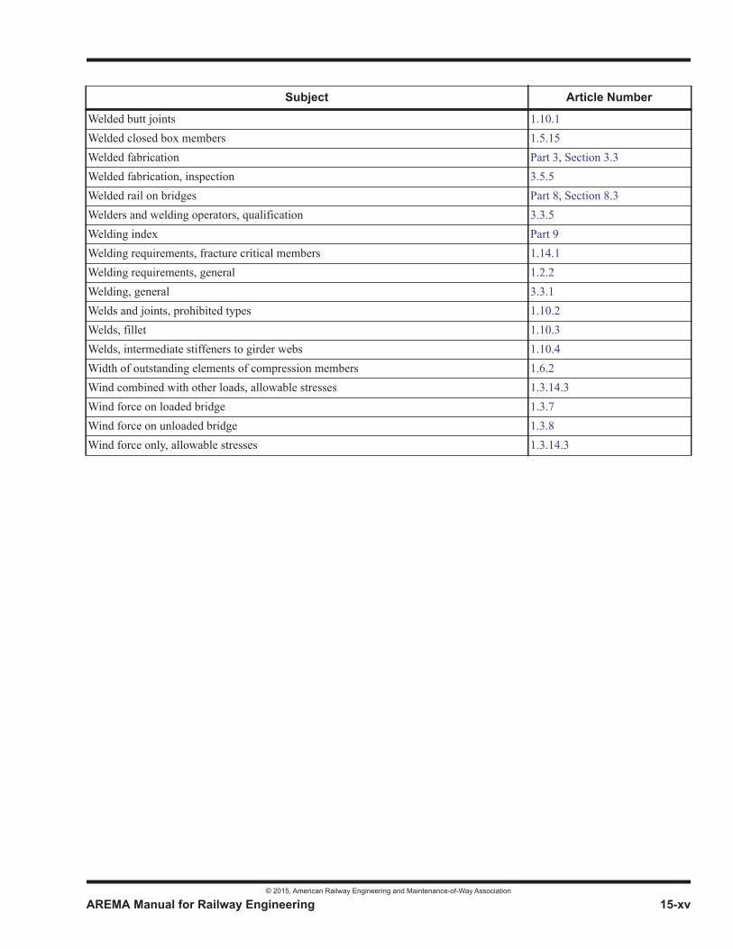
Welded butt joints 1.10.1Welded closed box members 1.5.15Welded fabrication Part 3, Section 3.3Welded fabrication, inspection 3.5.5Welded rail on bridges Part 8, Section 8.3Welders and welding operators, qualification 3.3.5Welding index Part 9Welding requirements, fracture critical members 1.14.1Welding requirements, general 1.2.2Welding, general 3.3.1Welds and joints, prohibited types 1.10.2Welds, fillet 1.10.3Welds, intermediate stiffeners to girder webs 1.10.4Width of outstanding elements of compression members 1.6.2Wind combined with other loads, allowable stresses 1.3.14.3Wind force on loaded bridge 1.3.7Wind force on unloaded bridge 1.3.8Wind force only, allowable stresses 1.3.14.3
Subject Article Number
© 2015, American Railway Engineering and Maintenance-of-Way Association
15-xvi AREMA Manual for Railway Engineering
THIS PAGE INTENTIONALLY LEFT BLANK.
© 2015, American Railway Engineering and Maintenance-of-Way Association 15-1-1
1
3
1531015Part 1
Design1
— 2015 —
FOREWORD
The purpose of this part is to formulate specific and detailed rules as a guide for the design of fixed spans using structural steel.
TABLE OF CONTENTS
Section/Article Description Page
1.1 Proposals and Drawings. . . . . . . . . . . . . . . . . . . . . . . . . . . . . . . . . . . . . . . . . . . . . . . . . . . . . . . . . . . . . . . . . . 15-1-51.1.1 Definition of Terms (1984) R(2014) . . . . . . . . . . . . . . . . . . . . . . . . . . . . . . . . . . . . . . . . . . . . . . . . . . 15-1-51.1.2 Proposals (1984) R(2014) . . . . . . . . . . . . . . . . . . . . . . . . . . . . . . . . . . . . . . . . . . . . . . . . . . . . . . . . . . 15-1-51.1.3 Shop Drawings (2015) . . . . . . . . . . . . . . . . . . . . . . . . . . . . . . . . . . . . . . . . . . . . . . . . . . . . . . . . . . . . . 15-1-51.1.4 Drawings to Govern (1993) R(2014) . . . . . . . . . . . . . . . . . . . . . . . . . . . . . . . . . . . . . . . . . . . . . . . . . . 15-1-61.1.5 Patented Technologies (1993) R(2014) . . . . . . . . . . . . . . . . . . . . . . . . . . . . . . . . . . . . . . . . . . . . . . . . 15-1-61.1.6 Notice to Engineer (1993) R(2014) . . . . . . . . . . . . . . . . . . . . . . . . . . . . . . . . . . . . . . . . . . . . . . . . . . . 15-1-61.1.7 Permits (1993) R(2014) . . . . . . . . . . . . . . . . . . . . . . . . . . . . . . . . . . . . . . . . . . . . . . . . . . . . . . . . . . . . 15-1-61.1.8 Design of Public Works Projects (1993) R(2014) . . . . . . . . . . . . . . . . . . . . . . . . . . . . . . . . . . . . . . . . 15-1-6
1.2 General Requirements . . . . . . . . . . . . . . . . . . . . . . . . . . . . . . . . . . . . . . . . . . . . . . . . . . . . . . . . . . . . . . . . . . . 15-1-71.2.1 Materials (2014) . . . . . . . . . . . . . . . . . . . . . . . . . . . . . . . . . . . . . . . . . . . . . . . . . . . . . . . . . . . . . . . . . . 15-1-71.2.2 Welding (2003) R(2014) . . . . . . . . . . . . . . . . . . . . . . . . . . . . . . . . . . . . . . . . . . . . . . . . . . . . . . . . . . . 15-1-101.2.3 Types of Bridges (1995) R(2014) . . . . . . . . . . . . . . . . . . . . . . . . . . . . . . . . . . . . . . . . . . . . . . . . . . . . 15-1-11
1 References, Vol. 4, 1903, pp. 130, 141, 253; Vol. 5, 1904, p. 581; Vol. 6, 1905, pp. 218, 447; Vol. 7, 1906, pp. 185, 235; Vol. 11, 1910, part 1, pp. 115, 160; Vol. 21, 1920, pp. 493, 1398; Vol. 25, 1924, pp. 1072, 1262; Vol. 35, 1934, pp. 1021, 1196; Vol. 36, 1935, pp. 633, 987; Vol. 39, 1938, pp. 153, 891; Vol. 41, 1940, pp. 408, 858; Vol. 42, 1941, pp. 356, 874; Vol. 43, 1942, pp. 365, 737; Vol. 44, 1943, pp. 400, 670, 685; Vol. 45, 1944, pp. 180, 605; Vol. 47, 1946, pp. 245, 647; Vol. 48, 1947, pp. 391, 930; Vol. 49, 1948, pp. 199, 666; Vol. 50, 1949, pp. 425, 749; Vol. 51, 1950, pp. 443, 904; Vol. 53, 1952, pp. 508, 1061; Vol. 54, 1953, pp. 905, 1346; Vol. 55, 1954, pp. 586, 1020; Vol. 56, 1955, pp. 590, 1085; Vol. 57, 1956, pp. 554, 998; Vol. 58, 1957, pp. 685, 1191; Vol. 59, 1958, pp. 700, 702, 1194, 1195; Vol. 60, 1959, pp. 506, 508, 1098, 1100; Vol. 61, 1960, pp. 560, 1127; Vol. 62, 1961, pp. 545, 550, 551, 876, 877; Vol. 63, 1962, pp. 382, 699; Vol. 64, 1963, pp. 361, 630; Vol. 65, 1964, pp. 382, 775; Vol. 66, 1965, pp. 292, 653; Vol. 67, 1966, pp. 341, 697; Vol. 68, 1967, p. 350; Vol. 70, 1969, p. 241; Vol. 71, 1970, p. 375; Vol. 72, 1971, p. 153; Vol. 73, 1972, p. 176; Vol. 74, 1973, p. 137; Vol. 75, 1974, p. 334; Vol. 76, 1975, p. 240; Vol. 77, 1976, p. 249; Vol. 78, 1977, p. 77; Vol. 79, 1978, p. 45; Vol. 80, 1979, p. 188; Vol. 82, 1981, p. 78; Vol. 83, 1982, p. 372; Vol. 84, 1983, p. 100; Vol. 86, 1985, p. 90; Vol. 87, 1986, p. 103; Vol. 88, 1987, p. 87; Vol. 90, 1989, p. 98; Vol. 91, 1990, p. 121; Vol. 92, 1991, 67; Vol. 94, 1994, p. 131; Vol. 96, p. 66; Vol. 97, p. 171. Reapproved with revisions 1996.
Steel Structures
© 2015, American Railway Engineering and Maintenance-of-Way Association
15-1-2 AREMA Manual for Railway Engineering
TABLE OF CONTENTS (CONT)
Section/Article Description Page
1.2.4 Spacing of Trusses, Girders, and Stringers (1995) R(2014) . . . . . . . . . . . . . . . . . . . . . . . . . . . . . . . 15-1-111.2.5 Deflection (2013) R(2014) . . . . . . . . . . . . . . . . . . . . . . . . . . . . . . . . . . . . . . . . . . . . . . . . . . . . . . . . . 15-1-111.2.6 Clearances (1995) R(2014). . . . . . . . . . . . . . . . . . . . . . . . . . . . . . . . . . . . . . . . . . . . . . . . . . . . . . . . . 15-1-121.2.7 Dimensions for Calculations of Stresses (2004) R(2014) . . . . . . . . . . . . . . . . . . . . . . . . . . . . . . . . . 15-1-131.2.8 Skew Bridges (1994) R(2014) . . . . . . . . . . . . . . . . . . . . . . . . . . . . . . . . . . . . . . . . . . . . . . . . . . . . . . 15-1-141.2.9 Open Deck Bridge Ties (1994) R(2014) . . . . . . . . . . . . . . . . . . . . . . . . . . . . . . . . . . . . . . . . . . . . . . 15-1-141.2.10 Camber (1995) R(2014) . . . . . . . . . . . . . . . . . . . . . . . . . . . . . . . . . . . . . . . . . . . . . . . . . . . . . . . . . . . 15-1-141.2.11 Nameplates (1995) R(2014) . . . . . . . . . . . . . . . . . . . . . . . . . . . . . . . . . . . . . . . . . . . . . . . . . . . . . . . . 15-1-141.2.12 Steel Inner Guard Rails and Guard Timbers (1995) R(2014) . . . . . . . . . . . . . . . . . . . . . . . . . . . . . . 15-1-141.2.13 Provision for Expansion (2008) R(2014) . . . . . . . . . . . . . . . . . . . . . . . . . . . . . . . . . . . . . . . . . . . . . . 15-1-141.2.14 Special Trackwork on Bridges (2015) . . . . . . . . . . . . . . . . . . . . . . . . . . . . . . . . . . . . . . . . . . . . . . . . 15-1-14
1.3 Loads, Forces and Stresses. . . . . . . . . . . . . . . . . . . . . . . . . . . . . . . . . . . . . . . . . . . . . . . . . . . . . . . . . . . . . . . 15-1-141.3.1 Loads and Forces (1995) R(2014) . . . . . . . . . . . . . . . . . . . . . . . . . . . . . . . . . . . . . . . . . . . . . . . . . . . 15-1-141.3.2 Dead Load (1995) R(2014) . . . . . . . . . . . . . . . . . . . . . . . . . . . . . . . . . . . . . . . . . . . . . . . . . . . . . . . . 15-1-151.3.3 Live Load (1995) R(2014) . . . . . . . . . . . . . . . . . . . . . . . . . . . . . . . . . . . . . . . . . . . . . . . . . . . . . . . . . 15-1-151.3.4 Distribution of Live Load (1993) R(2014). . . . . . . . . . . . . . . . . . . . . . . . . . . . . . . . . . . . . . . . . . . . . 15-1-171.3.5 Impact Load (2007) R(2014) . . . . . . . . . . . . . . . . . . . . . . . . . . . . . . . . . . . . . . . . . . . . . . . . . . . . . . . 15-1-191.3.6 Centrifugal Force (2002) R(2014) . . . . . . . . . . . . . . . . . . . . . . . . . . . . . . . . . . . . . . . . . . . . . . . . . . . 15-1-201.3.7 Wind Forces on Loaded Bridge (2003) R(2014) . . . . . . . . . . . . . . . . . . . . . . . . . . . . . . . . . . . . . . . . 15-1-211.3.8 Wind Forces on Unloaded Bridge (2006) R(2014) . . . . . . . . . . . . . . . . . . . . . . . . . . . . . . . . . . . . . . 15-1-211.3.9 Lateral Forces from Equipment (1993) R(2014) . . . . . . . . . . . . . . . . . . . . . . . . . . . . . . . . . . . . . . . . 15-1-221.3.10 Stability Check (2005) R(2014) . . . . . . . . . . . . . . . . . . . . . . . . . . . . . . . . . . . . . . . . . . . . . . . . . . . . . 15-1-221.3.11 Bracing Between Compression Members (2000) R(2014) . . . . . . . . . . . . . . . . . . . . . . . . . . . . . . . . 15-1-231.3.12 Longitudinal Forces (2005) R(2014) . . . . . . . . . . . . . . . . . . . . . . . . . . . . . . . . . . . . . . . . . . . . . . . . . 15-1-231.3.13 Fatigue (2015) . . . . . . . . . . . . . . . . . . . . . . . . . . . . . . . . . . . . . . . . . . . . . . . . . . . . . . . . . . . . . . . . . . 15-1-231.3.14 Combined Stresses (2005) R(2014) . . . . . . . . . . . . . . . . . . . . . . . . . . . . . . . . . . . . . . . . . . . . . . . . . . 15-1-381.3.15 Secondary Stresses (1994) R(2014) . . . . . . . . . . . . . . . . . . . . . . . . . . . . . . . . . . . . . . . . . . . . . . . . . . 15-1-391.3.16 Proportioning of Truss Web Members (2004) R(2014) . . . . . . . . . . . . . . . . . . . . . . . . . . . . . . . . . . . 15-1-391.3.17 Earthquake Forces (1994) R(2014) . . . . . . . . . . . . . . . . . . . . . . . . . . . . . . . . . . . . . . . . . . . . . . . . . . 15-1-40
1.4 Basic Allowable Stresses . . . . . . . . . . . . . . . . . . . . . . . . . . . . . . . . . . . . . . . . . . . . . . . . . . . . . . . . . . . . . . . . . 15-1-401.4.1 Structural Steel, Rivets, Bolts and Pins (2011) R(2014) . . . . . . . . . . . . . . . . . . . . . . . . . . . . . . . . . . 15-1-401.4.2 Weld Metal (1994) R(2008) . . . . . . . . . . . . . . . . . . . . . . . . . . . . . . . . . . . . . . . . . . . . . . . . . . . . . . . . 15-1-441.4.3 Cast Steel (1994) R(2014) . . . . . . . . . . . . . . . . . . . . . . . . . . . . . . . . . . . . . . . . . . . . . . . . . . . . . . . . . 15-1-451.4.4 Masonry (2002) R(2014) . . . . . . . . . . . . . . . . . . . . . . . . . . . . . . . . . . . . . . . . . . . . . . . . . . . . . . . . . . 15-1-451.4.5 Timber Bridge Ties (1994) R(2014) . . . . . . . . . . . . . . . . . . . . . . . . . . . . . . . . . . . . . . . . . . . . . . . . . 15-1-45
1.5 General Rules . . . . . . . . . . . . . . . . . . . . . . . . . . . . . . . . . . . . . . . . . . . . . . . . . . . . . . . . . . . . . . . . . . . . . . . . . 15-1-451.5.1 Slenderness Ratio (2011) R(2014) . . . . . . . . . . . . . . . . . . . . . . . . . . . . . . . . . . . . . . . . . . . . . . . . . . . 15-1-451.5.2 Effective Diameter of Fasteners (1993) R(2014) . . . . . . . . . . . . . . . . . . . . . . . . . . . . . . . . . . . . . . . . 15-1-461.5.3 Effective Bearing Area of Bolts, Rivets and Pins (1993) R(2014). . . . . . . . . . . . . . . . . . . . . . . . . . . 15-1-461.5.4 Thickness of Material (2011) R(2014) . . . . . . . . . . . . . . . . . . . . . . . . . . . . . . . . . . . . . . . . . . . . . . . . 15-1-461.5.5 Accessibility of Parts (1993) R(2014) . . . . . . . . . . . . . . . . . . . . . . . . . . . . . . . . . . . . . . . . . . . . . . . . 15-1-461.5.6 Drainage of Pockets (1993) R(2014) . . . . . . . . . . . . . . . . . . . . . . . . . . . . . . . . . . . . . . . . . . . . . . . . . 15-1-461.5.7 Eccentric Connections (1993) R(2014) . . . . . . . . . . . . . . . . . . . . . . . . . . . . . . . . . . . . . . . . . . . . . . . 15-1-461.5.8 Net Section (2005) R(2014) . . . . . . . . . . . . . . . . . . . . . . . . . . . . . . . . . . . . . . . . . . . . . . . . . . . . . . . . 15-1-471.5.9 Connections and Splices (2014) . . . . . . . . . . . . . . . . . . . . . . . . . . . . . . . . . . . . . . . . . . . . . . . . . . . . . 15-1-471.5.10 Field Connections (1994) R(2014). . . . . . . . . . . . . . . . . . . . . . . . . . . . . . . . . . . . . . . . . . . . . . . . . . . 15-1-48
Design
© 2015, American Railway Engineering and Maintenance-of-Way Association
AREMA Manual for Railway Engineering 15-1-3
1
3
4
TABLE OF CONTENTS (CONT)
Section/Article Description Page
1.5.11 Development of Fillers (2015) . . . . . . . . . . . . . . . . . . . . . . . . . . . . . . . . . . . . . . . . . . . . . . . . . . . . . . . 15-1-481.5.12 Combinations of Dissimilar Types of Connections (1993) R(2014) . . . . . . . . . . . . . . . . . . . . . . . . . . 15-1-491.5.13 Sealing (1993) R(2014) . . . . . . . . . . . . . . . . . . . . . . . . . . . . . . . . . . . . . . . . . . . . . . . . . . . . . . . . . . . . 15-1-491.5.14 Connections of Components of Built-up Members (1993) R(2014) . . . . . . . . . . . . . . . . . . . . . . . . . . 15-1-491.5.15 Welded Closed Box Members (1993) R(2014) . . . . . . . . . . . . . . . . . . . . . . . . . . . . . . . . . . . . . . . . . . 15-1-49
1.6 Members Stressed Primarily in Axial Tension or Compression . . . . . . . . . . . . . . . . . . . . . . . . . . . . . . . . . 15-1-501.6.1 Compression Members (2004) R(2014) . . . . . . . . . . . . . . . . . . . . . . . . . . . . . . . . . . . . . . . . . . . . . . . 15-1-501.6.2 Outstanding Elements in Compression (2004) R(2014) . . . . . . . . . . . . . . . . . . . . . . . . . . . . . . . . . . . 15-1-501.6.3 Stay Plates (1994) R(2014) . . . . . . . . . . . . . . . . . . . . . . . . . . . . . . . . . . . . . . . . . . . . . . . . . . . . . . . . . 15-1-511.6.4 Lacing and Perforated Cover Plates for Tension and Compression Members (2009) R(2014) . . . . . 15-1-521.6.5 Effective Net Area for Tension Members - Strength (2008) R(2014) . . . . . . . . . . . . . . . . . . . . . . . . . 15-1-531.6.6 Effective Area for Tension Members - Fatigue (2007) R(2014) . . . . . . . . . . . . . . . . . . . . . . . . . . . . . 15-1-55
1.7 Members Stressed Primarily in Bending . . . . . . . . . . . . . . . . . . . . . . . . . . . . . . . . . . . . . . . . . . . . . . . . . . . . 15-1-551.7.1 Proportioning Girders and Beams (2004) R(2014) . . . . . . . . . . . . . . . . . . . . . . . . . . . . . . . . . . . . . . . 15-1-551.7.2 Flange Sections (1994) R(2014) . . . . . . . . . . . . . . . . . . . . . . . . . . . . . . . . . . . . . . . . . . . . . . . . . . . . . 15-1-561.7.3 Thickness of Web Plates (2004) R(2014) . . . . . . . . . . . . . . . . . . . . . . . . . . . . . . . . . . . . . . . . . . . . . . 15-1-561.7.4 Flange-to-Web Connection of Plate Girders (2009) R(2014) . . . . . . . . . . . . . . . . . . . . . . . . . . . . . . . 15-1-571.7.5 Flange Splices (2014). . . . . . . . . . . . . . . . . . . . . . . . . . . . . . . . . . . . . . . . . . . . . . . . . . . . . . . . . . . . . . 15-1-571.7.6 Web Splices (1994) R(2014) . . . . . . . . . . . . . . . . . . . . . . . . . . . . . . . . . . . . . . . . . . . . . . . . . . . . . . . . 15-1-581.7.7 Stiffeners at Points of Bearing (2012) R(2014) . . . . . . . . . . . . . . . . . . . . . . . . . . . . . . . . . . . . . . . . . . 15-1-581.7.8 Web Plate Stiffeners (Intermediate Transverse and Longitudinal) (2012) R(2014) . . . . . . . . . . . . . . 15-1-581.7.9 Composite Steel and Concrete Spans (2008) R(2014). . . . . . . . . . . . . . . . . . . . . . . . . . . . . . . . . . . . . 15-1-601.7.10 Rigid Frame Structures (2008) R(2014) . . . . . . . . . . . . . . . . . . . . . . . . . . . . . . . . . . . . . . . . . . . . . . . 15-1-64
1.8 Floor Members and Floorbeam Hangers . . . . . . . . . . . . . . . . . . . . . . . . . . . . . . . . . . . . . . . . . . . . . . . . . . . . 15-1-661.8.1 End Floorbeams (1993) R(2014) . . . . . . . . . . . . . . . . . . . . . . . . . . . . . . . . . . . . . . . . . . . . . . . . . . . . . 15-1-661.8.2 Floorbeams and Floorbeam Hangers (1993) R(2014) . . . . . . . . . . . . . . . . . . . . . . . . . . . . . . . . . . . . . 15-1-661.8.3 End Connections of Floor Members (1993) R(2014) . . . . . . . . . . . . . . . . . . . . . . . . . . . . . . . . . . . . . 15-1-66
1.9 Riveted and Bolted Construction . . . . . . . . . . . . . . . . . . . . . . . . . . . . . . . . . . . . . . . . . . . . . . . . . . . . . . . . . . 15-1-671.9.1 Pitch and Gage of Fasteners (1993) R(2014). . . . . . . . . . . . . . . . . . . . . . . . . . . . . . . . . . . . . . . . . . . . 15-1-671.9.2 Grip of Rivets (1993) R(2014). . . . . . . . . . . . . . . . . . . . . . . . . . . . . . . . . . . . . . . . . . . . . . . . . . . . . . . 15-1-671.9.3 Minimum Spacing of Fasteners (1993) R(2014) . . . . . . . . . . . . . . . . . . . . . . . . . . . . . . . . . . . . . . . . . 15-1-671.9.4 Edge Distance of Fasteners (2005) R(2014) . . . . . . . . . . . . . . . . . . . . . . . . . . . . . . . . . . . . . . . . . . . . 15-1-671.9.5 Sizes of Fasteners in Angles (1993) R(2014). . . . . . . . . . . . . . . . . . . . . . . . . . . . . . . . . . . . . . . . . . . . 15-1-681.9.6 Fasteners in Indirect Splices (2015). . . . . . . . . . . . . . . . . . . . . . . . . . . . . . . . . . . . . . . . . . . . . . . . . . . 15-1-68
1.10 Welded Construction . . . . . . . . . . . . . . . . . . . . . . . . . . . . . . . . . . . . . . . . . . . . . . . . . . . . . . . . . . . . . . . . . . . . 15-1-681.10.1 Transition of Thickness or Widths in Welded Butt Joints (2012) R(2014) . . . . . . . . . . . . . . . . . . . . . 15-1-681.10.2 Prohibited Types of Joints and Welds (2008) R(2014) . . . . . . . . . . . . . . . . . . . . . . . . . . . . . . . . . . . . 15-1-691.10.3 Fillet Welds (1993) R(2014) . . . . . . . . . . . . . . . . . . . . . . . . . . . . . . . . . . . . . . . . . . . . . . . . . . . . . . . . 15-1-691.10.4 Welded Attachments (2004) R(2014). . . . . . . . . . . . . . . . . . . . . . . . . . . . . . . . . . . . . . . . . . . . . . . . . . 15-1-691.10.5 Fracture Critical Members (1994) R(2014) . . . . . . . . . . . . . . . . . . . . . . . . . . . . . . . . . . . . . . . . . . . . . 15-1-701.10.6 Material Weldability (2006) R(2014). . . . . . . . . . . . . . . . . . . . . . . . . . . . . . . . . . . . . . . . . . . . . . . . . . 15-1-70
1.11 Bracing. . . . . . . . . . . . . . . . . . . . . . . . . . . . . . . . . . . . . . . . . . . . . . . . . . . . . . . . . . . . . . . . . . . . . . . . . . . . . . . . 15-1-701.11.1 Bracing of Top Flanges of Through Girders (2000) R(2014) . . . . . . . . . . . . . . . . . . . . . . . . . . . . . . . 15-1-70
Steel Structures
© 2015, American Railway Engineering and Maintenance-of-Way Association
15-1-4 AREMA Manual for Railway Engineering
TABLE OF CONTENTS (CONT)
Section/Article Description Page
1.11.2 Lateral Bracing (2012) R(2014) . . . . . . . . . . . . . . . . . . . . . . . . . . . . . . . . . . . . . . . . . . . . . . . . . . . . . 15-1-701.11.3 Portal and Sway Bracing (1994) R(2014) . . . . . . . . . . . . . . . . . . . . . . . . . . . . . . . . . . . . . . . . . . . . . 15-1-711.11.4 Cross Frames and Diaphragms for Deck Spans (1994) R(2014) . . . . . . . . . . . . . . . . . . . . . . . . . . . . 15-1-711.11.5 Bracing of Viaduct Towers and Bents (1994) R(2014) . . . . . . . . . . . . . . . . . . . . . . . . . . . . . . . . . . . 15-1-711.11.6 Bracing Members Used as Ties or Struts Only (1994) R(2014) . . . . . . . . . . . . . . . . . . . . . . . . . . . . 15-1-72
1.12 Pins and Pin-Connected Members . . . . . . . . . . . . . . . . . . . . . . . . . . . . . . . . . . . . . . . . . . . . . . . . . . . . . . . . 15-1-721.12.1 Pins (2014) . . . . . . . . . . . . . . . . . . . . . . . . . . . . . . . . . . . . . . . . . . . . . . . . . . . . . . . . . . . . . . . . . . . . . 15-1-721.12.2 Section at Pin Holes (1993) R(2014) . . . . . . . . . . . . . . . . . . . . . . . . . . . . . . . . . . . . . . . . . . . . . . . . . 15-1-721.12.3 Reinforcing Plates at Pin Holes (1993) R(2014) . . . . . . . . . . . . . . . . . . . . . . . . . . . . . . . . . . . . . . . . 15-1-721.12.4 Forked Ends of Compression Members (1993) R(2014) . . . . . . . . . . . . . . . . . . . . . . . . . . . . . . . . . . 15-1-72
1.13 Continuous and Cantilever Steel Structures . . . . . . . . . . . . . . . . . . . . . . . . . . . . . . . . . . . . . . . . . . . . . . . . 15-1-731.13.1 Definition (2008) R(2014) . . . . . . . . . . . . . . . . . . . . . . . . . . . . . . . . . . . . . . . . . . . . . . . . . . . . . . . . . 15-1-731.13.2 Basic Design Assumptions (2008) R(2014) . . . . . . . . . . . . . . . . . . . . . . . . . . . . . . . . . . . . . . . . . . . . 15-1-731.13.3 Deflection (2008) R(2014) . . . . . . . . . . . . . . . . . . . . . . . . . . . . . . . . . . . . . . . . . . . . . . . . . . . . . . . . . 15-1-731.13.4 Camber (2008) R(2014) . . . . . . . . . . . . . . . . . . . . . . . . . . . . . . . . . . . . . . . . . . . . . . . . . . . . . . . . . . . 15-1-731.13.5 Impact Load (2008) R(2014) . . . . . . . . . . . . . . . . . . . . . . . . . . . . . . . . . . . . . . . . . . . . . . . . . . . . . . . 15-1-741.13.6 Uplift (2015). . . . . . . . . . . . . . . . . . . . . . . . . . . . . . . . . . . . . . . . . . . . . . . . . . . . . . . . . . . . . . . . . . . . 15-1-741.13.7 Bracing (2008) R(2014) . . . . . . . . . . . . . . . . . . . . . . . . . . . . . . . . . . . . . . . . . . . . . . . . . . . . . . . . . . . 15-1-741.13.8 Longitudinal Stiffeners (2010) . . . . . . . . . . . . . . . . . . . . . . . . . . . . . . . . . . . . . . . . . . . . . . . . . . . . . . 15-1-741.13.9 Cover Plates (2008) R(2014) . . . . . . . . . . . . . . . . . . . . . . . . . . . . . . . . . . . . . . . . . . . . . . . . . . . . . . . 15-1-751.13.10 Splices in Flexural Members (2008) R(2014) . . . . . . . . . . . . . . . . . . . . . . . . . . . . . . . . . . . . . . . . . . 15-1-75
1.14 Fracture Critical Members . . . . . . . . . . . . . . . . . . . . . . . . . . . . . . . . . . . . . . . . . . . . . . . . . . . . . . . . . . . . . . 15-1-761.14.1 Scope (2001) R(2013) . . . . . . . . . . . . . . . . . . . . . . . . . . . . . . . . . . . . . . . . . . . . . . . . . . . . . . . . . . . . 15-1-761.14.2 Definitions (2013) . . . . . . . . . . . . . . . . . . . . . . . . . . . . . . . . . . . . . . . . . . . . . . . . . . . . . . . . . . . . . . . 15-1-761.14.3 Design and Review Responsibilities (1997) R(2008) . . . . . . . . . . . . . . . . . . . . . . . . . . . . . . . . . . . . 15-1-761.14.4 Special Welding Requirements (1997) R(2008). . . . . . . . . . . . . . . . . . . . . . . . . . . . . . . . . . . . . . . . . 15-1-761.14.5 Notch Toughness of Steel in Fracture Critical Members (2010) . . . . . . . . . . . . . . . . . . . . . . . . . . . . 15-1-76
1.15 Live Load Moments, Shears and Reactions . . . . . . . . . . . . . . . . . . . . . . . . . . . . . . . . . . . . . . . . . . . . . . . . . 15-1-781.15.1 Tabulated Values for Simple Spans (2003) R(2014) . . . . . . . . . . . . . . . . . . . . . . . . . . . . . . . . . . . . . 15-1-781.15.2 Supplemental Formulas for Simple Spans (2009) R(2014) . . . . . . . . . . . . . . . . . . . . . . . . . . . . . . . . 15-1-79
LIST OF FIGURES
Figure Description Page
15-1-1 Minimum Railway Bridge Clearances . . . . . . . . . . . . . . . . . . . . . . . . . . . . . . . . . . . . . . . . . . . . . . . . . . . . . 15-1-1315-1-2 Cooper E 80 Load . . . . . . . . . . . . . . . . . . . . . . . . . . . . . . . . . . . . . . . . . . . . . . . . . . . . . . . . . . . . . . . . . . . . 15-1-1615-1-3 Alternate Live Load on 4 Axles . . . . . . . . . . . . . . . . . . . . . . . . . . . . . . . . . . . . . . . . . . . . . . . . . . . . . . . . . . 15-1-1615-1-4 Location of Eccentric Load . . . . . . . . . . . . . . . . . . . . . . . . . . . . . . . . . . . . . . . . . . . . . . . . . . . . . . . . . . . . . 15-1-2215-1-5 Determination of x . . . . . . . . . . . . . . . . . . . . . . . . . . . . . . . . . . . . . . . . . . . . . . . . . . . . . . . . . . . . . . . . . . . . 15-1-54
Design
© 2015, American Railway Engineering and Maintenance-of-Way Association
AREMA Manual for Railway Engineering 15-1-5
1
3
4
LIST OF TABLES
Table Description Page
15-1-1 Structural Steel. . . . . . . . . . . . . . . . . . . . . . . . . . . . . . . . . . . . . . . . . . . . . . . . . . . . . . . . . . . . . . . . . . . . . . . . 15-1-815-1-2 Impact Test Requirements for Structural Steel – Other than Fracture Critical Members . . . . . . . . . . . . . . . 15-1-915-1-3 Equivalent Materials . . . . . . . . . . . . . . . . . . . . . . . . . . . . . . . . . . . . . . . . . . . . . . . . . . . . . . . . . . . . . . . . . . . 15-1-1015-1-4 Curved Track Clearance Increases. . . . . . . . . . . . . . . . . . . . . . . . . . . . . . . . . . . . . . . . . . . . . . . . . . . . . . . . . 15-1-1315-1-5 Unit Weights for Dead Load Stresses . . . . . . . . . . . . . . . . . . . . . . . . . . . . . . . . . . . . . . . . . . . . . . . . . . . . . . 15-1-1515-1-6 Impact Loads . . . . . . . . . . . . . . . . . . . . . . . . . . . . . . . . . . . . . . . . . . . . . . . . . . . . . . . . . . . . . . . . . . . . . . . . . 15-1-2015-1-7 Number of Stress Cycles, N. . . . . . . . . . . . . . . . . . . . . . . . . . . . . . . . . . . . . . . . . . . . . . . . . . . . . . . . . . . . . . 15-1-2515-1-8 Assumed Mean Impact Load Percentages . . . . . . . . . . . . . . . . . . . . . . . . . . . . . . . . . . . . . . . . . . . . . . . . . . . 15-1-2515-1-9 Detail Categories for Load Induced Fatigue . . . . . . . . . . . . . . . . . . . . . . . . . . . . . . . . . . . . . . . . . . . . . . . . . 15-1-2715-1-10 Allowable Fatigue Stress Range, SRfat (ksi) . . . . . . . . . . . . . . . . . . . . . . . . . . . . . . . . . . . . . . . . . . . . . . . . . 15-1-3715-1-11 Structural Steel, Rivets, Bolts and Pins . . . . . . . . . . . . . . . . . . . . . . . . . . . . . . . . . . . . . . . . . . . . . . . . . . . . . 15-1-4115-1-11a Allowable Stress for Slip-Critical Connections (Slip Load per Unit of Bolt Area, psi). . . . . . . . . . . . . . . . 15-1-4415-1-12 Minimum Tension of Installed Bolts . . . . . . . . . . . . . . . . . . . . . . . . . . . . . . . . . . . . . . . . . . . . . . . . . . . . . . . 15-1-4415-1-13 Allowable Stress on Welds . . . . . . . . . . . . . . . . . . . . . . . . . . . . . . . . . . . . . . . . . . . . . . . . . . . . . . . . . . . . . . 15-1-4515-1-14 Impact Test Requirements for Structural Steel - Fracture Critical Members . . . . . . . . . . . . . . . . . . . . . . . . 15-1-7715-1-15 Maximum Moments, Shears and Pier (or Floorbeam) Reactions for Cooper E 80 Live Load or Alternate Live Load . . . . . . . . . . . . . . . . . . . . . . . . . . . . . . . . . . . . . . . . . . . . . . . . . . . . . . . . . . . . . . . . . . . . . . . . . . . . . . . . . . . . 15-1-7815-1-16 Calculation of Maximum Moments on Short, Simple Spans . . . . . . . . . . . . . . . . . . . . . . . . . . . . . . . . . . . . 15-1-79
SECTION 1.1 PROPOSALS AND DRAWINGS
1.1.1 DEFINITION OF TERMS (1984) R(2014)
The term “Company” means the railway company party to the contract. The term “Engineer” means the chief engineering officer of the Company or this individual’s authorized representative. The term “Inspector” means the inspector representing the Company. The term “Contractor” means the manufacturing, fabricating or erecting contractor party to the contract.
1.1.2 PROPOSALS (1984) R(2014)
a. Bidders shall submit proposals conforming to the terms in the letter of invitation. The proposals shall be based on plans and specifications furnished by the Company. Such plans and specifications shall show the conditions determining the design of the bridge, the general dimensions, force and stress data and typical details.
b. When the invitation requires the Contractor to furnish the design, the invitation shall state the design criteria and the general conditions at the site, such as the track spacing, foundation soil conditions, presence of old structures and traffic conditions.
1.1.3 SHOP DRAWINGS (2015)
a. After the contract has been awarded, the Contractor shall submit to the Engineer, for review and approval as to conformity to contract requirements, prints from checked plans in the number required, of stress sheets, shop drawings and erection procedures, unless such sheets, drawings and procedures have been prepared by the Company.
b. The original drawings shall be legible. They shall be delivered to and become the property of the Company upon completion of the contract.
Steel Structures
© 2015, American Railway Engineering and Maintenance-of-Way Association
15-1-6 AREMA Manual for Railway Engineering
c. Alternately, electronic drawings or other models may be submitted in an approved format and via a method approved by the Engineer.
d. Shop drawing size shall be preferably 24 inches by 36 inches, including left margin 1-1/2 inches wide and 1/2 inch margin on other edges. An approved title shall be in the lower right corner.
e. Where any changes or corrections are required by the Engineer, one print, with changes shown thereon, shall be returned to the Contractor either electronically or by conventional method. Prints from corrected plans shall be submitted to the Engineer for review, and this procedure shall continue until each drawing, etc., is approved.
f. No additional change shall be made to such approved drawings without the consent of the Engineer.
g. The Contractor shall furnish to the Company as many prints of the drawings as required to carry out the work.
h. The Contractor shall be wholly responsible for the accuracy and completeness of the drawings, regardless of the approval by the Engineer.
i. Any work performed or material ordered prior to shop drawing (or, if acceptable to the Engineer and Owner, other model) approval by the Engineer shall be at the sole risk of the Contractor.
1.1.4 DRAWINGS TO GOVERN (1993) R(2014)
Where the drawings and the specifications conflict, the drawings shall govern.
1.1.5 PATENTED TECHNOLOGIES (1993) R(2014)
The Contractor shall protect the Company against claims arising from the use of patented technologies or parts proposed by the Contractor.
1.1.6 NOTICE TO ENGINEER (1993) R(2014)
No material shall be rolled or any work performed before the Engineer has been notified in writing where the orders have been placed.
1.1.7 PERMITS (1993) R(2014)
All permits required for the location and construction of the structure shall be obtained as directed by the Company.
1.1.8 DESIGN OF PUBLIC WORKS PROJECTS (1993)1 R(2014)
a. The design, plans, special provisions and specifications for railroad bridges to be built as a public works project and paid for with public funds administered by a public agency shall be prepared by the engineering staff of the Company involved or by a consulting engineer or the staff of a public agency whose selection has been mutually approved by the Company and the public agency. Selection of consultants shall be limited to those who are familiar with the design of railroad bridges, and particularly with the special requirements and operating conditions of the Company concerned.
b. When a consulting engineer is engaged, the contract for services may be administered either by the public agency or by the Company. In either case, the technical aspects of the work of the consulting engineer shall be under the direction of the Company and the final plans and specifications shall be subject to the approval of the Company.
1 See Part 9 Commentary
Design
© 2015, American Railway Engineering and Maintenance-of-Way Association
AREMA Manual for Railway Engineering 15-1-7
1
3
4
SECTION 1.2 GENERAL REQUIREMENTS
1.2.1 MATERIALS (2014)1
a. The design requirements of these recommended practices, contained in this part are based on the use of materials conforming to the current requirements of the following ASTM specifications:
1 See Part 9 Commentary
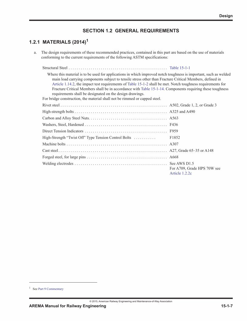
Structural Steel . . . . . . . . . . . . . . . . . . . . . . . . . . . . . . . . . . . . . . . . . . . . . . . . . Table 15-1-1Where this material is to be used for applications in which improved notch toughness is important, such as welded
main load carrying components subject to tensile stress other than Fracture Critical Members, defined in Article 1.14.2, the impact test requirements of Table 15-1-2 shall be met. Notch toughness requirements for Fracture Critical Members shall be in accordance with Table 15-1-14. Components requiring these toughness requirements shall be designated on the design drawings.
For bridge construction, the material shall not be rimmed or capped steel.Rivet steel . . . . . . . . . . . . . . . . . . . . . . . . . . . . . . . . . . . . . . . . . . . . . . . . . . . . . A502, Grade 1, 2, or Grade 3High-strength bolts . . . . . . . . . . . . . . . . . . . . . . . . . . . . . . . . . . . . . . . . . . . . . . A325 and A490Carbon and Alloy Steel Nuts. . . . . . . . . . . . . . . . . . . . . . . . . . . . . . . . . . . . . . . A563Washers, Steel, Hardened . . . . . . . . . . . . . . . . . . . . . . . . . . . . . . . . . . . . . . . . . F436Direct Tension Indicators . . . . . . . . . . . . . . . . . . . . . . . . . . . . . . . . . . . . . . . . . F959High-Strength “Twist Off” Type Tension Control Bolts . . . . . . . . . . . F1852Machine bolts . . . . . . . . . . . . . . . . . . . . . . . . . . . . . . . . . . . . . . . . . . . . . . . . . . A307Cast steel . . . . . . . . . . . . . . . . . . . . . . . . . . . . . . . . . . . . . . . . . . . . . . . . . . . . . . A27, Grade 65–35 or A148Forged steel, for large pins . . . . . . . . . . . . . . . . . . . . . . . . . . . . . . . . . . . . . . . . A668Welding electrodes . . . . . . . . . . . . . . . . . . . . . . . . . . . . . . . . . . . . . . . . . . . . . . See AWS D1.5
For A709, Grade HPS 70W see Article 1.2.2c
Steel Structures
© 2015, American Railway Engineering and Maintenance-of-Way Association
15-1-8 AREMA Manual for Railway Engineering
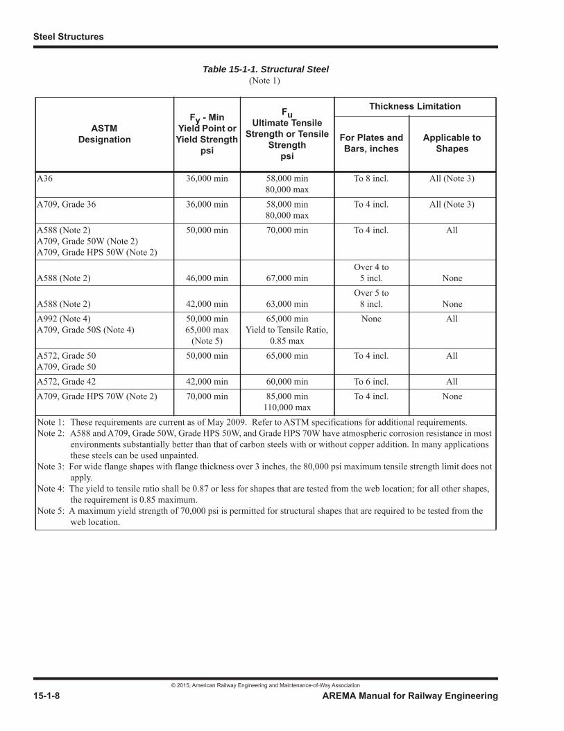
Table 15-1-1. Structural Steel(Note 1)
ASTMDesignation
Fy - Min Yield Point or Yield Strength
psi
FuUltimate Tensile
Strength or Tensile Strength
psi
Thickness Limitation
For Plates and Bars, inches
Applicable to Shapes
A36 36,000 min 58,000 min80,000 max
To 8 incl. All (Note 3)
A709, Grade 36 36,000 min 58,000 min80,000 max
To 4 incl. All (Note 3)
A588 (Note 2)A709, Grade 50W (Note 2)A709, Grade HPS 50W (Note 2)
50,000 min 70,000 min To 4 incl. All
A588 (Note 2) 46,000 min 67,000 minOver 4 to
5 incl. None
A588 (Note 2) 42,000 min 63,000 minOver 5 to
8 incl. NoneA992 (Note 4)A709, Grade 50S (Note 4)
50,000 min65,000 max
(Note 5)
65,000 minYield to Tensile Ratio,
0.85 max
None All
A572, Grade 50A709, Grade 50
50,000 min 65,000 min To 4 incl. All
A572, Grade 42 42,000 min 60,000 min To 6 incl. AllA709, Grade HPS 70W (Note 2) 70,000 min 85,000 min
110,000 maxTo 4 incl. None
Note 1: These requirements are current as of May 2009. Refer to ASTM specifications for additional requirements.Note 2: A588 and A709, Grade 50W, Grade HPS 50W, and Grade HPS 70W have atmospheric corrosion resistance in most
environments substantially better than that of carbon steels with or without copper addition. In many applications these steels can be used unpainted.
Note 3: For wide flange shapes with flange thickness over 3 inches, the 80,000 psi maximum tensile strength limit does not apply.
Note 4: The yield to tensile ratio shall be 0.87 or less for shapes that are tested from the web location; for all other shapes,the requirement is 0.85 maximum.
Note 5: A maximum yield strength of 70,000 psi is permitted for structural shapes that are required to be tested from the web location.
Design
© 2015, American Railway Engineering and Maintenance-of-Way Association
AREMA Manual for Railway Engineering 15-1-9
1
3
4
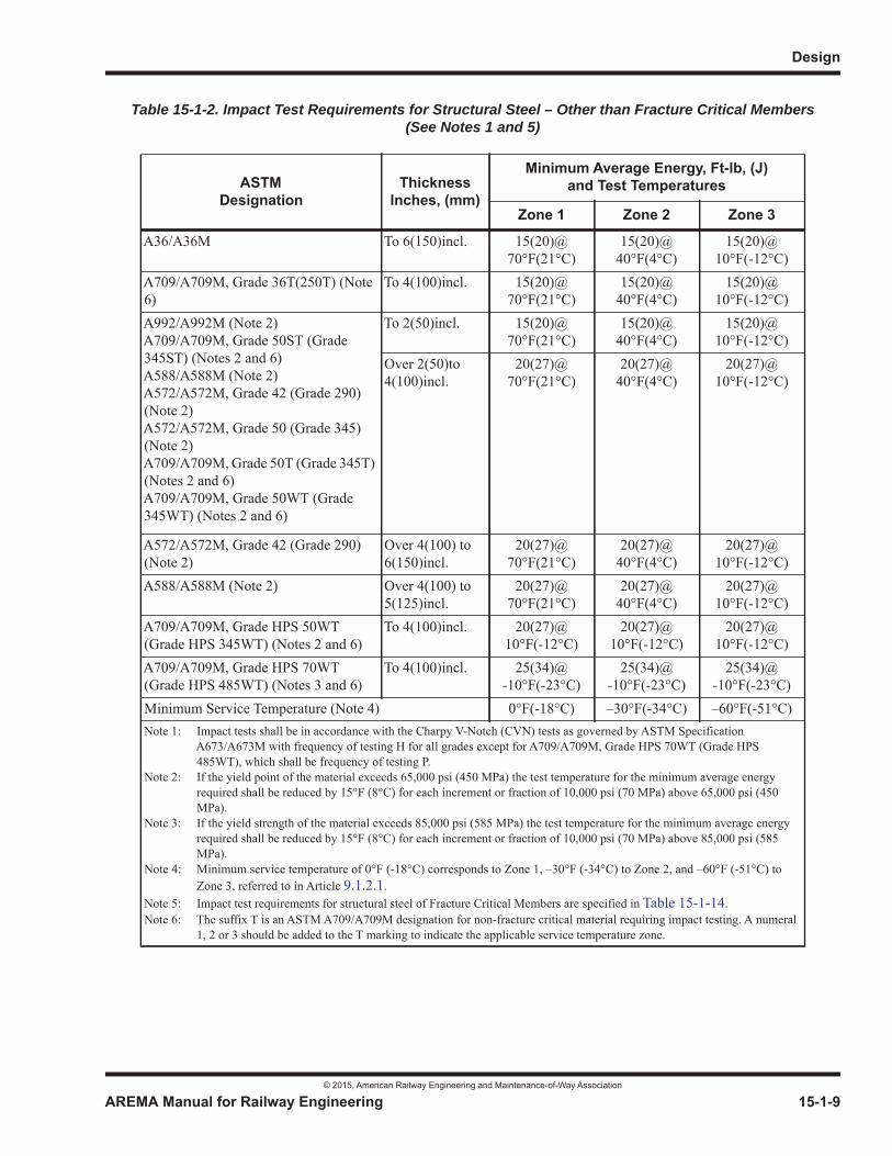
Table 15-1-2. Impact Test Requirements for Structural Steel – Other than Fracture Critical Members (See Notes 1 and 5)
ASTMDesignation
ThicknessInches, (mm)
Minimum Average Energy, Ft-lb, (J)and Test Temperatures
Zone 1 Zone 2 Zone 3
A36/A36M To 6(150)incl. 15(20)@ 70°F(21°C)
15(20)@40°F(4°C)
15(20)@10°F(-12°C)
A709/A709M, Grade 36T(250T) (Note 6)
To 4(100)incl. 15(20)@ 70°F(21°C)
15(20)@40°F(4°C)
15(20)@10°F(-12°C)
A992/A992M (Note 2)A709/A709M, Grade 50ST (Grade 345ST) (Notes 2 and 6)A588/A588M (Note 2)A572/A572M, Grade 42 (Grade 290) (Note 2)A572/A572M, Grade 50 (Grade 345) (Note 2)A709/A709M, Grade 50T (Grade 345T) (Notes 2 and 6)A709/A709M, Grade 50WT (Grade 345WT) (Notes 2 and 6)
To 2(50)incl. 15(20)@ 70°F(21°C)
15(20)@40°F(4°C)
15(20)@10°F(-12°C)
Over 2(50)to4(100)incl.
20(27)@70°F(21°C)
20(27)@40°F(4°C)
20(27)@10°F(-12°C)
A572/A572M, Grade 42 (Grade 290) (Note 2)
Over 4(100) to 6(150)incl.
20(27)@70°F(21°C)
20(27)@40°F(4°C)
20(27)@10°F(-12°C)
A588/A588M (Note 2) Over 4(100) to 5(125)incl.
20(27)@70°F(21°C)
20(27)@40°F(4°C)
20(27)@10°F(-12°C)
A709/A709M, Grade HPS 50WT (Grade HPS 345WT) (Notes 2 and 6)
To 4(100)incl. 20(27)@10°F(-12°C)
20(27)@10°F(-12°C)
20(27)@10°F(-12°C)
A709/A709M, Grade HPS 70WT (Grade HPS 485WT) (Notes 3 and 6)
To 4(100)incl. 25(34)@-10°F(-23°C)
25(34)@-10°F(-23°C)
25(34)@-10°F(-23°C)
Minimum Service Temperature (Note 4) 0°F(-18°C) –30°F(-34°C) –60°F(-51°C)Note 1: Impact tests shall be in accordance with the Charpy V-Notch (CVN) tests as governed by ASTM Specification
A673/A673M with frequency of testing H for all grades except for A709/A709M, Grade HPS 70WT (Grade HPS 485WT), which shall be frequency of testing P.
Note 2: If the yield point of the material exceeds 65,000 psi (450 MPa) the test temperature for the minimum average energy required shall be reduced by 15°F (8°C) for each increment or fraction of 10,000 psi (70 MPa) above 65,000 psi (450 MPa).
Note 3: If the yield strength of the material exceeds 85,000 psi (585 MPa) the test temperature for the minimum average energy required shall be reduced by 15°F (8°C) for each increment or fraction of 10,000 psi (70 MPa) above 85,000 psi (585 MPa).
Note 4: Minimum service temperature of 0°F (-18°C) corresponds to Zone 1, –30°F (-34°C) to Zone 2, and –60°F (-51°C) to Zone 3, referred to in Article 9.1.2.1.
Note 5: Impact test requirements for structural steel of Fracture Critical Members are specified in Table 15-1-14.Note 6: The suffix T is an ASTM A709/A709M designation for non-fracture critical material requiring impact testing. A numeral
1, 2 or 3 should be added to the T marking to indicate the applicable service temperature zone.

Steel Structures
© 2015, American Railway Engineering and Maintenance-of-Way Association
15-1-10 AREMA Manual for Railway Engineering
b. For the properties of steel used in this Manual unless otherwise provided use:
Modulus of Elasticity, E = 29,000,000 psi
Poisson’s Ratio, = 0.3
Shear Modulus, G = 11,200,000 psi
c. Throughout this chapter, the equivalent materials of Table 15-1-3 may be used interchangeably, subject to the additional requirements of Article 1.2.1a. A36 and A588 plate and bar over 4 inches in thickness have no equivalent A709 grade.
d. A588/A588M material in thickness of 5 in. (125 mm) to 8 in. (200 mm) shall be used in compression or other non-toughness applications.
e. Material over 4 inches (100mm) in thickness shall not be used as a Fracture Critical Component.
f. The design requirements for materials of Fracture Critical Members shall further comply with the Fracture Control Plan specified in Section 1.14, Fracture Critical Members. The Engineer shall designate on the plans which members or member components fall in the category of Fracture Critical Members.
1.2.2 WELDING (2003)1 R(2014)
a. Welding shall conform to the applicable provisions of the Bridge Welding Code ANSI/AASHTO/AWS D1.5 of the American Association of State Highway and Transportation Officials and the American Welding Society, herein referred to as AWS D1.5, unless otherwise modified or supplemented by these recommended practices.
b. In applying AWS D1.5 the following substitutions shall be made:
(1) Wherever the designation AASHTO is used it shall be construed to refer to AREMA.
(2) Wherever the term AASHTO Specification or AASHTO Standard Specification for Highway Bridges is used, it shall be construed to refer to this chapter’s recommended practices.
(3) Wherever the word “highway” (as in highway bridge) appears, it shall be interpreted to mean railway or railroad.
(4) Wherever the word “State” (as in State approval, State specification, State inspector, etc.) appears, it shall be construed to refer to the Company as defined in Article 1.1.1 herein.
Table 15-1-3. Equivalent Materials
ASTM A709ASTM
Designation forEquivalent Material
Applicable Thickness
Platesand Bars Shapes
Grade 36 A36 To 4 inches incl. AllGrade 50 A572 Grade 50 To 4 inches incl. AllGrade 50W A588 To 4 inches incl. AllGrade 50S A992 None All
1 See Part 9 Commentary
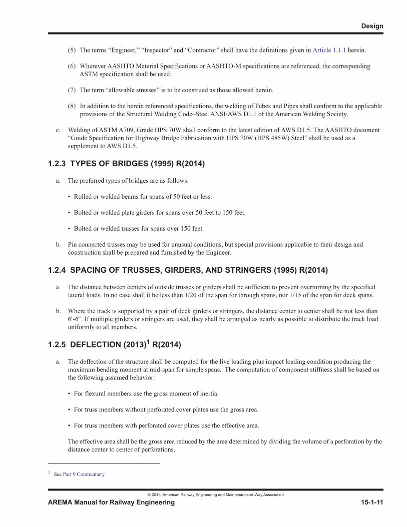
Design
© 2015, American Railway Engineering and Maintenance-of-Way Association
AREMA Manual for Railway Engineering 15-1-11
1
3
4
(5) The terms “Engineer,” “Inspector” and “Contractor” shall have the definitions given in Article 1.1.1 herein.
(6) Wherever AASHTO Material Specifications or AASHTO-M specifications are referenced, the corresponding ASTM specification shall be used.
(7) The term “allowable stresses” is to be construed as those allowed herein.
(8) In addition to the herein referenced specifications, the welding of Tubes and Pipes shall conform to the applicable provisions of the Structural Welding Code–Steel ANSI/AWS D1.1 of the American Welding Society.
c. Welding of ASTM A709, Grade HPS 70W shall conform to the latest edition of AWS D1.5. The AASHTO document “Guide Specification for Highway Bridge Fabrication with HPS 70W (HPS 485W) Steel” shall be used as a supplement to AWS D1.5.
1.2.3 TYPES OF BRIDGES (1995) R(2014)
a. The preferred types of bridges are as follows:
• Rolled or welded beams for spans of 50 feet or less.
• Bolted or welded plate girders for spans over 50 feet to 150 feet.
• Bolted or welded trusses for spans over 150 feet.
b. Pin connected trusses may be used for unusual conditions, but special provisions applicable to their design and construction shall be prepared and furnished by the Engineer.
1.2.4 SPACING OF TRUSSES, GIRDERS, AND STRINGERS (1995) R(2014)
a. The distance between centers of outside trusses or girders shall be sufficient to prevent overturning by the specified lateral loads. In no case shall it be less than 1/20 of the span for through spans, nor 1/15 of the span for deck spans.
b. Where the track is supported by a pair of deck girders or stringers, the distance center to center shall be not less than 6 -6 . If multiple girders or stringers are used, they shall be arranged as nearly as possible to distribute the track load uniformly to all members.
1.2.5 DEFLECTION (2013)1 R(2014)
a. The deflection of the structure shall be computed for the live loading plus impact loading condition producing the maximum bending moment at mid-span for simple spans. The computation of component stiffness shall be based on the following assumed behavior:
• For flexural members use the gross moment of inertia.
• For truss members without perforated cover plates use the gross area.
• For truss members with perforated cover plates use the effective area.
The effective area shall be the gross area reduced by the area determined by dividing the volume of a perforation by the distance center to center of perforations.
1 See Part 9 Commentary

Steel Structures
© 2015, American Railway Engineering and Maintenance-of-Way Association
15-1-12 AREMA Manual for Railway Engineering
b. The structure shall be so designed that the computed deflection shall not exceed 1/640 of the span length center to center of bearings for simple spans.
c. Lateral deflection of the structure shall be limited such that the mid-ordinate of any 62 foot (19 m) chord shall not exceed 3/8 inch (10 mm) for tangent track. On curved track, lateral deflection shall be limited to 1/4 inch (6 mm) as measured on any 31 foot (9.5 meter) chord, and not more than 5/16 inch (8 mm) on any 62 foot (19 meter) chord.
The lateral deflection calculated is to be the maximum lateral deflection at track level due to all applicable lateral forces and loads specified in Section 1.3 excepting those due to earthquake (seismic) or wind on unloaded bridges. The maximum lateral deflection at track level shall be referenced to the point on a vertical plane below which lateral deflection is restrained (i.e. base of structure, span bearings, bottom flange of girder; depending on the lateral deflection being considered).
1.2.6 CLEARANCES (1995)1 R(2014)
a. The clearances on straight track shall be not less than those shown in Figure 15-1-1. On curved track, the lateral clearance each side of track centerline shall be increased 1-1/2 inches per degree of curvature. When the fixed obstruction is on tangent track, but the track is curved within 80 feet of the obstruction, the lateral clearance each side of track centerline shall be increased as shown in Table 15-1-4.
b. Where legal requirements specify greater clearances, such requirements shall govern.
c. The superelevation of the outer rail shall be specified by the Engineer. The distance from the top of rail to the top of tie shall be assumed as 8 inches, unless otherwise specified by the Engineer.
d. Where there are plans for electrification, the minimum vertical clearance shall be increased to that specified in Chapter28, Clearances.
e. The clearances shown are for new construction. Clearances for reconstruction work or for alterations are dependent on existing physical conditions and, where reasonably possible, should be improved to meet the requirements for new construction.
1 See Part 9 Commentary
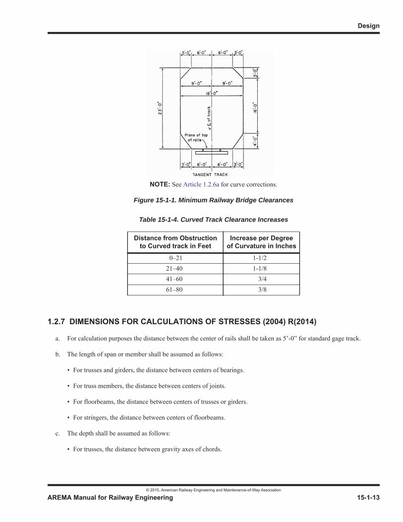
Design
© 2015, American Railway Engineering and Maintenance-of-Way Association
AREMA Manual for Railway Engineering 15-1-13
1
3
4
1.2.7 DIMENSIONS FOR CALCULATIONS OF STRESSES (2004) R(2014)
a. For calculation purposes the distance between the center of rails shall be taken as 5’-0” for standard gage track.
b. The length of span or member shall be assumed as follows:
• For trusses and girders, the distance between centers of bearings.
• For truss members, the distance between centers of joints.
• For floorbeams, the distance between centers of trusses or girders.
• For stringers, the distance between centers of floorbeams.
c. The depth shall be assumed as follows:
• For trusses, the distance between gravity axes of chords.
Table 15-1-4. Curved Track Clearance Increases
Distance from Obstructionto Curved track in Feet
Increase per Degreeof Curvature in Inches
0–21 1-1/221–40 1-1/841–60 3/461–80 3/8
NOTE: See Article 1.2.6a for curve corrections.
Figure 15-1-1. Minimum Railway Bridge Clearances
Steel Structures
© 2015, American Railway Engineering and Maintenance-of-Way Association
15-1-14 AREMA Manual for Railway Engineering
1.2.8 SKEW BRIDGES (1994) R(2014)
At the ends of skew bridges, the ends of the supports for each track shall be perpendicular to the centerline of track.
1.2.9 OPEN DECK BRIDGE TIES (1994) R(2014)
Timber bridge ties shall meet the requirements of Chapter 7, Timber Structures and be not less than 10 feet long and spaced such that the gap between the ties is not more than 6 inches. They shall be secured against bunching, skewing, and uplift.
1.2.10 CAMBER (1995) R(2014)
The camber of trusses shall be equal to the deflection produced by the dead load plus a live load of 3,000 lb per foot of track.The camber of plate girders more than 90 feet in length shall be equal to the deflection produced by the dead load only. Plate girders 90 feet or less in length and rolled beams need not be cambered.
1.2.11 NAMEPLATES (1995) R(2014)
An approved nameplate showing the name of the fabricator and the year of construction shall be attached to one end of each span at a point convenient for inspection.
1.2.12 STEEL INNER GUARD RAILS AND GUARD TIMBERS (1995) R(2014)
Recommendations pertaining to the use of steel inner guard rails and guard timbers are contained inChapter 7, Timber Structures; Part 4, Construction and Maintenance of Timber Structures, Section 4.10, Use of Guard Rails and Guard Timbers (2004).
1.2.13 PROVISION FOR EXPANSION (2008) R(2014)
The design shall be such as to allow for the change in length of the spans resulting from change in temperature, at the minimum rate of 1 inch in 100 feet. Provision shall be made for change in length of the span resulting from live load. In spansmore than 300 feet long, allowance shall be made for expansion of the floor system. For specific provisions for bearings, see Part 5.
1.2.14 SPECIAL TRACKWORK ON BRIDGES (2015)1
Switches, crossing diamonds, expansion joints, etc. should not be placed on bridges. Where possible switches, crossing diamonds, and other special trackwork should be located at least 200 feet from the backwalls. Location of expansion joints should be in accordance with Part 8, Miscellaneous.
If it is absolutely necessary to locate special trackwork on bridges, impact loads in accordance with Part 6, Movable Bridges,Articles 6.3.2d and 6.3.3 should be considered. See Commentary.
SECTION 1.3 LOADS, FORCES AND STRESSES
1.3.1 LOADS AND FORCES (1995) R(2014)
a. Bridges shall be proportioned for the following:
1 See Part 9 Commentary
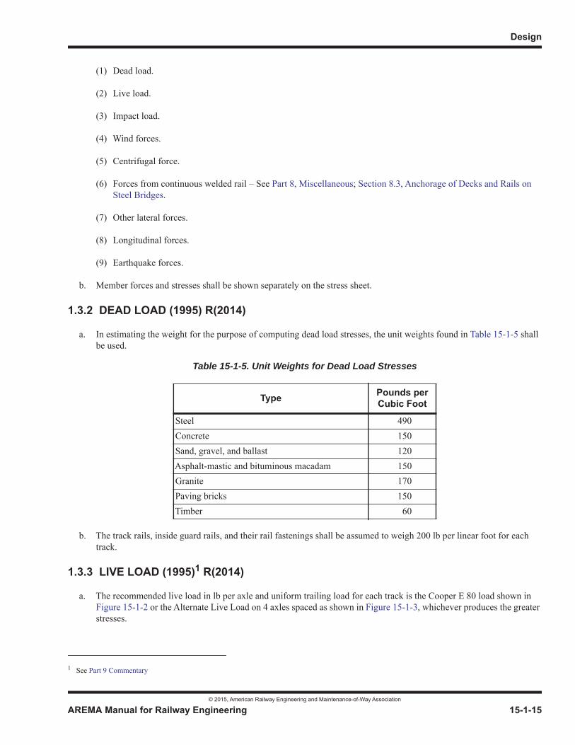
Design
© 2015, American Railway Engineering and Maintenance-of-Way Association
AREMA Manual for Railway Engineering 15-1-15
1
3
4
(1) Dead load.
(2) Live load.
(3) Impact load.
(4) Wind forces.
(5) Centrifugal force.
(6) Forces from continuous welded rail – See Part 8, Miscellaneous; Section 8.3, Anchorage of Decks and Rails on Steel Bridges.
(7) Other lateral forces.
(8) Longitudinal forces.
(9) Earthquake forces.
b. Member forces and stresses shall be shown separately on the stress sheet.
1.3.2 DEAD LOAD (1995) R(2014)
a. In estimating the weight for the purpose of computing dead load stresses, the unit weights found in Table 15-1-5 shall be used.
b. The track rails, inside guard rails, and their rail fastenings shall be assumed to weigh 200 lb per linear foot for each track.
1.3.3 LIVE LOAD (1995)1 R(2014)
a. The recommended live load in lb per axle and uniform trailing load for each track is the Cooper E 80 load shown in Figure 15-1-2 or the Alternate Live Load on 4 axles spaced as shown in Figure 15-1-3, whichever produces the greater stresses.
Table 15-1-5. Unit Weights for Dead Load Stresses
Type Pounds perCubic Foot
Steel 490Concrete 150Sand, gravel, and ballast 120Asphalt-mastic and bituminous macadam 150Granite 170Paving bricks 150Timber 60
1 See Part 9 Commentary
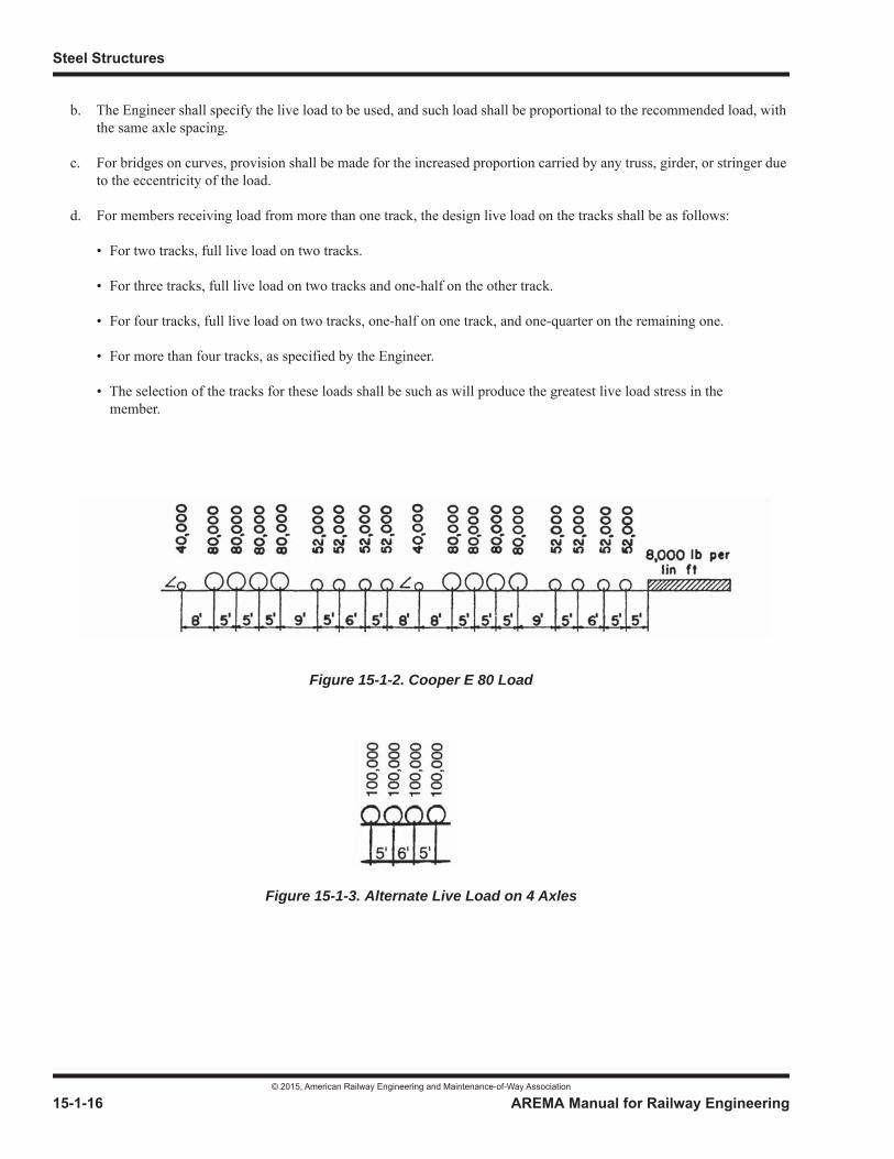
Steel Structures
© 2015, American Railway Engineering and Maintenance-of-Way Association
15-1-16 AREMA Manual for Railway Engineering
b. The Engineer shall specify the live load to be used, and such load shall be proportional to the recommended load, with the same axle spacing.
c. For bridges on curves, provision shall be made for the increased proportion carried by any truss, girder, or stringer due to the eccentricity of the load.
d. For members receiving load from more than one track, the design live load on the tracks shall be as follows:
• For two tracks, full live load on two tracks.
• For three tracks, full live load on two tracks and one-half on the other track.
• For four tracks, full live load on two tracks, one-half on one track, and one-quarter on the remaining one.
• For more than four tracks, as specified by the Engineer.
• The selection of the tracks for these loads shall be such as will produce the greatest live load stress in the member.
Figure 15-1-2. Cooper E 80 Load
Figure 15-1-3. Alternate Live Load on 4 Axles
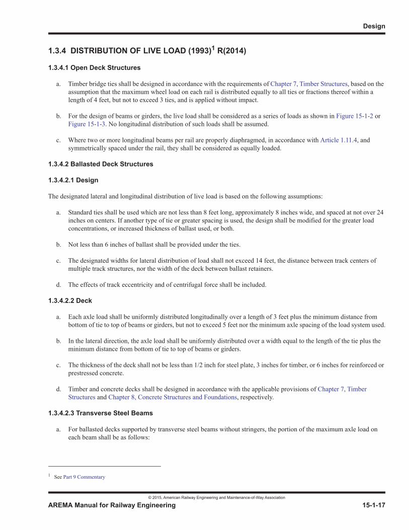
Design
© 2015, American Railway Engineering and Maintenance-of-Way Association
AREMA Manual for Railway Engineering 15-1-17
1
3
4
1.3.4 DISTRIBUTION OF LIVE LOAD (1993)1 R(2014)
1.3.4.1 Open Deck Structures
a. Timber bridge ties shall be designed in accordance with the requirements of Chapter 7, Timber Structures, based on the assumption that the maximum wheel load on each rail is distributed equally to all ties or fractions thereof within a length of 4 feet, but not to exceed 3 ties, and is applied without impact.
b. For the design of beams or girders, the live load shall be considered as a series of loads as shown in Figure 15-1-2 or Figure 15-1-3. No longitudinal distribution of such loads shall be assumed.
c. Where two or more longitudinal beams per rail are properly diaphragmed, in accordance with Article 1.11.4, and symmetrically spaced under the rail, they shall be considered as equally loaded.
1.3.4.2 Ballasted Deck Structures
1.3.4.2.1 Design
The designated lateral and longitudinal distribution of live load is based on the following assumptions:
a. Standard ties shall be used which are not less than 8 feet long, approximately 8 inches wide, and spaced at not over 24 inches on centers. If another type of tie or greater spacing is used, the design shall be modified for the greater load concentrations, or increased thickness of ballast used, or both.
b. Not less than 6 inches of ballast shall be provided under the ties.
c. The designated widths for lateral distribution of load shall not exceed 14 feet, the distance between track centers of multiple track structures, nor the width of the deck between ballast retainers.
d. The effects of track eccentricity and of centrifugal force shall be included.
1.3.4.2.2 Deck
a. Each axle load shall be uniformly distributed longitudinally over a length of 3 feet plus the minimum distance from bottom of tie to top of beams or girders, but not to exceed 5 feet nor the minimum axle spacing of the load system used.
b. In the lateral direction, the axle load shall be uniformly distributed over a width equal to the length of the tie plus the minimum distance from bottom of tie to top of beams or girders.
c. The thickness of the deck shall not be less than 1/2 inch for steel plate, 3 inches for timber, or 6 inches for reinforced orprestressed concrete.
d. Timber and concrete decks shall be designed in accordance with the applicable provisions of Chapter 7, Timber Structures and Chapter 8, Concrete Structures and Foundations, respectively.
1.3.4.2.3 Transverse Steel Beams
a. For ballasted decks supported by transverse steel beams without stringers, the portion of the maximum axle load on each beam shall be as follows:
1 See Part 9 Commentary
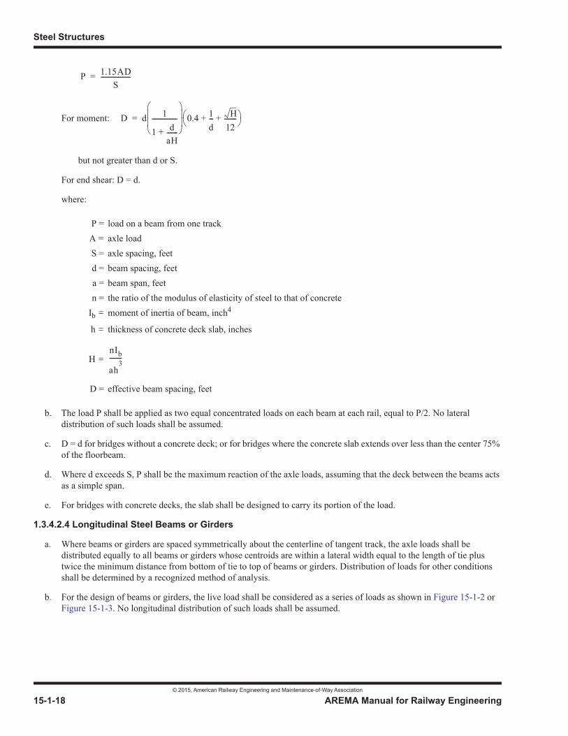
Steel Structures
© 2015, American Railway Engineering and Maintenance-of-Way Association
15-1-18 AREMA Manual for Railway Engineering
For moment:
but not greater than d or S.
For end shear: D = d.
where:
b. The load P shall be applied as two equal concentrated loads on each beam at each rail, equal to P/2. No lateral distribution of such loads shall be assumed.
c. D = d for bridges without a concrete deck; or for bridges where the concrete slab extends over less than the center 75% of the floorbeam.
d. Where d exceeds S, P shall be the maximum reaction of the axle loads, assuming that the deck between the beams acts as a simple span.
e. For bridges with concrete decks, the slab shall be designed to carry its portion of the load.
1.3.4.2.4 Longitudinal Steel Beams or Girders
a. Where beams or girders are spaced symmetrically about the centerline of tangent track, the axle loads shall be distributed equally to all beams or girders whose centroids are within a lateral width equal to the length of tie plus twice the minimum distance from bottom of tie to top of beams or girders. Distribution of loads for other conditions shall be determined by a recognized method of analysis.
b. For the design of beams or girders, the live load shall be considered as a series of loads as shown in Figure 15-1-2 or Figure 15-1-3. No longitudinal distribution of such loads shall be assumed.
P = load on a beam from one trackA = axle loadS = axle spacing, feetd = beam spacing, feeta = beam span, feetn = the ratio of the modulus of elasticity of steel to that of concrete
Ib = moment of inertia of beam, inch4
h = thickness of concrete deck slab, inches
H =
D = effective beam spacing, feet
P 1.15ADS
-------------------=
D d 1
1 daH-------+
---------------- 0.4 1d--- H
12--------+ +=
nIb
ah3
--------
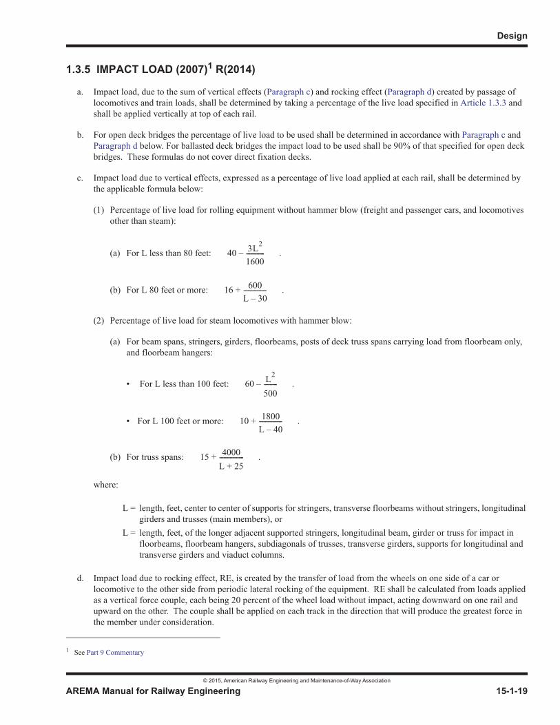
Design
© 2015, American Railway Engineering and Maintenance-of-Way Association
AREMA Manual for Railway Engineering 15-1-19
1
3
4
1.3.5 IMPACT LOAD (2007)1 R(2014)
a. Impact load, due to the sum of vertical effects (Paragraph c) and rocking effect (Paragraph d) created by passage of locomotives and train loads, shall be determined by taking a percentage of the live load specified in Article 1.3.3 and shall be applied vertically at top of each rail.
b. For open deck bridges the percentage of live load to be used shall be determined in accordance with Paragraph c and Paragraph d below. For ballasted deck bridges the impact load to be used shall be 90% of that specified for open deck bridges. These formulas do not cover direct fixation decks.
c. Impact load due to vertical effects, expressed as a percentage of live load applied at each rail, shall be determined by the applicable formula below:
(1) Percentage of live load for rolling equipment without hammer blow (freight and passenger cars, and locomotives other than steam):
(a) For L less than 80 feet: .
(b) For L 80 feet or more: .
(2) Percentage of live load for steam locomotives with hammer blow:
(a) For beam spans, stringers, girders, floorbeams, posts of deck truss spans carrying load from floorbeam only, and floorbeam hangers:
• For L less than 100 feet: .
• For L 100 feet or more: .
(b) For truss spans: .
where:
d. Impact load due to rocking effect, RE, is created by the transfer of load from the wheels on one side of a car or locomotive to the other side from periodic lateral rocking of the equipment. RE shall be calculated from loads applied as a vertical force couple, each being 20 percent of the wheel load without impact, acting downward on one rail and upward on the other. The couple shall be applied on each track in the direction that will produce the greatest force in the member under consideration.
1 See Part 9 Commentary
L = length, feet, center to center of supports for stringers, transverse floorbeams without stringers, longitudinal girders and trusses (main members), or
L = length, feet, of the longer adjacent supported stringers, longitudinal beam, girder or truss for impact in floorbeams, floorbeam hangers, subdiagonals of trusses, transverse girders, supports for longitudinal and transverse girders and viaduct columns.
40 3L2
1600------------–
16 600L 30–---------------+
60 L2
500---------–
10 1800L 40–---------------+
15 4000L 25+----------------+
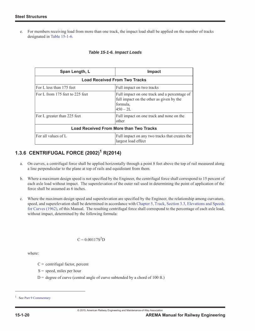
Steel Structures
© 2015, American Railway Engineering and Maintenance-of-Way Association
15-1-20 AREMA Manual for Railway Engineering
e. For members receiving load from more than one track, the impact load shall be applied on the number of tracks designated in Table 15-1-6.
1.3.6 CENTRIFUGAL FORCE (2002)1 R(2014)
a. On curves, a centrifugal force shall be applied horizontally through a point 8 feet above the top of rail measured along a line perpendicular to the plane at top of rails and equidistant from them.
b. Where a maximum design speed is not specified by the Engineer, the centrifugal force shall correspond to 15 percent of each axle load without impact. The superelevation of the outer rail used in determining the point of application of the force shall be assumed as 6 inches.
c. Where the maximum design speed and superelevation are specified by the Engineer, the relationship among curvature, speed, and superelevation shall be determined in accordance with Chapter 5, Track, Section 3.3, Elevations and Speeds for Curves (1962), of this Manual. The resulting centrifugal force shall correspond to the percentage of each axle load, without impact, determined by the following formula:
where:
Span Length, L Impact
Load Received From Two Tracks
For L less than 175 feet Full impact on two tracksFor L from 175 feet to 225 feet Full impact on one track and a percentage of
full impact on the other as given by the formula,450 – 2L
For L greater than 225 feet Full impact on one track and none on the other
Load Received From More than Two Tracks
For all values of L Full impact on any two tracks that creates the largest load effect
1 See Part 9 Commentary
C = centrifugal factor, percentS = speed, miles per hourD = degree of curve (central angle of curve subtended by a chord of 100 ft.)
Table 15-1-6. Impact Loads
C = 0.00117S2D
Design
© 2015, American Railway Engineering and Maintenance-of-Way Association
AREMA Manual for Railway Engineering 15-1-21
1
3
4
The superelevation of the outer rail used in determining the point of application of the force shall be as specified by the Engineer.
d. On curves, each axle load on each track shall be applied vertically through the point defined above. Impact load shall be applied as specified in Article 1.3.5.
e. On curves, the forces in a stringer, girder or truss toward the outside and inside of curve shall be determined separately, and the greater section required shall be used on both sides. For members toward the outside of curve, the full impact load of Article 1.3.5 and the centrifugal force as defined in Paragraph a shall apply. For members toward the inside of curve, any effect of the centrifugal force shall be omitted.
1.3.7 WIND FORCES ON LOADED BRIDGE (2003)1 R(2014)
In general, the wind force shall be considered as a moving load acting in any horizontal direction. As a minimum, the bridge shall be designed for laterally and longitudinally applied wind forces acting independently as follows:
a. On the train, the lateral wind force shall be taken at 300 lb. per linear foot applied normal to the train on one track at a distance of 8 feet above top of rail.
b. On the bridge, lateral wind pressure shall be taken at 30 lb. per square foot normal to the following surfaces:
(1) For girder spans, 1.5 times the vertical projection of the span.
(2) For truss spans, the vertical projection of the span plus any portion of leeward trusses not shielded by the floor system.
(3) For viaduct towers and bents, the vertical projection of all windward and leeward columns and bracing.
c. The lateral wind force on girder and truss spans, however, shall not be taken as less than 200 lb. per foot for the loaded chord or flange and 150 lb. per foot for the unloaded chord or flange, neglecting the wind force on the floor system.
d. The longitudinal wind force on spans shall be taken as:
(1) For girder spans, 25 percent of the lateral wind force.
(2) For truss spans, 50 percent of the lateral wind force.
(3) For viaduct towers and bents, 30 lb. per square foot on the vertical projection of all windward and leeward columns and bracing.
1.3.8 WIND FORCES ON UNLOADED BRIDGE (2006)2 R(2014)
In general, the wind force shall be considered as a moving load acting in any horizontal direction. As a minimum, the bridge shall be designed for laterally and longitudinally applied wind forces acting independently as follows:
a. The lateral wind force on the unloaded bridge shall be taken as 50 lb per square foot of surface as defined in Article 1.3.7b.
b. The longitudinal wind force on the unloaded spans shall be taken as:
1 See Part 9 Commentary2 See Part 9 Commentary
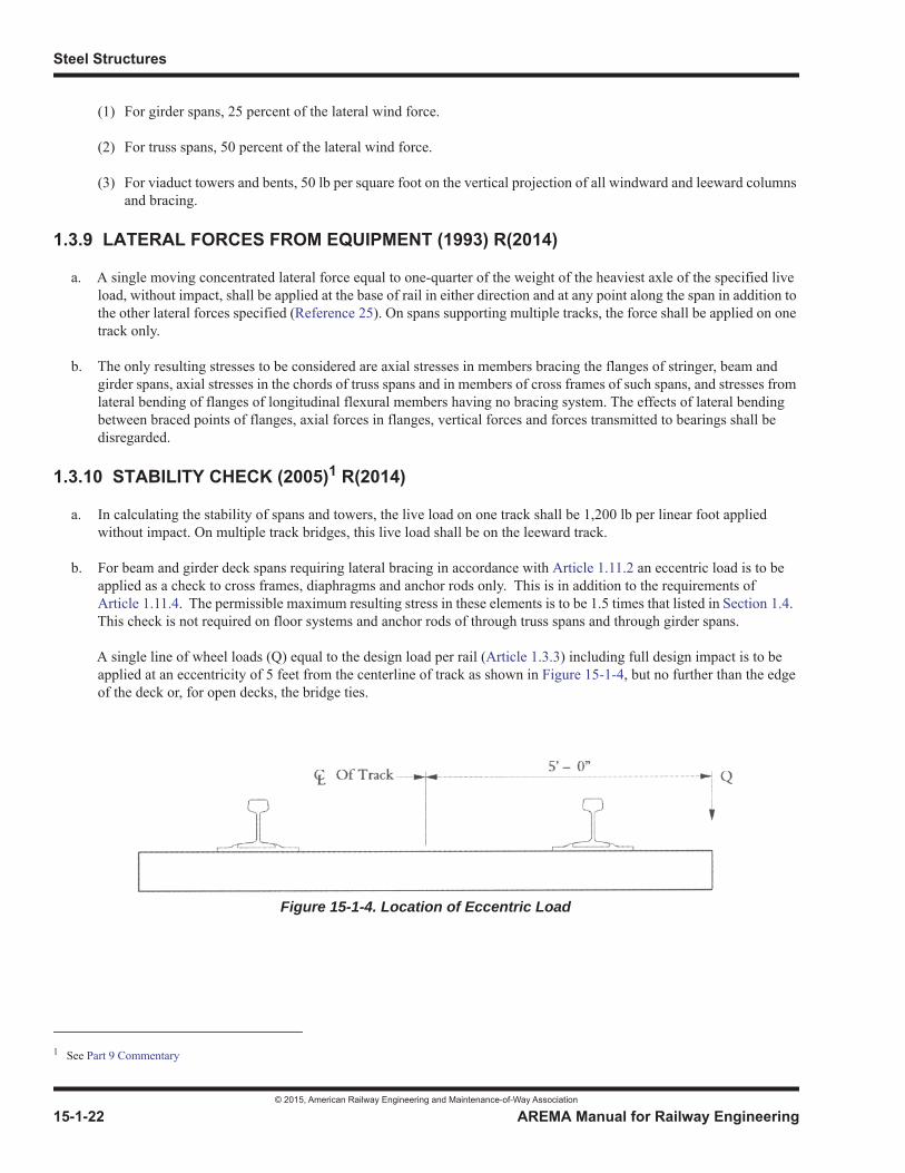
Steel Structures
© 2015, American Railway Engineering and Maintenance-of-Way Association
15-1-22 AREMA Manual for Railway Engineering
(1) For girder spans, 25 percent of the lateral wind force.
(2) For truss spans, 50 percent of the lateral wind force.
(3) For viaduct towers and bents, 50 lb per square foot on the vertical projection of all windward and leeward columns and bracing.
1.3.9 LATERAL FORCES FROM EQUIPMENT (1993) R(2014)
a. A single moving concentrated lateral force equal to one-quarter of the weight of the heaviest axle of the specified live load, without impact, shall be applied at the base of rail in either direction and at any point along the span in addition to the other lateral forces specified (Reference 25). On spans supporting multiple tracks, the force shall be applied on one track only.
b. The only resulting stresses to be considered are axial stresses in members bracing the flanges of stringer, beam and girder spans, axial stresses in the chords of truss spans and in members of cross frames of such spans, and stresses from lateral bending of flanges of longitudinal flexural members having no bracing system. The effects of lateral bending between braced points of flanges, axial forces in flanges, vertical forces and forces transmitted to bearings shall be disregarded.
1.3.10 STABILITY CHECK (2005)1 R(2014)
a. In calculating the stability of spans and towers, the live load on one track shall be 1,200 lb per linear foot applied without impact. On multiple track bridges, this live load shall be on the leeward track.
b. For beam and girder deck spans requiring lateral bracing in accordance with Article 1.11.2 an eccentric load is to be applied as a check to cross frames, diaphragms and anchor rods only. This is in addition to the requirements of Article 1.11.4. The permissible maximum resulting stress in these elements is to be 1.5 times that listed in Section 1.4.This check is not required on floor systems and anchor rods of through truss spans and through girder spans.
A single line of wheel loads (Q) equal to the design load per rail (Article 1.3.3) including full design impact is to be applied at an eccentricity of 5 feet from the centerline of track as shown in Figure 15-1-4, but no further than the edge of the deck or, for open decks, the bridge ties.
1 See Part 9 Commentary
Figure 15-1-4. Location of Eccentric Load

Design
© 2015, American Railway Engineering and Maintenance-of-Way Association
AREMA Manual for Railway Engineering 15-1-23
1
3
4
1.3.11 BRACING BETWEEN COMPRESSION MEMBERS (2000) R(2014)
The lateral bracing of the compression chords or flanges of trusses, deck girders and through girders and between the posts ofviaduct towers shall be proportioned for a transverse shear force in any panel equal to 2.5% of the total axial force in both members in that panel, in addition to the shear force from the specified lateral loads.
1.3.12 LONGITUDINAL FORCES (2005)1 R(2014)
a. The longitudinal force for E-80 loading shall be taken as the larger of:
Force due to braking, as prescribed by the following equation, acting 8 feet (2500 mm) above top of rail:
Force due to traction, as prescribed by the following equation, acting 3 feet (900 mm) above top of rail:
where:
L is length in feet (meters) of the portion of the bridge under consideration.
For design loads other than E-80, these forces shall be scaled proportionally. The points of force application shall not be changed.
b. The longitudinal force shall be distributed to the various components of the supporting structure, taking into account their relative stiffness. The soil resistance of the backfill behind the abutments shall be utilized where applicable. The mechanisms (rail, bearings, load transfer devices, etc.) available to transfer the force to the various components shall also be considered.
c. For multiple track structures, longitudinal forces shall be applied as per Article 1.3.3d.
1.3.13 FATIGUE (2015)2
a. Members and connections subjected to repeated fluctuations of stress shall meet the fatigue requirements of this article as well as the strength requirements of Section 1.4, Basic Allowable Stresses.
1 See Part 9 Commentary
Longitudinal braking force (kips) = 45 + 1.2 L(Longitudinal braking force (kN) = 200 + 17.5 L)
2 See Part 9 Commentary
25 LLongitudinal traction force (kips) =
200 L(Longitudinal traction force (kN) =
Steel Structures
© 2015, American Railway Engineering and Maintenance-of-Way Association
15-1-24 AREMA Manual for Railway Engineering
b. The major factors governing fatigue strength at a particular location of a member or connection are the number of stress cycles, the magnitude of the stress range, and the relevant Fatigue Detail Category. For the effects of secondary stresses see Article 1.3.13 and associated commentary.
c. The number of stress cycles, N, to be considered shall be selected from Table 15-1-7, unless traffic surveys or other considerations indicate otherwise, N depends on the span length in the case of longitudinal members, and on the number of tracks in the case of floorbeams, hangers, and certain truss members.
d. Mean Impact Load for fatigue design shall be taken as the Table 15-1-8 percentages of the impact load specified in Article 1.3.5. Mean Impact reductions shall not apply to members whose load or impact is increased in Part 6, Movable Bridges, Articles 6.3.2 and 6.3.3 or any structure where the rail is not continuously fastened across the member; nor shall mean impact be applied to machinery and similar parts of movable structures unless indicated in Part 6. Members supporting special trackwork (see article 1.2.14) shall not have impacts reduced by the mean impact percentages tabulated in this article.
e. The live load for fatigue design is specified in Article 1.3.3.
f. The live load stress range, SR, is defined as the algebraic difference between the maximum and minimum calculated stress due to live load, mean impact load, and centrifugal load. Fatigue need not be considered when the combination of live load and dead load results in net compressive stresses (except as noted in Article 9.1.3.13k).
The stress range, SR, shall be computed on the basis of the effective net section or the effective gross section as shown in Table 15-1-9.
g. Examples of various construction details are illustrated and categorized in Table 15-1-9.
h. The design stress range shall not exceed the allowable fatigue stress range. SRfat, listed in Table 15-1-10.
i. Fracture is not necessarily the result of fatigue, yet fatigue of a member can lead to fracture. As such, low fatigue resistant details should be avoided on Fracture Critical Members. Detail Category E and E’ details shall not be used on fracture critical members, and Detail Category D details shall be discouraged and used only with caution.
j. For span lengths exceeding 300 feet, a special analysis of the number of relevant cycles is required (see Part 9, Commentary).
k. Load paths that are sufficiently rigid to transmit all forces shall be provided by connecting all transverse members to appropriate components comprising the cross-section of the longitudinal member to deal with distortion-induced fatigue. To control web buckling and elastic flexing of the web, the provision of Article 1.7.3 must be satisfied.

Design
© 2015, American Railway Engineering and Maintenance-of-Way Association
AREMA Manual for Railway Engineering 15-1-25
1
3
4
Table 15-1-7. Number of Stress Cycles, N
Member DescriptionSpan Length, L of FlexuralMember or Truss or Load
Condition
Constant StressCycles, N
Classification I
Longitudinal flexural members and their connections. Truss chord members including end posts, and their connections
L > 100 feet 2,000,000L 100 feet > 2,000,000
Classification II
Floorbeams and their connections. Truss hangers and sub-diagonals that carry floorbeam reactions only, and their connections. Truss web members and their connections.
Two Tracks Loaded 2,000,000One Track Loaded > 2,000,000
Note: This table is based on bridges designed for the live loading specified in Article 1.3.13e. For bridges designed for other live loadings see Part 9, Commentary, Article 9.1.3.13.
Table 15-1-8. Assumed Mean Impact Load Percentages
Member Percentage
Members with loaded Lengths 10 feet (3m) and no load sharing
HangersOther Truss members
Beams, Stringers, Girders and Floorbeams
65%40%65%35%
Note: Where bridges are designed for operation of trains handling a large percentage of cars with flat or out of round wheels which increase impact and/or poor track which increases impact, and the loaded length of the member is less than 80 feet (24m), the mean impact should be 100% of the design impact.
Steel Structures
© 2015, American Railway Engineering and Maintenance-of-Way Association
15-1-26 AREMA Manual for Railway Engineering
1.3.13.1 High-Strength Bolts Subjected to Tensile Fatigue Loading
Fully pretensioned high-strength bolts subjected to tensile fatigue loading shall be designed for the combined external load andprying force using the following allowable tensile stress ranges:
A 325 Bolts in axial tension: 31,000 psi on the tensile stress area (see Table 15-1-9, Section 8.2) at the threads
A 490 Bolts in axial tension: 38,000 psi on the tensile stress area (see Table 15-1-9, Section 8.2) at the threads
In no case shall the prying force exceed 20% of the total externally applied load.
1.3.13.2 Anchor Bolts Subject to Tensile Fatigue Loading1
Anchor bolts at locations where the bolts will be subject to fluctuating tensile stress calculated on the tensile stress area shallbe designed to transfer the applied forces. All anchor bolts in the bolt pattern resisting tension from the applicable horizontaland vertical live load forces shall be designed for fatigue in accordance with Table 15-1-9, Section 8 for the allowable fatigue stress range limit of 7 ksi. After the grout pad is completed, anchor bolts intended for resistance to uplift shall be pretensionedto a minimum of 0.8 Fy but need not be more than 100 kips unless calculations by the Engineer indicate a need for a higher pretension force. The pretension shall also be sufficient to ensure that separation from the grout pad will not occur.
Anchor bolts shall be ASTM F1554, Grade 55 or Grade 105. See Commentary for discussion of stainless steel for anchor bolts.
1 See Part 9 Commentary
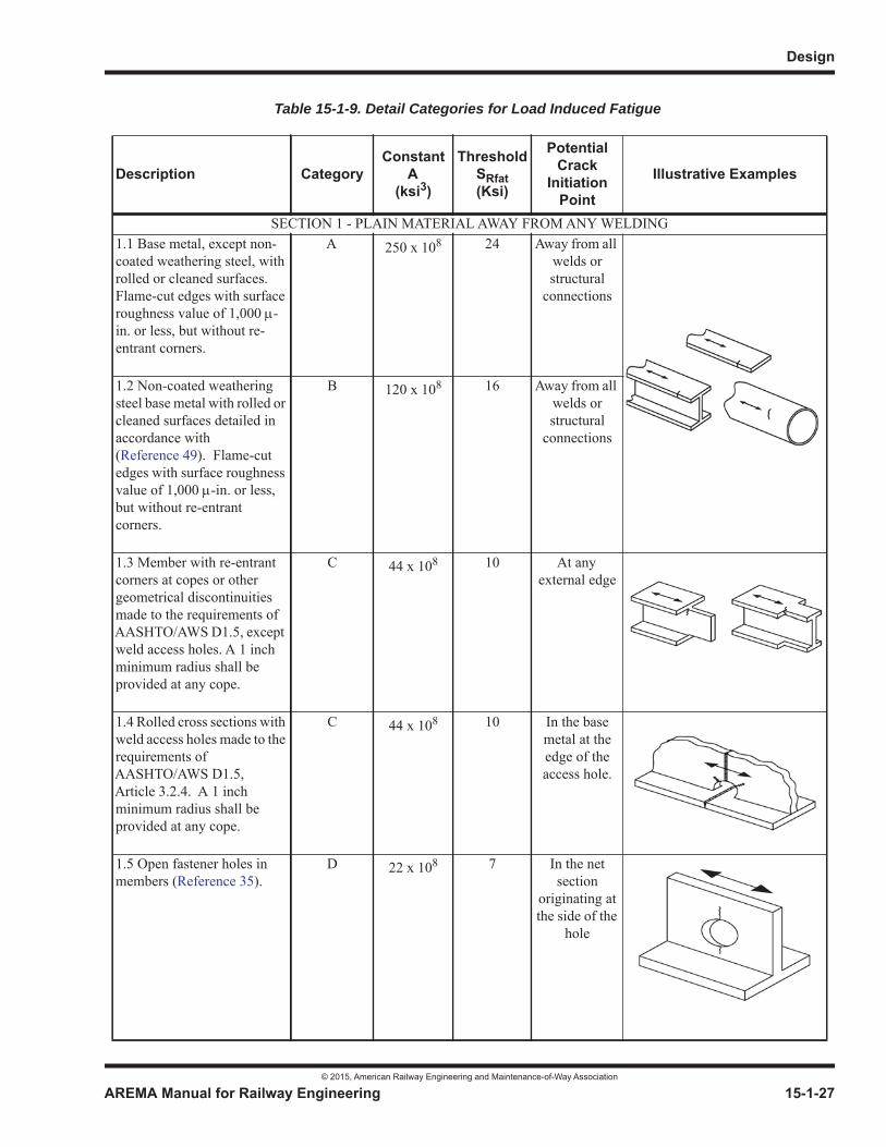
Design
© 2015, American Railway Engineering and Maintenance-of-Way Association
AREMA Manual for Railway Engineering 15-1-27
1
3
4
Table 15-1-9. Detail Categories for Load Induced Fatigue
Description CategoryConstant
A(ksi3)
ThresholdSRfat(Ksi)
PotentialCrack
InitiationPoint
Illustrative Examples
SECTION 1 - PLAIN MATERIAL AWAY FROM ANY WELDING1.1 Base metal, except non-coated weathering steel, with rolled or cleaned surfaces.Flame-cut edges with surface roughness value of 1,000 -in. or less, but without re-entrant corners.
A 250 x 108 24 Away from all welds or structural
connections
1.2 Non-coated weathering steel base metal with rolled or cleaned surfaces detailed in accordance with (Reference 49). Flame-cut edges with surface roughness value of 1,000 -in. or less, but without re-entrant corners.
B 120 x 108 16 Away from all welds or structural
connections
1.3 Member with re-entrant corners at copes or other geometrical discontinuities made to the requirements of AASHTO/AWS D1.5, except weld access holes. A 1 inch minimum radius shall be provided at any cope.
C 44 x 108 10 At any external edge
1.4 Rolled cross sections with weld access holes made to the requirements of AASHTO/AWS D1.5, Article 3.2.4. A 1 inch minimum radius shall be provided at any cope.
C 44 x 108 10 In the base metal at the edge of the access hole.
1.5 Open fastener holes in members (Reference 35).
D 22 x 108 7 In the net section
originating at the side of the
hole
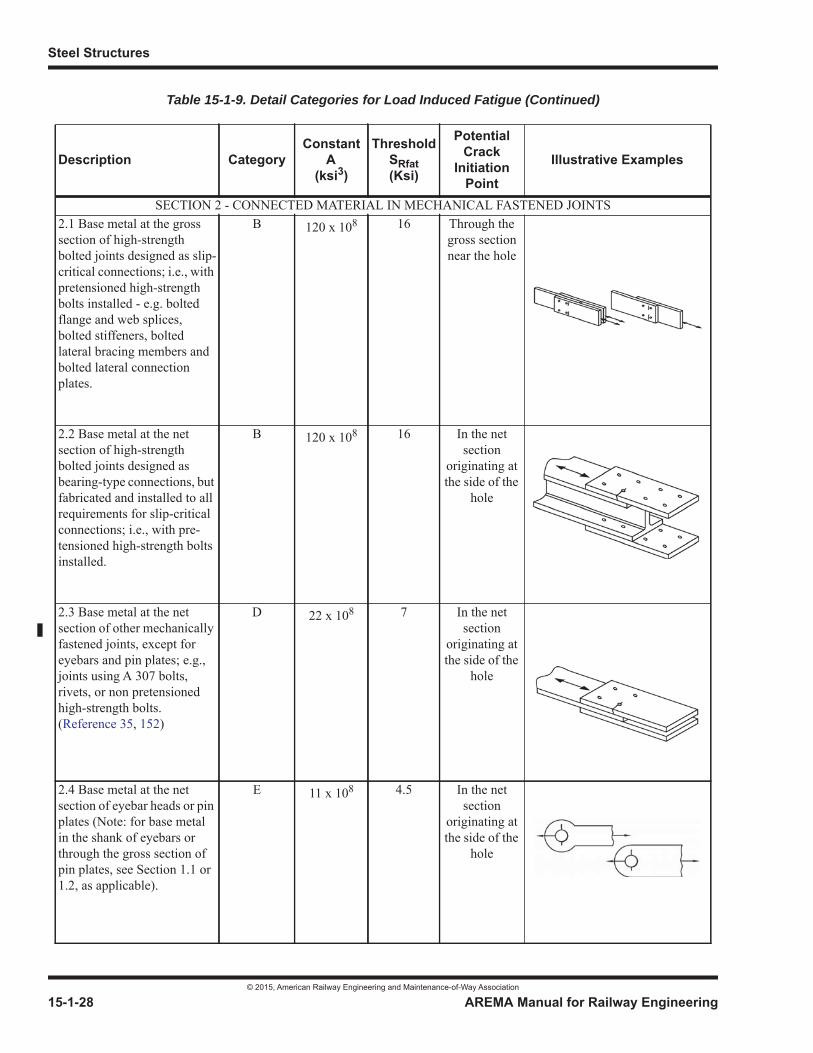
Steel Structures
© 2015, American Railway Engineering and Maintenance-of-Way Association
15-1-28 AREMA Manual for Railway Engineering
SECTION 2 - CONNECTED MATERIAL IN MECHANICAL FASTENED JOINTS2.1 Base metal at the gross section of high-strength bolted joints designed as slip-critical connections; i.e., with pretensioned high-strength bolts installed - e.g. bolted flange and web splices, bolted stiffeners, bolted lateral bracing members and bolted lateral connection plates.
B 120 x 108 16 Through the gross section near the hole
2.2 Base metal at the net section of high-strength bolted joints designed as bearing-type connections, but fabricated and installed to all requirements for slip-critical connections; i.e., with pre-tensioned high-strength bolts installed.
B 120 x 108 16 In the net section
originating at the side of the
hole
2.3 Base metal at the net section of other mechanically fastened joints, except for eyebars and pin plates; e.g., joints using A 307 bolts, rivets, or non pretensioned high-strength bolts. (Reference 35, 152)
D 22 x 108 7 In the net section
originating at the side of the
hole
2.4 Base metal at the net section of eyebar heads or pin plates (Note: for base metal in the shank of eyebars or through the gross section of pin plates, see Section 1.1 or 1.2, as applicable).
E 11 x 108 4.5 In the net section
originating at the side of the
hole
Table 15-1-9. Detail Categories for Load Induced Fatigue (Continued)
Description CategoryConstant
A(ksi3)
ThresholdSRfat(Ksi)
PotentialCrack
InitiationPoint
Illustrative Examples
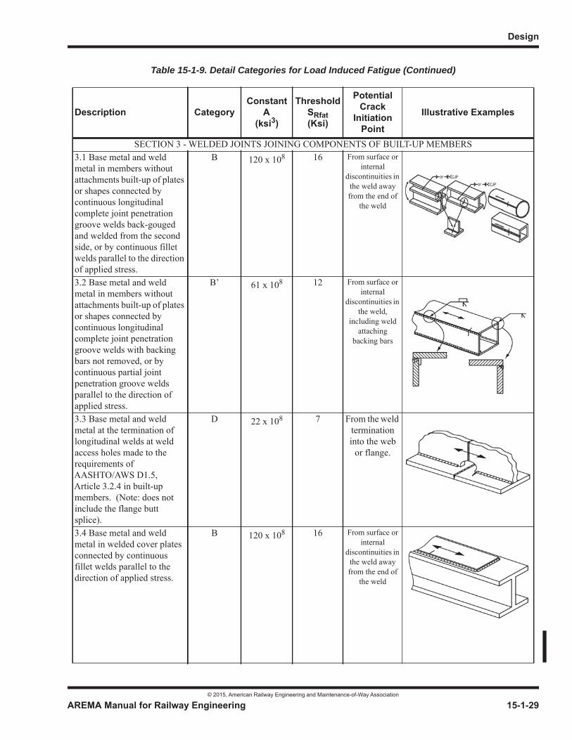
Design
© 2015, American Railway Engineering and Maintenance-of-Way Association
AREMA Manual for Railway Engineering 15-1-29
1
3
4
SECTION 3 - WELDED JOINTS JOINING COMPONENTS OF BUILT-UP MEMBERS3.1 Base metal and weld metal in members without attachments built-up of plates or shapes connected by continuous longitudinal complete joint penetration groove welds back-gouged and welded from the second side, or by continuous fillet welds parallel to the direction of applied stress.
B 120 x 108 16 From surface or internal
discontinuities in the weld away from the end of
the weld
3.2 Base metal and weld metal in members without attachments built-up of plates or shapes connected by continuous longitudinal complete joint penetration groove welds with backing bars not removed, or by continuous partial joint penetration groove welds parallel to the direction of applied stress.
B’ 61 x 108 12 From surface or internal
discontinuities in the weld,
including weld attaching
backing bars
3.3 Base metal and weld metal at the termination of longitudinal welds at weld access holes made to the requirements of AASHTO/AWS D1.5, Article 3.2.4 in built-up members. (Note: does not include the flange butt splice).
D 22 x 108 7 From the weld terminationinto the web
or flange.
3.4 Base metal and weld metal in welded cover plates connected by continuous fillet welds parallel to the direction of applied stress.
B 120 x 108 16 From surface or internal
discontinuities in the weld away from the end of
the weld
Table 15-1-9. Detail Categories for Load Induced Fatigue (Continued)
Description CategoryConstant
A(ksi3)
ThresholdSRfat(Ksi)
PotentialCrack
InitiationPoint
Illustrative Examples

Steel Structures
© 2015, American Railway Engineering and Maintenance-of-Way Association
15-1-30 AREMA Manual for Railway Engineering
SECTION 3 - WELDED JOINTS JOINING COMPONENTS OF BUILT-UP MEMBERS3.5 Base metal at the termination of partial length welded cover plates having square or tapered ends that are narrower than the flange, with or without welds across the ends, or cover plates that are wider than the flange with welds across the ends:
Flange thickness < 0.8 in.
Flange thickness > 0.8 in.
E
E’
11 x 108
3.9 x 10⁸
4.5
2.6
In the flange at the toe of the end weld
or in the flange at the
termination of the
longitudinalweld or in the
edge of the flange with wide cover
plates
3.6 Base metal at the termination of partial length welded cover plates with slip-critical bolted end connections designed to transfer the full strength of the cover plate.
B 120 x 108 16 In the flange at the
termination of the
longitudinalweld
3.7 Base metal at the termination of partial length welded cover plates that are wider than the flange and without welds across the ends.
E’ 3.9 x 10⁸ 2.6 In the edge of the flange at
the end of the cover plate
weld
Table 15-1-9. Detail Categories for Load Induced Fatigue (Continued)
Description CategoryConstant
A(ksi3)
ThresholdSRfat(Ksi)
PotentialCrack
InitiationPoint
Illustrative Examples
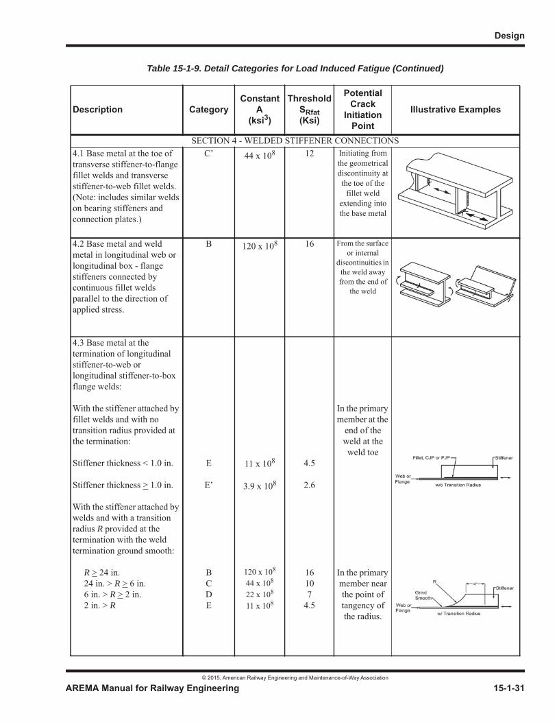
Design
© 2015, American Railway Engineering and Maintenance-of-Way Association
AREMA Manual for Railway Engineering 15-1-31
1
3
4
SECTION 4 - WELDED STIFFENER CONNECTIONS4.1 Base metal at the toe of transverse stiffener-to-flange fillet welds and transverse stiffener-to-web fillet welds. (Note: includes similar welds on bearing stiffeners and connection plates.)
C’ 44 x 108 12 Initiating from the geometrical discontinuity at the toe of the
fillet weld extending into the base metal
4.2 Base metal and weld metal in longitudinal web or longitudinal box - flange stiffeners connected by continuous fillet welds parallel to the direction of applied stress.
B 120 x 108 16 From the surface or internal
discontinuities in the weld away from the end of
the weld
4.3 Base metal at the termination of longitudinal stiffener-to-web or longitudinal stiffener-to-box flange welds:
With the stiffener attached by fillet welds and with no transition radius provided at the termination:
Stiffener thickness < 1.0 in.
Stiffener thickness > 1.0 in.
With the stiffener attached by welds and with a transition radius R provided at the termination with the weld termination ground smooth:
R > 24 in. 24 in. > R > 6 in. 6 in. > R > 2 in. 2 in. > R
E
E’
BCDE
11 x 108
3.9 x 10⁸
120 x 108
44 x 108
22 x 108
11 x 108
4.5
2.6
16107
4.5
In the primary member at the
end of the weld at the weld toe
In the primary member near the point of tangency of the radius.
Table 15-1-9. Detail Categories for Load Induced Fatigue (Continued)
Description CategoryConstant
A(ksi3)
ThresholdSRfat(Ksi)
PotentialCrack
InitiationPoint
Illustrative Examples

Steel Structures
© 2015, American Railway Engineering and Maintenance-of-Way Association
15-1-32 AREMA Manual for Railway Engineering
SECTION 5 - WELDED JOINTS TRANSVERSE TO THE DIRECTION OF PRIMARY STRESS5.1 Base metal and weld metal in or adjacent to complete joint penetration groove welded butt splices, with weld soundness established by NDT and with welds ground smooth and flush parallel to the direction of stress. Transitions in thickness or width shall be made on a slope no greater than 1:2.5.
Fy < 100 ksi
Fy > 100 ksi
B
B’
120 x 108
61 x 108
16
12
From internal discontinuities in the filler metal or along the fusion boundary or at the start of the
transition
5.2 Base metal and weld metal in or adjacent to complete joint penetration groove welded butt splices, with weld soundness established by NDT and with welds ground parallel to the direction of stress at transitions in width made on a radius of not less than 2 ft with the point of tangency at the end of the groove weld.
B 120 x 108 16 From internal discontinuities in the filler metal or
discontinuitiesalong the fusion
boundary
5.3 Base metal and weld metal in or adjacent to the toe of complete joint penetration groove welded T or corner joints, or in complete joint penetration groove welded butt splices, with or without transitions in thickness having slopes no greater than 1:2.5 when weld reinforcement is not removed. (Note: cracking in the flange of the ‘T’ may occur due to out-of-plane bending stresses induced by the stem.)
C 44 x 108 10 From the surface
discontinuity at the toe of the
weld extending into the base
metal along the fusion boundary
Table 15-1-9. Detail Categories for Load Induced Fatigue (Continued)
Description CategoryConstant
A(ksi3)
ThresholdSRfat(Ksi)
PotentialCrack
InitiationPoint
Illustrative Examples
w
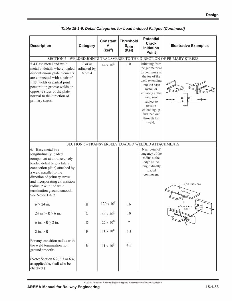
Design
© 2015, American Railway Engineering and Maintenance-of-Way Association
AREMA Manual for Railway Engineering 15-1-33
1
3
4
SECTION 5 - WELDED JOINTS TRANSVERSE TO THE DIRECTION OF PRIMARY STRESS5.4 Base metal and weld metal at details where loaded discontinuous plate elements are connected with a pair of fillet welds or partial joint penetration groove welds on opposite sides of the plate normal to the direction of primary stress.
C or as adjusted by
Note 4
44 x 108 10 Initiating from the geometrical discontinuity at the toe of the
weld extending into the base
metal, or initiating at the
weld root subject to tension
extending up and then out through the
weld.
SECTION 6 - TRANSVERSELY LOADED WELDED ATTACHMENTS6.1 Base metal in a longitudinally loaded component at a transversely loaded detail (e.g. a lateral connection plate) attached by a weld parallel to the direction of primary stress and incorporating a transition radius R with the weld termination ground smooth.See Notes 1 & 2.
R > 24 in.
24 in. > R > 6 in.
6 in. > R > 2 in.
2 in. > R
For any transition radius with the weld termination not ground smooth:
(Note: Section 6.2, 6.3 or 6.4, as applicable, shall also be checked.)
B
C
D
E
E
120 x 108
44 x 108
22 x 108
11 x 108
11 x 108
16
10
7
4.5
4.5
Near point of tangency of the
radius at the edge of the
longitudinallyloaded
component
Table 15-1-9. Detail Categories for Load Induced Fatigue (Continued)
Description CategoryConstant
A(ksi3)
ThresholdSRfat(Ksi)
PotentialCrack
InitiationPoint
Illustrative Examples
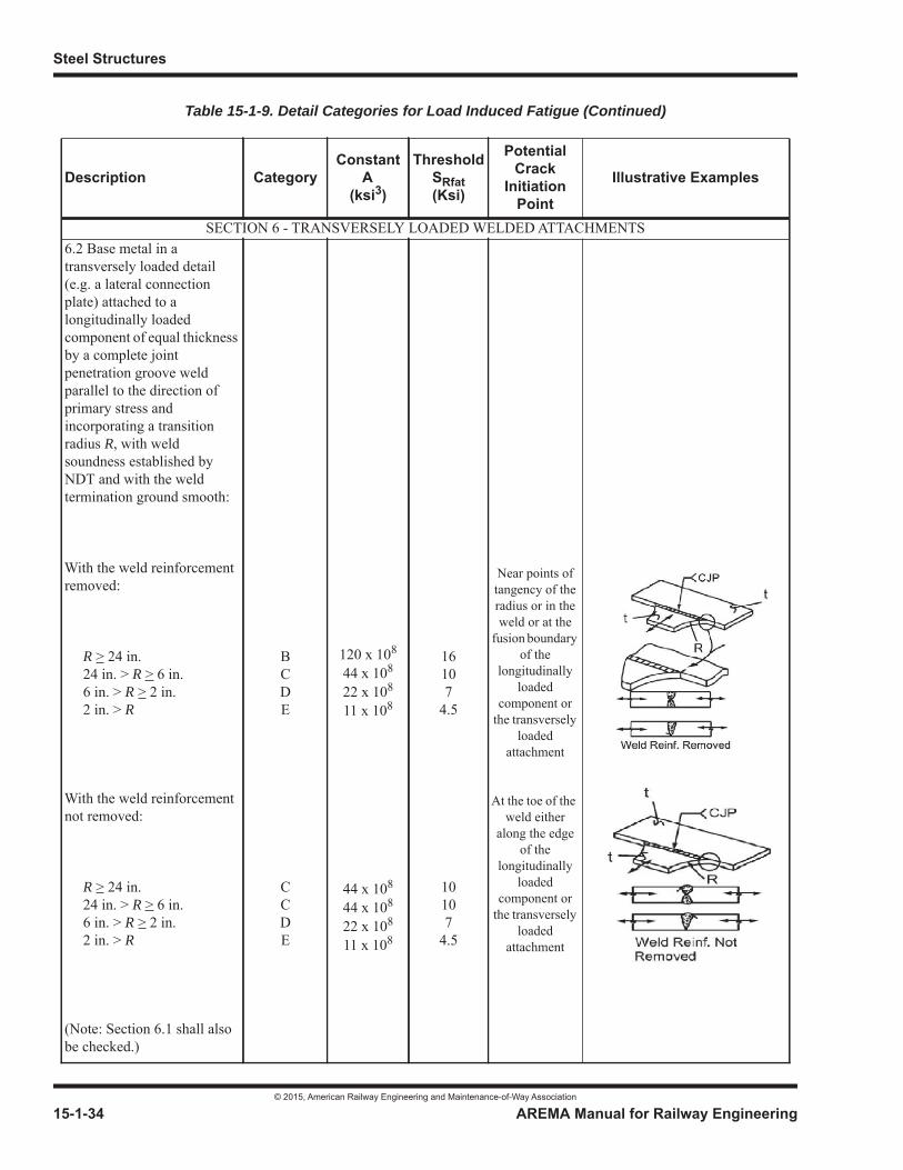
Steel Structures
© 2015, American Railway Engineering and Maintenance-of-Way Association
15-1-34 AREMA Manual for Railway Engineering
SECTION 6 - TRANSVERSELY LOADED WELDED ATTACHMENTS6.2 Base metal in a transversely loaded detail (e.g. a lateral connection plate) attached to a longitudinally loaded component of equal thickness by a complete joint penetration groove weld parallel to the direction of primary stress and incorporating a transition radius R, with weld soundness established by NDT and with the weld termination ground smooth:
With the weld reinforcement removed:
R > 24 in. 24 in. > R > 6 in. 6 in. > R > 2 in. 2 in. > R
With the weld reinforcement not removed:
R > 24 in. 24 in. > R > 6 in. 6 in. > R > 2 in. 2 in. > R
(Note: Section 6.1 shall also be checked.)
BCDE
CCDE
120 x 108
44 x 108
22 x 108
11 x 108
44 x 108
44 x 108
22 x 108
11 x 108
16107
4.5
10107
4.5
Near points of tangency of the radius or in the weld or at the
fusion boundary of the
longitudinallyloaded
component or the transversely
loadedattachment
At the toe of the weld either
along the edge of the
longitudinallyloaded
component or the transversely
loadedattachment
Table 15-1-9. Detail Categories for Load Induced Fatigue (Continued)
Description CategoryConstant
A(ksi3)
ThresholdSRfat(Ksi)
PotentialCrack
InitiationPoint
Illustrative Examples
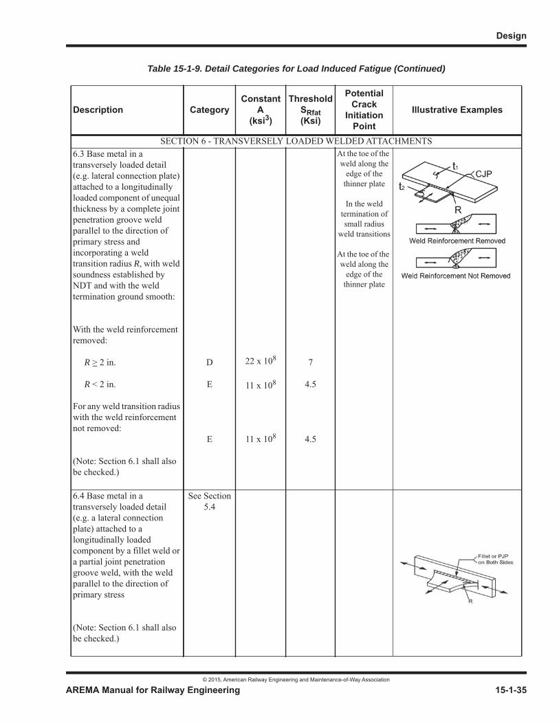
Design
© 2015, American Railway Engineering and Maintenance-of-Way Association
AREMA Manual for Railway Engineering 15-1-35
1
3
4
SECTION 6 - TRANSVERSELY LOADED WELDED ATTACHMENTS6.3 Base metal in a transversely loaded detail (e.g. lateral connection plate) attached to a longitudinally loaded component of unequal thickness by a complete joint penetration groove weld parallel to the direction of primary stress and incorporating a weld transition radius R, with weld soundness established by NDT and with the weld termination ground smooth:
With the weld reinforcement removed:
R > 2 in.
R < 2 in.
For any weld transition radius with the weld reinforcement not removed:
(Note: Section 6.1 shall also be checked.)
D
E
E
22 x 108
11 x 108
11 x 108
7
4.5
4.5
At the toe of the weld along the
edge of the thinner plate
In the weld termination of small radius
weld transitions
At the toe of the weld along the
edge of the thinner plate
6.4 Base metal in a transversely loaded detail (e.g. a lateral connection plate) attached to a longitudinally loaded component by a fillet weld or a partial joint penetration groove weld, with the weld parallel to the direction of primary stress
(Note: Section 6.1 shall also be checked.)
See Section 5.4
Table 15-1-9. Detail Categories for Load Induced Fatigue (Continued)
Description CategoryConstant
A(ksi3)
ThresholdSRfat(Ksi)
PotentialCrack
InitiationPoint
Illustrative Examples

Steel Structures
© 2015, American Railway Engineering and Maintenance-of-Way Association
15-1-36 AREMA Manual for Railway Engineering
SECTION 7 - LONGITUDINALLY LOADED WELDED ATTACHMENTS7.1 Base metal in a longitudinally loaded component at a detail with a length L in the direction of the primary stress and a thickness t attached by groove or fillet welds parallel or transverse to the direction of primary stress where the detail incorporates no transition radius:
See Notes 1 & 2.
L < 2 in. 2 in. < L < 12t or 4 in.
L > 12t or 4 in.t < 1.0 in.t > 1.0 in.
CD
EE’
44 x 108
22 x 108
11 x 108
3.9 x 10⁸
107
4.52.6
In the primary member at the
end of the weld at the weld toe
SECTION 8 - MISCELLANEOUS8.1 Base metal at stud-type shear connectors attached by fillet or automatic stud welding
C 44 x 108 10 At the toe of the weld in the
base metal
8.2 Non pretensioned high-strength bolts, common bolts, threaded anchor rods and hanger rods with cut, ground or rolled threads. Use the stress range acting on the tensile stress area due to live load plus prying action when applicable.
Finite Life
Infinite Life
E’
D
3.9 x 10⁸
N/A
N/A
7
At the root of the threads
extending into the tensile stress area
Table 15-1-9. Detail Categories for Load Induced Fatigue (Continued)
Description CategoryConstant
A(ksi3)
ThresholdSRfat(Ksi)
PotentialCrack
InitiationPoint
Illustrative Examples
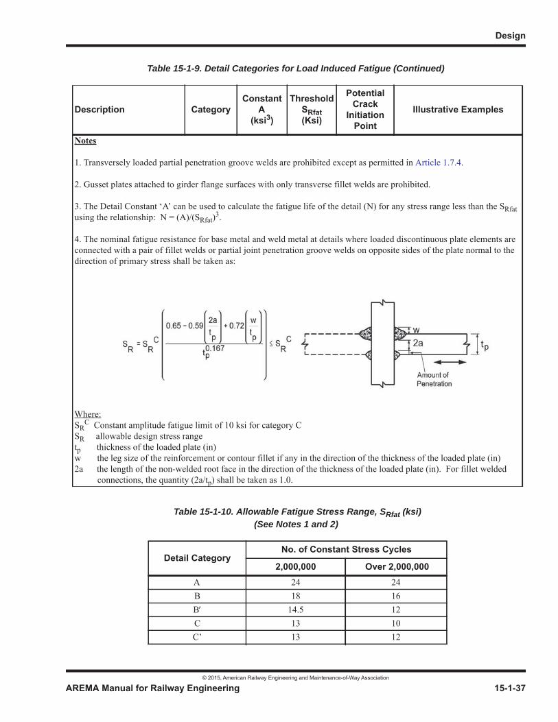
Design
© 2015, American Railway Engineering and Maintenance-of-Way Association
AREMA Manual for Railway Engineering 15-1-37
1
3
4
Notes
1. Transversely loaded partial penetration groove welds are prohibited except as permitted in Article 1.7.4.
2. Gusset plates attached to girder flange surfaces with only transverse fillet welds are prohibited.
3. The Detail Constant ‘A’ can be used to calculate the fatigue life of the detail (N) for any stress range less than the SRfatusing the relationship: N = (A)/(SRfat)3.
4. The nominal fatigue resistance for base metal and weld metal at details where loaded discontinuous plate elements are connected with a pair of fillet welds or partial joint penetration groove welds on opposite sides of the plate normal to the direction of primary stress shall be taken as:
Where:SR
C Constant amplitude fatigue limit of 10 ksi for category CSR allowable design stress rangetp thickness of the loaded plate (in)w the leg size of the reinforcement or contour fillet if any in the direction of the thickness of the loaded plate (in)2a the length of the non-welded root face in the direction of the thickness of the loaded plate (in). For fillet welded connections, the quantity (2a/tp) shall be taken as 1.0.
Table 15-1-10. Allowable Fatigue Stress Range, SRfat (ksi) (See Notes 1 and 2)
Detail CategoryNo. of Constant Stress Cycles
2,000,000 Over 2,000,000A 24 24B 18 16B 14.5 12C 13 10C’ 13 12
Table 15-1-9. Detail Categories for Load Induced Fatigue (Continued)
Description CategoryConstant
A(ksi3)
ThresholdSRfat(Ksi)
PotentialCrack
InitiationPoint
Illustrative Examples
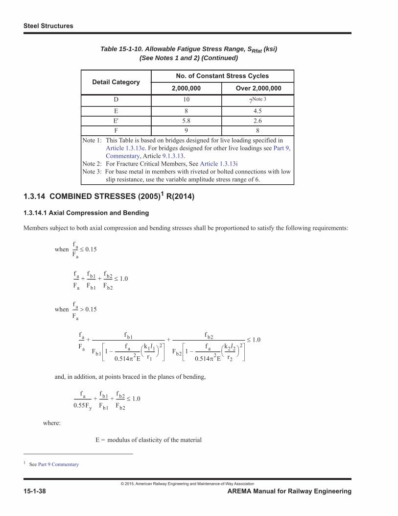
Steel Structures
© 2015, American Railway Engineering and Maintenance-of-Way Association
15-1-38 AREMA Manual for Railway Engineering
1.3.14 COMBINED STRESSES (2005)1 R(2014)
1.3.14.1 Axial Compression and Bending
Members subject to both axial compression and bending stresses shall be proportioned to satisfy the following requirements:
when
when
and, in addition, at points braced in the planes of bending,
where:
D 10 7Note 3
E 8 4.5E 5.8 2.6F 9 8
Note 1: This Table is based on bridges designed for live loading specified in Article 1.3.13e. For bridges designed for other live loadings see Part 9, Commentary, Article 9.1.3.13.
Note 2: For Fracture Critical Members, See Article 1.3.13iNote 3: For base metal in members with riveted or bolted connections with low
slip resistance, use the variable amplitude stress range of 6.
1 See Part 9 Commentary
E = modulus of elasticity of the material
Table 15-1-10. Allowable Fatigue Stress Range, SRfat (ksi) (See Notes 1 and 2) (Continued)
Detail CategoryNo. of Constant Stress Cycles
2,000,000 Over 2,000,000
f aFa----- 0.15
f a
Fa
-----f b1
Fb1
--------f b2
Fb2
-------- 1.0+ +
f a
Fa
----- 0.15
f a
Fa
-----f b1
Fb1 1f a
0.514 2E-----------------------
k1l1r1
----------2
–
-------------------------------------------------------------------f b2
Fb2 1f a
0.514 2E-----------------------
k2l2r2
----------2
–
------------------------------------------------------------------- 1.0+ +
f a
0.55Fy
----------------f b1
Fb1
--------f b2
Fb2
-------- 1.0+ +
Design
© 2015, American Railway Engineering and Maintenance-of-Way Association
AREMA Manual for Railway Engineering 15-1-39
1
3
4
1.3.14.2 Axial Tension and Bending
Members subject to both axial tension and bending stresses shall be proportioned so that the total of the axial tensile stress andthe bending tensile stresses about both axes shall not exceed the values indicated in Table 15-1-11. The compressive stress, if any, resulting from combining the compressive stress with respect to either axis and the minimum simultaneous axial tension stress shall not exceed the value indicated by Table 15-1-11 for compression in the extreme fibers of flexural members.
1.3.14.3 Allowable Stresses for Combinations of Loads or Wind Forces Only
a. Members subject to stresses resulting from dead load, live load, impact load and centrifugal force shall be designed so that the maximum stresses do not exceed the basic allowable stresses of Section 1.4, Basic Allowable Stresses, and the stress range does not exceed the allowable fatigue stress range of Article 1.3.13.
b. The basic allowable stresses of Section 1.4, Basic Allowable Stresses shall be used in the proportioning of members subject to stresses resulting from wind forces only, as specified in Article 1.3.8.
c. Members, except floorbeam hangers, which are subject to stresses resulting from longitudinal forces and/or lateral forces other than centrifugal force may be proportioned for stresses 25% greater than those permitted by paragraph a.However, the section of the member shall not be less than that required to meet the provisions of paragraph a or paragraph b alone.
d. Increase in allowable stress permitted by paragraph c shall not be applied to allowable stress in high-strength bolts.
1.3.15 SECONDARY STRESSES (1994)1 R(2014)
The design and details shall be such that secondary stresses will be as small as practicable. Secondary stresses due to truss distortion usually need not be considered in any member the width of which, measured parallel to the plane of distortion, is less than one-tenth of its length. If the secondary stress exceeds 4,000 psi for tension members and 3,000 psi for compression members, the excess shall be treated as a primary stress.
1.3.16 PROPORTIONING OF TRUSS WEB MEMBERS (2004)2 R(2014)
Web members and their connections shall be proportioned such that an increase in the specified live load that will increase thetotal stress in the most highly stressed chord by one-third will produce total stresses in the web members and their connectionsnot greater than one and one-third times the allowable stresses.
Fy = yield point of the material as specified in Table 15-1-1
Fa = axial stress that would be permitted if axial force alone existed
Fb1 and Fb2 = compressive bending stress about axes 1–1 and 2–2, respectively, that would be permitted if bending alone existed
fa = calculated axial stress
fb1 and fb2 = calculated compressive bending stress about axes 1–1 and 2–2, respectively, at the point under consideration
= ratios of the effective length in inches to the radius of gyration in inches, of the compression member about axes 1–1 and 2–2, respectively
1 See Part 9 Commentary2 See Part 9 Commentary
k1l1r1
----------and k2l2r2
----------
Steel Structures
© 2015, American Railway Engineering and Maintenance-of-Way Association
15-1-40 AREMA Manual for Railway Engineering
1.3.17 EARTHQUAKE FORCES (1994) R(2014)
Members and connections subjected to earthquake forces shall be designed in accordance with the requirements of Chapter 9, Seismic Design for Railway Structures.
SECTION 1.4 BASIC ALLOWABLE STRESSES
The basic allowable stresses to be used in proportioning the parts of a bridge shall be as specified below. When the allowable stress is expressed in terms of Fy, Fy = yield point of the material as specified in Table 15-1-1. Fu = lowest ultimate strength of the material as specified in Table 15-1-1.
1.4.1 STRUCTURAL STEEL, RIVETS, BOLTS AND PINS (2011)1 R(2014)
See Table 15-1-11.
1 See Part 9 Commentary
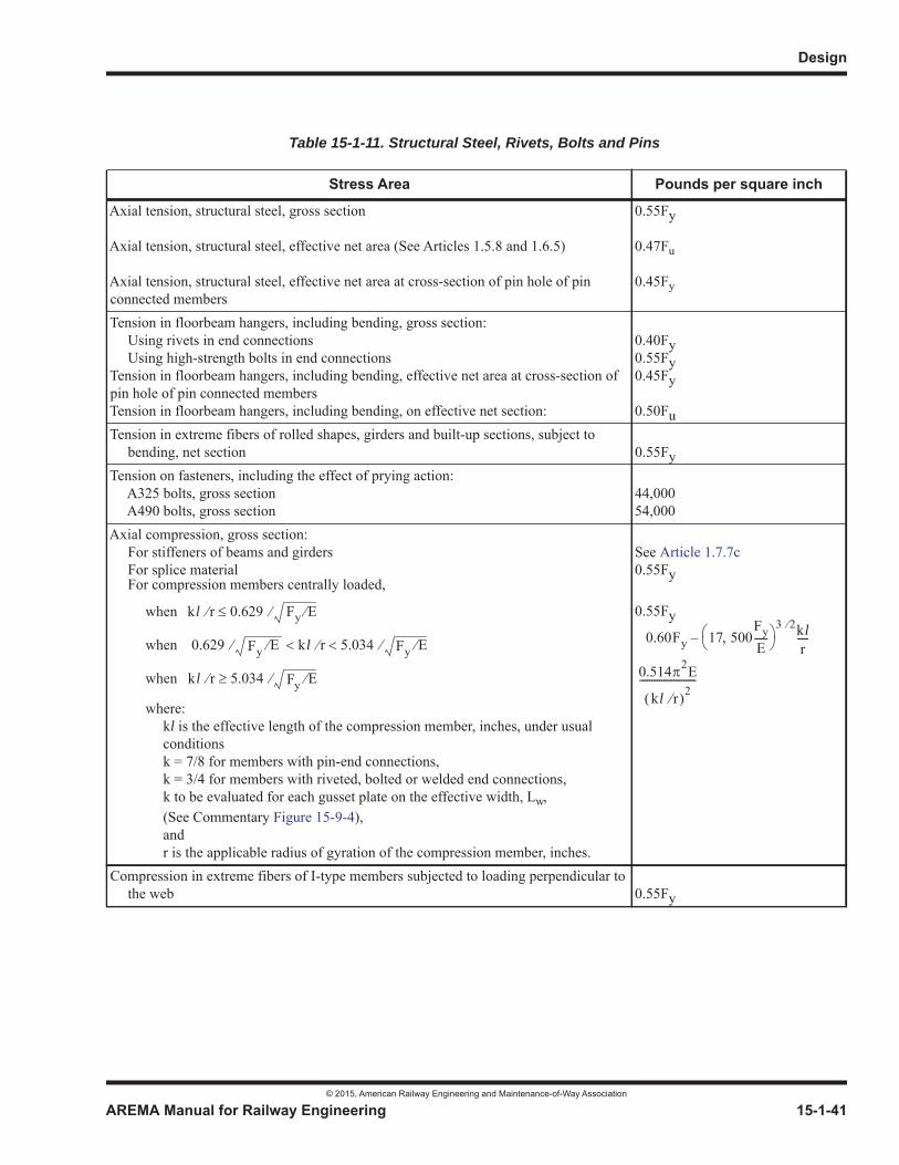
Design
© 2015, American Railway Engineering and Maintenance-of-Way Association
AREMA Manual for Railway Engineering 15-1-41
1
3
4
Table 15-1-11. Structural Steel, Rivets, Bolts and Pins
Stress Area Pounds per square inch
Axial tension, structural steel, gross section
Axial tension, structural steel, effective net area (See Articles 1.5.8 and 1.6.5)
Axial tension, structural steel, effective net area at cross-section of pin hole of pin connected members
0.55Fy
0.47Fu
0.45Fy
Tension in floorbeam hangers, including bending, gross section:Using rivets in end connectionsUsing high-strength bolts in end connections
Tension in floorbeam hangers, including bending, effective net area at cross-section of pin hole of pin connected membersTension in floorbeam hangers, including bending, on effective net section:
0.40Fy0.55Fy0.45Fy
0.50FuTension in extreme fibers of rolled shapes, girders and built-up sections, subject to
bending, net section 0.55FyTension on fasteners, including the effect of prying action:
A325 bolts, gross sectionA490 bolts, gross section
44,00054,000
Axial compression, gross section:For stiffeners of beams and girdersFor splice material
See Article 1.7.7c0.55Fy
For compression members centrally loaded,
when
when
when
0.55Fy
where:kl is the effective length of the compression member, inches, under usual conditionsk = 7/8 for members with pin-end connections, k = 3/4 for members with riveted, bolted or welded end connections, k to be evaluated for each gusset plate on the effective width, Lw,(See Commentary Figure 15-9-4),andr is the applicable radius of gyration of the compression member, inches.
Compression in extreme fibers of I-type members subjected to loading perpendicular to the web 0.55Fy
kl r 0.629 Fy E
0.629 Fy E kl r 5.034 Fy E
kl r 5.034 Fy E
0.60Fy 17 500FyE-----
3 2klr-----–
0.514 2E
kl r 2-----------------------
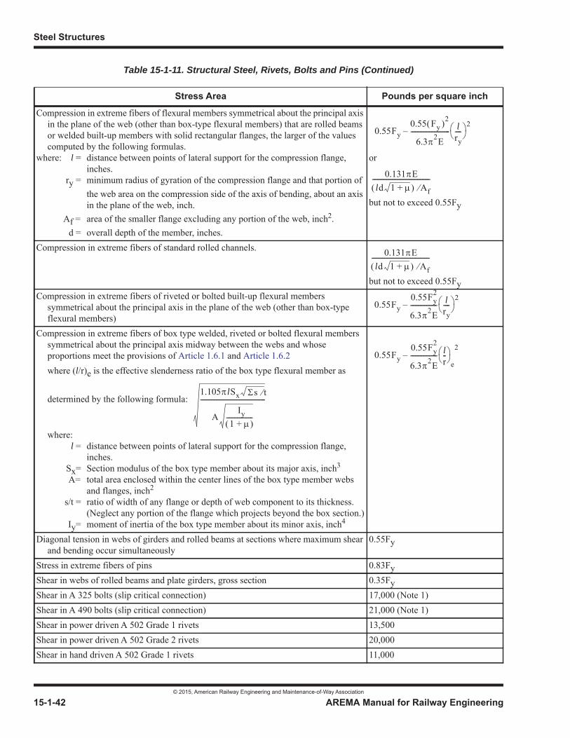
Steel Structures
© 2015, American Railway Engineering and Maintenance-of-Way Association
15-1-42 AREMA Manual for Railway Engineering
Compression in extreme fibers of flexural members symmetrical about the principal axis in the plane of the web (other than box-type flexural members) that are rolled beams or welded built-up members with solid rectangular flanges, the larger of the values computed by the following formulas.
where: l = distance between points of lateral support for the compression flange, inches.
ry = minimum radius of gyration of the compression flange and that portion of the web area on the compression side of the axis of bending, about an axis in the plane of the web, inch.
Af = area of the smaller flange excluding any portion of the web, inch2.d = overall depth of the member, inches.
or
but not to exceed 0.55Fy
Compression in extreme fibers of standard rolled channels.
but not to exceed 0.55FyCompression in extreme fibers of riveted or bolted built-up flexural members
symmetrical about the principal axis in the plane of the web (other than box-type flexural members)
Compression in extreme fibers of box type welded, riveted or bolted flexural members symmetrical about the principal axis midway between the webs and whose proportions meet the provisions of Article 1.6.1 and Article 1.6.2where (l/r)e is the effective slenderness ratio of the box type flexural member as
determined by the following formula:
where:l = distance between points of lateral support for the compression flange,
inches.Sx= Section modulus of the box type member about its major axis, inch3
A= total area enclosed within the center lines of the box type member webs and flanges, inch2
s/t = ratio of width of any flange or depth of web component to its thickness. (Neglect any portion of the flange which projects beyond the box section.)
Iy= moment of inertia of the box type member about its minor axis, inch4
Diagonal tension in webs of girders and rolled beams at sections where maximum shear and bending occur simultaneously
0.55Fy
Stress in extreme fibers of pins 0.83FyShear in webs of rolled beams and plate girders, gross section 0.35FyShear in A 325 bolts (slip critical connection) 17,000 (Note 1)Shear in A 490 bolts (slip critical connection) 21,000 (Note 1)Shear in power driven A 502 Grade 1 rivets 13,500Shear in power driven A 502 Grade 2 rivets 20,000Shear in hand driven A 502 Grade 1 rivets 11,000
Table 15-1-11. Structural Steel, Rivets, Bolts and Pins (Continued)
Stress Area Pounds per square inch
0.55Fy0.55 Fy
2
6.3 2E------------------------- l
ry----
2–
0.131 Eld 1 + Af
-------------------------------------
0.131 Eld 1 + Af
-------------------------------------
0.55Fy0.55Fy
2
6.3 2E----------------- l
ry----
2–
0.55Fy0.55Fy
2
6.3 2E----------------- l
r--
e
2–
1.105 lSx s t
AIy
1 +-----------------
------------------------------------------

Design
© 2015, American Railway Engineering and Maintenance-of-Way Association
AREMA Manual for Railway Engineering 15-1-43
1
3
4
Shear in pins 0.42FyBearing on power driven A 502 Grade 1 rivets,
in single shearin double shear
27,00036,000
Bearing on power driven A 502 Grade 2 rivets, on material with a yield point of Fyin single shear
but not to exceedin double shear
but not to exceed(Rivets driven by pneumatically or electrically operated hammers are considered power driven.)
0.75Fy40,000Fy50,000
Bearing on hand driven A 502 Grade 1 rivets 20,000Bearing on pinsFy = yield point of the material on which the pin bears, or of the pin material, as specified in Table 15-1-1 whichever is less
0.75Fy
Bearing on A 325 and A 490 boltswhere:
L = Distance, inches, measured in the line of force from the center line of a bolt to the nearest edge of an adjacent bolt or to the end of the connected part toward which the force is directed.
d = Diameter of bolts, inch.Fu = lowest specified minimum tensile strength of the connected part, psi, as
specified in Table 15-1-1.
(Note 2)
(whichever is smaller)
Bearing on milled stiffeners and other steel parts in contact 0.83FyBolts Subjected to Combined Tension and Shearwhere:
Fv = Allowable shear stress, reduced due to combined stress, psiSa = Allowable shear stress, when loaded in shear only, psift = Average tensile stress due to direct load, psi
Ab = Nominal bolt area, inch2
Tb = Minimum tension of installed bolts, Table 15-1-12, lb
Fv Sa (1 – ftAb/Tb)
Note 1: Applicable for surfaces with clean mill scale free of oil, paint, lacquer or other coatings and loose oxide for standardsize holes as specified in Part 3, Fabrication, Article 3.2.5. Where the Engineer has specified special treatment of surfaces or other than standard holes in a slip-critical connection, the allowable stresses in Table 15-1-11a. may be used if approved by the Engineer.
Note 2: For single bolt in line of force or connected materials with long slotted holes, 1.0 Fu is the limit. A value of allowable bearing pressure Fp on the connected material at a bolt greater than permitted can be justified provided deformation around the bolt hole is not a design consideration and adequate pitch and end distance L are provided according to
Table 15-1-11. Structural Steel, Rivets, Bolts and Pins (Continued)
Stress Area Pounds per square inch
LFu
2d---------or 1.2Fu
Fp LFu 2d 1.5Fu=
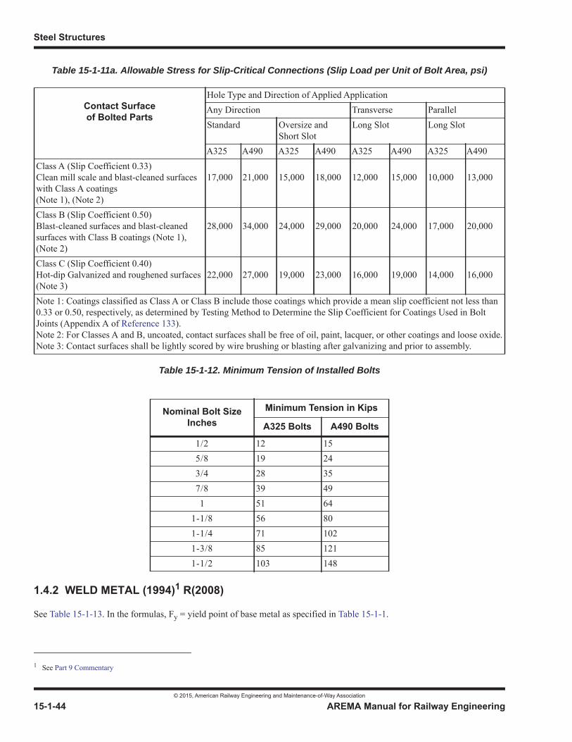
Steel Structures
© 2015, American Railway Engineering and Maintenance-of-Way Association
15-1-44 AREMA Manual for Railway Engineering
Table 15-1-11a. Allowable Stress for Slip-Critical Connections (Slip Load per Unit of Bolt Area, psi)
Table 15-1-12. Minimum Tension of Installed Bolts
1.4.2 WELD METAL (1994)1 R(2008)
See Table 15-1-13. In the formulas, Fy = yield point of base metal as specified in Table 15-1-1.
Contact Surfaceof Bolted Parts
Hole Type and Direction of Applied ApplicationAny Direction Transverse ParallelStandard Oversize and
Short SlotLong Slot Long Slot
A325 A490 A325 A490 A325 A490 A325 A490Class A (Slip Coefficient 0.33)Clean mill scale and blast-cleaned surfaces with Class A coatings(Note 1), (Note 2)
17,000 21,000 15,000 18,000 12,000 15,000 10,000 13,000
Class B (Slip Coefficient 0.50)Blast-cleaned surfaces and blast-cleaned surfaces with Class B coatings (Note 1), (Note 2)
28,000 34,000 24,000 29,000 20,000 24,000 17,000 20,000
Class C (Slip Coefficient 0.40)Hot-dip Galvanized and roughened surfaces (Note 3)
22,000 27,000 19,000 23,000 16,000 19,000 14,000 16,000
Note 1: Coatings classified as Class A or Class B include those coatings which provide a mean slip coefficient not less than 0.33 or 0.50, respectively, as determined by Testing Method to Determine the Slip Coefficient for Coatings Used in Bolt Joints (Appendix A of Reference 133).Note 2: For Classes A and B, uncoated, contact surfaces shall be free of oil, paint, lacquer, or other coatings and loose oxide.Note 3: Contact surfaces shall be lightly scored by wire brushing or blasting after galvanizing and prior to assembly.
Nominal Bolt Size Inches
Minimum Tension in Kips
A325 Bolts A490 Bolts
1/2 12 155/8 19 243/4 28 357/8 39 491 51 64
1-1/8 56 801-1/4 71 1021-3/8 85 1211-1/2 103 148
1 See Part 9 Commentary
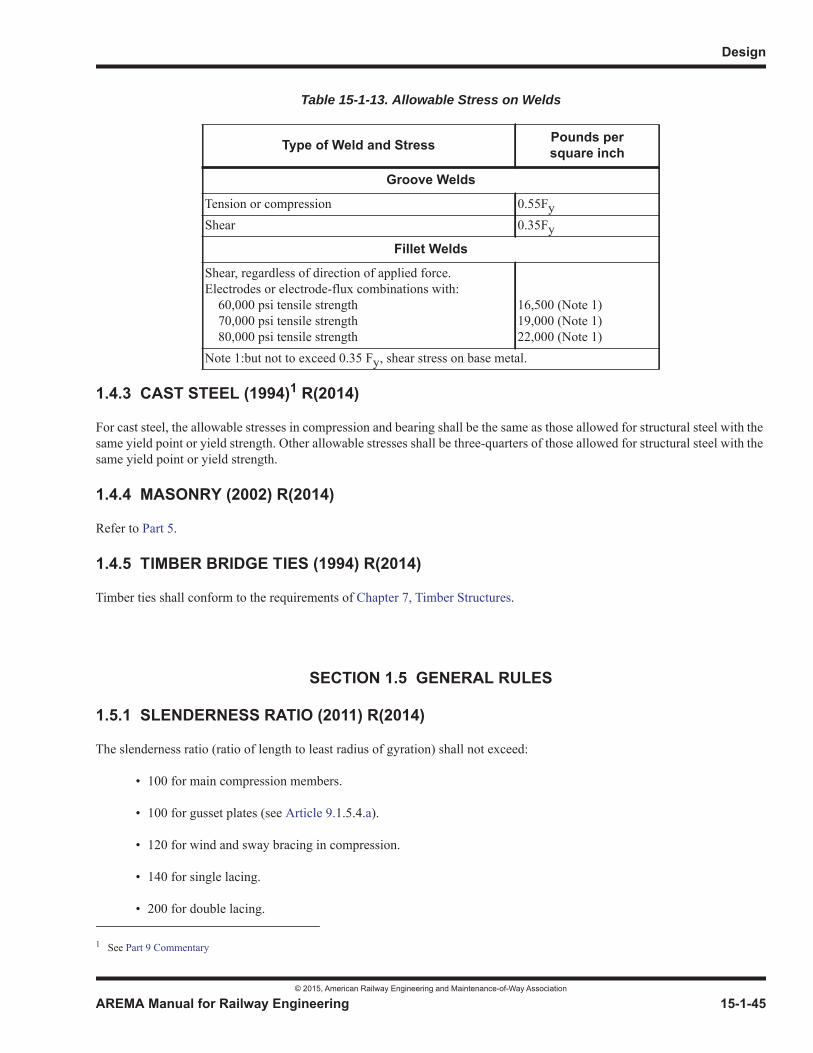
Design
© 2015, American Railway Engineering and Maintenance-of-Way Association
AREMA Manual for Railway Engineering 15-1-45
1
3
4
1.4.3 CAST STEEL (1994)1 R(2014)
For cast steel, the allowable stresses in compression and bearing shall be the same as those allowed for structural steel with thesame yield point or yield strength. Other allowable stresses shall be three-quarters of those allowed for structural steel with the same yield point or yield strength.
1.4.4 MASONRY (2002) R(2014)
Refer to Part 5.
1.4.5 TIMBER BRIDGE TIES (1994) R(2014)
Timber ties shall conform to the requirements of Chapter 7, Timber Structures.
SECTION 1.5 GENERAL RULES
1.5.1 SLENDERNESS RATIO (2011) R(2014)
The slenderness ratio (ratio of length to least radius of gyration) shall not exceed:
• 100 for main compression members.
• 100 for gusset plates (see Article 9.1.5.4.a).
• 120 for wind and sway bracing in compression.
• 140 for single lacing.
• 200 for double lacing.
Table 15-1-13. Allowable Stress on Welds
Type of Weld and Stress Pounds persquare inch
Groove Welds
Tension or compression 0.55FyShear 0.35Fy
Fillet Welds
Shear, regardless of direction of applied force.Electrodes or electrode-flux combinations with: 60,000 psi tensile strength 70,000 psi tensile strength 80,000 psi tensile strength
16,500 (Note 1)19,000 (Note 1)22,000 (Note 1)
Note 1:but not to exceed 0.35 Fy, shear stress on base metal.
1 See Part 9 Commentary
Steel Structures
© 2015, American Railway Engineering and Maintenance-of-Way Association
15-1-46 AREMA Manual for Railway Engineering
• 200 for tension members.
1.5.2 EFFECTIVE DIAMETER OF FASTENERS (1993) R(2014)
The nominal diameter of fasteners shall be considered the effective diameter.
1.5.3 EFFECTIVE BEARING AREA OF BOLTS, RIVETS AND PINS (1993) R(2014)
The effective bearing area of bolts, rivets and pins shall be the diameter multiplied by the length in bearing: except that forcountersunk bolts and rivets, one-half the depth of the countersink shall be deducted from the length.
1.5.4 THICKNESS OF MATERIAL (2011)1 R(2014)
a. Metal, except for fillers, shall not be less than 3/8 inch thick. Parts subject to marked corrosive influences shall be of greater thickness than otherwise or else protected against such influences.
b. The thickness of gusset plates connecting the chords and web members of a truss shall be proportioned for the force to be transferred but not less than 1/2 inch.
c. If the unsupported length of an edge of a gusset plate exceeds its thickness times
1.5.5 ACCESSIBILITY OF PARTS (1993) R(2014)
Details shall be such that all exposed parts will be accessible for inspection, cleaning and painting. Preferably not less than 18 inches clear shall be provided between the flanges of parallel lines of beams having depths in excess of 38 inches.
1.5.6 DRAINAGE OF POCKETS (1993) R(2014)
Pockets or depressions that would hold water either shall have effective drain holes or shall be filled or caulked with an approved permanent-type waterproof caulking compound. Structural members shall not be caulked by welding except as approved by the Engineer.
1.5.7 ECCENTRIC CONNECTIONS (1993) R(2014)
a. Eccentricity between intersecting parts and between gravity axes of members intersecting at a panel point shall be avoided, insofar as practicable. If eccentric connections are unavoidable, adequate provision shall be made for the bending stresses resulting from the eccentricity.
b. For members having symmetrical cross sections, the connecting welds or fasteners shall be arranged symmetrically about the axis of the member, or proper allowance shall be made for unsymmetrical distribution of stresses.
1 See Part 9 Commentary
2.06 EFy----- the edge shall be stiffened.
Design
© 2015, American Railway Engineering and Maintenance-of-Way Association
AREMA Manual for Railway Engineering 15-1-47
1
3
4
1.5.8 NET SECTION (2005)1 R(2014)
a. The net section of a riveted or bolted tension member, An, is the sum of the net sections of its component parts. The net section of a part is the product of the thickness of the part multiplied by its least net width.
b. The net width for any chain of holes extending progressively across the part shall be obtained by deducting from the gross width the sum of the diameters of all the holes in the chain and adding, for each space in the chain, the quantity:
where:
The net section of the part is obtained from that chain which gives the least net width, except that the net width shall in no case be considered as more than 85% of the corresponding gross width.
c. For angles, the gross width shall be the sum of the widths of the legs less the thickness. The gage for holes in opposite legs shall be the sum of the gages, measured from back of angle, less the thickness.
d. For splice material, the effective thickness shall be only that part of the material which has been developed by rivets or bolts.
e. The diameter of the hole shall be taken as 1/8 inch greater than the nominal diameter of the rivet or bolt.
1.5.9 CONNECTIONS AND SPLICES (2014)2
a. Connections and splices, except as used in paragraph d below for milled splices in compression, shall be in accordance with the following provisions:
(1) Splices of main members shall have a strength not less than the capacity of the member and shall satisfy the requirements of Article 1.7.5 and Article 1.7.6.
End connections of main members receiving load from the combined effect of floor system and truss action shall have a strength not less than the capacity of the member. End connections of members carrying direct load from one floorbeam only shall be proportioned for at least 1.25 times their computed reactions.
End connections of simply supported floorbeams, stringers, and other beams and girders acting and framed similarly, shall be proportioned for at least 1.25 times their computed shear. Alternatively, these connections shall be proportioned for the combined effect of moment and shear.
(2) End connections of secondary and bracing members shall have a strength of the lesser of the strength of the member based on the allowable unit stress or 1.5 times the maximum computed stress.
The requirement of Article 1.3.13 shall be satisfied. Bracing members used only as ties or struts to reduce the unsupported length of a member to which they connect need not be connected for more than the force specified in Article 1.11.6.
1 See Part 9 Commentary
s = pitch of the two successive holes in the chain, in the direction of tensile stressg = gage of the same holes, in the transverse direction
2 See Part 9 Commentary
s2
4g------
Steel Structures
© 2015, American Railway Engineering and Maintenance-of-Way Association
15-1-48 AREMA Manual for Railway Engineering
b. All groove welds shall have full penetration, and shall satisfy the requirements of Article 1.3.13.
c. Bolted or riveted connections shall have not less than three fasteners per plane of connection or equivalent strength in welding. The weld shall preferably be a fillet weld and be parallel and symmetrical to the direction of force.
d. Members subject to compression only, if faced for bearing, shall be spliced on 4 sides sufficiently to hold the abutting parts accurately and securely in place. The splice shall be as near a panel point as practicable and shall be designed to transmit at least one-half of the force through the splice material. Where such members are in full milled bearing on base plates, there shall be sufficient bolted or riveted connecting material, or welding, to hold all parts securely in place.
e. Block shear shall be evaluated at beam end connections where the top flange is coped, at the end connections of tension members, in connections utilizing gusset plates and all other connections where failure by block shear is a concern.The allowable block shear rupture strength shall be the lesser of:
(1) 0.30FuAnv + 0.50UbsFuAnt
or
(2) 0.30FyAgv + 0.50UbsFuAnt
where:
Agv = gross area subject to shear, in2
Anv = net area subject to shear, in2
Ant = net area subject to tension, in2
Ubs = 1.0 when the tension stress is uniformUbs = 0.5 when the tension stress is non-uniform
1.5.10 FIELD CONNECTIONS (1994)1 R(2014)
Field connections, including splices, shall be made using rivets or high-strength bolts except that field welding may be used for minor connections not subject to live load force, and for joining sections of deck plates, etc., which do not function as partof the load carrying structure. Otherwise, welding shall not be used for field connections.
1.5.11 DEVELOPMENT OF FILLERS (2015)2
a. For high-strength bolted construction, no additional bolts are necessary for the development of fillers unless required to meet the seismic requirement of Chapter 9 (See Commentary).
b. For riveted construction, when rivets subject to force pass through fillers, the fillers shall be extended beyond the connected member and the extension secured by enough rivets to distribute the total force to the member uniformly over the combined sections of the member and the fillers, except that fillers less than 1/4 inch thick shall not be extended beyond the splicing material, and additional rivets are not required.
c. For riveted construction, eccentricity must be considered on short, thick fillers.
1 See Part 9 Commentary2 See Part 9 Commentary
Design
© 2015, American Railway Engineering and Maintenance-of-Way Association
AREMA Manual for Railway Engineering 15-1-49
1
3
4
1.5.12 COMBINATIONS OF DISSIMILAR TYPES OF CONNECTIONS (1993)1 R(2014)
a. Rivets and high-strength bolts in the same connection plane may be considered as sharing the force. When such a connection plane is subjected to fatigue conditions, the requirements of Article 1.3.13 applicable to rivets shall be satisfied for both types of fasteners.
b. Welds acting in the same connection with rivets and/or bolts shall be proportioned to carry the entire force.
1.5.13 SEALING (1993)2 R(2014)
a. Where two or more plates or shapes are in contact, provision shall be made for sealing their edges for protection against the entrance of moisture between them.
b. For riveted and bolted members, sealing shall be accomplished by limiting the spacing of the fasteners connecting component parts. The pitch on a single line adjacent to a free edge of an outside plate or shape shall not exceed 4 + 4t, where t is the thickness of the thinnest outside plate or shape in inches, nor 7 inches. Where there is a second line of fasteners uniformly staggered with those in the line adjacent to the free edge, at a gage, g, less than 1-1/2 + 4t inches, therefrom, the staggered pitch of the fasteners in the two lines shall not exceed 4 + 4t – 3/4 g inches, nor 7– 3/4 g inches, but need not be less than one-half the requirement for a single line.
c. For welded members, longitudinal sealing may be accomplished by the use of continuous welds at exposed edges of contact surfaces, of such dimensions and made by such procedure as will ensure weld soundness throughout.
1.5.14 CONNECTIONS OF COMPONENTS OF BUILT-UP MEMBERS (1993)3 R(2014)
a. Where two or more plates or shapes are in contact, they shall be connected adequately to make them act in unison.
b. For riveted and bolted members, stitch fasteners shall be used to make component parts of the member act in unison. The pitch of stitch fasteners in compression members on any single line shall not exceed 12t, where t is the thickness of the thinnest outside plate or shape, except that, if the fasteners on adjacent lines are staggered and the gage, g, between the line under consideration and the farther adjacent line is less than 24t, the staggered pitch in such two lines shall not exceed 12t, nor 15t – 3/8 g. The gage between adjacent lines of such stitch rivets shall not exceed 24t. At the ends of compression members, the pitch of stitch fasteners on any single line in the direction of stress shall not exceed 4 times the diameter of the fasteners for a distance equal to 1.5 times the width of the member. In tension members, the pitch of stitch fasteners shall not exceed twice that specified for compression members, and the gage shall not exceed that specified for compression members.
c. The requirements of Article 1.5.13 and this Article are not additive, but both must be satisfied by the detail used.
1.5.15 WELDED CLOSED BOX MEMBERS (1993) R(2014)
a. Absolute airtightness of box members is not required.
b. Box members shall be closed to the elements so as to inhibit access of water or moisture to the interior.
c. Crevices in areas where standing water may be drawn into the box member as a result of interior pressure changes shall be sealed with an approved permanent-type waterproof caulking compound; or, alternatively, such crevices may be sealed by welding if the details are approved by the Engineer.
1 See Part 9 Commentary2 See Part 9 Commentary3 See Part 9 Commentary
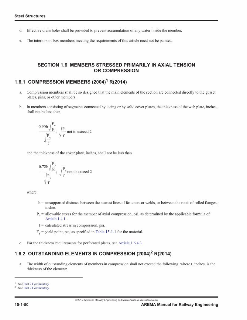
Steel Structures
© 2015, American Railway Engineering and Maintenance-of-Way Association
15-1-50 AREMA Manual for Railway Engineering
d. Effective drain holes shall be provided to prevent accumulation of any water inside the member.
e. The interiors of box members meeting the requirements of this article need not be painted.
SECTION 1.6 MEMBERS STRESSED PRIMARILY IN AXIAL TENSION OR COMPRESSION
1.6.1 COMPRESSION MEMBERS (2004)1 R(2014)
a. Compression members shall be so designed that the main elements of the section are connected directly to the gusset plates, pins, or other members.
b. In members consisting of segments connected by lacing or by solid cover plates, the thickness of the web plate, inches, shall not be less than
and the thickness of the cover plate, inches, shall not be less than
where:
c. For the thickness requirements for perforated plates, see Article 1.6.4.3.
1.6.2 OUTSTANDING ELEMENTS IN COMPRESSION (2004)2 R(2014)
a. The width of outstanding elements of members in compression shall not exceed the following, where t, inches, is the thickness of the element:
1 See Part 9 Commentary
b = unsupported distance between the nearest lines of fasteners or welds, or between the roots of rolled flanges, inches
Pc = allowable stress for the member of axial compression, psi, as determined by the applicable formula of Article 1.4.1.
f = calculated stress in compression, psi.Fy = yield point, psi, as specified in Table 15-1-1 for the material.
2 See Part 9 Commentary
0.90bFyE-----
Pc
f-----
------------------------; Pc
f----- not to exceed 2
0.72bFyE-----
Pc
f-----
------------------------; Pc
f----- not to exceed 2
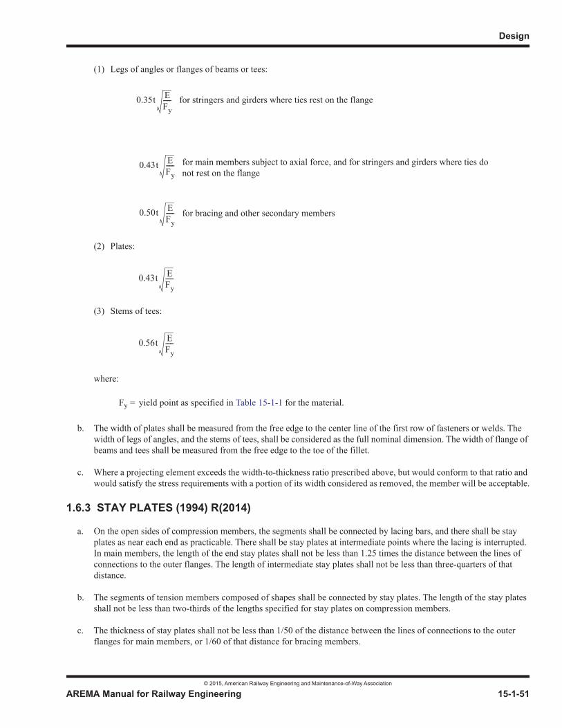
Design
© 2015, American Railway Engineering and Maintenance-of-Way Association
AREMA Manual for Railway Engineering 15-1-51
1
3
4
(1) Legs of angles or flanges of beams or tees:
for stringers and girders where ties rest on the flange
for bracing and other secondary members
(2) Plates:
(3) Stems of tees:
where:
b. The width of plates shall be measured from the free edge to the center line of the first row of fasteners or welds. The width of legs of angles, and the stems of tees, shall be considered as the full nominal dimension. The width of flange of beams and tees shall be measured from the free edge to the toe of the fillet.
c. Where a projecting element exceeds the width-to-thickness ratio prescribed above, but would conform to that ratio and would satisfy the stress requirements with a portion of its width considered as removed, the member will be acceptable.
1.6.3 STAY PLATES (1994) R(2014)
a. On the open sides of compression members, the segments shall be connected by lacing bars, and there shall be stay plates as near each end as practicable. There shall be stay plates at intermediate points where the lacing is interrupted. In main members, the length of the end stay plates shall not be less than 1.25 times the distance between the lines of connections to the outer flanges. The length of intermediate stay plates shall not be less than three-quarters of that distance.
b. The segments of tension members composed of shapes shall be connected by stay plates. The length of the stay plates shall not be less than two-thirds of the lengths specified for stay plates on compression members.
c. The thickness of stay plates shall not be less than 1/50 of the distance between the lines of connections to the outer flanges for main members, or 1/60 of that distance for bracing members.
Fy = yield point as specified in Table 15-1-1 for the material.
0.35t EFy-----
for main members subject to axial force, and for stringers and girders where ties do not rest on the flange
0.43t EFy-----
0.50t EFy-----
0.43t EFy-----
0.56t EFy-----

Steel Structures
© 2015, American Railway Engineering and Maintenance-of-Way Association
15-1-52 AREMA Manual for Railway Engineering
d. For riveted or bolted stay plates, the fasteners shall not be spaced more than four diameters on centers, and at least 3 fasteners shall be used in a line. For welded stay plates, 5/16 inch minimum continuous fillet welds shall be used along their longitudinal edges.
1.6.4 LACING AND PERFORATED COVER PLATES FOR TENSION AND COMPRESSION MEMBERS (2009)1 R(2014)
1.6.4.1 Shear Force
The shear force normal to the member in the planes of lacing or continuous plates with or without perforations shall be assumed divided equally among all such parallel planes. The total shear force shall include any force due to weight of member and to other forces and, for compression members, 2.5% of the compressive axial force but not less than:
where:
1.6.4.2 Lacing
a. Lacing bars of compression members shall be so spaced that the slenderness ratio of the portion of the flange included between lacing-bar connections will not be more than 40 nor more than 2/3 of the slenderness ratio of the member.
b. The section of the lacing bars shall be determined by the formula for axial compression in which l is taken as the distance along the bar between its connections to the main segments for single lacing, and as 70% of that distance for double lacing.
c. Where the distance across the member between connection lines in the flanges is more than 15 inches and a bar not over 3-1/2 inches wide is used, the lacing shall be double and connected at the intersections.
d. The angle between the lacing bars and the axis of the member shall be approximately 45 degrees for double lacing and 60 degrees for single lacing.
e. Lacing bars may be shapes or flat bars. For main members, the minimum thickness of flat bars shall be 1/40 of the distance along the bar between its connections for single lacing, and 1/60 for double lacing. For bracing members the limits shall be 1/50 for single lacing and 1/75 for double lacing.
f. For riveted or bolted construction, the diameter of the fasteners in lacing bars shall not exceed 1/3 the width of the bar. There shall be at least two fasteners in each end of lacing bars fastened to flanges more than 5 inches width.
g. For welded construction, fillet welds comparable in strength to that required for riveted or bolted construction shall be used.
1.6.4.3 Perforated Cover Plates
a. Perforations shall be ovaloid or elliptical.
1 See Part 9 Commentary
A = member area required for axial compression, square inches (axial compressive force divided by allowable compressive stress).
Fy = yield point of member material as specified in Table 15-1-1
AFy150----------
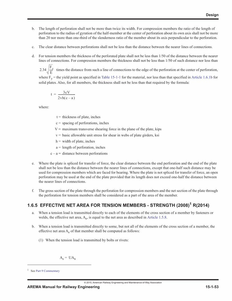
Design
© 2015, American Railway Engineering and Maintenance-of-Way Association
AREMA Manual for Railway Engineering 15-1-53
1
3
4
b. The length of perforation shall not be more than twice its width. For compression members the ratio of the length of perforation to the radius of gyration of the half-member at the center of perforation about its own axis shall not be more than 20 nor more than one-third of the slenderness ratio of the member about its axis perpendicular to the perforation.
c. The clear distance between perforations shall not be less than the distance between the nearer lines of connections.
d. For tension members the thickness of the perforated plate shall not be less than 1/50 of the distance between the nearer lines of connections. For compression members the thickness shall not be less than 1/50 of such distance nor less than
times the distance from such a line of connections to the edge of the perforation at the center of perforation,
where Fy = the yield point as specified in Table 15-1-1 for the material, nor less than that specified in Article 1.6.1b for solid plates. Also, for all members, the thickness shall not be less than that required by the formula:
where:
e. Where the plate is spliced for transfer of force, the clear distance between the end perforation and the end of the plate shall not be less than the distance between the nearer lines of connections, except that one-half such distance may be used for compression members which are faced for bearing. Where the plate is not spliced for transfer of force, an open perforation may be used at the end of the plate provided that its length does not exceed one-half the distance between the nearer lines of connections.
f. The gross section of the plate through the perforation for compression members and the net section of the plate through the perforation for tension members shall be considered as a part of the area of the member.
1.6.5 EFFECTIVE NET AREA FOR TENSION MEMBERS - STRENGTH (2008)1 R(2014)a. When a tension load is transmitted directly to each of the elements of the cross section of a member by fasteners or
welds, the effective net area, Ae, is equal to the net area as described in Article 1.5.8.
b. When a tension load is transmitted directly to some, but not all of the elements of the cross section of a member, the effective net area Ae of that member shall be computed as follows:
(1) When the tension load is transmitted by bolts or rivets:
t = thickness of plate, inchesc = spacing of perforations, inches
V = maximum transverse shearing force in the plane of the plate, kipsv = basic allowable unit stress for shear in webs of plate girders, ksih = width of plate, inchesa = length of perforation, inches
c – a = distance between perforations
1 See Part 9 Commentary
Ae = UAn
2.34FyE-----
t 3cV2vh c a–---------------------------=
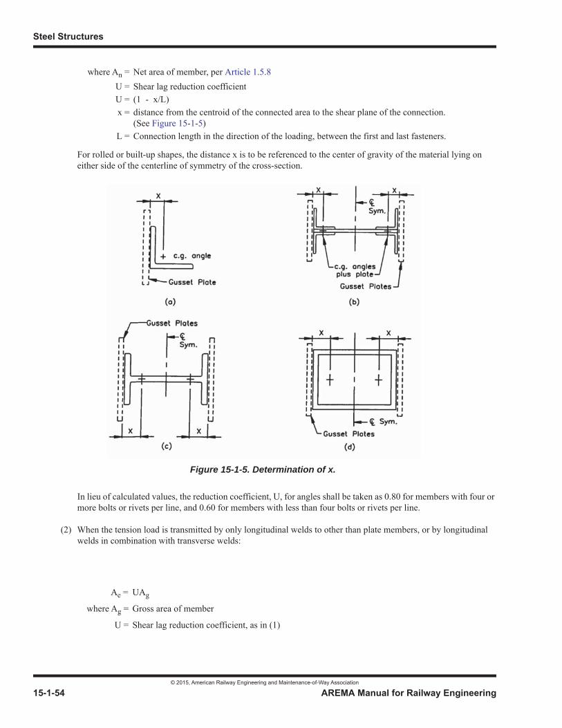
Steel Structures
© 2015, American Railway Engineering and Maintenance-of-Way Association
15-1-54 AREMA Manual for Railway Engineering
For rolled or built-up shapes, the distance x is to be referenced to the center of gravity of the material lying on either side of the centerline of symmetry of the cross-section.
In lieu of calculated values, the reduction coefficient, U, for angles shall be taken as 0.80 for members with four or more bolts or rivets per line, and 0.60 for members with less than four bolts or rivets per line.
(2) When the tension load is transmitted by only longitudinal welds to other than plate members, or by longitudinal welds in combination with transverse welds:
where An = Net area of member, per Article 1.5.8U = Shear lag reduction coefficientU = (1 - x/L)x = distance from the centroid of the connected area to the shear plane of the connection.
(See Figure 15-1-5)L = Connection length in the direction of the loading, between the first and last fasteners.
Ae = UAg
where Ag = Gross area of member
U = Shear lag reduction coefficient, as in (1)
Figure 15-1-5. Determination of x.
Design
© 2015, American Railway Engineering and Maintenance-of-Way Association
AREMA Manual for Railway Engineering 15-1-55
1
3
4
(3) When the tension load is transmitted by only welds transverse to the direction of loading:
(4) When the tension load is transmitted to a plate by longitudinal welds, welds shall be on both edges, for a length not less than the distance between the welds:
For L 2w . . . . . . . . . . . . . . . . . . . . . . U = 1.00
For 2w > L 1.5w . . . . . . .. . . . . . . . .U = 0.87
For 1.5w >L w . . . . . . . . . . . . . . . . .U = 0.75
1.6.6 EFFECTIVE AREA FOR TENSION MEMBERS - FATIGUE (2007)1 R(2014)
a. When a tension load is transmitted directly to all of the elements of the cross section of a member by fasteners or welds, the effective net area, Ae, is equal to the net area, An, as described in Article 1.5.8.
b. When a tension load is transmitted directly to some, but not all, of the elements of the cross section of a member, the effective net area, Ae, of that member shall be taken as the sum of the net areas of the component parts directly loaded.
c. When a tension load is transmitted directly to some, but not all, of the elements of the cross section of a member, the effective gross area of that member shall be taken as the sum of the gross areas of the component parts directly loaded.
SECTION 1.7 MEMBERS STRESSED PRIMARILY IN BENDING
1.7.1 PROPORTIONING GIRDERS AND BEAMS (2004)2 R(2014)
a. Plate girders, I-beams, and other members subject to bending that produces tension on one face, shall be proportioned by the moment of inertia method. The neutral axis shall be considered as the center of gravity of the gross section. The tensile stress shall be computed from the moment of inertia of the entire net section and the compressive stress from moment of inertia of the entire gross section.
b. Where the compression flange is not fully supported laterally, the flexural member shall be proportioned so that the ratio of the distance between points of lateral supports and the radius of gyration of the compression flange, including that portion of the web area on the compression side of the axis of bending about an axis in the plane of the web, shall not exceed:
Ae = Area of directly connected elements
Ae = UA
where A= area of plateL= length of weldw= distance between welds
1 See Part 9 Commentary2 See Part 9 Commentary
Steel Structures
© 2015, American Railway Engineering and Maintenance-of-Way Association
15-1-56 AREMA Manual for Railway Engineering
where:
1.7.2 FLANGE SECTIONS (1994)1 R(2014)
1.7.2.1 Riveted or Bolted Construction
a. Flanges of plate girders should be made without side plates.
b. Where flanges of plate girders are subjected to transverse local bending from bridge ties, the minimum angle thickness shall be 5/8 inch where cover plates are used and 3/4 inch where cover plates are not used.
c. Where cover plates are used, at least one plate of each flange shall extend the full length of the girder or beam. Any cover plate which is not full length shall extend beyond the theoretical end far enough to develop the capacity of the plate, or shall extend to a section where the stress in the remainder of the girder or beam flange is equal to the allowable fatigue stress, whichever extension is greater. The term “theoretical end of cover plate” refers to the section where the stress in the flange without the cover plate equals the allowable stress, exclusive of fatigue considerations.
1.7.2.2 Welded Construction
a. Flanges of welded plate girders shall be made using only one plate in each flange, i.e. without cover plates. Side plates shall not be used in welded construction. The thickness and width of the flange plate may be varied by butt welding parts of different thickness or width with transitions conforming to the requirements of Article 1.10.1.
b. Not more than one cover plate may be used on each flange of a rolled beam. Such cover plates shall be full length and of uniform thickness and width, and shall be connected to the flange of the rolled beam with continuous fillet welds of sufficient strength to transmit the horizontal shear into the cover plate. The thickness of a cover plate shall not be greater than 1.5 times the thickness of the flange to which it is attached.
1.7.3 THICKNESS OF WEB PLATES (2004)2 R(2014)
a. The thickness of the webs of plate girders without longitudinal stiffeners shall not be less than:
of the clear distance between the flanges, except that if the extreme fiber stress in the compression flange is less than the allowable, the above calculated thickness may be divided by the factor:
Fy = the yield point, psi, as specified in Table 15-1-1 for the material.
1 See Part 9 Commentary2 See Part 9 Commentary
5.55 EFy-----
0.18FyE-----
Pc
f-----

Design
© 2015, American Railway Engineering and Maintenance-of-Way Association
AREMA Manual for Railway Engineering 15-1-57
1
3
4
where:
b. The thickness of the webs of plate girders with longitudinal stiffeners, proportioned in accordance with Article 1.7.8,shall not be less than 1/2 that determined in paragraph a.
c. The thickness of the webs of plate girders with or without longitudinal stiffeners shall not be less than 1/6 the thickness of the flange.
1.7.4 FLANGE-TO-WEB CONNECTION OF PLATE GIRDERS (2009)1 R(2014)
a. The flanges of plate girders shall be sufficiently connected to the web to transmit to the flange the horizontal shear force at any point together with the force from any load that is applied directly on the flange. Where the ties bear directly on the flange, one wheel load, including 80% impact, shall be assumed to be distributed over 3 feet. On ballasted deck girders, the wheel load, including 80% impact, shall be assumed to be distributed over 5 feet.
b. Flange to web joints of welded plate girders:
(1) Flange to web joints on welded plate girders shall be identical welds for both compression and tension flanges.
(2) Deck plate girders and stringers. For open and non-composite, non-ballasted decks, the flange-to-web joints shall be made using continuous, complete joint penetration (CJP) or if directed by the engineer, partial joint penetration (PJP) groove welds or fillet welds. If PJP groove welds or fillet welds are used, the root opening and/or fillet weld reinforcement shall be proportioned such that the fatigue strength of the joint is controlled by weld toe cracking and not throat cracking as calculated using the provisions of Section 5.4 in Table 15-1-9.
For ballasted, welded steel plate or composite concrete decks, the flange to web joint may be continuous, CJP groove welds, PJP groove welds or fillet welds.
(3) Through plate girders. The flange-to-web joints may be continuous, CJP, PJP, or fillet welded connections.
1.7.5 FLANGE SPLICES (2014)
a. Flange members that are field spliced, or that are shop spliced by riveting and/or bolting, shall be covered by extra material not less in section than the member spliced. There shall be enough fasteners on each side of the splice to transmit to the splice material the force in the part cut. Flange angles shall be spliced with angles. No two elements in the same flange shall be spliced at the same cross section.
b. In shop welded construction, flange members may be shop spliced by riveting or bolting as in paragraph a or by welding as in paragraphs c and d.
c. Welded shop splices shall be made with complete joint penetration groove welds. Article 3.3.1d provides additional information on weld placement.
d. Welded shop splices of rolled beams shall be made with complete joint penetration groove welds at the same cross section. Filling of cope holes is not permitted. Article 3.3.1e provides additional information on weld placement.
Pc = allowable stress in the compression flange, psi, as determined by the applicable formula of Article 1.4.1.
f = the calculated extreme fiber stress in the compression flange, psi.Fy = yield point as specified in Table 15-1-1 for the material
1 See Part 9 Commentary
Steel Structures
© 2015, American Railway Engineering and Maintenance-of-Way Association
15-1-58 AREMA Manual for Railway Engineering
1.7.6 WEB SPLICES (1994) R(2014)
a. Splices in the webs of plate girders or rolled beams shall be designed to meet both of the following conditions:
(1) Full shear strength of the web, gross section.
(2) The combination of the full moment strength of the web, net section, with the maximum shear force that can occur at the section where the splice is located.
b. Shop or field web splices in riveted or bolted construction and field web splices in welded construction shall be made using splice plates on each side of the web, of the strength required by paragraph a. The net moment of inertia of these web splice plates shall not be less than that of the web.
c. Shop web splices in welded construction may be made as indicated in paragraph b, or may be welded. Welded shop splices shall be made with full penetration groove welds, and the entire cross section shall be welded.
1.7.7 STIFFENERS AT POINTS OF BEARING (2012) R(2014)
a. Stiffeners shall be placed in pairs at end bearings of plate girders and beams, and at points of bearing of concentrated loads. They shall extend as nearly as practicable to the edges of the flange to give effective distribution and shall be connected to the web by enough rivets, bolts or welds, to transmit the load. They shall be cut at upper and lower ends to clear the fillet or weld connecting flange plate to web, as applicable. Angle stiffeners shall not be crimped.
b. The outstanding portion of a bearing stiffener shall meet the width-thickness ratio requirements for outstanding elements in compression.
c. Bearing stiffeners shall be designed as columns, assuming the column section to comprise the pair of stiffeners and a centrally located strip of the web whose width is equal to 25 times its thickness at interior stiffeners or a width equal to 12 times its thickness when the stiffeners are located at the end of the web. The effective length shall be taken as three-quarters of the length of the stiffeners in computing the ratio l/r.
d. Bearing stiffeners shall also be designed for bearing, without considering any part of the web. Only that part of the outstanding leg of an angle stiffener or that part outside the corner clip of a plate stiffener, which is in contact with the flange angle or flange plate, shall be considered effective in bearing. Where bearing stiffeners are welded to the flange in compliance with Part 3, Fabrication, Article 3.1.10a, an area equal to the length of the full penetration groove weld multiplied by the stiffener thickness shall be considered effective in bearing.
1.7.8 WEB PLATE STIFFENERS (INTERMEDIATE TRANSVERSE AND LONGITUDINAL) (2012)1 R(2014)
a. Where the depth of the web between the flanges or side plates of a riveted, bolted or welded plate girder exceeds times its thickness, it shall be transversely stiffened by pairs (except as noted in paragraph c) of angles
riveted or bolted, or of plates welded, to the web. The actual clear distance, da, between intermediate transverse stiffeners shall not exceed 96 inches, nor the clear distance between flanges or side plates, nor d. The maximum clear distance, d, inches, between intermediate transverse stiffeners to preclude web shear buckling is given by the formula:
1 See Part 9 Commentary
2.12 E Fy
d 1.95t ES---=
Design
© 2015, American Railway Engineering and Maintenance-of-Way Association
AREMA Manual for Railway Engineering 15-1-59
1
3
4
where:
The moment of inertia of the intermediate transverse stiffeners shall not be less than:
taken about the centerline of the web plate in the case of stiffeners furnished in pairs (on each side of web plate) and taken about the face of the web plate in contact with the stiffener in the case of single stiffeners.
where:
b. For intermediate transverse stiffeners, the width of the outstanding leg of each angle, or the width of the welded stiffener plate, shall not be more than 16 times its thickness nor less than 2 inches plus 1/30 of the depth of the girder.
c. Intermediate transverse stiffeners used on one side of the web plate only (single stiffeners), shall be connected to the outstanding portion of the compression flange.
d. All intermediate stiffeners on the track side of through plate girders shall be fastened to the compression flange in order to minimize out-of-plane deformations in the web caused by rotations of the ends of the floorbeam.
e. Intermediate stiffeners on through plate girders located within a distance equal to the depth of the girder from the bearing shall be fastened to the tension flange.
f. Where the depth of the web between the flanges or side plates of a riveted, bolted, or welded plate girder exceeds times its thickness (where f = the calculated compressive bending stress in the flange, psi), it shall be
stiffened by intermediate transverse stiffeners in accordance with paragraphs a, b, and c; and by a longitudinal stiffener. Longitudinal stiffeners are usually placed on one side of the web plate with the transverse stiffeners on the other side. Where longitudinal stiffeners and intermediate transverse stiffeners are on the same side and intersect, the longitudinal stiffener should be continuous and the intermediate transverse stiffener should be discontinuous. The stress in the stiffener (from participation in the girder stress) shall not be greater than the basic allowable bending stress for the material used in the stiffener. See Article 9.1.10.2 for further guidance on detailing intersecting stiffeners.
g. The centerline of a plate longitudinal stiffener or the gage line of an angle longitudinal stiffener shall be D/5 from the inner surface or leg of the compression flange component.
h. The longitudinal stiffener shall be proportioned so that:
t = thickness of web, inchesS = calculated shear stress in the gross section of the web at the point under consideration, psi
Fy = minimum yield point, psi, as specified in Table 15-1-1 for the web material
da = actual stiffener spacing
I = moment of inertia, inches 4
D = depth of web between flanges or side plates, inches
I 2.5da= t 3 D2
d2------ 0.7– where 1 < D/d < 5
4.18 E f
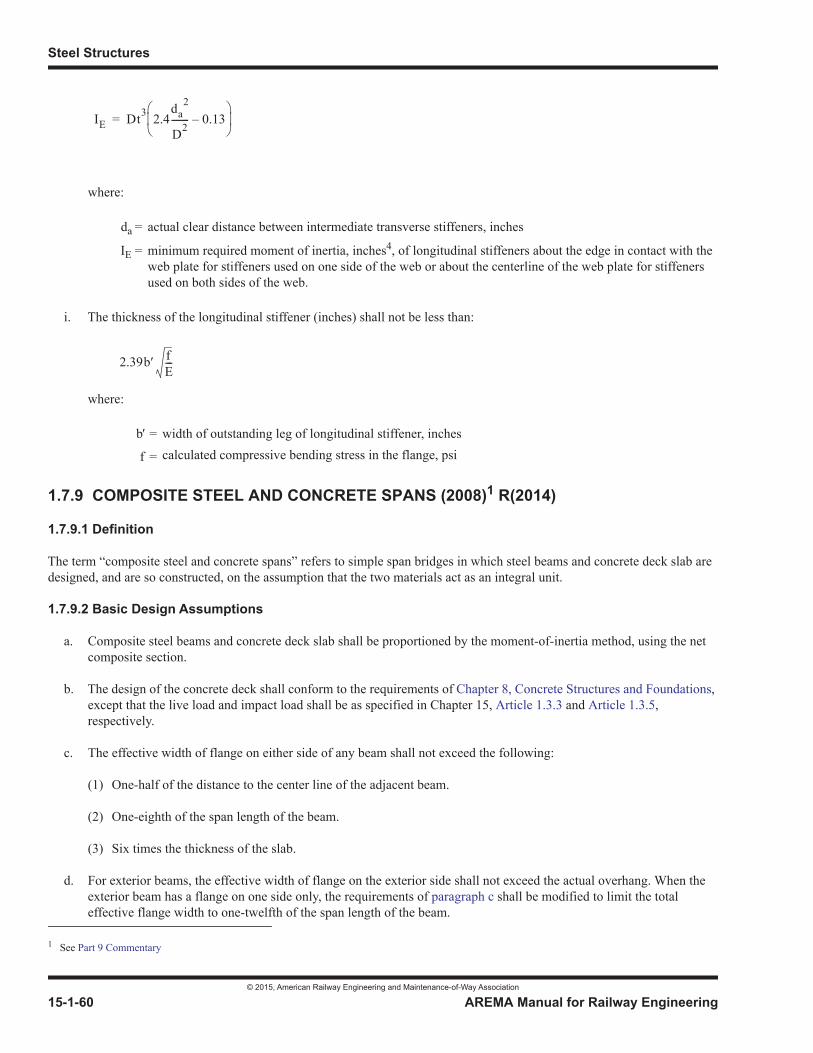
Steel Structures
© 2015, American Railway Engineering and Maintenance-of-Way Association
15-1-60 AREMA Manual for Railway Engineering
where:
i. The thickness of the longitudinal stiffener (inches) shall not be less than:
where:
1.7.9 COMPOSITE STEEL AND CONCRETE SPANS (2008)1 R(2014)
1.7.9.1 Definition
The term “composite steel and concrete spans” refers to simple span bridges in which steel beams and concrete deck slab are designed, and are so constructed, on the assumption that the two materials act as an integral unit.
1.7.9.2 Basic Design Assumptions
a. Composite steel beams and concrete deck slab shall be proportioned by the moment-of-inertia method, using the net composite section.
b. The design of the concrete deck shall conform to the requirements of Chapter 8, Concrete Structures and Foundations,except that the live load and impact load shall be as specified in Chapter 15, Article 1.3.3 and Article 1.3.5,respectively.
c. The effective width of flange on either side of any beam shall not exceed the following:
(1) One-half of the distance to the center line of the adjacent beam.
(2) One-eighth of the span length of the beam.
(3) Six times the thickness of the slab.
d. For exterior beams, the effective width of flange on the exterior side shall not exceed the actual overhang. When the exterior beam has a flange on one side only, the requirements of paragraph c shall be modified to limit the total effective flange width to one-twelfth of the span length of the beam.
da = actual clear distance between intermediate transverse stiffeners, inches
IE = minimum required moment of inertia, inches4, of longitudinal stiffeners about the edge in contact with the web plate for stiffeners used on one side of the web or about the centerline of the web plate for stiffeners used on both sides of the web.
b = width of outstanding leg of longitudinal stiffener, inches
f = calculated compressive bending stress in the flange, psi
1 See Part 9 Commentary
IE Dt3 2.4da
2
D2-------- 0.13–=
2.39b fE---
Design
© 2015, American Railway Engineering and Maintenance-of-Way Association
AREMA Manual for Railway Engineering 15-1-61
1
3
4
e. Composite construction shall not be used for isolated beams.
f. The value of n, the ratio of the modulus of elasticity of steel to the modulus of elasticity of concrete of various design strengths, shall be as given in Chapter 8, Concrete Structures and Foundations.
g. Composite sections should be proportioned so that the neutral axis lies below the top surface of the steel beam. Where concrete is on the tension side of the neutral axis, it shall not be considered in computing moments of inertia or resisting moments.
h. Where no temporary intermediate supports are provided for the beams during casting and curing of the concrete slab, then the steel and concrete dead loads shall be considered as acting on the steel beams alone, and all subsequent loads as acting on the composite section. Where the beams are provided with effective temporary intermediate supports which are kept in place until the concrete has attained 75% of its required 28-day strength, then the concrete dead load and all subsequent loads shall be assumed as acting on the composite section.
i. The effect of creep shall be considered in the design of composite beams which have the dead loads acting on the composite section. Stresses and horizontal shear produced by such dead loads shall be taken as the greater of those computed for the value of n or for 3 times that value.
j. Horizontal shear at the point under consideration between steel beam and concrete slab shall be computed by both the following formulas:
where:
k. The vertical shear shall be considered to be resisted entirely by the web of the steel beam.
1.7.9.3 Shear Transfer Devices
a. Resistance to horizontal shear at the junction of the slab and beam shall be provided by studs or channels welded to the beam flange.
b. The spacing of the shear transfer devices shall be the smaller of the two values determined by dividing the resistance value of the individual device, as specified in Article 1.7.9.3.1, by the value of Sr or Sm as defined in Article 1.7.9.2j.The maximum spacing shall be 2 feet.
Sr = the range of horizontal shear, lb per linear inches
Sm = the maximum horizontal shear, lb per linear inches
Vr = the range of vertical shear due to live load and impact load. At any section, the range of shear shall be taken as the difference in the minimum and maximum shear envelopes, lb
Vm = the maximum vertical shear due to live load and impact load combined with any portion of dead load superimposed on the composite span after the concrete slab is cured, including its weight if temporary intermediate supports during casting and curing are provided, lb
Q = the static moment of the transformed compressive concrete area about the neutral axis of the composite section, inch3
I = the moment of inertia of the composite section. If the dead load shear is included in Sm, the horizontal shear resulting therefrom shall be computed separately as specified in paragraph i and added to the horizontal shear from the other loads, inch4
SrVrQ
I---------- and Sm
VmQ
I------------==
Steel Structures
© 2015, American Railway Engineering and Maintenance-of-Way Association
15-1-62 AREMA Manual for Railway Engineering
c. The shear connectors shall be so spaced that the concrete can be thoroughly compacted and in direct contact with all surfaces of the shear connectors.
d. The clear depth of concrete cover over the top of the shear connectors shall be not less than 2 inches Shear connectors shall penetrate at least 2 inches above the bottom of the slab.
e. The clear distance between the edge of the beam flange and the edge of the shear connector shall be not less than 1 inch for channels and 1-1/2 inches for studs.
f. When stud shear connectors are used, a maximum variation of 1 inch from the location shown on the plans shall be accepted provided that this does not reduce the center to center distance to the nearest stud to less than 2-1/2 inches, or the edge distance required in paragraph e.
1.7.9.3.1 Design Force for Shear Connectors
a. The allowable horizontal design force range per shear connector for fatigue (Sr) when channels are used shall be 2,400(w) lb and 2,100(w) lb for 2,000,000 cycles and over 2,000,000 cycles respectively. The maximum allowable horizontal design force per shear connector (Sm) when channels are used shall be taken as 3,600(w) lb. In the equations for horizontal design force, w is the length of the channel in inches measured in a transverse direction to the flange of the beam.
b. The allowable horizontal design force range per shear connector for fatigue (Sr) when studs are used shall be 10,000(As) lb and 7,000(As) lb for 2,000,000 cycles and over 2,000,000 cycles respectively. The maximum allowable horizontal design force per shear connector (Sm) when studs are used shall be taken as 20,000(As) lb. In the equations for horizontal design force, As is the nominal cross sectional area of the stud, inch2.
c. Where either stud or channel shear connectors are used, fatigue due to primary bending stress range must be checked on the base metal of the member to which the shear connectors are attached as per Table 15-1-9 for longitudinally loaded fillet welded attachments.
1.7.9.3.2 Channels as Shear Transfer Devices
When channels are used as shear transfer devices they shall be from the American Standard series and of ASTM A36 steel. They shall be placed transverse to the beam and with one channel flange welded all around to the flange of the beam with at least 3/16 inch fillet welds.
1.7.9.3.3 Studs as Shear Transfer Devices
a. Where welded studs are used as shear transfer devices they shall be headed, and shall be 3/4 inch or 7/8 inch nominal diameter, and their overall length after welding shall be at least 4 times their diameter.
b. Studs shall conform to the requirements of ASTM A108, grades 1010 through 1020, either semi- or fully-killed.
c. Tensile properties as determined by tests of bar stock after drawing or of finished studs shall conform to the following requirements:
Tensile properties shall be determined in accordance with the applicable sections of ASTM A370. Where fracture occurs outside of the middle half of the gage length, the test shall be repeated.
Tensile strength (min) . . . . . . . . . . . . 60,000 psiElongation (min) . . . . . . . . . . . . . . . . 20% in 2 inchesReduction of area (min) . . . . . . . . . . 50%
Design
© 2015, American Railway Engineering and Maintenance-of-Way Association
AREMA Manual for Railway Engineering 15-1-63
1
3
4
d. Finished studs shall be of uniform quality and condition, free from laps, fins, seams, cracks, twists, bends or other injurious defects. Finish shall be as produced by cold drawing, cold rolling or machining. However, cracks or bursts in the heads of shear connectors do not adversely affect the structural strength or other functional requirements of shear studs, and are not to be considered cause for rejection of the stud, except that where they are deeper than one-half the distance from the periphery of the head to the shank, they may be cause for rejection. Cracks or bursts, as here used, apply to an abrupt interruption of the periphery of the head of the stud by radial separation of the metal.
e. The Contractor shall, upon request by the Engineer, furnish the stud manufacturer’s certification that the studs that are delivered are in accordance with the applicable requirements of this article. Certified copies of the stud manufacturer’s test reports of the last completed set of in-plant quality control mechanical tests of the diameters of studs to be provided, made not more than six months prior to the delivery of the studs, shall be furnished to the Engineer on request.
f. The Engineer may select, at the Contractor’s expense, studs of each type and size used, as necessary for checking the requirements of this article. The cost of these check tests shall be at the Company’s expense.
g. Stud shear connectors shall be of a design suitable for end welding, and shall be end welded to the steel beams with automatically timed stud welding equipment. The equipment and procedure followed in making the welds shall be as recommended by the manufacturer of the type of stud used. The flux and the ceramic arc shield utilized in this procedure shall be furnished by the manufacturer, and shall be compatible with the equipment and procedure used.
h. Before installation, the Contractor shall submit to the Engineer for approval information on the studs to be furnished as follows:
(1) The name of the manufacturer.
(2) A detailed description of the stud and arc shield.
(3) A certification from the manufacturer that the stud weld base is qualified as specified in paragraph g. Qualification test data shall be retained in the files of the manufacturer.
i. The first two stud shear connectors welded on each member, after being allowed to cool, shall be bent 45 degrees by striking the stud with a hammer. If failure occurs in the weld zone of either stud, the procedure shall be corrected and two more studs shall be welded to the member and tested. Two consecutive studs shall be satisfactorily welded and tested before any more production studs are welded to the member. The foregoing testing shall be performed after any change in the welding procedure. If failure occurs in the stud shank, an investigation shall be made to ascertain and correct the cause before further welds are made. Studs tested that show no sign of failure shall be left in the bent position.
j. Where the automatically made weld joining the stud to the beam is not a full 360 degrees, the stud shall be removed and replaced, or, at the option of the Contractor, the weld may be repaired by adding a 3/16 inch fillet weld in place of the lack of weld, using the shielded metal- arc process with low-hydrogen welding electrodes.
k. Before welding a new stud where a defective one has been removed, the area shall be ground smooth and flush, or in the case of a pullout of metal, the pocket shall be filled with weld metal using the shielded metal-arc process with low-hydrogen welding electrodes and then ground flush.
l. In addition to the inspection requirements of paragraph i, the Inspector shall visually inspect all studs after all studs have been welded to a beam, and shall give each stud a light blow with a hammer. Any stud which does not have a complete weld, any stud which does not emit a ringing sound when given the light blow with the hammer, any stud which has been repaired by welding or any stud which has less than normal reduction in height due to welding, shall be struck with a hammer and bent 15 degrees from the correct axis of installation, and, in the case of a defective or repaired weld, the stud shall be bent 15 degrees in the direction that will place the defective portion of the weld in the
Steel Structures
© 2015, American Railway Engineering and Maintenance-of-Way Association
15-1-64 AREMA Manual for Railway Engineering
greatest tension. Studs that crack either in the weld or in the shank shall be replaced. Studs tested that show no sign of failure shall be left in the bent position.
m. If during the progress of the work, inspection and testing indicate that the shear connectors are not satisfactory, the Contractor will be required at his expense to make such changes in welding procedure, welding equipment and type of shear connector as necessary to secure satisfactory results.
1.7.9.4 Deflection
Composite spans shall be designed so that the deflection, computed using the composite section, for the live load plus impact load condition does not exceed 1/640 of the span length center to center of bearings.
1.7.9.5 Camber
Beams in composite construction shall be cambered when the dead load deflection exceeds 1 inch. Dead load deflection in composite construction, where the beams are provided with falsework or other effective intermediate supports during casting and curing of the concrete slab, shall be computed using the composite section, but including the effect of creep as specified inArticle 1.7.9.2i. If such supports are not provided, the dead load deflection shall be computed using the steel beams alone.
1.7.10 RIGID FRAME STRUCTURES (2008)1 R(2014)
1.7.10.1 Definition
The term “rigid frame” is used to denote a load-carrying frame in which the horizontal member is structurally integral with theupright supports; either or both may vary in section.
1.7.10.2 Basic Design Assumptions
a. Moments, shears and reactions shall be determined by recognized methods of analysis based on gross moments of inertia and gross areas of members. If the structure has a box type cross section, with perforated cover plates, the effective area of the cover plates, as defined in Article 1.2.5, shall be used in calculating deformations caused by axial stress.
b. Hinged bearings for the upright supports are preferred. Where hinged bearings are not practicable, or where details may render them inoperative, the analysis of the rigid frames shall be made assuming (1) fixed bases, (2) hinged bases, and the design shall be based on the larger stress so determined.
c. Loads and forces shall include those specified in Article 1.3.1a, except that the longitudinal forces as specified in Article 1.3.12 shall be applied at the mid height of the horizontal member of the frame. In addition to the loads and forces specified in Article 1.3.1a, rigid frame structures shall be proportioned for the most unfavorable combinations of those loads and forces with loads and forces resulting from the following:
(1) Earth pressure, which shall be assumed to act on both ends, on one end only, or be omitted, whichever requires the largest section. Where granular back fill is used behind the cut off walls, only active pressure at both ends shall be included. Earth pressure shall be determined in accordance with the recommendations given in Chapter 8, Concrete Structures and Foundations.
(2) Temperature change, which shall be based on a range of from plus 40 degrees F to minus 60 degrees F from the temperature expected at time of closure. Closure must be effected when the actual temperature is within 10 degrees F of the assumed figure; where this is not possible, the adequacy of the structure must be investigated for the actual temperature, and reinforcement added if necessary.
1 References, Vol. 44, 1943, pp. 413, 670, 685; Vol. 60, 1959, pp. 506, 1098; Vol. 63, 1962, pp. 386, 699; Vol. 70, 1969, p 241.
Design
© 2015, American Railway Engineering and Maintenance-of-Way Association
AREMA Manual for Railway Engineering 15-1-65
1
3
4
(3) Rib-shortening and elastic yielding of the supports, which must be investigated and their effect included, if larger sections would be required thereby.
1.7.10.3 Foundations
a. Footings shall be founded on rock, on substantially unyielding material, or on piles driven to an unyielding stratum. If the footings are founded on piles, there shall be a sufficient number of battered piles to provide the necessary resistance to the horizontal thrust.
b. Where conditions make it impracticable to provide resistance to the horizontal thrust by means of direct bearing or by battered piles, steel tie rods may be used. Such tie rods shall be encased in concrete with a minimum cover on all sides of 6 inches.
1.7.10.4 Spacing
In addition to the requirements of Article 1.2.4, the distance between frames shall be great enough to facilitate the attachment of bracing between them, and for painting.
1.7.10.5 Deflection
The structure shall be so proportioned and designed that the computed total elastic deflection at the mid span of the horizontalmember for live load plus impact load shall not exceed 1/640 of the distance center to center of the upright supports.
1.7.10.6 Camber
Rigid frame structures in which the distance center to center of upright supports is 60 feet or less need not be cambered. Rigidframe structures in which that length exceeds 60 feet shall have camber equal to the deflection produced by the dead load plus a load of 3,000 lb per foot of track.
1.7.10.7 Impact Load
In computing impact load in accordance with Article 1.3.5, L shall be considered as the length, in feet, center to center of the upright supports for longitudinal rigid frames, and, for transverse rigid frames, L shall be considered as the length in feet of the longer adjacent supported longitudinal beam or girder.
1.7.10.8 Stresses
The stresses resulting from earth pressure, temperature change, rib shortening and elastic yielding of supports shall be combined with the stresses resulting from the loadings of Article 1.3.14.3a, and the member shall be proportioned for the stresses specified in Article 1.3.14.3a. The provisions of Article 1.3.14.3b for combinations including stresses resulting from other lateral loads and/or longitudinal load shall apply.
1.7.10.9 Bracing
a. Bracing for rigid frames shall conform to the requirements of Section 1.11, Bracing, with the modifications of this section. There shall be continuous bracing in the planes of the compression flanges of both horizontal and vertical members. If the top flanges are rigidly connected to a steel deck plate, or laterally restrained by a cast-in-place reinforced concrete deck, only such top lateral bracing as is required for erection purposes need be provided.
b. There shall be cross frames or diaphragms between the main members of the rigid frames so placed as to act with the horizontal bracing to provide lateral support for the compression flange.
Steel Structures
© 2015, American Railway Engineering and Maintenance-of-Way Association
15-1-66 AREMA Manual for Railway Engineering
1.7.10.10 Stiffeners at Points of Bearing
a. Where the bottom flange of the horizontal member in a rigid frame extends across the upright members and bears thereon, there shall be bearing stiffeners directly above the flanges of the upright members, milled to fit tight against the bottom flange of the horizontal member and designed to transmit the stress in the flanges of the vertical members to the web of the horizontal member.
b. Where the inner flanges of the upright members are made continuous up to the top flange of the horizontal member, the ends of the bottom flange of the horizontal member shall be milled to bear against the inner flanges of the upright members. There shall be bearing stiffeners on the webs of the vertical members opposite the milled ends of the bottom flange of the horizontal member, designed to transmit the force from that flange to the webs of the vertical members.
c. Where rounded corners at the junction of horizontal and vertical members are used, they shall be proportioned by recognized methods of analysis and adequately stiffened.
1.7.10.11 Splices
Splices in any component of the rigid frame structure shall be designed to develop the full strength of that component.
SECTION 1.8 FLOOR MEMBERS AND FLOORBEAM HANGERS
1.8.1 END FLOORBEAMS (1993) R(2014)
Spans with floor systems shall have end floorbeams unless otherwise specified. Except where other means are provided, end floorbeams shall be proportioned for lifting the span without exceeding the basic allowable stresses by more than 50%.
1.8.2 FLOORBEAMS AND FLOORBEAM HANGERS (1993) R(2014)
a. Floorbeams should be perpendicular to the center line of the track.
b. The main material of floorbeam hangers shall not be coped or notched. Built-up hangers shall have solid or perforated web plates, or lacing. The minimum thickness of main material of floorbeam hangers shall be 1/2 inch.
1.8.3 END CONNECTIONS OF FLOOR MEMBERS (1993)1 R(2014)
a. Beams in solid floor construction, stringers and floorbeams shall have end connection angles to ensure the necessary flexibility in the connection. Welding shall not be used to connect the flexing leg.
b. The flexing legs of the connection angles shall not be less than 4 inches width and 1/2 inch finished thickness.
c. For stringers, the gage from back of angle to first line of fasteners in the flexing legs of the connection angles over the top one-third of the stringer depth shall not be less than the quantity:
1 See Part 9 Commentary
lt8----
Design
© 2015, American Railway Engineering and Maintenance-of-Way Association
AREMA Manual for Railway Engineering 15-1-67
1
3
4
where:
SECTION 1.9 RIVETED AND BOLTED CONSTRUCTION
1.9.1 PITCH AND GAGE OF FASTENERS (1993) R(2014)
The pitch of fasteners is the distance between centers of adjacent fasteners, measured along one or more lines of fasteners. Thegage of fasteners is the distance between adjacent lines of fasteners, or the distance from the back of angle or other shape to the first line of fasteners.
1.9.2 GRIP OF RIVETS (1993) R(2014)
Where the grip of rivets carrying calculated stress exceeds 4.5 times the diameter, the number of rivets shall be increased at least 1% for each additional 1/16 inch of grip. Where the grip equals or exceeds 6 times the nominal diameter, the body shall be tapered from the head for a distance not less than 3.42 times the nominal diameter, but not more than 4-3/4 inches. The body diameter at the head shall be 1/32 inch greater and where not tapered, 1/64 inch less than the nominal diameter.
1.9.3 MINIMUM SPACING OF FASTENERS (1993) R(2014)
a. The distance between centers of fasteners shall not be less than 3 times the diameter of the fasteners.
b. The distance between high-strength bolts measured in the line of force from the center line of a bolt to the center line of an adjacent bolt shall not be less than:
where:
1.9.4 EDGE DISTANCE OF FASTENERS (2005)1 R(2014)
a. The distance from the center of a fastener to a sheared edge shall not be less than 1.75 times the diameter of the fastener. The distance from the center of a fastener to a rolled, planed, or thermally-cut edge shall not be less than 1.5 times the diameter of the fastener. The minimum edge distance may be decreased to 1.25 times the diameter of the fastener in flanges of rolled beams and channels if necessary to meet required clearances.
b. The distance from the free edge of an outside plate or shape to the first line of fasteners shall not exceed:
l = length of stringer span, inchest = thickness of angle, inches
d = diameter of bolt, inchesfp = calculated bearing stress due to design load, ksi
Fu = lowest specified minimum tensile strength of the connected part, ksi
1 See Part 9 Commentary
2df p
Fu----------- d
2---+
Steel Structures
© 2015, American Railway Engineering and Maintenance-of-Way Association
15-1-68 AREMA Manual for Railway Engineering
1-1/2 + 4t, nor 6 inches
where:
c. The distance between the center of the nearest bolt and that end of the connected member towards which the pressure of the bolt is directed shall not be less than:
where:
1.9.5 SIZES OF FASTENERS IN ANGLES (1993) R(2014)
In angles, the size of which is determined by calculated stress, the diameter of the fasteners shall not exceed one-quarter of thewidth of the leg in which they occur. In angles, the size of which is not so determined, 1 inch fasteners may be used in 3-1/2 inch legs, 7/8 inch fasteners in 3 inch legs, and 3/4 inch fasteners in 2-1/2 inch legs.
1.9.6 FASTENERS IN INDIRECT SPLICES (2015)1
For riveted construction only, where splice plates are not in direct contact with the parts which they connect, there shall be rivets on each side of the joint in excess of the number required in the case of direct contact, to the extent of two extra lines at each end of each intervening plate. Where high-strength bolts are used, no additional bolts need be added for indirect splices,nor for connections or splices with fillers provided that all surfaces have a slip resistance equal to or greater than the ultimatestrength of the main element to which the load is being transferred, subject to the recommendations of Article 1.5.11a.
SECTION 1.10 WELDED CONSTRUCTION
1.10.1 TRANSITION OF THICKNESS OR WIDTHS IN WELDED BUTT JOINTS (2012)2R(2014)
a. Where butt joints subject to axial or flexural tensile stress, or to flexural compressive stress, are used to join material ofdifferent thicknesses, there shall be a smooth transition between offset surfaces at a slope not greater than 1 in 2.5 with the surface of either part. The transition of thickness may be accomplished by sloping weld faces or by chamfering the thicker part, or by a combination of the two methods. The fatigue stress range for the transitional detail shall be as allowed by Table 15-1-9.
t = thickness, inches, of the plate or shape
d = diameter of bolt, inchesfp = calculated bearing stress due to design load, ksi
Fu = lowest specified minimum tensile strength of the connected part, ksi
1 See Part 9 Commentary2 See Part 9 Commentary
2df p
Fu-----------
Design
© 2015, American Railway Engineering and Maintenance-of-Way Association
AREMA Manual for Railway Engineering 15-1-69
1
3
4
b. Where butt joints subject to axial or flexural tensile stress, or to flexural compressive stress, are used to join material ofdifferent widths, there shall be a common longitudinal axis of symmetry, and there shall be a smooth transition between offset edges at a slope of not greater than 1 in 2.5 with the edge of either part or the offset edges shall be transitioned with a radius of not less than 2 feet with the point of tangency to the narrower width preferably a minimum of 3 inches from the center of the butt joint.
c. Where butt joints subject to axial compressive stress are used to join material of different thickness and the offset between surfaces is equal to or less than the thickness of the thinner plate, the face of the weld shall have a slope of not greater than 1 in 2.5 with the surface of the thinner part. When the offset is greater than the thickness of the thinner plate the transition of thickness shall be as described in paragraph a.
d. Where butt joints subject to axial compressive stress are used to join material of different widths, reduction in width of the wider plate to effect a smooth transition is preferable, but is not mandatory.
1.10.2 PROHIBITED TYPES OF JOINTS AND WELDS (2008)1 R(2014)
a. Those listed as such in AWS D1.5.
b. Plug or slot welds (This does not prohibit the use of fillet welds in holes or slots.)
c. Intermittent welds.
d. Butt joints of plates with transition of both thickness and width, and transmitting other than axial compressive stress.
e. Partial joint penetration groove welds transverse to the direction of stress.
f. Transverse tack welds on tension flanges of flexural members.
g. Highly constrained joints. Welded connections shall be detailed to avoid welds that intersect or overlap. Welded attachments should be detailed so that the welds parallel to the primary stresses are continuous and the transverse welded connection is discontinuous. If unavoidable, welds in low stress range areas that are interrupted by intersecting members shall be detailed to allow a minimum gap of at least one inch between weld toes and weld terminations and shall be properly designed for the applicable fatigue limit state. (See Commentary)
1.10.3 FILLET WELDS (1993) R(2014)
a. Fillet welds which resist a tensile force which is not parallel to the axis of the weld, or which are proportioned to resist repeated stress, shall not terminate at corners of parts or members, but shall be returned continuously, full size, around the corner for a length equal to twice the weld size where such return can be made in the same plane. End returns shall be indicated on design and detail drawings.
b. Fillet welds in holes or slots may be used to transmit shear in lap joints or to prevent buckling or separation of lapped parts. Fillet welds in a hole or slot shall not overlap.
1.10.4 WELDED ATTACHMENTS (2004)2 R(2014)
a. Where stiffeners, brackets, gussets, clips, or other detail material are welded to members or parts subjected to fatigue conditions, the stress range in base material adjacent to the welds shall not exceed that permitted by Article 1.3.13.
1 See Part 9 Commentary2 See Part 9 Commentary
Steel Structures
© 2015, American Railway Engineering and Maintenance-of-Way Association
15-1-70 AREMA Manual for Railway Engineering
b. An intermediate stiffener shall not be welded to the web of girder for a minimum distance of 6 times the thickness of web starting from the toe of the tension flange to web weld.
c. Wrap-around welds should not be used when an intermediate stiffener is fillet welded to a girder web or flange.
1.10.5 FRACTURE CRITICAL MEMBERS (1994) R(2014)
Welding of Fracture Critical Members shall be in accordance with Section 1.14, Fracture Critical Members.
1.10.6 MATERIAL WELDABILITY (2006) R(2014)
a. When a grade of structural steel is to be supplied and the grade meets the chemical and mechanical properties of ASTM A709, the applicable prequalified procedures of AWS D1.5 shall apply.
b. When a steel listed in Table 15-1-1 is to be supplied, other than a steel described in Paragraph a above or in AWS D1.5 Article 1.2.2, weldability and weld procedure qualification shall be established by the contractor in accordance with AWS D1.5 Article 5.4.3. For weldability and weld procedure qualification of ASTM A709, Grade HPS 70W, the latest edition of the AASHTO document “Guide Specification for Highway Bridge Fabrication with HPS 70W (HPS 485W) Steel” shall be used as a supplement to AWS D1.5. The contractor, rather than the company, shall assume additional costs described in AWS D1.5 Article 5.4.3.2.
c. Welding procedures qualified in accordance with AWS D1.5 for materials 4 inches thick also qualify materials permitted in Table 15-1-1 over 4 inches thick.
SECTION 1.11 BRACING
1.11.1 BRACING OF TOP FLANGES OF THROUGH GIRDERS (2000) R(2014)
The top flanges of through plate girders shall be braced at the panel points by brackets with web plates (knee braces). The brackets shall extend to the top flange of the main girder and be as wide as clearance will allow. They shall be attached securely to a stiffener on the girders and to the top flange of the floorbeam. On solid floor bridges the brackets shall not bemore than 12 feet apart. The brackets shall be designed for the bracing force specified in Article 1.3.11.
1.11.2 LATERAL BRACING (2012)1 R(2014)
a. There shall be bottom lateral bracing in all spans greater than 50 feet long, except that such bracing shall not be required for deck spans having four or more beams per track and a depth of beam less than 72 inches in which either adequate shear transfer to a reinforced concrete deck is provided or the concrete is cast in place to engage not less than 1 inch of the beam flange thickness, or steel or other deck systems providing adequate lateral resistance.
b. There shall be top lateral bracing in all deck spans and in through spans that have sufficient clearance.
c. Where the construction of the floor is such as to afford the specified lateral resistance in deck spans or through plate girder spans, the floor shall be taken as the lateral bracing required in its plane. Loads from such floors shall be transferred to the bearings without introducing torsion into the floor system or main members. Concrete decks are not to be used in through spans unless the deck is isolated from the main girders or trusses.
1 See Part 9 Commentary
Design
© 2015, American Railway Engineering and Maintenance-of-Way Association
AREMA Manual for Railway Engineering 15-1-71
1
3
4
d. Where the bracing is a double system and the members meet the requirements for both tension and compression members, both systems may be considered effective simultaneously.
1.11.3 PORTAL AND SWAY BRACING (1994) R(2014)
a. In through truss spans there shall be portal bracing, with knee braces, as deep as the clearance will allow. There shall be sway bracing at the intermediate panel points if the trusses are high enough to allow a depth of 6 feet or more for such bracing. Where there is not sufficient clearance to allow that depth, the top lateral struts shall be of the same depth as the chord, and there shall be knee braces as deep as the clearance will allow.
b. In deck truss spans there shall be sway bracing at the panel points. The top lateral forces shall be carried to the supports by means of a complete system of bracing.
1.11.4 CROSS FRAMES AND DIAPHRAGMS FOR DECK SPANS (1994)1 R(2014)
a. Cross frames and diaphragms, and their connections, shall be adequate to resist forces induced by out of plane bending and the lateral distribution of loads. Connection plates for cross frames and diaphragms between beams or girders shall be adequately fastened to the web and both the top and bottom flanges of the beams or girders. Connection angles for diaphragms between rolled beams in single track spans, without skew and on tangent alignment, need not be fastened to the flanges.
b. Longitudinal girders or beams having depth greater than 3 -6 and spaced more than 4 feet on centers shall be braced with cross frames. The angle of cross frame diagonals with the vertical shall not exceed 60 degrees.
c. Longitudinal girders or beams not requiring cross frames shall be braced with I-shaped diaphragms which are as deep as girders or beams will permit. Connections to the girder or beam webs for such diaphragms shall be designed to carry shear at least equal to one-half of the shear capacity of the diaphragm.
d. Cross frames or diaphragms shall be used at the ends of spans (except where the girders or beams are framed into floorbeams), and shall be proportioned for centrifugal and lateral forces.
e. In open deck construction, cross frames or diaphragms shall be used at intervals not exceeding 18 feet.
f. Where steel plate, timber or precast concrete decking is utilized in ballasted deck construction, cross frames or diaphragms without top lateral bracing shall be used at intervals not exceeding 12 feet; or with top lateral bracing, at intervals not exceeding 18 feet.
g. Where poured-in-place concrete decking is used in ballasted deck construction, cross frames or diaphragms shall be used at intervals not exceeding 24 feet. For girders or beams up to 4 -6 deep, concrete diaphragms with reinforcement extending through the girders or beams may be used instead of steel diaphragms.
h. Where ballast and track are carried on transverse beams without stringers, the beams shall be connected with at least one line of longitudinal diaphragms per track.
1.11.5 BRACING OF VIADUCT TOWERS AND BENTS (1994) R(2014)
a. The bracing of bents and towers shall consist of double systems of diagonals with struts at caps and bases and at intermediate panel points. In towers supporting two or more tracks there shall be horizontal bracing at the top of the tower to transmit horizontal loads.
1 See Part 9 Commentary
Steel Structures
© 2015, American Railway Engineering and Maintenance-of-Way Association
15-1-72 AREMA Manual for Railway Engineering
b. The bottom struts shall be proportioned for either the calculated forces or force in tension or compression equal to one-quarter of the dead load reaction on one pedestal, whichever is greater. The column bearings shall be designed to allow for the expansion and contraction of the tower bracing.
1.11.6 BRACING MEMBERS USED AS TIES OR STRUTS ONLY (1994) R(2014)
Bracing members used only as ties or struts, to reduce the unsupported length of a member to which they connect, need not be designed for more than 2.5% of the force in that member.
SECTION 1.12 PINS AND PIN-CONNECTED MEMBERS
1.12.1 PINS (2014)1
a. Pins more than 7 inches in diameter shall be forged and should be heat treated by normalizing and tempering.
b. In pins more than 9 inches in diameter, there shall be a hole not less than 2 inches in diameter bored longitudinally on the center line.
c. The turned bodies of pins shall be long enough to extend at the ends 1/4 inch beyond the outside faces of the parts connected. The pins shall be secured by recessed pin nuts or by solid nuts and washers. If the pins are bored, through rods with pin cap plates may be used. The screw ends shall be long enough to allow burring the threads.
1.12.2 SECTION AT PIN HOLES (1993) R(2014)
The net section beyond the pin hole, parallel with the axis of the member, shall not be less than the required net section of themember. The net section through the pin hole, transverse to the axis of the member, shall be at least 40% greater than the required net section of the member. The ratio of the transverse net width through the pin hole to the thickness of the segment shall not be more than eight.
1.12.3 REINFORCING PLATES AT PIN HOLES (1993) R(2014)
Where necessary for the required section or bearing area, the section at pin holes shall be increased on each segment by platesso arranged as to reduce the eccentricity of the segment to a minimum. One plate on each side shall be as wide as the outstanding flanges will allow. At least one full width plate on each segment shall extend to the far edge of the stay plate, andthe others not less than 6 inches beyond the near edge. These plates shall be connected adequately to transmit the bearing pressure and so arranged as to distribute it uniformly over the full section.
1.12.4 FORKED ENDS OF COMPRESSION MEMBERS (1993) R(2014)
Forked ends of compression members shall be permitted only where unavoidable. There shall be enough pin plates on forked ends to make the section of each jaw equal to that of the member. The pin plates shall be long enough to develop the pin plate beyond the near edge of the stay plate, but not less than the length required by Article 1.12.3.
1 See Part 9 Commentary

Design
© 2015, American Railway Engineering and Maintenance-of-Way Association
AREMA Manual for Railway Engineering 15-1-73
1
3
4
SECTION 1.13 CONTINUOUS AND CANTILEVER STEEL STRUCTURES1
1.13.1 DEFINITION (2008) R(2014)
a. A continuous steel structure is one in which the principal load-carrying beams, girders, or trusses have moment-carrying capacity without interruption throughout at least two adjacent spans. The calculation of reactions and forces involves the deformations due to stress in the member or members of the structure, and the structure is therefore said to be statically indeterminate.
b. A cantilever steel structure is one in which the principal load-carrying beams, girders or trusses have moment carrying capacity throughout one span without interruption, and project or cantilever over at least one support of that span into the adjacent span or spans, with an interruption in the moment-carrying capacity of the structure where it supports the adjacent span or spans. The calculation of reactions and forces, except in the case where two projections or cantilever arms are joined by a shear connection without a suspended span between them, are independent of the deformations due to stress in the member or members in the structure, and the structure is therefore said to be statically determinate. In the exception stated, the structure is statically indeterminate, as noted for continuous structures in paragraph a.
1.13.2 BASIC DESIGN ASSUMPTIONS (2008) R(2014)
a. Moments, shears and reactions shall be determined by recognized methods of analysis. In the case of the statically indeterminate structures described under Article 1.13.1, the gross moments of inertia for flexural members, and the gross and effective areas, as defined in Article 1.2.5a, for truss members, shall be used in the calculations.
b. Bearing supports should be constructed so that the supports may be considered to be unyielding. When such construction is not practical, provision shall be made in the design to allow for settlement of the supports based on reasonable assumptions as to the magnitude of the settlement.
c. A portion or portions of the live load specified in Article 1.3.3 and positioning on the structure shall be selected so as to produce maximum effects. In case of discontinuous loading not more than two separated loaded lengths shall be used, with one of the lengths subjected to uniform load only, and with the other subjected to the load headed in either direction.
1.13.3 DEFLECTION (2008) R(2014)
a. The deflections of the individual spans of continuous or cantilever structures shall be computed for live load plus impact load, placed so as to produce maximum downward deflection in that span. In this computation, gross moment of inertia shall be used for flexural members, and gross or effective area, as defined in Article 1.2.5a, shall be used for truss members.
b. The structure shall be proportioned and designed so that the computed downward deflection within any span which has moment-carrying capacity throughout its length shall not exceed 1/640 of that span length. In the case of cantilever structures, the computed downward deflection at the end of the cantilever arm shall not exceed 1/250 of the length of that arm and the downward deflection of a suspended simple span shall not exceed 1/640 of the length of that span.
1.13.4 CAMBER (2008) R(2014)
The camber of trusses shall be equal to the deflection produced by dead load plus a continuous uniform load of 3,000 lb per foot of track. The camber of plate girders shall be equal to the deflection produced by the dead load only. Rolled beams shall not be cambered, but shall be fabricated and erected so that any natural camber in the beam is upward.
1 References, Vol. 58, 1957, pp. 694, 1203; Vol. 59, 1958, pp. 705, 1196; Vol. 63, 1962, pp. 386, 699; Vol. 70, 1969, p. 241; Vol. 79, 1978, p. 45; Vol. 97, p. 172.
Steel Structures
© 2015, American Railway Engineering and Maintenance-of-Way Association
15-1-74 AREMA Manual for Railway Engineering
1.13.5 IMPACT LOAD (2008) R(2014)
In computing impact load in accordance with Article 1.3.5, L shall be taken as the length, in feet, of the longest span, center to center of supports within the structure; except that, in the case of simple suspended spans in cantilever structures, the length of that span shall be used as L in computing impact loads in that span.
1.13.6 UPLIFT (2015)1
Span lengths should be selected so that the dead load reaction at any support of the group will be at least 1.5 times the upliftfrom live load and impact load. Where dead load is insufficient, additional anchorage shall be provided in a vertical direction.
1.13.7 BRACING (2008) R(2014)
Bracing for continuous spans shall be as required by Section 1.11, Bracing, and, in addition, top flanges of through plate girder spans in regions of negative moment as well as in regions of positive moment shall be braced as required in Article 1.11.1, and bottom flanges of all beam and girder spans, regardless of length, shall have a continuous lateral bracing system.
1.13.8 LONGITUDINAL STIFFENERS (2010)2
a. Longitudinal stiffeners shall be placed as specified by Article 1.7.8f to provide flexural stiffness to the web plate over supports of continuous or cantilever deep girders, where there is negative moment. Longitudinal stiffeners are usually placed on one side only of the web plate with transverse stiffeners on the other side. Where bearing stiffeners are placed on both sides of the web and the longitudinal stiffeners intersect with bearing stiffeners, the longitudinal stiffener should be discontinuous with the bearing stiffener. The stress in the stiffener (from participation in the girder stress) shall not be greater than the basic allowable bending stress for the material used in the stiffener. Longitudinal stiffeners shall also be used at other locations as specified by Article 1.7.8f. See Article 9.1.10.2 for further guidance on detailing intersecting stiffeners.
b. The center line of a plate longitudinal stiffener or the gage line of an angle longitudinal stiffener shall be D/5 from the inner surface or leg of the compression flange component.
c. The longitudinal stiffener shall be proportioned so that:
where:
d. The thickness of the longitudinal stiffener shall not be less than
1 See Part 9 Commentary2 See Part 9 Commentary
IE = minimum required moment of inertia of longitudinal stiffeners about the edge in contact with the web plate, inch4
D = clear distance between flange, inchest = thickness of the web plate, inchesd = clear distance between the transverse stiffeners, inches
IE D= t3 2.4 d2
D2------ 0.13–
Design
© 2015, American Railway Engineering and Maintenance-of-Way Association
AREMA Manual for Railway Engineering 15-1-75
1
3
4
where:
1.13.9 COVER PLATES (2008) R(2014)
The requirements for cover plates in Article 1.7.2 shall apply except as modified in Article 1.13.9.1 and Article 1.13.9.2wherein the term “theoretical end of cover plate” refers to the section where the stress in the flange without that cover plateequals the allowable stress, exclusive of fatigue considerations.
1.13.9.1 For Riveted or Bolted Construction
Partial length cover plates shall extend beyond the theoretical end far enough to develop the capacity of the plate, or shall extend to a section where the stress in the remainder of the girder flange is equal to the allowable fatigue stress, whichever extension is greater.
1.13.9.2 For Welded Construction
a. Flanges of welded plate girders shall be made using only one plate in each flange (i.e. without cover plates).
b. Partial length cover plates may be used on rolled beam spans under the following conditions:
(1) Partial length cover plates should be limited to one on any flange. The maximum thickness of the cover plate (or total thickness of all cover plates) on a flange shall not be greater than 1.5 times the thickness of the flange to which the cover plate is attached.
(2) Cover plates may be wider or narrower than the beam flange to which they are attached.
(3) Any partial length cover plate shall extend beyond the theoretical end by the terminal distance, or it shall extend to a section where the stress range in the beam flange is equivalent to the allowable fatigue stress range for base metal adjacent to or connected by fillet welds, whichever extension is greater. The terminal distance is 2 times the nominal cover plate width for cover plates not welded across their ends, and 1.5 times for cover plates welded across their ends. The width at ends of tapered cover plates shall be not less than 3 inches. All welds connecting the cover plate to the flange in its terminal distance shall be of sufficient size to develop a total stress of not less than the computed stress in the cover plate at its theoretical end.
1.13.10 SPLICES IN FLEXURAL MEMBERS (2008) R(2014)
a. Splices in continuous or cantilever flexural members shall be designed for maximum moment and simultaneous shear, or for maximum shear and simultaneous moment.
b. Bolted or riveted flange splices shall have a minimum strength equal to 75% of the strength of the flange component spliced.
c. Splices should be located at points of dead load contraflexure in the case of continuous structures.
b = width of stiffeners, inchesfb = calculated compressive bending stress in the flange, psi
b f b
2250--------------
Steel Structures
© 2015, American Railway Engineering and Maintenance-of-Way Association
15-1-76 AREMA Manual for Railway Engineering
SECTION 1.14 FRACTURE CRITICAL MEMBERS
1.14.1 SCOPE (2001)1 R(2013)
Fracture Critical Members and member components (FCMs) have special requirements for materials, fabrication, welding, inspection and testing. The provisions of Section 12, AWS D1.5 “Fracture Control Plan (FCP) for Nonredundant Members”, shall apply to FCMs, except as modified herein.
1.14.2 DEFINITIONS (2013)2
a. Fracture Critical Members or member components (FCM’s) are defined as those tension members or tension components of members whose failure would be expected to result in collapse of the bridge or inability of the bridge to perform its design function.
b. Tension components of steel bridges include all portions of tension members and those portions of flexural members subjected to tension stress. Any attachment, except for bearing sole plates, having a length in the direction of the tension stress greater than 4 inches (100 mm) that is welded to a tension component of a FCM shall be considered part of the tension component and, therefore, shall be considered Fracture Critical.
1.14.3 DESIGN AND REVIEW RESPONSIBILITIES (1997)3 R(2008)
a. The Engineer is responsible: for the suitability of the design of the railway bridge; for the selection of the proper materials; for choosing adequate details; for designating appropriate weld requirements; and for reviewing shop drawings and erection plans to determine conformance with the contract documents.
b. The Engineer is also responsible: for determining which, if any, bridge members or member components are in the FCM category; for evaluating each bridge design to determine the location of any FCM’s that may exist; for the clear delineation on the contract plans of the location of all FCM’s; for reviewing shop drawings to determine that they correctly show the location and extent of FCM’s; and for verifying that the Fracture Control Plan is properly implemented in compliance with contract documents at all stages of fabrication and erection.
c. Welding procedure specifications are considered an integral part of shop drawings and shall be reviewed for each contract.
1.14.4 SPECIAL WELDING REQUIREMENTS (1997) R(2008)
The Submerged Arc Welding (SAW) process shall be used for flange and web butt splices, flange to web welds, and box member corner welds unless otherwise authorized by the Engineer.
1.14.5 NOTCH TOUGHNESS OF STEEL IN FRACTURE CRITICAL MEMBERS (2010)4
Charpy V-notch (CVN) impact test requirements for steels in FCM’s shall be as given in Table 15-1-14 except as shown in Note 6.
1 See Part 9 Commentary2 See Part 9 Commentary3 See Part 9 Commentary4 See Part 9 Commentary

Design
© 2015, American Railway Engineering and Maintenance-of-Way Association
AREMA Manual for Railway Engineering 15-1-77
1
3
4
Table 15-1-14. Impact Test Requirements for Structural Steel - Fracture Critical Members(See Note 1)
ASTMDesignation
ThicknessIn.(mm)
MinimumTest Value
EnergyFt-lb(J)
Minimum Average Energy, Ft-lb(J)and Test Temperatures
Zone 1 Zone 2 Zone 3
A36/A36M (Note 6)A709/A709M, Grade 36F(Grade 250F) (Notes 5 and 6)
To 4(100) incl. 20(27) 25(34) @ 70°F(21°C)
25(34) @ 40°F(4°C)
25(34) @ 10°F(-12°C)
A992/A992M (Note 2)A709/A709M, Grade 50SF(Grade 345SF) (Notes 2, 5 and 6)
To 2(50) incl. 20(27) 25(34) @ 70°F(21°C)
25(34) @ 40°F(4°C)
25(34) @ 10°F(-12°C)
A572/A572M, Grade 50(Grade 345) (Notes 2 and 6)A709/A709M, Grade 50F(Grade 345F) (Notes 2, 5 and 6)
Over 2(50) to 4(100) incl. 24(33) 30(41) @ 70°F(21°C)
30(41) @ 40°F(4°C)
30(41) @ 10°F(-12°C)
A588/A588M (Notes 2 and 6)A709/A709M, Grade 50WF(Grade 345WF) (Notes 2, 5 and 6)A709/A709M, Grade HPS 50WF (Grade HPS 345WF) (Notes 2 and 5)
To 4(100) incl. 24(33) 30(41) @ 10°F(-12°C)
30(41) @ 10°F(-12°C)
30(41) @ 10°F(-12°C)
A709/A709M, Grade HPS 70WF (Grade HPS 485WF) (Notes 3 and 5)
To 4(100) incl. 28(38) 35(48) @-10°F(-23°C)
35(48) @-10°F(-23°C)
35(48) @-10°F(-23°C)
Minimum Service Temperature (Note 4) 0°F(-18°C) -30°F(-34°C) -60°F(-51°C)Note 1: Impact tests shall be Charpy V-notch (CVN) impact testing, “P” plate frequency, in accordance with ASTM
Designation A673/A673M except for plates of A709/A709M Grades 36F(250F), 50F(345F), 50WF(345WF), HPS 50 WF (HPS 345 WF) and HPS 70 WF (HPS 485 WF) and their equivalents in which case specimens shall be selected as follows:
(1) As-rolled plates shall be sampled at each end of each plate-as-rolled. (2) Normalized plates shall be sampled at one end of each plate-as-heat treated. (3) Quenched and tempered plates shall be sampled at each end of each plate-as-heat-treated.Note 2: If the yield point of the material exceeds 65,000 psi(450 MPa), the test temperature for the minimum average energy
and minimum test value energy required shall be reduced by 15°F(8°C) for each increment or fraction of 10,000 psi(70 MPa) above 65,000 psi(450 MPa). The yield point is the value given on the certified “Mill Test Report”.
Note 3: If the yield strength of the material exceeds 85,000 psi(585 MPa), the test temperature for the minimum average energy and minimum test value energy required shall be reduced by 15°F(8°C) for each increment of 10,000 psi(70 MPa) above 85,000 psi(585 MPa). The yield strength is the value given on the certified “Mill Test Report”.
Note 4: Minimum service temperature of 0°F(-18°C) corresponds to Zone l, –30°F(-34°C) to Zone 2, –60°F(-51°C) to Zone 3 referred to in Part 9, Commentary, Article 9.1.2.1.
Note 5: The suffix “F” is an ASTM A709/A709M designation for fracture critical material requiring impact testing. A numeral l, 2 or 3 shall be added to the F marking to indicate the applicable service temperature zone.
Note 6: Steel backing for groove welds joining steels with a minimum specified yield strength of 50,000 psi(345 MPa) or less may be base metal conforming to ASTM A36/A36M, A709/A709M, A588/A588M or A572/A572M, at the Contractor’s option, provided the backing material is furnished as bar stock rolled to a size not exceeding 3/8 in(10mm) by 1-1/4 in(32mm). The bar stock so furnished need not conform to the Charpy V-Notch impact test requirements of this table.
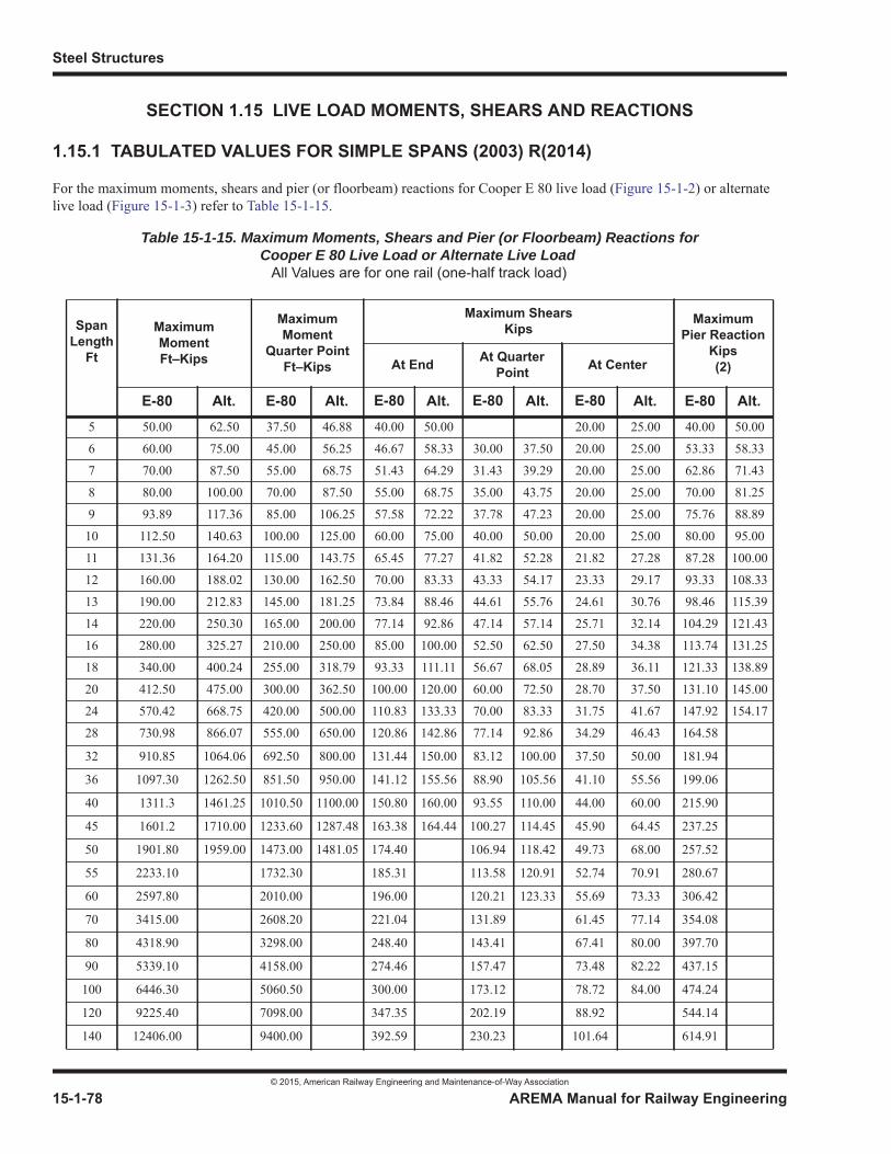
Steel Structures
© 2015, American Railway Engineering and Maintenance-of-Way Association
15-1-78 AREMA Manual for Railway Engineering
SECTION 1.15 LIVE LOAD MOMENTS, SHEARS AND REACTIONS
1.15.1 TABULATED VALUES FOR SIMPLE SPANS (2003) R(2014)
For the maximum moments, shears and pier (or floorbeam) reactions for Cooper E 80 live load (Figure 15-1-2) or alternate live load (Figure 15-1-3) refer to Table 15-1-15.
Table 15-1-15. Maximum Moments, Shears and Pier (or Floorbeam) Reactions for Cooper E 80 Live Load or Alternate Live Load
All Values are for one rail (one-half track load)
SpanLength
Ft
MaximumMomentFt–Kips
MaximumMoment
Quarter PointFt–Kips
Maximum ShearsKips
MaximumPier Reaction
Kips(2)At End At Quarter
Point At Center
E-80 Alt. E-80 Alt. E-80 Alt. E-80 Alt. E-80 Alt. E-80 Alt.5 50.00 62.50 37.50 46.88 40.00 50.00 20.00 25.00 40.00 50.00
6 60.00 75.00 45.00 56.25 46.67 58.33 30.00 37.50 20.00 25.00 53.33 58.33
7 70.00 87.50 55.00 68.75 51.43 64.29 31.43 39.29 20.00 25.00 62.86 71.43
8 80.00 100.00 70.00 87.50 55.00 68.75 35.00 43.75 20.00 25.00 70.00 81.25
9 93.89 117.36 85.00 106.25 57.58 72.22 37.78 47.23 20.00 25.00 75.76 88.89
10 112.50 140.63 100.00 125.00 60.00 75.00 40.00 50.00 20.00 25.00 80.00 95.00
11 131.36 164.20 115.00 143.75 65.45 77.27 41.82 52.28 21.82 27.28 87.28 100.00
12 160.00 188.02 130.00 162.50 70.00 83.33 43.33 54.17 23.33 29.17 93.33 108.33
13 190.00 212.83 145.00 181.25 73.84 88.46 44.61 55.76 24.61 30.76 98.46 115.39
14 220.00 250.30 165.00 200.00 77.14 92.86 47.14 57.14 25.71 32.14 104.29 121.43
16 280.00 325.27 210.00 250.00 85.00 100.00 52.50 62.50 27.50 34.38 113.74 131.25
18 340.00 400.24 255.00 318.79 93.33 111.11 56.67 68.05 28.89 36.11 121.33 138.89
20 412.50 475.00 300.00 362.50 100.00 120.00 60.00 72.50 28.70 37.50 131.10 145.00
24 570.42 668.75 420.00 500.00 110.83 133.33 70.00 83.33 31.75 41.67 147.92 154.17
28 730.98 866.07 555.00 650.00 120.86 142.86 77.14 92.86 34.29 46.43 164.58
32 910.85 1064.06 692.50 800.00 131.44 150.00 83.12 100.00 37.50 50.00 181.94
36 1097.30 1262.50 851.50 950.00 141.12 155.56 88.90 105.56 41.10 55.56 199.06
40 1311.3 1461.25 1010.50 1100.00 150.80 160.00 93.55 110.00 44.00 60.00 215.90
45 1601.2 1710.00 1233.60 1287.48 163.38 164.44 100.27 114.45 45.90 64.45 237.25
50 1901.80 1959.00 1473.00 1481.05 174.40 106.94 118.42 49.73 68.00 257.52
55 2233.10 1732.30 185.31 113.58 120.91 52.74 70.91 280.67
60 2597.80 2010.00 196.00 120.21 123.33 55.69 73.33 306.42
70 3415.00 2608.20 221.04 131.89 61.45 77.14 354.08
80 4318.90 3298.00 248.40 143.41 67.41 80.00 397.70
90 5339.10 4158.00 274.46 157.47 73.48 82.22 437.15
100 6446.30 5060.50 300.00 173.12 78.72 84.00 474.24
120 9225.40 7098.00 347.35 202.19 88.92 544.14
140 12406.00 9400.00 392.59 230.23 101.64 614.91
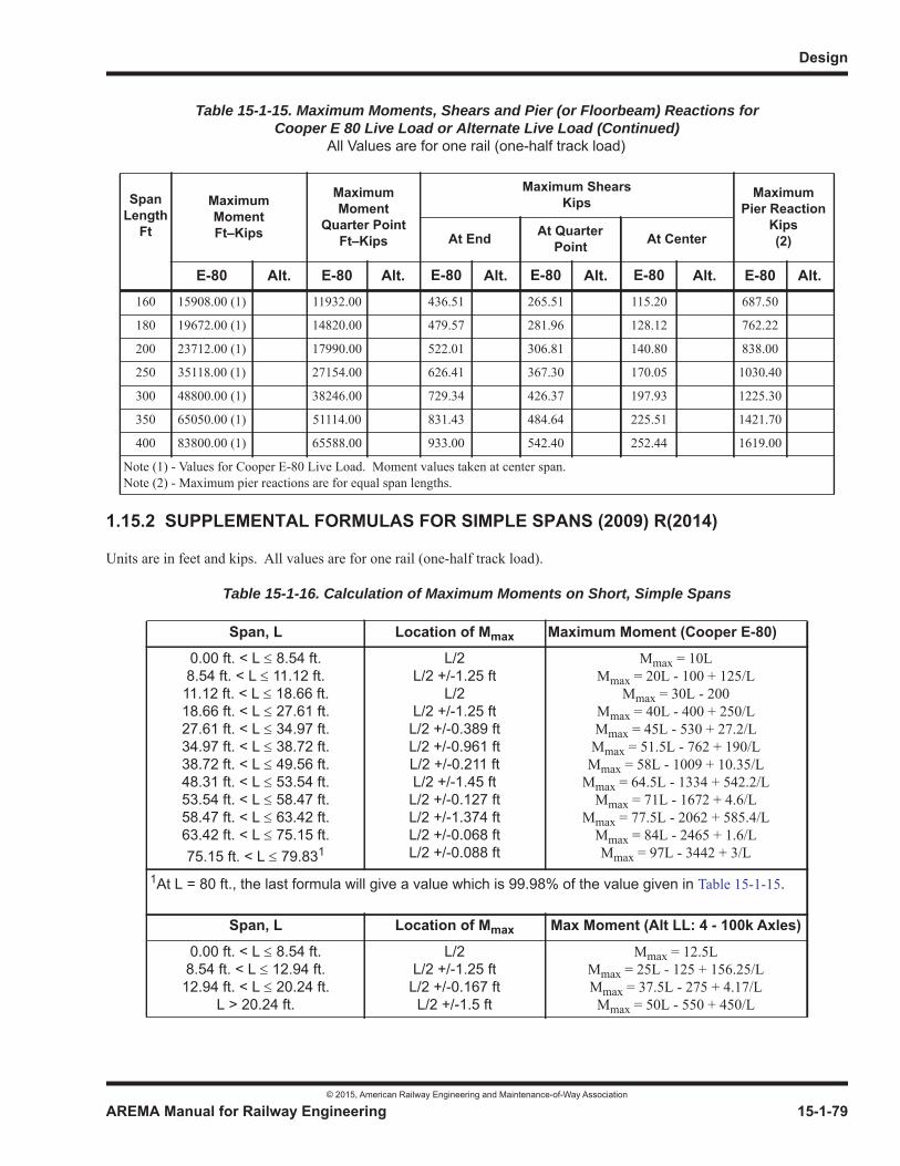
Design
© 2015, American Railway Engineering and Maintenance-of-Way Association
AREMA Manual for Railway Engineering 15-1-79
1
3
4
1.15.2 SUPPLEMENTAL FORMULAS FOR SIMPLE SPANS (2009) R(2014)
Units are in feet and kips. All values are for one rail (one-half track load).
Table 15-1-16. Calculation of Maximum Moments on Short, Simple Spans
160 15908.00 (1) 11932.00 436.51 265.51 115.20 687.50
180 19672.00 (1) 14820.00 479.57 281.96 128.12 762.22
200 23712.00 (1) 17990.00 522.01 306.81 140.80 838.00
250 35118.00 (1) 27154.00 626.41 367.30 170.05 1030.40
300 48800.00 (1) 38246.00 729.34 426.37 197.93 1225.30
350 65050.00 (1) 51114.00 831.43 484.64 225.51 1421.70
400 83800.00 (1) 65588.00 933.00 542.40 252.44 1619.00
Note (1) - Values for Cooper E-80 Live Load. Moment values taken at center span.Note (2) - Maximum pier reactions are for equal span lengths.
Span, L Location of Mmax Maximum Moment (Cooper E-80)0.00 ft. < L 8.54 ft.8.54 ft. < L 11.12 ft.11.12 ft. < L 18.66 ft.18.66 ft. < L 27.61 ft.27.61 ft. < L 34.97 ft.34.97 ft. < L 38.72 ft.38.72 ft. < L 49.56 ft.48.31 ft. < L 53.54 ft.53.54 ft. < L 58.47 ft.58.47 ft. < L 63.42 ft.63.42 ft. < L 75.15 ft.75.15 ft. < L 79.831
L/2L/2 +/-1.25 ft
L/2L/2 +/-1.25 ftL/2 +/-0.389 ftL/2 +/-0.961 ftL/2 +/-0.211 ftL/2 +/-1.45 ftL/2 +/-0.127 ftL/2 +/-1.374 ftL/2 +/-0.068 ftL/2 +/-0.088 ft
Mmax = 10LMmax = 20L - 100 + 125/L
Mmax = 30L - 200Mmax = 40L - 400 + 250/LMmax = 45L - 530 + 27.2/LMmax = 51.5L - 762 + 190/LMmax = 58L - 1009 + 10.35/L
Mmax = 64.5L - 1334 + 542.2/LMmax = 71L - 1672 + 4.6/L
Mmax = 77.5L - 2062 + 585.4/LMmax = 84L - 2465 + 1.6/LMmax = 97L - 3442 + 3/L
1At L = 80 ft., the last formula will give a value which is 99.98% of the value given in Table 15-1-15.
Span, L Location of Mmax Max Moment (Alt LL: 4 - 100k Axles)0.00 ft. < L 8.54 ft.
8.54 ft. < L 12.94 ft.12.94 ft. < L 20.24 ft.
L > 20.24 ft.
L/2L/2 +/-1.25 ftL/2 +/-0.167 ftL/2 +/-1.5 ft
Mmax = 12.5LMmax = 25L - 125 + 156.25/LMmax = 37.5L - 275 + 4.17/LMmax = 50L - 550 + 450/L
Table 15-1-15. Maximum Moments, Shears and Pier (or Floorbeam) Reactions for Cooper E 80 Live Load or Alternate Live Load (Continued)
All Values are for one rail (one-half track load)
SpanLength
Ft
MaximumMomentFt–Kips
MaximumMoment
Quarter PointFt–Kips
Maximum ShearsKips
MaximumPier Reaction
Kips(2)At End At Quarter
Point At Center
E-80 Alt. E-80 Alt. E-80 Alt. E-80 Alt. E-80 Alt. E-80 Alt.
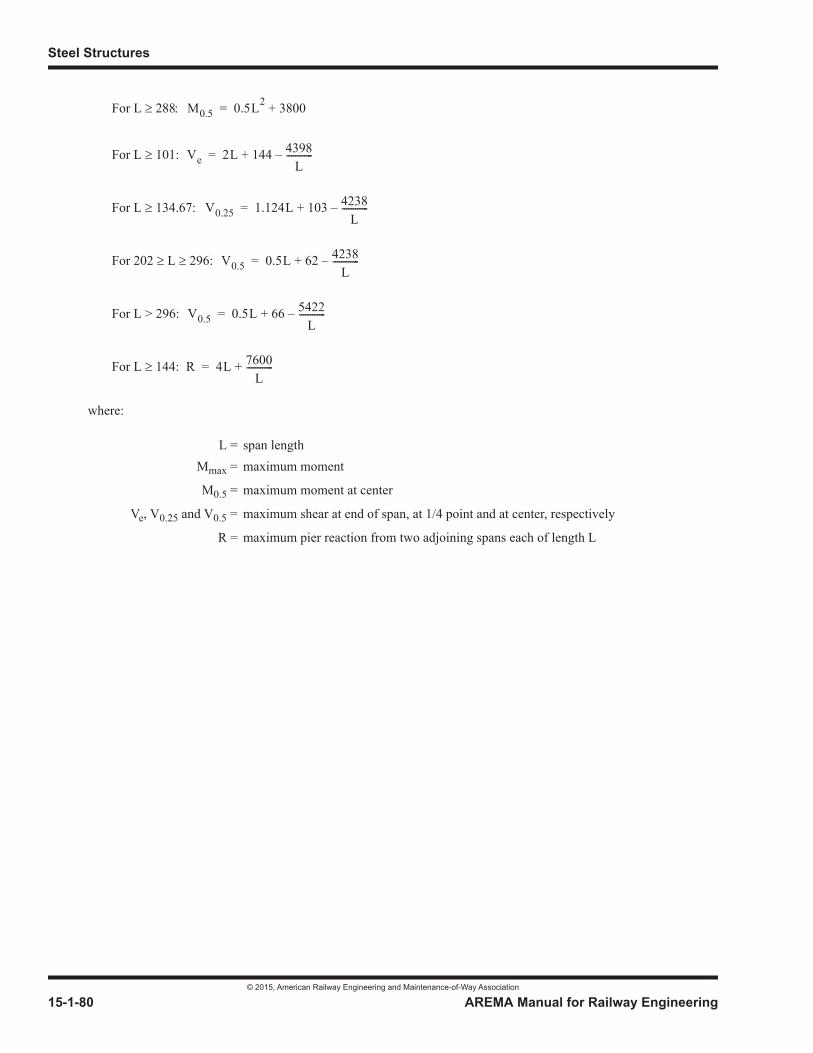
Steel Structures
© 2015, American Railway Engineering and Maintenance-of-Way Association
15-1-80 AREMA Manual for Railway Engineering
For L 288
For L 101:
For L 134.67:
For 202 L 296:
For L > 296:
For L 144:
where:
L = span lengthMmax = maximum moment
M0.5 = maximum moment at center
Ve, V0.25 and V0.5 = maximum shear at end of span, at 1/4 point and at center, respectively
R = maximum pier reaction from two adjoining spans each of length L
M0.5 0.5L2 3800+=
Ve 2L 144 4398L
------------–+=
V0.25 1.124L 103 4238L
------------–+=
V0.5 0.5L 62 4238L
------------–+=
V0.5 0.5L 66 5422L
------------–+=
R 4L 7600L
------------+=
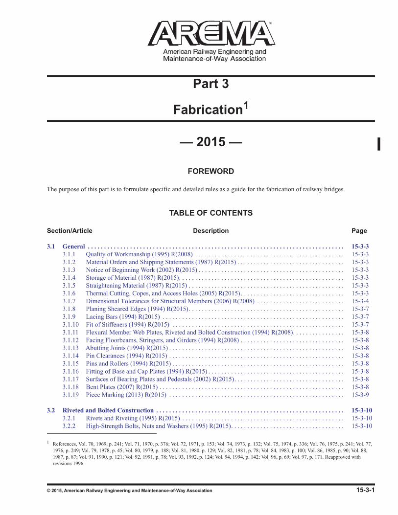
© 2015, American Railway Engineering and Maintenance-of-Way Association 15-3-1
1
3
15Part 3
Fabrication1
— 2015 —
FOREWORD
The purpose of this part is to formulate specific and detailed rules as a guide for the fabrication of railway bridges.
TABLE OF CONTENTS
Section/Article Description Page
3.1 General . . . . . . . . . . . . . . . . . . . . . . . . . . . . . . . . . . . . . . . . . . . . . . . . . . . . . . . . . . . . . . . . . . . . . . . . . . . . . . . 15-3-33.1.1 Quality of Workmanship (1995) R(2008) . . . . . . . . . . . . . . . . . . . . . . . . . . . . . . . . . . . . . . . . . . . . . . 15-3-33.1.2 Material Orders and Shipping Statements (1987) R(2015) . . . . . . . . . . . . . . . . . . . . . . . . . . . . . . . . . 15-3-33.1.3 Notice of Beginning Work (2002) R(2015) . . . . . . . . . . . . . . . . . . . . . . . . . . . . . . . . . . . . . . . . . . . . . 15-3-33.1.4 Storage of Material (1987) R(2015). . . . . . . . . . . . . . . . . . . . . . . . . . . . . . . . . . . . . . . . . . . . . . . . . . . 15-3-33.1.5 Straightening Material (1987) R(2015) . . . . . . . . . . . . . . . . . . . . . . . . . . . . . . . . . . . . . . . . . . . . . . . . 15-3-33.1.6 Thermal Cutting, Copes, and Access Holes (2005) R(2015) . . . . . . . . . . . . . . . . . . . . . . . . . . . . . . . . 15-3-33.1.7 Dimensional Tolerances for Structural Members (2006) R(2008) . . . . . . . . . . . . . . . . . . . . . . . . . . . 15-3-43.1.8 Planing Sheared Edges (1994) R(2015). . . . . . . . . . . . . . . . . . . . . . . . . . . . . . . . . . . . . . . . . . . . . . . . 15-3-73.1.9 Lacing Bars (1994) R(2015) . . . . . . . . . . . . . . . . . . . . . . . . . . . . . . . . . . . . . . . . . . . . . . . . . . . . . . . . 15-3-73.1.10 Fit of Stiffeners (1994) R(2015) . . . . . . . . . . . . . . . . . . . . . . . . . . . . . . . . . . . . . . . . . . . . . . . . . . . . . 15-3-73.1.11 Flexural Member Web Plates, Riveted and Bolted Construction (1994) R(2008). . . . . . . . . . . . . . . . 15-3-83.1.12 Facing Floorbeams, Stringers, and Girders (1994) R(2008) . . . . . . . . . . . . . . . . . . . . . . . . . . . . . . . . 15-3-83.1.13 Abutting Joints (1994) R(2015) . . . . . . . . . . . . . . . . . . . . . . . . . . . . . . . . . . . . . . . . . . . . . . . . . . . . . . 15-3-83.1.14 Pin Clearances (1994) R(2015) . . . . . . . . . . . . . . . . . . . . . . . . . . . . . . . . . . . . . . . . . . . . . . . . . . . . . . 15-3-83.1.15 Pins and Rollers (1994) R(2015) . . . . . . . . . . . . . . . . . . . . . . . . . . . . . . . . . . . . . . . . . . . . . . . . . . . . . 15-3-83.1.16 Fitting of Base and Cap Plates (1994) R(2015) . . . . . . . . . . . . . . . . . . . . . . . . . . . . . . . . . . . . . . . . . . 15-3-83.1.17 Surfaces of Bearing Plates and Pedestals (2002) R(2015). . . . . . . . . . . . . . . . . . . . . . . . . . . . . . . . . . 15-3-83.1.18 Bent Plates (2007) R(2015) . . . . . . . . . . . . . . . . . . . . . . . . . . . . . . . . . . . . . . . . . . . . . . . . . . . . . . . . . 15-3-83.1.19 Piece Marking (2013) R(2015) . . . . . . . . . . . . . . . . . . . . . . . . . . . . . . . . . . . . . . . . . . . . . . . . . . . . . . 15-3-9
3.2 Riveted and Bolted Construction . . . . . . . . . . . . . . . . . . . . . . . . . . . . . . . . . . . . . . . . . . . . . . . . . . . . . . . . . . 15-3-103.2.1 Rivets and Riveting (1995) R(2015) . . . . . . . . . . . . . . . . . . . . . . . . . . . . . . . . . . . . . . . . . . . . . . . . . . 15-3-103.2.2 High-Strength Bolts, Nuts and Washers (1995) R(2015). . . . . . . . . . . . . . . . . . . . . . . . . . . . . . . . . . . 15-3-10
1 References, Vol. 70, 1969, p. 241; Vol. 71, 1970, p. 376; Vol. 72, 1971, p. 153; Vol. 74, 1973, p. 132; Vol. 75, 1974, p. 336; Vol. 76, 1975, p. 241; Vol. 77, 1976, p. 249; Vol. 79, 1978, p. 45; Vol. 80, 1979, p. 188; Vol. 81, 1980, p. 129; Vol. 82, 1981, p. 78; Vol. 84, 1983, p. 100; Vol. 86, 1985, p. 90; Vol. 88, 1987, p. 87; Vol. 91, 1990, p. 121; Vol. 92, 1991, p. 78; Vol. 93, 1992, p. 124; Vol. 94, 1994, p. 142; Vol. 96, p. 69; Vol. 97, p. 171. Reapproved with revisions 1996.
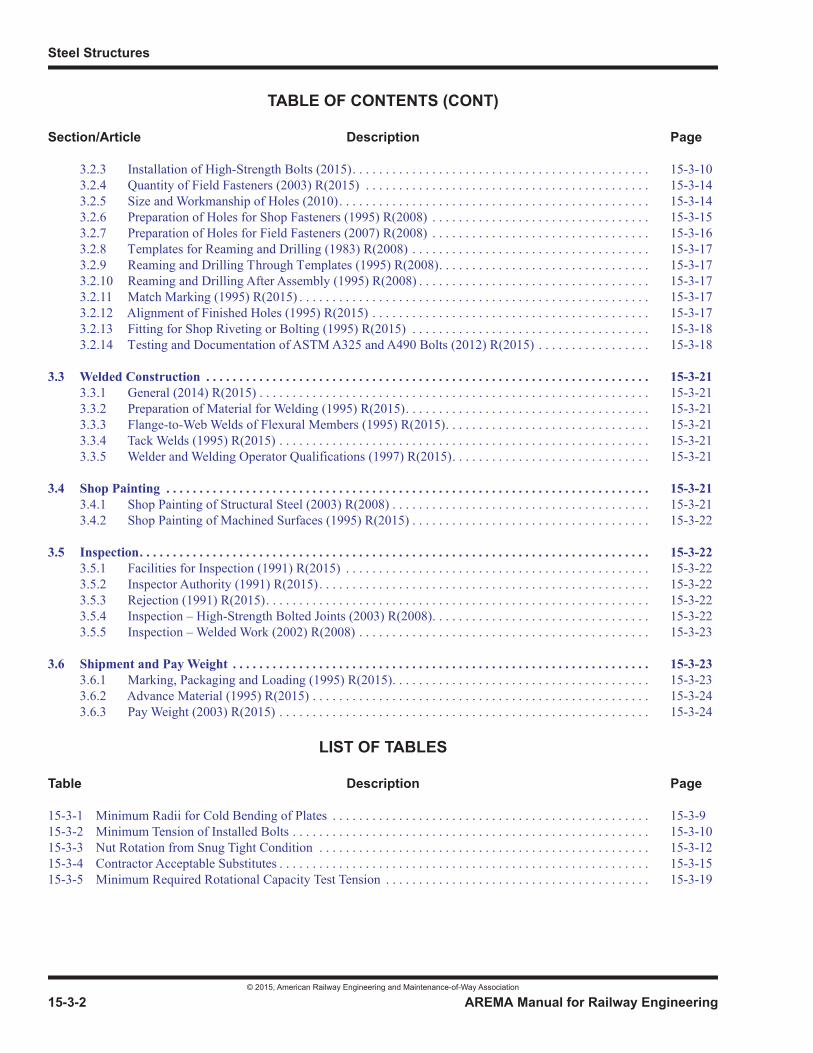
Steel Structures
© 2015, American Railway Engineering and Maintenance-of-Way Association
15-3-2 AREMA Manual for Railway Engineering
TABLE OF CONTENTS (CONT)
Section/Article Description Page
3.2.3 Installation of High-Strength Bolts (2015). . . . . . . . . . . . . . . . . . . . . . . . . . . . . . . . . . . . . . . . . . . . . 15-3-103.2.4 Quantity of Field Fasteners (2003) R(2015) . . . . . . . . . . . . . . . . . . . . . . . . . . . . . . . . . . . . . . . . . . . 15-3-143.2.5 Size and Workmanship of Holes (2010). . . . . . . . . . . . . . . . . . . . . . . . . . . . . . . . . . . . . . . . . . . . . . . 15-3-143.2.6 Preparation of Holes for Shop Fasteners (1995) R(2008) . . . . . . . . . . . . . . . . . . . . . . . . . . . . . . . . . 15-3-153.2.7 Preparation of Holes for Field Fasteners (2007) R(2008) . . . . . . . . . . . . . . . . . . . . . . . . . . . . . . . . . 15-3-163.2.8 Templates for Reaming and Drilling (1983) R(2008) . . . . . . . . . . . . . . . . . . . . . . . . . . . . . . . . . . . . 15-3-173.2.9 Reaming and Drilling Through Templates (1995) R(2008). . . . . . . . . . . . . . . . . . . . . . . . . . . . . . . . 15-3-173.2.10 Reaming and Drilling After Assembly (1995) R(2008) . . . . . . . . . . . . . . . . . . . . . . . . . . . . . . . . . . . 15-3-173.2.11 Match Marking (1995) R(2015) . . . . . . . . . . . . . . . . . . . . . . . . . . . . . . . . . . . . . . . . . . . . . . . . . . . . . 15-3-173.2.12 Alignment of Finished Holes (1995) R(2015) . . . . . . . . . . . . . . . . . . . . . . . . . . . . . . . . . . . . . . . . . . 15-3-173.2.13 Fitting for Shop Riveting or Bolting (1995) R(2015) . . . . . . . . . . . . . . . . . . . . . . . . . . . . . . . . . . . . 15-3-183.2.14 Testing and Documentation of ASTM A325 and A490 Bolts (2012) R(2015) . . . . . . . . . . . . . . . . . 15-3-18
3.3 Welded Construction . . . . . . . . . . . . . . . . . . . . . . . . . . . . . . . . . . . . . . . . . . . . . . . . . . . . . . . . . . . . . . . . . . . 15-3-213.3.1 General (2014) R(2015) . . . . . . . . . . . . . . . . . . . . . . . . . . . . . . . . . . . . . . . . . . . . . . . . . . . . . . . . . . . 15-3-213.3.2 Preparation of Material for Welding (1995) R(2015). . . . . . . . . . . . . . . . . . . . . . . . . . . . . . . . . . . . . 15-3-213.3.3 Flange-to-Web Welds of Flexural Members (1995) R(2015). . . . . . . . . . . . . . . . . . . . . . . . . . . . . . . 15-3-213.3.4 Tack Welds (1995) R(2015) . . . . . . . . . . . . . . . . . . . . . . . . . . . . . . . . . . . . . . . . . . . . . . . . . . . . . . . . 15-3-213.3.5 Welder and Welding Operator Qualifications (1997) R(2015). . . . . . . . . . . . . . . . . . . . . . . . . . . . . . 15-3-21
3.4 Shop Painting . . . . . . . . . . . . . . . . . . . . . . . . . . . . . . . . . . . . . . . . . . . . . . . . . . . . . . . . . . . . . . . . . . . . . . . . . 15-3-213.4.1 Shop Painting of Structural Steel (2003) R(2008) . . . . . . . . . . . . . . . . . . . . . . . . . . . . . . . . . . . . . . . 15-3-213.4.2 Shop Painting of Machined Surfaces (1995) R(2015) . . . . . . . . . . . . . . . . . . . . . . . . . . . . . . . . . . . . 15-3-22
3.5 Inspection. . . . . . . . . . . . . . . . . . . . . . . . . . . . . . . . . . . . . . . . . . . . . . . . . . . . . . . . . . . . . . . . . . . . . . . . . . . . . 15-3-223.5.1 Facilities for Inspection (1991) R(2015) . . . . . . . . . . . . . . . . . . . . . . . . . . . . . . . . . . . . . . . . . . . . . . 15-3-223.5.2 Inspector Authority (1991) R(2015). . . . . . . . . . . . . . . . . . . . . . . . . . . . . . . . . . . . . . . . . . . . . . . . . . 15-3-223.5.3 Rejection (1991) R(2015). . . . . . . . . . . . . . . . . . . . . . . . . . . . . . . . . . . . . . . . . . . . . . . . . . . . . . . . . . 15-3-223.5.4 Inspection – High-Strength Bolted Joints (2003) R(2008). . . . . . . . . . . . . . . . . . . . . . . . . . . . . . . . . 15-3-223.5.5 Inspection – Welded Work (2002) R(2008) . . . . . . . . . . . . . . . . . . . . . . . . . . . . . . . . . . . . . . . . . . . . 15-3-23
3.6 Shipment and Pay Weight . . . . . . . . . . . . . . . . . . . . . . . . . . . . . . . . . . . . . . . . . . . . . . . . . . . . . . . . . . . . . . . 15-3-233.6.1 Marking, Packaging and Loading (1995) R(2015). . . . . . . . . . . . . . . . . . . . . . . . . . . . . . . . . . . . . . . 15-3-233.6.2 Advance Material (1995) R(2015) . . . . . . . . . . . . . . . . . . . . . . . . . . . . . . . . . . . . . . . . . . . . . . . . . . . 15-3-243.6.3 Pay Weight (2003) R(2015) . . . . . . . . . . . . . . . . . . . . . . . . . . . . . . . . . . . . . . . . . . . . . . . . . . . . . . . . 15-3-24
LIST OF TABLES
Table Description Page
15-3-1 Minimum Radii for Cold Bending of Plates . . . . . . . . . . . . . . . . . . . . . . . . . . . . . . . . . . . . . . . . . . . . . . . . 15-3-915-3-2 Minimum Tension of Installed Bolts . . . . . . . . . . . . . . . . . . . . . . . . . . . . . . . . . . . . . . . . . . . . . . . . . . . . . . 15-3-1015-3-3 Nut Rotation from Snug Tight Condition . . . . . . . . . . . . . . . . . . . . . . . . . . . . . . . . . . . . . . . . . . . . . . . . . . 15-3-1215-3-4 Contractor Acceptable Substitutes . . . . . . . . . . . . . . . . . . . . . . . . . . . . . . . . . . . . . . . . . . . . . . . . . . . . . . . . 15-3-1515-3-5 Minimum Required Rotational Capacity Test Tension . . . . . . . . . . . . . . . . . . . . . . . . . . . . . . . . . . . . . . . . 15-3-19
Fabrication
© 2015, American Railway Engineering and Maintenance-of-Way Association
AREMA Manual for Railway Engineering 15-3-3
1
3
4
SECTION 3.1 GENERAL
3.1.1 QUALITY OF WORKMANSHIP (1995) R(2008)
a. Structural steel fabricators shall be certified for the type of structure being fabricated under the AISC Quality Certification Program (SBR - Simple Steel Bridge Structures or CBR - Major Steel Bridges [all bridge structures other than unspliced rolled beam bridges]) or another suitable program as determined by the Engineer. Evidence of certification shall be submitted to the Engineer for his approval before beginning any work.
b. Structural steel fabricators of Fracture Critical Members shall be certified under the AISC Quality Certification Program, with a Fracture Critical Endorsement (F) or another suitable program as determined by the Engineer. The fabricator shall also meet the additional requirements for Fracture Critical Members specified in Part 1, Design,Section 1.14, Fracture Critical Members.
c. The workmanship and finish shall be equal to the best general practice in modern bridge shops.
3.1.2 MATERIAL ORDERS AND SHIPPING STATEMENTS (1987) R(2015)
The Contractor shall furnish to the Engineer as many copies of material orders and shipping statements as the Engineer may require. The weights of the individual members shall be shown on the statements.
3.1.3 NOTICE OF BEGINNING WORK (2002) R(2015)
The Contractor shall give the Engineer ample written notice of the beginning of work in the shop, in order that inspection may be provided. Work shall not be done in the shop before the Engineer has been so notified.
3.1.4 STORAGE OF MATERIAL (1987) R(2015)
Structural material, either plain or fabricated, shall be stored properly above the ground upon platforms, skids, or other supports. It shall be kept free from dirt, grease and other foreign matter, and shall be protected as far as practicable from corrosion.
3.1.5 STRAIGHTENING MATERIAL (1987) R(2015)
Rolled material, before being laid off or worked, shall be straight within the tolerances allowed by ASTM Specification A6. If straightening is necessary, it shall be done by methods which will not adversely affect the behavior of the material.
3.1.6 THERMAL CUTTING, COPES, AND ACCESS HOLES (2005)1 R(2015)
3.1.6.1 Thermal Cutting
a. The steels covered by these recommended practices may be thermally-cut, provided that a smooth surface free from cracks and notches is secured and provided that an accurate profile is secured by the use of a mechanical guide. Freehand cutting shall be done only when specifically approved by the Engineer.
b. Cutting shall be done in such a manner as to avoid cutting inside the prescribed lines. The Surface Roughness value of cut surfaces, as defined in “ASME B46.1-1995 Surface Texture (Surface Roughness, Waviness and Lay), an American National Standard” published by The American Society of Mechanical Engineers, shall not exceed 1,000 in (25 m)
1 See Part 9 Commentary
Steel Structures
© 2015, American Railway Engineering and Maintenance-of-Way Association
15-3-4 AREMA Manual for Railway Engineering
for material up to 4 inches (100 mm) thick and 2,000 in (50 m) for material 4 inches (100 mm) to 8 inches (200 mm) thick. Member ends not subjected to calculated stress may have a surface roughness value up to 2,000 in (50 m).The procedure described below shall be used to correct roughness exceeding the applicable value or occasional notches or gouges. Roughness exceeding the applicable value and occasional notches or gouges not more than 3/16 inch (5 mm) deep, on otherwise satisfactory surfaces, shall be removed by machining or grinding. Cut surfaces and edges shall be left free of adhering slag. Corrections of defects shall be faired to the oxygen-cut surfaces with a slope not exceeding 1 in 10. Defects in oxygen-cut edges shall not be repaired by welding except occasional notches or gouges up to 7/16 inch (11 mm) deep in material up to 4 inches (100 mm) thick if so approved by the Engineer. The procedure for such weld repair shall be subject to the Engineer’s approval, shall ensure sound metal free from cracks, and shall produce a workmanlike finish.
c. Re-entrant corners shall be filleted to a radius of not less than 1 inch (25 mm). The fillet and its contiguous cuts shall meet without offset or cutting past the point of tangency.
d. Edges of built-up beam and girder webs shall be cut to prescribed camber with suitable allowance for shrinkage due to cutting and welding. However, moderate deviation from the specified camber tolerance may be corrected by a carefully supervised application of heat.
3.1.6.2 Copes and Access Holes
a. The re-entrant corners of copes shall be shaped with a radius of not less than 1 inch (25 mm) with a smooth transition that meets the adjacent edges without offset or cutting past the point of tangency.
b. In hot rolled shapes and built up shapes all beam copes and weld access holes shall be shaped free of notches or sharp re-entrant corners, except when web-to flange fillet welds are used on built-up shapes access holes are permitted to terminate perpendicular to the flange. Thermal cut edges shall meet the requirements of Paragraph 3.2.2 of AWS D1.5.
c. The thermal cut surfaces of holes and re-entrant cuts in primary members and their connections shall be ground to bright metal. For ASTM A6 Group 4 and 5 shapes and built-up shapes with web material thickness greater than 1-1/2 inch (38 mm), the thermal cut surfaces shall be inspected by either magnetic particle or dye-penetrant methods. If the curved transition portion of holes and beam copes are formed by predrilled or sawed holes, that portion of the hole or cope need not be ground. Unless specified by the Engineer, holes and copes in other members need not be ground nor dye-penetrant or magnetic-particle inspected.
d. All weld access holes required to facilitate welding operations shall have a length from the toe of the weld preparation of not less than 1-1/2 times the thickness of the material in which the hole is made. The height of the access hole shall be adequate for the deposition of sound weld metal in the adjacent plates and shall provide clearance for the weld tabs for the weld in the material in which the hole is made, but shall not be less than the thickness of the material.
3.1.7 DIMENSIONAL TOLERANCES FOR STRUCTURAL MEMBERS (2006) R(2008)
3.1.7.1 General Provisions
a. Members and parts of members shall be straight, true to line, and free from twists and bends. In determining acceptability under these general requirements, the tolerances stated hereinafter shall be applied as indicated. When more accurate conformance to detailed dimensions is required for any member or part of a member, it shall be specifically stated on the contract plans.
b. Surfaces intended to be in a common plane at connections, joints, splices and bearings shall have no offset greater than 1/8 inch unless properly accommodated by fillers.
c. For rolled shapes or plates, the tolerance for any dimension shall conform with the requirements of ASTM A6 except as otherwise shown on the contract drawings.

Fabrication
© 2015, American Railway Engineering and Maintenance-of-Way Association
AREMA Manual for Railway Engineering 15-3-5
1
3
4
d. The tolerances stated hereinafter have been established to apply primarily to members fabricated by welding. Riveted and bolted members shall be well within these specified tolerances, as shall rolled members to the extent not excepted by paragraph c above.
e. Allowable deviations.
(1) Deviation from detailed length:
(2) Deviation from detailed straightness or curvature, that is, sweep or deviation from camber:
±1/16 inch
or
±1/4 inch, whichever is greater.
(3) Deviation from parallelism between corresponding elements of the same part at different cross-sections along the length of the member (i.e. twist):
For box sections 1/16 inch in 12 inches bevel
For I sections 1/8 inch in 12 inches bevel
(4) Deviation from detailed depth or width, measured at the centerline of each web or flange:
where:
(5) Out of square for box-shaped members. The deviation of parts on opposite sides of a member measured transverse to the principal axis of the cross-section shall not exceed:
3/16 inch +
For members with ends milled for bearing and members with end connection angles faced ±1/32 inchFor framed members not milled or faced: Lengths of 30 feet and under ±1/16 inch Lengths over 30 feet ±1/8 inchFor other members ±1/4 inch
D = the dimension, inch, being considered
No. of feet of length between points10
--------------------------------------------------------------------------------------
No. of feet of length between sections10
-------------------------------------------------------------------------------------------
No. of feet of length between sections10
-------------------------------------------------------------------------------------------
1 8 inch D500---------+
D1000------------
Steel Structures
© 2015, American Railway Engineering and Maintenance-of-Way Association
15-3-6 AREMA Manual for Railway Engineering
where:
(6) Lateral deviation between the centerline of flanges measured transverse to the theoretical center line of web of I-shaped members at splice points and contact points of connection shall not exceed:
3/16 inch +
where:
(7) Combined warpage and tilt of flange at any cross section of welded I-shaped beams or girders shall be determined by measuring the offset at toe of flange from a line normal to the plane of the web through the intersection of the centerline of web with the outside surface of the flange plate. This offset shall not exceed 1/100 of total width of flange or 1/4 inch, whichever is greater, at any point along the member and 1/32 inch at any bearing.
(8) The tolerances for out of flatness of seats and bases shall be as specified in Article 5.9.6.
(9) Deviation from flatness or detailed curvature of panels of plate elements shall be determined by measuring offsets perpendicular to a template, edge having the detailed straightness or curvature and a length not less than the smaller of d1 or d2 as defined below and not more than 1.5 times the smaller of d1 or d2. The measurements shall be taken between points of contact of the template edge with the plate. The template edge may be placed anywhere within the panel of plate. The maximum offset shall not exceed the applicable values computed as follows:
(a) For girder webs without intermediate stiffeners but not greater than 0.75 t.
(b) For all stiffened plate elements but not greater than 1.5 t.
where:
(10) Deviation from detailed position of secondary parts and connections. (The detailed position is defined as the detailed distance from the member connection, centerline of bearing, or other primary working point or line):
(a) For each secondary part not used for connection of other members except bearing stiffeners. (That is, a part such as a plain stiffener plate or bar.) ±1/4 inch.
D = the nominal distance, inch, between the opposite sides.
D = the nominal distance, inch, between the flanges
d = the least dimension, inch, of:d1 the maximum transverse distance between longitudinal flanges edges or stiffeners, inch,d2 the maximum longitudinal distance between transverse edges or stiffeners, inch, ord3 the clear distance between points of contact of the template with the plate or web, inch
t = the minimum thickness of the plate within the panel, inch
D1000------------
d
200 t---------------
d100 t---------------
Fabrication
© 2015, American Railway Engineering and Maintenance-of-Way Association
AREMA Manual for Railway Engineering 15-3-7
1
3
4
(b) For each secondary part used for connection of secondary members, and also for bearing stiffeners. (That is, a part used for connections in which the holes would be permitted to be punched full size if the connections were bolted.) ±1/8 inch.
(11) Deviations from full surface contact:
(a) At least 70% of the surfaces specified to be in bearing contact shall have the contact surfaces within 0.005 inch of each other. No remaining portion of the surfaces specified to be in bearing contact shall have a separation exceeding 0.03 inch. Any element of the main material which is composed of multiple elements shall have a minimum of 60% of its bearing area in contact.
(b) Contact surfaces specified to be prepared by milling, grinding, or planing shall have a surface roughness value not to exceed 250 in (ANSI/ASME) B46.1 Surface Texture.
3.1.7.2 Special Provisions for Trusses and Viaduct-Tower Main Members
a. Abutting joints of compression members which have been faced for bearing, when assembled, shall conform to Article 3.1.7.1e(11).
b. For member connections or splices, whether at joints or between joints, the clearance between the in-to-in dimension of the gusset plates or splice plates and the out-to-out dimensions of the entering member shall not exceed 3/16 inch or as otherwise indicated by the Engineer for joints with thick or multiple gusset plates, long diaphragms, or other special framing conditions.
c. The use of squaring-up diaphragms may be necessary to meet the tolerances established in Article 3.1.7.1 and this Article. Design details of squaring-up diaphragms and any design restrictions on their use shall be shown on the design plans. Unless designated otherwise, their use will be optional with the contractor. All squaring-up diaphragms shall be shown on the shop drawings.
3.1.8 PLANING SHEARED EDGES (1994)1 R(2015)
Sheared edges of ASTM A36 main material over 5/8 inch thick and all high-strength main material shall be planed to a depth of 1/4 inch. Web plates and pin plates (regardless of thickness) of pin connected tension members shall be universal mill platesor shall have edges planed 1/4 inch and the ends back of pins planed 1/4 inch.
3.1.9 LACING BARS (1994) R(2015)
The ends of lacing bars shall be rounded unless otherwise required.
3.1.10 FIT OF STIFFENERS (1994) R(2015)
a. The ends of stiffeners on flexural members at points of bearing, as defined in Part 1, Design, Article 1.7.7, shall be milled or ground to bear against the flange, or shall be welded to the flange with a full penetration groove weld. Refer to Article 3.1.7.1e(7) and Article 3.1.7.1e(11) for combined warpage and tilt of flange and deviation from full surface contact.
b. The fit of intermediate stiffener ends against the flange shall be such as to exclude water after being painted. The exception is for welded flexural members where the ends of stiffeners adjacent to the tension flange may be cut back to comply with the requirements of Part 1, Design, Article 1.10.4.
c. Fillers and splice plates under angle stiffeners shall be made to fit within 1/4 inch at each end.
1 See Part 9 Commentary

Steel Structures
© 2015, American Railway Engineering and Maintenance-of-Way Association
15-3-8 AREMA Manual for Railway Engineering
3.1.11 FLEXURAL MEMBER WEB PLATES, RIVETED AND BOLTED CONSTRUCTION (1994) R(2008)
a. The edges of web plates of riveted or bolted flexural members that have no cover plates shall not be more than 1/8 inch above or below the backs of the top flange angles. Web plates of such members with cover plates may be 1/2 inch less in width than the distance back to back of flange angles.
b. In riveted or bolted splices of web plates there shall not be more than 3/8 inch opening between the plates.
3.1.12 FACING FLOORBEAMS, STRINGERS, AND GIRDERS (1994) R(2008)
Floorbeams, stringers, and girders having end connection angles shall be made to exact length with tolerance as allowed in Article 3.1.7.1e(1). If facing is necessary, the thickness of the end connection angles shall not be reduced more than 1/8 inch at any point.
3.1.13 ABUTTING JOINTS (1994) R(2015)
Where splice material at joints and splices in compression members or girder flanges is designed to transmit force as specifiedin Part 1, Design, Article 1.5.9d, all main material at that joint or splice shall be milled and brought to an even bearing in one plane across the end of each abutting piece at the joint or splice. When so specified on the drawings, this requirement shall alsoapply to tension members. When the abutting surfaces are not milled, the opening shall not be more than 1/4 inch. Note: Refer to Article 3.1.7.1e(11) for deviations from full surface contact.
3.1.14 PIN CLEARANCES (1994) R(2015)
The difference in diameter between the pin and the pin hole shall be 1/50 inch for pins up to 5 inches diameter, and 1/32 inch for larger pins.
3.1.15 PINS AND ROLLERS (1994) R(2015)
Pins and rollers shall be turned accurately to gage and shall be straight, smooth, and free from flaws. For additional information on pins and rollers see Part 5.
3.1.16 FITTING OF BASE AND CAP PLATES (1994) R(2015)
Both top and bottom surfaces of base and cap plates of columns shall be planed or straightened and the parts of the members in contact with them faced to fit. Connection angles for base plates and cap plates shall be connected to compression members before the members are faced. Note: Refer to Article 3.1.7.1e(11) for deviations from full surface contact.
3.1.17 SURFACES OF BEARING PLATES AND PEDESTALS (2002) R(2015)
Refer to Part 5.
3.1.18 BENT PLATES (2007)1 R(2015)
a. Bending procedures shall be such that no cracking of the plate occurs. Large dents or upsets shall be avoided. All bends shall receive at least visual inspection. Material that does not form satisfactorily when fabricated in accordance with the requirements of this Article shall be subject to rejection.
b. The bend radius and the radius of the male die should be as liberal as the finished part will permit. The width across the shoulders of the female die should be at least 8 times the plate thickness for ASTM A36/A36M and ASTM
1 See Part 9 Commentary
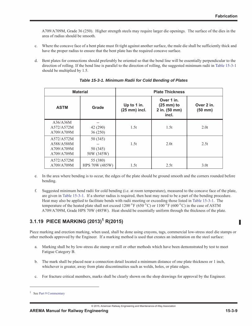
Fabrication
© 2015, American Railway Engineering and Maintenance-of-Way Association
AREMA Manual for Railway Engineering 15-3-9
1
3
4
A709/A709M, Grade 36 (250). Higher strength steels may require larger die openings. The surface of the dies in the area of radius should be smooth.
c. Where the concave face of a bent plate must fit tight against another surface, the male die shall be sufficiently thick and have the proper radius to ensure that the bent plate has the required concave surface.
d. Bent plates for connections should preferably be oriented so that the bend line will be essentially perpendicular to the direction of rolling. If the bend line is parallel to the direction of rolling, the suggested minimum radii in Table 15-3-1should be multiplied by 1.5.
Table 15-3-1. Minimum Radii for Cold Bending of Plates
e. In the area where bending is to occur, the edges of the plate should be ground smooth and the corners rounded before bending.
f. Suggested minimum bend radii for cold bending (i.e. at room temperature), measured to the concave face of the plate, are given in Table 15-3-1. If a shorter radius is required, then heat may need to be a part of the bending procedure.Heat may also be applied to facilitate bends with radii meeting or exceeding those listed in Table 15-3-1. The temperature of the heated plate shall not exceed 1200 F (650 C) or 1100 F (600 C) in the case of ASTM A709/A709M, Grade HPS 70W (485W). Heat should be essentially uniform through the thickness of the plate.
3.1.19 PIECE MARKING (2013)1 R(2015)
Piece marking and erection marking, when used, shall be done using crayons, tags, commercial low-stress steel die stamps or other methods approved by the Engineer. If a marking method is used that creates an indentation on the steel surface:
a. Marking shall be by low-stress die stamp or mill or other methods which have been demonstrated by test to meet Fatigue Category B.
b. The mark shall be placed near a connection detail located a minimum distance of one plate thickness or 1 inch, whichever is greater, away from plate discontinuities such as welds, holes, or plate edges.
c. For fracture critical members, marks shall be clearly shown on the shop drawings for approval by the Engineer.
Material Plate Thickness
ASTM Grade Up to 1 in. (25 mm) incl.
Over 1 in. (25 mm) to
2 in. (50 mm) incl.
Over 2 in. (50 mm)
A36/A36MA572/A572MA709/A709M
--42 (290)36 (250)
1.5t 1.5t 2.0t
A572/A572MA588/A588MA709/A709MA709/A709M
50 (345)--
50 (345) 50W (345W)
1.5t 2.0t 2.5t
A572/A572MA709/A709M
55 (380)HPS 70W (485W) 1.5t 2.5t 3.0t
1 See Part 9 Commentary
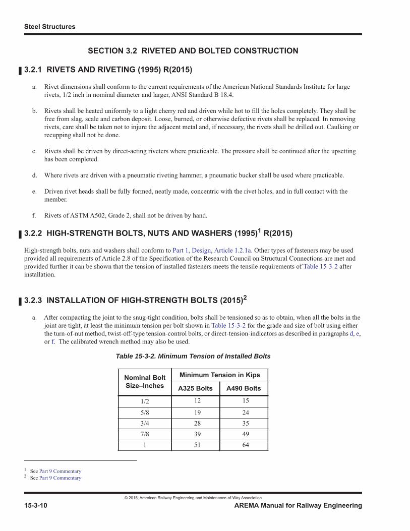
Steel Structures
© 2015, American Railway Engineering and Maintenance-of-Way Association
15-3-10 AREMA Manual for Railway Engineering
SECTION 3.2 RIVETED AND BOLTED CONSTRUCTION
3.2.1 RIVETS AND RIVETING (1995) R(2015)
a. Rivet dimensions shall conform to the current requirements of the American National Standards Institute for large rivets, 1/2 inch in nominal diameter and larger, ANSI Standard B 18.4.
b. Rivets shall be heated uniformly to a light cherry red and driven while hot to fill the holes completely. They shall be free from slag, scale and carbon deposit. Loose, burned, or otherwise defective rivets shall be replaced. In removing rivets, care shall be taken not to injure the adjacent metal and, if necessary, the rivets shall be drilled out. Caulking or recupping shall not be done.
c. Rivets shall be driven by direct-acting riveters where practicable. The pressure shall be continued after the upsetting has been completed.
d. Where rivets are driven with a pneumatic riveting hammer, a pneumatic bucker shall be used where practicable.
e. Driven rivet heads shall be fully formed, neatly made, concentric with the rivet holes, and in full contact with the member.
f. Rivets of ASTM A502, Grade 2, shall not be driven by hand.
3.2.2 HIGH-STRENGTH BOLTS, NUTS AND WASHERS (1995)1 R(2015)
High-strength bolts, nuts and washers shall conform to Part 1, Design, Article 1.2.1a. Other types of fasteners may be used provided all requirements of Article 2.8 of the Specification of the Research Council on Structural Connections are met and provided further it can be shown that the tension of installed fasteners meets the tensile requirements of Table 15-3-2 after installation.
3.2.3 INSTALLATION OF HIGH-STRENGTH BOLTS (2015)2
a. After compacting the joint to the snug-tight condition, bolts shall be tensioned so as to obtain, when all the bolts in the joint are tight, at least the minimum tension per bolt shown in Table 15-3-2 for the grade and size of bolt using either the turn-of-nut method, twist-off-type tension-control bolts, or direct-tension-indicators as described in paragraphs d, e,or f. The calibrated wrench method may also be used.
1 See Part 9 Commentary2 See Part 9 Commentary
Table 15-3-2. Minimum Tension of Installed Bolts
Nominal BoltSize–Inches
Minimum Tension in Kips
A325 Bolts A490 Bolts
1/2 12 15
5/8 19 243/4 28 357/8 39 491 51 64
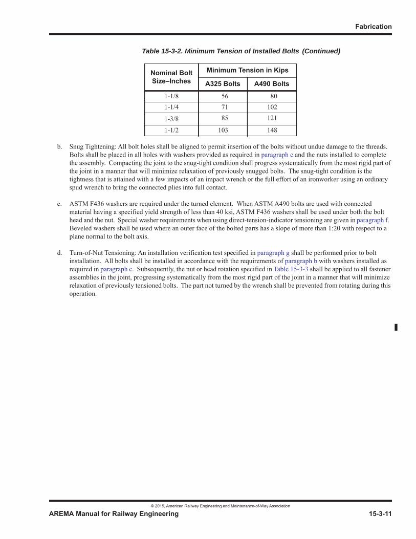
Fabrication
© 2015, American Railway Engineering and Maintenance-of-Way Association
AREMA Manual for Railway Engineering 15-3-11
1
3
4
b. Snug Tightening: All bolt holes shall be aligned to permit insertion of the bolts without undue damage to the threads. Bolts shall be placed in all holes with washers provided as required in paragraph c and the nuts installed to complete the assembly. Compacting the joint to the snug-tight condition shall progress systematically from the most rigid part of the joint in a manner that will minimize relaxation of previously snugged bolts. The snug-tight condition is the tightness that is attained with a few impacts of an impact wrench or the full effort of an ironworker using an ordinary spud wrench to bring the connected plies into full contact.
c. ASTM F436 washers are required under the turned element. When ASTM A490 bolts are used with connected material having a specified yield strength of less than 40 ksi, ASTM F436 washers shall be used under both the bolt head and the nut. Special washer requirements when using direct-tension-indicator tensioning are given in paragraph f.Beveled washers shall be used where an outer face of the bolted parts has a slope of more than 1:20 with respect to a plane normal to the bolt axis.
d. Turn-of-Nut Tensioning: An installation verification test specified in paragraph g shall be performed prior to bolt installation. All bolts shall be installed in accordance with the requirements of paragraph b with washers installed as required in paragraph c. Subsequently, the nut or head rotation specified in Table 15-3-3 shall be applied to all fastener assemblies in the joint, progressing systematically from the most rigid part of the joint in a manner that will minimize relaxation of previously tensioned bolts. The part not turned by the wrench shall be prevented from rotating during this operation.
1-1/8 56 801-1/4 71 102
1-3/8 85 121
1-1/2 103 148
Table 15-3-2. Minimum Tension of Installed Bolts
Nominal BoltSize–Inches
Minimum Tension in Kips
A325 Bolts A490 Bolts
(Continued)
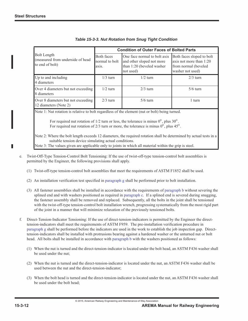
Steel Structures
© 2015, American Railway Engineering and Maintenance-of-Way Association
15-3-12 AREMA Manual for Railway Engineering
e. Twist-Off-Type Tension-Control Bolt Tensioning: If the use of twist-off-type tension-control bolt assemblies is permitted by the Engineer, the following provisions shall apply.
(1) Twist-off-type tension-control bolt assemblies that meet the requirements of ASTM F1852 shall be used.
(2) An installation verification test specified in paragraph g shall be performed prior to bolt installation.
(3) All fastener assemblies shall be installed in accordance with the requirements of paragraph b without severing the splined end and with washers positioned as required in paragraph c. If a splined end is severed during snugging, the fastener assembly shall be removed and replaced. Subsequently, all the bolts in the joint shall be tensioned with the twist-off-type tension-control bolt installation wrench, progressing systematically from the most rigid part of the joint in a manner that will minimize relaxation of the previously tensioned bolts.
f. Direct-Tension-Indicator Tensioning: If the use of direct-tension-indicators is permitted by the Engineer the direct-tension-indicators shall meet the requirements of ASTM F959. The pre-installation verification procedure in paragraph g shall be performed before the indicators are used in the work to establish the job inspection gap. Direct-tension-indicators shall be installed with protrusions bearing against a hardened washer or the unturned nut or bolt head. All bolts shall be installed in accordance with paragraph b with the washers positioned as follows:
(1) When the nut is turned and the direct-tension-indicator is located under the bolt head, an ASTM F436 washer shall be used under the nut;
(2) When the nut is turned and the direct-tension-indicator is located under the nut, an ASTM F436 washer shall be used between the nut and the direct-tension-indicator;
(3) When the bolt head is turned and the direct-tension-indicator is located under the nut, an ASTM F436 washer shall be used under the bolt head;
Table 15-3-3. Nut Rotation from Snug Tight Condition
Bolt Length(measured from underside of head to end of bolt)
Condition of Outer Faces of Bolted PartsBoth faces normal to bolt axis.
One face normal to bolt axis and other sloped not more than 1:20 (beveled washer not used)
Both faces sloped to bolt axis not more than 1:20 from normal (beveled washer not used)
Up to and including 4 diameters
1/3 turn 1/2 turn 2/3 turn
Over 4 diameters but not exceeding 8 diameters
1/2 turn 2/3 turn 5/6 turn
Over 8 diameters but not exceeding 12 diameters (Note 2)
2/3 turn 5/6 turn 1 turn
Note 1: Nut rotation is relative to bolt regardless of the element (nut or bolt) being turned.
For required nut rotation of 1/2 turn or less, the tolerance is minus 0 , plus 30 .For required nut rotation of 2/3 turn or more, the tolerance is minus 0 , plus 45 .
Note 2: Where the bolt length exceeds 12 diameters, the required rotation shall be determined by actual tests in a suitable tension device simulating actual conditions.
Note 3: The values given are applicable only to joints in which all material within the grip is steel.
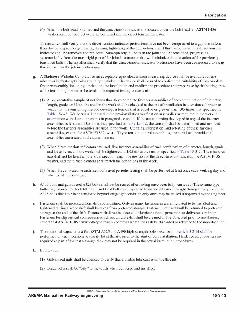
Fabrication
© 2015, American Railway Engineering and Maintenance-of-Way Association
AREMA Manual for Railway Engineering 15-3-13
1
3
4
(4) When the bolt head is turned and the direct-tension-indicator is located under the bolt head, an ASTM F436 washer shall be used between the bolt head and the direct tension indicator.
The installer shall verify that the direct-tension-indicator protrusions have not been compressed to a gap that is less than the job inspection gap during the snug tightening of the connection, and if this has occurred, the direct tension indicator shall be removed and replaced. Subsequently, all bolts in the joint shall be tensioned, progressing systematically from the most rigid part of the joint in a manner that will minimize the relaxation of the previously tensioned bolts. The installer shall verify that the direct-tension-indicator protrusions have been compressed to a gap that is less than the job inspection gap.
g. A Skidmore-Wilhelm Calibrator or an acceptable equivalent tension-measuring device shall be available for use whenever high-strength bolts are being installed. The device shall be used to confirm the suitability of the complete fastener assembly, including lubrication, for installation and confirm the procedure and proper use by the bolting crew of the tensioning method to be used. The required testing consists of:
(1) A representative sample of not fewer than three complete fastener assemblies of each combination of diameter, length, grade, and lot to be used in the work shall be checked at the site of installation in a tension calibrator to verify that the tensioning method develops a tension that is equal to or greater than 1.05 times that specified in Table 15-3-2. Washers shall be used in the pre-installation verification assemblies as required in the work in accordance with the requirements in paragraphs c and f. If the actual tension developed in any of the fastener assemblies is less than 1.05 times that specified in Table 15-3-2, the cause(s) shall be determined and resolved before the fastener assemblies are used in the work. Cleaning, lubrication, and retesting of these fastener assemblies, except for ASTM F1852 twist-off-type tension-control assemblies, are permitted, provided all assemblies are treated in the same manner.
(2) When direct-tension-indicators are used, five fastener assemblies of each combination of diameter, length, grade, and lot to be used in the work shall be tightened to 1.05 times the tension specified in Table 15-3-2. The measured gap shall not be less than the job inspection gap. The position of the direct-tension-indicator, the ASTM F436 washer, and the turned element shall match the conditions in the work.
(3) When the calibrated wrench method is used periodic testing shall be performed at least once each working day and when conditions change.
h. A490 bolts and galvanized A325 bolts shall not be reused after having once been fully tensioned. These same type bolts may be used for both fitting up and final bolting if tightened to no more than snug-tight during fitting up. Other A325 bolts that have been tensioned beyond snug-tight condition only once may be reused if approved by the Engineer.
i. Fasteners shall be protected from dirt and moisture. Only as many fasteners as are anticipated to be installed and tightened during a work shift shall be taken from protected storage. Fasteners not used shall be returned to protected storage at the end of the shift. Fasteners shall not be cleaned of lubricant that is present in as-delivered condition. Fasteners for slip critical connections which accumulate dirt shall be cleaned and relubricated prior to installation, except that ASTM F1852 twist-off-type tension control assemblies shall be discarded or returned to the manufacturer.
j. The rotational-capacity test for ASTM A325 and A490 high-strength bolts described in Article 3.2.14 shall be performed on each rotational-capacity lot at the site prior to the start of bolt installation. Hardened steel washers are required as part of the test although they may not be required in the actual installation procedures.
k. Lubrication:
(1) Galvanized nuts shall be checked to verify that a visible lubricant is on the threads.
(2) Black bolts shall be “oily” to the touch when delivered and installed.

Steel Structures
© 2015, American Railway Engineering and Maintenance-of-Way Association
15-3-14 AREMA Manual for Railway Engineering
(3) Weathered or rusted bolts or nuts, except as noted below in (4), shall be cleaned and relubricated prior to installation. Recleaned or relubricated bolt, nut and washer assemblies shall be retested in accordance with paragraph j prior to installation.
(4) ASTM F1852 twist-off-type tension control assemblies that are not in the as-delivered condition shall not be relubricated in the field, they shall be discarded or returned to the manufacturer.
l. Bolt, nut and washer (when required) combinations as installed shall be from same rotational-capacity lot.
3.2.4 QUANTITY OF FIELD FASTENERS (2003) R(2015)
a. The number of field rivets of each size and length furnished in excess of the nominal number required shall be 10% plus 10.
b. The number of field high-strength bolts of each size and length furnished in excess of the nominal number required shall be 5% plus 10. The number of nuts and washers of each size and type furnished in excess of the nominal number required shall be 5% plus 10.
3.2.5 SIZE AND WORKMANSHIP OF HOLES (2010)
a. The diameter of standard holes punched full-size and of standard holes reamed or drilled shall be 1/16 inch greater than the nominal diameter of the rivets or high-strength bolts.
b. The diameter of the punch shall be the diameter of the hole to be punched.
c. Holes shall be cylindrical, unless punched full-size; also they shall be perpendicular to the member, clean cut, and free of cracks and ragged edges. All burrs shall be removed either by chamfering no more than 1/16 inch or by grinding. For riveted construction where the grip exceeds 4-1/2 inches the holes shall be chamfered 1/32 inch.
d. At locations approved by the Engineer, oversize holes, short slotted, or long slotted holes may be used with high-strength bolts 5/8 inch in diameter or larger in accordance with the following requirements.
NOTE: Refer to Table 15-1-11a.
(1) Oversize holes may have nominal diameters up to 3/16 inch larger than bolts 7/8 inch and less in diameter, 1/4 inch larger than bolts 1 inch in diameter, and 5/16 inch larger than bolts 1-1/8 inch and greater in diameter. They may be used in any or all plies of connections. Hardened washers shall be installed over oversized holes in an outer ply. Where A490 bolts over 1 inch in diameter are used in oversized holes in external plies, a single hardened washer conforming to ASTM F436, except with a 5/16 inch minimum thickness, shall be used under both the head and the nut in lieu of standard thickness hardened washers. Multiple hardened washers with combined thickness equal to or greater than 5/16 inch do not satisfy this requirement.
(2) Short slotted holes are nominally 1/16 inch wider than bolt diameter and have a length which does not exceed the oversized diameter provisions for oversize holes by more than 1/16 inch. They may be used in any or all plies of connections without regard to direction of loading. Hardened washers shall be installed over short slotted holes in an outer ply. Where A490 bolts over 1 inch diameter are used in short slotted holes in external plies, a single hardened washer conforming to ASTM F436, except with a 5/16 inch minimum thickness, shall be used under both the head and the nut in lieu of standard thickness hardened washers. Multiple hardened washers with combined thickness equal to or greater than 5/16 inch do not satisfy this requirement.
(3) Long slotted holes are nominally 1/16 inch wider than the bolt diameter and have a length more than allowed for short slotted holes, but not more than 2.5 times the bolt diameter. The slots may be used without regard to direction of loading. Long slotted holes may be used in only one of the connected parts at an individual faying surface. Where A325 bolts of any diameter or A490 bolts equal to or less than 1 inch in diameter are to be
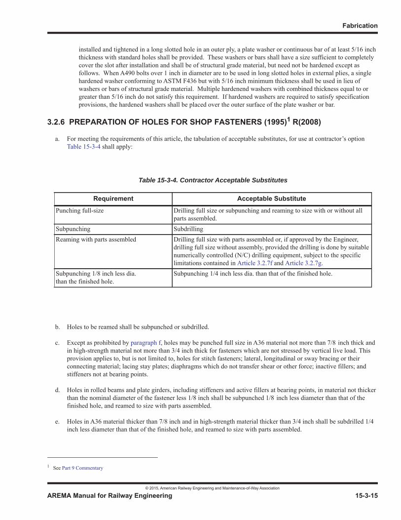
Fabrication
© 2015, American Railway Engineering and Maintenance-of-Way Association
AREMA Manual for Railway Engineering 15-3-15
1
3
4
installed and tightened in a long slotted hole in an outer ply, a plate washer or continuous bar of at least 5/16 inch thickness with standard holes shall be provided. These washers or bars shall have a size sufficient to completely cover the slot after installation and shall be of structural grade material, but need not be hardened except as follows. When A490 bolts over 1 inch in diameter are to be used in long slotted holes in external plies, a single hardened washer conforming to ASTM F436 but with 5/16 inch minimum thickness shall be used in lieu of washers or bars of structural grade material. Multiple hardenend washers with combined thickness equal to or greater than 5/16 inch do not satisfy this requirement. If hardened washers are required to satisfy specification provisions, the hardened washers shall be placed over the outer surface of the plate washer or bar.
3.2.6 PREPARATION OF HOLES FOR SHOP FASTENERS (1995)1 R(2008)
a. For meeting the requirements of this article, the tabulation of acceptable substitutes, for use at contractor’s option Table 15-3-4 shall apply:
b. Holes to be reamed shall be subpunched or subdrilled.
c. Except as prohibited by paragraph f, holes may be punched full size in A36 material not more than 7/8 inch thick and in high-strength material not more than 3/4 inch thick for fasteners which are not stressed by vertical live load. This provision applies to, but is not limited to, holes for stitch fasteners; lateral, longitudinal or sway bracing or their connecting material; lacing stay plates; diaphragms which do not transfer shear or other force; inactive fillers; and stiffeners not at bearing points.
d. Holes in rolled beams and plate girders, including stiffeners and active fillers at bearing points, in material not thicker than the nominal diameter of the fastener less 1/8 inch shall be subpunched 1/8 inch less diameter than that of the finished hole, and reamed to size with parts assembled.
e. Holes in A36 material thicker than 7/8 inch and in high-strength material thicker than 3/4 inch shall be subdrilled 1/4 inch less diameter than that of the finished hole, and reamed to size with parts assembled.
1 See Part 9 Commentary
Table 15-3-4. Contractor Acceptable Substitutes
Requirement Acceptable Substitute
Punching full-size Drilling full size or subpunching and reaming to size with or without all parts assembled.
Subpunching SubdrillingReaming with parts assembled Drilling full size with parts assembled or, if approved by the Engineer,
drilling full size without assembly, provided the drilling is done by suitable numerically controlled (N/C) drilling equipment, subject to the specific limitations contained in Article 3.2.7f and Article 3.2.7g.
Subpunching 1/8 inch less dia.than the finished hole.
Subpunching 1/4 inch less dia. than that of the finished hole.
Steel Structures
© 2015, American Railway Engineering and Maintenance-of-Way Association
15-3-16 AREMA Manual for Railway Engineering
f. Where matching holes in two or more plies of material are required to be reamed with parts assembled and the assembly consists of more than five plies with more than three plies of main material, the matching holes in other plies shall also be reamed with parts assembled, with holes in these other plies subpunched 1/8 inch less diameter than that of the finished hole.
g. Other holes for shop fasteners shall be subpunched 1/4 inch less in diameter than that of the finished hole, and reamed to size with parts assembled.
h. If approved by the Engineer, the contractor shall have the option to drill full size through individual pieces or any combination of pieces held tightly together, the holes designated to be subpunched or subdrilled and reamed in paragraph d, paragraph e, paragraph f and paragraph g, provided the drilling is done by suitable numerically controlled (N/C) drilling equipment, subject to the specific limitations contained in Article 3.2.7f and Article 3.2.7g.
3.2.7 PREPARATION OF HOLES FOR FIELD FASTENERS (2007)1 R(2008)
a. Field splices in plate girders and in truss chords shall be reamed or drilled full size with the members assembled. Truss chord assemblies shall consist of at least three abutting sections, and milled ends of compression chords shall have full bearing.
b. Holes for field fasteners where assembly is not required shall be either:
(1) subpunched or subdrilled 1/4 inch less in diameter than that of the finished holes and reamed to size through steel templates with hardened steel bushings, or
(2) drilled full size through steel templates with hardened steel bushings.
c. Holes in A 36 material thicker than 7/8 inch and in high-strength material thicker than 3/4 inch shall be either:
(1) subdrilled 1/4 inch less in diameter than that of the finished holes and reamed to size with parts assembled, or
(2) drilled full size with parts assembled.
d. Holes for field fasteners in lateral, longitudinal or sway bracing shall conform to the requirements for shop fastener holes in such members.
e. If approved by the Engineer, the fabricator shall have the option to drill full size into unassembled pieces, the holes designated in paragraph a, paragraph b, or paragraph c to be assembled reamed or drilled full size, provided the drilling is done by suitable numerically controlled (N/C) drilling equipment, subject to the specific limitations contained in paragraph f and paragraph g.
f. Where N/C drilling equipment is used, the fabricator shall, if required by the Engineer, demonstrate by means of check shop assemblies that the drilling equipment will consistently produce holes and connections meeting all of the requirements of Article 3.2.5 and Article 3.2.12.
g. Where check shop assemblies are designated, paragraph a shall be modified to require a check shop assembly for either one line of plate girders or for three abutting chord sections, one each for the top and bottom chords, of one truss including representative web members which connect to these chord assemblies.
Composition of check shop assemblies shall be based on the proposed order of erection, joints in bearing, special complex points and similar considerations. The fabricator shall submit his designation of members to be shop assembled to the Engineer for approval. If the shop assembly fails to produce holes and connections meeting the
1 See Part 9 Commentary
Fabrication
© 2015, American Railway Engineering and Maintenance-of-Way Association
AREMA Manual for Railway Engineering 15-3-17
1
3
4
requirements of Article 3.2.5 and Article 3.2.12, the Engineer may require further shop assemblies or may rescind his approval for the use of N/C drilling equipment.
h. When a span, intended to carry an active track, is to be erected during a work window between trains, all connections necessary for the erected span’s ability to carry traffic shall be checked by shop assembly unless exempted by the Engineer.
3.2.8 TEMPLATES FOR REAMING AND DRILLING (1983) R(2008)
Each steel template shall have hardened steel bushings accurately positioned with respect to connection center-lines inscribed on the template.
3.2.9 REAMING AND DRILLING THROUGH TEMPLATES (1995) R(2008)
a. Reaming or drilling full size of field connections through templates shall be done only after the templates have been positioned with the utmost care, and firmly clamped or bolted. Templates used for the reaming of matching members, or of the opposite faces of one member, shall be exact duplicates. Templates for connections which duplicate shall be so accurately positioned that like members are duplicates and require no match-marking.
b. Where templates are used to ream or drill field connections of truss web members, at least one end of each such member shall be milled or scribed normal to the long axis of the member, and the templates shall be accurately set at both ends with respect to this milled or scribed end. Templates for reaming or drilling truss gusset plates shall be accurately positioned to the geometric dimensions shown on the shop plans.
c. Templates for field connector holes for joining floor sections to girders or trusses shall be positioned so as to space the field connectors correctly from the floor expansion joints.
3.2.10 REAMING AND DRILLING AFTER ASSEMBLY (1995) R(2008)
Reaming, or drilling full size, of assembled parts shall be done only after the parts are firmly clamped together with the surfaces in close contact. If necessary, parts shall be separated before riveting or bolting for removal of shavings.
3.2.11 MATCH MARKING (1995) R(2015)
Parts assembled in the shop for reaming or drilling holes for field connectors shall be match marked before disassembly. Diagrams showing match marks shall be furnished to the Engineer.
3.2.12 ALIGNMENT OF FINISHED HOLES (1995) R(2015)
a. The offset in any hole reamed 1/4 inch in any ply of material measured from an outer ply after the hole has been finished for riveting or bolting, shall not exceed 1/16 inch. Not more than 10% of the holes shall be offset as much as 1/16 inch and not more than 20% shall be offset as much as 1/32 inch.
b. The offset in any hole reamed 1/8 inch or punched full size, in any ply of material, measured from an outer ply after the hole has been finished for riveting or bolting, shall not exceed 1/8 inch. Not more than 10% of the holes shall be offset as much as 1/8 inch, and not more than 20% shall be offset as much as 1/16 inch.
c. Where approved by the Engineer, holes may be overreamed to meet these requirements, and larger rivets or bolts installed.
Steel Structures
© 2015, American Railway Engineering and Maintenance-of-Way Association
15-3-18 AREMA Manual for Railway Engineering
3.2.13 FITTING FOR SHOP RIVETING OR BOLTING (1995) R(2015)
The parts of riveted or bolted members shall be adequately pinned and firmly drawn together in close contact with bolts before riveting or final bolting is begun. Tack welding shall not be used. The drifting done during assembly shall be only such as to bring the parts into position and shall not enlarge the holes or distort the metal.
3.2.14 TESTING AND DOCUMENTATION OF ASTM A325 AND A490 BOLTS (2012)1R(2015)
3.2.14.1 Bolt Testing
a. Bolts:
(1) Proof load tests in accordance with Method 1 of ASTM F606 are required. Minimum frequency of tests shall be as specified in ASTM A325 and A490 per the production lot method.
(2) Wedge tests on full size bolts (ASTM F606 paragraph 3.5) are required. If bolts are to be galvanized, tests shall be performed after galvanizing. Minimum frequency of tests shall be as specified in ASTM A325 and A490 per the production lot method.
(3) If galvanized bolts are supplied, the thickness of the zinc coating shall be measured. Measurements shall be taken on the wrench flats or top of bolt head.
b. Nuts:
(1) Proof load tests (ASTM F606 paragraph 4.2) are required. Minimum frequency of tests shall be as specified in ASTM A563 paragraph 9.3. If nuts are to be galvanized, tests shall be performed after galvanizing, overtapping and lubricating.
(2) If galvanized nuts are supplied, the thickness of the zinc coating shall be measured. Measurements shall be taken on the wrench flats.
c. Washers:
(1) If galvanized washers are supplied, hardness testing shall be performed after galvanizing. (Coating shall be removed prior to taking hardness measurements.)
(2) If galvanized washers are supplied, the thickness of the zinc coating shall be measured.
d. Assemblies:
(1) Rotational capacity tests are required and shall be performed on all ASTM A325 and A490 bolt, nut and washer assemblies by the manufacturer or distributor prior to shipping. Washers are required as part of the test procedure. Galvanized A325 assemblies shall be tested after galvanizing.
(2) Each combination of bolt production lot, nut lot and washer lot shall be tested as an assembly. Where washers are not required by the installation procedures, they need not be included in the lot identification.
(3) A rotational-capacity lot number shall be assigned to each combination of lots tested.
(4) The minimum frequency of testing shall be two assemblies per rotational capacity lot.
1 See Part 9 Commentary
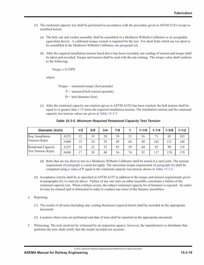
Fabrication
© 2015, American Railway Engineering and Maintenance-of-Way Association
AREMA Manual for Railway Engineering 15-3-19
1
3
4
(5) The rotational capacity test shall be performed in accordance with the procedure given in ASTM A325 except as modified herein:
(a) The bolt, nut and washer assembly shall be assembled in a Skidmore-Wilhelm Calibrator or an acceptable equivalent device. A calibrated torque wrench is required for the test. For short bolts which are too short to be assembled in the Skidmore-Wilhelm Calibrator, see paragraph (d).
(b) After the required installation tension listed above has been exceeded, one reading of tension and torque shall be taken and recorded. Torque and tension shall be read with the nut rotating. The torque value shall conform to the following:
Torque 0.25PD
where:
(c) After the rotational capacity nut rotation (given in ASTM A325) has been reached, the bolt tension shall be equal to or greater than 1.15 times the required installation tension. The installation tension and the rotational capacity test tension values are given in Table 15-3-5.
(d) Bolts that are too short to test in a Skidmore-Wilhelm Calibrator shall be tested in a steel joint. The tension requirement of paragraph (c) need not apply. The maximum torque requirement of paragraph (b) shall be computed using a value of P equal to the rotational capacity test tension shown in Table 15-3-5.
(6) Acceptance criteria shall be as specified in ASTM A325 in addition to the torque and tension requirements given in paragraphs (b), (c) and (d) above. Failure of any one item on either assembly constitutes a failure of the rotational capacity test. When a failure occurs, the subject rotational capacity lot of fasteners is rejected. An entire lot may be cleaned and re-lubricated in order to conduct one retest of the fastener assemblies.
e. Reporting:
(1) The results of all tests (including zinc coating thickness) required herein shall be recorded on the appropriate document.
(2) Location where tests are performed and date of tests shall be reported on the appropriate document.
f. Witnessing. The tests need not be witnessed by an inspection agency; however, the manufacturer or distributor that performs the tests shall certify that the results recorded are accurate.
Torque = measured torque (foot-pounds)P = measured bolt tension (pounds)D = bolt diameter (feet)
Table 15-3-5. Minimum Required Rotational Capacity Test Tension
Diameter (Inch) 1/2 5/8 3/4 7/8 1 1-1/8 1-1/4 1-3/8 1-1/2
Req. InstallationTension (Kips)
A325 12 19 28 39 51 56 71 85 103A490 15 24 35 49 64 80 102 121 148
Rotational Capacity Test Tension (Kips)
A325 14 22 32 45 59 64 82 98 118A490 17 28 40 56 74 92 117 139 170

Steel Structures
© 2015, American Railway Engineering and Maintenance-of-Way Association
15-3-20 AREMA Manual for Railway Engineering
3.2.14.2 Documentation
a. Mill Test Report(s) (MTR):
(1) MTR shall be furnished for all mill steel used in the manufacture of the bolts, nuts, or washers.
(2) MTR shall indicate the place where the material was melted and manufactured.
b. Manufacturer Certified Test Report(s) (MCTR):
(1) The manufacturer of the bolts, nuts and washers shall furnish test reports (MCTR) for the item furnished.
(2) Each MCTR shall show the relevant information required in accordance with Article 3.2.14.1e.
(3) The manufacturer performing the rotational-capacity test shall include on the MCTR:
(a) The lot number of each of the items tested.
(b) The rotational-capacity lot number as required in Article 3.2.14.1d(2)(3).
(c) The results of the tests required in Article 3.2.14.1d.
(d) The pertinent information required in Article 3.2.14.1e(2).
(e) A statement that MCTR for the items are in conformance to this recommended practice.
(f) The location where the bolt assembly components were manufactured.
c. Distributor Certified Test Report(s) (DCTR):
(1) The DCTR shall include MCTR above for the various bolt assembly components.
(2) The rotational-capacity test may be performed by a distributor (in lieu of a manufacturer) and reported on the DCTR.
(3) The DCTR shall show the results of the tests required in Article 3.2.14.1d.
(4) The DCTR shall also show the pertinent information required in Article 3.2.14.1e(2).
(5) The DCTR shall show the rotational-capacity lot number as required in Article 3.2.14.1d(2)(3).
(6) The DCTR shall certify that the MCTRs are in conformance with this recommended practice.

Fabrication
© 2015, American Railway Engineering and Maintenance-of-Way Association
AREMA Manual for Railway Engineering 15-3-21
1
3
4
SECTION 3.3 WELDED CONSTRUCTION
3.3.1 GENERAL (2014)1 R(2015)
a. These recommended practices cover requirements for welding practices and inspection to ensure that the resulting structure will be satisfactory for service. The AWS D1.5 shall be used for all requirements not specifically covered in these recommended practices.
b. Electroslag and electrogas welding processes shall not be used.
c. Welding of Fracture Critical Members shall be in accordance with the requirements of Part 1, Design, Section 1.14, Fracture Critical Members.
d. Welded flange splices shall be located with a separation of 6 inches or more from a web splice, a welded stiffener, or any other connection welded to the flange.
e. Welded splices of rolled beams shall be located in a single transverse plane with a separation of 6 inches or more from a welded stiffener, or any other connection welded to the section.
3.3.2 PREPARATION OF MATERIAL FOR WELDING (1995) R(2015)
Surfaces within 2 inches of any weld location shall be free from any paint or other material which would prevent proper welding or produce objectionable fumes while welding.
3.3.3 FLANGE-TO-WEB WELDS OF FLEXURAL MEMBERS (1995)2 R(2015)
Flange-to-Web welds of flexural members shall be made by machine welding.
3.3.4 TACK WELDS (1995)3 R(2015)
Transverse tack welds on tension flanges of flexural members are prohibited.
3.3.5 WELDER AND WELDING OPERATOR QUALIFICATIONS (1997) R(2015)
Welds shall be made only by welders, welding operators and tack welders currently qualified, in accordance with AWS D1.5, to perform the type of work required.
SECTION 3.4 SHOP PAINTING
3.4.1 SHOP PAINTING OF STRUCTURAL STEEL (2003) R(2008)
a. Steel surfaces for new structural steel fabrication, shall be prepared and painted in accordance with the “Standard Specification for Coating Systems with Inorganic Zinc-Rich Primer” (AASHTO/NSBA Steel Bridge Collaboration publication S8.1) as prepared by the AASHTO/NSBA Steel Collaboration Task Group 8, Coatings, unless another coating system is specified by the Company.
1 See Part 9 Commentary2 See Part 9 Commentary3 See Part 9 Commentary

Steel Structures
© 2015, American Railway Engineering and Maintenance-of-Way Association
15-3-22 AREMA Manual for Railway Engineering
b. For welded construction, slag shall be cleaned from all welds. Welded joints shall not be painted until after the work has been completed and accepted. The surfaces to be painted shall be cleaned of spatter, rust, loose scale, oil and dirt.
c. Shop and field contact surfaces shall not be painted unless required by the Engineer.
d. Weathering steels, ASTM A588, A709, Grade 50W, Grade HPS 50W, and Grade HPS 70W need not be shop painted provided the shop painting requirement is waived in the contract documents or is otherwise deleted by the Engineer.
3.4.2 SHOP PAINTING OF MACHINED SURFACES (1995) R(2015)
a. Machine finished surfaces of steel (except abutting joints and base plates) shall be protected against corrosion by a rust-inhibiting coating which can be removed readily prior to erection, or which has characteristics which make removal unnecessary prior to erection. This coating shall be applied as soon as the surfaces have been finished and approved by the Inspector.
b. Abutting joints and base plates shall be painted as required by Article 3.4.1a.
SECTION 3.5 INSPECTION
3.5.1 FACILITIES FOR INSPECTION (1991) R(2015)
The Contractor shall provide to the Inspector, without charge, facilities for the inspection of materials and workmanship. The Inspector shall be allowed free access to the fabricating areas.
3.5.2 INSPECTOR AUTHORITY (1991) R(2015)
The Inspector shall have authority to reject materials or workmanship that do not meet the requirements of the contract documents. In case of dispute, the Contractor may appeal to the Engineer, whose decision shall be final.
3.5.3 REJECTION (1991) R(2015)
a. The acceptance by the Inspector of material or finished members shall not prevent their rejection later if found defective.
b. Rejected material and workmanship shall promptly be replaced or made good by the Contractor.
3.5.4 INSPECTION – HIGH-STRENGTH BOLTED JOINTS (2003) R(2008)
a. The Inspector shall observe the installation and tightening of bolts to determine that the specified tightening procedure is properly used, and shall determine that all bolts have been tightened.
b. When there is disagreement concerning the results of tension in the turn-of-nut method of installation, the arbitration procedure described in the current Specification for Structural Joints using A325 and A490 Bolts approved by the Research Council on Structural Connections (RCSC) shall be used, unless a different procedure is specified in the inquiry and order for the work. Required fastener tension shall be as specified in Part 1, Design, Table 15-1-12 (not as specified in the RCSC specifications).
Fabrication
© 2015, American Railway Engineering and Maintenance-of-Way Association
AREMA Manual for Railway Engineering 15-3-23
1
3
4
3.5.5 INSPECTION – WELDED WORK (2002)1 R(2008)
a. All weld inspection shall be performed by the Inspector, or shall be witnessed by him. The Contractor shall place pieces so that the Inspector has ready access. When specified on the design plans or in special provisions covering the work, the Contractor may be required to perform specific non-destructive testing work, such as radiography, etc., but this must be witnessed by the Inspector. The Inspector must not unnecessarily delay such inspection by refusing to be present when this work must be done.
b. All groove welds carrying live-load stress in flanges of flexural members and in tension members shall be inspected by radiographic, ultrasonic or another nondestructive testing method which will satisfactorily present evidence to the Engineer that the welds meet the quality requirements of the AWS D1.5. At least 10% of all other groove welds, except flange-to-web full penetration welds, shall be similarly inspected. At least 10% of the flange-to-web complete joint penetration groove welds shall be inspected by the ultrasonic method or they may be inspected by the magnetic particle method if so authorized by the Engineer. If rejectable discontinuities are found, the provisions of AWS D1.5 for additional testing shall apply.
c. At least 10% of flange-to-web fillet welds shall be inspected by the magnetic particle method unless such inspection is waived by a statement in the design plans or special provisions. If rejectable discontinuities are found, the provisions of AWS D1.5 for additional testing shall apply.
d. Inspection of welded work for Fracture Critical Members shall be in accordance with Part 1, Design, Section 1.14, Fracture Critical Members.
e. Time delay prior to NDT of weld repairs to groove welds of ASTM A588 or A709, Grade 50W, or A709, Grade HPS 50W, or A709, Grade HPS 70W material over 2 inches in thickness, subject to tensile stress, shall be 16 hours minimum.
SECTION 3.6 SHIPMENT AND PAY WEIGHT
3.6.1 MARKING, PACKAGING AND LOADING (1995) R(2015)
a. Erection marks shall be painted on all members. Members weighing more than 10 tons shall have their weight marked thereon. Marks on weathering steel shall be placed in suitable inconspicuous places.
b. The responsibilities of the shipper shall include proper loading, positioning, supporting and stabilizing of structural members in accordance with the carrier’s instructions and in case the material is damaged proper correction of the damage.
The fabricator shall make certain that structural members are loaded for shipment in a manner that will ensure that they will not be damaged in shipment. The method of loading must not adversely affect the potential life of the permanent structure. Welding of tie-down attachments to a member is prohibited.
The Engineer may request that loading diagrams be furnished to him for unusual or special members.
The Engineer may also request the fabricator to notify the Engineer when any member is ready for shipment so that the method of loading can be observed.
c. Rivets and bolts, except ASTM A325 and A490 high-strength bolts shall be packaged separately according to length and diameter. Loose nuts and washers shall be packaged separately according to size.
1 See Part 9 Commentary
Steel Structures
© 2015, American Railway Engineering and Maintenance-of-Way Association
15-3-24 AREMA Manual for Railway Engineering
d. Pins and other small parts and packages of rivets, bolts, except ASTM A325 and A490 high-strength bolts, nuts and washers shall be shipped in boxes, crates, kegs, or barrels, none of which shall exceed 300 lb gross weight. A list and description of material contained therein shall be firmly secured to or marked on the outside of each container.
e. ASTM A325 and A490 high-strength bolts, nuts, and washers (where required) from each rotational-capacity lot shall be shipped in the same container. If there is only one production lot number for each size of nut and washer, the nuts and washers may be shipped in separate containers. Each container (not the lid) shall be permanently marked with the rotational-capacity lot number such that identification will be possible at any stage prior to installation.
The appropriate Mill Test Report(s) (MTR), Manufacturer Certified Test Report(s) (MCTR) and Distributor Certified Test Report(s) (DCTR) for high-strength bolts as required in Article 3.2.14.2 shall be supplied to the Engineer.
f. Long girders shall be so loaded that they can be delivered to the site in position for erection without turning. Instructions for such delivery shall be furnished to the carrier.
g. Special precautions may be needed where girders are supported at points other than permanent support points, and where girder intermediate stiffeners are not in contact with flanges.
3.6.2 ADVANCE MATERIAL (1995) R(2015)
Anchor bolts and washers and other anchorage or grillage materials to be built into the masonry shall be shipped in time therefore.
3.6.3 PAY WEIGHT (2003)1 R(2015)
Payment in unit price contracts shall be based on the weight determined in accordance with the Code of Standard Practice of the American Institute of Steel Construction.
1 See Part 9 Commentary

© 2015, American Railway Engineering and Maintenance-of-Way Association 15-4-1
1
3
15Part 4
Erection1
— 2015 —
FOREWORD
The purpose of this part is to formulate general rules as a guide for the erection of railway bridges. Part 1, Design is applicable to erection of steel railway bridges except as modified by Part 4, Erection.
TABLE OF CONTENTS
Section/Article Description Page4.1 General (1992) R(2015) . . . . . . . . . . . . . . . . . . . . . . . . . . . . . . . . . . . . . . . . . . . . . . . . . . . . . . . . . . . . . . . . . . 15-4-2
4.2 Definitions of Terms (2015) . . . . . . . . . . . . . . . . . . . . . . . . . . . . . . . . . . . . . . . . . . . . . . . . . . . . . . . . . . . . . . . 15-4-2
4.3 Work to be Done (2002) R(2015) . . . . . . . . . . . . . . . . . . . . . . . . . . . . . . . . . . . . . . . . . . . . . . . . . . . . . . . . . . . 15-4-3
4.4 Drawings or Special Provisions to Govern (1992) R(2015). . . . . . . . . . . . . . . . . . . . . . . . . . . . . . . . . . . . . . 15-4-3
4.5 Plant (1992) R(2015). . . . . . . . . . . . . . . . . . . . . . . . . . . . . . . . . . . . . . . . . . . . . . . . . . . . . . . . . . . . . . . . . . . . . 15-4-3
4.6 Plans. . . . . . . . . . . . . . . . . . . . . . . . . . . . . . . . . . . . . . . . . . . . . . . . . . . . . . . . . . . . . . . . . . . . . . . . . . . . . . . . . . 15-4-34.6.1 Steel Structure Supplied by Company (2002) R(2008) . . . . . . . . . . . . . . . . . . . . . . . . . . . . . . . . . . . . 15-4-34.6.2 Steel Structure Fabricated by Contractor (2002) R(2008) . . . . . . . . . . . . . . . . . . . . . . . . . . . . . . . . . . 15-4-3
4.7 Delivery of Materials (1992) R(2015) . . . . . . . . . . . . . . . . . . . . . . . . . . . . . . . . . . . . . . . . . . . . . . . . . . . . . . . 15-4-3
4.8 Handling and Storing Materials (1992) R(2015) . . . . . . . . . . . . . . . . . . . . . . . . . . . . . . . . . . . . . . . . . . . . . . 15-4-4
4.9 Establishment of Lines and Elevations. . . . . . . . . . . . . . . . . . . . . . . . . . . . . . . . . . . . . . . . . . . . . . . . . . . . . . 15-4-44.9.1 Substructure Constructed by Company (2003) R(2015) . . . . . . . . . . . . . . . . . . . . . . . . . . . . . . . . . . . 15-4-44.9.2 Substructure Constructed by Contractor (2003) R(2015) . . . . . . . . . . . . . . . . . . . . . . . . . . . . . . . . . . 15-4-4
4.10 Bearings and Anchorage (2002) R(2015) . . . . . . . . . . . . . . . . . . . . . . . . . . . . . . . . . . . . . . . . . . . . . . . . . . . . 15-4-4
4.11 Erection Procedure (1992) R(2008). . . . . . . . . . . . . . . . . . . . . . . . . . . . . . . . . . . . . . . . . . . . . . . . . . . . . . . . . 15-4-4
4.12 Reinforcement of Members (1992) R(2008) . . . . . . . . . . . . . . . . . . . . . . . . . . . . . . . . . . . . . . . . . . . . . . . . . . 15-4-5
1 References, Vol. 13, 1912, pp. 83, 935; Vol. 24, 1923, pp. 146, 1143; Vol. 38 1937, p. 630; Vol. 49, 1948, pp. 206, 669; Vol. 57, 1956, pp. 555, 998; Vol. 62, 1961, pp. 550, 877; Vol. 63, 1962, pp. 386, 699; Vol. 68, 1967, p. 351; Vol. 70, 1969, p. 241; Vol. 76, 1975, p. 241; Vol. 80, 1979, p. 188; Vol. 92, 1991, p. 78; Vol. 93, 1992, p. 124; Vol. 94, p. 1. Reapproved with revisions 1993.
Steel Structures
© 2015, American Railway Engineering and Maintenance-of-Way Association
15-4-2 AREMA Manual for Railway Engineering
TABLE OF CONTENTS (CONT)
Section/Article Description Page
4.13 Falsework (1991) R(2008). . . . . . . . . . . . . . . . . . . . . . . . . . . . . . . . . . . . . . . . . . . . . . . . . . . . . . . . . . . . . . . . 15-4-5
4.14 Allowable Stresses During Erection (1991) R(2015) . . . . . . . . . . . . . . . . . . . . . . . . . . . . . . . . . . . . . . . . . . 15-4-5
4.15 Drift or Traffic Pins (1991) R(2008) . . . . . . . . . . . . . . . . . . . . . . . . . . . . . . . . . . . . . . . . . . . . . . . . . . . . . . . 15-4-5
4.16 Field Assembly of Members (1991) R(2008). . . . . . . . . . . . . . . . . . . . . . . . . . . . . . . . . . . . . . . . . . . . . . . . . 15-4-6
4.17 Fitting-up of Field Connections (1991) R(2008). . . . . . . . . . . . . . . . . . . . . . . . . . . . . . . . . . . . . . . . . . . . . . 15-4-6
4.18 Riveted Field Connections (1991) R(2008) . . . . . . . . . . . . . . . . . . . . . . . . . . . . . . . . . . . . . . . . . . . . . . . . . . 15-4-6
4.19 High-Strength Bolted Field Connections (1991) R(2015) . . . . . . . . . . . . . . . . . . . . . . . . . . . . . . . . . . . . . . 15-4-7
4.20 Field Welding (1991) R(2015) . . . . . . . . . . . . . . . . . . . . . . . . . . . . . . . . . . . . . . . . . . . . . . . . . . . . . . . . . . . . 15-4-7
4.21 Field Connections Using Pins (1991) R(2015) . . . . . . . . . . . . . . . . . . . . . . . . . . . . . . . . . . . . . . . . . . . . . . . 15-4-7
4.22 Field Inspection (1991) R(2015). . . . . . . . . . . . . . . . . . . . . . . . . . . . . . . . . . . . . . . . . . . . . . . . . . . . . . . . . . . 15-4-7
4.23 Misfits (1991) R(2015). . . . . . . . . . . . . . . . . . . . . . . . . . . . . . . . . . . . . . . . . . . . . . . . . . . . . . . . . . . . . . . . . . . 15-4-7
4.24 Field Cleaning and Painting (2002) R(2008) . . . . . . . . . . . . . . . . . . . . . . . . . . . . . . . . . . . . . . . . . . . . . . . . 15-4-8
4.25 Deck (1991) R(2015) . . . . . . . . . . . . . . . . . . . . . . . . . . . . . . . . . . . . . . . . . . . . . . . . . . . . . . . . . . . . . . . . . . . . 15-4-8
4.26 Removal of Old Structure and Falsework, and Cleanup (1991) R(2015) . . . . . . . . . . . . . . . . . . . . . . . . . 15-4-8
4.27 Interference with Traffic (1983) R(2015) . . . . . . . . . . . . . . . . . . . . . . . . . . . . . . . . . . . . . . . . . . . . . . . . . . . 15-4-9
4.28 Company Equipment (1983) R(2015) . . . . . . . . . . . . . . . . . . . . . . . . . . . . . . . . . . . . . . . . . . . . . . . . . . . . . . 15-4-9
4.29 Work Train Service (1983) R(2015) . . . . . . . . . . . . . . . . . . . . . . . . . . . . . . . . . . . . . . . . . . . . . . . . . . . . . . . 15-4-9
4.30 Risk (1983) R(2015). . . . . . . . . . . . . . . . . . . . . . . . . . . . . . . . . . . . . . . . . . . . . . . . . . . . . . . . . . . . . . . . . . . . . 15-4-9
4.31 Laws and Permits (1983) R(2015) . . . . . . . . . . . . . . . . . . . . . . . . . . . . . . . . . . . . . . . . . . . . . . . . . . . . . . . . . 15-4-9
4.32 Patents (1983) R(2015) . . . . . . . . . . . . . . . . . . . . . . . . . . . . . . . . . . . . . . . . . . . . . . . . . . . . . . . . . . . . . . . . . . 15-4-10
SECTION 4.1 GENERAL (1992) R(2015)
These recommended practices establish general rules for the erection of railway bridges. For work of a special nature, or work to be done under unusual conditions, these recommended practices may be modified, or supplemented, to adapt them to special requirements. When applicable these general rules apply to contracted work or work to be done by Company forces.
SECTION 4.2 DEFINITIONS OF TERMS (2015)
See Article 1.1.1.

Erection
© 2015, American Railway Engineering and Maintenance-of-Way Association
AREMA Manual for Railway Engineering 15-4-3
1
3
4
SECTION 4.3 WORK TO BE DONE (2002) R(2015)
The Contractor shall erect the metalwork including erecting and removal of special erecting devices and falsework as required and shall make all connections and adjustments, and do all the work required to complete the bridge superstructure, in accordance with the plans, special contract provisions, and these recommended practices, and as required by the terms of the contract.
SECTION 4.4 DRAWINGS OR SPECIAL PROVISIONS TO GOVERN (1992) R(2015)
Where the drawings, special provisions and/or these recommended practices differ, the drawings, special provisions and these recommended practices shall govern in that order.
SECTION 4.5 PLANT (1992) R(2015)
The Contractor shall provide all tools, equipment, temporary connectors, special erecting devices, and erecting falsework as required for the expeditious handling of the work and for completion within the time specified.
SECTION 4.6 PLANS
4.6.1 STEEL STRUCTURE SUPPLIED BY COMPANY (2002) R(2008)
a. The Company will be responsible for furnishing, if available, the complete detail plans for the steel structure or structures to be erected, including shop drawings, shop details, camber diagrams, erection diagrams, match marking diagrams, list of field fasteners, and shipping statements showing a full list of parts and weights.
b. The Contractor shall prepare erection procedures and submit them for review and acceptance by the Company.
4.6.2 STEEL STRUCTURE FABRICATED BY CONTRACTOR (2002) R(2008)
a. The Company will be responsible for furnishing the design drawings and special provisions for the steel structure or structures to be fabricated and erected.
b. The Contractor shall prepare shop drawings, shop details, camber diagrams, erection diagrams, match marking diagrams, list of field fasteners, erection procedures, and shipping statements showing a full list of parts and weights; and shall submit them for review and acceptance by the Company.
SECTION 4.7 DELIVERY OF MATERIALS (1992) R(2015)
Where the contract indicates that materials are to be furnished by the Company, the Contractor shall receive all such materialsat the place and under the terms specified in the contract documents.
Steel Structures
© 2015, American Railway Engineering and Maintenance-of-Way Association
15-4-4 AREMA Manual for Railway Engineering
SECTION 4.8 HANDLING AND STORING MATERIALS (1992) R(2015)
a. Where the contract requires unloading of the materials, the Contractor shall unload promptly on delivery. Demurrage charges, when unloading is delayed for reasons within the control of the Contractor, shall be his responsibility.
b. Stored material shall be piled securely at least 12 feet clear from the center line of the track. Material shall be placed onblocking, above the ground. It shall be kept clean and properly drained. Long members, such as columns, chords and girders, shall be supported on blocking placed close enough together to prevent injury from deflection. The Contractor shall check all material turned over to him against shipping lists and report promptly in writing any shortage or damage discovered. The Contractor will be held responsible for the loss of any material while in his care, or for any damage resulting from his work.
SECTION 4.9 ESTABLISHMENT OF LINES AND ELEVATIONS
4.9.1 SUBSTRUCTURE CONSTRUCTED BY COMPANY (2003) R(2015)
The Company will be responsible for the construction of the substructure to correct lines and elevations, and for the establishment of the lines and elevations required by the Contractor for setting the steelwork.
4.9.2 SUBSTRUCTURE CONSTRUCTED BY CONTRACTOR (2003) R(2015)
The Contractor shall be responsible for the construction of the substructure to correct lines and elevations, and for the establishment of the lines and elevations required for setting the steelwork.
SECTION 4.10 BEARINGS AND ANCHORAGE (2002) R(2015)
Refer to Part 5.
SECTION 4.11 ERECTION PROCEDURE (1992) R(2008)
a. To assure the Company that erection will proceed in an orderly sequence and that it will be completed within the contract time, the Contractor shall advise the Engineer fully as to the procedure which will be followed and the amount and kind of equipment which he proposes to use. When required by the nature of the structure and so stipulated in the special provisions of the contract, erection procedure plans shall be prepared by the Contractor.
b. The Engineer will review the information and plans submitted in accordance with paragraph a, and his approval shall be obtained before field erection may be started. This approval shall not be considered as relieving the Contractor of his responsibility for the safety of the procedure and equipment, or from carrying out the work in compliance with the contract requirements.

Erection
© 2015, American Railway Engineering and Maintenance-of-Way Association
AREMA Manual for Railway Engineering 15-4-5
1
3
4
SECTION 4.12 REINFORCEMENT OF MEMBERS (1992) R(2008)
Where the approved erection procedure requires the reinforcement or modification of any members of the permanent structure, the Contractor shall make such arrangements as are necessary with the fabricator for having this done. Such reinforcement or modification shall be at the Contractor’s expense, and shall be subject to the approval of the Engineer. Such approval shall notrelieve the Contractor from responsibility for avoiding damage or detrimental overstress in the permanent member of the structure at all times during erection.
SECTION 4.13 FALSEWORK (1991) R(2008)
Where the approved erection procedure involves the use of falsework, the Contractor shall prepare and submit to the Engineer for review, plans for the falsework. The falsework shall be properly designed and substantially constructed for the loads to which it will be subjected. Review by the Engineer of the Contractor’s plans shall not be considered as relieving the Contractorof full responsibility.
SECTION 4.14 ALLOWABLE STRESSES DURING ERECTION (1991) R(2015)
a. During erection, members and connections subject to erection loads shall not be stressed to more than 1.25 times the basic allowable stress. When the erection loads are combined with wind loads, members and connections shall not be stressed to more than 1.33 times the basic allowable stress.
b. The allowable shear stress for drift or traffic pins in a fitted-up connection shall be 20,000 psi.
c. Fully torqued high-strength bolts and drift or traffic pins in the same connection plane may be considered as sharing the stress.
SECTION 4.15 DRIFT OR TRAFFIC PINS (1991) R(2008)
a. Drift or traffic pins (cylindrical body pins with tapered ends to facilitate driving) shall be used to line up the open holesin a connection. They shall have the same nominal diameter as that of the open hole into which they are driven.
b. Drift or traffic pins shall be of hardened steel with a minimum yield strength of 50,000 psi.
c. Drift or traffic pins shall not be driven to deform the material but only to line up the holes. High-strength bolts or temporary fit-up bolts shall be used in combination with the pins to hold the plies of material together during the fit-up process.
Steel Structures
© 2015, American Railway Engineering and Maintenance-of-Way Association
15-4-6 AREMA Manual for Railway Engineering
SECTION 4.16 FIELD ASSEMBLY OF MEMBERS (1991) R(2008)
a. Members shall be accurately assembled as shown on the plans and carefully handled so that no parts will be bent, broken or otherwise damaged. Hammering which will injure or distort the members will not be permitted. Bearing surfaces and surfaces to be in permanent contact shall be cleaned just before the members are assembled as required by Section 4.24a.
b. Unless erected by the cantilever method, truss spans shall be erected on blocking or falsework so placed as to accommodate proper truss camber.
c. Beams and girders which are field spliced shall be erected on blocking, falsework, or held in the falls until sufficient holes in the splices can be made fair and have been fitted-up as required by Section 4.17.
SECTION 4.17 FITTING-UP OF FIELD CONNECTIONS (1991) R(2008)
a. The Contractor shall furnish the Company information showing the erection and/or erection plus erection wind forces in all members, and shall show his proposed provisions for withstanding these forces and procedure for fitting-up the connections.
b. All connections shall be accurately aligned by driving sufficient drift or traffic pins in a pattern to fair-up the holes. Light drifting will be permitted to effect this fairing-up of the holes, but heavy drifting which would deform the material shall not be permitted. Unfair holes may be reamed or drilled oversize and corresponding high-strength bolts or rivets used in such holes, subject to review and approval by the Engineer. Sufficient fitting-up bolts shall be used with pins as necessary to bring the parts into contact and to stabilize the joint during alignment.
c. Following fairing-up of the holes, fitting-up of the connection shall be completed with fitting-up bolts and pins in a pattern suitable to hold the joint material together and to withstand calculated erection stresses until final bolting or riveting is accomplished.
d. Where plain A325 high-strength bolts are used as the field connectors the same bolts may be used both for fitting-up and for final bolting. Where galvanized A325 high-strength bolts or A490 high-strength bolts are used as the field connectors, the same bolts, if tightened to no more than snug-tight fitting-up, may be used for final bolting. Galvanized A325 high-strength bolts and A490 bolts shall not be re-used after having been once fully tightened.
e. Snug-tight is the tightness attained by a few impacts of an impact wrench or the full effort of a man using an ordinary spud wrench.
SECTION 4.18 RIVETED FIELD CONNECTIONS (1991) R(2008)
a. Where rivets are used in field connections, they shall be driven with pneumatic riveting hammers, and when practical, shall be bucked with pneumatic buckers.
b. The requirements for the rivets, and for the general procedure of heating and driving, shall be as specified in Part 3, Fabrication, Article 3.2.1.
Erection
© 2015, American Railway Engineering and Maintenance-of-Way Association
AREMA Manual for Railway Engineering 15-4-7
1
3
4
SECTION 4.19 HIGH-STRENGTH BOLTED FIELD CONNECTIONS (1991) R(2015)
a. Where high-strength bolts are used in field connections, they shall meet the requirements of Part 3, Fabrication,Article 3.2.2.
b. The installation procedure for permanent high-strength bolts and for fully tightened high strength fitting-up bolts shall be as specified in Part 3, Fabrication, Article 3.2.3.
SECTION 4.20 FIELD WELDING (1991) R(2015)
Field welding, where permitted by the provisions of Part 1, Design, Article 1.5.10, shall be done in accordance with the provisions of Section 3.3.
SECTION 4.21 FIELD CONNECTIONS USING PINS (1991) R(2015)
Pins may be driven or jacked into place. Pin nuts shall be screwed tight, and the threads burred, unless another means of retaining the pin nut is specified.
SECTION 4.22 FIELD INSPECTION (1991) R(2015)
a. The work shall be subject at all times to inspection by the Engineer or the Inspector.
b. The requirements for inspection and procedures to be followed for each type of work shall be as specified in Section 3.5.
SECTION 4.23 MISFITS (1991) R(2015)
a. The correction of non-repetitive minor misfits shall be done by the Contractor without additional compensation.
b. Any error in shop work which prevents the proper assembling and fitting up of parts by the moderate use of drift or traffic pins or a moderate amount of reaming and slight chipping or cutting, shall immediately be reported to the Inspector, and his approval of the method of correction obtained. The correction shall be made in the presence of the Inspector, who will check the time and material. Where material requiring correction is furnished by the Company, the Contractor shall render to the Company within 30 days an itemized bill for such work of correction for the approval of the Engineer.
Steel Structures
© 2015, American Railway Engineering and Maintenance-of-Way Association
15-4-8 AREMA Manual for Railway Engineering
SECTION 4.24 FIELD CLEANING AND PAINTING (2002) R(2008)
a. Unpainted field contact surfaces shall be thoroughly wire brushed to remove loose rust and loose mill scale, and any grease or shop paint on such surfaces shall be removed with proper solvents.
b. Where the rust-inhibiting coating on machined surfaces required by Part 3, Fabrication, Article 3.4.2a is of a type which must be removed prior to erection, such coating shall be removed immediately prior to field assembly of mating surfaces so that rust will not form.
c. The intermediate and finish coats of field paint shall be in accordance with the system selected and specified by the Engineer from Table 1 – General Painting Guide for Steel Structures of the Steel Structures Painting Council Manual, Vol. 2.
d. Steel work inaccessible after placing of deck shall be field painted before the deck is placed.
e. Weathering steels, ASTM A588, and A709 Grade 50W, Grade HPS 50W, and Grade HPS 70W, need not be field painted provided the field painting requirement is waived in the contract documents or is otherwise deleted by the Engineer.
SECTION 4.25 DECK (1991) R(2015)
Where required by the special provisions and the terms of the contract, the ties, guard timbers, guard rails, fire decking, concrete decking, waterproofing, ballast, deck planking, track rails, and tie plates, and other specified deck appurtenances shallbe placed and, when applicable, fastened by the Contractor in accordance with the plans, specifications, and special provisionsfurnished by the Company. Unless otherwise specified, all such material will be delivered by the Company to the Contractor. If treated timber is used, the Company will deliver it properly framed to the Contractor. Untreated ties shall be framed by the Contractor to give a full and even bearing on girders or stringers and under the rails. Where necessary to do any framing or cutting of treated timber, the resulting surfaces shall be treated with wood preservatives as directed by the Engineer.
SECTION 4.26 REMOVAL OF OLD STRUCTURE AND FALSEWORK, AND CLEANUP (1991) R(2015)
a. Where required by special provisions and terms of the contract, the Contractor shall dismantle the old structure and either load the material on cars for shipment or pile it neatly at a site immediately adjacent to the tracks with clearance specified in Section 4.8b, and at an elevation convenient for future handling, as specified. Where the old structure is to be used again, it shall be dismantled without unnecessary damage and the parts match marked according to diagrams furnished by the Company.
b. Where the falsework is the property of the Company, the Contractor shall follow the same procedure as specified by paragraph a.
c. Where the falsework is the property of the Contractor, he shall dismantle it and remove it completely from the site.
d. The Contractor shall cut off piling at the surface of the ground, or at a lower elevation, or shall completely remove it as required by the special provisions and terms of the contract.
Erection
© 2015, American Railway Engineering and Maintenance-of-Way Association
AREMA Manual for Railway Engineering 15-4-9
1
3
4
e. On completion of his work, the Contractor shall remove all debris and refuse from the site, and leave the premises in good condition.
SECTION 4.27 INTERFERENCE WITH TRAFFIC (1983) R(2015)
a. The special provisions and terms of the contract will state definitely the procedures to be followed by the Contractor to minimize interference with the movement of trains where the structure is being erected under traffic.
b. The special provisions and terms of the contract will stipulate any special requirements which may apply to interference with waterborne traffic when the structure is erected over a navigable body of water.
c. The special provisions and terms of the contract will stipulate any special requirements which may apply to interference with vehicular or railroad traffic above or below the structure being erected.
SECTION 4.28 COMPANY EQUIPMENT (1983) R(2015)
When the special provisions and terms of the contract provide that the Company will furnish equipment to the Contractor, such as flat cars, water cars, bunk cars, etc., the Contractor shall repair all damage to such equipment furnished for his use and return it in as good condition as when he received it, less normal wear and tear.
SECTION 4.29 WORK TRAIN SERVICE (1983) R(2015)
Where the special provision and terms of the contract provide that work train or engine service is furnished to the Contractor without charge, the Contractor shall state in his bid the number of days such service will be required. Any excess over the timespecified in this bid shall be paid for by the Contractor at the Company’s schedule of rates.
SECTION 4.30 RISK (1983) R(2015)
The Contractor shall be responsible for loss or damage to materials, for all damage to persons or property, and for casualties ofevery description caused by his operations during the progress of the work. Injuries or losses due to events beyond the controlof the Contractor shall not be borne by him unless they occurred because he was dilatory in handling the work, with the result of extending the time beyond the limit designated in the contract.
SECTION 4.31 LAWS AND PERMITS (1983) R(2015)
a. Permits for the location and construction of the structure shall be obtained as directed by the Company.
Steel Structures
© 2015, American Railway Engineering and Maintenance-of-Way Association
15-4-10 AREMA Manual for Railway Engineering
b. The Contractor shall comply with Federal, State and local laws, regulations and ordinances, and shall obtain at his expense the necessary permits for his operations.
SECTION 4.32 PATENTS (1983) R(2015)
The Contractor shall protect the Company against claims on account of patented technologies used by him on the work.
© 2015, American Railway Engineering and Maintenance-of-Way Association 15-5-1
1
3
151015Part 5
Bearing Design and Construction1
— 2015 —
Current until revision of next edition
FOREWORD
The purpose of this part is to formulate specific and detailed recommendations for the design of bearings for nonmovable railway bridges. Recommendations for the design of special bearings for movable railway bridges are included in Part 6, Movable Bridges.
TABLE OF CONTENTS
Section/Article Description Page
5.1 Bearing Design. . . . . . . . . . . . . . . . . . . . . . . . . . . . . . . . . . . . . . . . . . . . . . . . . . . . . . . . . . . . . . . . . . . . . . . . . . . . 15-5-45.1.1 Definition of Terms (2015) . . . . . . . . . . . . . . . . . . . . . . . . . . . . . . . . . . . . . . . . . . . . . . . . . . . . . . . . . 15-5-45.1.2 General Requirements (2010) . . . . . . . . . . . . . . . . . . . . . . . . . . . . . . . . . . . . . . . . . . . . . . . . . . . . . . . 15-5-75.1.3 Expansion Bearings (2007) . . . . . . . . . . . . . . . . . . . . . . . . . . . . . . . . . . . . . . . . . . . . . . . . . . . . . . . . . 15-5-85.1.4 Fixed Bearings (2004) R(2012) . . . . . . . . . . . . . . . . . . . . . . . . . . . . . . . . . . . . . . . . . . . . . . . . . . . . . . 15-5-95.1.5 Bearing Selection Criteria (2010) . . . . . . . . . . . . . . . . . . . . . . . . . . . . . . . . . . . . . . . . . . . . . . . . . . . . 15-5-9
5.2 Basic Allowable Stresses . . . . . . . . . . . . . . . . . . . . . . . . . . . . . . . . . . . . . . . . . . . . . . . . . . . . . . . . . . . . . . . . . . . . 15-5-115.2.1 Structural Steel, Bolts and Pins (2012) . . . . . . . . . . . . . . . . . . . . . . . . . . . . . . . . . . . . . . . . . . . . . . . . 15-5-115.2.2 Cast Steel (1997) R(2008) . . . . . . . . . . . . . . . . . . . . . . . . . . . . . . . . . . . . . . . . . . . . . . . . . . . . . . . . . . 15-5-115.2.3 Bronze or Copper-Alloy Plates (2001) R(2008) . . . . . . . . . . . . . . . . . . . . . . . . . . . . . . . . . . . . . . . . . 15-5-115.2.4 PTFE Sliding Bearing Surfaces (2002) R(2008) . . . . . . . . . . . . . . . . . . . . . . . . . . . . . . . . . . . . . . . . . 15-5-125.2.5 Elastomeric Bearings (2001) R(2008) . . . . . . . . . . . . . . . . . . . . . . . . . . . . . . . . . . . . . . . . . . . . . . . . . 15-5-125.2.6 Polyether Urethane Disc Bearings (2007) . . . . . . . . . . . . . . . . . . . . . . . . . . . . . . . . . . . . . . . . . . . . . . 15-5-125.2.7 Masonry (2012) . . . . . . . . . . . . . . . . . . . . . . . . . . . . . . . . . . . . . . . . . . . . . . . . . . . . . . . . . . . . . . . . . . 15-5-125.2.8 Timber (1997) R(2008) . . . . . . . . . . . . . . . . . . . . . . . . . . . . . . . . . . . . . . . . . . . . . . . . . . . . . . . . . . . . 15-5-12
5.3 Steel Bearing Component Design. . . . . . . . . . . . . . . . . . . . . . . . . . . . . . . . . . . . . . . . . . . . . . . . . . . . . . . . . . . . . 15-5-125.3.1 Scope (1997) R(2008) . . . . . . . . . . . . . . . . . . . . . . . . . . . . . . . . . . . . . . . . . . . . . . . . . . . . . . . . . . . . . 15-5-125.3.2 Materials (2012) . . . . . . . . . . . . . . . . . . . . . . . . . . . . . . . . . . . . . . . . . . . . . . . . . . . . . . . . . . . . . . . . . . 15-5-135.3.3 Shoes and Pedestals (2001) R(2008) . . . . . . . . . . . . . . . . . . . . . . . . . . . . . . . . . . . . . . . . . . . . . . . . . . 15-5-145.3.4 Rocker Plates, Rockers and Rollers (2001) R(2008) . . . . . . . . . . . . . . . . . . . . . . . . . . . . . . . . . . . . . . 15-5-145.3.5 Sole, Base and Masonry Plates (2001) R(2008) . . . . . . . . . . . . . . . . . . . . . . . . . . . . . . . . . . . . . . . . . 15-5-16
1 References, Vol. 96, p.92.
Steel Structures
© 2015, American Railway Engineering and Maintenance-of-Way Association
15-5-2 AREMA Manual for Railway Engineering
TABLE OF CONTENTS (CONT)
Section/Article Description Page
5.3.6 Inclined Bearings (1997) R(2008) . . . . . . . . . . . . . . . . . . . . . . . . . . . . . . . . . . . . . . . . . . . . . . . . . . . 15-5-165.3.7 Anchor Bolts and Rods (2012) . . . . . . . . . . . . . . . . . . . . . . . . . . . . . . . . . . . . . . . . . . . . . . . . . . . . . . 15-5-165.3.8 Central Guide Keys and Guide Bars (2001) R(2008) . . . . . . . . . . . . . . . . . . . . . . . . . . . . . . . . . . . . 15-5-17
5.4 Bronze or Copper-Alloy Sliding Expansion Bearing Design . . . . . . . . . . . . . . . . . . . . . . . . . . . . . . . . . . . . . . 15-5-185.4.1 Scope (2000) R(2008) . . . . . . . . . . . . . . . . . . . . . . . . . . . . . . . . . . . . . . . . . . . . . . . . . . . . . . . . . . . . 15-5-185.4.2 Materials (2000) R(2008) . . . . . . . . . . . . . . . . . . . . . . . . . . . . . . . . . . . . . . . . . . . . . . . . . . . . . . . . . . 15-5-185.4.3 Design (2006) R(2012). . . . . . . . . . . . . . . . . . . . . . . . . . . . . . . . . . . . . . . . . . . . . . . . . . . . . . . . . . . . 15-5-18
5.5 PTFE Sliding Bearing Surface Design . . . . . . . . . . . . . . . . . . . . . . . . . . . . . . . . . . . . . . . . . . . . . . . . . . . . . . . . 15-5-195.5.1 Scope (2002) R(2008) . . . . . . . . . . . . . . . . . . . . . . . . . . . . . . . . . . . . . . . . . . . . . . . . . . . . . . . . . . . . 15-5-195.5.2 Materials (2007) . . . . . . . . . . . . . . . . . . . . . . . . . . . . . . . . . . . . . . . . . . . . . . . . . . . . . . . . . . . . . . . . . 15-5-195.5.3 Design (2006) R(2012). . . . . . . . . . . . . . . . . . . . . . . . . . . . . . . . . . . . . . . . . . . . . . . . . . . . . . . . . . . . 15-5-20
5.6 Elastomeric Bearing Design . . . . . . . . . . . . . . . . . . . . . . . . . . . . . . . . . . . . . . . . . . . . . . . . . . . . . . . . . . . . . . . . 15-5-225.6.1 Scope (1999) R(2008) . . . . . . . . . . . . . . . . . . . . . . . . . . . . . . . . . . . . . . . . . . . . . . . . . . . . . . . . . . . . 15-5-225.6.2 Materials (2001) R(2008) . . . . . . . . . . . . . . . . . . . . . . . . . . . . . . . . . . . . . . . . . . . . . . . . . . . . . . . . . . 15-5-225.6.3 Design (2004) R(2012). . . . . . . . . . . . . . . . . . . . . . . . . . . . . . . . . . . . . . . . . . . . . . . . . . . . . . . . . . . . 15-5-22
5.7 Multi-Rotational Bearing Design . . . . . . . . . . . . . . . . . . . . . . . . . . . . . . . . . . . . . . . . . . . . . . . . . . . . . . . . . . . . 15-5-335.7.1 Scope (2007). . . . . . . . . . . . . . . . . . . . . . . . . . . . . . . . . . . . . . . . . . . . . . . . . . . . . . . . . . . . . . . . . . . . 15-5-335.7.2 Materials (2007) . . . . . . . . . . . . . . . . . . . . . . . . . . . . . . . . . . . . . . . . . . . . . . . . . . . . . . . . . . . . . . . . . 15-5-335.7.3 Design (2014) . . . . . . . . . . . . . . . . . . . . . . . . . . . . . . . . . . . . . . . . . . . . . . . . . . . . . . . . . . . . . . . . . . . 15-5-345.7.4 Disc Bearings (2007) . . . . . . . . . . . . . . . . . . . . . . . . . . . . . . . . . . . . . . . . . . . . . . . . . . . . . . . . . . . . . 15-5-365.7.5 Spherical Bearings (2007) . . . . . . . . . . . . . . . . . . . . . . . . . . . . . . . . . . . . . . . . . . . . . . . . . . . . . . . . . 15-5-37
5.8 Bearing Construction . . . . . . . . . . . . . . . . . . . . . . . . . . . . . . . . . . . . . . . . . . . . . . . . . . . . . . . . . . . . . . . . . . . 15-5-385.8.1 General (1999) R(2008) . . . . . . . . . . . . . . . . . . . . . . . . . . . . . . . . . . . . . . . . . . . . . . . . . . . . . . . . . . . 15-5-385.8.2 Shop Drawings (1999) R(2008) . . . . . . . . . . . . . . . . . . . . . . . . . . . . . . . . . . . . . . . . . . . . . . . . . . . . . 15-5-385.8.3 Packaging, Handling and Storage (1999) R(2008). . . . . . . . . . . . . . . . . . . . . . . . . . . . . . . . . . . . . . . 15-5-385.8.4 Manufacture or Fabrication (1999) R(2008) . . . . . . . . . . . . . . . . . . . . . . . . . . . . . . . . . . . . . . . . . . . 15-5-385.8.5 Construction and Installation (1999) R(2008) . . . . . . . . . . . . . . . . . . . . . . . . . . . . . . . . . . . . . . . . . . 15-5-39
5.9 Steel Bearing Component Construction . . . . . . . . . . . . . . . . . . . . . . . . . . . . . . . . . . . . . . . . . . . . . . . . . . . . 15-5-395.9.1 General (2001) R(2008) . . . . . . . . . . . . . . . . . . . . . . . . . . . . . . . . . . . . . . . . . . . . . . . . . . . . . . . . . . . 15-5-395.9.2 Shoes and Pedestals (2001) R(2008) . . . . . . . . . . . . . . . . . . . . . . . . . . . . . . . . . . . . . . . . . . . . . . . . . 15-5-395.9.3 Rockers, Rollers and Sliding Bearings (2001) R(2008). . . . . . . . . . . . . . . . . . . . . . . . . . . . . . . . . . . 15-5-405.9.4 Sole, Base and Masonry Plates (2001) R(2008). . . . . . . . . . . . . . . . . . . . . . . . . . . . . . . . . . . . . . . . . 15-5-405.9.5 Anchor Bolts (1999) R(2008). . . . . . . . . . . . . . . . . . . . . . . . . . . . . . . . . . . . . . . . . . . . . . . . . . . . . . . 15-5-415.9.6 Tolerances (2001) R(2008) . . . . . . . . . . . . . . . . . . . . . . . . . . . . . . . . . . . . . . . . . . . . . . . . . . . . . . . . . 15-5-42
5.10 Bronze or Copper-Alloy Sliding Expansion Bearing Construction . . . . . . . . . . . . . . . . . . . . . . . . . . . . . . 15-5-435.10.1 General (2000) R(2008) . . . . . . . . . . . . . . . . . . . . . . . . . . . . . . . . . . . . . . . . . . . . . . . . . . . . . . . . . . . 15-5-435.10.2 Materials (2000) R(2008) . . . . . . . . . . . . . . . . . . . . . . . . . . . . . . . . . . . . . . . . . . . . . . . . . . . . . . . . . . 15-5-435.10.3 Fabrication (2001) R(2008) . . . . . . . . . . . . . . . . . . . . . . . . . . . . . . . . . . . . . . . . . . . . . . . . . . . . . . . . 15-5-435.10.4 Erection (2000) R(2008). . . . . . . . . . . . . . . . . . . . . . . . . . . . . . . . . . . . . . . . . . . . . . . . . . . . . . . . . . . 15-5-44
5.11 PTFE Sliding Bearing Surface Construction . . . . . . . . . . . . . . . . . . . . . . . . . . . . . . . . . . . . . . . . . . . . . . . . 15-5-445.11.1 General (2002) R(2008) . . . . . . . . . . . . . . . . . . . . . . . . . . . . . . . . . . . . . . . . . . . . . . . . . . . . . . . . . . . 15-5-44
Bearing Design and Construction
© 2015, American Railway Engineering and Maintenance-of-Way Association
AREMA Manual for Railway Engineering 15-5-3
1
3
4
TABLE OF CONTENTS (CONT)
Section/Article Description Page
5.11.2 Materials (2006) R(2012). . . . . . . . . . . . . . . . . . . . . . . . . . . . . . . . . . . . . . . . . . . . . . . . . . . . . . . . . . . 15-5-445.11.3 Fabrication (2006) R(2012) . . . . . . . . . . . . . . . . . . . . . . . . . . . . . . . . . . . . . . . . . . . . . . . . . . . . . . . . . 15-5-455.11.4 Erection (2002) R(2008) . . . . . . . . . . . . . . . . . . . . . . . . . . . . . . . . . . . . . . . . . . . . . . . . . . . . . . . . . . . 15-5-46
5.12 Elastomeric Bearing Construction . . . . . . . . . . . . . . . . . . . . . . . . . . . . . . . . . . . . . . . . . . . . . . . . . . . . . . . . . 15-5-475.12.1 General (2011) . . . . . . . . . . . . . . . . . . . . . . . . . . . . . . . . . . . . . . . . . . . . . . . . . . . . . . . . . . . . . . . . . . . 15-5-475.12.2 Materials (1999) R(2008). . . . . . . . . . . . . . . . . . . . . . . . . . . . . . . . . . . . . . . . . . . . . . . . . . . . . . . . . . . 15-5-475.12.3 Plain Elastomeric Bearings (2001) R(2008) . . . . . . . . . . . . . . . . . . . . . . . . . . . . . . . . . . . . . . . . . . . . 15-5-475.12.4 Reinforced Elastomeric Bearings (2001) R(2008). . . . . . . . . . . . . . . . . . . . . . . . . . . . . . . . . . . . . . . . 15-5-485.12.5 External Steel Load Plates (1999) R(2008) . . . . . . . . . . . . . . . . . . . . . . . . . . . . . . . . . . . . . . . . . . . . . 15-5-485.12.6 Tolerances (2013). . . . . . . . . . . . . . . . . . . . . . . . . . . . . . . . . . . . . . . . . . . . . . . . . . . . . . . . . . . . . . . . . 15-5-485.12.7 Marking (1999) R(2008) . . . . . . . . . . . . . . . . . . . . . . . . . . . . . . . . . . . . . . . . . . . . . . . . . . . . . . . . . . . 15-5-495.12.8 Acceptance Criteria (1999) R(2008) . . . . . . . . . . . . . . . . . . . . . . . . . . . . . . . . . . . . . . . . . . . . . . . . . . 15-5-495.12.9 Test Criteria I (2001) R(2008) . . . . . . . . . . . . . . . . . . . . . . . . . . . . . . . . . . . . . . . . . . . . . . . . . . . . . . . 15-5-505.12.10 Test Criteria II (2001) R(2008) . . . . . . . . . . . . . . . . . . . . . . . . . . . . . . . . . . . . . . . . . . . . . . . . . . . . . . 15-5-515.12.11 Certification (1999) R(2008) . . . . . . . . . . . . . . . . . . . . . . . . . . . . . . . . . . . . . . . . . . . . . . . . . . . . . . . . 15-5-515.12.12 Installation (2001) R(2008) . . . . . . . . . . . . . . . . . . . . . . . . . . . . . . . . . . . . . . . . . . . . . . . . . . . . . . . . . 15-5-51
5.13 Multi-Rotational Bearing Construction . . . . . . . . . . . . . . . . . . . . . . . . . . . . . . . . . . . . . . . . . . . . . . . . . . . . . 15-5-515.13.1 General (2007) . . . . . . . . . . . . . . . . . . . . . . . . . . . . . . . . . . . . . . . . . . . . . . . . . . . . . . . . . . . . . . . . . . . 15-5-515.13.2 Materials (2007) . . . . . . . . . . . . . . . . . . . . . . . . . . . . . . . . . . . . . . . . . . . . . . . . . . . . . . . . . . . . . . . . . . 15-5-515.13.3 Fabrication (2007) R(2008) . . . . . . . . . . . . . . . . . . . . . . . . . . . . . . . . . . . . . . . . . . . . . . . . . . . . . . . . . 15-5-525.13.4 Testing and Acceptance (2007) . . . . . . . . . . . . . . . . . . . . . . . . . . . . . . . . . . . . . . . . . . . . . . . . . . . . . . 15-5-545.13.5 Pre-assembly and Shipping (2007) . . . . . . . . . . . . . . . . . . . . . . . . . . . . . . . . . . . . . . . . . . . . . . . . . . . 15-5-555.13.6 Erection (2007) . . . . . . . . . . . . . . . . . . . . . . . . . . . . . . . . . . . . . . . . . . . . . . . . . . . . . . . . . . . . . . . . . . 15-5-56
LIST OF FIGURES
Figure Description Page
15-5-1 Stress to Strain and Shear Modulus to Hardness Relationship of Neoprene Compounds. . . . . . . . . . . . . . . 15-5-3015-5-2 Stress to Strain and Shear Modulus to Hardness Relationship of Polyurethane Compounds . . . . . . . . . . . . 15-5-31
LIST OF TABLES
Table Description Page
15-5-1 Bearing Suitability . . . . . . . . . . . . . . . . . . . . . . . . . . . . . . . . . . . . . . . . . . . . . . . . . . . . . . . . . . . . . . . . . . . . . 15-5-1015-5-2 Classes of Steel Forgings Acceptable for Pins, Rollers, and Rockers . . . . . . . . . . . . . . . . . . . . . . . . . . . . . . 15-5-1315-5-3 ASTM F1554 Anchor Bolts . . . . . . . . . . . . . . . . . . . . . . . . . . . . . . . . . . . . . . . . . . . . . . . . . . . . . . . . . . . . . . 15-5-1315-5-4 Elastomeric Material Property Test Requirements . . . . . . . . . . . . . . . . . . . . . . . . . . . . . . . . . . . . . . . . . . . . 15-5-24

Steel Structures
© 2015, American Railway Engineering and Maintenance-of-Way Association
15-5-4 AREMA Manual for Railway Engineering
SECTION 5.1 BEARING DESIGN
5.1.1 DEFINITION OF TERMS (2015)
5.1.1.1 Contractual Terms
a. The term “Company” means the railway company party to the contract. The term “Engineer” means the chief engineering officer of the Company or his authorized representatives. The term “Inspector” means the inspector representing the Company. The term “Contractor” means the manufacturing, fabricating or erecting contractor party to the contract.
b. See Section 1.1, Proposals and Drawings, for other contractual terms and/or requirements for “Proposals,” “Shop Drawings,” “Drawings to Govern,” “Patented Technologies” and “Notice to Engineer.”
5.1.1.2 Bearing Component Terms
Anchor Bolt: A mechanical device, such as a threaded rod or headed bolt with one or more nuts or other locking mechanism, that is embedded in concrete or grouted, chemically adhered, or wedged into concrete or masonry for the purpose of transferring horizontal and uplift forces from the superstructure or bridge bearings to the substructure or bridge seat.
Anchor Rod: A plain or deformed bar or rod that is embedded in concrete or grouted, chemically adhered, or wedged into concrete or masonry for the purpose of transferring horizontal forces from the superstructure or bridge bearings to the substructure or bridge seat. Deformed bars may also be designed to transfer uplift forces.
Base Plate: A steel plate, whether cast, rolled or forged, usually used to uniformly distribute line bearing loads from a rocker, rocker plate, roller, or roller nest to other bridge bearing components.
Bed Plate: See Masonry Plate or Base Plate.
Bedding: Material placed between the bridge seat and the masonry or base plate. Bedding serves to provide a level bearing surface by filling any depressions in the seat. It also provides resistance to horizontal loads through friction and/or adhesion. Bedding may be preformed fabric pads, sheet lead, elastomeric pads, grout or other approved materials.
Bronze or Copper-Alloy Sliding Expansion Bearing: A sliding expansion bearing device consisting of a bronze or copper-alloy plate assembled between upper and lower steel plates and having finished surfaces to accomodate heavy loads undergoing slow rotational and/or translational movements. The bronze or copper-alloy plate is frequently fabricated with a lubricating material compressed into trepanned recesses in the upper and/or lower surfaces of the plate. The lubricating material is intended to provide permanent lubrication to the sliding contact surfaces with the steel plates.
Bolster: A block-like member composed of wood, metal, or concrete used to transmit and distribute a bridge bearing load to the top of a pier cap or abutment bridge seat; or to raise a bridge bearing above moisture or debris that may collect on a bridge seat. Metal bolsters frequently consist of voided iron or steel castings, or built up steel weldments.
Disc Bearing: A type of multi-rotational bearing which provides for end rotation of bridge spans by means of a flat, circular shaped, elastomeric disc.
Elastomeric Bearing: A device constructed partially or wholly from elastomer for the purpose of transmitting loads and accommodating movement between a bridge span and its supporting structure.
External Steel Load Plate: A steel plate bonded to the upper and/or lower surfaces of an elastomeric bearing.

Bearing Design and Construction
© 2015, American Railway Engineering and Maintenance-of-Way Association
AREMA Manual for Railway Engineering 15-5-5
1
3
4
Guide Bar: An element of an expansion bearing which is usually a steel bar of rectangular or square cross section fastened to or machined from a sole plate, base plate, or masonry plate and protrudes beyond the sliding surface of the bearing assembly. The guide bar’s long dimension is parallel to the direction of movement and limits the lateral movement of the bearing or span.
Guide Key: An element of a steel expansion bearing consisting of a projecting bar fitted into a keyway in the opposing bearing element. Keyways are machined into the upper and/or lower bearing elements. The key is of rectangular or square cross section. The fit between the key and keyway is such as to limit lateral movement of the bearing or span, while allowing longitudinal movement. The long dimension of the guide key is parallel to the direction of movement.
Hold Down Device: An assembly which prevents upward vertical movement of the bridge superstructure with respect to the substructure that is added to a bearing with no inherent resistance to vertical uplift.
Lateral Restraint Device: An assembly which prevents lateral movement of the bridge superstructure with respect to the substructure at an expansion bearing with no inherent resistance to lateral movement.
Masonry Plate: A steel plate or plate-shaped member, whether cast, rolled or forged, usually placed upon a masonry pier, abutment or other substructure unit and used to distribute loads from upper components of a bridge bearing uniformly over the masonry bridge seat below.
Multi-Rotational Bearing: A type of bearing or bearing device which has the capability of allowing rotation in any of several directions, typically both transverse and longitudinal directions. Multi-rotational bearings frequently include a circular elastomeric disc or pad, or spherical sliding surface.
Pedestal: A block-like member or assemblage composed of wood, metal, or concrete used to transmit and distribute a load from a bridge bearing or other member or part of a structure to another member or part. Metal pedestals frequently consist of voided iron or steel castings, or built up steel weldments.
Pin: A cylindrical bar, usually steel, used to connect, hold in position, and/or transmit loads from one bridge bearing component to another, while allowing for the rotation of those bridge bearing components relative to each other.
Pintle: A machined steel pin press fit, machined or fastened into an upper or lower element, frequently a base plate, of a bearing assembly. One or more pintles are usually used with bearings utilizing a rocker, rocker plate or roller element. The pintle provides a positive horizontal shear connection between the upper or lower element, or base plate, and the rocker or roller elements of the bearing while allowing for rotation.The head of the pintle is shaped and sized to fit into a hole machined into the mating element of the bearing assembly.
Plain Elastomeric Bearing: An elastomeric bearing that consists of elastomer only.
Pot Bearing: A type of bearing which usually consists of an elastomeric disc confined in a steel cylinder, or pot, with a ring sealed steel piston which transmits bridge bearing loads to the elastomeric disc.
PTFE Bearing Surface: A low-friction sliding surface which utilizes a polytetrafluoroethylene (PTFE) sheet or woven fiber fabric manufactured from pure virgin unfilled PTFE resin, which is bonded to a steel backing substrate and usually slides against a polished stainless steel sheet.
Reinforced Elastomeric Bearing: An elastomeric bearing that consists of layers of elastomer restrained at their interfaces by integrally bonded steel reinforcement.
Rocker: A cylindrical sector shaped member attached, frequently by a pin at its axis location, to the expansion end of a girder or truss that will transmit bridge bearing loads in line bearing contact upon its perimetrical surface with a base plate, bolster, pedestal or masonry plate and thus provide for longitudinal movements by a wheel-like translation.
Steel Structures
© 2015, American Railway Engineering and Maintenance-of-Way Association
15-5-6 AREMA Manual for Railway Engineering
Rocker Plate: A steel plate with one cylindrical surface that will transmit bridge bearing loads in line bearing contact upon its perimetrical surface to other bearing components and allow for longitudinal rotation of the span ends due to span deflection.
Roller: A steel, cylindrical shaped member, frequently forming an element of a roller nest or any other bearing device intended to provide longitudinal movements by rolling contact and that will transmit bridge bearing loads in line bearing contact with both a top plate or sole plate above, and a base plate, bolster, pedestal or masonry plate below.
Roller Nest: A group of two or more steel cylinders forming a part of an expansion bearing at the movable end of a girder or truss intended to provide longitudinal movements by rolling contact and that will transmit bridge bearing loads in line bearing contact with both a top plate or sole plate above, and a base plate, bolster, pedestal or masonry plate below. Commonly, the rollers of a roller nest are assembled in a frame or box.
Seismic Isolation Bearing: A type of bridge bearing which is intended to reduce the dynamic response of a bridge superstructure and thus minimize seismic loads acting on, and damage to, the bridge by providing a compliant connection between the superstructure and substructure through viscous damping, friction or metallic yielding.
Seismic Isolation Device: A device which is intended to reduce the dynamic response of a bridge superstructure and thus minimize seismic loads acting on, and damage to, the bridge by providing a compliant connection between the superstructure and substructure through viscous damping, friction or metallic yielding. A seismic isolation device may be a component of a seismic isolation bearing or may be a device, or one of several devices, independently connected between the bridge superstructure or substructure.
Shoe: A bolster-like or pedestal-like member or plate, typically placed under the end of a plate girder or truss, to transmit and distribute bridge bearing loads to the masonry bridge seat, other bearing components or other substructure members.
Sole Plate: A steel plate bolted, riveted, or welded directly under the bottom flange of a rolled beam or plate girder, bottom chord of a truss, or cast into the bottom of a concrete girder, to uniformly distribute the bridge bearing loads into other bridge bearing components below, such as a roller nest, rocker plate, base plate, pedestal, multi-rotational bearing or masonry plate.
Spherical Bearing: A type of multi-rotational bearing which provides for end rotation of bridge spans by means of a convex spherical surface hinging, rocking or sliding in a mating concave spherical surface. Lubrication of the mating surfaces is usually required and is frequently accomplished by providing a PTFE Bearing Surface or a Bronze or Copper-Alloy Sliding Surface.
Trepanned Recess: A disk or ring shaped void machined into a metal plate or bushing. The disk or ring shaped void usually has a rectangular or square cross section. Trepanned recesses are generally machined into bronze or copper-alloy bearing elements and are filled with a lubricating material. The lubricating material is intended to provide permanent lubrication to the sliding interface between the bronze or copper-alloy bearing element and the opposing steel bearing elements.
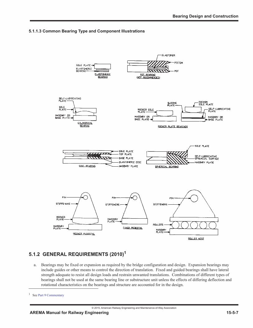
Bearing Design and Construction
© 2015, American Railway Engineering and Maintenance-of-Way Association
AREMA Manual for Railway Engineering 15-5-7
1
3
4
5.1.1.3 Common Bearing Type and Component Illustrations
5.1.2 GENERAL REQUIREMENTS (2010)1
a. Bearings may be fixed or expansion as required by the bridge configuration and design. Expansion bearings may include guides or other means to control the direction of translation. Fixed and guided bearings shall have lateral strength adequate to resist all design loads and restrain unwanted translations. Combinations of different types of bearings shall not be used at the same bearing line or substructure unit unless the effects of differing deflection and rotational characteristics on the bearings and structure are accounted for in the design.
1 See Part 9 Commentary
Steel Structures
© 2015, American Railway Engineering and Maintenance-of-Way Association
15-5-8 AREMA Manual for Railway Engineering
b. Bearings shall be designed to resist the loads and accommodate the movements stipulated herein. The most adverse combination of loads and movements shall be used for design. No damage to bridge span, bearings, or substructure due to joint or bearing movements shall be permitted under any appropriate combination of design load and movement. Horizontal forces and moments induced in the bridge by restraint of movement at the bearings shall be taken into account in the design of the bridge and the bearings. They should be determined using the calculated movements and the bearing characteristics given in Sections 5.2 through 5.7. It is recommended that all bearing design requirements be tabulated in a rational form to substantiate bearing type selection.
c. Design of bearings shall be such as to allow for expansion and contraction of the spans resulting from change in temperature at the rate of 1 inch (25 mm) in 100 feet (30 000 mm) for Minimum Service Temperature1 Zone 1 and 1-1/4 inch (30 mm) in 100 feet (30 000 mm) for Minimum Service Temperature Zones 2 and 3. Provisions shall also be made for change in length of the span resulting from live load. In steel spans more than 300 feet (90 000 mm) long, allowance shall be made for expansion of the floor system. Due consideration shall be given to the effects of lateral thermal movement for structures wider than 40 feet (12 000 mm).
d. Bearings and ends of spans shall be securely anchored against lateral and vertical movement as stipulated in Article 5.3.7. The Engineer may waive the requirement for vertical restraint of concrete spans.
e. Bearings for spans of less than 50 feet (15 000 mm) need not use radial/spherical surfaces or other special mechanisms to accommodate rotation due to live load deflection of the span, provided that the structural system otherwise permits adequate rotation.
f. Bearings for spans of 50 feet (15 000 mm) or greater shall have provision to accommodate rotation due to deflection of the span. This requirement can be accommodated by use of a type of bearing employing a hinge, curved bearing plate or rocker plate, elastomeric pad, or pin arrangement.
g. End bearings subject to both longitudinal and transverse rotation shall consist of elastomeric or multi-rotational bearings.
h. Due consideration shall be given to bearing stability under seismic loading in the selection of bearing type.
i. Bearings on masonry should be raised above the bridge seat by masonry plates, pedestals or bolsters. The Engineer may waive this requirement for elastomeric bearings.
j. Provision for the replacement of bearings shall be considered in the design.
k. When directed or authorized by the Railroad, bearings may incorporate special devices to attenuate the transfer of horizontal forces such as braking, traction and seismic loads, to the substructure. These devices may transmit forces past weak or flexible substructures and through adjacent spans into stronger substructure elements. They may allow controlled differential displacements between the span and the substructure and may also include energy dissipation mechanisms. Such devices must not prevent the proper transfer of Dead, Live, Impact, Centrifugal, and Wind loadings to the substructure, nor may they appreciably restrict thermal expansion and contraction of the spans.
5.1.3 EXPANSION BEARINGS (2007)
a. The expansion end of spans of 70 feet (21 000 mm) or less may be designed to accommodate movement through the use of low friction sliding surfaces or elastomeric pads.
b. The expansion end of spans longer than 70 feet (21 000 mm) shall be supported by bearings employing rollers, rockers, reinforced elastomeric pads, or low friction sliding surfaces designed to accommodate larger longitudinal movements.
1 See Commentary, Article 9.1.2.1d and e.
Bearing Design and Construction
© 2015, American Railway Engineering and Maintenance-of-Way Association
AREMA Manual for Railway Engineering 15-5-9
1
3
4
c. Expansion bearings shall be capable of accommodating the full anticipated longitudinal movement plus an allowance for construction tolerances. The minimum construction tolerance shall be one-half inch (13 mm) for every 100 feet (30 000 mm) of span length but shall not be less than one inch (25 mm).
5.1.4 FIXED BEARINGS (2004) R(2012)
a. The fixed end of spans shall be securely anchored to the substructure as stipulated in Article 5.3.7 to prevent horizontal movement.
b. Span rotation shall be accommodated as stipulated in the provisions of Article 5.1.2 e, f and g.
5.1.5 BEARING SELECTION CRITERIA (2010)1
a. Each type of bearing system or component has differing characteristics and capacities to accommodate or restrain translational and rotational movements and to resist vertical and horizontal loads. The bearing type chosen for a particular application must have adequate load and movement capabilities. Table 15-5-1 may be used as a guide for selecting appropriate bearing types for each application. Commentary Article 9.5.1.5.a provides additional insight into typical movement capabilities of the various bearing types.
b. Bearing types with an “R” listed in Table 15-5-1, may be suitable for the application but require special considerations or additional elements such as sliders or guideways to accomodate or control movements; or pintles, link bars, or other restrainers to provide load resistance.
c. Pot-type multi-rotational bearings should not be used for support of railroad bridges due to concerns over large cyclical live load deformations and rotation.
d. Due to thickness, rotation and compressive deflection limitations stipulated in Section 5.6, the size of elastomeric bearings is limited for applications with rotation. For preliminary bearing selection, unless approved by the Engineer, the width of elastomeric bearings in the direction perpendicular to the axis of rotation shall be limited to 12 inches (300 mm) for plain elastomeric pads and to 24 inches (600 mm) for reinforced elastomeric bearings.
1 See Part 9 Commentary
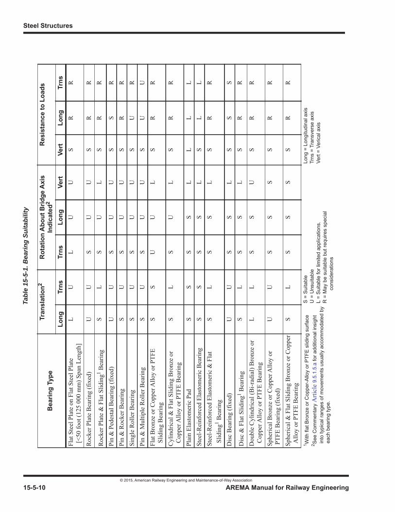
Steel Structures
© 2015, American Railway Engineering and Maintenance-of-Way Association
15-5-10 AREMA Manual for Railway Engineering
Tabl
e 15
-5-1
. Bea
ring
Suita
bilit
y
Bea
ring
Type
Tran
slat
ion2
Rot
atio
n A
bout
Brid
ge A
xis
Indi
cate
d2R
esis
tanc
e to
Loa
ds
Long
Trns
Trns
Long
Vert
Vert
Long
Trns
Flat
Ste
el P
late
on
Flat
Ste
el P
late
[
<50
foot
(125
000
mm
) Spa
n Le
ngth
]L
UL
UU
SR
R
Roc
ker P
late
Bea
ring
(fix
ed)
UU
SU
US
RR
Roc
ker P
late
& F
lat S
lidin
g1 Bea
ring
SL
SU
LS
RR
Pin
& P
edes
tal B
earin
g (f
ixed
)U
US
UU
SS
RPi
n &
Roc
ker B
earin
gS
US
UU
SR
RSi
ngle
Rol
ler B
earin
gS
US
UU
SU
RPi
n &
Mul
tiple
Rol
ler B
earin
gS
US
UU
SU
UFl
at B
ronz
e or
Cop
per A
lloy
or P
TFE
Slid
ing
Bea
ring
SS
UU
LS
RR
Cyl
indr
ical
& F
lat S
lidin
g B
ronz
e or
Cop
per A
lloy
or P
TFE
Bea
ring
SL
SU
LS
RR
Plai
n El
asto
mer
ic P
adS
SS
SL
LL
LSt
eel-R
einf
orce
d El
asto
mer
ic B
earin
gS
SS
SL
SL
LSt
eel-R
einf
orce
d El
asto
mer
ic &
Fla
t S
lidin
g1 Bea
ring
SL
SS
LS
RR
Dis
c B
earin
g (f
ixed
)U
US
SL
SS
S
Dis
c &
Fla
t Slid
ing1 B
earin
gS
LS
SL
SR
R
Dou
ble
Cyl
indr
ical
(Bi-r
adia
l) B
ronz
e or
Cop
per A
lloy
or P
TFE
Bea
ring
LL
SS
US
RR
Sphe
rical
Bro
nze
or C
oppe
r Allo
y or
PTF
E B
earin
g (f
ixed
)U
US
SS
SR
R
Sphe
rical
& F
lat S
lidin
g B
ronz
e or
Cop
per
Allo
y or
PTF
E B
earin
gS
LS
SS
SR
R
1 With
flat
Bro
nze
or C
oppe
r-Allo
y or
PTF
E sl
idin
g su
rface
2 See
Com
men
tary
Arti
cle
9.5.
1.5.
a fo
r add
ition
al in
sigh
t i
nto
typi
cal r
ange
s of
mov
emen
ts u
sual
ly a
ccom
mod
ated
by
eac
h be
arin
g ty
pe.
S =
Suita
ble
U =
Uns
uita
ble
L =
Suita
ble
for l
imite
d ap
plic
atio
ns.
R =
May
be
suita
ble
but r
equi
res
spec
ial
co
nsid
erat
ions
Long
= L
ongi
tudi
nal a
xis
Trns
= T
rans
vers
e ax
isVe
rt =
Veric
al a
xis
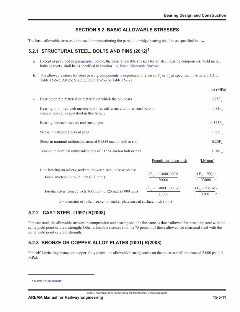
Bearing Design and Construction
© 2015, American Railway Engineering and Maintenance-of-Way Association
AREMA Manual for Railway Engineering 15-5-11
1
3
4
SECTION 5.2 BASIC ALLOWABLE STRESSES
The basic allowable stresses to be used in proportioning the parts of a bridge bearing shall be as specified below.
5.2.1 STRUCTURAL STEEL, BOLTS AND PINS (2012)1
a. Except as provided in paragraph c below, the basic allowable stresses for all steel bearing components, weld metal, bolts or rivets, shall be as specified in Section 1.4, Basic Allowable Stresses.
b. The allowable stress for steel bearing components is expressed in terms of Fy or Fu as specified in Article 5.3.2.1,Table 15-5-2, Article 5.3.2.2, Table 15-5-3 or Table 15-1-1.
psi (MPa)
c. Bearing on pin material or material on which the pin bears 0.75Fy
Bearing on milled web members, milled stiffeners and other steel parts in 0.83Fycontact, except as specified in this Article
Bearing between rockers and rocker pins 0.375Fy
Stress in extreme fibers of pins 0.83Fy
Shear in nominal unthreaded area of F1554 anchor bolt or rod 0.20Fu
Tension in nominal unthreaded area of F1554 anchor bolt or rod 0.38Fu
Pounds per linear inch (kN/mm)
Line bearing on rollers, rockers, rocker plates, or base plates:
For diameters up to 25 inch (600 mm)
For diameters from 25 inch (600 mm) to 125 inch (3 000 mm)
5.2.2 CAST STEEL (1997) R(2008)
For cast steel, the allowable stresses in compression and bearing shall be the same as those allowed for structural steel with thesame yield point or yield strength. Other allowable stresses shall be 75 percent of those allowed for structural steel with thesame yield point or yield strength.
5.2.3 BRONZE OR COPPER-ALLOY PLATES (2001) R(2008)
For self-lubricating bronze or copper-alloy plates, the allowable bearing stress on the net area shall not exceed 2,000 psi (14MPa).
1 See Part 9 Commentary
d = diameter of roller, rocker, or rocker plate curved surface; inch (mm)
Fy 13000– 600d20000
--------------------------------------------Fy 90– d
33000--------------------------
Fy 13000– 3000 d20000
---------------------------------------------------Fy 90– d
1300------------------------------
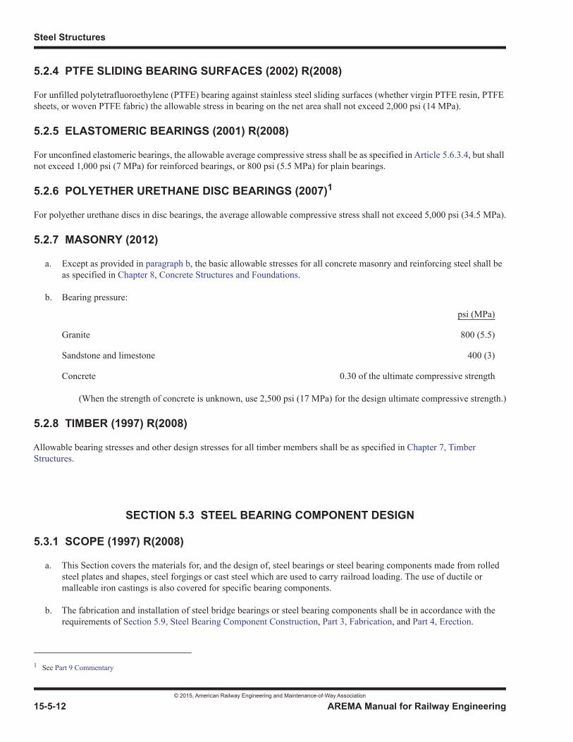
Steel Structures
© 2015, American Railway Engineering and Maintenance-of-Way Association
15-5-12 AREMA Manual for Railway Engineering
5.2.4 PTFE SLIDING BEARING SURFACES (2002) R(2008)
For unfilled polytetrafluoroethylene (PTFE) bearing against stainless steel sliding surfaces (whether virgin PTFE resin, PTFE sheets, or woven PTFE fabric) the allowable stress in bearing on the net area shall not exceed 2,000 psi (14 MPa).
5.2.5 ELASTOMERIC BEARINGS (2001) R(2008)
For unconfined elastomeric bearings, the allowable average compressive stress shall be as specified in Article 5.6.3.4, but shall not exceed 1,000 psi (7 MPa) for reinforced bearings, or 800 psi (5.5 MPa) for plain bearings.
5.2.6 POLYETHER URETHANE DISC BEARINGS (2007)1
For polyether urethane discs in disc bearings, the average allowable compressive stress shall not exceed 5,000 psi (34.5 MPa).
5.2.7 MASONRY (2012)
a. Except as provided in paragraph b, the basic allowable stresses for all concrete masonry and reinforcing steel shall be as specified in Chapter 8, Concrete Structures and Foundations.
b. Bearing pressure:
psi (MPa)
Granite 800 (5.5)
Sandstone and limestone 400 (3)
Concrete 0.30 of the ultimate compressive strength
(When the strength of concrete is unknown, use 2,500 psi (17 MPa) for the design ultimate compressive strength.)
5.2.8 TIMBER (1997) R(2008)
Allowable bearing stresses and other design stresses for all timber members shall be as specified in Chapter 7, Timber Structures.
SECTION 5.3 STEEL BEARING COMPONENT DESIGN
5.3.1 SCOPE (1997) R(2008)
a. This Section covers the materials for, and the design of, steel bearings or steel bearing components made from rolled steel plates and shapes, steel forgings or cast steel which are used to carry railroad loading. The use of ductile or malleable iron castings is also covered for specific bearing components.
b. The fabrication and installation of steel bridge bearings or steel bearing components shall be in accordance with the requirements of Section 5.9, Steel Bearing Component Construction, Part 3, Fabrication, and Part 4, Erection.
1 See Part 9 Commentary
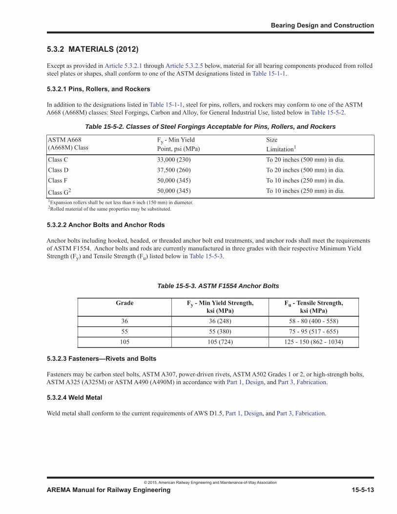
Bearing Design and Construction
© 2015, American Railway Engineering and Maintenance-of-Way Association
AREMA Manual for Railway Engineering 15-5-13
1
3
4
5.3.2 MATERIALS (2012)
Except as provided in Article 5.3.2.1 through Article 5.3.2.5 below, material for all bearing components produced from rolled steel plates or shapes, shall conform to one of the ASTM designations listed in Table 15-1-1.
5.3.2.1 Pins, Rollers, and Rockers
In addition to the designations listed in Table 15-1-1, steel for pins, rollers, and rockers may conform to one of the ASTM A668 (A668M) classes: Steel Forgings, Carbon and Alloy, for General Industrial Use, listed below in Table 15-5-2.
5.3.2.2 Anchor Bolts and Anchor Rods
Anchor bolts including hooked, headed, or threaded anchor bolt end treatments, and anchor rods shall meet the requirements of ASTM F1554. Anchor bolts and rods are currently manufactured in three grades with their respective Minimum Yield Strength (Fy) and Tensile Strength (Fu) listed below in Table 15-5-3.
5.3.2.3 Fasteners—Rivets and Bolts
Fasteners may be carbon steel bolts, ASTM A307, power-driven rivets, ASTM A502 Grades 1 or 2, or high-strength bolts, ASTM A325 (A325M) or ASTM A490 (A490M) in accordance with Part 1, Design, and Part 3, Fabrication.
5.3.2.4 Weld Metal
Weld metal shall conform to the current requirements of AWS D1.5, Part 1, Design, and Part 3, Fabrication.
Table 15-5-2. Classes of Steel Forgings Acceptable for Pins, Rollers, and Rockers
ASTM A668(A668M) Class
Fy - Min YieldPoint, psi (MPa)
SizeLimitation1
Class C 33,000 (230) To 20 inches (500 mm) in dia.Class D 37,500 (260) To 20 inches (500 mm) in dia.Class F 50,000 (345) To 10 inches (250 mm) in dia.
Class G2 50,000 (345) To 10 inches (250 mm) in dia.1Expansion rollers shall be not less than 6 inch (150 mm) in diameter.2Rolled material of the same properties may be substituted.
Table 15-5-3. ASTM F1554 Anchor Bolts
Grade Fy - Min Yield Strength,ksi (MPa)
Fu - Tensile Strength,ksi (MPa)
36 36 (248) 58 - 80 (400 - 558)55 55 (380) 75 - 95 (517 - 655)105 105 (724) 125 - 150 (862 - 1034)

Steel Structures
© 2015, American Railway Engineering and Maintenance-of-Way Association
15-5-14 AREMA Manual for Railway Engineering
5.3.2.5 Cast Steel, Ductile Iron Castings and Malleable Castings
5.3.2.5.1 Cast Steel and Ductile Iron
a. Cast steel shall conform to specifications for Mild-to-Medium Strength Carbon-Steel Castings for General Application, ASTM A27, Grade 65-35 (A27M, Grade 450-240); High Strength Steel Castings for Structural Purposes, ASTM A148 (A148M) and Corrosion-Resistant Iron-Chromium, Iron-Chromium-Nickel and Nickel-Based Alloy Castings for General Applications, ASTM A743 (A743M).
b. Ductile iron castings shall conform to ASTM A536.
5.3.2.5.2 Malleable Castings
Malleable castings shall conform to specifications for Malleable Iron Castings, ASTM A47 (A47M), Grade 32510 (22010) [minimum yield point, Fy, 32,500 psi (220 MPa)].
5.3.3 SHOES AND PEDESTALS (2001)1 R(2008)
a. Shoes and pedestals shall be designed on the assumption that the vertical load is distributed uniformly over the entire bearing surface. They shall be either made of cast steel or built-up by welding rolled steel and/or cast steel elements together.
b. Shoes and pedestals should be made of cast steel or structural steel. No part of a cast steel shoe, and no load carrying part of a welded shoe, shall be less than 1 inch (25 mm) thick.
c. In a welded shoe, the vertical load shall be carried directly in bearing between elements. Diaphragms shall be provided between web surfaces to ensure stability of component parts.
d. The difference in width and length between top and bottom bearing surfaces shall not exceed twice the vertical distance between them. For hinged bearings with pins, the vertical distance shall be measured from the centerline of pin.
e. Webs and pin holes in the webs shall be arranged to keep any eccentricity to a minimum. The net section through the hole shall provide 140 percent of the net section required for the actual stress transmitted through the pedestal or shoe. Pins shall be of sufficient length to ensure a full bearing. Pins shall be secured in position by appropriate nuts with washers. All portions of shoes and pedestals shall be secured against lateral movement of the pins.
5.3.4 ROCKER PLATES, ROCKERS AND ROLLERS (2001) R(2008)
5.3.4.1 Rocker Plates
a. Rocker plates shall be used in preference to either rockers or rollers where conditions permit. Rocker plates must be used in conjunction with a base plate. For expansion bearings, the base plate must be supported on a reinforced elastomeric pad or low friction sliding surface designed to accommodate longitudinal movements from both temperature and translations at the span bearing elevation resulting from span rotations due to span deflections. The elastomeric pad or sliding surface should only be placed at the expansion end of the span and must be designed to also accommodate the additive longitudinal movements resulting from fixed end span rotation.
b. The nominal centerline thickness of the rocker plate shall not be less than 1-1/2 inch (40 mm) and the curved surface shall be cylindrical.
1 See Part 9 Commentary
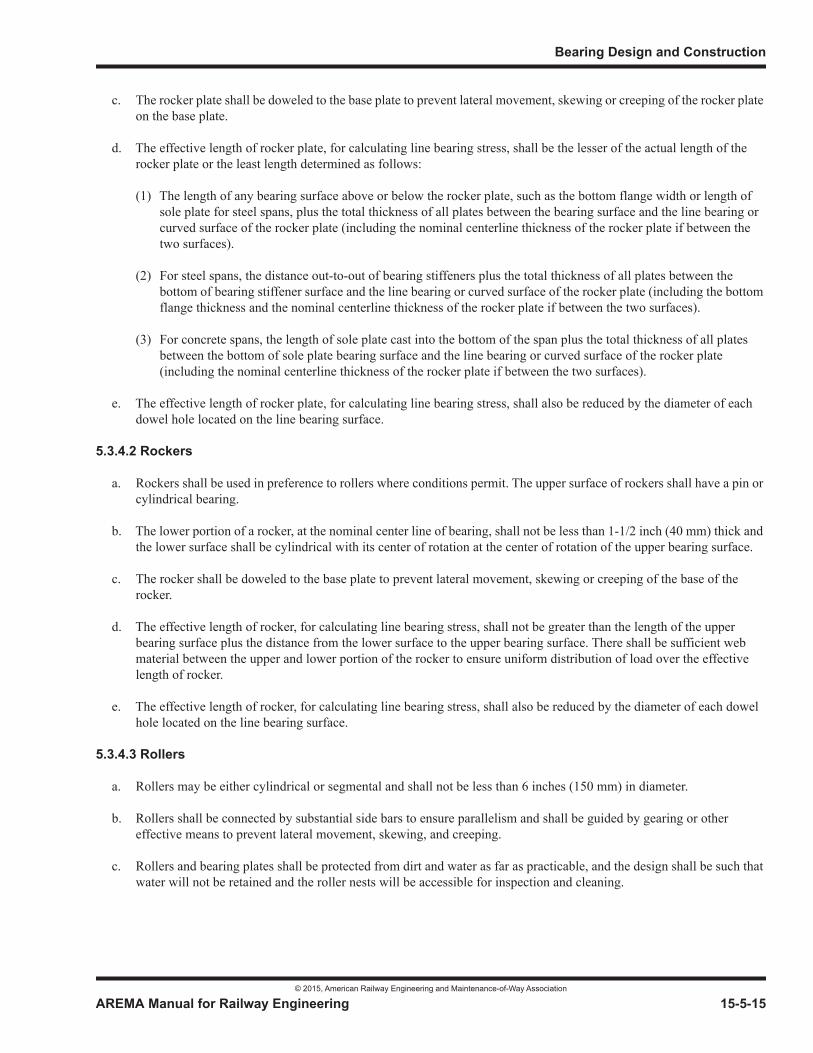
Bearing Design and Construction
© 2015, American Railway Engineering and Maintenance-of-Way Association
AREMA Manual for Railway Engineering 15-5-15
1
3
4
c. The rocker plate shall be doweled to the base plate to prevent lateral movement, skewing or creeping of the rocker plate on the base plate.
d. The effective length of rocker plate, for calculating line bearing stress, shall be the lesser of the actual length of the rocker plate or the least length determined as follows:
(1) The length of any bearing surface above or below the rocker plate, such as the bottom flange width or length of sole plate for steel spans, plus the total thickness of all plates between the bearing surface and the line bearing or curved surface of the rocker plate (including the nominal centerline thickness of the rocker plate if between the two surfaces).
(2) For steel spans, the distance out-to-out of bearing stiffeners plus the total thickness of all plates between the bottom of bearing stiffener surface and the line bearing or curved surface of the rocker plate (including the bottom flange thickness and the nominal centerline thickness of the rocker plate if between the two surfaces).
(3) For concrete spans, the length of sole plate cast into the bottom of the span plus the total thickness of all plates between the bottom of sole plate bearing surface and the line bearing or curved surface of the rocker plate (including the nominal centerline thickness of the rocker plate if between the two surfaces).
e. The effective length of rocker plate, for calculating line bearing stress, shall also be reduced by the diameter of each dowel hole located on the line bearing surface.
5.3.4.2 Rockers
a. Rockers shall be used in preference to rollers where conditions permit. The upper surface of rockers shall have a pin or cylindrical bearing.
b. The lower portion of a rocker, at the nominal center line of bearing, shall not be less than 1-1/2 inch (40 mm) thick and the lower surface shall be cylindrical with its center of rotation at the center of rotation of the upper bearing surface.
c. The rocker shall be doweled to the base plate to prevent lateral movement, skewing or creeping of the base of the rocker.
d. The effective length of rocker, for calculating line bearing stress, shall not be greater than the length of the upper bearing surface plus the distance from the lower surface to the upper bearing surface. There shall be sufficient web material between the upper and lower portion of the rocker to ensure uniform distribution of load over the effective length of rocker.
e. The effective length of rocker, for calculating line bearing stress, shall also be reduced by the diameter of each dowel hole located on the line bearing surface.
5.3.4.3 Rollers
a. Rollers may be either cylindrical or segmental and shall not be less than 6 inches (150 mm) in diameter.
b. Rollers shall be connected by substantial side bars to ensure parallelism and shall be guided by gearing or other effective means to prevent lateral movement, skewing, and creeping.
c. Rollers and bearing plates shall be protected from dirt and water as far as practicable, and the design shall be such that water will not be retained and the roller nests will be accessible for inspection and cleaning.
Steel Structures
© 2015, American Railway Engineering and Maintenance-of-Way Association
15-5-16 AREMA Manual for Railway Engineering
5.3.5 SOLE, BASE AND MASONRY PLATES (2001) R(2008)
a. Base and masonry plates shall be designed on the assumption that the vertical load is distributed uniformly over a bearing area with effective length and width as defined in paragraph b, except for eccentricity from rocker travel.
b. The effective length of the bearing area shall not be greater than the effective length of the rocker plate or rocker as defined in Article 5.3.4.1d or Article 5.3.4.2d, or the length of the roller, plus 2 times the thickness of the base plate. The effective width of the bearing area shall not be greater than 4 times the thickness of the base plate for a single roller, rocker plate or rocker, or the distance between multiple rollers plus 4 times the thickness of the base plate for roller nests.
c. For spans designed to slide on bearings with smooth surfaces without hinges, the distance from centerline of bearing to edge of masonry plate, measured parallel with the track, shall not be more than 2 times the thickness of the plate plus 4 inches (100 mm).
d. Sole plates shall have a minimum thickness of 3/4 inch (20 mm).
e. Base and masonry plates shall have a minimum thickness of 1-1/2 inch (40 mm).
5.3.6 INCLINED BEARINGS (1997) R(2008)
For spans on an inclined grade and without hinged bearings, the sole plates shall be beveled so that the bottom of the sole plateis level, unless the bottom of the sole plate is radially curved. All other bearing plate and masonry surfaces shall be made level.
5.3.7 ANCHOR BOLTS AND RODS (2012)
a. Anchorages shall be designed to transfer the applicable horizontal and vertical forces. Provision for anchorage of spans to the substructure shall be as follows:
(1) Steel trusses, steel girders, steel rolled beam spans, steel masonry plates and timber beams shall be securely anchored to the substructure with anchor bolts.
(2) Except when waived by the Engineer, concrete spans shall be anchored to the substructure with anchor bolts or anchor rods.
b. Except as provided in paragraph e below, anchor bolts shall not be less than 1-1/4 inch (32 mm) diameter. There shall be washers under the nuts. Anchor bolt holes in pedestals, masonry plates, or sole plates shall be 3/8 inch (10 mm) larger in diameter than the bolts. At expansion bearings the holes in the sole plates may be slotted.
c. Except as provided in paragraph e below, anchor bolts and anchor rods shall extend at least 12 inches (300 mm) into masonry substructures. Those that are required to resist uplift shall be designed to engage a substantial mass of masonry, the weight of which is at least 1.5 times the computed uplift at the bearing.
d. Anchor bolts and anchor rods may be cast into the substructure concrete or may be installed in holes drilled into the masonry substructure. Anchor bolts and anchor rods shall be swedged, threaded or shall have rolled deformations to secure a satisfactory bond with the material in which they are embedded.
e. In addition to meeting the allowable stress requirements of Article 5.2.1c, the following are minimum requirements for anchorages at each bearing:
(1) For timber elements:
Spans 50 feet (15 000 mm) or less: In accordance with Chapter 7, Timber Structures.
Bearing Design and Construction
© 2015, American Railway Engineering and Maintenance-of-Way Association
AREMA Manual for Railway Engineering 15-5-17
1
3
4
Spans greater than 50 feet (15 000 mm) to 100 feet (30 000 mm): 2 anchor bolts.
Spans greater than 100 feet (30 000 mm) to 150 feet (46 000 mm): 2 anchor bolts, 1-1/2 inch (40 mm) in diameter, embedded 15 inches (400 mm) in masonry substructures.
Spans greater than 150 feet (46 000 mm): 4 anchor bolts, 1-1/2 inch (40 mm) in diameter, embedded 15 inches (400 mm) in masonry substructures, or equivalent.
(2) For concrete spans:
For slab and double box beams: 2 anchor rods per slab or beam end.
For multiple single box beams: 1 anchor rod per beam end.
For I-beams: 2 anchor bolts per beam end.
(3) For steel spans:
For steel rolled beam spans: 2 anchor bolts.
For steel trusses or steel girders:
Spans 100 feet (30 000 mm) or less: 2 anchor bolts.
Spans greater than 100 feet (30 000 mm) to 150 feet (46 000 mm): 2 anchor bolts, 1-1/2 inch (40 mm) in diameter, embedded 15 inches (400 mm) in masonry substructures.
Spans greater than 150 feet (46 000 mm): 4 anchor bolts, 1-1/2 inch (40 mm) in diameter, embedded 15 inches (400 mm) in masonry substructures, or equivalent.
5.3.8 CENTRAL GUIDE KEYS AND GUIDE BARS (2001) R(2008)
a. Central guide keys may be made integral by machining from the solid. Where a separate key or guide bar is used it shall be fitted in a keyway slot machined into the plate to give a press fit and bolted or welded to the plate to resist overturning.
b. Guide bars may be made integral by machining from the solid or may be fabricated from bars and welded or bolted to resist overturning.
c. Guide bars and central guide keys shall be designed for the specified horizontal forces, but not for less than 10% of the vertical capacity of the bearing.
d. The total clearance between the key/guide bars and guided members shall be 1/8 inch (3 mm) maximum.
e. Guided members must have their contact area within the guide bars in all operating positions.
f. Guiding off the fixed base or any extensions of it, where transverse rotation is anticipated, shall be avoided.
Steel Structures
© 2015, American Railway Engineering and Maintenance-of-Way Association
15-5-18 AREMA Manual for Railway Engineering
SECTION 5.4 BRONZE OR COPPER-ALLOY SLIDING EXPANSION BEARING DESIGN
5.4.1 SCOPE (2000) R(2008)
a. This Section covers the materials for, and the design of, self-lubricating bronze or copper-alloy sliding expansion bearing plates and the permanent solid lubricating material compressed into trepanned recesses in the upper and/or lower sliding surfaces.
b. The fabrication and installation of self-lubricating bronze or copper-alloy sliding expansion bearing plates shall be in accordance with the requirements of Section 5.10.
5.4.2 MATERIALS (2000) R(2008)
5.4.2.1 Bronze Bearing And Expansion Plates
Bronze bearing and expansion plates shall conform to the Standard Specification for Bronze Castings for Bridges and Turntables, ASTM B22. Alloy C91100 shall be furnished unless otherwise specified by the Engineer.
5.4.2.2 Copper-Alloy Bearing And Expansion Plates
Copper-Alloy bearing and expansion plates shall conform to the Standard Specification for Wrought Copper-Alloy Bearing and Expansion Plates and Sheets for Bridge and Other Structural Uses, ASTM B100. Alloy C51000 or C51100 shall be furnished unless otherwise specified by the Engineer.
5.4.2.3 Solid Lubricant
Solid lubricant shall consist of a combination of solids having non-deteriorating characteristics, as well as lubricating qualitiesand shall be capable of withstanding long term atmospheric exposure, de-icing materials and water. Molybdenum disulfide and other ingredients which may promote electrolytic or chemical action between the bearing elements shall not be used.Shellac, tars and asphalts, and petroleum solvents shall not be used as binders.
5.4.3 DESIGN (2006)1 R(2012)
a. Bronze or copper-alloy sliding plates shall be chamfered at the edges. They shall be held securely in position, usually with machine screws or by being inset into the metal of the pedestals or bearing plates. Provisions shall be made against any accumulation of debris which may obstruct free movement of the span.
b. The minimum design static coefficient of friction shall be 0.10.
c. Bearings with bronze or copper-alloy sliding elements shall incorporate a sole plate and masonry plate designed in accordance with Article 5.3.5 and Article 5.3.6.
d. Masonry plates in bearings with bronze or copper-alloy sliding elements shall be bedded on a minimum 1/4 inch (6 mm) thick preformed fabric or plain elastomeric pad. When nominal transverse rotation of the sole plate or bearing is expected, such as that due to deflection of a through structure floor system, masonry plates in bearings with bronze or copper-alloy sliding elements shall be bedded on a minimum 1/2 inch (13 mm) thick preformed fabric or plain elastomeric pad. Bedding pads shall be designed in accordance with Section 5.6 of this Chapter. Bedding pads shall rest directly on the substructure and shall meet the requirements of Article 5.9.4.4b or Article 5.9.4.4e.
1 See Part 9 Commentary
Bearing Design and Construction
© 2015, American Railway Engineering and Maintenance-of-Way Association
AREMA Manual for Railway Engineering 15-5-19
1
3
4
SECTION 5.5 PTFE SLIDING BEARING SURFACE DESIGN
5.5.1 SCOPE (2002) R(2008)
a. This Section covers the materials for, and the design of, self-lubricating polytetrafluoroethylene (PTFE) sliding expansion bearing surfaces and the mating stainless steel or other hard corrosion resistant polished surface against which the PTFE expansion bearing material slides.
b. Proprietary PTFE fixed and expansion bearings may be used if, in the opinion of the Engineer, and substantiated either by tests or experience, they meet design requirements.
c. The fabrication and installation of PTFE sliding expansion bearing surfaces shall be in accordance with the requirements of Section 5.11.
5.5.2 MATERIALS (2007)
5.5.2.1 PTFE Sliding Surfaces
a. PTFE sliding surfaces shall be virgin unfilled resin, unfilled PTFE sheets or unfilled PTFE fabric. Sheet PTFE may contain dimples.
b. Filler material, such as milled glass fibers or carbon shall not be used in railroad bridge PTFE sliding surfaces.
c. PTFE resin shall be virgin material (not reprocessed) meeting the requirements of ASTM D4894. Specific Gravity shall be between 2.13 and 2.19. Melting point shall be 621°F±18 (327°C±10).
d. Finished unfilled PTFE sheet shall be made of virgin PTFE resin, shall be in accordance with ASTM D3294, Type II, Grade 1, Class C and shall conform to the following requirements:
e. Dimples in dimpled PTFE sheet shall have a diameter that does not exceed 5/16 inch (8 mm) at the surface of the PTFE sheet and their depth shall not be less than 0.8 inches (2 mm) and not more than half the thickness of the PTFE sheet.The dimples shall be uniformly distributed over the surface area and shall cover more than 20% but less than 30% of the area. If specified in the contract requirements, the dimples shall contain a lubricant. The lubricant shall be silicone grease which conforms to military specification MIL-S-8660.
f. PTFE fabric shall be manufactured from virgin PTFE oriented monofilament fibers and other fibers as approved by the Engineer and required by proprietary designs. PTFE fibers shall conform to the following requirements:
g. PTFE fabric shall be capable of carrying unit loads of 10,000 psi (70 MPa) without cold flow.
h. Adhesive material, when used to bond PTFE sheet or fabric to a substrate material, shall be an epoxy resin meeting the requirements of Federal Specification MMM-A-134, FEP film or equal, as approved by the Engineer.
Tensile Strength ASTM D4894 2,800 psi (20 MPa) (minimum)Elongation ASTM D4894 200% (minimum)
Tensile Strength ASTM D2256 24,000 psi (170 MPa) (minimum)Elongation ASTM D2256 35% (minimum)
Steel Structures
© 2015, American Railway Engineering and Maintenance-of-Way Association
15-5-20 AREMA Manual for Railway Engineering
5.5.2.2 Stainless Steel Mating Surface
a. Sheet stainless steel mating surfaces shall conform to ASTM A167 or A240 Type 304.
b. Welded stainless steel overlay shall be produced using Type 309L electrodes.
5.5.3 DESIGN (2006)1 R(2012)
5.5.3.1 General
a. PTFE sliding surfaces are intended to translate or rotate by the sliding of a self-lubricating PTFE surface across a smooth hard mating surface, preferably stainless steel or other equally corrosion resistant material. A PTFE surface sliding against another PTFE surface shall not be used.
b. Expansion bearings having PTFE sliding surfaces shall not be used without provision for a minimum rotation of 0.015 radians, to prevent excessive local stresses on the PTFE sliding surface. Rotation shall be considered the sum of live load rotation, changes in camber during construction, and misalignment of the bearing seats due to construction tolerances. The design shall include a compensating provision for grade as stipulated in Section 5.3.6. Provisions for rotation may be accomplished with a hinge, rocker, rocker plate, curved sliding surface, elastomeric pad or other means.
c. The minimum design static coefficient of friction (whether virgin PTFE resin, PTFE sheets, or woven PTFE fabric) is a function of the design bearing pressure and shall be determined using straight-line interpolation between the following limits:
d. Holes or slots shall not be used in the sliding surfaces.
e. When PTFE is used on guiding surfaces it shall be designed to carry the greater of 5% of the dead load carried by the bearing assembly or the maximum combined transverse loads as specified in Section 1.3 of this chapter, Chapter 8, Concrete Structures and Foundations or Chapter 9, Seismic Design for Railway Structures. PTFE used on a guiding surface and the stainless steel or other mating surface shall meet all design requirements specified herein and shall contain an ultraviolet (UV) inhibitor or screen.
5.5.3.2 PTFE Sliding Surfaces and Backing Substrate
a. PTFE sliding surfaces shall have the following minimum and maximum thickness under the application of 2,000 psi (14 MPa) load:
1 See Part 9 Commentary
Bearing Pressure Coefficient of Friction500 psi (4 MPa) 0.082,000 psi (14 MPa) 0.06
Unfilled PTFE cast against 1/32 in. (1 mm) minimum a backing substrate 3/32 in. (2 mm) maximum
Unfilled Sheet PTFE 1/8 in. (3 mm) minimum3/16 in. (5 mm) maximum
Bearing Design and Construction
© 2015, American Railway Engineering and Maintenance-of-Way Association
AREMA Manual for Railway Engineering 15-5-21
1
3
4
b. PTFE sheet shall be epoxy-bonded into a square-edged recess 1/16 in. (1.5 mm) deep. If sheet PTFE is used for guided surfaces, it shall be pigmented.
c. PTFE fabric shall be epoxy-bonded, or epoxy-bonded and mechanically fastened, to the substrate using a system that prevents migration of epoxy through the fabric. The fabric-substrate bond shall be capable of withstanding a shear force equal to 10 percent of the perpendicular or normal applied loading without delamination in addition to the shear force developed as a result of the natural bearing friction. Any edges, other than the selvage, shall be oversewn or recessed so that no cut fabric edges are exposed. Fabric PTFE sliding surfaces shall, in the free state, be a minimum of 1/16 in. (1.5 mm) thick when measured in accordance with ASTM D1777.
d. The substrate or back-up material to which the PTFE sliding surface is bonded shall be a rigid material capable of resisting any bending stresses to which the sliding surfaces may be subjected. If the other side of the back-up material is to be bonded to an elastomeric pad, the back-up material must have sufficient tensile strength to restrain the elastomeric pad. The elastomeric pad must be sufficiently hard to allow sliding of the PTFE contact surface, perferably at least 70 durometer hardness.
e. Welding to a steel substrate plate that has a bonded PTFE surface may be permitted providing welding procedures are established which restrict the maximum temperature reached by the bond area to less than 300°F (150°C) as determined by temperature indicating wax pencils or other suitable means.
5.5.3.3 Stainless Steel or Other Mating Surface
a. The mating surface to the PTFE shall be an accurate flat, cylindrical, or spherical surface as required by the design and shall have minimum Brinell hardness of 125.
b. Stainless steel or other mating surfaces shall be rolled or polished as necessary to produce a surface finish less than 20 microinches (0.5 m) root mean square (rms) and to meet the friction requirements of Section 5.11.1(c).
c. The mating surface shall completely cover the PTFE surface in all operating positions plus one inch (25 mm) in each direction of movement.
d. Wherever possible, the mating surface shall be at the top (face down) or otherwise oriented so that sliding movements will cause dirt and dust accumulation to fall from the mating surface.
e. Sheet stainless steel mating surfaces shall be 20 gage minimum thickness and shall be connected to its backing substrate by a continuous weld around the entire perimeter. Intermittent interior spot-welding may also be used in addition to the perimeter weld. The stainless steel sheet shall be in full contact with the substrate.
f. Welded stainless steel overlay shall be a minimum of 3/32 in. (2 mm) thick after welding, grinding and polishing.
5.5.3.4 Sole and Masonry Plates
a. Bearings with PTFE sliding elements shall incorporate a sole plate and masonry plate designed in accordance with Article 5.3.5 and Article 5.3.6.
b. Masonry plates in bearings with PTFE sliding elements shall be bedded on a minimum 1/4 inch (6 mm) thick preformed fabric or plain elastomeric pad. When nominal transverse rotation of the sole plate or bearing is expected, such as that due to deflection of a through structure floor system, masonry plates in bearings with PTFE sliding elements shall be bedded on a minimum 1/2 inch (13 mm) thick preformed fabric or plain elastomeric pad. Bedding
Fabric containing unfilled 1/32 in. (1 mm) minimum PTFE fibers 1/8 in. (3 mm) maximum
Steel Structures
© 2015, American Railway Engineering and Maintenance-of-Way Association
15-5-22 AREMA Manual for Railway Engineering
pads shall be designed in accordance with Section 5.6 of this Chapter. Bedding pads shall rest directly on the substructure and shall meet the requirements of Section 5.9.4.4b or Section 5.9.4.4e.
SECTION 5.6 ELASTOMERIC BEARING DESIGN
5.6.1 SCOPE (1999) R(2008)
a. This Section covers the materials for, and the design of, plain and reinforced elastomeric bearings made from polyisoprene (natural rubber), polychloroprene (neoprene) and plain bearings made from polyurethane which are used to carry railroad loading. (Reference 121, 122, and 135)
b. Cushioning pads, used to provide a smooth, even bearing surface, are not covered in this recommended practice since they are very thin and are not designed to translate or to withstand the loads without failure.
c. The fabrication and installation of elastomeric bridge bearings shall be in accordance with the requirements of Section 5.12.
5.6.2 MATERIALS (2001) R(2008)
5.6.2.1 Elastomer
a. The elastomeric compound shall be specified by the Engineer and shall be 100 percent virgin polyisoprene (natural rubber), virgin crystallization-resistant polychloroprene (neoprene), or cast polyurethane meeting the requirements of Table 15-5-4. When test specimens are cut from the finished product, a ten percent variation in physical properties shall be allowed.
b. Material with a nominal hardness greater than 60 durometer shall not be used in reinforced bearings.
5.6.2.2 Steel Reinforcement
Steel reinforcement for reinforced elastomeric bearings shall be not less than 0.0598 inch (1.5 mm) thick, and shall be rolled from mild steel sheet conforming to ASTM A1011 (A1011M), Grade 36; or ASTM A1008 (A1008M), Grade D unless otherwise specified by the Engineer.
5.6.2.3 External Steel Load Plates
a. Elastomeric bridge bearings may have external steel load plates bonded to the upper and/or lower surfaces. Such load plates shall be at least as large as the elastomer layer to which they are bonded. Steel load plates shall be tapered, if necessary, to ensure full bearing contact between non-parallel load surfaces. Tapered layers of elastomer are not permitted.
b. External steel load plates shall meet the requirements of Part 1, Design, except as modified by Section 5.3.
5.6.3 DESIGN (2004) R(2012)
This section covers the design of plain pads (consisting of elastomer only) and reinforced bearings (consisting of layers of elastomer restrained at their interfaces by integrally bonded steel reinforcement).
Bearing Design and Construction
© 2015, American Railway Engineering and Maintenance-of-Way Association
AREMA Manual for Railway Engineering 15-5-23
1
3
4
5.6.3.1 General
a. The size of elastomeric bearings shall be such that the external steel load plate and/or elastomer surfaces are in full contact with the loaded surface under all loading conditions.
b. The properties of elastomeric compounds depend on their constituent elements. Where shear modulus or creep deflection properties are specified or known for the specific elastomer of which the bearings are to be made, they should be used in the design. Otherwise the values used shall be those from the applicable range given in Table 15-5-4which provide the least favorable results. Values for intermediate hardness may be obtained by interpolation. The hardness grade (durometer) of the elastomer shall be selected on the basis of the requirements of Section 5.12 and the environmental conditions anticipated at the bridge site. The shear modulus shall be determined using the test specified in Sections 5.12.9 and 5.12.10. Unless otherwise specified, elastomeric bearings shall be made from a 60 durometer rubber or neoprene elastomer or a 90 durometer polyurethane elastomer.
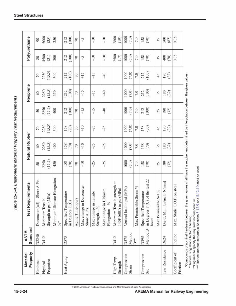
Steel Structures
© 2015, American Railway Engineering and Maintenance-of-Way Association
15-5-24 AREMA Manual for Railway Engineering
Tabl
e 15
-5-4
. Ela
stom
eric
Mat
eria
l Pro
pert
y Te
st R
equi
rem
ents
Mat
eria
lPr
oper
tyA
STM
Stan
dard
Test
Req
uire
men
tsN
atur
al R
ubbe
rN
eopr
ene
Poly
uret
hane
Har
dnes
sD
2240
Dur
omet
er (±
5)—
Shor
e A P
ts.
5060
7050
6070
8090
Phys
ical
Prop
ertie
sD
412
Min
imum
Ten
sile
Stre
ngth
in p
si (M
Pa)
2250
(15.
5)22
50(1
5.5)
2250
(15.
5)22
50(1
5.5)
2250
(15.
5)22
50(1
5.5)
4500
(31)
5000
(35)
Min
imum
Ulti
mat
e El
onga
tion—
%*
450
400
300
400
350
300
300
250
Hea
t Agi
ngD
573
Spec
ified
Tem
pera
ture
in
Deg
rees
F (C
)15
8(7
0)15
8(7
0)15
8(7
0)21
2(1
00)
212
(100
)21
2(1
00)
212
(100
)21
2(1
00)
Agi
ng T
ime-
hour
s70
7070
7070
7070
70M
ax c
hang
e in
Dur
omet
erSh
ore A
Pts
.+1
0+1
0+1
0+1
5+1
5+1
5+5
+5
Max
cha
nge
in T
ensi
le
Stre
ngth
—%
–25
–25
–25
–15
–15
–15
–10
–10
Max
cha
nge
in U
ltim
ate
Elon
gatio
n—%
–25
–25
–25
–40
–40
–40
–10
–10
Hig
h Te
mp.
St
reng
thD
412
Min
imum
Ten
sile
stre
ngth
at
140F
(60C
) in
psi (
MPa
)25
00(1
7)28
00(1
9)C
ompr
essi
onSt
rain
D57
5M
etho
dB
**
Verti
cal l
oad
in p
si (M
Pa)
1000
(7.0
)10
00(7
.0)
1000
(7.0
)10
00(7
.0)
1000
(7.0
)10
00(7
.0)
1000
(7.0
)10
00(7
.0)
Max
Per
mis
sibl
e St
rain
%7.
07.
07.
07.
07.
07.
07.
07.
0C
ompr
essi
onSe
tD
395
Met
hod
BSp
ecifi
ed T
empe
ratu
rein
Deg
rees
F (C
) of t
he te
st 2
2 ho
urs
158
(70)
158
(70)
158
(70)
212
(100
)21
2(1
00)
212
(100
)15
8(7
0)15
8(7
0)
Max
Per
mis
sibl
e Se
t %25
3545
2535
4535
35Te
ar R
esis
tanc
eD
624
Die
C, M
in. l
bs/in
ch (N
/mm
)18
0(3
2)18
0(3
2)18
0(3
2)18
0(3
2)18
0(3
2)18
0(3
2)40
0(7
0)50
0(8
7)C
oeffi
cien
t of
Fric
tion
Incl
ine
Max
. Sta
tic C
.O.F
. on
stee
l0.
350.
35
*C
ompo
unds
of n
omin
al h
ardn
ess
betw
een
the
give
n va
lues
sha
ll ha
ve th
e re
quire
men
t det
erm
ined
by
inte
rpol
atio
n be
twee
n th
e gi
ven
valu
es.
**T
este
d us
ing
shap
e fa
ctor
of b
earin
g.**
*Eng
inee
r to
spec
ify th
e re
quire
d te
st te
mpe
ratu
re.
****
The
test
met
hod
set f
orth
in S
ectio
ns 5
.12.
9 an
d 5.
12.1
0 sh
all b
e us
ed.

Bearing Design and Construction
© 2015, American Railway Engineering and Maintenance-of-Way Association
AREMA Manual for Railway Engineering 15-5-25
Abr
asio
nR
esis
tanc
eD
4060
H-1
8 W
heel
, 100
0g w
t. M
ax
Wei
ght L
oss p
er 1
000
cycl
es -
mg
2520
Hyd
roly
ticSt
abili
tyD
543
Spec
ified
Wat
er T
empe
ratu
re F
(C
)21
2(1
00)
212
(100
)A
ging
Tim
e - d
ays
3030
Max
imum
Cha
nge
in T
ensi
le
Stre
ngth
- %
-15
-15
Opt
iona
l Req
uire
men
tsO
zone
Res
ista
nce
D11
49Pa
rtial
Pre
ssur
e of
Ozo
nein
psi
(MPa
)72
50(5
0.0)
7250
(50.
0)72
50(5
0.0)
7250
(50.
0)72
50(5
0.0)
7250
(50.
0)72
50(5
0.0)
7250
(50.
0)D
urat
ion
of T
est i
n H
rs.
100
100
100
100
100
100
500
500
Test
ed a
t 20%
Stra
in 1
00°F
(3
8°C
) mou
ntin
g pr
oced
ure
AST
M D
518
Proc
edur
e A.
nocr
acks
nocr
acks
nocr
acks
nocr
acks
nocr
acks
nocr
acks
nocr
acks
nocr
acks
Shea
r Mod
ulus
Non
e***
*M
odul
us a
t 73°
F (2
3°C
) in
psi
(MPA
)95
±15
(0.7
±0.1
)14
0±20
(1.0
±0.1
)20
5±40
(1.4
±0.3
)95
±15
(0.7
±0.1
)14
0±20
(1.0
±0.1
)20
5±40
(1.4
±0.3
)55
0±15
0(3
.8±1
.0)
780±
150
(5.4
±1.0
)Lo
w T
empe
ratu
re
Prop
ertie
s***
D21
37Lo
w T
empe
ratu
re B
rittle
ness
nofa
ilure
nofa
ilure
nofa
ilure
nofa
ilure
nofa
ilure
nofa
ilure
nofa
ilure
nofa
ilure
D14
15Lo
w T
empe
ratu
re S
tiffn
ess M
ax
chan
ge in
har
dnes
s Sho
re A
Po
ints
+15
+15
+15
+15
+15
+15
+20
+20
D12
29Lo
w T
empe
ratu
re C
ompr
essi
on
Set M
ax %
6565
6565
6565
7070
Tabl
e 15
-5-4
. Ela
stom
eric
Mat
eria
l Pro
pert
y Te
st R
equi
rem
ents
Mat
eria
lPr
oper
tyA
STM
Stan
dard
Test
Req
uire
men
tsN
atur
al R
ubbe
rN
eopr
ene
Poly
uret
hane
*C
ompo
unds
of n
omin
al h
ardn
ess
betw
een
the
give
n va
lues
sha
ll ha
ve th
e re
quire
men
t det
erm
ined
by
inte
rpol
atio
n be
twee
n th
e gi
ven
valu
es.
**T
este
d us
ing
shap
e fa
ctor
of b
earin
g.**
*Eng
inee
r to
spec
ify th
e re
quire
d te
st te
mpe
ratu
re.
****
The
test
met
hod
set f
orth
in S
ectio
ns 5
.12.
9 an
d 5.
12.1
0 sh
all b
e us
ed.
(Con
tinue
d)
Steel Structures
© 2015, American Railway Engineering and Maintenance-of-Way Association
15-5-26 AREMA Manual for Railway Engineering
c. If elastomeric bearings are to be used at locations where temperatures less than -25 degrees F (-32 degrees C) can be expected for a period of several days, consideration shall be given to specifying natural rubber and to requiring special testing by the manufacturer for the temperature range expected. The increase in stiffness, embrittlement, and crystallization are areas of importance to be investigated.
5.6.3.2 Loads
“Service Load Design” shall be used for the design of elastomeric bearings.
Bearing Design and Construction
© 2015, American Railway Engineering and Maintenance-of-Way Association
AREMA Manual for Railway Engineering 15-5-27
1
3
4
5.6.3.3 Notations
A = Plan area of bearing—inch2 (mm2)aL = Relative rotation of top and bottom surfaces of bearing about an axis perpendicular to the longitudinal
axis of the bridge—radiansaW = Relative rotation of top and bottom surfaces of bearing about an axis parallel to the longitudinal axis
of the bridge—radiansD = Gross diameter of reinforcement of a circular bearing—inch (mm)dc = Instantaneous compressive deflection of bearing—inch (mm)
ds = Shear deflection of bearing excluding construction tolerance—inch (mm)
eci = Compressive strain of an individual elastomer layer [change in thickness divided by unstressed thickness]
fa = Average compressive stress on bearing caused by dead load and live load with normal impact—psi (MPa)
= P/A—psi (MPa)Fs = Shear force on bearing—lbs (N)
Fy = Yield Point of internal steel reinforcement—psi (MPa)
G = Shear modulus of elastomer at the design temperature—psi (MPa)k = Modifying factor
= 1.0 for internal layers of reinforced bearings= 1.4 for cover layers= 1.8 for plain bearings
L = Length of a rectangular bearing parallel to the longitudinal axis of the bridge. For reinforced bearings these values refer to the internal reinforcement dimensions—inch (mm).
P = Vertical load on the bearing—lbs (N)S = Shape factor of one layer of a bearing
=
=
=
T = Total elastomer thickness of bearing—inch (mm) =
ti = Actual elastomer thickness between reinforcing plates of an individual elastomer layer—inch (mm)
ts = Thickness of one internal steel reinforcement—inch (mm)
W = Width of a rectangular bearing perpendicular to the longitudinal axis of the bridge. For reinforced bearings these values refer to the internal reinforcement dimensions—inch (mm).
loaded areaeffective area free to bulge----------------------------------------------------------------
LW2ti L W+--------------------------- Rectangular Bearing
D4ti------ Circular Bearing
ti

Steel Structures
© 2015, American Railway Engineering and Maintenance-of-Way Association
15-5-28 AREMA Manual for Railway Engineering
5.6.3.4 Compressive Stress
For bearings which may experience shear deformation, the average compressive stress, fa, shall not exceed GS/k, nor shall it exceed 1,000 psi (7 MPa) for reinforced bearings, or 800 psi (5.5 MPa) for plain bearings. In bearings containing layers of different thicknesses, the value of S/k shall be taken as the smallest value obtained for the various layers of the bearing. Allowable compressive stress may be increased by 10% where shear translation is prevented or a positive slip apparatus is provided. Recommendations for a positive slip apparatus are not covered by this recommended practice. Design of a positive slip apparatus must be approved by the Engineer.
5.6.3.5 Compressive Deflection
a. Compressive deflection, dc, of the bearing shall be so limited as to ensure the serviceability of the bridge.
b. Instantaneous deflection shall be calculated as and shall be less than 0.07T or 0.125 inch (3 mm), whichever is lower.
c. Values for eci shall be obtained from design aids based on tests such as presented in Figure 15-5-1, Graph A or B, and Figure 15-5-2, Graph A, by testing, or by rational analysis.
d. The effects of compression set of the elastomer shall be added to the instantaneous deflection when considering long-term dead load deflections. They shall be computed from information specific to the elastomer compound used, if it is available; if not, the values of 25% for 50 durometer elastomer, 35% for 60 durometer elastomer, and 45% for 70 durometer elastomer may be used. For polyurethane, 35% may be used for an 80 or 90 durometer elastomer. The 0.125 in. (3 mm) limit in paragraph b does not apply for long-term dead load deflections.
e. The total compressive instantaneous deflection—excluding dead load deflection—of all elastomeric pad and bearing elements that occur between the top of deck and rigid support foundations (pads between deck slabs and girder top flanges, elastomeric bearings, elastomeric pads between masonry plates and top of masonry, etc.) shall also be calculated as and shall be less than 0.125 inch (3 mm).
5.6.3.6 Rotation
The relative rotation between top and bottom surfaces of the bearing shall be limited by
L(aL) + W(aW) 2(dc) for rectangular bearings
D[(aL)2 + (aW)2]1/2 2(dc) for circular bearings
5.6.3.7 Shear
a. The shear deformation shall be taken as the maximum possible deformation caused by creep, shrinkage, post-tensioning, live load rotation and thermal effects computed between the installation temperature and the least favorable extreme temperature, unless a positive slip apparatus is installed.
b. The bearing shall be designed so that
T 2 ds
c. The shear force induced by shear deformation is approximated by
Fs = G ds A/T
d. Variations of G with temperature shall be taken into account. Test data from the manufacturer or from special testing for the project shall be used for the design. Since the physical data can be expected to vary widely, maximum values
dc eciti=
dc eciti=
Bearing Design and Construction
© 2015, American Railway Engineering and Maintenance-of-Way Association
AREMA Manual for Railway Engineering 15-5-29
1
3
4
should be used for obtaining forces involved, and minimum values used to determine shear deflection. Design aids are given in Figure 15-5-1, Graph C, and Figure 15-5-2, Graph B, and can be used if special project values are not available.
5.6.3.8 Stability
To ensure stability, the total thickness of the bearing shall not exceed the smallest of:
L/5, W/5 or D/6 for plain bearings
L/3, W/3 or D/4 for reinforced bearings
5.6.3.9 Steel Reinforcement
a. The reinforcement must be adequate to maintain proper alignment during fabrication and to sustain the tensile stresses induced by compression of the bearing. The minimum thickness is limited to require ts 0.092 ti.
b. For these purposes, ti shall be taken as the mean thickness of the two layers of elastomer bonded to the reinforcement. The determination of the steel reinforcement thickness shall take into account an allowance for stress concentration caused by holes in the bearing. Holes are discouraged for all bearings.
5.6.3.10 Anchorage
When some combination of loads exists which causes a shear force greater than 1/5 of the simultaneously occurring compressive force, the bearing shall be secured against horizontal movement. When the bearing is attached to both top and bottom surfaces, the attachment must be such that no tension is possible in the vertical direction. When the dead load stress onthe bearing is less than 200 psi (1.4 MPa), or the horizontal loads are greater than the frictional resistance when using a coefficient of friction of 0.20, the bearing shall be restrained against horizontal movement. All anchorages shall also meet therequirements stipulated in Article 5.3.7.
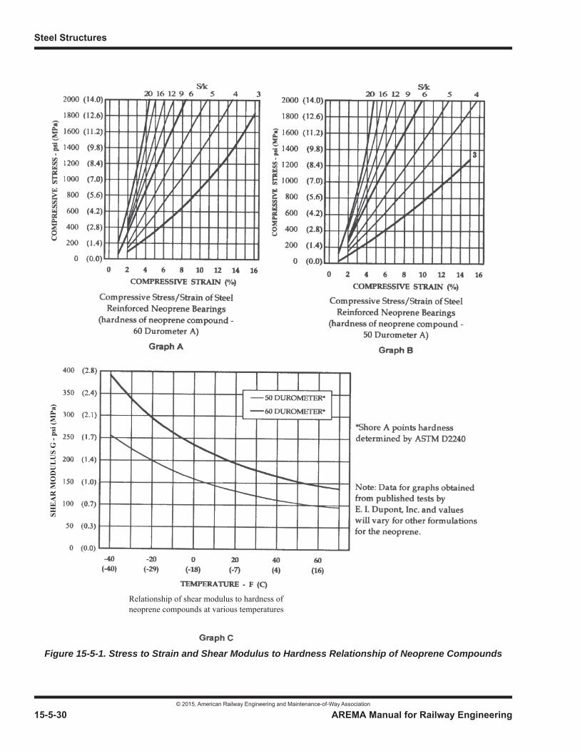
Steel Structures
© 2015, American Railway Engineering and Maintenance-of-Way Association
15-5-30 AREMA Manual for Railway Engineering
Figure 15-5-1. Stress to Strain and Shear Modulus to Hardness Relationship of Neoprene Compounds
Relationship of shear modulus to hardness of neoprene compounds at various temperatures
SHE
AR
MO
DU
LU
S G
- ps
i (M
Pa)
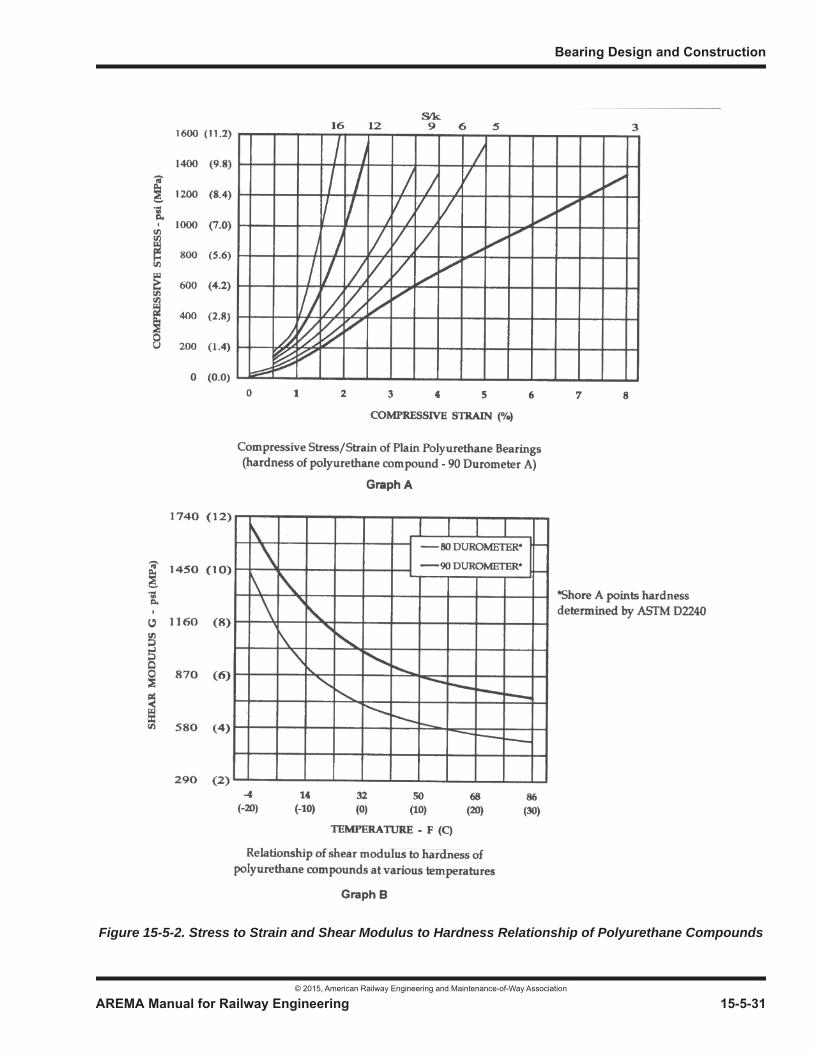
Bearing Design and Construction
© 2015, American Railway Engineering and Maintenance-of-Way Association
AREMA Manual for Railway Engineering 15-5-31
1
3
4
Figure 15-5-2. Stress to Strain and Shear Modulus to Hardness Relationship of Polyurethane Compounds

Steel Structures
© 2015, American Railway Engineering and Maintenance-of-Way Association
15-5-32 AREMA Manual for Railway Engineering
5.6.3.11 Stiffeners for Steel Girders
a. Steel girders seated on elastomeric bearings must have flanges which are stiff enough locally not to cause damage to the bearing. Any necessary stiffening may be accomplished by attaching a sole plate to the bottom flange of the girder or by vertical stiffeners connected to the girder web and flanges. The requirements of Part 1, Design, shall govern the design of steel girder stiffeners and connections.
b. Single-webbed girders symmetrical about their vertical axis and placed symmetrically on the bearing need no additional stiffening if:
bf/2tf [Fy /3.4 fa]1/2
where
c. If the requirement of paragraph b is not satisfied, it will be necessary to add two or more bearing stiffeners on each side of the girder at a spacing “a” given by the following requirement:
a [(tf)2 Fy /1.2 fa]1/2
where
5.6.3.12 Geometrics
a. Misalignment in bridge girders due to fabrication tolerance, camber, or other source, shall be considered in the bearing design or shall be accounted for with tapered sole plates or by a device which prevents eccentric loading on the bearing.
b. Bearings which are used in pairs shall be placed along an axis perpendicular to the longitudinal axis of a beam.
5.6.3.13 Alternate Design Procedures
The design of bearings by procedures other than those outlined above shall be permitted, at the discretion of the Engineer. Such procedures shall take into account the stresses and deformation in the bearing determined from a rational analysis and thedesign shall be based on the material properties pertinent to the elastomer of which the bearing is to be made. Performance shall be verified by test, using the standards of Test Criteria II certification given in Section 5.12, and, in addition, the effects of instability and fatigue shall be investigated.
bf = total flange width—inch (mm)
tf = flange thickness or combined coverplate + flange thickness—inch (mm)
Fy = yield point stress of girder steel—psi (MPa)
fa= calculated axial stress—psi (MPa)
tf = flange thickness or combined coverplate + flange thickness—inch (mm)
Fy = yield point stress of girder steel—psi (MPa)
fa= calculated axial stress—psi (MPa)
Bearing Design and Construction
© 2015, American Railway Engineering and Maintenance-of-Way Association
AREMA Manual for Railway Engineering 15-5-33
1
3
4
SECTION 5.7 MULTI-ROTATIONAL BEARING DESIGN
5.7.1 SCOPE (2007)1
a. This Section covers the materials for, and the design of, fixed and expansion disc type and spherical type multi-rotational bearings capable of accommodating rotation in multiple directions, typically both transverse and longitudinal directions. In addition, multi-rotational bearings are capable of accommodating or restraining translations in multiple directions. Multi-rotational bearings include fixed, guided expansion, and non-guided expansion configurations.
b. Proprietary multi-rotational bearings may be used if, in the opinion of the Engineer and substantiated either by tests or experience, they meet these design requirements.
c. Unless approved by the Engineer, pot type multi-rotational bearings shall not be used for support of railroad bridges.
d. The fabrication and installation of multi-rotational bearings shall be in accordance with the requirements of Section 5.13.
5.7.2 MATERIALS (2007)
a. Steel components of multi-rotational bearings shall meet the requirements of Article 5.3.2.
b. Self-lubricating bronze or copper-alloy components providing flat or spherical sliding or rotating surfaces of multi-rotational bearings, and the solid lubricant, shall meet the requirements of Article 5.4.2.
c. PTFE and mating stainless steel components providing flat or spherical sliding or rotating surfaces of multi-rotational bearings shall meet the requirements of Article 5.5.2.
d. Elastomer for disc multi-rotational bearings shall be a polyether urethane formulation conforming to the following requirements:
1 See Part 9 Commentary
Material Properties ASTMStandard
Requirements
Hardness, Shore D Durometer D2240 60[min] 65[max]Tensile stress, psi (MPa) [min] D412 @100% Elongation 2100 (14.5) @200% Elongation 3700 (25.5)Tensile strength, psi (MPa) [min] D412 5500 (38)Ultimate Elongation, % [min] D412 253Max. Compression Set, D395 22 hours @ 158°F, % 40
Steel Structures
© 2015, American Railway Engineering and Maintenance-of-Way Association
15-5-34 AREMA Manual for Railway Engineering
5.7.3 DESIGN (2014)1
5.7.3.1 General
a. Multi-rotational bearings shall be considered for the support of bridges when the following conditions are present:
(1) Curved or skewed spans and other similar structures where complex designs are required.
(2) The direction of rotation of the bridge span will vary.
(3) The direction of rotation of the bridge span can not be precisely determined.
(4) Settlement of the substructure is anticipated.
(5) Self-aligning capabilities of the bearings are required.
(6) Load and rotation eccentricity would otherwise significantly alter the net distribution of stress through the bearing and into the substructure and superstructure.
(7) Large rotational movements are anticipated.
b. Multi-rotational bearings shall be designed in accordance with the general requirements of Article 5.1.2, Article 5.1.3,and Article 5.1.4.
c. Multi-rotational bearings shall be designed in accordance with the basic allowable stress requirements of Section 5.2.
d. Except as provided in Article 5.7.3.2 through Article 5.7.3.5 below, steel components of multi-rotational bearings shall be designed in accordance with the requirements of Section 5.3.
e. Elastomer for disc type multi-rotational bearings shall be designed in accordance with Article 5.7.3.2 through Article 5.7.3.5 and Article 5.7.4 below.
f. Except as provided in Article 5.7.3.2 through Article 5.7.3.5 and Article 5.7.5 below, self-lubricating bronze or copper-alloy components providing flat or spherical sliding or rotating surfaces of multi-rotational bearings shall be designed in accordance with the requirements of Article 5.4.3.
g. Except as provided in Article 5.7.3.2 through Article 5.7.3.5 and Article 5.7.5 below, PTFE and mating stainless steel components providing flat or spherical sliding or rotating surfaces of multi-rotational bearings shall be designed in accordance with the requirements of Article 5.5.3.
h. The types of multi-rotational bearings shall not be varied along the same bearing line.
5.7.3.2 Loads2
a. The design of multi-rotational bearings shall consider the simultaneous occurrence of vertical and horizontal loads. Consideration shall be given to the following:
(1) Maximum vertical loads in combination with horizontal loads occurring simultaneously;
(2) Maximum horizontal loads in combination with vertical loads occurring simultaneously.
1 See Part 9 Commentary2 See Part 9 Commentary

Bearing Design and Construction
© 2015, American Railway Engineering and Maintenance-of-Way Association
AREMA Manual for Railway Engineering 15-5-35
1
3
4
b. Multi-rotational bearings shall be designed for a minimum horizontal load of 10% of the vertical load.
c. Frictional resistance of multi-rotational bearing sliding surfaces shall be neglected when determining horizontal load capacity.
5.7.3.3 Nomenclature
5.7.3.4 Rotational Capacity
Multi-rotational bearings shall be designed to have a rotational capacity of:
Rb = Rs + Rc + Ru
5.7.3.5 Translation Capacity
a. Fixed multi-rotational bearings shall allow rotation in any direction but shall restrain horizontal translation in the longitudinal and transverse directions.
b. Guided expansion multi-rotational bearings shall allow rotation in any direction and shall allow horizontal translation in the guided direction only. Horizontal translation in non-guided directions shall be restrained using either a guide bar or keyway system designed in accordance with Article 5.3.8. Horizontal translation in the guided direction shall be accommodated using a flat bronze or copper-alloy sliding surface designed in accordance with Section 5.4 or a PTFE sliding surface designed in accordance with Section 5.5.
C = Vertical clearance between rotating and non-rotating bearing parts of a spherical bearing - inch (mm)
Dd = Outside diameter of elastomeric disc element - inch (mm)
Ds = Projected diameter of loaded spherical segment - inch (mm)
Lh max = Maximum horizontal loading on a spherical bearing - lbs (N)
Lv min = Minimum vertical loading on a spherical bearing - lbs (N)
OD = Outside diameter of round spherical bearing surface - inch (mm)Rb = Rotation capacity to be accommodated by multi-rotational bearing - radians
Rc = Rotation induced in the multi-rotational bearing by construction tolerances - radians (0.005 radians maximum)
Rmax = Maximum radius of spherical element - inch (mm)
Rs = Anticipated rotation of the bridge superstructure in service (includes live load rotations, rotations induced by construction procedures and erection sequences, etc.) - radians
Ru = Rotational allowance for uncertainties - radians (use 0.005 radians unless an approved quality control plan justifies a smaller value)
S = Length of side of square spherical bearing surface - inch (mm)t = Thickness of elastomeric disc - inch (mm)
Deflection of elastomeric disc due to all vertical dead, live and impact loads at zero rotation - inch (mm)
=
max = t = Compressive strain of elastomeric disc due to all vertical dead, live and impact loads at zero rotation, not including long term creep.

Steel Structures
© 2015, American Railway Engineering and Maintenance-of-Way Association
15-5-36 AREMA Manual for Railway Engineering
c. Non-guided expansion multi-rotational bearings shall allow rotation and horizontal translation in any direction. Horizontal translation shall be accommodated using a flat bronze or copper-alloy sliding surface designed in accordance with Section 5.4 or a PTFE sliding surface designed in accordance with Section 5.5.
d. Spans supported on multi-rotational bearings shall be restrained from vertical movement or uplift at the bearing as required by Article 5.1.2b. The hold down device shall not interfere with the rotation or horizontal translation of the bearing.
5.7.3.6 Sole and Masonry Plates
a. In addition to the elements accommodating rotation and translation, multi-rotational bearings shall also incorporate a sole plate and masonry plate designed in accordance with Article 5.3.5 and Article 5.3.6.
b. Sole plates shall be connected to steel spans by bolting or shop welding, to timber spans by bolting, or to concrete spans by providing shear studs or other anchors and casting the concrete around the sole plate.
c. Masonry plates shall be anchored to the substructure in accordance with Article 5.3.7.
d. Masonry plates supporting multi-rotational bearings shall be bedded on a minimum 1/4 inch (6 mm) thick preformed fabric or plain elastomeric pad designed in accordance with Section 5.6. The bedding pad shall rest directly on the substructure and shall meet the requirements of Article 5.9.4.4b or Article 5.9.4.4e.
5.7.4 DISC BEARINGS (2007)
5.7.4.1 General
a. Disc bearings shall consist of a polyether urethane elastomeric structural element (disc) confined by upper and lower external steel load plates.
b. Disc expansion bearings may also include a flat sliding surface to allow for horizontal movement.
c. The confining elements of the lower external steel load plate may be integrated into an appropriately designed masonry plate or may be designed as separate elements with the lower load plate bolted or welded to the masonry plate.
d. For fixed disc bearings without a flat sliding surface, the confining elements of the upper external steel load plate may be integrated into an appropriately designed sole plate or may be designed as separate elements with the upper load plate bolted or welded to the sole plate. For expansion disc bearings with a flat sliding surface, the confining elements of the upper external steel load plate may be integrated into an appropriately designed base plate that also supports the sliding element.
e. Disc bearings shall be equipped with a shear restriction mechanism to prevent movement of the disc.
f. Disc bearings shall adequately provide for the thermal expansion and contraction, rotation, camber changes, and creep and shrinkage of structural members where applicable.
5.7.4.2 Design of Rotational Element
a. The thickness of the polyether urethane disc shall not be less than:
Rs Rc Ru+ + Dd 2 max
Bearing Design and Construction
© 2015, American Railway Engineering and Maintenance-of-Way Association
AREMA Manual for Railway Engineering 15-5-37
1
3
4
b. The disc shall be designed so that its instantaneous deflection under total load does not exceed 10% of the thickness of the unstressed disc, and the additional deflection due to creep does not exceed 8% of the unstressed disc thickness.
c. The polyether urethane disc shall be designed so that the average compressive stress on the disc due to the maximum compressive load considering all appropriate load combinations does not exceed the Basic Allowable Stress as stipulated in Article 5.2.6. If, under design load, the outer surface of the disc is not vertical, the stress shall be computed using the smallest plan area of the disc.
d. The design of the polyether urethane disc shall provide vertical clearance between rotating and non-rotating external steel load plates or other bearing parts no less than 1/8 inch (3 mm) at maximum rotation.
e. The thickness of the external steel load plates shall not be less than 0.06Dd when integral with masonry plates bearing directly on concrete, 0.045Dd when bearing directly on steel masonry plates, base plates or sole plates, and in no case less than 3/4 inch (20 mm). External steel load plates shall meet the requirements of Part 1, Design, except as modified by Section 5.3.
f. The shear restriction mechanism shall be designed to allow free rotation and shall withstand the applied horizontal forces. The shear restriction mechanism may also serve as the hold-down device if designed to also withstand the applied vertical forces.
g. The shear restriction mechanism shall be designed to withstand the applied shear, bending, bearing and vertical stresses in accordance with Sections 5.2 and 5.3. The shear restriction mechanism shall be connected to the external steel load plates by welding, machining out of the solid or threaded connection.
5.7.5 SPHERICAL BEARINGS (2007)
5.7.5.1 General
a. Spherical bearings shall consist of mated convex and concave spherical bearing surfaces that allow for rotation in any direction. Expansion spherical bearings shall also include a flat sliding surface to allow for horizontal movement.
b. The convex spherical surface shall be the lower element, and shall be fixed to the top of the masonry plate. The concave spherical surface shall face down and is usually the middle element, with the flat sliding surface at the top, when provided for an expansion bearing.
c. Spherical bearings shall adequately provide for the thermal expansion and contraction, rotation, camber changes, and creep and shrinkage of structural members where applicable.
d. When the horizontal component of any design load combination exceeds 25 percent of the simultaneous vertical component, an external restrainer shall be provided. The external restrainer shall be designed to withstand the full horizontal component of the design load.
5.7.5.2 Design of Rotational Element
a. The radius of the spherical concave element surface shall be determined such that the resulting geometry of the bearing is capable of withstanding the greatest ratio of horizontal load to vertical load under all loading conditions to prevent unseating of the concave element. Unseating of the curved surfaces relative to each other shall be prevented by transferring horizontal forces through specifically designed restraints or by control of the radius. Radius control shall satisfy the following requirement:
Rmax = Ds / ( 2 sin ( + Rs + Rc + Ru ) ), where;
= arctan (Lh max / Lv min) - radians
Steel Structures
© 2015, American Railway Engineering and Maintenance-of-Way Association
15-5-38 AREMA Manual for Railway Engineering
b. The minimum center thickness of the concave spherical element shall be 3/4 inch (20 mm).
c. The minimum edge thickness of the convex spherical element bearing directly on the steel masonry plate shall be 1 inch (25 mm).
d. The design of the spherical bearing elements shall provide vertical clearance, “C,” between rotating and non-rotating bearing parts no less than 1/8 inch (3 mm) at maximum rotation as follows:
SECTION 5.8 BEARING CONSTRUCTION
5.8.1 GENERAL (1999) R(2008)
a. The work covered by this Part consists of furnishing and installing bridge bearings and bridge bearing components including shim plates, anchor bolts, lubricants, adhesives and the bedding materials used under masonry plates.
b. Bearings shall be constructed as specified and in accordance with the details shown on the plans. Whenever complete details for bearings and their anchorages are not shown on the plans, bearings shall be furnished to conform with the limited details shown on the plans and shall provide the design capacities for loads and movements shown or specified and the performance characteristics specified.
5.8.2 SHOP DRAWINGS (1999) R(2008)
The Contractor shall prepare and submit shop drawings for bridge bearings in accordance with Section 1.1. Such shop drawings shall show complete details of the bearings and of the materials proposed for use and must be reviewed by the Engineer. The Engineer's written approval of shop drawings must be received before fabrication of the bearings is begun.
5.8.3 PACKAGING, HANDLING AND STORAGE (1999) R(2008)
a. Prior to shipment from the point of manufacture, bearings shall be packaged in such a manner that during shipment and storage the bearings will be protected against damage from handling, weather, or any normal hazard. Each completed bearing shall have its components clearly identified, be securely bolted, strapped or otherwise fastened to prevent any relative movement, and marked on its top as to location and orientation in each structure in the project in conformity with the plans and approved shop drawings. Dismantling at the site is not permitted unless absolutely necessary for inspection or installation if directed by the Engineer.
b. Bearing devices and components shall be stored at the work site in an area that provides protection from environmental and physical damage. When installed, bearings shall be clean and free of all foreign substances.
5.8.4 MANUFACTURE OR FABRICATION (1999) R(2008)
a. Bearing devices or assemblies shall consist of components meeting the material requirements of Sections 5.4 through 5.7.
Spherical bearings square in plan [inch]: C = [0.7RbS] + 0.12 (Spherical bearings square in plan [mm]: C = [0.7RbS] + 3)
Spherical bearings round in plan [inch]: C = [RbOD/2] + 0.12 (Spherical bearings round in plan [mm]: C = [RbOD/2] + 3)

Bearing Design and Construction
© 2015, American Railway Engineering and Maintenance-of-Way Association
AREMA Manual for Railway Engineering 15-5-39
1
3
4
b. Bearing assemblies shall be pre-assembled in the shop by the supplier and checked for completeness and geometry before shipping to the site.
5.8.5 CONSTRUCTION AND INSTALLATION (1999) R(2008)
a. Bearings shall be installed by qualified personnel in the positions shown on the plans. Bearings shall be set at time of installation to the dimensions prescribed by the manufacturer, the Engineer, or as shown on the plans and adjusted as necessary to take into account the temperature and future movements of the bridge.
b. Bearings shall be set level, to the alignment and elevations established by the Engineer, and must have full and even bearing on all bearing planes.
c. Bearing surfaces located at improper elevations or set not level and true to plane shall require either grinding of the surface, grouting of the bearing seats or modification of the bearing such that intended bearing placement is as originally designed with the least amount of bearing modification.
d. Whenever bearings are designed by the Manufacturer and/or a Manufacturer's Warranty is required by the Contract, installation shall be performed under the Manufacturer's supervision.
SECTION 5.9 STEEL BEARING COMPONENT CONSTRUCTION
5.9.1 GENERAL (2001) R(2008)
The surface finish roughness of bearing plates and base plates and other bearing surfaces that are to be in contact shall not exceed 125 in (3.2 m) [ANSI/ASME B46.1, Surface Texture].
5.9.2 SHOES AND PEDESTALS (2001) R(2008)
5.9.2.1 Materials
Steel used in shoes or pedestals shall be of the types and grades shown on the plans or otherwise specified.
5.9.2.2 Fabrication
a. Bearing surfaces of cast pedestals that are to be in contact with steel or masonry shall be planed.
b. Structural members which are indicated in the contract drawings or specifications to be annealed or normalized shall have finished machining, boring, and straightening done subsequent to heat treatment. Normalizing and annealing (full annealing) shall be as specified in ASTM A941. The temperatures shall be maintained uniformly throughout the furnace during the heating and cooling so that the temperature at no two points on the member will differ by more than 100°F (38°C) at any one time.
c. Members of Grades 100/100W (690/690W) or Grade 70W (485W) steels shall not be annealed or normalized and shall be stress relieved only with the approval of the Engineer.
d. A record of each furnace charge shall identify the pieces in the charge and show the temperatures and schedule actually used. Proper instruments, including recording pyrometers, shall be provided for determining at any time the temperatures of members in the furnace. The records of the treatment operation shall be available to and meet the approval of the Engineer. The holding temperature for stress relieving Grades 100/100W (690/690W) and Grade 70W (485W) steels shall not exceed 1,125°F (610°C) and 1,075°F (580°C) respectively.
Steel Structures
© 2015, American Railway Engineering and Maintenance-of-Way Association
15-5-40 AREMA Manual for Railway Engineering
e. When called for by the contract plans or specifications, members such as bridge shoes, pedestals, or other parts that are built up by welding sections of plate together shall be stress relieved in accordance with the requirements of Section 4.4 of ANSI/AASHTO/AWS Bridge Welding Code D1.5.
5.9.3 ROCKERS, ROLLERS AND SLIDING BEARINGS (2001) R(2008)
5.9.3.1 Materials
Steel used in rocker, roller and sliding bearings or bearing components shall be of the types and grades shown on the plans or otherwise specified.
5.9.3.2 Fabrication
a. Burrs, rough and sharp edges, and other flaws shall be removed.
b. Pins and rollers shall be accurately turned to the dimensions shown on the drawings and shall be straight, smooth, and free from flaws. Pins and rollers more than 9 in. (230 mm) in diameter shall be forged and annealed. Pins and rollers 9 in. (230 mm) or less in diameter may be either forged and annealed or cold-finished carbon-steel shafting.
c. In pins larger than 9 in. (230 mm) in diameter, a hole not less than 2 in. (50 mm) in diameter shall be bored full length along the axis after the forging has been allowed to cool to a temperature below the critical range, under suitable conditions to prevent damage by too rapid cooling. The hole shall be bored before the pin is annealed.
d. Pin holes shall be bored true to the specified diameter, smooth and straight, at right angles with the axis of the member and parallel with each other unless otherwise required. The final surface shall be produced by a finishing cut.
e. The diameter of the pin hole shall not exceed that of the pin by more than 1/50 in. (0.50 mm) for pins 5 in. (130 mm) or less in diameter, or by 1/32 in. (0.80 mm) for larger pins. In addition, the diameter of the pin hole shall be a minimum of 1/100 in. (0.25 mm) larger than the pin diameter.
f. The distance outside to outside of end holes in tension members and inside to inside of end holes in compression members shall not vary from that specified by more than 1/32 in. (0.80 mm). Boring of pin holes in built-up members shall be done after the member has been assembled.
5.9.3.3 Installation
a. Setting of rocker, roller and sliding bearings shall take into account any variation from mean temperature of the supported span at time of setting and any other anticipated changes in length of the supported span. At mean temperature, after release of falsework and any shortening due to prestressing forces, the rockers and rollers shall be vertical or the sliding components shall be in proper alignment. Care shall be taken that full and free movement of the superstructure at movable bearings is not restricted by improper settings or adjustment of bearings.
b. The Contractor shall coat contact surfaces thoroughly with oil and graphite just before placing roller bearings.
c. Cylindrical bearings shall be carefully positioned so that their axes of rotation are in alignment and coincide with the axis of rotation of the superstructure.
5.9.4 SOLE, BASE AND MASONRY PLATES (2001) R(2008)
5.9.4.1 Materials
Steel plates used in or on masonry, sole plates, base plates and shim plates, unless otherwise specified, shall conform to ASTMA36/A36M.
Bearing Design and Construction
© 2015, American Railway Engineering and Maintenance-of-Way Association
AREMA Manual for Railway Engineering 15-5-41
1
3
4
5.9.4.2 Fabrication
a. Holes in bearing plates may be formed by drilling, punching, or accurately controlled oxygen cutting. Burrs shall be removed by grinding.
b. Sole plates of plate girders shall be in full contact with the girder flanges. Sole plates and masonry plates shall be planed or straightened.
5.9.4.3 Installation
a. Bearing plates shall be accurately set in level position as shown on the plans and shall have a uniform bearing over the whole area. They may be set on shims or on leveling screws, with non-shrink grout so placed as to fill completely the space between the steel and the masonry.
b. When plates are to be embedded in concrete, provision shall be made to keep the plates in correct position as the concrete is being placed.
5.9.4.4 Bedding of Masonry Plates
a. Filler, fabric, or elastomeric sheet materials shall be placed as bedding material under masonry plates when shown on the plans or specified. Such material shall be of the type specified or as ordered or approved by the Engineer and shall be installed to provide full bearing on contact areas. Immediately before placing the bedding material and installing bearings or masonry plates, the contact surfaces of the concrete and steel shall be thoroughly cleaned.
b. Preformed fabric pads used as bedding shall be composed of multiple layers of 8-ounce (225 g) cotton duck impregnated and bonded with high quality natural rubber or of equivalent and equally suitable materials compressed into resilient pads of uniform thickness. The number of plies shall be such as to produce the specified thickness, after compression and vulcanizing. The finished pads shall withstand compression loads perpendicular to the plane of the laminations of not less than 10,000 psi (70 MPa) without detrimental reduction in thickness or extrusion.
c. Sheet lead used as bedding shall be common desilverized lead conforming to ASTM B29. The sheets shall be of uniform thickness and shall be free from cracks, seams, slivers, scale, and other defects. Unless otherwise specified, lead sheets shall be 1/8 in. (3 mm) in thickness with a permissible tolerance of 0.03 in. (0.80 mm) plus or minus.
d. Mortar used for filling under masonry plates shall conform to ASTM C270.
e. Elastomeric bearing pads used as bedding shall be plain elastomeric bearing pads (unreinforced) meeting the requirements of Section 5.6 and Section 5.12.
5.9.5 ANCHOR BOLTS (1999) R(2008)
5.9.5.1 Materials
Anchor bolts shall meet the requirements of ASTM F1554 or as shown on the contract plans or specifications.
5.9.5.2 Fabrication
Anchor bolts shall be swedged or threaded to secure a satisfactory grip upon the material used to embed them in the holes.
5.9.5.3 Installation
a. The contractor shall drill holes for anchor bolts and set them in portland cement grout, or preset them as shown on the plans or as specified or directed by the Engineer.
Steel Structures
© 2015, American Railway Engineering and Maintenance-of-Way Association
15-5-42 AREMA Manual for Railway Engineering
b. Location of anchor bolts shall take into account any variation from mean temperature of the superstructure at time of setting and anticipated lengthening of bottom chord or bottom flange due to dead load after setting, the intention being that, as near as practicable, at mean temperature and under dead load, the anchor bolts at expansion bearings will be centered in their slots. Care shall be taken that full and free movement of the superstructure at movable bearings is not restricted by anchor bolts or nuts.
5.9.6 TOLERANCES (2001) R(2008)
a. Bearings and bearing components shall be straight, true to line, and free from twists and bends. In determining acceptability under these general requirements, the tolerances stated hereinafter shall be applied as indicated. When more accurate conformance to detailed dimensions is required for any bearing and/or its components, it shall be specifically stated on the contract plans.
b. Surfaces intended to be in a common plane shall have no offset greater than 1/16 inch (1 mm).
c. For rolled shapes and plates, the tolerances for any dimension shall conform with the requirements of ASTM A6 (A6M) except as otherwise shown on the contract drawings.
d. The tolerances stated in Paragraph e below have been established to apply primarily to bearings or bearing components fabricated by welding. Bolted components shall be within these specified tolerances, as shall rolled components to the extent not excepted by Paragraph c above.
e. Allowable deviations:
(1) Detailed length or width: ±1/8 inch (3 mm)
(2) Detailed depth of bearing or bearing component: ±1/16 inch (1 mm)
(3) Detailed straightness, that is, sweep or deviation from camber: ±1/16 inch (1 mm)
(4) Detailed radius of curvature:
– Rockers or Rocker Plates: ±1/16 inch (1 mm)
– Mating Curved Surfaces: ±1/100 inch (250 m)
(5) Out of flatness of seats or bases:
– To be set on grout: 1/8 inch (3 mm)
– To be set on elastomeric, lead, or similar yielding surface: 1/16 inch (1 mm)
– To be set on steel, masonry, or other hard surface: 1/100 inch (250 m)
(6) Detailed position of parts and connections: ±1/8 inch (3 mm)
(7) Full surface contact:
(a) At least 70% of the surfaces specified to be in contact shall have the contact surfaces within 0.005 inch (120m) of each other. No remaining portion of the surface specified to be in contact shall have a separation
exceeding 0.03 inch (750 m). Any element of the main material which is composed of multiple elements shall have a minimum of 60% of its bearing area in contact.
Bearing Design and Construction
© 2015, American Railway Engineering and Maintenance-of-Way Association
AREMA Manual for Railway Engineering 15-5-43
1
3
4
(b) Contact surfaces specified to be prepared by milling, grinding, or planing, shall have a surface roughness value not to exceed 250 in (6.3 m) [ANSI/ASME B46.1 Surface Texture].
SECTION 5.10 BRONZE OR COPPER-ALLOY SLIDING EXPANSION BEARING CONSTRUCTION
5.10.1 GENERAL (2000)1 R(2008)
a. The work covered by this Section consists of furnishing and installing self-lubricating bronze or copper-alloy sliding expansion bearing plates and the permanent solid lubricating material compressed into trepanned recesses in the upper and/or lower sliding surfaces.
b. Self-lubricating bronze or copper-alloy sliding expansion bearing plates shall be furnished to the dimensions indicated in the contract plans or accepted shop drawings. Either one or both surfaces, as indicated on the drawings, shall be provided with trepanned recesses which shall be filled with a solid lubricant as specified in Article 5.4.2.3. The solid lubricant shall be pressed into the recesses by hydraulic presses so as to form dense, non-plastic lubricating inserts.The lubricating areas shall comprise approximately 25% of the total area. The static coefficient of friction shall not exceed 0.10.
5.10.2 MATERIALS (2000) R(2008)
a. Self-lubricating bronze or copper-alloy sliding expansion bearing plates shall be composed of bronze or copper-alloy conforming to the requirements for Section 5.4.2; shall be of the specified type and grade; shall be adequate for the specified design load; and shall satisfy any special requirements of the contract.
b. Steel elements of bronze or copper-alloy sliding expansion bearings shall be of the types and grades shown on the plans and shall conform to the requirements of Sections 5.3 and 5.9 of this Chapter.
c. Solid lubricant shall conform to the requirements of Article 5.4.2.3, shall consist of graphite and metallic substances with a lubricating binder and shall be capable of providing a complete lubricating film between the adjoining sliding surfaces under all expected load conditions.
5.10.3 FABRICATION (2001) R(2008)
a. Bronze plates shall be cast according to details shown on the plans. Sliding surfaces shall be planed and polished parallel to the movement of the spans, unless detailed otherwise.
b. Copper-alloy plates shall be furnished according to details shown on the plans. Finishing of the rolled plates will not be required provided they have a plane, true and smooth surface.
c. Mating surfaces of steel bearing elements, against which the bronze or copper-alloy expansion bearing plates slide, shall be planed and polished parallel to the movement of the spans to the surface finish shown on the plans, unless detailed otherwise.
d. The surface finish roughness of bronze or copper-alloy sliding plates and the mating sliding surfaces of steel bearing elements shall not exceed 125 in (3.2 m) [ANSI/ASME B46.1 Surface Texture].
1 See Part 9 Commentary
Steel Structures
© 2015, American Railway Engineering and Maintenance-of-Way Association
15-5-44 AREMA Manual for Railway Engineering
e. Bearing assemblies shall be pre-assembled in the shop by the bronze or copper-alloy sliding expansion bearing plate supplier and checked for completeness and geometry before shipping to the site or superstructure fabricator’s shop for further assembly.
f. After fabrication and before shipment, exposed sliding surfaces of steel bearing elements which will be in contact with lubricated bronze or copper-alloy sliding expansion bearing plates shall be coated with a protective coating material. If this coating material is to be left in place after the bearing assemblies are erected at the bridge site, the coating material shall also be a lubricant that is compatible with the solid lubricant pressed into the trepanned recesses.
5.10.4 ERECTION (2000) R(2008)
a. Any protective coating applied to exposed sliding surfaces of steel bearing elements, which is incompatible with the solid lubricant pressed into the trepanned recesses of the bronze or copper-alloy bearing plates, shall be thoroughly removed just before erection. Solvents shall not be used to clean the lubricant impregnated area of bronze or copper-alloy bearing plates.
b. A special lubricant for contact surfaces shall be furnished by the manufacturer of the bronze or copper-alloy sliding expansion bearing plates. The steel sliding surfaces to be in contact with the bronze or copper-alloy sliding expansion bearing plates, after having been thoroughly cleaned in the field of all foreign matter, shall be given one heavy coat of this special lubricant at the time the bronze or copper-alloy bearing plates are placed during erection.
SECTION 5.11 PTFE SLIDING BEARING SURFACE CONSTRUCTION
5.11.1 GENERAL (2002)1 R(2008)
a. The work covered by this Section consists of furnishing and installing self-lubricating polytetrafluoroethylene (PTFE) sliding expansion bearing surfaces and the mating stainless steel or other hard corrosion resistant polished surface against which the PTFE expansion bearing material slides.
b. Self-lubricating PTFE sliding expansion bearing surfaces and mating stainless steel or other polished surfaces shall be furnished to the dimensions indicated in the contract plans or accepted shop drawings and shall have the friction, mechanical, physical and weathering properties specified or shown on the plans.
c. The static coefficient of friction shall not exceed the values listed below when measured under the corresponding bearing pressure:
5.11.2 MATERIALS (2006) R(2012)
a. Self-lubricating PTFE sliding expansion bearings shall be composed of virgin PTFE resin, PTFE sheets, or woven PTFE fabric and stainless steel elements conforming to the requirements of Article 5.5.2, shall be of the specified type and grade, adequate for the specified design load, and satisfy any special requirements of the contract. Sheet PTFE may contain dimples.
1 See Part 9 Commentary
Bearing Pressure Maximum Coefficient of Friction500 psi (4 MPa) 0.082,000 psi (14 MPa) 0.06

Bearing Design and Construction
© 2015, American Railway Engineering and Maintenance-of-Way Association
AREMA Manual for Railway Engineering 15-5-45
1
3
4
b. Interlocked bronze or filler material, such as milled glass fibers or carbon shall not be used in railroad bridge PTFE bearing surfaces.
c. Standard steel elements of PTFE sliding expansion bearings (substrates, back-up materials, etc.) shall be of the types and grades shown on the plans and shall conform to the requirements of Sections 5.3 and 5.9.
5.11.3 FABRICATION (2006) R(2012)
5.11.3.1 General
a. Unfilled PTFE resin sliding surfaces shall be cast against a backing substrate according to details shown on the plans.
b. PTFE sheet sliding surfaces shall be epoxy-bonded to the substrate and into a square-edged recess 1/16 in. (1.5 mm) deep by the bearing manufacturer under controlled conditions in accordance with Article 5.5.3.2 and the requirements of the manufacturer of the approved adhesive system. The PTFE sheets shall be factory etched prior to bonding using the sodium naphthalene or sodium ammonia etching process or other etching process as recommended by the manufacturer of the approved adhesive system. After completion of bonding, the PTFE surface shall be smooth and free from bubbles.
c. PTFE fabric sliding surfaces shall be epoxy-bonded, or epoxy-bonded and mechanically fastened, to the substrate by the bearing manufacturer under controlled conditions in accordance with Article 5.5.3.2 and the requirements of the manufacturer of the approved adhesive system.
d. Tolerances for PTFE sliding surfaces shall be:
5.11.3.2 Testing and Acceptance
a. At the discretion of the Engineer, the manufacturer may be required to furnish facilities for testing and perform testing and inspection of the completed bearings or representative samples of bearings with PTFE surfaces in the manufacturer’s plant or at an independent test facility. Inspectors, if appointed, shall be allowed free access to the necessary areas of the manufacturer’s plant and test facility. When testing is performed by the manufacturer, copies of the test results shall be submitted to the Engineer.
b. If requested by the Engineer and available test facilities permit, complete bearings shall be tested. If the test facility does not permit testing complete bearings, at the direction of the Engineer, extra bearings may be manufactured by the Contractor and samples of at least 100-kips (445 kN) capacity at normal working stresses be prepared by sectioning the bearings. As soon as all bearings have been manufactured for a given project, notification shall be given to the Engineer who will select the prescribed test bearings at random from the lot. Manufacturer’s certification of the steel, elastomeric pads, PTFE, and other materials used in the construction of the bearings shall be furnished along with notification of fabrication completion.
c. The test method and equipment shall be approved by the Engineer and shall include the following requirements:
(1) The test must be arranged so that the coefficient of friction on the first movement of the manufactured bearing can be determined.
(2) The bearing surface shall be cleaned prior to testing.
(3) The test shall be conducted at maximum working stress for the PTFE surface with the test load applied continuously for 12 hours prior to measuring friction.
Plan dimensions - total design area -0%, +5%Substrate surface flatness 1/100 inch (250 mm)
Steel Structures
© 2015, American Railway Engineering and Maintenance-of-Way Association
15-5-46 AREMA Manual for Railway Engineering
(4) The first movement static and dynamic coefficient of friction of the test bearing shall be determined at a sliding speed of less than 1 inch (25 mm) per minute and shall not exceed the coefficient of friction specified in Section 5.11.1(c).
(5) The bearing specimen shall then be subjected to 100 movements of at least 1 inch (25 mm) of relative movement and, if the test facility permits, the full design movement at a speed of less than 1 foot (300 mm) per minute.Following this test the static and dynamic coefficient of friction shall be determined again and shall not exceed the values measured in (4) above. The bearing or specimen shall show no appreciable sign of bond failure or other defects.
d. Bearings with sheet PTFE primary sliding surfaces shall, at the option of the Engineer, have a 180-degree (3.14-radian) peel test performed on the primary PTFE sliding surface using the ASTM D903 Test Method. Minimum peel strength shall be 20 lbs. per inch (3.5 N per mm). One bearing from each production lot shall be tested.
e. Bearings with fabric PTFE primary sliding surfaces shall have the primary fabric PTFE tested in shear. One bearing from each production lot shall be tested. The component carrying the fabric PTFE (or complete bearing at the option of the manufacturer) shall be subjected to the maximum vertical design load of the bearing and simultaneously, but transversely, a load equal to 13% of the maximum vertical design load for a period of one minute. Slip or creep shall not exceed 1/8 inch (3 mm) during the test.
f. Bearings represented by test specimens passing the above requirements will be approved for use in the structure subject to on-site inspection for visible defects.
5.11.3.3 Pre-assembly and Shipping
a. Bearing assemblies shall be pre-assembled in the shop by the PTFE sliding expansion bearing supplier and checked for completeness and geometry before shipping to the site or superstructure fabricator’s shop for further assembly.
b. After fabrication and before shipment, exposed sliding surfaces of PTFE sliding expansion bearing elements, which will be in contact with PTFE sliding surfaces, shall be coated with a protective coating material. If this coating material is to be left in place after the bearing assemblies are erected at the bridge site, the coating material shall also bea lubricant that is compatible with the PTFE sliding surface.
c. Packaging shall be accomplished in such a manner as to ensure that the bearings, during shipment and storage, will be protected against damage from handling, weather, or any normal hazard. Each completed bearing shall be shipped assembled and have its components clearly identified and shall be securely taped or otherwise fastened for shipment.PTFE sliding surfaces and the mating stainless steel or other sliding surfaces shall not be shipped separately or exposed to weather or ultraviolet (UV) light (sun light). Each completed bearing assembly shall be marked on its top as to location and orientation in each structure in the project in conformity with the plans.
5.11.4 ERECTION (2002) R(2008)
a. Each completed bearing assembly shall be handled, stored and erected in the field in such a manner as to ensure that the bearings will be protected against damage from handling, weather, or any other hazard. Each bearing shall be erected as an assembled unit as shipped. PTFE sliding surfaces and the mating stainless steel or other polished surfaces shall not be exposed to weather or ultraviolet (UV) light (sun light). Each completed bearing assembly shall be erected at the location and orientation in each structure in the project as marked on its top and in conformity with the plans.
b. Any protective coating applied to exposed sliding surfaces of PTFE sliding expansion bearing elements, which is incompatible with the PTFE sliding surfaces, shall be thoroughly removed just before erection.
Bearing Design and Construction
© 2015, American Railway Engineering and Maintenance-of-Way Association
AREMA Manual for Railway Engineering 15-5-47
1
3
4
SECTION 5.12 ELASTOMERIC BEARING CONSTRUCTION
5.12.1 GENERAL (2011)
a. Elastomeric bearings which are designed to act as a single unit with a given shape factor must be manufactured and vulcanized as a single unit and shall not be revulcanized after manufacture.
b. Elastomeric bearings described herein shall include plain bearings (unreinforced pads consisting of elastomer only) and reinforced bearings with elastomer and steel laminates.
c. The maximum allowable plain elastomeric bearing thickness varies with the material type as follows:
• natural rubber 1/2 in. (12 mm)
• neoprene 3/4 in. (19 mm)
• polyurethane 1 in. (25 mm)
For reinforced elastomeric bearings, the maximum elastomer thickness between steel laminates is as follows:
• natural rubber 1/2 in. (12 mm)
• neoprene 1/2 in. (12 mm)
• polyurethane reinforcing is not recommended
d. Bearings shall be furnished to the dimensions indicated in the contract plans or approved shop drawings. They shall be composed of elastomer of the specified type, grade, and shear modulus (or hardness); shall be adequate for the specified design load; shall meet the required test criteria; and shall satisfy any special requirements of the contract. In the absence of more specific information, elastomer shall be 60-durometer, shall be adequate for 1,000 psi (7 MPa) design compressive stress, and shall meet Test Criteria I.
5.12.2 MATERIALS (1999) R(2008)
The materials for elastomeric bearings shall conform to the requirements of Section 5.6.
5.12.3 PLAIN ELASTOMERIC BEARINGS (2001) R(2008)
a. Plain elastomeric bearings shall be cast in molds under pressure and heat, and may be molded individually, cut from previously molded strips, or cut from slabs molded to the full thickness of the finished bearing. Plain rubber or neoprene bearings shall be fully vulcanized. Plain elastomeric bearings shall be cast in uniform and integral units of such construction that the bearing cannot be separated by any mechanical means into separate well-defined elastomer layers. Evidence of layered construction shall be cause for rejection.
b. Cutting of plain bearings from previously molded strips or slabs shall be performed in a manner to avoid heating of the material, and to produce an edge with no tears or other jagged areas. The surface roughness shall not exceed 250 in(6.3 m) [ANSI/ASME B46.1, Surface Texture].
c. Molds shall have a finish that provides a smooth undamaged surface for the bearing.
Steel Structures
© 2015, American Railway Engineering and Maintenance-of-Way Association
15-5-48 AREMA Manual for Railway Engineering
5.12.4 REINFORCED ELASTOMERIC BEARINGS (2001) R(2008)
a. The supplier shall submit detailed shop drawings as defined in Article 5.8.2 before any fabrication of reinforced elastomeric bearings is started. The manufacturer shall note on the shop drawings the shape factor, effective elastomer thickness, compressive area, shear area, width to height ratio, and length to height ratio.
b. Reinforced elastomeric bearings shall have alternate layers of elastomer and steel reinforcement as shown on the design drawings, and shall be cast in individual molds under heat and pressure to form an integral unit of such construction that the bearing cannot be separated by any mechanical means into separate well-defined elastomer layers. Evidence of layered construction shall be cause for rejection.
c. Molds shall have a finish that provides a smooth undamaged surface for the bearing.
d. Steel reinforcement shall be abrasive blast cleaned to remove all rust, mill scale, and other contaminates, and shall be free of sharp edges and burrs.
e. Steel reinforcement shall be covered by a minimum of 1/8 in. (3 mm) of elastomer on all faces. No surface of steel reinforcement shall be left exposed.
5.12.5 EXTERNAL STEEL LOAD PLATES (1999) R(2008)
a. External steel load plates shall be abrasive blast cleaned to remove all rust, mill scale or other contaminates, and shall be hot bonded to rubber or neoprene bearings during vulcanization or molded to polyurethane bearings during casting. The steel bonding surface shall be primed to improve adhesion when using polyurethane.
b. The external load plates shall be protected in accordance with the contract documents. Unless otherwise specified, they shall be given a shop coat of primer. No shop primer shall be used on external load plates which are to be field welded.
5.12.6 TOLERANCES (2013)
a. Flash tolerance, finish, and appearance shall meet the requirements of the latest edition of the Rubber Handbook For Molded Extruded, Lath Cut and Cellular Products as published by the Rubber Manufacturers Association Inc., RMA Drawing Designation For Finish, F3, and RMA Drawing Designation For Flash Extension, T 0.063 inch (T 1.60 mm) for molded bearings.
b. For both plain and reinforced bearings, the permissible variation from the dimensions and configuration required by the plans and these recommended practices shall be as follows:
in. (mm)
(1) Overall vertical dimensions
Design thickness 1-1/4 in. (32 mm) or less -0,+3/32 (-0,+2)
Design thickness over 1-1/4 in. (32 mm) -0,+3/16 (-0,+4)
Bearing Design and Construction
© 2015, American Railway Engineering and Maintenance-of-Way Association
AREMA Manual for Railway Engineering 15-5-49
1
3
45.12.7 MARKING (1999) R(2008)
Each bearing shall be marked in indelible ink or flexible paint. The marking shall consist of the order number, lot number, bearing identification number, elastomer type and grade number. Unless otherwise specified in the contract documents, or impossible due to the pad thickness, the marking shall be on a face which is visible after erection of the bridge.
5.12.8 ACCEPTANCE CRITERIA (1999) R(2008)
a. The acceptance criteria for the bearing shall be specified by the Engineer and shall meet the requirements of Test Criteria I or Test Criteria II. Test Criteria I acceptance shall be applied to all bearings. Test Criteria II acceptance shall,at the discretion of the Engineer, be required for more critical or unusual bearings.
b. The supplier shall give written notice 30 days prior to the start of bearing fabrication. This notification shall include number, quantity, size, manufacturer's name, location, and the name of the plant coordinator where the bearings are being produced. The Engineer's representative shall choose, or direct to be chosen, the sample bearings for testing.
(2) Overall horizontal dimensions
36 in. (900 mm) and less -0,+1/4 (-0,+6)
over 36 in. (900 mm) -0,+1/2 (-0,+12)
(3) Thickness of individual layers of elastomer (laminated bearings only) at any point within the bearing
+ 20% of design value
(4) Variations from a plane parallel to the theoretical surface (as determined by measurements at the edge of the bearings)
Top slope relative to the bottom ofno more than 0.005 radians
Side 1/4 (6)
(5) Position of exposed connection members 1/8 (3)
(6) Edge cover of embedded steel laminates at laminate restraining devices and around holes and slots
-0, +1/8 (-0, +3)
(7) Size of holes, slots, or inserts + 1/8 (+ 3)
(8) Position of holes, slots, or inserts + 1/8 (+ 3)
Steel Structures
© 2015, American Railway Engineering and Maintenance-of-Way Association
15-5-50 AREMA Manual for Railway Engineering
Should the bearings chosen for testing have an integrally bonded tapered external steel load plate, the supplier shall supply another tapered steel plate so that parallel top and bottom surfaces are provided for testing. The Engineer shall decide if he wishes to be present during the testing.
c. All testing shall be performed by, and at the expense of the supplier, and shall be conducted according to the requirements of this chapter.
5.12.9 TEST CRITERIA I (2001) R(2008)
a. The manufacturer shall test and report the verification of the location and parallelism requirements of Article 5.12.6(b)by measurements under a proof load of 500 psi (3.4 MPa). Measurements shall be taken at angle intervals of 90 degrees and the largest and smallest measurement for each reinforcement layer shall be reported.
b. The manufacturer shall proof load each reinforced bearing with a compressive load of 1,500 psi (10.3 MPa), or 1.5 times the design load if this load is given. If bulging patterns indicate steel placement which does not satisfy design criteria and manufacturing tolerances or if bulging suggests poor reinforcement bond, the bearing shall be rejected. If there are 3 or more separate surface cracks which are greater than 0.08 in. (2 mm) wide and 0.08 in. (2 mm) deep, the bearings shall be rejected.
c. The elastomer shall satisfy the minimum properties of Table 15-5-4. Other material tests shall be performed whenever there is a change in the type or source of raw materials, elastomer formulation or production procedures, or as required by the Engineer.
d. A Cold Temperature Shear test shall not be required unless indicated in the contract documents. If required, the test shall be conducted in the manner listed in (1) through (4) below. One complete set of all performance tests shall be performed and reported on each production run.
(1) Unless otherwise specified, a test temperature of -20 ± 1 Degrees F (-29 ± 0.5 Degrees C) is to be used for determination of low temperature properties. Should a lower temperature test be required, the requirements of this test shall be set forth in the contract documents with due consideration of the ability of the manufacturer to perform the test at a lower temperature.
(2) The bearing shall be conditioned at the test temperature for 96 hours.
(3) The total time lapse between removal of the bearing from the -20±1 Degrees F (-29±0.5 Degrees C) environment and completion of the cold weather test shall not exceed 30 minutes. Bearings shall be insulated from any heat conducting surface of the testing apparatus with a suitable material, having a thermal conductivity of not more than 0.1 BTU/hr/sq. ft. (0.3 W/m2). During removal of the bearing and positioning for the test, the bearing shall be completely covered with a 2 in. (50 mm) minimum thickness insulating blanket having a thermal conductivity of not more than 0.04 BTU/hr/sq. ft. (0.13 W/m2). During the actual testing, the exposed sides of the bearing shall be covered by the blanket.
(4) After the bearing is conditioned at the test temperature and placed into position for the testing, the bearing shall be subjected to a vertical load of 500 psi (3.4 MPa), and then sheared to a total strain equivalent to 25 percent of the effective original rubber thickness. Shear stresses, based upon the plan area of the rubber, shall be recorded at 0 and 15 minutes after the total strain has been reached. The shear stress, measured 15 minutes after the ultimate strain has been reached shall not exceed 50 psi (0.34 MPa) for bearings constructed of neoprene, 30 psi (0.21 MPa) for bearings constructed of natural rubber, nor 250 psi (1.7 MPa) for bearings constructed of polyurethane.
e. To establish conformance with the requirements of Table 15-5-4, one complete set of tests shall be conducted on each production run.

Bearing Design and Construction
© 2015, American Railway Engineering and Maintenance-of-Way Association
AREMA Manual for Railway Engineering 15-5-51
1
3
4
5.12.10 TEST CRITERIA II (2001) R(2008)
a. Provisions of Test Criteria I shall be satisfied. The shear modulus of the material in the finished bearing shall be evaluated by testing a specimen cut from it using the apparatus and procedure described in the Annex of ASTM D4014 or, at the discretion of the Engineer, a comparable nondestructive shear stiffness test may be conducted on a pair of finished bearings. A test temperature for the shear modulus test shall be specified by the Engineer. More than one temperature may be requested by the Engineer. The shear modulus shall not vary by more than ±15% from the specified value in the contract documents, as determined by the requirements of ASTM D4014.
b. The compressive stiffness, as determined by the requirements of ASTM D4014, shall vary by no more than ± 10% from the median value of all bearings, nor ±20% from the design value. The compressive stiffness test shall be performed on a completed bearing.
5.12.11 CERTIFICATION (1999) R(2008)
The manufacturer shall certify that each bearing meets the requirements of this chapter, and shall supply a certified copy of thetest results. Where actual test values can be obtained, they shall be reported and not listed only as "Passed."
5.12.12 INSTALLATION (2001) R(2008)
a. Elastomeric bearings shall be installed in accordance with the design plans. Substructure bearing surfaces to receive the bearings shall be level, smooth, and finished to the correct elevation.
b. Top and bottom elastomer surfaces shall be level under dead load only. Tapered steel load plates bonded to the bearing, or tapered steel sole plates on the bridge span shall compensate for span grade, rotation, or camber.
c. Bearings which are to be attached to the bridge span and/or substructure shall use a positive attachment detail. Adhesive bonding is not permitted.
d. Welding of bridge span members to the bearing load plates is not permitted unless there is more than 1-1/2 in. (40 mm) of steel between the weld and the elastomer. The temperature of the steel plate in contact with the elastomer shall not exceed 400 degrees F (200 degrees C) during the welding process.
SECTION 5.13 MULTI-ROTATIONAL BEARING CONSTRUCTION
5.13.1 GENERAL (2007)
a. The work covered by this Section consists of furnishing and installing disc type or spherical type multi-rotational bridge bearings and/or disc type or spherical type multi-rotational bridge bearing components.
b. Multi-rotational bridge bearings shall be constructed as specified and in accordance with the details shown on the plans or accepted shop drawings and shall provide the performance characteristics specified or shown on the plans.
5.13.2 MATERIALS (2007)
a. Steel components of multi-rotational bearings shall be of the types and grades shown on the plans and shall conform to the requirements of Sections 5.3, 5.7 and 5.9.
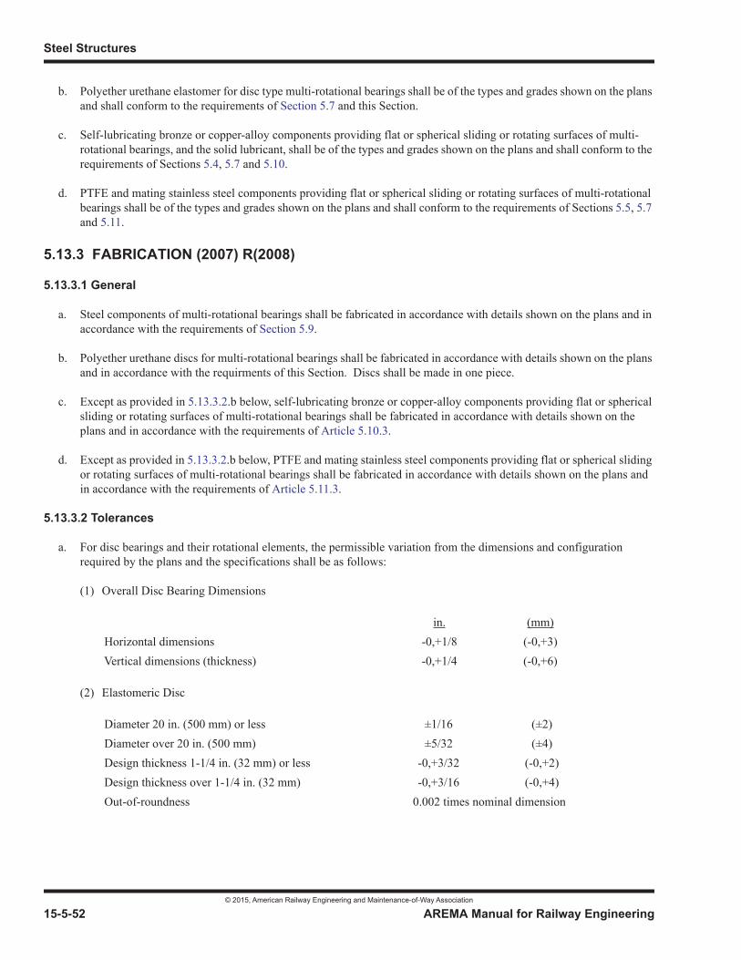
Steel Structures
© 2015, American Railway Engineering and Maintenance-of-Way Association
15-5-52 AREMA Manual for Railway Engineering
b. Polyether urethane elastomer for disc type multi-rotational bearings shall be of the types and grades shown on the plans and shall conform to the requirements of Section 5.7 and this Section.
c. Self-lubricating bronze or copper-alloy components providing flat or spherical sliding or rotating surfaces of multi-rotational bearings, and the solid lubricant, shall be of the types and grades shown on the plans and shall conform to the requirements of Sections 5.4, 5.7 and 5.10.
d. PTFE and mating stainless steel components providing flat or spherical sliding or rotating surfaces of multi-rotational bearings shall be of the types and grades shown on the plans and shall conform to the requirements of Sections 5.5, 5.7and 5.11.
5.13.3 FABRICATION (2007) R(2008)
5.13.3.1 General
a. Steel components of multi-rotational bearings shall be fabricated in accordance with details shown on the plans and in accordance with the requirements of Section 5.9.
b. Polyether urethane discs for multi-rotational bearings shall be fabricated in accordance with details shown on the plans and in accordance with the requirments of this Section. Discs shall be made in one piece.
c. Except as provided in 5.13.3.2.b below, self-lubricating bronze or copper-alloy components providing flat or spherical sliding or rotating surfaces of multi-rotational bearings shall be fabricated in accordance with details shown on the plans and in accordance with the requirements of Article 5.10.3.
d. Except as provided in 5.13.3.2.b below, PTFE and mating stainless steel components providing flat or spherical sliding or rotating surfaces of multi-rotational bearings shall be fabricated in accordance with details shown on the plans and in accordance with the requirements of Article 5.11.3.
5.13.3.2 Tolerances
a. For disc bearings and their rotational elements, the permissible variation from the dimensions and configuration required by the plans and the specifications shall be as follows:
(1) Overall Disc Bearing Dimensions
(2) Elastomeric Disc
in. (mm)Horizontal dimensions -0,+1/8 (-0,+3)Vertical dimensions (thickness) -0,+1/4 (-0,+6)
Diameter 20 in. (500 mm) or less ±1/16 (±2)Diameter over 20 in. (500 mm) ±5/32 (±4)Design thickness 1-1/4 in. (32 mm) or less -0,+3/32 (-0,+2)Design thickness over 1-1/4 in. (32 mm) -0,+3/16 (-0,+4)Out-of-roundness 0.002 times nominal dimension
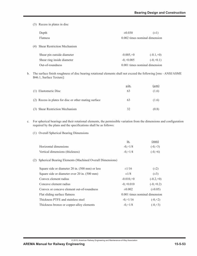
Bearing Design and Construction
© 2015, American Railway Engineering and Maintenance-of-Way Association
AREMA Manual for Railway Engineering 15-5-53
1
3
4
(3) Recess in plates in disc
(4) Shear Restriction Mechanism
b. The surface finish roughness of disc bearing rotational elements shall not exceed the following [rms - ANSI/ASME B46.1, Surface Texture]:
c. For spherical bearings and their rotational elements, the permissible variation from the dimensions and configuration required by the plans and the specifications shall be as follows:
(1) Overall Spherical Bearing Dimensions
(2) Spherical Bearing Elements (Machined Overall Dimensions)
Depth ±0.030 (±1)Flatness 0.002 times nominal dimension
Shear pin outside diameter -0.005,+0 (-0.1,+0)Shear ring inside diameter -0,+0.005 (-0,+0.1)Out-of-roundness 0.001 times nominal dimension
in. m)(1) Elastomeric Disc 63 (1.6)
(2) Recess in plates for disc or other mating surface 63 (1.6)
(3) Shear Restriction Mechanism 32 (0.8)
in. (mm)Horizontal dimensions -0,+1/8 (-0,+3)Vertical dimensions (thickness) -0,+1/4 (-0,+6)
Square side or diameter 20 in. (500 mm) or less ±1/16 (±2)Square side or diameter over 20 in. (500 mm) ±1/8 (±3)Convex element radius -0.010,+0 (-0.2,+0)Concave element radius -0,+0.010 (-0,+0.2)Convex or concave element out-of-roundness ±0.002 (±0.05)Flat sliding surface flatness 0.001 times nominal dimensionThickness PTFE and stainless steel -0,+1/16 (-0,+2)Thickness bronze or copper-alloy elements -0,+1/8 (-0,+3)
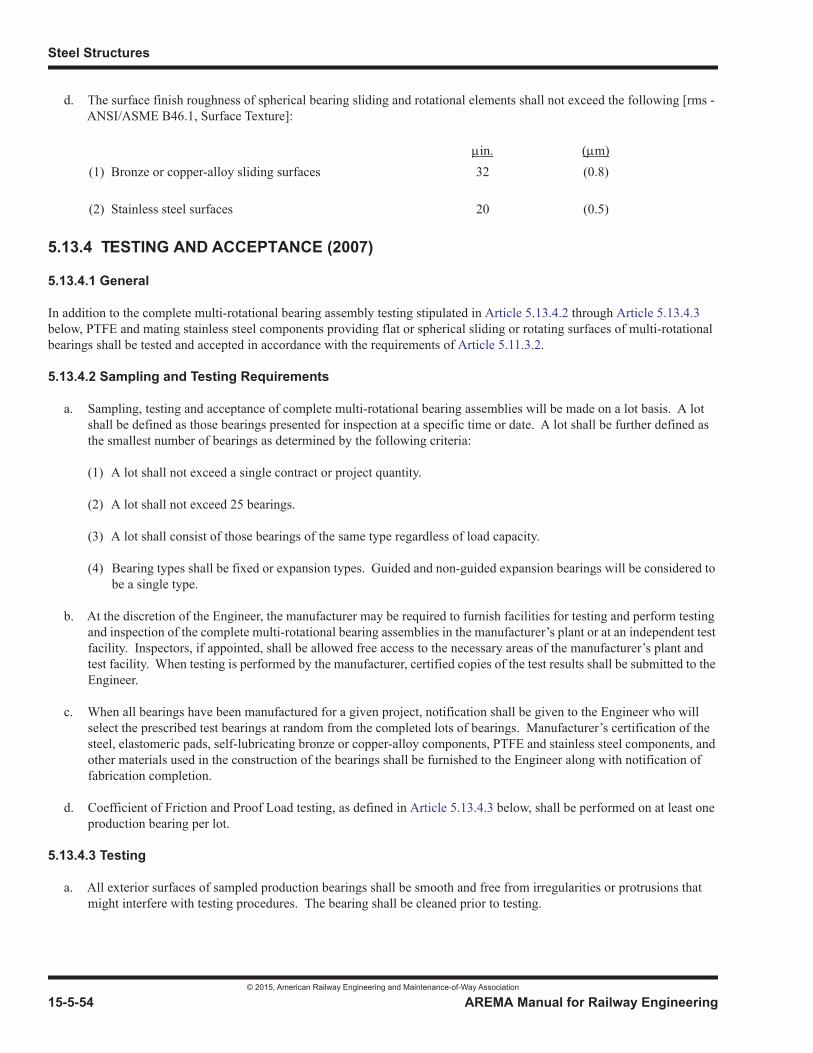
Steel Structures
© 2015, American Railway Engineering and Maintenance-of-Way Association
15-5-54 AREMA Manual for Railway Engineering
d. The surface finish roughness of spherical bearing sliding and rotational elements shall not exceed the following [rms - ANSI/ASME B46.1, Surface Texture]:
5.13.4 TESTING AND ACCEPTANCE (2007)
5.13.4.1 General
In addition to the complete multi-rotational bearing assembly testing stipulated in Article 5.13.4.2 through Article 5.13.4.3below, PTFE and mating stainless steel components providing flat or spherical sliding or rotating surfaces of multi-rotational bearings shall be tested and accepted in accordance with the requirements of Article 5.11.3.2.
5.13.4.2 Sampling and Testing Requirements
a. Sampling, testing and acceptance of complete multi-rotational bearing assemblies will be made on a lot basis. A lot shall be defined as those bearings presented for inspection at a specific time or date. A lot shall be further defined as the smallest number of bearings as determined by the following criteria:
(1) A lot shall not exceed a single contract or project quantity.
(2) A lot shall not exceed 25 bearings.
(3) A lot shall consist of those bearings of the same type regardless of load capacity.
(4) Bearing types shall be fixed or expansion types. Guided and non-guided expansion bearings will be considered to be a single type.
b. At the discretion of the Engineer, the manufacturer may be required to furnish facilities for testing and perform testing and inspection of the complete multi-rotational bearing assemblies in the manufacturer’s plant or at an independent test facility. Inspectors, if appointed, shall be allowed free access to the necessary areas of the manufacturer’s plant and test facility. When testing is performed by the manufacturer, certified copies of the test results shall be submitted to the Engineer.
c. When all bearings have been manufactured for a given project, notification shall be given to the Engineer who will select the prescribed test bearings at random from the completed lots of bearings. Manufacturer’s certification of the steel, elastomeric pads, self-lubricating bronze or copper-alloy components, PTFE and stainless steel components, and other materials used in the construction of the bearings shall be furnished to the Engineer along with notification of fabrication completion.
d. Coefficient of Friction and Proof Load testing, as defined in Article 5.13.4.3 below, shall be performed on at least one production bearing per lot.
5.13.4.3 Testing
a. All exterior surfaces of sampled production bearings shall be smooth and free from irregularities or protrusions that might interfere with testing procedures. The bearing shall be cleaned prior to testing.
in. m)(1) Bronze or copper-alloy sliding surfaces 32 (0.8)
(2) Stainless steel surfaces 20 (0.5)
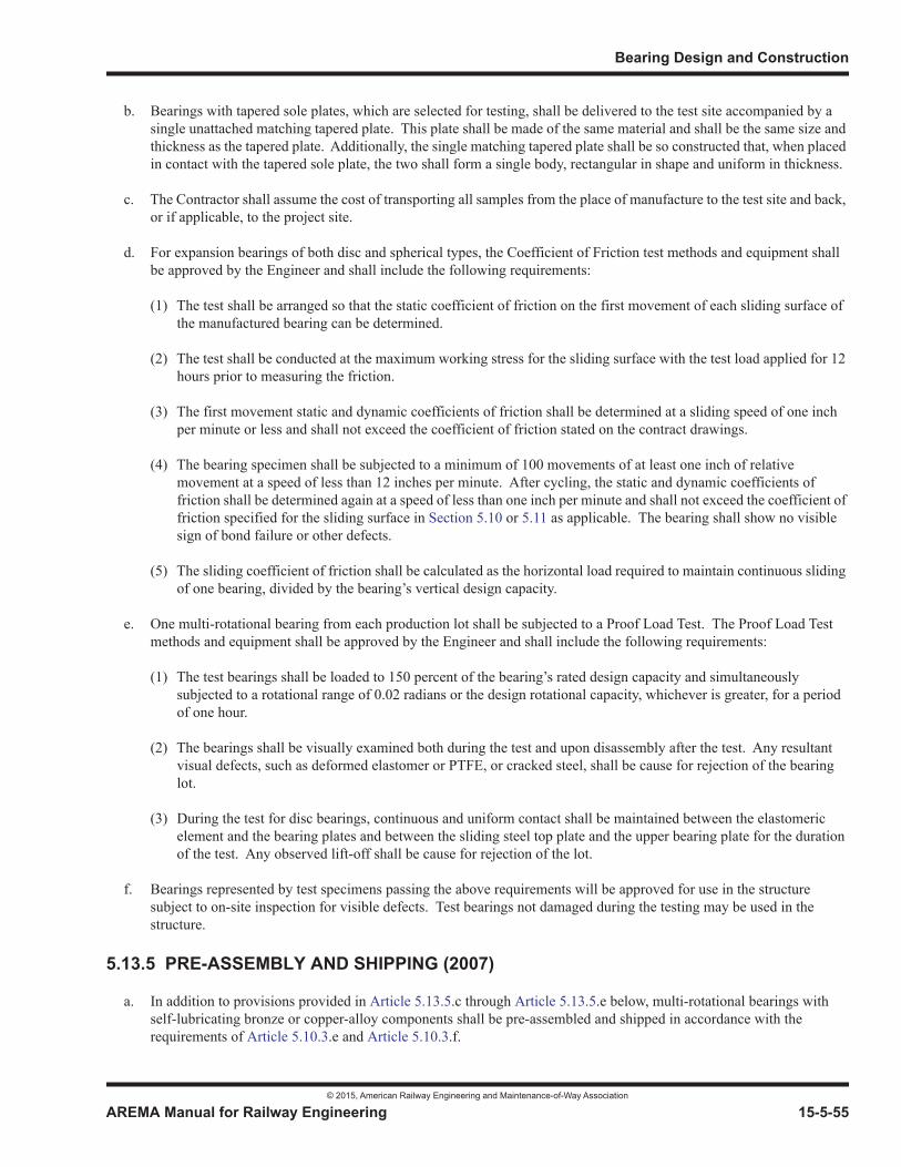
Bearing Design and Construction
© 2015, American Railway Engineering and Maintenance-of-Way Association
AREMA Manual for Railway Engineering 15-5-55
1
3
4
b. Bearings with tapered sole plates, which are selected for testing, shall be delivered to the test site accompanied by a single unattached matching tapered plate. This plate shall be made of the same material and shall be the same size and thickness as the tapered plate. Additionally, the single matching tapered plate shall be so constructed that, when placed in contact with the tapered sole plate, the two shall form a single body, rectangular in shape and uniform in thickness.
c. The Contractor shall assume the cost of transporting all samples from the place of manufacture to the test site and back, or if applicable, to the project site.
d. For expansion bearings of both disc and spherical types, the Coefficient of Friction test methods and equipment shall be approved by the Engineer and shall include the following requirements:
(1) The test shall be arranged so that the static coefficient of friction on the first movement of each sliding surface of the manufactured bearing can be determined.
(2) The test shall be conducted at the maximum working stress for the sliding surface with the test load applied for 12 hours prior to measuring the friction.
(3) The first movement static and dynamic coefficients of friction shall be determined at a sliding speed of one inch per minute or less and shall not exceed the coefficient of friction stated on the contract drawings.
(4) The bearing specimen shall be subjected to a minimum of 100 movements of at least one inch of relative movement at a speed of less than 12 inches per minute. After cycling, the static and dynamic coefficients of friction shall be determined again at a speed of less than one inch per minute and shall not exceed the coefficient of friction specified for the sliding surface in Section 5.10 or 5.11 as applicable. The bearing shall show no visible sign of bond failure or other defects.
(5) The sliding coefficient of friction shall be calculated as the horizontal load required to maintain continuous sliding of one bearing, divided by the bearing’s vertical design capacity.
e. One multi-rotational bearing from each production lot shall be subjected to a Proof Load Test. The Proof Load Test methods and equipment shall be approved by the Engineer and shall include the following requirements:
(1) The test bearings shall be loaded to 150 percent of the bearing’s rated design capacity and simultaneously subjected to a rotational range of 0.02 radians or the design rotational capacity, whichever is greater, for a period of one hour.
(2) The bearings shall be visually examined both during the test and upon disassembly after the test. Any resultant visual defects, such as deformed elastomer or PTFE, or cracked steel, shall be cause for rejection of the bearing lot.
(3) During the test for disc bearings, continuous and uniform contact shall be maintained between the elastomeric element and the bearing plates and between the sliding steel top plate and the upper bearing plate for the duration of the test. Any observed lift-off shall be cause for rejection of the lot.
f. Bearings represented by test specimens passing the above requirements will be approved for use in the structure subject to on-site inspection for visible defects. Test bearings not damaged during the testing may be used in the structure.
5.13.5 PRE-ASSEMBLY AND SHIPPING (2007)
a. In addition to provisions provided in Article 5.13.5.c through Article 5.13.5.e below, multi-rotational bearings with self-lubricating bronze or copper-alloy components shall be pre-assembled and shipped in accordance with the requirements of Article 5.10.3.e and Article 5.10.3.f.
Steel Structures
© 2015, American Railway Engineering and Maintenance-of-Way Association
15-5-56 AREMA Manual for Railway Engineering
b. In addition to provisions provided in Article 5.13.5.c through Article 5.13.5.e below, multi-rotational bearings with PTFE elements shall be pre-assembled and shipped in accordance with the requirements of Article 5.11.3.3.
c. Multi-rotational bearings shall be securely pre-assembled as units by the bearing supplier so that they may be shipped to the jobsite and stored without relative movement of the bearing components. Bearings shall be wrapped in moisture resistant and dust resistant material to protect against shipping and jobsite conditions.
d. Care shall be taken to ensure that bearings at the jobsite are stored in a dry sheltered area free from dirt or dust until installation.
e. When bearings are to be inspected on site they shall be inspected within one week of arrival and may not be disassembled except with approval of the Engineer and under the supervision of the manufacturer or his representative. Following inspection, the wrapping shall be reapplied and the bearings kept clean until installation.
5.13.6 ERECTION (2007)
a. In addition to provisions in Article 5.13.6.d through Article 5.13.6.i below, multi-rotational bearings with self-lubricating bronze or copper-alloy components shall be erected in accordance with the requirements of Article 5.10.4.
b. In addition to provisions in Article 5.13.6.d through Article 5.13.6.i below, multi-rotational bearings with PTFE elements shall be erected in accordance with the requirements of Article 5.11.4.
c. In addition to provisions provided in Article 5.13.6.d through Article 5.13.6.i below, multi-rotational bearings with polyether urethane elastomeric disc elements shall be erected in accordance with the requirements of Article 5.12.12.
d. Multi-rotational bearings shall be evenly supported over their upper and lower surfaces under all erection and service conditions.
e. Multi-rotational bearings shall be lifted by their undersides only, or by specially designed lifting lugs.
f. When installing multi-rotational bearings, care shall be taken to avoid damage to, and contamination of, bearing surfaces.
g. Align the centerlines of the bearing assembly with those of the substructure as shown on the plans. On guided bearings, special care shall be taken to properly align the guiding mechanism with the expansion direction of the structure.
h. Bearing straps or retaining clamps shall be left in place as long as possible to ensure that parts of the bearings are not inadvertently displaced relative to each other. Care must be taken to remove straps or clamps before any normal structural movement takes place, such as post-tensioning, etc.
i. Set offsets of upper and lower bearing parts as required by contract drawings.
© 2015, American Railway Engineering and Maintenance-of-Way Association 15-6-1
1
3
15Part 6
Movable Bridges1
— 2015 —
FOREWORD
The purpose of this part is to supplement or modify preceding parts of this manual in order to formulate specific and detailed rules as a guide for the design, fabrication and erection of movable railway bridges. Part 1, Design, Part 3, Fabrication and Part4, Erection are applicable to movable railway bridges except as modified by this part. References used in this part are found at the end of this chapter. See Reference 33, 66, 70, 71, 74, 76, 77, 88, 89, 131, 153, 154, and 158.
TABLE OF CONTENTS
Section/Article Description Page
6.1 Proposals and General Requirements . . . . . . . . . . . . . . . . . . . . . . . . . . . . . . . . . . . . . . . . . . . . . . . . . . . . . . 15-6-56.1.1 General (1986) R(2010) . . . . . . . . . . . . . . . . . . . . . . . . . . . . . . . . . . . . . . . . . . . . . . . . . . . . . . . . . . . . 15-6-56.1.2 Abbreviations (2014) . . . . . . . . . . . . . . . . . . . . . . . . . . . . . . . . . . . . . . . . . . . . . . . . . . . . . . . . . . . . . . 15-6-56.1.3 Time of Opening (1986) R(2010) . . . . . . . . . . . . . . . . . . . . . . . . . . . . . . . . . . . . . . . . . . . . . . . . . . . . 15-6-66.1.4 Machinery and Hydraulic Drawings (1996) R(2010) . . . . . . . . . . . . . . . . . . . . . . . . . . . . . . . . . . . . . 15-6-66.1.5 Machinery and Hydraulic Design (1997) R(2010) . . . . . . . . . . . . . . . . . . . . . . . . . . . . . . . . . . . . . . . 15-6-66.1.6 Weight and Center of Gravity (1986) R(2010) . . . . . . . . . . . . . . . . . . . . . . . . . . . . . . . . . . . . . . . . . . 15-6-76.1.7 Houses (1986) R(2010) . . . . . . . . . . . . . . . . . . . . . . . . . . . . . . . . . . . . . . . . . . . . . . . . . . . . . . . . . . . . 15-6-76.1.8 Signals and Interlocking (2003) R(2013). . . . . . . . . . . . . . . . . . . . . . . . . . . . . . . . . . . . . . . . . . . . . . . 15-6-76.1.9 Warning Lights (1986) R(2010). . . . . . . . . . . . . . . . . . . . . . . . . . . . . . . . . . . . . . . . . . . . . . . . . . . . . . 15-6-76.1.10 Communication (1997) R(2010) . . . . . . . . . . . . . . . . . . . . . . . . . . . . . . . . . . . . . . . . . . . . . . . . . . . . . 15-6-76.1.11 Wrenches (1986) R(2010) . . . . . . . . . . . . . . . . . . . . . . . . . . . . . . . . . . . . . . . . . . . . . . . . . . . . . . . . . . 15-6-86.1.12 Wiring Diagrams, Operator’s Instructions, Electrical, Hydraulic and Mechanical Data Manuals, and
Lubrication Charts (2010) . . . . . . . . . . . . . . . . . . . . . . . . . . . . . . . . . . . . . . . . . . . . . . . . . . . . . . . . . . 15-6-86.1.13 Classification of Bridge Work (2003) R(2010) . . . . . . . . . . . . . . . . . . . . . . . . . . . . . . . . . . . . . . . . . . 15-6-86.1.14 Parts Included in Classes (2008) . . . . . . . . . . . . . . . . . . . . . . . . . . . . . . . . . . . . . . . . . . . . . . . . . . . . . 15-6-96.1.15 Optional Requirements (1986) R(2010) . . . . . . . . . . . . . . . . . . . . . . . . . . . . . . . . . . . . . . . . . . . . . . . 15-6-12
1 References, Vol. 23, 1922, pp. 169, 1051; Vol. 36, 1935, pp. 632, 986; Vol. 51, 1950, pp. 445, 606; Vol. 52, 1951, pp. 447, 869; Vol. 53, 1952, pp. 522, 1064; Vol. 54, 1953, pp. 906, 1346; Vol. 57, 1956, pp. 555, 998; Vol. 62, 1961, pp. 548, 876; Vol. 63, 1962, pp. 383, 699; Vol. 65, 1964, pp. 383, 775; Vol. 66, 1965, pp. 292, 653; Vol. 67, 1966, pp. 342, 697; Vol. 70, 1969, p. 241; Vol. 75, 1974, p. 257; Vol. 78, 1977, p. 75; Vol. 79, 1978, p. 45; Vol. 81, 1980, p. 130; Vol. 84, 1983, p. 100; Vol. 86, 1985, p. 90; Vol. 87, 1986, p. 105; Vol. 88. 1987, p. 89; Vol. 92, 1991, p. 79; Vol. 93, 1992, p. 124; Vol. 94, p. 1; Vol. 97, p. 172. Reapproved with revisions 1996.See Part 9 Commentary
Steel Structures
© 2015, American Railway Engineering and Maintenance-of-Way Association
15-6-2 AREMA Manual for Railway Engineering
TABLE OF CONTENTS (CONT)
Section/Article Description Page
6.1.16 Guarantees (2003) R(2015) . . . . . . . . . . . . . . . . . . . . . . . . . . . . . . . . . . . . . . . . . . . . . . . . . . . . . . . . 15-6-12
6.2 General Features of Design . . . . . . . . . . . . . . . . . . . . . . . . . . . . . . . . . . . . . . . . . . . . . . . . . . . . . . . . . . . . . . 15-6-136.2.1 Material (1997) R(2013). . . . . . . . . . . . . . . . . . . . . . . . . . . . . . . . . . . . . . . . . . . . . . . . . . . . . . . . . . . 15-6-136.2.2 Types of Bridges (1997) R(2013). . . . . . . . . . . . . . . . . . . . . . . . . . . . . . . . . . . . . . . . . . . . . . . . . . . . 15-6-136.2.3 Counterweights (1997) R(2003). . . . . . . . . . . . . . . . . . . . . . . . . . . . . . . . . . . . . . . . . . . . . . . . . . . . . 15-6-146.2.4 Aligning and Locking (1986) R(2004) . . . . . . . . . . . . . . . . . . . . . . . . . . . . . . . . . . . . . . . . . . . . . . . . 15-6-146.2.5 Emergency Operation (1986) R(2002) . . . . . . . . . . . . . . . . . . . . . . . . . . . . . . . . . . . . . . . . . . . . . . . . 15-6-146.2.6 Standby Power (1986) R(2002) . . . . . . . . . . . . . . . . . . . . . . . . . . . . . . . . . . . . . . . . . . . . . . . . . . . . . 15-6-146.2.7 Interlocking (1986) R(2002). . . . . . . . . . . . . . . . . . . . . . . . . . . . . . . . . . . . . . . . . . . . . . . . . . . . . . . . 15-6-156.2.8 Insulation of Track (1986) R(2002) . . . . . . . . . . . . . . . . . . . . . . . . . . . . . . . . . . . . . . . . . . . . . . . . . . 15-6-156.2.9 Houses for Operators, Machinery, Hydraulic Equipment, Electrical Equipment
and Signal Devices (2003) . . . . . . . . . . . . . . . . . . . . . . . . . . . . . . . . . . . . . . . . . . . . . . . . . . . . . . . . . 15-6-156.2.10 Stairways, Walks, and Elevators (2003) . . . . . . . . . . . . . . . . . . . . . . . . . . . . . . . . . . . . . . . . . . . . . . . 15-6-156.2.11 Materials for Machinery and Similar Parts (1993) R(2003) . . . . . . . . . . . . . . . . . . . . . . . . . . . . . . . 15-6-166.2.12 Rail Ends (2015). . . . . . . . . . . . . . . . . . . . . . . . . . . . . . . . . . . . . . . . . . . . . . . . . . . . . . . . . . . . . . . . . 15-6-17
6.3 Loads, Forces and Stresses. . . . . . . . . . . . . . . . . . . . . . . . . . . . . . . . . . . . . . . . . . . . . . . . . . . . . . . . . . . . . . . 15-6-176.3.1 Live Load (1993) R(2010) . . . . . . . . . . . . . . . . . . . . . . . . . . . . . . . . . . . . . . . . . . . . . . . . . . . . . . . . . 15-6-176.3.2 Impact Load (2015) . . . . . . . . . . . . . . . . . . . . . . . . . . . . . . . . . . . . . . . . . . . . . . . . . . . . . . . . . . . . . . 15-6-176.3.3 End Ties (2013) . . . . . . . . . . . . . . . . . . . . . . . . . . . . . . . . . . . . . . . . . . . . . . . . . . . . . . . . . . . . . . . . . 15-6-186.3.4 Fatigue (1983) R(2010) . . . . . . . . . . . . . . . . . . . . . . . . . . . . . . . . . . . . . . . . . . . . . . . . . . . . . . . . . . . 15-6-186.3.5 Wind Forces and Ice Load (2011) . . . . . . . . . . . . . . . . . . . . . . . . . . . . . . . . . . . . . . . . . . . . . . . . . . . 15-6-186.3.6 Power Requirements and Machinery Design (2003) . . . . . . . . . . . . . . . . . . . . . . . . . . . . . . . . . . . . . 15-6-196.3.7 Machinery Resistances (1983) R(2010) . . . . . . . . . . . . . . . . . . . . . . . . . . . . . . . . . . . . . . . . . . . . . . . 15-6-196.3.8 Machinery Losses (1983) R(2010). . . . . . . . . . . . . . . . . . . . . . . . . . . . . . . . . . . . . . . . . . . . . . . . . . . 15-6-206.3.9 Brakes, and Machinery Design for Braking Forces (2012) . . . . . . . . . . . . . . . . . . . . . . . . . . . . . . . . 15-6-216.3.10 Machinery Design (1983). . . . . . . . . . . . . . . . . . . . . . . . . . . . . . . . . . . . . . . . . . . . . . . . . . . . . . . . . . 15-6-226.3.11 Machinery Supports (2013) . . . . . . . . . . . . . . . . . . . . . . . . . . . . . . . . . . . . . . . . . . . . . . . . . . . . . . . . 15-6-226.3.12 Anchorage (1983) R(2010). . . . . . . . . . . . . . . . . . . . . . . . . . . . . . . . . . . . . . . . . . . . . . . . . . . . . . . . . 15-6-226.3.13 Special Provisions for Swing Bridges (1983) R(2002) . . . . . . . . . . . . . . . . . . . . . . . . . . . . . . . . . . . 15-6-236.3.14 Special Provisions for Bascule Bridges (1984) R(2010) . . . . . . . . . . . . . . . . . . . . . . . . . . . . . . . . . . 15-6-246.3.15 Special Provisions for Vertical Lift Bridges (2004) R(2010) . . . . . . . . . . . . . . . . . . . . . . . . . . . . . . . 15-6-25
6.4 Basic Allowable Stresses and Hydraulic Pressures . . . . . . . . . . . . . . . . . . . . . . . . . . . . . . . . . . . . . . . . . . . 15-6-276.4.1 Structural Parts (1993) R(2010) . . . . . . . . . . . . . . . . . . . . . . . . . . . . . . . . . . . . . . . . . . . . . . . . . . . . . 15-6-276.4.2 Machinery Parts (2013) . . . . . . . . . . . . . . . . . . . . . . . . . . . . . . . . . . . . . . . . . . . . . . . . . . . . . . . . . . . 15-6-276.4.3 Bearing (1997) R(2010) . . . . . . . . . . . . . . . . . . . . . . . . . . . . . . . . . . . . . . . . . . . . . . . . . . . . . . . . . . . 15-6-296.4.4 Heating and Seizing (1992) R(2010) . . . . . . . . . . . . . . . . . . . . . . . . . . . . . . . . . . . . . . . . . . . . . . . . . 15-6-296.4.5 Line Bearing Load (1984) R(2013) . . . . . . . . . . . . . . . . . . . . . . . . . . . . . . . . . . . . . . . . . . . . . . . . . . 15-6-306.4.6 Shafts (1984) R(2010) . . . . . . . . . . . . . . . . . . . . . . . . . . . . . . . . . . . . . . . . . . . . . . . . . . . . . . . . . . . . 15-6-316.4.7 Bolts in Tension (1984) R(2003) . . . . . . . . . . . . . . . . . . . . . . . . . . . . . . . . . . . . . . . . . . . . . . . . . . . . 15-6-316.4.8 Hydraulic Systems and Components (1984) R(2010) . . . . . . . . . . . . . . . . . . . . . . . . . . . . . . . . . . . . 15-6-32
6.5 General Details . . . . . . . . . . . . . . . . . . . . . . . . . . . . . . . . . . . . . . . . . . . . . . . . . . . . . . . . . . . . . . . . . . . . . . . . 15-6-336.5.1 Fits and Surface Finishes (1984) R(2013) . . . . . . . . . . . . . . . . . . . . . . . . . . . . . . . . . . . . . . . . . . . . . 15-6-336.5.2 Rail End Connections (1984) R(2012) . . . . . . . . . . . . . . . . . . . . . . . . . . . . . . . . . . . . . . . . . . . . . . . . 15-6-336.5.3 Air Buffers (1997) R(2012) . . . . . . . . . . . . . . . . . . . . . . . . . . . . . . . . . . . . . . . . . . . . . . . . . . . . . . . . 15-6-346.5.4 Counterweights (2003) R(2012). . . . . . . . . . . . . . . . . . . . . . . . . . . . . . . . . . . . . . . . . . . . . . . . . . . . . 15-6-34
Movable Bridges
© 2015, American Railway Engineering and Maintenance-of-Way Association
AREMA Manual for Railway Engineering 15-6-3
1
3
4
TABLE OF CONTENTS (CONT)
Section/Article Description Page
6.5.5 Concrete (1984) R(2012) . . . . . . . . . . . . . . . . . . . . . . . . . . . . . . . . . . . . . . . . . . . . . . . . . . . . . . . . . . . 15-6-346.5.6 Machinery in General (1984) R(2013). . . . . . . . . . . . . . . . . . . . . . . . . . . . . . . . . . . . . . . . . . . . . . . . . 15-6-356.5.7 Journal Bearings (1984) R(2013). . . . . . . . . . . . . . . . . . . . . . . . . . . . . . . . . . . . . . . . . . . . . . . . . . . . . 15-6-356.5.8 Linings (1984) R(2013) . . . . . . . . . . . . . . . . . . . . . . . . . . . . . . . . . . . . . . . . . . . . . . . . . . . . . . . . . . . . 15-6-356.5.9 Step Bearings (1984) R(2013) . . . . . . . . . . . . . . . . . . . . . . . . . . . . . . . . . . . . . . . . . . . . . . . . . . . . . . . 15-6-366.5.10 Roller Bearings for Heavy Loads (2003) . . . . . . . . . . . . . . . . . . . . . . . . . . . . . . . . . . . . . . . . . . . . . . . 15-6-366.5.11 Roller and Ball Bearings (1997) R(2003) . . . . . . . . . . . . . . . . . . . . . . . . . . . . . . . . . . . . . . . . . . . . . . 15-6-366.5.12 Speed Reducers (2010) . . . . . . . . . . . . . . . . . . . . . . . . . . . . . . . . . . . . . . . . . . . . . . . . . . . . . . . . . . . . 15-6-366.5.13 Lubrication (2008) . . . . . . . . . . . . . . . . . . . . . . . . . . . . . . . . . . . . . . . . . . . . . . . . . . . . . . . . . . . . . . . . 15-6-376.5.14 Shafts (1983) R(2003) . . . . . . . . . . . . . . . . . . . . . . . . . . . . . . . . . . . . . . . . . . . . . . . . . . . . . . . . . . . . . 15-6-386.5.15 Shaft Couplings (1983) R(2013) . . . . . . . . . . . . . . . . . . . . . . . . . . . . . . . . . . . . . . . . . . . . . . . . . . . . . 15-6-396.5.16 Longitudinal Thrust (1983) R(2003) . . . . . . . . . . . . . . . . . . . . . . . . . . . . . . . . . . . . . . . . . . . . . . . . . . 15-6-396.5.17 Collars (1997) R(2003) . . . . . . . . . . . . . . . . . . . . . . . . . . . . . . . . . . . . . . . . . . . . . . . . . . . . . . . . . . . . 15-6-396.5.18 Gear Teeth (1983) R(2003) . . . . . . . . . . . . . . . . . . . . . . . . . . . . . . . . . . . . . . . . . . . . . . . . . . . . . . . . . 15-6-396.5.19 Strength of Gear Teeth (1983) R(2003). . . . . . . . . . . . . . . . . . . . . . . . . . . . . . . . . . . . . . . . . . . . . . . . 15-6-406.5.20 Worm Gearing (2003) . . . . . . . . . . . . . . . . . . . . . . . . . . . . . . . . . . . . . . . . . . . . . . . . . . . . . . . . . . . . . 15-6-426.5.21 Screw Gearing and Cams (1983) R(2013) . . . . . . . . . . . . . . . . . . . . . . . . . . . . . . . . . . . . . . . . . . . . . . 15-6-426.5.22 Hubs (1983) R(2010) . . . . . . . . . . . . . . . . . . . . . . . . . . . . . . . . . . . . . . . . . . . . . . . . . . . . . . . . . . . . . . 15-6-426.5.23 Keys and Keyways for Machinery Parts (2003) R(2010) . . . . . . . . . . . . . . . . . . . . . . . . . . . . . . . . . . 15-6-426.5.24 Keys for Trunnions (1983) R(2010) . . . . . . . . . . . . . . . . . . . . . . . . . . . . . . . . . . . . . . . . . . . . . . . . . . 15-6-436.5.25 Bolts and Nuts (2003) R(2014) . . . . . . . . . . . . . . . . . . . . . . . . . . . . . . . . . . . . . . . . . . . . . . . . . . . . . . 15-6-436.5.26 Set Screws (1997) R(2010) . . . . . . . . . . . . . . . . . . . . . . . . . . . . . . . . . . . . . . . . . . . . . . . . . . . . . . . . . 15-6-446.5.27 Tapped Holes (1983) R(2010) . . . . . . . . . . . . . . . . . . . . . . . . . . . . . . . . . . . . . . . . . . . . . . . . . . . . . . . 15-6-446.5.28 Springs (1983) R(2010) . . . . . . . . . . . . . . . . . . . . . . . . . . . . . . . . . . . . . . . . . . . . . . . . . . . . . . . . . . . . 15-6-446.5.29 Equalizers (1983) R(2002). . . . . . . . . . . . . . . . . . . . . . . . . . . . . . . . . . . . . . . . . . . . . . . . . . . . . . . . . . 15-6-456.5.30 Covers (2003). . . . . . . . . . . . . . . . . . . . . . . . . . . . . . . . . . . . . . . . . . . . . . . . . . . . . . . . . . . . . . . . . . . . 15-6-456.5.31 Safety Devices (1983) R(2002) . . . . . . . . . . . . . . . . . . . . . . . . . . . . . . . . . . . . . . . . . . . . . . . . . . . . . . 15-6-456.5.32 Drain Holes (1983) R(2002) . . . . . . . . . . . . . . . . . . . . . . . . . . . . . . . . . . . . . . . . . . . . . . . . . . . . . . . . 15-6-456.5.33 Compressed Air Devices (2003) . . . . . . . . . . . . . . . . . . . . . . . . . . . . . . . . . . . . . . . . . . . . . . . . . . . . . 15-6-456.5.34 Special Provisions for Swing Bridges (2003) . . . . . . . . . . . . . . . . . . . . . . . . . . . . . . . . . . . . . . . . . . . 15-6-456.5.35 Special Provisions for Bascule Bridges (2013) . . . . . . . . . . . . . . . . . . . . . . . . . . . . . . . . . . . . . . . . . . 15-6-476.5.36 Special Provisions for Vertical Lift Bridges (1997) R(2014). . . . . . . . . . . . . . . . . . . . . . . . . . . . . . . . 15-6-496.5.37 Hydraulic Systems . . . . . . . . . . . . . . . . . . . . . . . . . . . . . . . . . . . . . . . . . . . . . . . . . . . . . . . . . . . . . . . . 15-6-52
6.6 Wire Ropes and Sockets. . . . . . . . . . . . . . . . . . . . . . . . . . . . . . . . . . . . . . . . . . . . . . . . . . . . . . . . . . . . . . . . . . 15-6-686.6.1 Manufacturer (1984) R(2010) . . . . . . . . . . . . . . . . . . . . . . . . . . . . . . . . . . . . . . . . . . . . . . . . . . . . . . . 15-6-686.6.2 Diameter of Rope (2010) . . . . . . . . . . . . . . . . . . . . . . . . . . . . . . . . . . . . . . . . . . . . . . . . . . . . . . . . . . . 15-6-686.6.3 Construction (2010) . . . . . . . . . . . . . . . . . . . . . . . . . . . . . . . . . . . . . . . . . . . . . . . . . . . . . . . . . . . . . . . 15-6-686.6.4 Lay (2010) . . . . . . . . . . . . . . . . . . . . . . . . . . . . . . . . . . . . . . . . . . . . . . . . . . . . . . . . . . . . . . . . . . . . . . 15-6-696.6.5 Lubrication During Fabrication (1983) R(2010) . . . . . . . . . . . . . . . . . . . . . . . . . . . . . . . . . . . . . . . . . 15-6-696.6.6 Splices (1983) R(2010) . . . . . . . . . . . . . . . . . . . . . . . . . . . . . . . . . . . . . . . . . . . . . . . . . . . . . . . . . . . . 15-6-696.6.7 Wire – Physical Properties (2010) . . . . . . . . . . . . . . . . . . . . . . . . . . . . . . . . . . . . . . . . . . . . . . . . . . . . 15-6-696.6.8 Ultimate Strength (2010) . . . . . . . . . . . . . . . . . . . . . . . . . . . . . . . . . . . . . . . . . . . . . . . . . . . . . . . . . . . 15-6-706.6.9 Rejection (1985) R(2010) . . . . . . . . . . . . . . . . . . . . . . . . . . . . . . . . . . . . . . . . . . . . . . . . . . . . . . . . . . 15-6-706.6.10 Prestretching (1985) R(2010). . . . . . . . . . . . . . . . . . . . . . . . . . . . . . . . . . . . . . . . . . . . . . . . . . . . . . . . 15-6-706.6.11 Sockets (1985) R(2010) . . . . . . . . . . . . . . . . . . . . . . . . . . . . . . . . . . . . . . . . . . . . . . . . . . . . . . . . . . . . 15-6-706.6.12 Facilities for Testing (1985) R(2010) . . . . . . . . . . . . . . . . . . . . . . . . . . . . . . . . . . . . . . . . . . . . . . . . . 15-6-716.6.13 Rope Length (1985) R(2010) . . . . . . . . . . . . . . . . . . . . . . . . . . . . . . . . . . . . . . . . . . . . . . . . . . . . . . . . 15-6-716.6.14 Operating Ropes (1985) R(2010). . . . . . . . . . . . . . . . . . . . . . . . . . . . . . . . . . . . . . . . . . . . . . . . . . . . . 15-6-71

Steel Structures
© 2015, American Railway Engineering and Maintenance-of-Way Association
15-6-4 AREMA Manual for Railway Engineering
TABLE OF CONTENTS (CONT)
Section/Article Description Page
6.6.15 Shipping (1985) R(2010) . . . . . . . . . . . . . . . . . . . . . . . . . . . . . . . . . . . . . . . . . . . . . . . . . . . . . . . . . . 15-6-71
6.7 Power Equipment . . . . . . . . . . . . . . . . . . . . . . . . . . . . . . . . . . . . . . . . . . . . . . . . . . . . . . . . . . . . . . . . . . . . . . 15-6-726.7.1 Power Operation (1984) R(2002). . . . . . . . . . . . . . . . . . . . . . . . . . . . . . . . . . . . . . . . . . . . . . . . . . . . 15-6-726.7.2 Manpower Operation (1984) R(2002) . . . . . . . . . . . . . . . . . . . . . . . . . . . . . . . . . . . . . . . . . . . . . . . . 15-6-726.7.3 Machines (1984) R(2003). . . . . . . . . . . . . . . . . . . . . . . . . . . . . . . . . . . . . . . . . . . . . . . . . . . . . . . . . . 15-6-726.7.4 Internal Combustion (1997) R(2002) . . . . . . . . . . . . . . . . . . . . . . . . . . . . . . . . . . . . . . . . . . . . . . . . . 15-6-726.7.5 Electric (1997) R(2003) . . . . . . . . . . . . . . . . . . . . . . . . . . . . . . . . . . . . . . . . . . . . . . . . . . . . . . . . . . . 15-6-736.7.6 Brakes for Span Operation (1983) R(2002) . . . . . . . . . . . . . . . . . . . . . . . . . . . . . . . . . . . . . . . . . . . . 15-6-936.7.7 Air Brakes (1997) R(2002). . . . . . . . . . . . . . . . . . . . . . . . . . . . . . . . . . . . . . . . . . . . . . . . . . . . . . . . . 15-6-936.7.8 Hand Brakes and Foot Brakes (1983) R(2002) . . . . . . . . . . . . . . . . . . . . . . . . . . . . . . . . . . . . . . . . . 15-6-946.7.9 Audible Navigation Signals (1983) R(2002) . . . . . . . . . . . . . . . . . . . . . . . . . . . . . . . . . . . . . . . . . . . 15-6-94
6.8 Workmanship . . . . . . . . . . . . . . . . . . . . . . . . . . . . . . . . . . . . . . . . . . . . . . . . . . . . . . . . . . . . . . . . . . . . . . . . . 15-6-946.8.1 Machinery Manufacture in General (1983) R(2010) . . . . . . . . . . . . . . . . . . . . . . . . . . . . . . . . . . . . . 15-6-946.8.2 Racks (1983) R(2010) . . . . . . . . . . . . . . . . . . . . . . . . . . . . . . . . . . . . . . . . . . . . . . . . . . . . . . . . . . . . 15-6-956.8.3 Shafts (1983) R(2010) . . . . . . . . . . . . . . . . . . . . . . . . . . . . . . . . . . . . . . . . . . . . . . . . . . . . . . . . . . . . 15-6-956.8.4 Journals (1983) R(2010). . . . . . . . . . . . . . . . . . . . . . . . . . . . . . . . . . . . . . . . . . . . . . . . . . . . . . . . . . . 15-6-956.8.5 Linings (1983) R(2010) . . . . . . . . . . . . . . . . . . . . . . . . . . . . . . . . . . . . . . . . . . . . . . . . . . . . . . . . . . . 15-6-956.8.6 Bearings (1983) R(2010) . . . . . . . . . . . . . . . . . . . . . . . . . . . . . . . . . . . . . . . . . . . . . . . . . . . . . . . . . . 15-6-966.8.7 Couplings (1983) R(2010) . . . . . . . . . . . . . . . . . . . . . . . . . . . . . . . . . . . . . . . . . . . . . . . . . . . . . . . . . 15-6-966.8.8 Hubs (1983) R(2010) . . . . . . . . . . . . . . . . . . . . . . . . . . . . . . . . . . . . . . . . . . . . . . . . . . . . . . . . . . . . . 15-6-966.8.9 Gears and Pinions (1983) R(2010) . . . . . . . . . . . . . . . . . . . . . . . . . . . . . . . . . . . . . . . . . . . . . . . . . . . 15-6-966.8.10 Bevel Gears (1983) R(2010) . . . . . . . . . . . . . . . . . . . . . . . . . . . . . . . . . . . . . . . . . . . . . . . . . . . . . . . 15-6-966.8.11 Machine Molding (2003) R(2010) . . . . . . . . . . . . . . . . . . . . . . . . . . . . . . . . . . . . . . . . . . . . . . . . . . . 15-6-966.8.12 Worms and Worm Wheels (1983) R(2010) . . . . . . . . . . . . . . . . . . . . . . . . . . . . . . . . . . . . . . . . . . . . 15-6-966.8.13 Keys and Keyways (1983) R(2010) . . . . . . . . . . . . . . . . . . . . . . . . . . . . . . . . . . . . . . . . . . . . . . . . . . 15-6-966.8.14 Bolts and Holes (1996) R(2010). . . . . . . . . . . . . . . . . . . . . . . . . . . . . . . . . . . . . . . . . . . . . . . . . . . . . 15-6-966.8.15 Assembling Machinery in Frames (1983) R(2010) . . . . . . . . . . . . . . . . . . . . . . . . . . . . . . . . . . . . . . 15-6-966.8.16 Balancing of Gears (1983) R(2010) . . . . . . . . . . . . . . . . . . . . . . . . . . . . . . . . . . . . . . . . . . . . . . . . . . 15-6-976.8.17 Assembling Machinery on Structural Supports (2003) R(2010) . . . . . . . . . . . . . . . . . . . . . . . . . . . . 15-6-976.8.18 Grooves in Journals and Linings (1983) R(2010) . . . . . . . . . . . . . . . . . . . . . . . . . . . . . . . . . . . . . . . 15-6-976.8.19 Air Buffers (1983) R(2010) . . . . . . . . . . . . . . . . . . . . . . . . . . . . . . . . . . . . . . . . . . . . . . . . . . . . . . . . 15-6-976.8.20 Special Provisions for Swing Bridges (2003) R(2010) . . . . . . . . . . . . . . . . . . . . . . . . . . . . . . . . . . . 15-6-976.8.21 Special Provisions for Bascule Bridges (2003) R(2010) . . . . . . . . . . . . . . . . . . . . . . . . . . . . . . . . . . 15-6-986.8.22 Special Provisions for Vertical Lift Bridges (1983) R(2010) . . . . . . . . . . . . . . . . . . . . . . . . . . . . . . . 15-6-99
6.9 Erection . . . . . . . . . . . . . . . . . . . . . . . . . . . . . . . . . . . . . . . . . . . . . . . . . . . . . . . . . . . . . . . . . . . . . . . . . . . . . . 15-6-996.9.1 Erection of Machinery (1996) R(2002) . . . . . . . . . . . . . . . . . . . . . . . . . . . . . . . . . . . . . . . . . . . . . . . 15-6-996.9.2 Erection of Trunnion Bearings and Counterweight Sheave Bearings (1983) R(2010) . . . . . . . . . . . 15-6-1006.9.3 Protection of Parts (1983) R(2002) . . . . . . . . . . . . . . . . . . . . . . . . . . . . . . . . . . . . . . . . . . . . . . . . . . 15-6-1006.9.4 Lubrication (2008) R(2010) . . . . . . . . . . . . . . . . . . . . . . . . . . . . . . . . . . . . . . . . . . . . . . . . . . . . . . . . 15-6-1006.9.5 Erection of Wire Ropes (1983) R(2010) . . . . . . . . . . . . . . . . . . . . . . . . . . . . . . . . . . . . . . . . . . . . . . 15-6-1016.9.6 Painting (1983) R(2010). . . . . . . . . . . . . . . . . . . . . . . . . . . . . . . . . . . . . . . . . . . . . . . . . . . . . . . . . . . 15-6-1016.9.7 Counterweights (1983) R(2003). . . . . . . . . . . . . . . . . . . . . . . . . . . . . . . . . . . . . . . . . . . . . . . . . . . . . 15-6-1016.9.8 End Lifting Devices for Swing Spans (1983) R(2010) . . . . . . . . . . . . . . . . . . . . . . . . . . . . . . . . . . . 15-6-1016.9.9 Channel Lights (1983) R(2015) . . . . . . . . . . . . . . . . . . . . . . . . . . . . . . . . . . . . . . . . . . . . . . . . . . . . . 15-6-1026.9.10 Testing (1983) R(2010) . . . . . . . . . . . . . . . . . . . . . . . . . . . . . . . . . . . . . . . . . . . . . . . . . . . . . . . . . . . 15-6-1026.9.11 Bridge Operator (1983) R(2014) . . . . . . . . . . . . . . . . . . . . . . . . . . . . . . . . . . . . . . . . . . . . . . . . . . . . 15-6-102
Movable Bridges
© 2015, American Railway Engineering and Maintenance-of-Way Association
AREMA Manual for Railway Engineering 15-6-5
1
3
4
LIST OF TABLES
Table Description Page
15-6-1 Machinery Resistances . . . . . . . . . . . . . . . . . . . . . . . . . . . . . . . . . . . . . . . . . . . . . . . . . . . . . . . . . . . . . . . . . 15-6-2015-6-2 Allowable Machinery Stresses. . . . . . . . . . . . . . . . . . . . . . . . . . . . . . . . . . . . . . . . . . . . . . . . . . . . . . . . . . . . 15-6-2715-6-3 Trunnion Bending Stresses . . . . . . . . . . . . . . . . . . . . . . . . . . . . . . . . . . . . . . . . . . . . . . . . . . . . . . . . . . . . . . 15-6-2815-6-4 Roller Maximum Bearing Load. . . . . . . . . . . . . . . . . . . . . . . . . . . . . . . . . . . . . . . . . . . . . . . . . . . . . . . . . . . 15-6-3015-6-5 Preferred Fits and Surface Finishes . . . . . . . . . . . . . . . . . . . . . . . . . . . . . . . . . . . . . . . . . . . . . . . . . . . . . . . . 15-6-3315-6-6 Torque Ratio . . . . . . . . . . . . . . . . . . . . . . . . . . . . . . . . . . . . . . . . . . . . . . . . . . . . . . . . . . . . . . . . . . . . . . . . . 15-6-72
SECTION 6.1 PROPOSALS AND GENERAL REQUIREMENTS
6.1.1 GENERAL (1986)1 R(2010)
a. The structural, mechanical, hydraulic and electrical design will be furnished by the Company, unless it is stated in the invitation for bids that such designs, or specified portions of them, are to be furnished by the Contractor.
b. The Company will furnish, with its invitation for bids, a copy of the contract form together with site plans and a full description of the requirements for the structure. These requirements will make clear the division of responsibility between Company and Contractor for designing, furnishing and erecting or installing all components of the structure, and will specify or describe all of such components which are the responsibility of or affect the work of the Contractor.
c. The Contractor shall furnish and erect the structure ready for operation and to receive trains, except for such components as are specified to be furnished and/or installed by the Company.
d. All shop drawings, assembly drawings and other papers prepared for the purpose of meeting the governing conditions and specifications of the contract shall be subject to the approval of the Engineer.
6.1.2 ABBREVIATIONS (2014)
a. The following abbreviations are used herein:
1 See Part 9 Commentary
AAR Association of American RailroadsABMA American Bearing Manufacturers AssociationAGMA American Gear Manufacturers AssociationAISE Association of Iron and Steel EngineersAISI American Iron and Steel InstituteANSI American National Standards InstituteASME American Society of Mechanical EngineersASTM American Society for Testing and MaterialsAWG American Wire GageIEEE Institute of Electrical and Electronics EngineersIPCEA Insulated Power Cable Engineers Association
Steel Structures
© 2015, American Railway Engineering and Maintenance-of-Way Association
15-6-6 AREMA Manual for Railway Engineering
b. The National Fire Protection Association shall be referenced herein by full name only.
6.1.3 TIME OF OPENING (1986) R(2010)
The time required for opening the bridge after the ends are released will be specified on the Plans for both normal and emergency operations.
The times assumed for acceleration and deceleration will be given on the Plans with a cautionary note that shorter times, particularly during braking, may seriously overstress elements in the drive train.
6.1.4 MACHINERY AND HYDRAULIC DRAWINGS (1996) R(2010)
a. The Contractor shall make an assembly drawing and detail drawings of the machinery. These drawings shall be sufficiently complete that the machinery parts may be duplicated without reference to patterns, other drawings, or individual shop practice.
b. The Contractor shall make hydraulic control circuit and piping diagrams, hydraulic power unit layouts, and all assembly and detail drawings including the electrical schematic wiring diagrams and conduit diagrams that are needed for the complete hydraulic system. The drawings shall be so complete that the hydraulic components can be replaced without having the original stock numbers of the equipment. The drawings shall also conform to the requirements of the ANSI (NFPA/JIC) T2.24.1 Section 6.3 Standards.
c. The Contractor shall make a drawing or chart showing all bearings, electrical equipment, and other elements of the bridge which require lubrication, and designating the lubricants to be used and the frequency of lubrication. Framed, sealed copies of the lubrication drawing shall be mounted in appropriate places on the bridge.
6.1.5 MACHINERY AND HYDRAULIC DESIGN (1997) R(2010)
a. Where the machinery design is prepared by the Contractor, he shall furnish complete calculations for all parts of the machinery. The calculations shall include the operating shaft torques for all pump drive motors and drive engines, hydraulic motors and rotary actuators and rod forces for hydraulic cylinders and intensifiers along with hydraulic system pressures. Calculations shall be for the following conditions:
(1) Acceleration and for retardation.
(2) Frictional resistance.
(3) Any unbalanced condition of the bridge.
(4) Wind loads.
(5) The greatest resultant combinations of resistances acting at one time under the various design conditions herein specified. The torque for starting friction shall not be combined with the torque for acceleration.
ISO International Organization for StandardizationNEC National Electrical CodeNEMA National Electrical Manufacturers AssociationNFPA National Fluid Power AssociationSAE Society of Automotive Engineers
Movable Bridges
© 2015, American Railway Engineering and Maintenance-of-Way Association
AREMA Manual for Railway Engineering 15-6-7
1
3
4
b. Where operation is by electric motor, these calculations shall consider the speed-torque characteristics of the system to be provided. The rated full-load torque and the maximum starting torque of the motor, including the effect of its control system, shall be considered. The overload relay setting shall be provided for operation of the span under Conditions A, B and C of Article 6.3.6. The speed-torque curves shall be shown on the drawings.
6.1.6 WEIGHT AND CENTER OF GRAVITY (1986) R(2010)
The Contractor shall determine the weight and the location of the center of gravity of the moving span, including parts attached thereto; also of the counter-weights, including their framework. These determinations shall be based on accurate weights computed from shop plans. The computations, accompanied by the weight bills, shall be submitted to the Company in form for review.
6.1.7 HOUSES (1986) R(2010)
The Contractor shall furnish and build the machinery house or houses. The house or houses for the operator, the hydraulic equipment, the electrical equipment and the signal devices shall be built by the Contractor unless otherwise specified.
6.1.8 SIGNALS AND INTERLOCKING (2003)1 R(2013)
a. Unless otherwise specified, the Company will furnish and install the railway signal system, including the master control and the devices necessary for interlocking the signal system with the moving span. The Contractor shall furnish and install the devices necessary for interlocking the parts of the bridge machinery with each other and for connection to the master control. The operating machinery and the hydraulic and electrical parts shall be so designed that the signal system may readily be installed and attached.
b. Rail locks shall be used on movable bridges when specified by the Company or where required by law or safety regulations. They shall be so designed that they cannot be locked closed with the rails more than 1/4 inch out of correct alignment.
c. When rail locks are not used, rail detectors shall be provided. There shall be a rail detector for each running rail, actuated directly by the rail, which will automatically set all signals to stop rail traffic whenever any rail is more than 1/4 inch out of correct alignment.
d. Shoes for aligning the rails shall be provided.
6.1.9 WARNING LIGHTS (1986) R(2010)
The Contractor shall furnish and install (including wiring) on the moving span and piers, navigation lights and other signals ormarkings required by the United States Government or other authorities, and shall provide suitable means of access to such lights and signals.
6.1.10 COMMUNICATION (1997) R(2010)
a. Telephones shall be provided for communication between all points where routine maintenance or adjustment of the mechanical, hydraulic or electrical components is required. There shall be a permanent station at or near the control console, each panelboard, and each set of span operating machinery. There shall also be jack boxes at or near each span lock, rail lock, wedge drive, and submarine cable terminal cabinet, and at or near any other location where communication would simplify maintenance and adjustment. Three headsets with plug-in jacks shall be furnished at locations specified. A ringing system shall be provided at the permanent stations where specified by the Company.
1 See Part 9 Commentary
Steel Structures
© 2015, American Railway Engineering and Maintenance-of-Way Association
15-6-8 AREMA Manual for Railway Engineering
b. As an alternative to a telephone system, three sets of two-way radios may be provided. The sets shall be capable of operating satisfactorily from all locations outlined in paragraph a above. The sets shall be the same as used by the Company for railroad operations, but shall operate at a different frequency.
6.1.11 WRENCHES (1986) R(2010)
Two sets of wrenches to fit heads and nuts of all bolts for the machinery and hydraulic equipment shall be furnished by the Contractor, together with a suitable work bench, machinist’s vise, pipe vise, and suitable wall racks for the storage of equipment and spare parts.
6.1.12 WIRING DIAGRAMS, OPERATOR’S INSTRUCTIONS, ELECTRICAL, HYDRAULIC AND MECHANICAL DATA MANUALS, AND LUBRICATION CHARTS (2010)
a. The Contractor shall furnish six bound copies of a manual containing descriptive leaflets and drawings covering all items of the electrical equipment, with catalog numbers indicated; printed or typewritten statements prepared by the manufacturers of the equipment covering the proper methods of adjusting, lubricating, and otherwise maintaining each item; speed-torque-current curves for the span-operating motors for each point of control; a concise statement of the necessary operating functions in proper sequence; a detailed description of the functions of each item in connection with the various operating paragraphs; reduced reproduced copies of all wiring and conduit diagrams and of all drawings of the control console and switchboards; and a list of spare parts furnished. The manual shall contain a table of contents and shall designate each wire and item of equipment by means of numbers on the wiring diagrams.
b. The Contractor shall also furnish six bound copies of a similar manual for the mechanical equipment, which shall include lubricating charts showing the locations of all lubricating fittings and other points of lubrication, in accordance with Article 6.1.4c.
c. The Contractor shall also furnish six bound copies of a similar manual for the hydraulic equipment. The manual shall provide the purchaser with maintenance data for all hydraulic equipment that clearly:
(1) Describes start-up and shut down procedures where improper procedures could cause damage to the equipment.
(2) Describes adjustment procedures.
(3) Indicates external lubrication points and the type of lubricant required.
(4) Identifies equipment parts by name and/or number.
(5) Identifies seals and packing by the component manufacturer’s part number.
(6) States service procedures for unique assemblies.
(7) Locates fluid level indicators, fillpoints, drains, filters, strainers, magnets, etc. that require regularly scheduled maintenance.
(8) Lists the model and serial number of each special cylinder or rotary actuator. This information shall also appear on the graphical (circuit) diagram.
Where parts in the hydraulic components are commerically available and manufactured to an established standard that provides for uniform coding, further identification as provided by the standard’s code should be given.
6.1.13 CLASSIFICATION OF BRIDGE WORK (2003) R(2010)a. Bridge work shall be classified as follows and, unless otherwise stipulated, paid for as indicated:
Movable Bridges
© 2015, American Railway Engineering and Maintenance-of-Way Association
AREMA Manual for Railway Engineering 15-6-9
1
3
4
• Class 1. Structural steel, by the lb.
• Class 2. Machinery, lump sum.
• Class 3. Counterweight sheaves, shafts, and bearings, lump sum.
• Class 4. Trunnions and their bearings, lump sum.
• Class 5. Tread plates and castings, by the lb.
• Class 6. Wire ropes and sockets, by the lb.
• Class 7. Balancing chains, by the lb.
• Class 8. Metal in counterweights, by the lb.
• Class 9. Concrete in counterweights, by the cu. yd.
• Class 10. Reinforcing steel, by the lb.
• Class 11. Internal combustion engines and tanks, lump sum.
• Class 12. Electrical equipment, lump sum.
• Class 13. Hydraulic equipment, lump sum.
• Class 14. Houses for operators, machinery, hydraulic equipment, electrical equipment, and signal devices, lump sum.
• Class 15. Railway deck and track, by the linear foot of full-width deck.
• Class 16. Miscellaneous lumber, by the thousand foot board measure.
• Class 17. Communication facilities, lump sum.
• Class 18. Elevators, lump sum.
• Class 19. Removals, lump sum.
• Class 20. Salvage credits, lump sum.
• Class 21. Concrete-Structural, by the cubic yard.
• Class 22. Pier Protection System, lump sum.
• Class 23. Items not classified in the foregoing.
b. Payment quantities shall be determined as follows:
• Class 1, by the provisions of Part 3, Fabrication, Article 3.6.3.
• Classes 5 through 8, by scale weight; except that for Class 5, scale weight in excess of 5% above the computed weight shall not be included.
• Class 10, by the computed weight of the plain or deformed bars of the specified sizes.
• Classes 9, 16 and 21 by the Engineer’s measurement.
6.1.14 PARTS INCLUDED IN CLASSES (2008)
Parts included in the various classes shall be as follows.
Steel Structures
© 2015, American Railway Engineering and Maintenance-of-Way Association
15-6-10 AREMA Manual for Railway Engineering
6.1.14.1 Class 1, Structural Steel
a. In addition to the moving span, any parts of rolled, forged, or cast steel which can be fabricated by the common shop methods of punching, reaming, drilling, boring, shearing, planing, bending, welding, etc., usual for stationary structures, except structural steel parts which function as machinery parts which shall be classified under the appropriate machinery items.
b. The following shall be classified as structural steel: rim girders in swing bridges, segmental girders in rolling bascule bridges and the girders on which they roll, parts supporting the machinery, machinery housing, counterweight frames, counterweight trusses, counterweight boxes, operating struts, rope attachment brackets or hangers, towers, steel framing and plates in houses and in elevator hoistways, handrails, stairways and ladders, and steel ties.
6.1.14.2 Class 2, Machinery
Includes the following:
AxlesBarsBearingsBellsBrakes (unless part of electrical
equipment)Bridge locksBuffersCables and wires (non-electrical) for
push-pull devicesCamsCapstansCenter-pivot standsCouplingsCranks
Deflector castings and platesDisksEccentricsGearsGear covers and guardsHooksIndicatorsLeversLockbarsLubrication devicesPipesPistons and their cylindersPivotsRacksScrews
ShaftsSheaves (except counterweight
sheaves)ShimsSpeed reducersSpoolsTogglesWedgesWedge basesWedge GuidesWheelsWhistlesWinding drumsWorm gearingsWrenches
6.1.14.3 Class 3, Counterweight Sheaves, Shafts, and Bearings
Cast or fabricated sheaves, along with their shafts, bearings, shims and connecting bolts.
6.1.14.4 Class 4, Trunnions and their Bearings
Trunnions for moving leaves and counterweights of bascule bridges, together with their bearings, sleeves, supporting pedestals, and connecting bolts.
6.1.14.5 Class 5, Tread Plates and Castings
Tread plates and castings for segmental girders, and track girders for rolling-lift bridges, along with their shims and connectingbolts.
6.1.14.6 Class 6, Wire Ropes and Sockets
Wire ropes and their sockets, shims, attachments, and socket pins.
Movable Bridges
© 2015, American Railway Engineering and Maintenance-of-Way Association
AREMA Manual for Railway Engineering 15-6-11
1
3
4
6.1.14.7 Class 7, Balancing Chains
Chains and their fastenings used for balancing the counterweight ropes.
6.1.14.8 Class 8, Metal in Counterweights
Metal used as counterweights; along with scrap metal or steel punchings used to increase the unit weight of counterweight concrete.
6.1.14.9 Class 9, Concrete in Counterweights
Concrete or mortar used in counterweights, including concrete balance blocks, and concrete in pockets of column bases and similar places. No deductions shall be made for embedded reinforcing steel, drain pipes, scrap metal, or steel punchings.
6.1.14.10 Class 10, Reinforcing Steel
All reinforcing bars and mesh for concrete. Unless otherwise provided, no direct payment will be made for clips, spacers, ties,chairs, or other fastenings and supports for reinforcing steel, but their cost shall be included in the price per lb paid for reinforcing steel.
6.1.14.11 Class 11, Internal Combustion Engines and Tanks
Internal combustion engines with tanks, compressors, starters, and interrelated piping to and including the clutch shaft, but notthe clutch for delivery of power, and to but not including the valve for delivery of air, and not including such engines used asprime movers for standby electric power.
6.1.14.12 Class 12, Electrical Equipment
a. High-voltage equipment and transformers as specified, the switchboard and control console with their attachments, and electrical parts beyond (whether on or off the moving span), such as motors, gearmotors, controllers, resistances, electric brakes, solenoids, circuit breakers, fuses, relays, contactors, switches, electric indicators, synchronizing and leveling equipment, limit switches, blow-outs, cut-offs, meters, trolley poles, trolley wheels and contact shoes, service and indicating lights, navigation lights and signals, electric heaters, conductors, wiring, submarine, aerial and other cables, and conduits and their fittings, as specified for the operation of the moving span and accessories, and the lighting and comfort conditioning of the houses; and engine-generators for the purpose of standby electric power.
b. Unless otherwise noted in the invitation to bid, this item and this contract shall include no parts or appurtenances of the signal interlocking system, except that the control panel and control console shall be of ample size to accommodate the interlocking equipment as specified by the Engineer.
6.1.14.13 Class 13, Hydraulic Equipment
a. All hydraulic equipment, including hydraulic fluid and portable filtration units used during reservoir filling, necessary to provide the operating system specified, whether directly or indirectly associated with the system, shall be considered as a part of this work.
b. Hydraulic equipment shall also include mechanical and electrical equipment normally mounted on the power unit such as electric motors, couplings, coupling guards, and accessories such as pressure, temperature and fluid level switches, immersion heaters and gages.
c. All hydraulic hoses, piping, fittings, attachments, and their supports (not including structural steel paid elsewhere) are included in this class.
Steel Structures
© 2015, American Railway Engineering and Maintenance-of-Way Association
15-6-12 AREMA Manual for Railway Engineering
6.1.14.14 Class 14, Houses for Operators, Machinery, Hydraulic Equipment, Electrical Equipment and Signal Devices
All parts of such houses, except steel framing and plating if any; all furniture, heaters other than electric, cranes, fire extinguishers supplies and similar items, as specified in the invitation to bid.
6.1.14.15 Class 15, Railway Deck and Track
a. The complete timber deck, footwalks at deck level, and permanent track with all permanent fastenings in place, but not specially fabricated track rails, special rail joints and rail locks; and sheet metal or other track coverings and fire stops.
b. Unless otherwise specified in the invitation to bid, the Company will furnish all of these materials and their fastenings f.o.b. the bridge site, ready for installation, and the Contractor shall unload, place and fasten these materials and their fastenings for the unit price per linear foot under this class.
c. When specified in the invitation to bid, the Contractor shall furnish to the Company the distribution of charges for material and construction covered by this item in accordance with Interstate Commerce Commission requirements.
6.1.14.16 Class 16, Miscellaneous Lumber
Any lumber not allocated to another class by the foregoing definitions, along with nails, bolts and other fastenings. Measurement of lumber shall be based on nominal sizes.
6.1.14.17 Class 17, Communication Facilities
Radio, telephone and any other communication facilities, including wiring therefor.
6.1.14.18 Class 18, Elevators
The complete elevator system including cars, gates, motors and other operating machinery, guide rails and shoes, counterweights, buffers, hoisting cables, governors or other speed control devices and wiring.
6.1.14.19 Class 19, Removals
All parts of the existing structure required to be removed.
6.1.14.20 Class 20, Salvage Credits
The value of any components becoming the property of the contractor.
6.1.15 OPTIONAL REQUIREMENTS (1986) R(2010)
Wherever optional requirements are stated, the determination will be made by the Engineer, and will be indicated in the invitation to bid if bidders are to prepare plans or on the plans prepared by the Company which accompany the invitation to bid.
6.1.16 GUARANTEES (2003) R(2015)
6.1.16.1 Defects
If any defects due to faulty workmanship or erection, or defective material, or design for which the Contractor is responsible,are found within one year after the date of final acceptance of the structure, the Contractor shall remedy such defects at his
Movable Bridges
© 2015, American Railway Engineering and Maintenance-of-Way Association
AREMA Manual for Railway Engineering 15-6-13
1
3
4
own expense. The Company will notify the Contractor, in writing, of any defects. If the Contractor does not remedy such defects within 15 days, the Company may remedy same at the Contractor’s expense.
6.1.16.2 Manufactured Operating Equipment
Machinery, hydraulic and electrical or other similar equipment which are the usual manufactured types such as diesel engines, electric motors, speed reducers, electrical apparatus, and other operating equipment, shall be tested for the specified requirements to the satisfaction of the Engineer, and shall be fully guaranteed by the Contractor to fulfill these requirementsfor one year from date of final acceptance of the structure. If the manufacturer of any item normally provides a warranty in excess of one year, such warranty shall be assigned to the Company.
SECTION 6.2 GENERAL FEATURES OF DESIGN
6.2.1 MATERIAL (1997) R(2013)
a. Structural materials used for machinery parts or assemblies shall meet the requirements of Part 1, Design, Article 1.2.1.
b. The materials used in machinery and similar parts, as described in Article 6.2.11, shall conform to the requirements of the ASTM Specifications current at the time proposals for the work are received.
c. The above specifications show the minimum quality that shall be used for stress-carrying machinery parts, and the appropriate basic allowable stresses therefor are specified in Article 6.4.2. Any other material of the strength and durability required for its intended use may be used by the Company.
d. Where the testing of materials, in addition to those tests required by the ASTM Specifications, is considered necessary by the Engineer, such additional tests will be specified by the Company.
6.2.2 TYPES OF BRIDGES (1997) R(2013)
a. Movable bridges should be of the following types:
(1) Swing.
Structural Steel . . . . . . . . . . . . . . . . . . . . . . . A36 or A709, Grade 36Rolled Steel . . . . . . . . . . . . . . . . . . . . . . . . . A675, Grade 75Cast Steel . . . . . . . . . . . . . . . . . . . . . . . . . . . A27, Grade 65-35Forged Carbon Steel. . . . . . . . . . . . . . . . . . . A668, Class DForged Alloy Steel . . . . . . . . . . . . . . . . . . . . A668, Class GForged Hardened Steel . . . . . . . . . . . . . . . . . A668, Class FCast Iron . . . . . . . . . . . . . . . . . . . . . . . . . . . . A48, Class 25Bronze . . . . . . . . . . . . . . . . . . . . . . . . . . . . . B22Babbitt Metal . . . . . . . . . . . . . . . . . . . . . . . . B23, Grade No. 2Bolts . . . . . . . . . . . . . . . . . . . . . . . . . . . . . . . A307, Grade AHigh-Strength Bolts . . . . . . . . . . . . . . . . . . . A449High-Strength Studs . . . . . . . . . . . . . . . . A449
Steel Structures
© 2015, American Railway Engineering and Maintenance-of-Way Association
15-6-14 AREMA Manual for Railway Engineering
(2) Single leaf bascule.
(3) Vertical lift.
b. Pin-connected trusses shall not be used.
6.2.3 COUNTERWEIGHTS (1997) R(2003)
a. As nearly as practicable the counterweights shall be sufficient to balance the movable span and its attachments in any position, except that there shall be small positive reactions at the supports when the bridge is seated. For vertical lift bridges having a vertical movement exceeding 40 feet, the counterweight ropes should be balanced by auxiliary counterweights or other devices unless specified. Rope unbalance shall be considered when sizing the operating machinery.
b. Provision shall be made for unbalanced conditions in the design of the machinery and the power equipment.
c. Provision shall be made for independent supports for the counterweights of vertical lift bridges, for the purpose of replacing counterweight ropes.
6.2.4 ALIGNING AND LOCKING (1986) R(2004)
a. Movable bridges shall be equipped with suitable mechanisms to surface and align the bridge and track accurately and to fasten them securely in position so that they cannot be displaced either horizontally or vertically under the action of traffic. Effective end wedges shall be used for swing bridges, and span locks for bascule and vertical lift bridges.
b. Span locks on movable bridges shall be designed so that locking cannot be initiated unless the movable parts are within 1/2 inch of proper alignment.
c. The operating mechanisms of end lifts and rail locks shall be independent.
d. The installation shall meet the applicable requirements of the Office of Safety, the Federal Railroad Administration, the U.S. Department of Transportation.
e. For swing, bascule and vertical lift bridges normally left in the open position, span locks shall be provided to hold the span in the fully opened position.
6.2.5 EMERGENCY OPERATION (1986) R(2002)
a. Power-operated bridges shall be provided with a means of emergency operation in the event of failure of the normal drive or its controls. The prime mover for emergency operation may be an electric motor, internal-combustion engine, air motor, or manual drive, as specified by the Company. Where electric motors are used, emergency motors and their associated motor control equipment shall be provided, independent of those components used for normal operation.
b. Emergency operation of auxiliary devices such as span locks, rail locks and derails should preferably be manual.
6.2.6 STANDBY POWER (1986) R(2002)
When the regular power source for electric operation of a movable bridge is not reliable, standby electric power shall be provided either from an independent primary source or from an engine-generator set. Where emergency operation of the movable span is by internal combustion engine, air motor, or manual drive, standby electric power need not be provided except as necessary for the operation of navigation and other warning signals.
Movable Bridges
© 2015, American Railway Engineering and Maintenance-of-Way Association
AREMA Manual for Railway Engineering 15-6-15
1
3
4
6.2.7 INTERLOCKING (1986) R(2002)
The bridge operating devices shall permit interlocking with the signal system and shall be so designed that Communication and Signal Division, AAR, interlocking apparatus may be used. They shall be so interlocked with each other that the operations, both for opening and closing the bridge, must be performed in the predetermined order, and so that the movable span, tracks, and switches within interlocking limits are locked in proper position.
6.2.8 INSULATION OF TRACK (1986) R(2002)
The connections of parts in contact with the track shall be such as to prevent all possibility of short circuiting of signal or other circuits.
6.2.9 HOUSES FOR OPERATORS, MACHINERY, HYDRAULIC EQUIPMENT, ELECTRICAL EQUIPMENT AND SIGNAL DEVICES (2003)
a. Where mechanical or hydraulic power is to be used for operating the bridge, houses shall be provided for the operators, machinery, hydraulic equipment, electrical equipment including engine-generator sets, and signal devices. Houses shall be large enough for easy access to all machinery and apparatus to facilitate inspection, maintenance and repair. Houses shall be weather-tight and shall be constructed of non-combustible materials, Machinery rooms and rooms containing electrical apparatus and hydraulic equipment shall preferably be heated to maintain the temperature above 50 degrees F. Where climatic conditions warrant, the operator’s room shall be heated to maintain winter temperature above 70 degrees F and shall be air-conditioned to maintain summer temperature below 80 degrees F. Provision shall be made for the comfort conditioning system to be installed in the operator’s house by the Company or by the Contractor, as may be specified. All windows shall be glazed with safety glass and movable sash shall be screened. At least one opening shall be provided to permit passage of the largest unit of machinery or apparatus. Housing floors shall be of concrete, steel, or other non-combustible material, as specified. Floors shall be smoke-tight and have a non-slip surface. Floors in operator’s houses shall be insulated if exposed to the weather. Floors in rooms containing electrical equipment, such as control panels and control consoles, shall be covered with linoleum, asphalt tile, or rubber mats on areas surrounding such electrical equipment. Houses shall be designed and constructed so as to prevent undesirable vibration or deflection due to machinery loads or live loads.
b. Where the bridge is hand-operated, or where the operator is not located in the machinery house, an operator’s house shall be provided. The type of construction shall be the same as that specified for the machinery house, except that for hand-operated bridges with the house located off the bridge structure, non-combustible construction will not be required.
c. Where practicable, the operator’s house shall be located so as to afford a clear view of operations on the railway and on the waterway. If such positioning is not practical, the system shall provide for closed-circuit television or other means to visually monitor these operations.
d. Where specified, a hand-operated overhead traveling crane, of sufficient capacity for handling the heaviest piece of machinery, shall be installed in the machinery house.
6.2.10 STAIRWAYS, WALKS, AND ELEVATORS (2003)
a. Stairways, platforms, and walks with railings shall be provided to give safe access to the operator’s house, machinery, trunnions, counterweights, navigation lights, bridge seats, and all points requiring lubrication or electrical maintenance. Ladders may be installed only where stairways are not feasible, and shall be provided with appropriate fall protection. For vertical lift bridges, ladders and walks shall be installed to give access to the moving span in any position from either tower. Hand railings shall be made of galvanized copper-bearing steel, or rust resistant metal pipe not less than l-1/2 inches size, or of structural shapes. Stairways, platforms and walks shall be of metal or concrete.Ladders shall be of metal. Stairway treads may be channels filled with concrete.
Steel Structures
© 2015, American Railway Engineering and Maintenance-of-Way Association
15-6-16 AREMA Manual for Railway Engineering
b. An elevator shall be provided at each tower of vertical lift bridges for all tower drive bridges and for span drive bridges where service platforms are 50 feet or more above track level. Elevators shall be capable of carrying personnel and maintenance equipment from track level to the machinery level at the tops of the towers. The elevator cars shall be fully enclosed with solid sides and roof. They shall have a net floor area of not less than 12 square feet and a capacity of not less than 1,200 lb.
c. Elevators shall be power operated, with single automatic control permitting the car to be called from a station at any landing and sent to any landing from the car station.
d. Elevators shall meet the requirements for passenger elevators of the ANSI Safety Code for Elevators, Escalators and Dumbwaiters, and of the applicable local codes.
6.2.11 MATERIALS FOR MACHINERY AND SIMILAR PARTS (1993) R(2003)
Materials in machinery and similar parts shall be as follows;
6.2.11.1 Rolled Steel or Forged Steel
a. For trunnions, shafts, axles, bolts, nuts, keys, cotters, pins, screws, worms, piston rods, equalizing levers, and crane hooks.
b. Trunnions, shafts and axles up to 6 inches diameter may be either rolled or forged; those of larger diameter shall be forged. Shafts larger than 3-1/2 inches diameter shall not be cold finished.
6.2.11.2 Rolled Steel, Forged Steel, or Cast Steel
For rim, segmental, and track girder treads and rollers.
6.2.11.3 Forged Steel or Cast Steel
For levers, cranks, and connecting rods.
6.2.11.4 Forged Steel
For pinions and rope attachments.
6.2.11.5 Cast Steel
For pivot stands, couplings, wedges, wedge bearings, toggles, trailing wheels, end shoes, pedestals, pistons and their cylinders,buffers, eccentrics, valves, spools, winding drums, racks, tracks, gears, brake wheels, clutches, lock castings, trunnion bearings, shaft bearings and hangers, and sheaves for vertical lift bridges.
6.2.11.6 Hardened Steel
For parts which require hardening or oil tempering, such as pivots, friction rollers, ball and roller bearings, and springs.
6.2.11.7 Bronze
For pivot disks, worm wheels, linings of the trunnion bearings of bascule and vertical lift bridges, linings of other large bearings carrying heavy loads, linings for wedges for swing spans and such gears and nuts as are required to be of bronze.
6.2.11.8 Bronze or Babbitt Metal
For the linings of journal bearings and of other rotating or sliding parts.
6.2.11.9 Weldments
Welded assemblies of structural steel or of structural steel and cast or forged steel may be employed instead of cast steel forsuch parts as may be specified in the invitation or approved by the Engineer. Such weldments shall conform to the
Movable Bridges
© 2015, American Railway Engineering and Maintenance-of-Way Association
AREMA Manual for Railway Engineering 15-6-17
1
3
4
requirements for welded construction included under Part 1, Design and Part 3, Fabrication of these recommended practices. Where such weldments are used as components of the moving machinery, they shall be stress-relieved before machining.
6.2.11.10 Cast Iron
Cast iron may be used only for the parts of motors, engines and standard manufactured components that are usually made of cast iron, for balance chains on vertical lift bridges, and for counterweights.
6.2.12 RAIL ENDS (2015)1
a. Rails at the ends of movable spans shall be either mitered or cut square.
b. Where rail ends are cut square, they shall be connected by sliding sleeve or joint bars or by easer rails to carry the wheels over the opening between the ends of the bridge and approach rails.
c. Where rail ends are mitered, they shall be provided with seats that will secure them against transverse displacement, and with devices that will bring the mitered surfaces nearly into contact and hold them in such position. Mitered rails shall retain the full thickness of the web to the points. The points shall be trailing to normal traffic where possible; otherwise they shall be trailing to traffic entering the moving span.
d. For applications where heavy traffic or higher train speeds are likely, consideration should be given to the use of a rail end joint assembly designed to provide a level running surface profile for wheels traversing the assembly.
e. Due to impact force at rail end joints, mitered rails should be manufactured from premium head hardened rail. Where such joints are manufactured from manganese steel, they should receive depth hardening and radiographic testing. All fabrication, depth hardening and testing should be in accordance with the recommendations provided in the AREMAPortfolio of Trackwork Plans, Plan 100 and other plans as appropriate.
SECTION 6.3 LOADS, FORCES AND STRESSES
6.3.1 LIVE LOAD (1993) R(2010)
The live load shall be as specified in Part 1, Design, Article 1.3.3, and for continuous spans as further specified in Part 1, Design, Article 1.13.2c.
6.3.2 IMPACT LOAD (2015)
a. Except as modified in this Article, the impact load shall be as specified in Part 1, Design, Article 1.3.5, and for continuous spans as further specified in Part 1, Design, Article 1.13.5.
b. Dead load stresses in structural parts which support dead loads during movement of the span shall be increased 20% to allow for impact or vibratory effect. Such parts include, but may not be limited to, swing span trusses or girders, vertical lift bridge trusses or girders, vertical lift bridge towers, bascule span trusses and girders, and supports for bascule trunnions and rolling lift span track girders. This impact allowance shall not be combined with live load stresses.
c. Stresses in structural parts caused by machinery or by loads applied for moving or stopping the span shall be increased 100% as an allowance for impact load.
1 See Part 9 Commentary
Steel Structures
© 2015, American Railway Engineering and Maintenance-of-Way Association
15-6-18 AREMA Manual for Railway Engineering
d. The end floorbeams of the moving span and the adjacent floorbeams of the fixed spans shall be proportioned for a concentrated load on each track of 1.25 times the maximum weight on one axle of the specified live load, without impact load, in addition to the specified live load and impact load. Stringer end connections, cantilever stringer brackets, and similar components attached to the end floorbeams that support vertical live load shall also be designed for the loads specified herein. In addition, this concentrated load shall be included when determining deflection as required in Part 1, Design.
e. Allowance has been made for impact load in trunnions, wire ropes, wire rope attachments, and machinery parts in the basic allowable stresses specified herein for such parts.
6.3.3 END TIES (2013)
The rail joint base plates at the ends of the moving span and at the adjacent ends of the fixed spans may be supported on timberties, steel ties or ties made from other suitable material. The ties shall be proportioned to meet loading and deflection criteria.The maximum deflection shall be limited to provide reliable operation of the rail joints. If the ties do not meet loading and deflection criteria it may be necessary to support the ties with a beam between stringers. The ties or the supports for these ties,if other than end floorbeams, shall be proportioned for a concentrated total live load plus impact load on each track of 2.75 times the heaviest axle load of the specified live load series.
6.3.4 FATIGUE (1983) R(2010)
Where the design stress in a structural part is affected by the movement of the span, the allowable stress range shall be determined from Part 1, Design, Article 1.3.13 using the applicable number of stress cycles.
6.3.5 WIND FORCES AND ICE LOAD (2011)
a. In proportioning the members and determining the stability of swing, bascule, and vertical lift spans, and their towers, wind forces shall be assumed acting either transversely, longitudinally, or diagonally at an angle of 45 degrees with the bridge axis. Exposed areas for transverse wind forces on the spans shall be determined as provided in Part 1, Design,Article 1.3.7b. Exposed areas for longitudinal wind forces on the spans shall be taken as one-half those for transverse wind, except for bascule bridges for spans when open where they shall be modified as specified below for forces acting normal to the floor. Exposed areas for transverse and longitudinal wind forces on houses and counterweights shall be their vertical projections. Exposed areas for transverse and longitudinal wind forces on towers and their bracing shall be the vertical projections of all columns and bracing not shielded by the counterweights and houses. For diagonal wind, the equivalent simultaneous transverse and longitudinal wind forces shall be taken as 70% of the values for winds acting transversely and longitudinally, respectively.
b. The following wind forces and stresses shall be used in proportioning and determining the stability of members:
(1) Movable span closed: Structure to be considered a fixed span insofar as lateral forces and increased allowable stresses are concerned. (See Part 1, Design, Article 1.3.7, Article 1.3.8 and Article 1.3.14.3.)
(2) Movable span open: Where the movable span is normally left in the closed position, 30 lb per square foot on the structure, combined with dead load, and 20% of dead load to allow for impact load, at 1.25 times normal allowable stresses. For swing bridges provision shall also be made for 30 lb per square foot on one arm and 20 lb per square foot on the other arm, applied simultaneously in the same direction.
Where the movable span is normally left in the open position, 50 lb per square foot on the structure, combined with dead load, at 1.33 times normal allowable stresses. For swing bridges provision shall also be made for 50 lb per square foot on one arm and 35 lb per square foot on the other arm, applied simultaneously in the same direction.
Movable Bridges
© 2015, American Railway Engineering and Maintenance-of-Way Association
AREMA Manual for Railway Engineering 15-6-19
1
3
4
c. For open-deck bridges, the area exposed to ice and to wind acting normal to the floor shall be taken at 85% of the area of a quadrilateral whose width is the distance center-to-center of the trusses and whose length is that of the span. For bridges with solid floors or footwalks, the actual exposed floor surface shall be used.
6.3.6 POWER REQUIREMENTS AND MACHINERY DESIGN (2003)
a. The machinery shall be proportioned and power provided to move the span under the following conditions:
(1) Condition A.
(a) Bascule bridges and vertical lift bridges – Frictional resistances, rope bending, unbalanced conditions (Article 6.2.3), inertia, and a wind load of 2-1/2 lb per square foot on the area specified in Article 6.3.5, acting normal to the floor. For vertical lift spans, this wind load shall be considered to include frictional resistances from span and counterweight guides caused by horizontal wind on the moving span.
(b) Swing bridges – Frictional resistances, inertia, and a wind load of 2-1/2 lb per square foot on the vertical projected area of one arm.
(2) Condition B. Bascule bridges and vertical lift bridges–Ice load of 2-1/2 lb per square foot on the area specified in Article 6.3.5, in addition to the loads specified in A.
(3) Condition C. Bascule bridges and swing bridges against frictional resistances, unbalanced conditions (Article 6.2.3), inertia, a wind load of 10 lb per square foot on any vertical projection of the open bridge, and an ice load of 2-1/2 lb per square foot on the area specified in Article 6.3.5. For swing bridges provision shall also be made for a wind load of 10 lb per square foot on the vertical projected area of one arm and 5 lb per square foot on the other arm.
b. The normal operating time for opening or closing the moving span shall be computed under Condition A above. The operating time under Condition B shall not be more than 1.5 times the normal operating time. The operating time under Condition C shall not be more than 2.0 times the normal operating time.
c. The maximum bridge-starting torque shall be determined under Condition C using the friction coefficient for starting and neglecting inertia.
d. Where the excess of starting torque from the prime mover over the torque of Condition C is not sufficient to accelerate the span, the size of the prime mover shall be increased. This will usually be a factor only on swing bridges.
e. Where the movable span is normally left in the closed position, the machinery for bascule and swing bridges shall also be proportioned to hold the span in the fully open position against a wind load of 20 lb per square foot on any vertical projection of the open bridge. For swing bridges normally left in the closed position, provision shall be made for a wind load of 20 lb per square foot on one arm and 25 lb per square foot on the other arm. In proportioning the machinery for these conditions, 1.5 times the allowable stresses may be used.
f. Where the moving span is normally left in the open position, the machinery for bascule and swing bridges shall also be proportioned to hold the span in the fully open position against the wind loads specified in Article 6.3.5b(2). If desired, the machinery may be proportioned as specified in the preceding Article and the difference between the wind loads specified in Article 6.3.5b(2), and those specified in the preceding Article, shall then be accommodated for by separate holding devices. In proportioning the machinery for these conditions, 1.5 times the allowable stresses shall be used.
6.3.7 MACHINERY RESISTANCES (1983) R(2010)
a. When calculating the resistances to be overcome by the machinery, the resisting forces shall be reduced to a single force acting between the pinion and the operating rack, or in the operating rope. In determining this force, the coefficients shown in Table 15-6-1 shall be used.

Steel Structures
© 2015, American Railway Engineering and Maintenance-of-Way Association
15-6-20 AREMA Manual for Railway Engineering
b. In designing the machinery for holding the span against the wind pressure specified in Article 6.3.6, and for determining the required capacity of the brakes both for holding the span against the wind pressure and for stopping the span when in motion, 0.4 of the above mentioned coefficients for motion shall be used. Rope bending, solid roller friction, and machinery friction shall be disregarded. In determining the effect of the brakes on the machinery while stopping the span, full machinery friction shall be considered.
c. The coefficient of sliding friction between plane surfaces intermittently lubricated shall be taken as 0.08.
6.3.8 MACHINERY LOSSES (1983) R(2010)
The following coefficients shall be used in computing the machinery losses between the operating rack, or the operating rope, or a similar point, and a prime mover:
where:
Table 15-6-1. Machinery Resistances
TypeCoefficient
ForStarting
CoefficientFor
Motion
For trunnion friction: Sliding bearings, one or more complete rotations 0.135 0.090 Sliding bearing, less than one complete rotation 0.180 0.120 Roller bearings 0.004 0.003NOTE: For manually operated bridges, the coefficients for motion given above shall be
increased 25%For friction on center disks 0.150 0.100For rolling friction of solid rollers without flangeswhere: r = radius of roller, inchFor rolling friction of bridges having rollers with flanges, or built-up segmental girders
0.009 0.006
For collar friction at ends of conical rollers 0.150 0.100For 180 degrees bending of wire ropes, on each sheave, the coefficient of direct tension in ropewhere: d = diameter of rope, inch D = diameter of sheave, inch
For journal friction . . . . . . . . . . . . . . . . . . . . . . . . . . . . . . . . . . . . . . . . . . 0.05For efficiency of any pair of gears, bearing friction not included: Spur gears and helical gears . . . . . . . . . . . . . . . . . . . . . . . . . . . . . . . . . 0.98 Bevel gears, collar friction included. . . . . . . . . . . . . . . . . . . . . . . . . . . 0.90For efficiency of worm gearing, collar friction not included . . . . . . . . . .
N = number of threads of lead of worm
0.008
r------------- 0.008
r-------------
0.3 dD---- 0.3 d
D----
NpNp R+------------------
Movable Bridges
© 2015, American Railway Engineering and Maintenance-of-Way Association
AREMA Manual for Railway Engineering 15-6-21
1
3
4
6.3.9 BRAKES, AND MACHINERY DESIGN FOR BRAKING FORCES (2012)
a. Manually operated bridges shall be provided with one set of brakes.
b. Mechanically operated bridges shall be provided with two sets of brakes, except as otherwise specified by the Engineer (see Articles 6.7.5.14 and 6.7.5.15). The machinery brakes shall be as near the operating ropes or operating racks as practicable.
c. Where only one set of brakes is provided, the brakes shall have sufficient capacity to stop the span in 10 sec when it is moving under the influence of the unbalanced loads specified in Article 6.3.6a, and to hold the span against the wind loads specified in Article 6.3.6e and Article 6.3.6f.
d. Where two sets of brakes are provided, they shall have the following capacities:
(1) The motor brakes shall have sufficient capacity to stop the span in 10 sec when it is moving under the influence of the greatest unbalanced loads specified in Article 6.3.6a(1) for swing bridges, and Article 6.3.6a(2) for bascule and vertical lift bridges.
(2) The machinery brakes for vertical lift bridges shall have a capacity, as measured at the shafts of the motor brakes, equal to or greater than one-half that of the motor brakes. The machinery brakes for bascule bridges and swing bridges shall be such that the combined motor and machinery brakes will have sufficient capacity to stop the span in 10 sec when it is moving at Condition A speed under the influence of the greatest unbalanced loads specified in Article 6.3.6a; and to hold the span against the wind loads specified in Article 6.3.6e and Article 6.3.6f.
e. Braking forces provided by friction, mechanical brakes and/or the deceleration torques, if any, from the motor control system shall be adjusted so that the time for decelerating from full speed to full stop is not less than the deceleration time given on the plans.
f. Where specified by the Engineer, three separate brakes, all of equal torque as measured at the motor output shaft, may be used to prevent loss of more than one-third the braking force in case of failure of any one brake. The three brakes shall be electrically operated, controlled, interlocked and set to be applied in delayed sequence. Combined retarding torque for the No. 1 and No. 2 brakes shall be as specified in paragraph d(1). Retarding torque for No. 3 brake shall be as specified in paragraph d(2). Two of the brakes shall be located as close to the final drive as practicable; such as on the input shafts of the main reducer unit. The third brake shall be preferably so located as to permit utilization of the brake with either the main or auxiliary motors removed.
g. The coefficient of friction for selecting brakes shall be taken as 0.3, but a coefficient of 0.45 shall be used for designingall other machinery. Where practicable, the pressure on the rubbing surface of the brake shall not exceed 30 psi and the product of the pressure on the rubbing surface times the velocity of the brake wheel rim in feet per minute shall not exceed 90,000.
h. Machinery, including operating ropes, shall be designed at basic allowable stresses for the machinery brake on any two brakes of the three brake system acting. When both motor and machinery brakes are applied simultaneously an overload stress of 1.5 times the basic allowable stresses may be used.
i. For calculating the strength of the machinery parts under the action of manually operated brakes, the force applied at the extreme end of a hand lever shall be assumed as 150 lb and the force applied on a foot pedal shall be assumed as 200 lb. Under this condition, 1.5 times the basic allowable stresses may be used.
p = circular pitch of teeth on wheelR = radius of worm
Steel Structures
© 2015, American Railway Engineering and Maintenance-of-Way Association
15-6-22 AREMA Manual for Railway Engineering
6.3.10 MACHINERY DESIGN (1983)
a. The machinery for moving the span shall be designed at basic allowable stresses for the following percentages of full-load rated torque of the prime mover at the speed corresponding to normal operating time:
b. For manual operation, the machinery shall be designed as specified in Article 6.7.2.
c. The machinery shall also be designed for the braking loads, and at the stresses specified in Article 6.3.6 andArticle 6.3.9.
6.3.11 MACHINERY SUPPORTS (2013)1
Structural parts subject to stresses from machinery loads or from loads applied for moving or stopping the span shall be proportioned for both stress and deflection.
a. Structural Supports:
The machinery designer shall determine the magnitudes and corresponding directions of the forces and moments caused by machinery to which the machinery supports will be subjected. The machinery designer shall also determine the amount of relative deflection that is acceptable at each support location for the proper operation of the mechanical parts being supported.
The structural designer shall determine the framing arrangement and member properties for all primary and secondary members that support the machinery. Beams, girders, and other members that support machinery shall be sufficiently stiff so as to limit deflection to meet the machinery requirements.
b. Machinery Bases:
Machinery bases, generally fabricated of steel, are those units that directly support machinery such as motors, reducers, brakes, bearings, and similar items and in turn are supported by structural members such as beams and girders.
At locations where machinery bolts are subject to tension, the supporting material shall be sufficiently thick or stiffened so that local deflection is negligible. These connections shall be designed to meet the requirements of Article 6.3.10.
Where adjacent mating machinery parts are supported in close proximity, such as bearings for open gearing, a common machinery base is preferred.
Bearing surfaces of machinery bases shall be finished in accordance with Table 15-6-5 so that they are square, flat, and true, top and bottom.
6.3.12 ANCHORAGE (1983) R(2010)
Anchor bolts or other anchorages that take uplift shall be designed at basic stresses to carry and engage a mass of masonry theweight of which is at least 1.5 times the uplift. Anchor bolts shall be tightened to an initial tension equal to at least 1.5 timesthe uplift force.
Electric motors . . . . . . . . . . . . . . . . . . . . . . . 150%Internal combustion engines . . . . . . . . . . . . 100%
1 See Part 9 Commentary
Movable Bridges
© 2015, American Railway Engineering and Maintenance-of-Way Association
AREMA Manual for Railway Engineering 15-6-23
1
3
4
6.3.13 SPECIAL PROVISIONS FOR SWING BRIDGES (1983) R(2002)
6.3.13.1 Stress Combinations
a. The stresses in trusses or girders of swing bridges continuous on three or four supports shall be calculated for the bridge in the following conditions:
• Condition 1 – Bridge open, or closed with ends just touching.
• Condition 2 – Bridge closed with ends lifted.
b. The computation of stresses shall be divided into the following cases:
• Case I – Condition 1, dead load.
• Case II – Condition 2, dead load, ends lifted to give positive reaction equal to the maximum negative reaction of the live load and impact load plus 50% of their sum.
• Case III – Condition 1, live load plus impact load on one arm as a simple span.
• Case IV – Condition 2, live load plus impact load on one arm, bridge as a continuous structure.
• Case V – Condition 2, live load plus impact load on both arms, bridge as a continuous structure.
c. The following combinations of these cases shall be used in determining the maximum stresses:
• Case I alone, plus 20%.
• Case I with Case III.
• Case I with Case V.
• Case II with Case IV.
• Case II with Case V.
d. The stress sheet shall show the stresses in the various members for each of the foregoing cases, together with the combinations which give the greatest positive and negative stresses in each member.
6.3.13.2 End Wedge and Center Wedge Reactions
a. The end wedges, or equivalent devices, shall lift the ends of the swing bridge an amount sufficient to produce a positive reaction at either end equal to 1.5 times the maximum negative reaction at that end due to live load and impact load.
b. The end lifting machinery shall be proportioned to exert a lifting force equal to the greater of:
(1) the lifting load stipulated in Article 6.3.13.2(a) plus the reaction due to a temperature difference of 20 degrees F between the top and bottom chords of truss spans or of 15 degrees F between the top and bottom flanges of girder spans, or,
(2) the lifting load required to raise the ends of the span 1/2 inch or 0.1% of the length of one arm, whichever is greater.
Steel Structures
© 2015, American Railway Engineering and Maintenance-of-Way Association
15-6-24 AREMA Manual for Railway Engineering
c. End wedges and their supports shall be designed for the maximum positive reaction including live load, impact load and temperature differential.
d. Center wedges shall be designed for the maximum live load plus impact load.
6.3.13.3 Rollers
a. The rollers of rim bearing or combined rim and center bearing swing bridges shall be proportioned for the dead load when the bridge is swinging, and for the dead, live, and impact loads when the bridge is closed.
b. In computing the load on the rollers, the rim girder shall be considered as distributing the load uniformly over a distance equal to twice the depth of the girder out to out of flanges. This distance shall be taken as symmetrical about the vertical through the point of application of the concentrated load.
6.3.13.4 End Wedge and Center Wedge Machinery
In designing the machinery for the end wedges and center wedges of swing bridges, the requirements specified for the machinery for driving the moving span shall apply.
6.3.14 SPECIAL PROVISIONS FOR BASCULE BRIDGES (1984) R(2010)
6.3.14.1 Stress Combinations
a. The stresses in trusses or girders of bascule bridges shall be calculated for the bridge in the following conditions:
• Condition 1 – Bridge open in any position.
• Condition 2 – Bridge closed.
• Condition 3 – Bridge closed, with counterweights independently supported.
b. The computation of stresses shall be divided into the following cases:
• Case I – Condition l, dead load.
• Case II – Condition 2, dead load.
• Case III – Condition 3, dead load.
• Case IV – Condition 2 or 3, live load plus impact load.
c. The following combinations of these cases shall be used in determining the maximum stresses:
• Case I alone, plus 20%.
• Case II with Case IV.
• Case III with Case IV.
d. The stress sheet shall show the stresses in the different members for each of the foregoing cases, together with the combinations which give the greatest positive and negative stresses in each member.
Movable Bridges
© 2015, American Railway Engineering and Maintenance-of-Way Association
AREMA Manual for Railway Engineering 15-6-25
1
3
4
e. In the proportioning of members, stresses 25% greater than the basic allowable stresses may be used for the combination of Case III with Case IV. Members subject to reversal of stress under this combination of cases or in consideration of this combination with any other combination shall be proportioned for the maximum tensile and compressive stresses without consideration of fatigue.
6.3.15 SPECIAL PROVISIONS FOR VERTICAL LIFT BRIDGES (2004) R(2010)
6.3.15.1 Stress Combinations
a. The stresses in trusses or girders of vertical lift bridges shall be calculated for the bridge in the following conditions:
• Condition 1 – Bridge open.
• Condition 2 – Bridge closed.
• Condition 3 – Bridge closed, with counterweights independently supported.
b. The computation of stresses shall be divided into the following cases:
• Case I – Condition 1, dead load.
• Case II – Condition 2, dead load.
• Case III – Condition 3, dead load.
• Case IV – Condition 2 or 3, live load plus impact load.
c. The following combinations of these cases shall be used in determining the maximum stresses:
• Case I alone, plus 20%.
• Case II with Case IV.
• Case III with Case IV.
d. The stress sheet shall show the stresses in the different members for each of the foregoing cases, together with the combinations which give the greatest positive and negative stresses in each member.
e. In the proportioning of members, stresses 25% greater than the basic allowable stresses may be used for the combination of Case III with Case IV. Members subject to reversal of stress under this combination of cases or in consideration of this combination with any other combination shall be proportioned for the maximum tensile and compressive stresses without consideration of fatigue.
6.3.15.2 Wire Ropes
The maximum force in counterweight ropes shall not exceed 2/9 of the specified ultimate strength of the rope, nor shall the force from the direct load only exceed 1/8 of the specified ultimate strength. For operating ropes, the respective maximum forces shall be 3/10 and 1/6 of these values.
6.3.15.3 Bending Stress and Maximum Force Over Sheave
a. Where a wire rope is bent over a sheave, the bending stress and permissible force in the rope shall be calculated as follows:
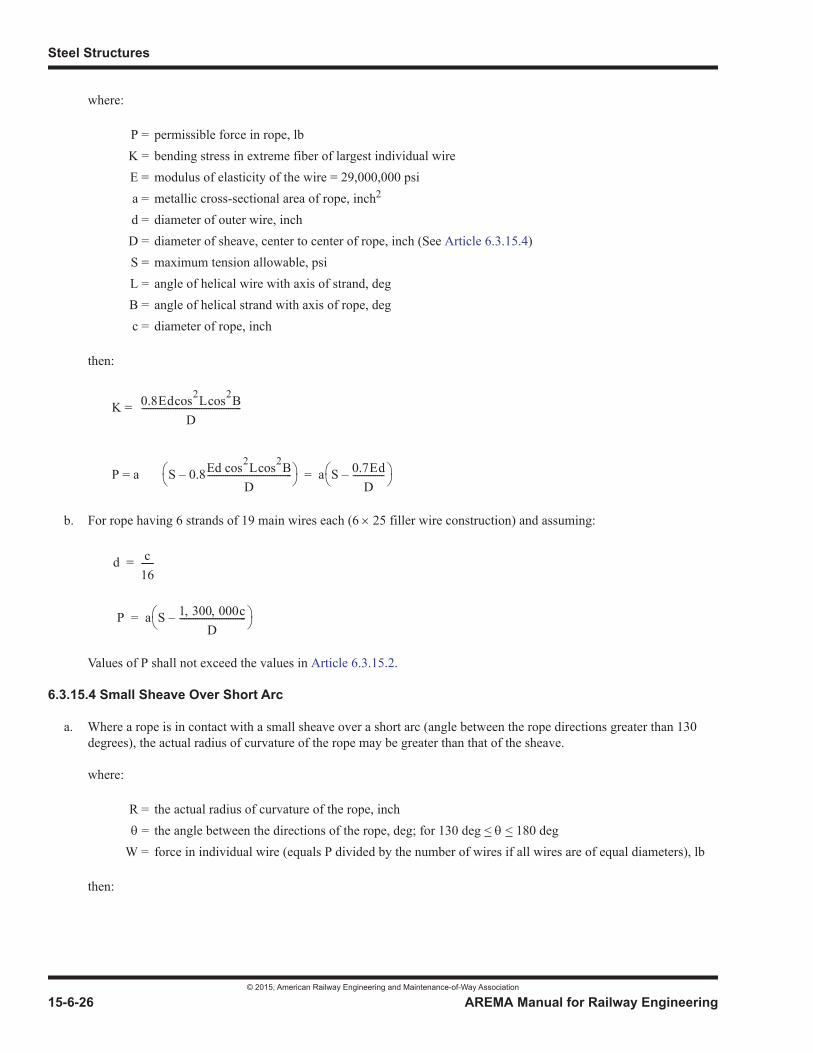
Steel Structures
© 2015, American Railway Engineering and Maintenance-of-Way Association
15-6-26 AREMA Manual for Railway Engineering
where:
then:
K =
P = a
b. For rope having 6 strands of 19 main wires each (6 25 filler wire construction) and assuming:
Values of P shall not exceed the values in Article 6.3.15.2.
6.3.15.4 Small Sheave Over Short Arc
a. Where a rope is in contact with a small sheave over a short arc (angle between the rope directions greater than 130 degrees), the actual radius of curvature of the rope may be greater than that of the sheave.
where:
then:
P = permissible force in rope, lbK = bending stress in extreme fiber of largest individual wireE = modulus of elasticity of the wire = 29,000,000 psia = metallic cross-sectional area of rope, inch2
d = diameter of outer wire, inchD = diameter of sheave, center to center of rope, inch (See Article 6.3.15.4)S = maximum tension allowable, psiL = angle of helical wire with axis of strand, deg B = angle of helical strand with axis of rope, deg c = diameter of rope, inch
R = the actual radius of curvature of the rope, inch = the angle between the directions of the rope, deg; for 130 deg < < 180 deg
W = force in individual wire (equals P divided by the number of wires if all wires are of equal diameters), lb
0.8Edcos2Lcos2BD
---------------------------------------------
S 0.8Ed cos2Lcos2BD
--------------------------------------– a S 0.7EdD
--------------–=
d c16------=
P a S 1 300 000cD
------------------------------–=

Movable Bridges
© 2015, American Railway Engineering and Maintenance-of-Way Association
AREMA Manual for Railway Engineering 15-6-27
1
3
4
b. If R is greater than the radius of the sheave, 2R should be used in place of D in the formulas of Article 6.3.15.3.
SECTION 6.4 BASIC ALLOWABLE STRESSES AND HYDRAULIC PRESSURES
6.4.1 STRUCTURAL PARTS (1993) R(2010)
Structural parts shall be proportioned by the requirements of Part 1, Design.
6.4.2 MACHINERY PARTS (2013)1
a. Table 15-6-2 shows the allowable stresses, psi, which shall be used for machinery and similar parts, except as modified by paragraph d.
b. Table 15-6-3 shows the allowable bending stresses, psi, which shall be used for trunnions.
1 See Part 9 Commentary
Table 15-6-2. Allowable Machinery Stresses
MaterialTension orBending
Compression(Note 1)
FixedBearing Shear
Structural carbon steel, ASTM A36 or A709 Grade 3612,000 16,000 6,000
Forged carbon steel, ASTM A668, Class D, except for keys 15,000 18,000 7,500
Forged carbon steel, ASTM A668, Class D, for keys – – 15,000 7,500
R d2
4.252---cos
---------------------------- EW-----=
12 000 55lr--–
15 000 65lr--–
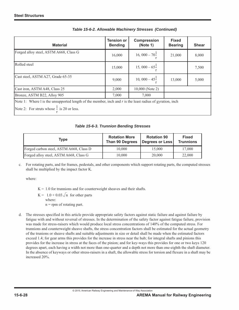
Steel Structures
© 2015, American Railway Engineering and Maintenance-of-Way Association
15-6-28 AREMA Manual for Railway Engineering
c. For rotating parts, and for frames, pedestals, and other components which support rotating parts, the computed stresses shall be multiplied by the impact factor K.
where:
d. The stresses specified in this article provide appropriate safety factors against static failure and against failure by fatigue with and without reversal of stresses. In the determination of the safety factor against fatigue failure, provision was made for stress-raisers which would produce local stress concentrations of 140% of the computed stress. For trunnions and counterweight sheave shafts, the stress concentration factors shall be estimated for the actual geometry of the trunions or sheave shafts and suitable adjustments in size or detail shall be made when the estimated factors exceed 1.4; for gear arms this provides for the increase in stress near the hub; for integral shafts and pinions this provides for the increase in stress at the faces of the pinion; and for key-ways this provides for one or two keys 120 degrees apart, each having a width not more than one-quarter and a depth not more than one-eighth the shaft diameter. In the absence of keyways or other stress-raisers in a shaft, the allowable stress for torsion and flexure in a shaft may be increased 20%.
Forged alloy steel, ASTM A668, Class G16,000 21,000 8,000
Rolled steel15,000 7,500
Cast steel, ASTM A27, Grade 65-359,000 13,000 5,000
Cast iron, ASTM A48, Class 25 2,000 10,000 (Note 2)Bronze, ASTM B22, Alloy 905 7,000 7,000Note 1: Where l is the unsupported length of the member, inch and r is the least radius of gyration, inch
Note 2: For struts whose is 20 or less.
Table 15-6-3. Trunnion Bending Stresses
Type Rotation MoreThan 90 Degrees
Rotation 90 Degrees or Less
FixedTrunnions
Forged carbon steel, ASTM A668, Class D 10,000 15,000 17,000Forged alloy steel, ASTM A668, Class G 10,000 20,000 22,000
K = 1.0 for trunnions and for counterweight sheaves and their shafts.K = for other parts
where:n = rpm of rotating part.
Table 15-6-2. Allowable Machinery Stresses
MaterialTension orBending
Compression(Note 1)
FixedBearing Shear
16 000 70lr--–
15 000 65lr--–
10 000 45lr--–
lr--
1.0 0.03 n+
(Continued)
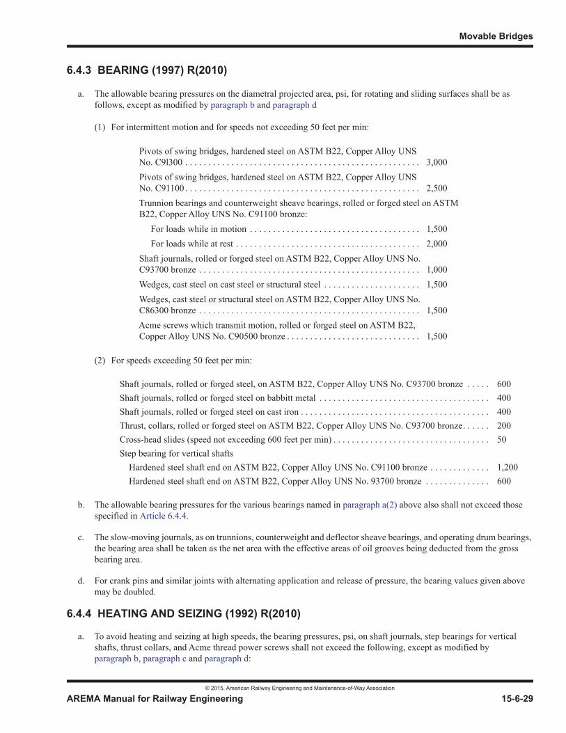
Movable Bridges
© 2015, American Railway Engineering and Maintenance-of-Way Association
AREMA Manual for Railway Engineering 15-6-29
1
3
4
6.4.3 BEARING (1997) R(2010)
a. The allowable bearing pressures on the diametral projected area, psi, for rotating and sliding surfaces shall be as follows, except as modified by paragraph b and paragraph d
(1) For intermittent motion and for speeds not exceeding 50 feet per min:
(2) For speeds exceeding 50 feet per min:
b. The allowable bearing pressures for the various bearings named in paragraph a(2) above also shall not exceed those specified in Article 6.4.4.
c. The slow-moving journals, as on trunnions, counterweight and deflector sheave bearings, and operating drum bearings, the bearing area shall be taken as the net area with the effective areas of oil grooves being deducted from the gross bearing area.
d. For crank pins and similar joints with alternating application and release of pressure, the bearing values given above may be doubled.
6.4.4 HEATING AND SEIZING (1992) R(2010)
a. To avoid heating and seizing at high speeds, the bearing pressures, psi, on shaft journals, step bearings for vertical shafts, thrust collars, and Acme thread power screws shall not exceed the following, except as modified by paragraph b, paragraph c and paragraph d:
Pivots of swing bridges, hardened steel on ASTM B22, Copper Alloy UNS No. C9l300 . . . . . . . . . . . . . . . . . . . . . . . . . . . . . . . . . . . . . . . . . . . . . . . . . . . 3,000Pivots of swing bridges, hardened steel on ASTM B22, Copper Alloy UNS No. C91100 . . . . . . . . . . . . . . . . . . . . . . . . . . . . . . . . . . . . . . . . . . . . . . . . . . . 2,500Trunnion bearings and counterweight sheave bearings, rolled or forged steel on ASTM B22, Copper Alloy UNS No. C91100 bronze: For loads while in motion . . . . . . . . . . . . . . . . . . . . . . . . . . . . . . . . . . . . . 1,500 For loads while at rest . . . . . . . . . . . . . . . . . . . . . . . . . . . . . . . . . . . . . . . . 2,000Shaft journals, rolled or forged steel on ASTM B22, Copper Alloy UNS No. C93700 bronze . . . . . . . . . . . . . . . . . . . . . . . . . . . . . . . . . . . . . . . . . . . . . . . . 1,000Wedges, cast steel on cast steel or structural steel . . . . . . . . . . . . . . . . . . . . . 1,500Wedges, cast steel or structural steel on ASTM B22, Copper Alloy UNS No. C86300 bronze . . . . . . . . . . . . . . . . . . . . . . . . . . . . . . . . . . . . . . . . . . . . . . . . 1,500Acme screws which transmit motion, rolled or forged steel on ASTM B22, Copper Alloy UNS No. C90500 bronze . . . . . . . . . . . . . . . . . . . . . . . . . . . . . 1,500
Shaft journals, rolled or forged steel, on ASTM B22, Copper Alloy UNS No. C93700 bronze . . . . . 600Shaft journals, rolled or forged steel on babbitt metal . . . . . . . . . . . . . . . . . . . . . . . . . . . . . . . . . . . . . 400Shaft journals, rolled or forged steel on cast iron . . . . . . . . . . . . . . . . . . . . . . . . . . . . . . . . . . . . . . . . . 400Thrust, collars, rolled or forged steel on ASTM B22, Copper Alloy UNS No. C93700 bronze. . . . . . 200Cross-head slides (speed not exceeding 600 feet per min) . . . . . . . . . . . . . . . . . . . . . . . . . . . . . . . . . . 50Step bearing for vertical shafts Hardened steel shaft end on ASTM B22, Copper Alloy UNS No. C91100 bronze . . . . . . . . . . . . . 1,200 Hardened steel shaft end on ASTM B22, Copper Alloy UNS No. 93700 bronze . . . . . . . . . . . . . . 600
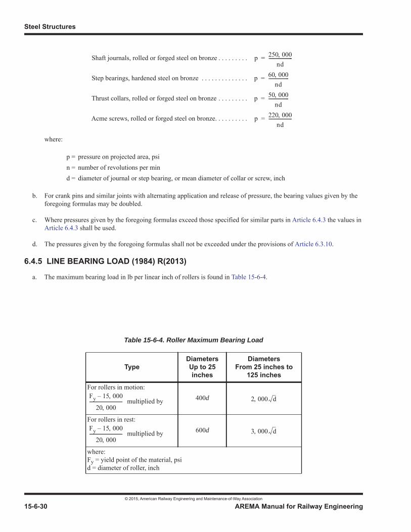
Steel Structures
© 2015, American Railway Engineering and Maintenance-of-Way Association
15-6-30 AREMA Manual for Railway Engineering
where:
b. For crank pins and similar joints with alternating application and release of pressure, the bearing values given by the foregoing formulas may be doubled.
c. Where pressures given by the foregoing formulas exceed those specified for similar parts in Article 6.4.3 the values in Article 6.4.3 shall be used.
d. The pressures given by the foregoing formulas shall not be exceeded under the provisions of Article 6.3.10.
6.4.5 LINE BEARING LOAD (1984) R(2013)
a. The maximum bearing load in lb per linear inch of rollers is found in Table 15-6-4.
Shaft journals, rolled or forged steel on bronze . . . . . . . . .
Step bearings, hardened steel on bronze . . . . . . . . . . . . . .
Thrust collars, rolled or forged steel on bronze . . . . . . . . .
Acme screws, rolled or forged steel on bronze. . . . . . . . . .
p = pressure on projected area, psin = number of revolutions per mind = diameter of journal or step bearing, or mean diameter of collar or screw, inch
Table 15-6-4. Roller Maximum Bearing Load
TypeDiametersUp to 25 inches
DiametersFrom 25 inches to
125 inches
For rollers in motion:
multiplied by 400d
For rollers in rest:
multiplied by 600d
where:Fy = yield point of the material, psid = diameter of roller, inch
p 250 000nd
---------------------=
p 60 000nd
------------------=
p 50 000nd
------------------=
p 220 000nd
---------------------=
Fy 15 000–
20 000----------------------------- 2 000 d
Fy 15 000–
20 000----------------------------- 3 000 d

Movable Bridges
© 2015, American Railway Engineering and Maintenance-of-Way Association
AREMA Manual for Railway Engineering 15-6-31
1
3
4
b. The foregoing values are for rollers and bearing surfaces of the same materials. If the rollers and bearing surfaces are of different materials, the lower value of Fy shall be used.
c. For rollers of trunnion and counterweight sheave roller bearings, the maximum bearing stress in lb per linear inch of roller shall be 3,000 d, where d is the diameter of the roller, inch. One-fifth of the rollers shall be taken as effective in carrying the load.
6.4.6 SHAFTS (1984) R(2010)
a. Bending stresses in circular shafts, trunnions, and axles shall be determined by the following formulas:
where:
b. For values of K and allowable stresses with and without keyways, or other stress-raisers, see Article 6.4.2.
6.4.7 BOLTS IN TENSION (1984) R(2003)
a. Bolts in tension in machinery parts shall be designed by assuming the effective area of the threaded portion to be:
A = An – (a 2D)
where:
b. This formula takes account of the fact that the initial stress in a 1/2 inch bolt, produced by tightening the nut, frequentlyequals or exceeds the yield point of the material.
c. For ANSI coarse threads, the formula reduces to:
f = extreme fiber stress in tension or compression, psiS = shear, psid = diameter of shaft at the section considered, inch
M = simple bending moment computed for the distance center to center of bearing, inch lbT = simple torsional moment, inch lb
A = effective area of threaded portion, square inchAn = net area at root of thread, square inch
a = net area of 1/2 inch bolt at root of thread, square inchD = nominal diameter of threaded portion, inch
f 16K
d3---------- M M2 T2++=
S 16K
d3---------- M2 T2+=
A An14---D–=
Steel Structures
© 2015, American Railway Engineering and Maintenance-of-Way Association
15-6-32 AREMA Manual for Railway Engineering
6.4.8 HYDRAULIC SYSTEMS AND COMPONENTS (1984)1 R(2010)
6.4.8.1 Allowable System Pressures
a. The hydraulic system shall be designed and hydraulic components proportioned such that the maximum allowable system pressures shall not exceed the following, except as otherwise permitted by prior written approval of the Company.
b. Normal operation shall be defined as operation against loads specified in Article 6.3.6a(1). Operation against maximum specified loads shall be defined as operation against loads specified in Article 6.3.6a(2) and Article 6.3.6a(3). Holding against maximum specified wind loads shall be defined as holding the movable span in the fully open position, static condition, against the loads specified in Article 6.3.6e.
6.4.8.2 Pressure Ratings for Hydraulic Components
a. Minimum working pressure ratings for hydraulic components shall be as follows, except as otherwise permitted by prior written approval of the Company.
b. Working pressure rating shall be defined as the maximum allowable continuous operating pressure for the component. For pipe, tubing, flexible hose and fittings the working pressure ratings are equal to the burst pressure rating divided by a minimum factor of safety of 4. For cylinders the working pressure rating shall be equal to the NFPA theoretical static failure pressure rating as required by Article 6.5.37.11 divided by a minimum factor of safety of 3.33. For pumps, valves and other components the working pressure rating is equal to the maximum allowable peak (intermittent) pressure rating divided by a minimum factor of safety of 1.5.
c. The minimum factors of safety designated in paragraph b apply to systems having light to moderate operating shock loads during operation resulting in short duration peak system pressures no greater than two times the allowable maximum operating pressure against Conditions B or C loads, whichever is greater. For systems having higher shock load pressures, the factors of safety shall be increased proportionally.
1 See Part 9 Commentary
Normal operation . . . . . . . . . . . . . . . . . . . . . . . . . . . . . . . 1,000 psiOperation against maximum specified loads . . . . . . . . . . 2,000 psiHolding against maximum specified wind loads . . . . . . . 3,000 psi
Pipe, tubing and their fittings . . . . . . . . . . . . . . . . . . . . . . . . . . . . . . . . . . . . . 3,000 psiFlexible hose and hose fittings: For pressure lines . . . . . . . . . . . . . . . . . . . . . . . . . . . . . . . . . . . . . . . . . . . . 5,000 psi For drain lines. . . . . . . . . . . . . . . . . . . . . . . . . . . . . . . . . . . . . . . . . . . . . . . 2,000 psiCylinders, pumps, valves and all other components . . . . . . . . . . . . . . . . . . . 3,000 psi
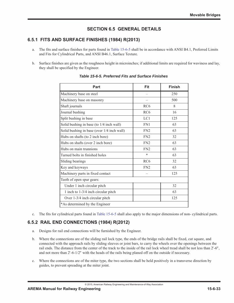
Movable Bridges
© 2015, American Railway Engineering and Maintenance-of-Way Association
AREMA Manual for Railway Engineering 15-6-33
1
3
4
SECTION 6.5 GENERAL DETAILS
6.5.1 FITS AND SURFACE FINISHES (1984) R(2013)
a. The fits and surface finishes for parts found in Table 15-6-5 shall be in accordance with ANSI B4.1, Preferred Limits and Fits for Cylindrical Parts, and ANSI B46.1, Surface Texture.
b. Surface finishes are given as the roughness height in microinches; if additional limits are required for waviness and lay, they shall be specified by the Engineer.
c. The fits for cylindrical parts found in Table 15-6-5 shall also apply to the major dimensions of non- cylindrical parts.
6.5.2 RAIL END CONNECTIONS (1984) R(2012)
a. Designs for rail end connections will be furnished by the Engineer.
b. Where the connections are of the sliding rail lock type, the ends of the bridge rails shall be fixed, cut square, and connected with the approach rails by sliding sleeves or joint bars, to carry the wheels over the openings between the rail ends. The distance from the center of the track to the inside of the rail lock wheel tread shall be not less than 2 -6 ,and not more than 2 -6-1/2 with the heads of the rails being planed off on the outside if necessary.
c. Where the connections are of the miter type, the two sections shall be held positively in a transverse direction by guides, to prevent spreading at the miter joint.
Table 15-6-5. Preferred Fits and Surface Finishes
Part Fit Finish
Machinery base on steel – 250Machinery base on masonry – 500Shaft journals RC6 8Journal bushing RC6 16Split bushing in base LC1 125Solid bushing in base (to 1/4 inch wall) FN1 63Solid bushing in base (over 1/4 inch wall) FN2 63Hubs on shafts (to 2 inch bore) FN2 32Hubs on shafts (over 2 inch bore) FN2 63Hubs on main trunnions FN2 63Turned bolts in finished holes * 63Sliding bearings RC6 32Key and keyways FN2 63Machinery parts in fixed contact – 125Teeth of open spur gears: Under 1 inch circular pitch 32 1 inch to 1-3/4 inch circular pitch 63 Over 1-3/4 inch circular pitch 125*As determined by the Engineer

Steel Structures
© 2015, American Railway Engineering and Maintenance-of-Way Association
15-6-34 AREMA Manual for Railway Engineering
d. Provisions shall be made so that the rail locks can be closed only when the span is seated and the rail end sections properly engaged.
e. The edges of all drilled holes in rail locks and in the rail ends adjacent thereto shall be chamfered approximately 1/16 inch. All reentrant angles in these appurtenances shall be filleted.
6.5.3 AIR BUFFERS (1997) R(2012)
a. Air buffers to aid in seating the movable span shall be provided as specified in Article 6.5.35.4, Article 6.5.36.4, and Article 6.8.19.
b. The inside diameter of the cylinder of the air buffer shall not be less than 10 inches, and the travel of the piston not lessthan 24 inches.
c. There shall be three cast iron packing rings for each piston.
d. Each air buffer shall be provided with a needle valve and a check valve, and these shall be suitable for sustaining for short intervals air pressures of 1,000 psi and temperatures of 800 degrees F.
e. As an alternative to air buffers, industrial type shock absorbers may be provided, if specified by the Engineer in the contract documents.
f. Air buffers or shock absorbers may be omitted if the control system is designed to seat the span smoothly at a slow speed which will not create undue impact.
6.5.4 COUNTERWEIGHTS (2003) R(2012)
a. Counterweights normally shall be made of concrete, supported by a steel frame or, preferably, enclosed in a steel box. Boxes shall be rigidly braced and stiffened to prevent warping or bulging. All surfaces of the boxes in contact with the concrete shall be provided with open holes (about l square inch to each 10 square feet of surface) to permit escape of water from the box as the concrete cures, or otherwise a low-slump concrete shall be used and any excess water drawn off as the concrete is placed. In the design of counterweight attachments, details which may produce fatigue due to vibration of the structure shall be avoided.
b. Concrete counterweights not enclosed in steel boxes shall be adequately reinforced.
c. Counterweights shall be made so as to be adjusted easily for variations in the weight of the span and in the unit weight of the concrete. Usually this shall be done by adding or taking off properly located cast iron or concrete balance blocks. Pockets shall be provided in the counterweights to house the balance blocks necessary to care for not less than 3.5% underrun and 5% overrun in the weight of the span. Each completed counterweight shall contain not less than 1% of its weight in balance blocks, arranged so as to be readily removable for future adjustment. Additional balance blocks for future adjustment in the amount of 0.5% of the weight of the counterweight shall also be provided and shall be stored at the site as directed by the Engineer. All balance blocks shall be firmly held in place so that they will not move during the operation of the bridge. Balance blocks shall be provided with recessed handles or recesses on the underside of the blocks for projecting handles and shall weigh not more than 100 lb each. Balance blocks shall be furnished only as necessary to meet the specified requirements for future adjustment and to secure the required balance of the span and counterweights.
d. Pockets in counterweights shall be provided with drain holes of not less than 2 inches diameter. The pockets shall be covered. The cover, its fastenings and frame shall be of metal. The cover shall be weatherproof.
6.5.5 CONCRETE (1984) R(2012)
a. Concrete, unless otherwise stipulated, shall conform to the requirements of Chapter 8, Concrete Structures and Foundations, shall be made with Type II cement, and shall be proportioned as directed by the Engineer, with not more
Movable Bridges
© 2015, American Railway Engineering and Maintenance-of-Way Association
AREMA Manual for Railway Engineering 15-6-35
1
3
4
than 6 gal of water per sack of cement. Where heavy concrete is required for counterweights, the coarse aggregate shall be trap rock, magnetic iron ore, or other heavy material, or the concrete may incorporate steel punchings or scrap metal, and mortar composed of 1 part of cement and 2 parts of fine aggregate. The maximum weight of heavy concrete shall be 315 lb per cubic foot but preferably not more than 275 lb per cubic foot. Heavy concrete shall be placed in layers and consolidated with vibrators or tampers. Methods of mixing and placing shall be such as to give close control of the unit weight of the concrete and uniformity of unit weight throughout the mass. Counterweights containing punchings or scrap metal or iron ore aggregates shall be enclosed in steel boxes. Concrete for counterweights should be non air-entrained to permit better control of density.
b. Concrete counterweights of the revolving type shall be poured continuously where practicable.
c. For ascertaining the weight of the concrete, test blocks having a volume of not less than 4 cubic feet for ordinary concrete, and 1 cubic foot for heavy concrete, and 1 cubic foot for the mortar for heavy concrete, shall be cast at least 30 days before concreting is begun. Two test blocks of each kind shall be provided, and one weighed immediately after casting and the other after it has seasoned.
6.5.6 MACHINERY IN GENERAL (1984) R(2013)
a. Machinery shall be simple, and of substantial construction. The configuration and arrangement of the components shall permit easy erection, adjustment, inspection, lubrication, cleaning, painting, and replacement of worn or defective parts.
b. Fastenings shall be adequate to hold the parts in place under all conditions of service. Mounting bolts shall be of such size that they may be preloaded to not less than 150% of the maximum operating design load.
c. Where practicable, machinery units shall be assembled in enclosed rigid housings or castings, or shall be shop assembled on rigid steel bases.
6.5.7 JOURNAL BEARINGS (1984) R(2013)
a. Bearings shall be placed close to the points of loading and located so that the bearing pressure shall be as nearly uniform as possible.
b. Journal bearings shall be of the split type with one half recessed into the other half. The length of a bearing shall be not less than its diameter. The base halves of bearings for gear trains and for mating gears and pinions shall be in one piece. The caps of bearings shall be secured to the bases with turned bolts with square heads recessed into the base and with double hexagonal nuts. The nuts shall bear on finished bosses or spot-faced seats. Fits and finishes for caps and bolts shall be as specified in Article 6.5.1.
c. Provision shall be made for the aligning of bearings during erection by means of shims and for the adjustment of the caps by means of laminated liners or other effective device.
d. Large bearings shall be provided with effective means for cleaning without dismantling the parts.
6.5.8 LININGS (1984) R(2013)
a. Journal bearings normally shall have bronze linings; other lightly loaded bearings may have bronze or babbitt metal linings. For split bearings, the lining shall be in halves and shall be provided with an effective device to prevent its rotation under load. The force tending to cause rotation shall be taken as 1/16 of the maximum load on the bearing and as acting at the outer circumference of the lining. There shall be 1/4 inch clearance between the lining of the cap and the lining of the base into which laminated liners shall be placed. The inside longitudinal corners of both halves shall be rounded or chamfered, except for a distance of 3/8 inch from each end or shaft fillet tangent point.
Steel Structures
© 2015, American Railway Engineering and Maintenance-of-Way Association
15-6-36 AREMA Manual for Railway Engineering
b. Linings for solid bearings shall be in one piece and shall be pressed into the bearing bore and effectively held against rotation.
6.5.9 STEP BEARINGS (1984) R(2013)
The bearing ends of vertical shafts running in step bearings shall be of hardened steel, and shall bear on bronze disks.
6.5.10 ROLLER BEARINGS FOR HEAVY LOADS (2003)
a. Roller bearings may be used to support the trunnions of bascule bridges, the counterweight sheave shafts of vertical lift bridges, and similar shafts carrying heavy loads. Roller bearings shall not be used on trunnions of bascule bridges that are subject to uplift due to live load. Each roller bearing shall be of a type, or shall be so mounted, that the deflection of the shaft will produce no overloading of any part of the bearing or housing. The bearing rollers shall be relatively short for their diameter, shall be closely spaced in bronze cages, and shall run between hardened-steel races, mounted in the housing and on the shaft. The bearing mountings on each shaft shall be such that the shaft shall be restrained from axial movement by one mounting, and shall be free to move in the other mounting.
b. The ratio of length to diameter of any roller or roller segment shall not exceed 3.25. For segmented rollers the ratio of total length of roller to diameter shall not exceed 6.5.
c. Cylindrical roller bearings shall be provided with anti-friction thrust bearings capable of restraining an axial thrust equal to l5% of the total radial load on the shaft or trunnion. Spherical or tapered roller bearings shall be proportioned for an axial load equal to 15% of the total radial load on the shaft or trunnion combined with the radial load on the bearing.
d. Each roller bearing shall be mounted in an oil- and water-tight steel housing, which shall be provided with means for replenishing the lubricant and arranged for convenient access for thorough cleaning of the operating parts.
e. Rollers and races shall be of special steel proposed by the manufacturer, which shall have Rockwell C hardness not less than 58 for the rollers and not less than 56 for the races. Bearings shall be made by a manufacturer of established reputation who has had bearings of comparable size of the same materials and type in successful service for at least 10 years.
6.5.11 ROLLER AND BALL BEARINGS (1997) R(2003)
a. Roller and ball bearings shall be so sized that under the loads and resistances specified in Section 6.3, Loads, Forces and Stresses, and at the average running speed at which the bearing is applied, the B-10 life shall be at least 40,000 hours. (B-10 life shall be as defined by the ABMA and shall be the time for which 90% of a group of identical bearings will survive under the given loading conditions).
b. Bearings separately mounted in pillow blocks shall be self-aligning. Housings shall be cast steel and may be one piece or split on the center line. Where pillow blocks are exposed to dirt or moisture, seals shall be provided. Split housings shall have positive means to align the cap with the base.
When loads are in a direction other than directly into the base, the housings, cap bolts, alignment devices for split housings, and the base mounting bolts shall have adequate strength and stiffness to resist the lateral and uplift components of the loads without adverse effects on the roller and ball bearing elements.
6.5.12 SPEED REDUCERS (2010)
a. Main drive train helical, herringbone and bevel gear speed reducers shall be designed and manufactured in accordance with the requirements of AGMA Standard 6010.
Movable Bridges
© 2015, American Railway Engineering and Maintenance-of-Way Association
AREMA Manual for Railway Engineering 15-6-37
1
3
4
b. Gears shall be finished to AGMA 2000 quality 10 or better.
c. Gear teeth shall be through hardened.
d. Anti-friction bearings shall be used on all shafts and shall have a minimum B-10 rating of 40,000 hours. They shall be automatically and continuously lubricated. An independently driven lubrication system shall be provided when the operating speed of the reducer is too slow for normal integral lubrication.
e. Housings shall have provisions for filling, draining and ventilation.
f. Provision shall be made for indicating the oil level by means of a sight gage. The recommended oil level shall be permanently marked on the housing, adjacent to the sight gage.
g. A gasketed inspection cover, preferably located above the static oil level, shall be provided.
h. The reducer shall be able to withstand a momentary overload equal to three times the normal full load torque of the driving motor(s) without any component reaching yield. To achieve this, the minimum service factors shall be 1.0 for durability and 1.5 for strength (bending) based on the full load torque/horsepower of the electric motor(s).
i. Reducers driven by internal combustion engines or hydraulic motors shall be selected considering the speed-torque characteristics of the engine or motor.
j. Pinions shall be proportioned so that the root diameter of the pinion is not smaller in diameter than the diameter of the journals for the pinion shaft.
k. Base plates for the reducers shall be large enough to give unobstructed access for drilling and reaming the mounting holes.
6.5.13 LUBRICATION (2008)1
a. Provision shall be made for effective lubrication of sliding surfaces and of roller and ball bearings. Lubricating devices shall be readily accessible.
b. Each sliding bearing requiring lubrication shall have a high pressure grease fitting, containing a small receiving ball or cone check valve, made of steel, that will receive the grease and close against back pressure. These fittings shall be connected to the linings of bearings by means of corrosion resisting pipe, which shall be screwed into the lining through a hole in the cap. Where the bearings are not readily accessible, the fittings shall be placed where they will be accessible, and shall be connected to the bearings by means of corrosion resisting pipe.
c. Grease ducts shall be so located that the lubricant will tend to flow, by gravity, toward the bearing surface. Grooves shall be provided, wherever necessary, for the proper distribution of the lubricant.
d. Grooves for trunnion bearings may be cut in either the shaft or the lining. Such grooves shall be straight, parallel to the axis of the shaft, and for large bearings no fewer than three shall be provided. Grooves shall be so located that the entire bearing surface will be swept by lubricant in one movement of opening or closing the bridge, or in 90 degree rotation of the shaft, whichever is less. Each such groove shall be served with lubricant by a separate pressure fitting. The grooves shall be of such size that a 5/16 inch diameter wire will lie wholly within the groove and their bottoms shall be rounded to a 1/4 inch radius. The grooves shall be accessible for cleaning with a wire.
e. Grooves for counterweight sheave sleeve bearings may be in accordance with the requirements of the foregoing paragraph but should be spiral grooves cut in the lining and served with pressure fittings. A cleanout hole shall be
1 See Part 9 Commentary
Steel Structures
© 2015, American Railway Engineering and Maintenance-of-Way Association
15-6-38 AREMA Manual for Railway Engineering
provided in the bearing base and connected to the lowest point of the spiral grooves so that the journal surface can be cleaned and the grooves flushed out.
f. In disk bearings, straight grooves shall be cut in the upper of the two rubbing surfaces in contact. The grooves shall be not less than 1/4 inch wide and deep, and the corners shall be rounded to a radius not less than half the width of the groove. The corners at the bottom of the grooves shall be filleted to eliminate all sharp corners.
g. Small bearings with light bearing pressures and slow or intermittent motion, and not readily accessible, may be lubricated with self-lubricating bushings. Such bushings shall be of a type which will not be injured by the application of oil. The bearings shall be provided with oil holes for emergency lubrication, and the oil holes shall be fitted with readily removable screw plugs.
h. Hand-operated grease guns having a capacity of 12 oz shall be provided to service all lubrication fittings. There shall also be provided portable loaders of 25-lb capacity and a loader for use with 100-lb grease drums. All necessary adapters shall be provided for the equipment.
i. Two guns shall be furnished for each swing and bascule span, and three guns for each lift span. One portable loader and one drum loader shall be furnished for each movable bridge.
j. All lubricants for a given component shall be chemically compatible, including the lubricant used in manufacture and the lubricant that will be field applied. For any component on which a new lubricant is to be applied that is not chemically compatible with the existing lubricant, all traces of the existing lubricant shall be thoroughly cleaned and flushed from the component before applying the new lubricant.
6.5.14 SHAFTS (1983) R(2003)
a. For shafts supporting their own weight only, the unsupported length of the shaft shall not exceed:
where:
b. Shafts likely to be thrown out of line by the deflection of the supporting structure shall be made in non-continuous lengths. The arrangement should be such that only angular misalignment need be provided by the couplings with offset misalignment provided for by a floating shaft. Each length of shaft should rest in not more than two bearings.
c. Shafts shall be proportioned so that the angular strain in degrees per foot of length under the maximum loads will not exceed the following limits:
where:
L = length of shaft between bearings, inchd = diameter of shaft, inch
(1) For shafting . . . . . . . . . . . . . . . . . . . . . . . . . . . . . . . . . . . . . . . . . . . .
(2) For more rigid drives where less spring is desirable,as in shafts driving end-lifting devices . . . . . . . . . . . . . . . . . . . . . . . . 0.08
d = the shaft diameter, inch
L 80 d2 3=
0.6d
-------

Movable Bridges
© 2015, American Railway Engineering and Maintenance-of-Way Association
AREMA Manual for Railway Engineering 15-6-39
1
3
4
NOTE: Where the diameter exceeds 7.5 inches, requirement 1 governs.
d. Line shafts connecting the machinery at the center of the bridge with that at the ends shall be designed to run at fairly high speed, the speed reduction being made in the machinery at the end. The maximum speed of line shafts shall not exceed 2/3 of the critical speed of any section of the shaft.
e. Shafts transmitting power for the operation of the bridge, and shafts 4 feet or more in length forming part of the operating machinery of rail locks and bridge locks, shall not be less than 2-1/2 inches dia.
f. Journals on cold-rolled shafting shall not be turned down. Pinions may be forged integral with their shafts.
6.5.15 SHAFT COUPLINGS (1983) R(2013)
a. Where practicable, all couplings used in connection with the machinery shall be standard manufactured flexible couplings placed close to the bearings.
b. Couplings between machinery units should be of the gear type, providing for angular misalignment or for both angular and offset misalignment.
c. Couplings connecting machinery shafts to electric motor or internal combustion engine shafts shall be flexible couplings, transmitting the torque through metal parts and providing for both misalignment and shock.
d. Machinery shafts supported and assembled so as to avoid any misalignment between the shafts may be connected by flange couplings. The bolt heads and nuts shall be seated in recesses or protected by flanges. The couplings shall be cylindrical.
e. Couplings used to connect instrument drives or other small units to large units shall preferably have short floating shafts between the units to minimize participation stresses in the small units.
f. All coupling and shaft fits and finishes shall meet the requirements of Article 6.5.1 for hubs on shafts. Couplings shall be keyed to the shafts. The couplings shall in all cases be fitted to their shafts in the shop.
6.5.16 LONGITUDINAL THRUST (1983) R(2003)
Wheels and similar parts shall be securely fastened, to prevent longitudinal movement, by set screws through the hub, or by clamps around the shaft. Provision shall be made to hold bevel gears and worm wheels against movement along the shaft. The axial thrust from bevel gears shall be taken by the shaft bearing by means of a loose bronze washer between the gear hub and the face of the bearing, or by an equivalent means.
6.5.17 COLLARS (1997) R(2003)
Collars shall be provided wherever necessary to prevent the shaft from moving axially. There shall be at least two set screws, 120 degrees apart, in each collar. The set screws shall have dog points, and the shafts shall be counterbored for the set screws.The edges of the holes shall be peened over the set screws after the collars are adjusted. Where a shaft or trunnion receives anaxial force, a thrust bearing shall be provided to prevent axial movement.
6.5.18 GEAR TEETH (1983) R(2003)
a. Gear teeth, unless specifically specified otherwise, shall be machine cut, shall be of the involute type, and shall have a pressure angle of 20 degrees. Gears in general shall have straight spur teeth of full depth. For special applications, stub teeth may be used. For tooth speeds over 1200 feet per min, and for tooth speeds over 500 feet per min, where quiet operation is desired, helical gears shall preferably be used. Helical gears shall be assembled in a common frame, shall
Steel Structures
© 2015, American Railway Engineering and Maintenance-of-Way Association
15-6-40 AREMA Manual for Railway Engineering
be fully enclosed in a metal housing, and shall run in oil; they shall be assembled so that one gear of each pair of mating gears may have a slight axial movement to permit operation at the correct location relative to the other gear. Unless otherwise specified, all gear teeth shall be cut from solid rims.
b. For full-depth spur gear teeth, the addendum shall be not more than 0.3183 of the circular pitch and the tooth thickness measured on the pitch circle shall be 0.495 of the circular pitch. For stub teeth, the addendum shall be not more than 0.2546 of the circular pitch.
c. The face width of a spur gear shall be not less than 1.5 times the circular pitch. The face width of a bevel gear shall be not more than one-third of the slant height of the pitch cone, nor more than 3 times the circular pitch at the middle section of the tooth.
d. The circular pitch of spur gears, other than motor pinions, transmitting power for moving the span, shall be not less than 1 inch, and for motor pinions not less than 3/4 inch. The circular pitch for main rack teeth shall be not less than 1-1/2 inches.
e. Pinions shall have not less than 15 teeth. Rack pinions should have not less than 17 teeth. Motor pinions should have not less than 19 teeth.
f. Helical gear teeth shall be cut to the same normal profile as spur gear teeth. The helical angle shall be not less than 23 degrees and not more than 30 degrees. The net width of face, measured parallel to the axis of the bore, shall be not less than 3 times the circular pitch nor more than 1.5 times the pitch diameter of the pinion.
6.5.19 STRENGTH OF GEAR TEETH (1983) R(2003)
a. In the design of spur gears, bevel gears, and helical gears, the load shall be taken as applied to only one tooth.
b. The tooth profile for spur, bevel and helical gears shall be the 20 degrees, full depth or stub, involute and shall be of theproportions stated in Article 6.5.18.
c. The allowable load on gear teeth shall conform to the following formulas:
(1) Spur gears and bevel gears:
(a) For full-depth involute teeth:
(b) For stub involute teeth:
(2) Helical teeth, full depth:
W psf 0.154 0.912n
-------------– 600600 V+-------------------=
W psf 0.178 1.033n
-------------– 600600 V+-------------------=
W 0.7psf 0.154 0.912n
-------------– 12001200 V+----------------------=
Movable Bridges
© 2015, American Railway Engineering and Maintenance-of-Way Association
AREMA Manual for Railway Engineering 15-6-41
1
3
4
where:
d. The effective face width for spur and bevel gears shall be the full face width up to 3 times the circular pitch; for greater face widths, the effective width shall be 3 times the circular pitch but not less than one-half the full width.
e. The effective face width for helical gears shall be the net active width of face measured parallel to the axis of the bore.
f. For calculating the strength of bevel gear teeth, the middle section of the tooth shall be taken. The number of teeth “n” in the above formulas for bevel gear teeth shall be the formative number which, for the pinion, is determined as follows:
where:
g. The basic allowable stresses, psi, for cut gear teeth of all types shall be:
h. The basic allowable stress, psi, for machine molded teeth shall be:
i. For racks and their pinions and for all other mating gears and pinions which are not supported in and shop-assembled in a common frame, the basic allowable stresses shall be decreased 20%.
W = allowable tooth load, lbp = circular pitch, inchs = permissible unit stress, psif = effective face width, inchn = number of teeth in gearV = velocity of pitch circle, feet per min.
np = actual number of teeth in pinionng = actual number of teeth in gear
Bronze . . . . . . . . . . . . . . . . . . . . . . . . . . . 9,000Cast steel . . . . . . . . . . . . . . . . . . . . . . . . . 16,000Class C forged carbon steel . . . . . . . . . . . 20,000Class D forged carbon steel. . . . . . . . . . . 22,500Forged alloy steels. . . . . . . . . . . . . . . . . . 60% of tensile yield point, but not more than
1/3 of ultimate tensile strength.
Cast steel . . . . . . . . . . . . . . . . . . . . . . . . . 8,000
n np 1 npng------
2+=
Steel Structures
© 2015, American Railway Engineering and Maintenance-of-Way Association
15-6-42 AREMA Manual for Railway Engineering
6.5.20 WORM GEARING (2003)
a. Except for the end and center wedges of swing bridges, worm gearing should not be used for transmitting power. In calculating the strength of worm gear teeth, the load transmitted shall be taken as equally distributed between two teeth. If used for span operating machinery, worm gearing shall be designed to be back driven without damage.
b. Worm gear reducers for transmitting power should be commercial units selected on the basis of their rating under the American Gear Manufacturers Association recommended practice. The helix angle of the worm shall be not less than 20 degrees. The worms shall be heat-treated alloy steel forgings and the gear shall be bronze. The thread of the worm shall be ground and polished, and the teeth of the gear shall be accurately cut to the correct profile. The worm and gear-thrust loads shall be taken by anti-friction bearings, mounted in water and oil tight housings. The unit shall be mounted in a steel or cast iron housing and the lubrication shall be continuous while in operation.
c. Worm gear units used for end and center wedges of swing bridges shall be self-locking.
6.5.21 SCREW GEARING AND CAMS (1983) R(2013)
a. Except for end lifts and center wedges of swing bridges, screw gearing should not be used for transmitting power.
b. Screws and nuts for transmitting power shall be cut with 29 degree general purpose Acme thread. Anti-friction bearings shall be provided to carry all thrust loads. The unit shall be mounted in an oil and watertight housing and provided with continuous lubrication. The screw and nut shall be made of dissimilar metals, preferably steel and bronze.
c. Cams and similar devices transmitting power by line or point contact shall not be used.
6.5.22 HUBS (1983) R(2010)
a. Where practicable, the length of all hubs shall be not less than the diameter of the bore, and for gears also not less than 1.25 times the width of the teeth. The thickness of the hub should not be less than 0.4 of the diameter of the bore.
b. Unless otherwise specified, all hub and shaft fits and finishes shall meet the requirements of Article 6.5.1. Hubs shall be provided with keys designed to carry the total torque.
c. Bascule trunnion hubs that are to fit tightly into structural parts shall have an ANSI Class FN2 fit therein, and shall be secured against rotation by keys or bolts.
6.5.23 KEYS AND KEYWAYS FOR MACHINERY PARTS (2003) R(2010)
a. Keys for securing machinery parts to shafts shall be parallel-faced, square or flat, except that tapered keys may be used to meet special requirements. All keys shall be fitted into keyways sunk into the hub and shaft. Preferably, the keyways in the shaft shall have closed ends, which shall be milled to a semi-circle equal to the width of the key. Keyways shall not extend into any bearing.
b. Keys that are not set into closed-end keyways shall be held by safety set screws, or other effective means; in vertical shafts, collars clamped about the shafts, or similar devices, shall be used.
c. In hubs of spoked wheels, the keyways shall be located in the centers of the spokes. If two keys are required, they shall be placed 120 degrees apart.
d. All keys shall have a width not greater than one-quarter of the shaft diameter and the thickness of flat keys shall be approximately three-quarters of their width.
Movable Bridges
© 2015, American Railway Engineering and Maintenance-of-Way Association
AREMA Manual for Railway Engineering 15-6-43
1
3
4
e. Details of keys and keyways shall conform to ANSI B17.1 except for the fit of keys which is covered in Table 15-6-5.
6.5.24 KEYS FOR TRUNNIONS (1983) R(2010)
a. The foregoing requirements for keys and keyways are for machinery parts, whose use is intended to develop the full torsional strength of the shaft.
b. For trunnions and similar parts which are designed chiefly for bending and bearing, the keys and keyways shall be proportioned simply to hold the trunnion from rotating. The force tending to cause rotation shall be taken as one-fifth of the load on the trunnion acting at the circumference of the trunnion.
6.5.25 BOLTS AND NUTS (2003) R(2014)
a. Bolts for connecting machinery parts to each other or to steel supporting members shall conform to one of the following types:
(1) Finished, high-strength bolts.
(2) Turned bolts, turned cap screws, and turned studs.
(3) High-strength turned bolts, turned cap screws, and turned studs.
b. Finished high-strength bolts shall meet the requirements of ASTM A449. High-strength bolts shall have finished bodies and regular hexagonal heads. Holes for high-strength bolts shall be not more than 0.01 inch larger than the actual diameter of individual bolts and will require drilling holes to match the tolerances for each bolt. The clearance shall be checked with 0.011 inch wire. The hole shall be considered too large if the wire can be inserted in the hole together with the bolt.
c. Turned bolts, turned cap screws, and turned studs shall have turned shanks and cut threads. Turned bolts shall have semi-finished, washer-faced, hexagonal heads and nuts. Turned cap screws shall have finished, washer-faced, hexagonal heads. Finished shanks of turned fasteners shall be 1/16 inch larger in diameter than the diameter of the thread, which shall determine the head and nut dimensions. The shanks of turned fasteners shall have Class LT1 fit in the finished holes in accordance with ANSI Standard B4.1. The material for the turned shank fasteners shall meet the requirements of ASTM A307, Grade A.
d. High-strength turned bolts, turned cap screws, and turned stud details shall be as specified in paragraph c, except that the material shall meet the requirements of ASTM A449.
e. Elements connected by bolts shall be drilled or reamed assembled to assure accurate alignment of the hole and accurate fit over the entire length of the bolt within the specified limit.
f. The dimensions of bolt heads, nuts, castle nuts, and hexagonal head cap screws shall be in accordance with ANSI Standard B18.2, Square and Hexagon Bolts and Nuts.
g. Heads and nuts for turned bolts, screws, and studs shall be heavy series.
h. The dimensions of socket-head cap screws and socket flathead cap screws shall conform to ANSI Standard B18.3. The screws shall be made of heat-treated alloy steel, cadmium-plated, and furnished with a self-locking nylon pellet embedded in the threaded section.
i. Threads for bolts, nuts, and cap screws shall conform to the coarse thread series and shall have a Class 2 tolerance for bolts and nuts or Class 2A tolerance for bolts and Class 2B tolerance for nuts in accordance with ANSI Standard B1.1, Unified Inch Screw Threads.

Steel Structures
© 2015, American Railway Engineering and Maintenance-of-Way Association
15-6-44 AREMA Manual for Railway Engineering
j. Bolt holes through unfinished surfaces shall be spotfaced for the head, nut, and washer, square with the axis of the hole.
k. Unless otherwise called for, bolt holes in machinery parts or connecting these parts to the supporting steel work shall be subdrilled at least 1/32 inch smaller in diameter than the bolt diameter. They shall be reamed for the proper fit at assembly or at erection with the steel work after the parts are correctly and finally assembled and aligned and the supporting steel work subdrilled.
l. Holes in shims and fills for machinery parts shall be reamed or drilled to the same tolerances as the connected parts at final assembly.
m. Positive locks of an approved type shall be furnished for nuts, except those of ASTM A449 bolts which are tensioned at installation to at least 70% of their required minimum tensile strength. If double nuts are used, they shall be used for connections requiring occasional opening or adjustment. If lock washers are used for securing, they shall be made of tempered steel and shall conform to the SAE regular dimensions. The material shall meet the SAE tests for temper and toughness.
n. High-strength bolts shall be installed with a hardened plain washer meeting ASTM F436 at each end.
o. Wherever possible, high-strength bolts connecting machinery parts to structural parts or other machinery parts shall be inserted through the thinner element into the thicker element.
p. Cotters shall conform to the SAE standard dimensions and shall be made of half-round stainless steel wire, ASTM A276, Type 316.
q. Anchor bolts connecting machinery parts to masonry shall be ASTM A307, Grade A or Grade C material, hot-dipped galvanized per ASTM A153. Bolts shall be as shown on the masonry drawings. Anchor bolts for new construction should be cast-in-place and not drilled. The Engineer shall specify the material and loading requirements for the given design condition. When these fasteners connect a mechanical component directly to the concrete, filler material must be put in the annular space between the bolt and the bolt hole in the machinery component. The filler material may be a non-shrink grout, tin based babbitt metal, or zinc.
r. Nuts shall be of material and grade to match or exceed the strength of the bolts on which they are used.
s. Fasteners shall be of North American manufacture and shall be clearly marked with the manufacturer’s designation.
6.5.26 SET SCREWS (1997) R(2010)
Set screws shall not be used for transmitting torsion; they may be used for holding keys or light parts in place. They shall besafety-type headless set screws with dog points, set in counterbored seats. Unless otherwise ordered, they shall be secured in position by peening over the holes, or by welding.
6.5.27 TAPPED HOLES (1983) R(2010)
Machinery parts shall not be joined together or mounted on structural supports by means of bolts or studs in tapped holes, except by special permission of the Engineer. This does not apply to joints in component parts of standard manufactured items.
6.5.28 SPRINGS (1983) R(2010)
Springs should not be used to actuate any moving part. For electric parts, preference will be given to those having the fewest springs.
Movable Bridges
© 2015, American Railway Engineering and Maintenance-of-Way Association
AREMA Manual for Railway Engineering 15-6-45
1
3
4
6.5.29 EQUALIZERS (1983) R(2002)
The net section back of the pinhole in equalizing levers shall be not less than the net section in tension required to carry theload on the pin. The net section through the pinhole shall be not less than 140% of the required net section in tension.
6.5.30 COVERS (2003)
a. Dust covers shall be provided where necessary to protect sliding and rotating surfaces and prevent dust from mixing with lubricants.
b. Gear safety guards shall be provided for gears in machinery houses.
c. Shaft safety guards shall be provided for shafts in machinery houses.
d. Where gears or sheaves are located where falling objects may foul them, they shall be protected by easily removed metal covers.
e. Counterweight sheave rims shall be covered to protect them from the weather.
6.5.31 SAFETY DEVICES (1983) R(2002)
Safety devices such as hand rails, chains and cages shall be installed where needed. Applicable safety regulations shall be observed.
6.5.32 DRAIN HOLES (1983) R(2002)
Drain holes not less than 1 inch diameter shall be provided at places where water is likely to collect.
6.5.33 COMPRESSED AIR DEVICES (2003)
Mechanical devices powered by compressed air may be used for the operation of center wedges, end lifts, centering devices, and sliding rail locks. Air motors may be used for emergency power for span operating machinery. Means shall be provided to keep compressed air systems free of condensed moisture and ice.
6.5.34 SPECIAL PROVISIONS FOR SWING BRIDGES (2003)1
6.5.34.1 Center Bearing
Center-bearing swing bridges shall be so designed that when the bridge is swinging, the entire weight of the moving span is carried on a center pivot, and when the bridge is closed, the trusses or girders rest at the center on wedges. Adjustment for height shall be provided.
6.5.34.2 Rim Bearing
a. The load on the rim girder of a rim-bearing or combined rim- and center-bearing swing bridge shall be distributed equally among the bearing points, which shall be spaced equally around the rim girder.
b. Rigid struts firmly anchored to the rim girder shall connect the rim girder to a center pivot. A strut shall be attached to the rim girder at each bearing point, and at intermediate points where required. No fewer than eight struts shall be used in any case.
1 See Part 9 Commentary
Steel Structures
© 2015, American Railway Engineering and Maintenance-of-Way Association
15-6-46 AREMA Manual for Railway Engineering
c. The rim girder shall be designed so that the load will be properly distributed over the rollers. For designing the girder, the loads shall be assumed to be distributed equally to all rollers. The span length shall be taken as the developed length of the girder between adjacent bearing points, and this length shall be considered fixed at both ends. The girder shall be designed in accordance with the requirements for plate girders.
d. The lower track shall be designed to distribute the roller load uniformly over the masonry.
6.5.34.3 Combined Bearing
In a combined rim and center-bearing swing bridge, a definite portion of the load, not less than 15%, shall be carried to the center pivot by radial girders attached rigidly to the center pivot and to the rim.
6.5.34.4 Shear Over Center
In swing bridges having a center truss panel, this panel shall be so designed that shear will not be carried past the center. Theweb members of such a panel shall be strong enough to secure the bridge against longitudinal wind pressure when it is open.
6.5.34.5 End Wedges and Center Wedges
End wedges of swing bridges shall be arranged to center the closed bridge accurately, unless a separate device is used to centerthe bridge. The end and center wedges shall be so designed that the action of the moving load cannot cause displacement of the end supports and wedges in case of failure or disconnection of the mechanism which actuates the end lift. The end and center wedges shall be so designed as to permit adjustment, and may be operated by the same mechanism. (See Commentary)
6.5.34.6 Rim Girders
a. Rim girders shall be provided with stiffeners on both sides of the web at points of concentrated loading. These stiffeners shall be milled or ground to fit tightly against both flanges. The distance between adjacent intermediate stiffeners shall not exceed 2 feet. On rim girders exceeding 5 feet depth, alternate intermediate stiffeners may extend only one-half the depth of the girder, unless required to be of full depth to stiffen the web. The thickness of the stiffeners shall be not less than one-eighth of their width. The tread plate for the rollers shall be securely fastened to the rim girder and shall be from 2 inches to 3 inches thick, depending on the weight of the bridge. The rim girder flange angles shall be not smaller than 6 4 . For welded construction, the flange plates shall not be less than 1 inch thick.
b. Provisions shall be made for jacking the entire span.
6.5.34.7 Center Pivots
a. Center pivots shall consist of disk bearings, upon which the span revolves, and supporting pedestals. Disk bearings shall consist of two disks, one of phosphor bronze and one of hardened steel.
b. Center pivots shall be so designed that the disks may be taken out and replaced while the bridge is closed, without interfering with the operation of trains over the bridge. The disks shall be so anchored that sliding will take place only at the surface of contact.
6.5.34.8 Balance Wheels
a. For power operated center bearing bridges, no fewer than eight wheels, running on a circular track, shall be provided to limit the tilting of the bridge and to carry the wind load to the track while the bridge is swinging. The balance wheel bearings shall be adjustable for height, preferably by shims between the superstructure and the seats of the bearings. For short, single track, hand operated bridges, four wheels may be used.
b. Fits and finishes for wheel hubs on shafts shall meet the requirements of Article 6.5.1. The axles shall rotate in bronze lined bearings, with means for lubrication.
Movable Bridges
© 2015, American Railway Engineering and Maintenance-of-Way Association
AREMA Manual for Railway Engineering 15-6-47
1
3
4
6.5.34.9 Rack and Track
The rack and track of swing bridges shall be made in sections, preferably not less than 6 feet long. The track shall be deep enough to ensure good distribution of the balance wheel or roller loads to the masonry, and not less than 4 inches for rim-bearing bridges. If a cast track is used and the loads are light, as in center bearing bridges, the rack and track segments shouldbe cast in one piece. In rim bearing bridges, the rack shall be cast separately from the track, so that the parts may be easilyremoved for repairs. The joints in the rack and track shall be staggered. The track shall be anchored to the masonry by bolts notless than 1-1/2 inches diameter, extending at least 12 inches into the masonry, and set in non-shrink grout. The track of hand operated, center bearing bridges shall have an ample number of anchor bolts so that the mortar or grout in which they are set will not be crushed by the tractive force developed when turning the bridge. Where center bearing bridges are operated by mechanical power, the track shall be anchored down by bolts, and the tractive force developed when turning the bridge shall be taken by lugs extending down into the masonry and set in non-shrink grout or concrete.
6.5.34.10 Main Pinion Shaft Bearings
a. Where two main pinions are used they shall be placed diametrically opposite, and where four pinions are used, they shall be placed in pairs which shall be diametrically opposite.
b. Each main pinion shaft shall be supported in a double bearing, which shall be provided with bolted caps, split linings, and liners, to permit easy removal of the pinion shaft and to provide adjustment for wear. A bronze thrust collar shall be provided at the top bearing to carry the weight of the pinion, shaft and gear. The double bearing and its supports shall have ample strength and stiffness for the maximum pinion load, including effects of maximum acceleration and deceleration forces, and shall be rigidly attached to the rim girder or superstructure.
c. Sufficient shims shall be provided between the bearing base and the steelwork to provide for any necessary adjustment in position of the bearing. Where practicable, the bearings shall be shipped assembled to the steelwork, with the shims in place.
6.5.34.11 Equalizing Devices
Power operated swing spans shall have no fewer than two main pinions. These pinions shall be connected by mechanical devices which will equalize the torques at the pinions, unless such equalization is provided by other means acceptable to the Engineer.
6.5.35 SPECIAL PROVISIONS FOR BASCULE BRIDGES (2013)
6.5.35.1 Rail End Connections
Where rail end connections are of the sliding-lock type, the sliding locks at the heel end of the bridge shall be on the approach.
6.5.35.2 Centering Devices
Bascule bridges shall be equipped with self centering devices at the toe end. Transverse centering shall be accomplished by a device preferably located on the centerline of the bridge as near the track level as practicable, with a clearance not to exceed1/16 inch.
6.5.35.3 Locking Devices
There shall be a locking device at the end for each girder or truss to force down and hold down the toe end to its seats.
6.5.35.4 Air Buffers
Power operated bridges shall be equipped with air buffers, except as permitted in Article 6.5.3, to aid in stopping the span smoothly in either the open or closed positions. Single track bridges having girders or trusses not more than 10 feet (3 m)
Steel Structures
© 2015, American Railway Engineering and Maintenance-of-Way Association
15-6-48 AREMA Manual for Railway Engineering
center to center shall have one air buffer at the toe end of the bridge. All other bridges shall have two air buffers at the toe end of the bridge.
6.5.35.5 Segmental Girders and Track Girders
a. The flanges of segmental and track girders of rolling lift bridges shall be symmetrical about the central planes of the webs. Central planes of webs of segmental girders shall coincide with the central planes of webs of the track girders. The treads attached to the segmental girders and track girders shall be steel castings, steel forgings or rolled steel plates, and shall not be considered as part of the flanges of these girders.
b. The allowable line bearing load per linear inch between treads for segments having a diameter of 120 inches or more shall not exceed:
where:
c. The thickness of solid tread plates shall not be less than 3 inches plus 0.004 D. The effective length of line bearing for solid tread plates shall not exceed the thickness of the web of the segmental or track girder, plus the thickness of the side plates, plus 1.6 times the thickness of the tread plate. The edges of the webs and side plates, and the backs of the flange angles, shall be machined so as to bear continuously on the tread plate.
d. The bearing stress of the tread plates on the web plate shall not exceed one-half the yield point of the material. The length of the area in bearing shall be taken as 2.0 times the least thickness of the tread and the width as the thickness of the web plus the effective thickness of the side plates for calculation purposes. Flange angles shall not be considered as transmitting any load from the web to the treads, and the bearing value of side plates shall not exceed the strength of those fasteners or welds connecting them to the web which are included between diverging lines in the plane of the web that intersect in the line contact between the treads and that make an angle with the normal to the rolling surfaces at that point whose tangent is 0.8. The load, as used in this paragraph, shall be the dead weight of the structure alone.
e. Tread plates may be flange and web castings. The edge thickness of the rolling flange shall be not less than 3 inches and the flange thickness at the face of the web of the casting shall be such that the bearing stress on the web of the casting shall not exceed one-half the yield point of the material, the length of bearing being taken as 2.0 times the depth from the rolling face to the plane under consideration.
f. Solid tread plates on segmental girders shall have a radius slightly smaller than the segmental girders in order to secure tight contact with the girders throughout their length when drawn up with the attaching bolts.
g. Where not otherwise specified on the plans, all tread plates shall be made as long as practicable. Where tread plates are made in segments, the faces of the tread plates at the joints between the segments shall be in planes at right angles to the rolling surface and preferably at an angle of 45 degrees to 60 degrees with the longitudinal centerline of the tread plate.
h. Those portions of the segmental and track girders, which are in contact when the bridge is closed, shall be designed for the sum of the dead load, the live load, and an impact load equal to the live load. Under this loading, the allowable line bearing shall be 150% of that given in paragraph b above.
i. The segmental and track girders shall be reinforced with stiffeners and diaphragms.
D = the diameter of the segment, inchFy = the yield point of the material, psi
12 000 80DFy 15 000–
20 000----------------------------------+
Movable Bridges
© 2015, American Railway Engineering and Maintenance-of-Way Association
AREMA Manual for Railway Engineering 15-6-49
1
3
4
6.5.35.6 Location of Machinery
The machinery should be located on the stationary part of the bridge.
6.5.35.7 Equalizing Devices
There shall be mechanical devices on bascule bridges to equalize the torques at the two main pinions, unless such equalization is provided by other means acceptable to the Engineer.
6.5.36 SPECIAL PROVISIONS FOR VERTICAL LIFT BRIDGES (1997)1 R(2014)
6.5.36.1 Centering Devices
Bridges shall be equipped with self centering devices at each end. Transverse centering shall be accomplished by devices located on the center line of bridge, as near the track level as practicable, with a clearance not to exceed 1/16 inch. For trussbridges these centering devices shall be supplemented by close transverse centering of the unloaded chords, accomplished by special centering devices or by the span guides.
6.5.36.2 Locking Devices
Vertical lift bridges shall be equipped with locking devices to prevent the span from rising after it has been seated by the operating machinery. At each end there shall be a locking device on the center line of bridge for single track bridges, and a locking device at each outside girder or truss for multiple track bridges.
6.5.36.3 Span Guides
The lift span and its counterweights shall be held in position transversely and longitudinally during movement by means of guides engaging guide flanges on the towers. Truss spans shall have transverse guides at both top and bottom chords. Guides may be of either the sliding or the rolling type. The ends of guide flanges shall be planed smooth. The guides shall be adjustable, and shall preferably be set to provide a normal running clearance of 3/8 inch. For the seated position of the span,the clearance may be reduced to 1/8 inch.
6.5.36.4 Air Buffers
a. Power operated vertical lift bridges shall be equipped with air buffers, except as permitted in Article 6.5.3, to aid in seating the span smoothly. Single track bridges having girders or trusses not more than 10 feet center to center, shall have an air buffer at each end of the bridge. All other bridges shall have two air buffers at each end of the bridge.
b. Power-operated bridges shall be equipped with air buffers, except as permitted in Article 6.5.3, to aid in stopping both the moving span and counterweights without damage to the structure, in the event that the span is raised above the prescribed limit.
6.5.36.5 Counterweight Pockets
The balance-block pockets shall be placed as near the ends of the counterweights as practicable, in order to aid in securing therequired balance between the lift span and the counterweights at each of the four corners of the span.
6.5.36.6 Clearance Below Counterweights
The counterweights shall clear the track rails by not less than 5 feet when the span is fully open. In computing this clearancethe counterweight ropes shall be assumed to stretch 1% of their length in addition to the elastic elongation.
1 See Part 9 Commentary
Steel Structures
© 2015, American Railway Engineering and Maintenance-of-Way Association
15-6-50 AREMA Manual for Railway Engineering
6.5.36.7 Equalizing Devices
Vertical lift spans operated through pinions engaging racks on the counterweight sheaves shall have devices to equalize the torques at the rack pinions when two counterweight sheaves and two pinions are used at each corner of the span. Equalizing devices shall not be used between pinions on opposite sides of the span, but adjusting devices shall be provided between such pinions, to permit transverse leveling of each end of the span.
6.5.36.8 Counterweight Sheaves
a. For main counterweight ropes, the pitch diameter of the sheave, center to center of ropes, shall be not less than 72 times the rope diameter, and preferably not less than 80 times. For auxiliary counterweight ropes, the pitch diameter of the sheave shall be not less than 60 times the rope diameter.
b. Counterweight sheaves shall have shrink fits on their shafts, and shall be secured by driving-fit dowels set in holes drilled after the sheave is shrunk onto the shaft.
c. The shape of the grooves shall conform as closely as feasible to the rope cross-section so that the ropes run freely in the grooves without flattening. The distance center to center of grooves shall not be less than 1/4 inch more than the diameter of the rope.
6.5.36.9 Operating Drums and Deflector Sheaves
a. For operating ropes, the diameter of the drums and deflector sheaves shall be not less than 45 times the rope diameter, and preferably not less than 48 times, except for deflector sheaves with small angles of contact between rope and sheave.
b. Operating drums shall have pressed fits on their shafts, and in addition shall have keys designed to carry the total torque to be transmitted to the shafts.
c. The shape of the grooves shall conform as closely as feasible to the rope cross section. The distance center to center of grooves shall not be less than 1/8 inch more than the diameter of the rope.
d. Deflector sheaves shall generally have the same diameter as the drums. Intermediate deflector sheaves shall be provided as necessary to prevent rubbing of the ropes on other parts and to avoid excessive rope sag. When operating ropes have small angles of contact with deflector sheaves, the sheaves shall be supported on roller or ball bearings and shall be designed as light as practicable to ensure easy turning and minimum rope slippage in starting and stopping.
e. All deflector sheaves shall have deep grooves to prevent displacement of the ropes.
6.5.36.10 Welded Sheaves
a. Sheaves fabricated by welding shall be made of structural steel, ASTM A36 or A709 Grade 36 or of forged carbon steel, ASTM A668, Class D. The rim shall be fabricated from not more than three pieces of plate. It shall be welded into a complete ring and the welds ground flush on all four sides before being welded into the sheave assembly. Each web shall be fabricated from not more than two pieces of plate. Web welds, if used, shall be ground flush on both sides. The hub shall be made from a one-piece forging.
b. In addition to the strength requirements of Section 6.4, Basic Allowable Stresses and Hydraulic Pressures, the calculated fatigue stress range, SRfat, of welds and base metal, under conditions of impact load, shall not exceed the allowable values given in Part 1, Design, Table 15-1-10.
Movable Bridges
© 2015, American Railway Engineering and Maintenance-of-Way Association
AREMA Manual for Railway Engineering 15-6-51
1
3
4
c. All welds shall be full-penetration groove welds and made with low hydrogen procedures. Automatic submerged arc welding shall be used to the greatest extent practicable. After completion of the weldment and before final machining, the sheave shall be stress relieved.
6.5.36.11 Counterweight Ropes
a. The connections of the counterweight ropes to the lift span and counterweights shall be so made as to permit ready replacement of any one rope without disturbing the other ropes. Provision shall also be made for replacement of all the ropes simultaneously, preferably by supporting the counterweights from the towers.
b. On the lift span side, the counterweight ropes shall be separated sufficiently to prevent objectionable slapping of the ropes against each other while the span is in the closed position. This may be accomplished either by use of widely spaced grooves on the sheaves, by using deviations of the ropes from a vertical plane, or by other approved means.
c. The transverse deviation of a counterweight rope from a vertical plane through the center of the groove on the sheaves, should not exceed one-half the spacing of the grooves, shall be the same for all the ropes on a sheave, and shall not exceed 1 in 40. The longitudinal deviation of a counterweight rope leading from the sheave, measured from a vertical plane tangent to the pitch diameter of the sheave, shall not exceed l in 30, and shall be the same for all the ropes on a sheave. These deviations shall not be exceeded on the span side for the lift span in its highest possible position, and on the counterweight side for the span in the closed position.
d. The several ropes of a group shall have equal loads, accomplished either by adjustment during erection, by fabrication of the ropes in the shop to the exact required lengths without tolerance with provision for future adjustment if required, or by use of equalizers.
e. The connections of ropes shall be so made that the centerline of the rope adjacent to the socket is at all times at right angles to the socket pin axis for pin sockets and to the socket bearing face for block sockets. Rope deflector castings or plates, or equivalent devices, shall be provided near the sockets, where necessary, to accomplish this result.
6.5.36.12 Operating Ropes
a. The transverse rope deviation from a plane through the groove of a drum or sheave at right angles to the axis of its shaft of the drum or sheave shall not exceed 1 in 30, and should not exceed 1 in 40.
b. There shall be at least two full turns of the rope on the operating drum when the span is in the closed or fully open position and the end of the rope shall be securely clamped to the drum in such a way as to avoid sharp bends in the wires.
c. Turnbuckles or other devices shall be provided for taking up slack in the ropes. The take-ups shall not permit any rotation of a rope about its axis. Take-ups shall be readily accessible for operation by one man.
6.5.36.13 Balance Chains
Chains for balancing counterweight ropes shall be made of cast iron links, connected by rust-resistant steel pins, placed in bored or reamed holes. The holes shall be of uniform size, carefully located, and at right angles to the length of the links. Thechains shall hang freely in vertical planes without twists. The pins shall be fitted with washers and round cotter pins.
Steel Structures
© 2015, American Railway Engineering and Maintenance-of-Way Association
15-6-52 AREMA Manual for Railway Engineering
6.5.37 HYDRAULIC SYSTEMS
6.5.37.1 Drawings (2000) R(2015)
a. Design drawings and specifications shall conform to ISO 4413.2010(E) - Hydraulic Fluid Power - General Rules and Safety Requirements for Systems and Their Components, hereinafter referred to as the “ISO 4413”, Section 7.2, and will be furnished by the Company or, if stated in the invitation for bids, by the Contractor.
b. Design drawing originals shall be in a reproducible format as approved by the Engineer or Owner.
c. As-built changes made by the Contractor shall be recorded by the Contractor in accordance with ISO 4413, Section 7.2.
6.5.37.2 Component Identification (2000) R(2015)
All hydraulic components shall be identified in accordance with ISO 4413, Section 7.2a, with reference to ISO1219-2, Fluid Power Systems and Components - Graphic Symbols and Diagrams, Part 2: Circuit Diagrams, including those located within manifolds, mounting plates, pads or fittings.
6.5.37.3 Accessibility(2000) R(2014)
a. All hydraulic components shall be mounted, located and arranged to be readily accessible for adjustment and maintenance.
b. Hydraulic components shall be located such that the adjustment and maintenance of one component does not disturb the adjustment or maintenance of another.
c. Connections of flexible lines, fabricated pipe, and tubing runs shall be accessible. Where flexible lines and/or piping runs terminate in a fitting cluster or manifold, clearances should permit securing each joint without disturbing adjacent piping or equipment. Flexible lines, fabricated pipe, and tubing runs shall be removable without disturbing the terminal components.
6.5.37.4 Safety (2015)1
Included are the safety-related requirements from other articles of this section, which have been repeated below primarily for those interested in this important phase of hydraulic application.
6.5.37.4.1 Safe Circuitry
Hydraulic circuits shall be designed and components selected, applied, mounted, and adjusted to safely provide uninterrupted operation, extended life, and shall be fail-safe. Circuits shall:
(1) Operate within the component maufacturer’s specifications.
(2) Be protected against overpressure.
(3) Be so designed and applied that surge pressure, overpressure, and loss of pressure do not cause hazard or damage to the equipment.
(4) Be so designed and constructed that components attached to the equipment are located where they can be safely serviced.
1 See Part 9 Commentary
Movable Bridges
© 2015, American Railway Engineering and Maintenance-of-Way Association
AREMA Manual for Railway Engineering 15-6-53
1
3
4
6.5.37.4.2 Control Station Nameplates
A nameplate shall be provided for each control station component and shall be located where it can be easily read by the equipment operator. The nameplate information shall be pertinent and easily interpreted, providing positive identification of the control component and its function.
6.5.37.4.3 Emergency Stop
All hydraulic systems shall incorporate an emergency stop. Emergency stops shall be provided at each operator station, as follows:
(1) Shall be readily accessible from the operator’s working position.
(2) Shall not release any locating pin, index drive engagement, latch, lock, or clamping device.
(3) Shall operate immediately.
(4) Shall be independent and unaffected by the adjustments of other controls or flow restrictions.
(5) Shall provide a blocking valve as close to the hydraulic actuator as practical for emergency stop.
(6) Shall not require energizing any control element.
(7) Shall not require operation of more than one manual control for all emergency functions.
(8) Shall not create an additional hazard.
6.5.37.4.4 Manual Control Levers
Manually activated levers shall move logically, i.e. in the same direction as the resulting motion of the bridge, or the relatedequipment element. Levers shall be labeled to match operational function.
6.5.37.4.5 Control Media Failure
Hydraulic devices controlled electrically, pneumatically, and/or hydraulically shall be selected and so applied that failure ofthe control media does not cause a hazard or damage to the equipment.
6.5.37.4.6 Uncontrolled Movement
The circuits shall be designed to prevent uncontrolled movement and improper sequencing of the hydraulic actuators during all phases of the equipment cycle, including pump idling, starting, and stopping.
6.5.37.4.7 Counterbalancing
Counterbalance valves shall be specified for all open loop hydraulic span drive systems. Counterbalance valves shall be sized and adjusted to provide for steady load control over the entire range of anticipated pressure and speeds. (See Commentary)
6.5.37.4.8 Accumulator Safety
6.5.37.4.8.1 Automatic Vent
Hydraulic circuits incorporating accumulators shall automatically vent the accumulator when equipment is shut off. Isolation shall prevent uncontrolled movement of the actuators in case manual overrides on associated equipment are operated.
Steel Structures
© 2015, American Railway Engineering and Maintenance-of-Way Association
15-6-54 AREMA Manual for Railway Engineering
6.5.37.4.8.2 Pressure Isolation
Where deviation is agreed to or a circuit application utilizes accumulator liquid pressure isolation only (not vented) when theequipment is shut off, complete information for proper servicing shall be given on or near the accumulator in a visible location.The information shall include the statement: CAUTION - PRESSURIZED VESSEL. Duplicate information shall be provided on the graphical diagram.
6.5.37.4.8.3 Discharge Rate
Accumulator discharge rates shall be restricted to the demands of the intended service.
6.5.37.4.8.4 Charging Medium
Gas accumulators shall be charged with nitrogen or an inert gas.
6.5.37.4.9 Flexible Hose Failure
Flexible hose shall be restrained or confined where its failure would constitute a hazard.
6.5.37.5 Hydraulic System Controls (2000) R(2002)
6.5.37.5.1 Methods of Operator Control
a. Hydraulic system controls shall be designed to permit the bridge operator to control, from the control station, the rate and direction of fluid flow for span movement and the operation of auxiliary equipment such as rail locks, span locks, wedges, barriers and other devices associated with the movement of the span. Controls shall be of the type that will automatically maintain constant fluid flow, within 5% of maximum flow during full load change, without operator assistance regardless of normal operating pressure fluctuations, except during periods of acceleration and deceleration. Requirements for hydraulic system controls shall conform with the ANSI System Standard, Section 7.
b. Methods of operating the hydraulic system shall be classified as manual, semiautomatic or automatic control, as follows:
(1) Manual control shall be defined as any system in which the operator must manually control the rate of fluid flow for span acceleration and deceleration in addition to the initiation of each of the several major interlocked functions in sequence.
(2) Semi-automatic control shall be defined as any system where the fluid flow automatically increases from zero to normal volume and back to zero again for span acceleration and deceleration by the single operation of a push-button or hand lever. However, the operator must initiate each of the several major interlocked functions in sequence.
(3) Automatic control shall be defined as any system where the operator can actuate the several major interlocked functions in sequence and the hydraulic system fluid flow automatically increases from zero to normal volume and back to zero again for span acceleration and deceleration, all by the operation of a single pushbutton or hand lever.
Requirements for the sequencing of bridge functions, span speed control and interlocking shall be in conformance with Article 6.7.5.
c. Flows produced by fixed displacement pumps shall preferably be controlled by varying the speed of the pump drive motors. If pressure compensated flow controls are provided to control fixed displacement pump flow, the hydraulic system shall be designed to minimize heat build-up.
Movable Bridges
© 2015, American Railway Engineering and Maintenance-of-Way Association
AREMA Manual for Railway Engineering 15-6-55
1
3
4
d. Variable displacement pump flows shall be directly controlled by manual stroking, or if remotely controlled, preferably by closed loop servo control systems.
e. Closed loop servo control systems shall be analyzed by the manufacturer of the servo control components to verify that the control system will perform as required. The servo component manufacturer shall furnish all necessary instructions on how to trim (adjust) and maintain the servo control system.
6.5.37.5.2 Control Stations
6.5.37.5.2.1 Location and General Requirements
a. The Operator’s control station shall be located for either direct (valve station) or remote (control console) operation of the hydraulic system. Direct operation shall be defined as hydraulic system control from the power unit or separate valve stand, by the use of manually operated directional or flow control valves, or the manual stroking of variable displacement pumps. Remote control shall be defined as hydraulic system control from a control console. Remote control shall be accomplished with push-buttons or hand levers (joysticks) to operate solenoid controlled directional and flow control valves for fixed displacement pumps, or electrically operated servo valves or gear-motors for the stroking of variable displacement pumps.
b. Indicating lights, gages and other warning devices shall be provided at the control stations to monitor and protect the hydraulic system from damage due to low pressure, high pressure, low fluid level, high fluid level, low temperature, high temperature and pump servo valve malfunction. Requirements for pressure gages shall conform to Article 6.5.37.20.
6.5.37.5.2.2 Valve Stations
a. Nameplates shall be provided for each control in accordance with Article 6.5.37.4.2.
b. Control valves for manual control shall be located as shown on the drawings or, if not shown, at a comfortable working height and oriented in such a way that water and railroad traffic can be readily observed by the operator.
c. Control valve handles for manual span operation shall be located for right handed operation by the operator. If separate control valves are provided for manual brake, lock or wedge operation, they shall be located for left handed operation by the operator.
d. When valves are to be controlled by the operator’s right and left hands simultaneously they shall preferably be located no more than 3 feet apart and in no case more than 4 feet apart.
e. Pressure gages shall be provided to monitor hydraulic system pressures and shall be located where they can be easily observed by the operator during bridge operation.
6.5.37.5.2.3 Control Consoles
Requirements for control consoles, instruments, position indicators and indicating lights shall conform with Article 6.7.5.
6.5.37.5.3 Pressure Controls
Adjustable pressure control valves shall be provided in the hydraulic system to maintain desired pressure levels and to protectequipment from damage due to excessive operating and static pressures.
6.5.37.5.4 Shock and Surge Suppression
a. The hydraulic system and its controls shall be designed to minimize shock loads from pressure surges during system operation.
Steel Structures
© 2015, American Railway Engineering and Maintenance-of-Way Association
15-6-56 AREMA Manual for Railway Engineering
b. Automatic or pre-programmed acceleration and deceleration shall preferably be provided for span operation. Span movement controls shall preferably be designed such that if the operator tries to change direction of the span while it is moving, the span will decelerate smoothly to standstill and then smoothly accelerate to the same set speed in reverse.
c. Directional control valves and blocking valves shall be equipped with adjustable pilot control chokes for shock and surge pressure control if the velocity of the hydraulic fluid in the piping exceeds 20 feet per second.
d. Flexible hose may be used between fixed components to help control shock and surge pressures. When used for this purpose flexible hose and hose fittings shall have a minimum factor of safety as defined in Article 6.4.8.2.
e. Deceleration valves and/or accumulators shall be used in hydraulic systems with moderate to severe shock and surge pressures.
f. Piping clamps shall have cushioned inserts to reduce vibration and noise and help to absorb shock in the piping system.
6.5.37.5.5 Temperature Control
a. Any unusual high or low temperature that affects hydraulic equipment operation shall be noted in the Special Provisions.
b. Reservoir hydraulic fluid temperature shall not be permitted to fall below 45 degrees F during periods of hydraulic system inactivity. Immersion and/or unit heaters controlled by automatic thermostats shall be provided where ambient temperatures fall below 45 degrees F.
c. Reservoir hydraulic fluid temperature shall not be permitted to rise above 140 degrees F during periods of hydraulic system operation. Reservoirs shall be sized large enough to dissipate heat and be located to have an adequate amount of free air circulation. If reservoir sizing and free air circulation will not control heat build-up, then heat exchangers shall be provided. Requirements for heat exchanges shall conform with ANSI System, Section 15.
d. Hydraulic systems originally not requiring heat exchangers but using fixed displacement pumps and relief valves, or pressure compensated flow control valves, for purposes of pump unloading, shall have provisions at the power units for the addition of heat exchangers at a later time, after the system has been installed at the bridge, if heat build-up during operation becomes excessive.
6.5.37.5.6 Synchronization of Actuators
Flow dividing devices or other means shall be provided in the hydraulic-system for the synchronous operation of end lifting devices or other equipment which is not mechanically connected but which must be synchronized for proper operation.
6.5.37.6 Hydraulic Power Units (2000) R(2002)
6.5.37.6.1 General Requirements
a. Hydraulic power units shall conform to NFPA Standard T3.16.3M Requirements for Non-Integral Industrial Fluid Power Hydraulic Power Units.
b. The Contractor shall make assembly drawings, drawn to scale, of the hydraulic power unit. Each component of the hydraulic power unit, including piping, shall be identified. Nameplates shall preferably be shown on the assembly drawings at their actual locations on the hydraulic power unit. If nameplates cannot be shown on their actual locations a keyed nameplate list shall be provided on the power unit drawing. The Contractor shall submit the assembly drawings to the Company for approval.
Movable Bridges
© 2015, American Railway Engineering and Maintenance-of-Way Association
AREMA Manual for Railway Engineering 15-6-57
1
3
4
c. Work shall not begin on the power unit until the shop drawings have been approved. Shipment of the hydraulic power unit to the bridge site for installation will not be permitted until it has been demonstrated to the Company that the unit has the ability to perform as specified. Power units shall be tested in conformance with Article 6.5.37.25.2.
d. Where the bridge operator is to operate the hydraulic system directly at the power unit, the overall height and location of the power unit shall not interfere with visibility of navigation or trains.
e. Requirements for piping, fittings and manifolds for power units shall conform with Article 6.5.37.10.
f. Requirements for couplings to connect pumps to drive motors shall conform with Article 6.5.37.16.
g. Hydraulic fluid shall be filtered as it is placed into the reservoirs, both during original reservoir filling and during the addition of make-up fluid. The fluid shall be filtered while being pumped from its original containers using portable filtration units. The degree of filtration shall be equal to 10 microns or the same as that used during normal hydraulic system operation, whichever is finer.
6.5.37.6.2 Pumps
a. Requirements for pumps shall conform with the ANSI System, Section 10.
b. Pumps shall be positive displacement of either the variable or fixed displacement type. Pumps shall be equipped with integral or add-on relief valves to prevent damage to pump and hydraulic system from high pressure. Relief valves shall not discharge into pump intake ports.
c. Piston type or gear type pumps shall be used in hydraulic systems where maximum operating pressures, as defined in Article 6.4.8, exceed 2000 psi.
d. Where noise control is an important consideration, such as when the hydraulic power unit is to be located in the bridge house, piston pumps shall be used.
6.5.37.6.3 Pump Actuators
a. Servo valve pump actuators shall be of the type which automatically return the pump to the neutral or zero pumping position in the event of pump control system malfunction, loss of electrical power or loss of hydraulic control pressure. Valves capable of by-passing 100% of pump volume shall be provided in the hydraulic circuit to by-pass fluid flow in the event of loss of servo control and the servo actuator does not return to neutral.
b. Pump actuators shall have provisions for manual operation of the pump.
c. The use of pneumatically operated actuators for pump control shall not be permitted.
6.5.37.6.4 Fluid Reservoirs
a. Fluid reservoirs shall conform to ANSI System Standard Section 11, Nonintegral Industrial Fluid Power Hydraulic Reservoirs, except where noted herein.
b. Reservoirs shall be of heavy-duty welded steel construction. They shall be structurally rigid to resist warpage and damage from the mounting of equipment on the reservoir top, handling during shipping and erection at the bridge site.
c. Reservoirs interior and exterior surfaces shall not be galvanized. Painting of interior surfaces shall not be permitted. Interior surfaces shall be coated with a vapor-phase rust inhibitor specially formulated to prevent rust. Rust inhibitor shall be added to the hydraulic fluid by the hydraulic power unit manufacturer prior to testing and shipment from the factory.
Steel Structures
© 2015, American Railway Engineering and Maintenance-of-Way Association
15-6-58 AREMA Manual for Railway Engineering
d. Bladder-type breathers to prevent the mixing of outside air and reservoir air shall be provided for fluid reservoirs located in environments having airborne contaminants such as dust, chemicals and condensing water vapor which can damage the hydraulic system.
e. Reservoirs shall have drains which permit a complete fluid change without disconnecting any hydraulic components.
f. Reservoirs equipped with large removable covers shall have separate filler openings to permit the adding of fluid to the reservoir without removal of the cover.
g. Reservoirs shall either be equipped with accessories as specified in Article 6.5.37.6.6 or shall have provisions for future installation of these accessories. The reservoirs shall be constructed to permit the addition of accessories, without disturbing existing equipment, after the hydraulic system has been put into operation.
6.5.37.6.5 Electric Motors
a. The general requirements for electric motors, control and overload components shall conform with Article 6.7.5 except where noted herein.
b. Electric motors used for driving of hydraulic pumps, except as required in paragraph d, shall preferably be squirrel cage induction types. Motors shall be 1,800 or 1,200 rpm, TEFC or TENV, types with embedded winding temperature-sensitive devices, as specified in the contract documents. Motors shall have grease-lubricated antifriction shaft bearings and shall be equipped with lubrication fittings.
c. Electric motors for the driving of variable displacement pumps or fixed displacement pumps utilizing pressure compensated flow control valves shall be squirrel cage type, NEMA design B and shall have manual across-the-line or simple reversing starters.
d. Electric motors for the driving of fixed displacement pumps, where there is no provision for controlling the rate of fluid flow, shall be AC wound rotor induction motors or direct current motors. Speed controls for these motors shall be provided in conformance with Article 6.7.5.
6.5.37.6.6 Accessories
a. Hydraulic power units shall be equipped with the required accessories to protect the hydraulic equipment from damage and ensure the safety of maintenance and operating personnel. Accessories shall include but not be limited to such items as gages and transmitters for pressure, temperature and fluid level monitoring, immersion heaters, fluid conditioning filters and magnets, heat exchangers and air dryers or coalescing filters for reservoir vents.
b. Requirements for pressure gages shall conform to Article 6.5.37.20.
c. Requirements for filters shall conform to Article 6.5.37.18.
d. Requirements for heat exchangers shall conform with ANSI System Standard, Section 15.
e. Immersion heaters shall be electric resistance type and controlled so as not to cause deterioration of the hydraulic fluid from overheating. Preferably dry-well type immersion heaters shall be used. Steam or hot-water coils shall not be used for immersion heating.
f. Cold-water coils shall not be used for reservoir oil cooling.
6.5.37.7 Internal Combustion Engine Pump Drives (2000) R(2014)
a. Internal combustion engines, for the driving of pumps, shall be permitted only for emergency operation, or at locations where suitable electric power cannot be provided.
Movable Bridges
© 2015, American Railway Engineering and Maintenance-of-Way Association
AREMA Manual for Railway Engineering 15-6-59
1
3
4
b. Requirements for internal combustion engines shall conform to Article 6.7.4.
c. Manual or electrically operated clutches shall be provided for the coupling of engines to pumps. Clutches shall be of the type that engage gradually and smoothly, and will slip during equipment overloads, to prevent damage to pumps or engines.
d. Electrically operated clutches shall be normally disengaged and shall have electric power applied to engage and remain engaged. Electric clutches shall have provisions for manual operation.
e. Requirements for pumps, reservoirs, pump actuators, accessories and piping shall conform to Article 6.5.37.6 andArticle 6.5.37.10.
6.5.37.8 Valve Stands (2000) R(2014)
a. Valve stands for the mounting of manifolds, valves and gages may be either integral parts of the hydraulic power units, or separate floor-mounted units. Separate floor-mounted valve stands shall be provided when the overall size or weight of the hydraulic power units with integral valve stands is so great that shipping, erection or maintenance may be difficult.
b. Valve stands shall be of heavy duty construction, rigidly constructed to resist deflection and warpage during shipping, erection or operation of the system.
c. Where the bridge operator’s control station is located at the valve stand, the overall height and location of the valve stand shall not interfere with visibility of navigation or trains.
6.5.37.9 Valves (2000) R(2014)
a. Requirements for valves shall conform with the ISO 4413, Section 5.4.4.
b. Adjustable valves shall be equipped either with protective caps, or with locking nuts on the adjusting screws, to prevent unintentional misadjustment.
c. Directional control valves and blocking valves shall be provided with adjustable pilot control chokes to increase valve opening and closing time, for shock and surge pressure control.
d. Flow dividing valves used for actuator synchronization shall be of the type that will always permit flow to all actuators simultaneously, regardless of the magnitude of pressure differential between the actuators being loaded.
6.5.37.10 Piping, Fittings and Manifolds (2000) R(2014)
6.5.37.10.1 General Requirement
a. Piping shall include all pipe, tubing and flexible hose. Requirements for piping, fittings, manifolds and the piping system in general shall conform with the ISO 4413, Section 5.4.6, except as otherwise noted herein.
b. Piping, fittings and manifolds shall be made of carbon steel or stainless steel. The materials used shall be consistent with the pressures and environmental conditions to which the hydraulic system will be subjected. Steel fittings shall be used with steel piping, and stainless steel fittings shall be used with stainless steel piping. Use of flutings which are softer than the piping shall not be permitted. Piping, fittings and manifolds shall not be galvanized.
c. Fittings used for piping connections shall be of the type to permit rapid assembly and disassembly of all components. Fittings shall also permit repeated disassembly and reassembly of a connection without loss of sealing quality or strength.
Steel Structures
© 2015, American Railway Engineering and Maintenance-of-Way Association
15-6-60 AREMA Manual for Railway Engineering
d. Pipe shall preferably have welded flange fittings. Use of threaded pipe fittings in pressure lines above 200 psi shall not be permitted without prior written approval of the Company.
e. Tubing shall have flared, flareless or welded flange fittings. Use of flared fittings shall be limited to tubing of 1-1/2inch nominal outside diameter or smaller. Flareless fittings may be used for tubing sizes up through 2 inches nominal outside diameter. Welded flange fittings shall be used for tubing of greater than 2 inches nominal outside diameter.
f. Fluid velocity in pressure and return line piping shall not exceed 15 feet per second and pump suction line velocity shall not exceed 5 feet per second unless approved in writing by the Company by the time shop drawings are reviewed.
g. The Contractor shall make piping layouts and assembly drawings for the hydraulic system. These drawings shall clearly indicate the type and spacing of piping supports. The Contractor shall submit the drawings, and they must be approved by the Company, before field erection will be permitted. Support spacing and type shall conform to ISO 4413, Section 5.4.6.
h. Test ports shall be provided to bleed the system of air, and to check system pressure at control valves as well as other locations where a pressure governing component is not so equipped.
i. Flexible hose shall be provided to connect the hydraulic power unit to the rigid piping system. Where separate valve stands are provided, flexible hose shall be used to connect the valve stands to the hydraulic power unit and to the rigid piping system.
j. Piping shall be connected to hydraulic component ports by means of SAE Straight Thread o-ring fittings for piping sizes up to 7/8 inch nominal outside diameter, and by means of SAE split flange fittings for larger size piping. The use of tapered pipe thread fittings to connect piping to components will not be permitted.
6.5.37.10.2 Pipe
a. Pipe shall be seamless with plain ends. Use of threaded pipe ends will not be permitted, without prior written approval of the Company.
b. Carbon steel pipe shall conform to the following ASTM specifications:
• A53 – Type S, Grade B.
• A106 – Grade B.
• A714 – Type S.
c. Stainless steel pipe shall conform to ASTM specification A312–Grades TP304 or TP316.
NOTE: The foregoing materials are of the minimum quality that shall be used for pipe. Other materials of greater strength and durability may be specified by the Company.
6.5.37.10.3 Pipe Fittings
a. Welded flange fittings shall be SAE 4-bolt minimum flanges; utilizing a captive o-ring pressure sealing system. Socket weld flanges shall preferably be used. Use of threaded flanges will not be permitted without prior written approval of the Company. Carbon steel flanges shall be manufactured from low carbon steel to facilitate welding. Stainless steel flanges shall be type 304 or 316 and be suitable for welding. Flange connecting bolts shall be hardened and have sufficient strength for the working pressure rating of the flanges. Stainless steel bolts shall be used with stainless steel flanges. A lockwasher shall be used at every bolt.
Movable Bridges
© 2015, American Railway Engineering and Maintenance-of-Way Association
AREMA Manual for Railway Engineering 15-6-61
1
3
4
b. Threaded fittings and threaded flange fittings, used for field connections and field erected piping systems, when approved for use above 200 psi, by the Company, shall have Dryseal Pipe Threads to permit pressure-tight joints without the use of pipe sealing compound, or PTFE sealant tape.
6.5.37.10.4 Tubing
a. Tubing shall be seamless, have a low carbon content and be annealed to facilitate bending and flaring. Tubing to be used with flareless fittings shall have a maximum hardness of 65 Rockwell B.
b. Carbon steel tubing shall conform to the following ASTM specifications:
• A519 – Grades 1010, 1020 and 4130.
• A423 – Grades 1 and 2.
c. Stainless steel tubing shall conform to the following ASTM specifications:
• A269 – Grade TP304 or TP316.
• A789.
NOTE: The foregoing materials are of the minimum quality that shall be used for tubing. Other materials of the strength and durability required may be specified by the Company.
6.5.37.10.5 Tube Fittings
a. Flared fittings shall have a 37 degree angle of flare and conform to SAE specifications.
b. Flareless fittings shall conform to SAE specifications and be of the type that bites into the outside surface of the tubing when the fitting assembly is tightened.
c. Welded flange fittings shall be SAE 4-bolt flanges utilizing a captive o-ring pressure sealing system. Socket weld flanges shall preferably be used. Use of threaded flanges will not be permitted without prior written approval of the Company. Carbon steel flanges shall be manufactured from low carbon steel to facilitate welding. Stainless steel flanges shall be grade 304 or 316 and be suitable for welding. Flange connecting bolts shall be hardened and have sufficient strength for the working pressure rating of the flanges. Stainless steel bolts shall be used with stainless steel flanges. A lockwasher shall be used at every bolt.
Threaded flange fittings, when approved for use by the Company, shall have Dryseal Pipe Threads to permit pressure-tight joints without the use of pipe sealing compound or sealant tape.
6.5.37.10.6 Flexible Hose and Fittings
a. Only extra-high or high pressure hose conforming to SAE specifications and having the working pressure ratings specified in Article 6.4.8.2a shall be used. Hose shall be seamless, oil and weather resistant and have steel wire reinforcement.
b. Hose fittings shall be made of steel and be of the pressed-on (non-reusable) type conforming to SAE specifications. Hose fittings shall have either 37 degree SAE flare or flange style ends for connection to other hydraulic components. Flange head style fittings shall use SAE split flanges with hardened bolts and 0-ring sealing. Threaded fittings may only be used for connection to threaded drain ports.
Steel Structures
© 2015, American Railway Engineering and Maintenance-of-Way Association
15-6-62 AREMA Manual for Railway Engineering
6.5.37.10.7 Special Fittings
a. Special fittings of the swivel, rotating or self-sealing type shall not be used without prior written approval of the Company.
b. Quick-disconnect type fittings shall not be used except for the temporary connection of portable gages to test ports and the temporary connection of hand or air operated hydraulic pumps for emergency or maintenance operation of the hydraulic system.
6.5.37.10.8 Manifolds
Requirements for manifolds shall conform with the ANSI System Standard, Section 17.4.
6.5.37.11 Cylinders and Linear Actuators (2000) R(2015)
a. Requirements for cylinders and linear actuators shall conform to the ISO 4413, Section 5.4.2. Cylinders and Linear Actuators shall have a minimum theoretical failure pressure rating of 11 (10,000 psi), as defined by ISO 4413, Section 5.4.2.
b. Cylinders shall have engraved permanent nameplates which are securely attached to the head of the cylinder. The nameplates shall clearly indicate the manufacturer, model number, cylinder bore, rod diameter, stroke length, theoretical static failure pressure rating symbol, and all features which are non-standard.
c. Protective flexible rod boots shall be provided for all cylinders that are oriented such that the rods are normally extended.
d. Piston rod seal assemblies shall be replaceable without cylinder disassembly.
e. The use of rotating type or telescoping cylinders shall not be permitted without prior written approval of the Company.
6.5.37.12 Intensifiers (2000) R(2014)
a. The use of intensifiers or pressure boosters shall not be permitted without prior written approval of the Company. Intensifiers shall only be used to assist in the operation of auxiliary equipment such as locks, lifting devices, wedges, brakes and barriers. Intensifiers shall only be used for holding or clamping purposes and shall not be operated continuously as a pump.
b. The maximum output pressure from an intensifier shall be 3,000 psi and components subjected to the boosted operating pressure shall be designed to withstand the pressure with a factor of safety as defined in Article 6.4.8. Relief valves shall be provided in the boosted circuits to protect equipment and personnel.
c. The use of air-air or air-oil intensifiers shall not be permitted.
6.5.37.13 Fluid Motors and Rotary Actuators (2000) R(2014)
a. Requirements for fluid motors shall conform with the ISO 4413, Section 5.4.1, except as otherwise noted herein.
b. Fluid motors shall be of the fixed displacement type. Speed control of the motors shall be accomplished by controlling the volume of fluid to the motors.
c. Gear type fluid motors shall be of the hydraulically balanced type.
d. Where hydraulic systems use fluid motors in which the operating pressure, as defined in Article 6.4.8, exceeds 2,000 psi, only piston type fluid motors shall be used.
Movable Bridges
© 2015, American Railway Engineering and Maintenance-of-Way Association
AREMA Manual for Railway Engineering 15-6-63
1
3
4
e. High speed fluid motors shall be coupled to driven equipment in a manner that eliminates overhung loads on the fluid motor’s shaft bearings. The magnitude of overhung loads on low speed, high torque (LSHT) fluid motor shafts shall preferably be limited to provide a minimum shaft bearing B-10 life rating of 20,000 hours. (B-10 life shall be as defined by the ABMA and shall be the time for which 90% of a group of identical bearings will survive under the given loading condition).
f. Requirements for couplings to connect fluid motors to other equipment, for purposes of transmitting fluid motor operating torques, shall comply with Article 6.5.37.16.
6.5.37.14 Rotary Actuators (2000) R(2014)
a. Rotary actuators are devices which produce output torque over a limited range of rotation, usually less than 360 degrees. Actuators shall self-lock when the flow of pressurized fluid to the actuator is stopped or operating pressure is lost due to line leakage or breakage. Provision for manual operation of actuators shall be provided. Vane type rotary actuators shall be hydraulically pressure balanced.
b. Actuators shall have keyed output shafts and be connected to driven equipment with couplings conforming to Article 6.5.37.16.
c. Cylinder type rotary actuators having internal chain and sprocket mechanisms shall have automatic chain tensioning devices incorporated into the actuators.
d. Actuators shall be coupled to driven equipment in a manner that eliminates overhung and thrust loads on the actuator shaft bearings.
6.5.37.15 Self-Contained Hydraulic Actuators (2000) R(2014)
a. A self-contained hydraulic actuator unit shall consist of a heavy duty cylinder or other type of actuator, electric motor, pump, reservoir and control valving. Units shall be completely closed systems, requiring no external piping to supply or remove hydraulic fluid.
b. Self-contained hydraulic actuators shall not be used for span operation. Such actuators may be used only to operate auxiliary equipment such as locks, lifting devices, wedges and barriers.
c. Cylinders shall conform to NFPA standards.
d. Electric motors shall conform to the general requirements of Article 6.7.5.
e. Protective rod boots shall be provided for cylinder rods which are normally extended.
6.5.37.16 Couplings (2000) R(2014)
a. Requirements for couplings, connecting pumps to drive motors and connecting fluid motors or rotary actuators to speed reducers or other equipment, shall conform to ISO 4413, Section 5.4.12.
b. Coupling guards shall be provided that conform to the requirements of NFPA Standard T3.l6.3M.
c. The use of belts for coupling purposes will not be permitted.
d. Rigid coupling of equipment will not be permitted without prior written approval of the Company.
e. Chain casings shall be provided for chain-type couplings. Casings shall be designed to seal in lubrication, and protect sprocket teeth and chains from abrasives.

Steel Structures
© 2015, American Railway Engineering and Maintenance-of-Way Association
15-6-64 AREMA Manual for Railway Engineering
f. The use of shock resistant couplings, with non-metal torque transmitting components, will be permitted only where the coupling design is such that normal operating torques can be transmitted by the coupling in the event of non-metal component failure.
6.5.37.17 Brakes (2000) R(2014)
a. Machinery brakes or counterbalance valving, for span driving cylinders, shall be provided to hold the span stationary against unbalanced loads and the wind pressures specified in Article 6.3.6e and Article 6.3.6f.
b. If the hydraulic system does not provide sufficient braking to stop the span in 10 seconds or less, dynamic brakes shall be provided.
c. Machinery brakes shall have the capacities as specified in Article 6.3.9. Dynamic brake capacity shall be the same as specified for motor brakes in Article 6.3.9. Electrically operated brakes shall conform to the requirements ofArticle 6.7.5.
d. Spans normally left in the open position shall also be provided with locking devices to hold the span stationary at the fully open position, against the wind loads specified in Article 6.3.5b(2).
6.5.37.18 Filtration and Fluid Conditioning (2000) R(2002)
a. Requirements for filtration of hydraulic fluid shall conform with the ANSI System Standard, Section 12.
b. Full flow filtration shall be provided.
c. Filters, including pump intake strainers, shall be equipped with an indicator to show when the filter needs servicing.
d. The degree and quality of filtration shall be as recommended by the manufacturer of the hydraulic components. The Beta 10 rating system as defined by ANSI standard B93.3l shall be used to determine filter performance. Filtration performance shall never be allowed to deteriorate, at time of filter change, below a Beta 10 rating of 15 for servo controlled hydraulic systems, and a Beta 10 rating of 5 for non-servo controlled hydraulic systems.
e. Filter flow capacity ratings shall be as recommended by the pump manufacturer. As a general guide, such capacity shall be equal to at least 10% of high pressure pump capacity for hydrostatic (non-differential) drives, at least 30% of high pressure pump capacity for a normal industrial type differential system, and 100% of high pressure pump capacity for differential system operating in a contaminated atmosphere.
f. Bypass valves shall be provided on filters to limit the differential pressure across the filter elements. Bypass valves shall be sized for the maximum flow that can be expected through the filter without excessive differential pressure. Non-bypass type filtration shall be used only where required by the hydraulic equipment manufacturer, and shall be equipped with warning devices to provide remote indication at the operator’s station of an impending clogged condition.
6.5.37.19 Accumulators (2000) R(2014)
a. Requirements for accumulators shall conform with the ISO 4413, Section 5.4.3 and 7.3.2, and the NFPA standards.
b. Gas accumulators shall be charged with an inert gas such as dry nitrogen or helium. The use of oxygen, air or other active gases will not be permitted for accumulator charging.
c. Clamps or straps used for accumulator mounting shall not restrict thermal expansions, or distort the shell of the accumulator.
Movable Bridges
© 2015, American Railway Engineering and Maintenance-of-Way Association
AREMA Manual for Railway Engineering 15-6-65
1
3
4
6.5.37.20 Pressure Gages (2000) R(2014)
a. Gages shall be of durable construction. Dial faces shall be clearly calibrated for pressure ranges 50% and beyond the maximum design operating pressures of the hydraulic system. Gages shall be accurate and permit continuous monitoring. They shall have a minimum diameter of 4 inches, and preferably 6 inches. Shutoff valves shall be provided at each gage.
b. Portable gages shall be provided for maintenance and adjustment of the hydraulic system. The pressure ranges shall cover all possible values that will be needed for the system.
c. One gage shall be provided for each pressure range such that the test pressure will be within the mid-half of the total pressure range of the gage.
d. Connections for portable gages shall be of the quick-disconnect type. Test ports in the hydraulic system shall be equipped with removable, protective caps, secured by chains to the component. Shutoff valves shall be provided at each test port.
6.5.37.21 Hydraulic Fluids (2000) R(2014)
a. Hydraulic fluid shall be suitable for the operating pressure, temperature and lubrication requirements of the system. The selection of the hydraulic fluid shall be based on performance data or actual experience in other heavy duty hydraulic systems subjected to similar operating pressures and temperatures and having similar hydraulic equipment. The fluid shall be that recommended by the pump manufacturer and shall be compatible with all hydraulic components and seals.
b. Hydraulic fluid shall be either petroleum based oil type, or oil-water emulsion type fire resistant fluid which is compatible with the same type of seals used with petroleum based oils. Straight synthetic, high water content fluids, synthetic blends or water-glycol mixtures shall not be permitted without prior written approval of the Company.
c. Hydraulic fluid shall have the correct viscosity range for the operating requirements of the hydraulic system; shall have a high enough viscosity index to resist changes in viscosity due to anticipated temperature ranges, prevent wear on working parts, resist foaming, oxidation and the formation of sludges; shall retain original properties in use; and shall have a long service life and protect parts against rust.
6.5.37.22 Seals and Sealing Devices (2000) R(2014)
6.5.37.22.1 Sealing Principles
Sealing devices for hydraulic circuits shall be of the pressure sealing type.
6.5.37.22.2 Sealing Materials
Sealing device materials shall;
(1) Not be adversely affected by the hydraulic fluid.
(2) Be of compatible materials where adjacent contact materials are metals.
(3) Be of an elastomeric material where no leakage other than that required for lubrication can be tolerated, e.g., for reciprocating and rotating elements.
6.5.37.22.3 Seal Quality
Seals shall be adequate in size and in number for the service intended.
Steel Structures
© 2015, American Railway Engineering and Maintenance-of-Way Association
15-6-66 AREMA Manual for Railway Engineering
6.5.37.22.4 Availability
Packings, seals, and sealing devices used in hydraulic circuits shall be commercially available.
6.5.37.22.5 Seal Replacement
Where continuous ring packages and seals are used, the component and the actuated equipment designs shall facilitate servicing and replacement of seals and packings.
6.5.37.22.6 Seal Gland Clearance
Clearances in seal glands shall prevent extrusion of the sealing material(s).
6.5.37.22.7 Adjustable Seal Glands
Where seal glands are adjustable, seal and packing gland chambers shall be so designed that they cannot be adjusted beyond thier functional limits.
6.5.37.23 Workmanship (2000) R(2014)
6.5.37.23.1 Piping Systems
a. Piping runs shall be as short and free of bends as possible. At least one bend shall be provided in pipe runs where thermal expansion and contraction may be a problem.
b. Piping bends shall be of good quality without excessive flattening or creasing. Minimum bend radius shall be 3 times the inside diameter of the pipe. Each leg of a piping bend shall have a length of not less than 10 pipe outside diameters.
c. Tubing flares shall preferably be formed with roller type flaring tools.
d. Bending and flaring shall be done with suitable portable equipment at the bridge site.
e. Bolted flange connections shall be evenly assembled by the use of feeler gages and torque wrenches to ensure equal bolt tightening. 0-rings shall be lubricated before flanged connections are assembled.
f. The use of pipe compound or sealant tape to facilitate the assembly of threaded fittings will not be permitted.
6.5.37.24 Field Painting (2000) R(2014)
a. Nameplates on all hydraulic components shall not be painted. Protective tape shall be placed over all nameplates prior to field painting, and subsequently removed.
b. The final coat of paint, for field erected piping systems, shall preferably have a color such that hydraulic fluid leakage will be easily observed.
c. Flexible hoses and hose guards shall not be painted.
6.5.37.25 Testing (2000) R(2002)
6.5.37.25.1 Components
a. Pumps and fluid motors shall be tested by the manufacturer before hydraulic power units are assembled, and catalog rating certification shall be provided to the Company. Tests for pumps and fluid motors shall be conducted for 15

Movable Bridges
© 2015, American Railway Engineering and Maintenance-of-Way Association
AREMA Manual for Railway Engineering 15-6-67
1
3
4
minutes continuously, at a minimum test pressure equal to the maximum peak or intermittent pressure rating of the component.
b. Pumps shall be checked during testing for external leakage, charge pump pressure and flow (where charge pumps are provided), and main pump pressure and flow. Integral relief valves shall be set at 3,000 psi maximum, and checked for proper operation.
c. Fluid motors shall be checked during testing for external leakage, pressure and flow.
d. Cylinders shall be tested by the manufacturer before shipment to the bridge site. Testing shall include a 30 minute static pressure test at a minimum pressure of 4,000 psi. The leakage rate past the piston during the static pressure test shall be no greater than 5 cubic inches per minute for span driving cylinders. Certified test data for span driving cylinders and catalog rating certification for all other cylinders shall be provided to the Company.
6.5.37.25.2 Power Units
a. Assembled power units shall be shop tested for proper operation, and certified test data submitted to the Company for approval before shipment to the bridge site.
b. Power units shall be shop tested at full drive motor speed under conditions of maximum design pressure at minimum fluid flow, and reduced pressure at maximum fluid flow. The maximum pressure test shall be conducted for one hour continuously.
c. During all tests, the power units shall be checked for fluid leakage, excessive fluid temperature, proper relief valve operation and proper operation of charge pumps.
d. Pump controls shall be tested for correct speed regulation, response time and direction of rotation.
6.5.37.25.3 Shipment
a. Power units, valve stands and cylinder assemblies shall be shipped fully assembled to the bridge site and installed at their final positions. Pumps, motors and couplings shall be checked for proper alignment and realigned if necessary. Disassembly of power units, valve stands and cylinder assemblies will not be permitted for shipment, storage or during installation.
b. Hydraulic equipment fluid ports shall be securely sealed prior to shipment and shall remain sealed until final assembly of the hydraulic system. Seals shall not be removed until just before the connection of components.
6.5.37.25.4 Final Tests at Bridge
a. After final installation, but before connection to the piping system or valve stands, power units shall be checked for correct rotation of drive motors and pumps.
b. Reservoirs shall be filled with fluid to the correct level. Portable filtration units shall be used during reservoir filling inconformance with Article 6.5.37.6.1g.
c. When the entire installation is completed, the span, including all accessories, shall be operated by the Contractor through not less than three complete cycles using normal power, prime movers, and controls; and through at least two cycles using auxiliary or emergency power, prime movers, and controls. These tests shall be repeated for alternate operating modes if provided.
d. During these tests, equipment shall be inspected for external fluid leakage, and to determine whether all features are in proper working order and adjustment, and whether they meet the requirements of the drawings and specifications.

Steel Structures
© 2015, American Railway Engineering and Maintenance-of-Way Association
15-6-68 AREMA Manual for Railway Engineering
e. Portable pressure gages shall be used at all test stations of the hydraulic system, including the power unit.
f. During all tests, the level of the hydraulic fluid in the reservoir shall be closely monitored. Proper fluid level shall be maintained at all times to prevent pump cavitation. Air shall be bled from the hydraulic system and make-up fluid added to the reservoir as required, using portable filtration units in conformance with Article 6.5.37.6.1g.
g. In the event tests show that any features are defective or inadequate, or function improperly, the Contractor shall make all necessary corrections, adjustments, or replacements at his own expense.
h. When all the components are in proper working order and adjustment, the pressure readings taken at each test station shall be recorded, and provided to the Company.
i. After completion of final tests hydraulic fluid shall be removed, properly discarded, replaced with new fluid, and air bled from the entire hydraulic system. New fluid shall be added using portable filtration units in conformance with Article 6.5.37.6.1g.
In lieu of fluid replacement, the Contractor may take fluid samples from each reservoir for analysis by the fluid supplier. The fluid shall be changed if sample contamination levels are greater than Class 3, as defined by specification SAE ARP-598. New fluid, where required, shall be added using portable filtration units in conformance with Article 6.5.37.6.1g.
j. After completion of final hydraulic testing, and either fluid replacement or the continued use of fluid which has passed contamination level testing, filter elements shall be replaced and strainers and magnets cleaned.
SECTION 6.6 WIRE ROPES AND SOCKETS
6.6.1 MANUFACTURER (1984) R(2010)
Wire rope shall be made by a manufacturer whose facilities and experience are approved by the Engineer.
6.6.2 DIAMETER OF ROPE (2010)1
a. The nominal diameter of counterweight ropes shall not be less than l inch. For counterweight ropes with a nominal diameter larger than 2-3/8 inch, a wire rope manufacturer shall be consulted during the design phase of the project, before the construction contract is awarded. Operating ropes shall not be less than 3/4 inch in diameter.
b. The actual diameter of a wire rope (the diameter of the circumscribed circle) shall be measured when the rope is unstressed.
6.6.3 CONSTRUCTION (2010)2
a. Wire rope shall be improved plow steel (IPS) grade or extra improved plow steel (EIP) grade. All ropes shall be of preformed construction. The wire rope may be manufactured from uncoated (bright), drawn-galvanized, or drawn-zinc aluminum mischmetal alloy (Zn5Al-MM) wire. On any structure, the use of different types of wire rope construction shall not be permitted for the same type of component. The type of wire rope construction shall be stated on the shop drawings.
1 See Part 9 Commentary2 See Part 9 Commentary
Movable Bridges
© 2015, American Railway Engineering and Maintenance-of-Way Association
AREMA Manual for Railway Engineering 15-6-69
1
3
4
b. Counterweight ropes of 2-3/8 inch diameter or less shall conform to ASTM A1023 and shall be of either Class 6x19 or Class 6x36 construction. They may be made of only circular wires with either fiber or independent wire rope cores (IWRC), as listed in Tables 12, 13, 14, and 15 of ASTM A1023. Fiber cores shall be of natural or synthetic fibers as defined in Article 5.2.1 of ASTM A1023, except that jute shall not be used. The ropes may be of compacted strand construction (CS) as listed in Tables 28 and 29 of ASTM A1023.
Counterweight ropes greater than 2-3/8 inch diameter shall be Class 6x61 per Federal Specification RR-W-410F with either fiber core or IWRC as listed in Tables XVII through XIX. Wire strand core shall not be permitted. They shall be of Construction 4, 5, or 6. Fiber cores shall be of natural or synthetic fibers as defined in Article 3.2.1 of Federal Specification RR-W-410F except that jute shall not be used.
c. Ropes shall be laid in accordance with the best practice. Every effort shall be made to obtain ropes of uniform physical properties. The ropes shall be fabricated in the greatest lengths practicable, and all similar ropes for any one bridge shall be cut from ropes manufactured with one setting of one stranding machine and one setting of one closing machine.
6.6.4 LAY (2010)
a. All wire ropes, unless otherwise specified, shall be right regular lay. Where required by the design, counterweight wire ropes may be right or left lay, with all other construction, and lay length, identical. The maximum length of lay shall be as follows:
(1) Operating ropes – 6.75 times nominal rope diameter.
(2) Counterweight ropes – 7.25 times nominal rope diameter.
b. The lay of the wires in the strands shall be such as to make the wires approximately parallel to the axis of the rope where they would come in contact with a circular cylinder circumscribed on the rope.
6.6.5 LUBRICATION DURING FABRICATION (1983) R(2010)
Manila and sisal fiber cores shall be thoroughly impregnated by the cordage manufacturer with a suitable lubricating compound free from acid. All portions of wire rope core, wires and strands shall be lubricated during manufacture with a lubricant containing a rust inhibitor approved by the Engineer.
6.6.6 SPLICES (1983) R(2010)
No splicing of the ropes or individual strands will be permitted. Wire splices shall be securely and properly made by electric welding, and no two joints in any one strand shall be closer than 25 feet apart, except for filler wires.
6.6.7 WIRE – PHYSICAL PROPERTIES (2010)1
The wire from which wire ropes are made shall be tested in the presence of an inspector designated by the Engineer. Excepting that filler wires may be made to the manufacturer’s standards, the physical properties of the bright (uncoated) individual wiresbefore manufacture into rope shall be as follows:
a. The tensile strength of the wires shall meet the requirements of Table 1 - Wire Tensile Strength Grades or Levels for Wire Rope Grades, of ASTM A1023. Wire tensile strength is related to wire level in Articles 8.1.3 and Table 3 of ASTM A1007.
1 See Part 9 Commentary
Steel Structures
© 2015, American Railway Engineering and Maintenance-of-Way Association
15-6-70 AREMA Manual for Railway Engineering
b. The wire ductility shall be evaluated per Article 3.13.1 of ASTM A1023, which refers to Article 9.2 and Table 3 of ASTM A1007.
c. All of the tests specified above shall be made upon fair samples which may be taken from either end of any coil of wire, and such samples shall be taken from not less than 10 percent of the number of coils.
d. Wire rope for operating ropes obtained from stock may be accepted upon certification by the manufacturer that all provisions of the specifications are met; tensile strength and torsion tests may be waived, where test data are not available, but the tension test on the rope as specified in Article 6.6.8 is required.
6.6.8 ULTIMATE STRENGTH (2010)1
In order to demonstrate the strength of the rope and its socket, test pieces with a length between the sockets of not less than 25 rope diameters, and preferably not less than 50 rope diameters, shall be cut, and shall have sockets, selected at random from the job lot, attached to their ends. The sockets used for these tests shall not be used in the structure. The number of test piecesshall be not less than two from each manufactured length of rope, but not more than 10 percent of the total number of finished assemblies of rope to be fabricated. The test pieces shall be taken from both ends of the manufactured lengths of rope. A suitable mark shall be placed around the rope near the base of the socket, so that any relative movement of the latter can be readily detected. These test pieces are to be tested to destruction per ASTM A931 Test Methods for Tension Testing of Wire Rope and Strand, in the presence of an inspector designated by the Engineer. Wire ropes 2-3/8 inch diameter or less shall develop the minimum breaking force given in ASTM A1023 for the particular size, construction, grade and coating (if any). Wire ropes larger than 2-3/8 inch diameter shall develop the minimum breaking force given in Federal specification RR-W-410F for the particular size, grade and coating (if any).
6.6.9 REJECTION (1985) R(2010)
Where the physical properties of the rope or of its individual wires do not meet those specified, the manufacturer shall replacethe entire manufactured length with a new length, the physical properties of which conform to those specified.
6.6.10 PRESTRETCHING (1985) R(2010)
Each counterweight rope shall be prestretched using the following procedure:
a. Tension the rope to 40% of its ultimate strength as given in Article 6.6.8 and hold that load for 5 minutes.
b. Reduce the load to 5% of the ultimate strength.
c. Repeat this load-unload cycle two more times.
d. Release the load.
6.6.11 SOCKETS (1985) R(2010)
a. Sockets for wire ropes shall conform to the requirements of Federal Specification RR-S-550, latest revision, except that sockets for 2-1/2-inch diameter ropes may be cast steel conforming to ASTM A148, Grade 80-50. Sockets shall be attached to the ropes by using zinc of a quality not less than that defined in the current Specifications for Slab Zinc (Spelter), ASTM B6 High Grade. Maximum socket slip or seating of the zinc cone, with the rope, when tensioned to 80% of its specified ultimate strength under the test specified in Article 6.6.8, shall be 1/6 the nominal diameter of the rope. If a greater slip should occur, the socketing method shall be changed until satisfactory results are obtained.
1 See Part 9 Commentary
Movable Bridges
© 2015, American Railway Engineering and Maintenance-of-Way Association
AREMA Manual for Railway Engineering 15-6-71
1
3
4
b. Variations or substitute designs of sockets will be considered acceptable if they meet or exceed the functional requirements for strength, materials, and other applicable provisions of the Federal Specification.
c. Sockets shall be stronger than their ropes. If a socket should break during the test specified in Article 6.6.8, two other job sockets shall be selected at random and attached to another piece of rope, and the test repeated, and this process shall be continued until the Inspector is satisfied of socket reliability, whereupon the lot shall be accepted. However, if 10% or more of the tested sockets fail at a load less than the specified minimum ultimate strength of the rope, the entire lot of sockets shall be rejected, and new ones shall be furnished which meet specification requirements.
d. Pin and socket fits different from those specified by the Federal Specification may be specified by the Engineer.
e. Sockets shall be shop painted as specified for structural steel.
6.6.12 FACILITIES FOR TESTING (1985) R(2010)
The manufacturer shall provide proper test facilities, and shall make, at his own expense, the required tests. Tests shall be made in the presence of an inspector representing the Engineer.
6.6.13 ROPE LENGTH (1985) R(2010)
a. The Contractor shall verify the exact lengths to which the counterweight ropes shall be fabricated.
b. The fabricated length, after prestretching, of each counterweight rope bearing-to-bearing of sockets shall be determined, and stamped on a metal tag securely attached to the rope. While being measured, each rope shall be twisted to the correct lay, supported throughout its length at points not more than 25 feet apart, and tensioned 12% of its ultimate strength. Variation from the required length shall be not more than 1/4 inch in 100 feet. For ropes having bearing sockets, this permissible length variation shall be corrected in the shop by permanently fastening, by a method approved by the Engineer, the appropriate thickness of steel shims to the bearing face of one socket. No shim shall be less than 3/8 inch thick.
c. Each rope shall have a stripe painted along its entire length at the time of length measurement, to facilitate its correct alignment upon installation in the bridge.
d. Ropes shall be suitably marked or tagged for identification prior to shipment.
6.6.14 OPERATING ROPES (1985) R(2010)
Ends of non-socketed operating ropes shall be seized and shall have the end wires composing the ropes welded together. Seizing shall be removed prior to rope installation. Lengths of operating ropes shall be verified by the Contractor.
6.6.15 SHIPPING (1985) R(2010)
Ropes shall be shipped on reels, the drum diameter of which is not less than 25 times the rope diameter, unless coil shipment isspecified in the order.
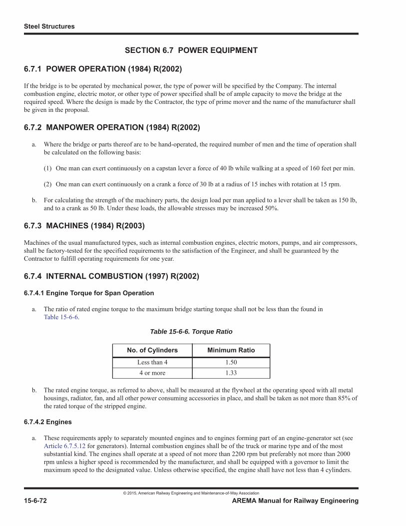
Steel Structures
© 2015, American Railway Engineering and Maintenance-of-Way Association
15-6-72 AREMA Manual for Railway Engineering
SECTION 6.7 POWER EQUIPMENT
6.7.1 POWER OPERATION (1984) R(2002)
If the bridge is to be operated by mechanical power, the type of power will be specified by the Company. The internal combustion engine, electric motor, or other type of power specified shall be of ample capacity to move the bridge at the required speed. Where the design is made by the Contractor, the type of prime mover and the name of the manufacturer shall be given in the proposal.
6.7.2 MANPOWER OPERATION (1984) R(2002)
a. Where the bridge or parts thereof are to be hand-operated, the required number of men and the time of operation shall be calculated on the following basis:
(1) One man can exert continuously on a capstan lever a force of 40 lb while walking at a speed of 160 feet per min.
(2) One man can exert continuously on a crank a force of 30 lb at a radius of 15 inches with rotation at 15 rpm.
b. For calculating the strength of the machinery parts, the design load per man applied to a lever shall be taken as 150 lb, and to a crank as 50 lb. Under these loads, the allowable stresses may be increased 50%.
6.7.3 MACHINES (1984) R(2003)
Machines of the usual manufactured types, such as internal combustion engines, electric motors, pumps, and air compressors, shall be factory-tested for the specified requirements to the satisfaction of the Engineer, and shall be guaranteed by the Contractor to fulfill operating requirements for one year.
6.7.4 INTERNAL COMBUSTION (1997) R(2002)
6.7.4.1 Engine Torque for Span Operation
a. The ratio of rated engine torque to the maximum bridge starting torque shall not be less than the found in Table 15-6-6.
b. The rated engine torque, as referred to above, shall be measured at the flywheel at the operating speed with all metal housings, radiator, fan, and all other power consuming accessories in place, and shall be taken as not more than 85% of the rated torque of the stripped engine.
6.7.4.2 Engines
a. These requirements apply to separately mounted engines and to engines forming part of an engine-generator set (see Article 6.7.5.12 for generators). Internal combustion engines shall be of the truck or marine type and of the most substantial kind. The engines shall operate at a speed of not more than 2200 rpm but preferably not more than 2000 rpm unless a higher speed is recommended by the manufacturer, and shall be equipped with a governor to limit the maximum speed to the designated value. Unless otherwise specified, the engine shall have not less than 4 cylinders.
Table 15-6-6. Torque Ratio
No. of Cylinders Minimum Ratio
Less than 4 1.504 or more 1.33

Movable Bridges
© 2015, American Railway Engineering and Maintenance-of-Way Association
AREMA Manual for Railway Engineering 15-6-73
1
3
4
The engines shall be tested by the manufacturer at his plant to demonstrate that they will develop the rated torque as defined in Article 6.7.4.1, where used for span operation.
b. The engine shall be equipped with reversing gears, preferably of the helical type, and preferably in a separate gear unit, having a gear ratio of not less than 2 to 1. Reversing shall be controlled by an approved friction clutch or clutches on the countershaft operated by a lever or other approved device. The machinery shall be operable in either direction without stopping the engine.
c. Engines having a rating of 20 hp or more shall be equipped with an electric starter with generator and storage battery. Where electric current is available at the bridge, a battery charging unit shall also be provided. Engines having a rating of 60 hp or less shall also be provided with a hand cranking device, where feasible.
d. Engines shall be cooled by means of a radiator and fan. A corrosion-resisting metallic exhaust pipe shall be provided, discharging outside the engine room and fitted with an effective muffler. Air inlets, including louvers, shall be arranged to ensure an adequate air supply to the engines.
e. The fuel tank shall be located outside the engine room, below the level of the intake. The tank shall be made of corrosion resisting metal and shall be large enough to hold fuel for 30 days of normal operation where the engine is used for span operation, and at least one day where used for standby service. The tank shall be protected from the sun. It shall be equipped with an automatic gage to show the quantity of fuel in the tank. The fuel pipe and fittings shall be of copper or brass, arranged and supported to provide for temperature and vibration movements tending to produce fracture and leakage. Protective fill and vent seal units shall be included to prevent accidental vapor ignition. A day tank, including pumps, shall be provided for engines over 60 hp. The installation shall be in accordance with the requirements of the National Fire Protection Association.
f. A small control board containing throttle and choke controls, ignition switch, starter button, and oil and temperature gages shall be provided at the engine, in addition to other controls that may be required for remote starting.
g. Where suitable, the ignition shall be of the jump-spark kind, so that a low voltage primary current of not more than 24 v will be sufficient for the secondary coil. For other fuel, the best device available shall be used.
h. The engine shall either be enclosed in a readily removable metal housing or located in a protected space, and, together with reversing gears and all other engine accessories, shall be mounted in the shop on a rigid steel frame so as to form a complete unit ready for installation.
i. The room containing span operating engines shall have indicators to show the position of the moving span and, if specified, of the lifting and locking apparatus.
j. Where low ambient temperatures may affect starting reliability, a water jacket heater or other suitable means shall be provided having such protective features as low oil pressure cut-out, high water temperature cut-out, and engine overspeed shut-down; and overcranking protection, if applicable.
6.7.5 ELECTRIC (1997) R(2003)
6.7.5.1 Basis of Specification Requirements
a. The specification requirements given herein are based on the use of either direct current or 60-Hz alternating current motors. Where specified, the bridge shall be operated by direct current motors using variable-voltage control or adjustable voltage control or with alternating current motors with control by semiconductor elements; in such cases the specification requirements shall be modified as specified by the Company.
b. For the operation of a vertical lift bridge, these requirements are based on the use of one hoisting machine to operate the bridge, or on the use of two hoisting machines mechanically connected. Provisions are also given for tower drive

Steel Structures
© 2015, American Railway Engineering and Maintenance-of-Way Association
15-6-74 AREMA Manual for Railway Engineering
vertical lift bridges using independent hoisting machines at the ends of the span operated by synchronized alternating-current motors. Where specified, such independent hoisting machines shall maintain the span in level position during operation by means of synchronizing controls; in such cases the specification requirements shall be modified as specified by the Company.
6.7.5.2 General Requirements for Electrical Installation
a. The Company will state the electric power service which is available and will give the location of the point at which such service shall be obtained. The Contractor shall provide the electrical installation complete from this service point, including all equipment, wiring, and cables, except as otherwise specified by the Company.
b. The electrical equipment shall conform to the standardization rules of IEEE and NEMA.
c. The NEC and local ordinances shall apply to the electrical material, construction, and installation, except as otherwise provided herein. In general, total voltage drops shall not exceed 5% at rated load for all electrical equipment.
d. Insofar as practicable, all major items of electric equipment shall be products of the same manufacturer in order to secure single responsibility and the most satisfactory service. All electrical equipment shall be equal to the best grade of that particular type of equipment made by the leading manufacturers.
e. The Contractor shall provide all grounds required for the electrical equipment and service.
f. In order to prevent deterioration due to corrosion of parts of the electrical installation other than electrical apparatus, allbolts, nuts, studs, pins, screws, terminals, springs, and similar fastenings and fittings shall be, where practicable, of an approved corrosion resisting material, such as brass, bronze or stainless steel, or of a material treated in an approved manner to render it adequately resistant to corrosion. Hot-dip galvanizing of materials in compliance with ASTM Specifications for such materials shall be considered such approved treatment. Corrosion preventive treatment of electrical apparatus shall be as specified by the Company to suit the conditions of exposure.
g. Except as otherwise approved by the Company, all metal parts of the electrical equipment, including all conduits not furnished with a fused coating of polyvinylchloride, shall be painted as specified for structural steel. For conduits and similar parts where it is not practicable or convenient to apply paint in the shop, the shop coat may be applied in the field, and followed by the required field coats.
h. The Contractor shall take insulation resistance readings on all circuits installed, with electronic equipment disconnected, and shall furnish a complete record of the results. These circuits shall preferably include connected motors when tested. Conductors rated 600 v or more shall be tested with a 500 volt instrument, and shall register at least one megohm. Defective circuits shall be replaced at the Contractor’s expense.
i. Provisions for emergency operation of power operated bridges, and for standby power for electrically operated bridges, shall be as specified in Article 6.2.5 and Article 6.2.6, respectively.
6.7.5.3 Working Drawings
a. In addition to furnishing the data required in Article 6.1.12, the Contractor shall provide complete working drawings for the electrical equipment. The tracings, or translucent copies thereof on cloth or polyester film, shall be corrected to show the work as constructed and shall then become the property of the Company. These drawings shall include the following:
(1) Wiring interconnection diagrams, giving termination identification of wires and cables, sizes and numbers of wires and cables, and the make and capacity of all apparatus, including the ratings of impedances. Schematic diagrams shall include three-line power diagrams showing the connection schemes including detailed apparatus and control schematic diagrams, which shall include the control panels and console. The number of each wire and designation for each electrical device or piece of apparatus shall be shown on the control schematic diagram. This device
Movable Bridges
© 2015, American Railway Engineering and Maintenance-of-Way Association
AREMA Manual for Railway Engineering 15-6-75
1
3
4
designation shall be used to identify each piece of apparatus on the assembly and installation drawings, which shall show locations to scale of all external and internal components including terminal blocks for the control panels, terminal boxes, and control console.
(2) Conduit drawings showing the routing and size of each conduit, the number and size of each wire therein, and the location and method of support of all conduits, ducts, boxes and expansion fittings. Each conduit shall be given an individual conduit designation.
(3) The requirements of paragraph (1) and paragraph (2) may be partially fulfilled by use of a suitably coordinated conduit and cable schedule.
(4) Installation drawings giving the location of all cables, conduits, control panels, control consoles, resistances, lamps, switches, and other apparatus.
(5) Sectional drawings of all cables showing component parts, their dimensions, and the material used.
(6) Drawings showing the general construction and dimensions of the control console and all control panels and the arrangement of all apparatus thereon.
(7) Certified dimension prints of all electrical apparatus.
(8) Detailed construction drawings of all boxes, troughs, ducts, and raceways other than conduit.
(9) Curves for each span driving motor showing the variation in motor speed and motor currents with output torque, and within the torque intervals determined by test (as specified in Article 6.7.5.4), for each power point on the controller.
b. Special apparatus shall be designated by the manufacturer’s name and catalog reference.
6.7.5.4 Motor and Generator Tests
a. One span driving motor of each size or type used shall be subjected to a complete test in accordance with the latest requirements of NEMA Standards for Motors and Generators. At the option of the Company, certified test data of a motor of identical design may be accepted in lieu of tests of the actual motors.
b. For alternating current motors the tests shall also include the determination of the variation in speed and motor currents with motor torques from zero to the maximum designed torque for the drive system. Where stipulated by the Company, the speed-current-torque curve shall also be determined for overhauling torque and including the effects of the motor control equipment. In addition, for wound rotor motors the speed-current-torque relationship shall be determined with a rotor shorted condition. At the option of the Company, some of these curves may be developed by computation.
c. Direct current motors shall also be tested to determine the speed-current-torque relationship for each power point on the controller, from an overhauling torque of 100% of full load to a driving torque of 200% of full load.
d. Unless otherwise specified by the Company, all other span driving motors shall be subjected to a short commercial test. Should the results indicate characteristics differing materially from those of the motor completely tested, the Contractor shall be required, at his own expense, to make the necessary alterations, and to run complete tests to demonstrate the final characteristics.
e. For tower drive vertical lift bridges with synchronizing motors, these motors shall be subject to the test requirements for span-driving motors; except that where the synchronizing motors are of the same size and type as the span-driving motors, only the short commercial test is required.
f. Each electric motor other than the span driving motors shall be subjected to a short commercial test.
Steel Structures
© 2015, American Railway Engineering and Maintenance-of-Way Association
15-6-76 AREMA Manual for Railway Engineering
g. Each generator shall be subjected to a short commercial test.
h. Except as otherwise approved by the Company, all motor and generator tests shall be made in the presence of the Company’s Inspector.
i. The Contractor shall furnish six certified copies of reports of motor tests and of all other required tests.
6.7.5.5 Motor Torque for Span Operation
a. The required locked rotor and breakdown torques for a-c motors shall be those specified by NEMA.
b. Motor torques shall be as follows:
(1) One-motor installation. The rated full load motor torque shall be not less than 80% of the maximum bridge starting torque, and the maximum torque peaks that occur when the bridge is accelerated to the required speed, using the specified bridge control, shall preferably not exceed 180% of the rated full load motor torque.
(2) Two-motor installation with no provision for operating of the bridge with a single motor. The two motors jointly shall meet the requirements given in paragraph a for one motor.
(3) Two-motor installation with provision for operating the bridge with a single motor in not more than 1.5 times the opening times specified in Article 6.3.6.
c. Where specified or approved by the Company, the power requirements of motors may be less than specified in Article 6.3.6.
d. The maximum bridge-starting torque shall be determined in accordance with the requirements of Article 6.3.6.
6.7.5.6 Number of Motors
a. Where the total power necessary at the motor shaft to move the bridge according to Article 6.3.6a(1) at the required speed exceeds 50 hp, the use of two similar span driving motors, with provision for operation of the bridge by one motor shall be considered.
b. Except as otherwise specified by the Company, the rail locks, the span locks, and the end and center wedges of swing spans, shall be operated by one or more motors separate from and independent of the span-driving motors.
6.7.5.7 Synchronizing Motors for Tower Drive Vertical Lift Bridges
Where synchronizing motors are used on tower drive vertical lift bridges to maintain the bridge in level position during operation, the total full load rated torque of these motors on each tower shall not be less than 50% of the total full load ratedtorque of the span driving motors on each tower.
6.7.5.8 Speed of Motors
The speed of span driving motors shall not exceed 900 rpm. The speed of integral horsepower motors that operate rail locks, bridge locks and wedges shall not exceed 1,200 rpm. The speed of gear motors of 10 hp or less, fractional horsepower motors, and motor generator sets shall not exceed 1,800 rpm.
6.7.5.9 Motors – General Requirements
a. Motors shall be of the totally enclosed crane, hoist or mill type, except where the size specified cannot be obtained, or unless authorized by the Company. Motors shall be as nearly waterproof as practicable. Motors subjected to atmospheric conditions shall be totally enclosed and waterproof; and non-ventilated if subjected to reduced-speed duty. Motors installed in weather-protected houses may be either drip proof or protected type. Unless otherwise specified by the Company, motor windings shall be impregnated with a moisture resisting compound to increase the resistance to
Movable Bridges
© 2015, American Railway Engineering and Maintenance-of-Way Association
AREMA Manual for Railway Engineering 15-6-77
1
3
4
excessive moisture, and span drive motors shall have embedded winding temperature sensitive devices. A drain hole shall be provided in the bottom of the motor frame and, where feasible, heaters shall be built in. Motors whose frames tilt during the operation of the bridge shall have ball or roller bearings arranged with provisions for flushing. Span motors shall be capable of stalled operation for two minutes with the motor control equipment functioning normally for seating torque. Primary and secondary conduit boxes for span drive motors shall be split cast and fully gasketed, with a lead bushing and a threaded conduit hole sized 2 inches or more in diameter.
b. Direct current motors shall be series, compound, or shunt wound, as determined by the performance specified, and shall have commutating poles. Motors to be used for dynamic or regenerative braking shall perform that function without injurious sparking or temperature rise. Span driving motors shall conform to the requirements of AISE standards for mill motors.
c. Alternating current motors shall be induction motors, suitable for the service characteristics specified, and conforming to the requirements of NEMA. Span driving motors shall be of the wound rotor crane type when AC variable voltage control or secondary resistance control is utilized. All other motors shall be of the squirrel cage type.
6.7.5.10 Heating Requirements for Motors
a. All alternating current span driving motors and motors used directly or indirectly in conjunction with the span driving motors shall be capable of delivering their rated output continuously for at least 30 min. without exceeding 80 degrees C rise in temperature for Class B insulation measured by resistance, or 70 degrees C rise if specified by the Company.
b. All direct current motors shall be capable of delivering their rated output continuously for at least 30 min without exceeding 80 degrees C rise in temperature measured by resistance, or 70 degrees C rise if specified by the Company.
c. Motors other than span driving motors shall be rated on the basis of 15 minutes, provided that their running time during a single opening of the bridge does not exceed 30 seconds.
d. Where the maximum one hour ambient temperature exceeds 40 degrees C, the temperature rise requirements of this Article shall be adjusted accordingly.
6.7.5.11 Gear Motors
Gear motors shall preferably be provided with an extension of the high speed shaft to allow hand operation. Electrical operation of the gear motor shall be prevented by a suitably wired limit switch when the hand crank is inserted. Gears shall belubricated by immersion in the lubricant, and effective seals shall be provided to prevent the lubricant from reaching the motorwindings. Gear motors shall have not less than a Class II rating as defined by the AGMA and shall carry an AGMA nameplate stating the horsepower, service rating and service factor.
6.7.5.12 Engine-generators
a. Engine-generators sets, either for primary or emergency power, shall consist of an internal combustion engine and an electric generator, direct connected and mounted on a common base. Separate units may be provided for supplying power for span operation and for auxiliary services such as lights and signals. Where used as emergency power source, the lighting generator unit shall start automatically and transfer the load automatically upon failure of the normal power. The span operating power unit shall be started manually by a remote control switch.
b. Engines shall, in general, conform to the applicable requirements of Article 6.7.4.2 with additional controls as specified in paragraph c. The engines shall develop adequate power to supply the maximum load, including motor starting load, while maintaining speed within the specified range.
c. Engine instruments and controls shall be mounted in a cabinet on the unit and shall include gages indicating water temperature, oil pressure and temperature, vacuum for diesel engines, throttle control, start/stop switch for manual control, manual emergency shut-down and indicating lights for low oil pressure, high water temperature, overspeed
Steel Structures
© 2015, American Railway Engineering and Maintenance-of-Way Association
15-6-78 AREMA Manual for Railway Engineering
and overcrank, and an alarm contact for sounding a remote alarm in case of high water temperature, low lubricating oil pressure or failure to start after four cranking cycles.
d. Engine governor shall be of the centrifugal type providing 3% to 5% regulation from no load to maximum load.
e. The generator shall be capable of supplying the maximum load, including motor starting load, with regulated voltage drop within limits specified. It shall have a continuous rating of 70 degrees C rise in temperature for Class B insulation over 40 degrees C ambient, shall have drip-proof construction, and shall conform to ANSI and IEEE standards.
f. The exciter shall be the direct connected, brushless type sized to furnish 10% excess excitation required at full generator operating load.
g. The generator control panel shall be suitable for wall mounting and shall contain the following devices: Three-position control switch “Off-Auto-Manual” for automatic starting units; air circuit breaker; Voltmeter, Ammeter, and their switches; Frequency Meter; Elapsed time meter; Automatic voltage regulator, Voltage adjustment rheostat; alarm contacts for remote indication; and automatic starting device when in “Auto” position for automatic power transfer switch, if required.
6.7.5.13 Automatic Electric Power Transfer
a. Where two sources of electric power are available, power for continuous services, such as lights, and navigation signals, shall be transferred automatically from the normal feeder to the standby or emergency source upon failure of the normal supply. Upon return of the normal power to at least 90% of rated voltage, the load shall be retransferred after an adjustable time delay of not less than five minutes. Should the emergency source fail, the retransfer shall be instantaneous upon return of normal power. The automatic transfer switch shall be electrically operated and mechanically held, with a single solenoid or motor mechanism and separate arcing contacts, and shall be enclosed in a wall-mounted cabinet, with circuit diagram on inside of door.
b. Where both power sources are external, one designated “Normal,” the other “Stand-by,” an auxiliary switch shall be provided to permit using either of the two as the preference source.
c. Where the standby source is an engine-generator set, the automatic transfer switch shall be equipped with a pilot contact for remote automatic starting of the engine 3 sec after normal source failure or after drop of any phase to 70% or less of the rated voltage. The normal load circuits should remain connected during this 3 sec delay. When the standby generator delivers not less than 90% rated voltage and frequency, the load shall be automatically transferred. After transfer, the engine shall run five min and then automatically shut down. The transfer switch shall have a test button so that normal source failure can be simulated.
6.7.5.14 Electrically Operated Motor Brakes
a. “Motor” brakes (Article 6.3.9) for the span driving motors, shall be base mounted shoe brakes which are held in the set position by springs with such force as to provide the required retarding torques (Article 6.3.9). Brake wheels for the motor brakes shall be mounted on the motor pinion shaft, or on a motor shaft extension.
b. Brakes shall be designed for intermittent duty for the required retarding torques. The brakes shall be designed to release when the current is on, and to apply automatically when the current is cut off. Brakes for the span operation shall be provided with hydraulic, mechanical or electrical escapements, such that the brakes will not be applied at the same time.
c. The brakes shall be equipped with a means for adjusting the torque and shall be set in the shop for the specified torque. Each brake shall be provided with a nameplate which shall state the torque rating of the brake, and the actual torque setting where it differs from the torque rating. Shoe type brakes shall be so designed that it is possible to adjust the brakes or replace the shoe linings without changing the torque settings.
Movable Bridges
© 2015, American Railway Engineering and Maintenance-of-Way Association
AREMA Manual for Railway Engineering 15-6-79
1
3
4
d. Direct current brakes shall be released by thruster units or shunt-coil solenoids. Shunt coils shall have discharge resistors or surge suppressors so that opening the shunt-coil circuit does not cause high transient voltage.
e. Alternating current brakes shall be released by thruster units, or motor operators if so specified. Thruster motors exposed to the atmosphere shall be totally enclosed and non- ventilated with weatherproof insulation of both the motor and conduit box.
f. For shoe type brakes the releasing mechanism shall be capable of exerting a force of not less than 130% of the force actually required to release the brake when set at the specified torque setting and at the minimum expected ambient temperature.
g. Brakes for other motors shall be solenoid released shoe type brakes or dry type disk brakes, and shall have an intermittent rating not less than the full load torque of the motors.
h. Brakes shall be of a construction which ensures uniform wear, and shall have independent provisions for adjusting lining wear, equalizing clearance between friction surfaces, and adjusting the retarding torque. The brake linings shall not be affected by moisture. Solenoids, thruster units, and motor operators shall be moisture proof. Fittings shall be corrosion resisting. Thrusters for shoe type brakes shall be provided with year around oil.
i. Shoe type brakes shall be provided with a permanent manual release lever suitable for one man operation. Means shall be provided for latching the lever in the set and released positions. Disk type brakes shall be provided with a manual release which can be latched in the released position; the manual release shall automatically reset when the brake is energized.
j. Where brakes are located outside the machinery house, they shall be of weatherproof construction or shall be provided with a weatherproof housing. The housing shall be arranged to permit operation of the hand release lever from outside the housing.
k. Brakes installed on the moving span, shall operate satisfactorily with the span in any position.
l. Where specified by the Company, brakes shall be provided with heating elements to prevent the accumulation of moisture and frost, and shall have provision for the addition of limit switches for control, and of lights to indicate the position of the brakes and their hand release levers.
6.7.5.15 Electrically Operated Machinery Brakes
a. Machinery brakes (Article 6.3.9) for the span-operating machinery shall meet the requirements for the “motor” brakes, except as otherwise herein provided.
b. Brake wheels shall be shipped to the manufacturer of the machinery who shall press them onto the shafts.
6.7.5.16 Design of Electrical Parts
a. For lift bridges electrical parts, including wiring, switches, circuit breakers, controllers, and contactors, shall be designed for operation of the bridge using either normal or emergency power for the span loads (as specified in Article 6.3.6) and for the operating cycles and durations (as specified in Article 6.9.10). For bascule and swing bridges these parts shall be similarly designed for bridge operation for the specified span loads (Article 6.3.6) and for 30-minutes continuous operating cycles of Condition B load for bascule bridges and 30-minutes continuous operating cycles of Condition A load for swing bridges.
b. The temperature rise of electrical parts under such operation shall not exceed that for which the part is normally rated including those of Article 6.7.5.10 and Article 6.7.5.38.

Steel Structures
© 2015, American Railway Engineering and Maintenance-of-Way Association
15-6-80 AREMA Manual for Railway Engineering
6.7.5.17 Electrical Control
a. Methods of span electrical control may be classified as either “Master Switch Control” and “Automatic Sequenced Control.” Except for these differences, the following general features shall apply:
(1) Separate controllers shall be provided for the span driving motors, the rail lock motors, the span lock motors and the wedge motors.
(2) Where there are two main direct current motors powering one output, the control shall be series, parallel, or series parallel as required, except that where the current is furnished by a storage battery, the control shall be of the series parallel type.
b. The following features shall apply to master switch control:
(1) Where each span driving motor is rated at more than 75 HP, the control shall be of the full magnetic type. Where the rated horsepower of each span driving motor rated at is 75 HP or less, the control shall be of the full magnetic, or semi-magnetic type, as stipulated by the Company.
(2) For full magnetic control, all span driving and span brake circuits shall be energized by magnetic contactors opened and closed by control circuits wired through and operated by the master switch. Speed of span shall be controlled by accelerating contactors.
(3) Semi-magnetic controls shall be as specified for full magnetic controls except that the speed of span operation shall be controlled in whole or in part by opening and closing the motor circuits directly by means of the master switch.
(4) Motor brakes shall be controlled through contacts on the master switches so arranged that all motor brakes shall be held released when power is applied to the span driving motors.
(5) Where two motor brakes are used on a hoisting machine, a control point for each motor brake shall be provided for each direction of travel so that the motor brakes may be applied separately.
(6) For tower drive vertical lift bridges, two points of motor brake control shall be provided for each direction of travel where two motor brakes are used for the hoisting machine in each tower.
(7) Electrically operated machinery brakes may be controlled either through contacts on the master switch, or by a separate switch.
(8) Where the machinery brakes are controlled by the master switch, the contacts shall be so arranged that all machinery brakes are held released when power is applied to the span driving motors, except when the seating switch is used, as hereinafter described. The sequence of the master switch contacts shall be so arranged that the machinery brakes may be applied by the operator whenever the span is coasting. One point of machinery brake control shall be provided for each direction of travel for all machinery brakes on a hoisting machine.
(9) Where the machinery brakes are controlled by a separate switch, they shall normally be set, and shall be so arranged, that they must be released by the operator before starting the bridge. They shall be held in release during the entire operation unless the operator desires to use them while coasting, or unless an emergency condition arises requiring brake power in excess of that offered by the motor brakes, when they may be applied instantly by the operator. This portion of the equipment shall be designed so that it will not be injured if left in release indefinitely. Where so specified, the brakes shall be provided with not less than three steps of retarding torque to permit partial application of the brakes. The machinery brake circuits shall be independent of the general interlocking system, and may be an electrically operated interlocking device which will prevent the use of the span driving motors and the machinery brakes one against the other, except by the use of the seating switch hereinafter described.
Movable Bridges
© 2015, American Railway Engineering and Maintenance-of-Way Association
AREMA Manual for Railway Engineering 15-6-81
1
3
4
(10) A seating switch shall be provided for applying the machinery brakes while power is still on the motors, in order that the span may be drawn tightly to its seat and held in that position. The seating switch shall be convenient to the operator and shall be hand or foot operated.
(11) For tower drive vertical lift bridges, one control point for each direction of travel shall be provided for all machinery brakes. In addition, all machinery brakes shall be applied automatically if the span should exceed a predetermined skew.
(12) Motors for rail locks, span locks, wedges, and other devices associated with the movement of the span shall be controlled through magnetic contactors energized by control switches independent of the master switch.
c. The following features pertaining primarily to span operation shall apply to automatic sequenced control:
(1) The normally required action by the operator consists of the initiation, by one movement of a single pushbutton or hand lever, each of the several major interlocked functions in sequence. Examples of sequenced steps include:
• actuate railroad signals.
• pull rail locks.
• pull span locks.
• raise span.
(2) Emergency actions by the operator could include operation of bypass switches, selection of emergency mode of span operation, and skew correction following skew limit switch operation.
(3) Span motor controls shall include all components required to protect the motor against abnormal conditions, automatically controlled acceleration and deceleration, modulated speed control where applicable (such as for tower drives without power synchronizing motors), adequate controlled speed regulation to accommodate overhauling loads (negative torque or regenerative braking loads), and other features as required to ensure satisfactory performance following a single movement of the initiating control switch.
(4) Selection of motor and machinery brake types, and control arrangements shall ensure time sequenced brake application under all conditions.
(5) Two modes of stopping span movement shall be provided:
(a) normal stop, with controlled electrical deceleration followed by brake application, and
(b) emergency stop, with immediate power cutoff and application of brakes, initiated by an emergency stop button.
(6) Limit switch actions shall initiate deceleration prior to the “nearly open” and “nearly closed” span positions. The control system shall be designed to accomplish reduction to slow speed when those positions are passed. Speed limit switches shall be provided to detect span speed at the “nearly open” and “nearly closed” positions. Where span speed is within the normal limit of the span, movement shall continue to completion; where not, power shall be cut off and brakes applied, and a reset operation of the overspeed circuit shall be required before span movement can be resumed.
(7) During final seating, the motor torque shall be reduced and the brakes shall remain in released position until the span is tightly seated, after which the brakes shall set and the motors disconnected.

Steel Structures
© 2015, American Railway Engineering and Maintenance-of-Way Association
15-6-82 AREMA Manual for Railway Engineering
(8) Tower drive lift bridges arranged for automatic sequenced control shall have two independent skew limit switches, in effect for each span mode of operation, connected in series.
(9) As specified by the Company, the drive system may include alternating current or direct current motors controlled by semiconductor devices.
6.7.5.18 Speed Control for Span Driving Motors
a. Master switch control for span driving motors shall provide for speed control. In general, not less than six steps of acceleration shall be provided, such that the motor torque will differ as little as practicable from the average torque required for uniform acceleration from zero speed to full speed. The acceleration steps shall be such that the bridge will start slowly and will accelerate and decelerate smoothly and without excess torque when under the smoothest friction conditions and without wind or other unbalanced load; and such that the bridge will accelerate and decelerate similarly when the motors are carrying their maximum loads. Separate resistors shall be provided for each motor.
b. Solid state variable speed drives for control of AC or DC span driving motors shall provide for smooth, stepless speed control over a speed range of at least 10 to 1. Speed regulation shall be 2 percent or better up to rated motor speed. A closed-loop feedback type speed control system with overspeed detection shall be used. Speed and torque control shall be four-quadrant regenerative, with static (contactorless) reversing. Dynamic braking may be utilized as a supplement to regeneration, but shall not be the primary means of controlling overhauling loads. Acceleration and deceleration ramping shall be field adjustable from 2 to 20 seconds. A minimum of two adjustable speed settings shall be provided, one covering a range of approximately 50% to 100%, and one covering a range of approximately 5% to 25% of rated speed. Two independent adjustable settings of torque limiting shall be provided, each covering the minimum range of 50% to 150% rated motor full load torque. Automatic drive shutdown with fault indication, shall be provided for loss of feedback signal. Each variable speed drive shall be provided with a disconnect circuit breaker and an isolation contactor mounted in the drive cabinet to remove power from the solid state switching components and/or the connected motors when the span driving motors are not being operated. The solid state speed control shall be a standard product of the manufacturer. For two motor installations, drives shall be arranged to provide equal torque from each of the motors.
6.7.5.19 Magnetic Control For Span Driving Motors
a. The following features shall apply to full magnetic control with master switch:
(1) Master switches
Master switches for the span driving motors shall be cam operated reversing switches with a single handle, and provided with necessary contacts and contact fingers for operating the magnetic contactors. Contacts and wearing parts shall be easily removable and replaceable. The controller shall provide for speed control of the motors.
(2) Parallel or series-parallel operation
For parallel operation for alternating current motors, and for constant potential parallel or series-parallel operation for direct current motors, there shall be separate reversing contactors and separate resistors for each motor. Where two motors are connected to one hoisting machine, accelerating contactors shall be common to both motors, unless otherwise specified by the Company. For three-phase alternating current motors, each phase shall have its own resistors, so designed as to give balanced current in all three phases. Certain of the acceleration contactors shall be controlled by acceleration relays, such that the specified torques in Article 6.7.5.5 are not exceeded. Where common accelerating contactors are not used, the acceleration contactors shall be so designed, or electrically or mechanically connected, that corresponding circuits in each motor control will be made simultaneously, and that in the event one motor is cut out, the control for the motor in service will operate satisfactorily.
(3) Acceleration relays

Movable Bridges
© 2015, American Railway Engineering and Maintenance-of-Way Association
AREMA Manual for Railway Engineering 15-6-83
1
3
4
Adjusting plugs, screws, and nuts, including time limit adjustments, shall be easily accessible to allow for adjustment of relays to the proper timing intervals between acceleration steps. The contacts shall be removable without disturbing the setting of the relays.
(4) Reversing of motors
Magnetic shunt type contactors for reversing the motors shall be installed with a forward and a reverse pole for each motor conductor.
b. The following features shall apply to semi-magnetic control:
(1) For semi-magnetic control, a drum type master switch shall be provided for reversing the motors by contactors controlled by contacts on the master switch. The master switch accelerating contacts shall carry the secondary current at the step applied without exceeding a 30° C temperature rise, and when the motors are operating a full load torque, or at stalled torque if it is less. Reversing contactors, and accelerating contactors used in conjunction with the accelerating contacts of the master switch, shall meet the requirements of Article 6.7.5.27.
(2) For control of motors in parallel the switches shall be interconnected so that all switches will be operated simultaneously by one handle. The controllers shall be so arranged that the operation of one motor may be cut out without affecting the operation of any other motor.
6.7.5.20 Programmable Logic Controllers
a. Programmable logic controllers (PLC) may be used for the sequential control and continuous monitoring of bridge operations. The PLC’s shall be manufactured and tested in accordance with applicable IEEE and NEMA standards. The PLC’s shall be installed and grounded in accordance with the manufacturer’s recommendations and the requirements of NEC.
b. The following features shall apply to bridge control with programmable logic controllers:
(1) Cold Backup PLC.
Cold backup shall generally be the preferred backup method. For cold backup, two identical PLC’s (CPU’s only) shall be provided, and shall be wired in place. One PLC shall normally be de-energized and electrically isolated from power source and input/output (I/O) racks via transfer switches or relays until selected for operation. Separate, dedicated power supplies shall be provided for each PLC. Common I/O modules and racks shall be shared by both PLC’s, but only electrically connected to the active one.
(2) Hot Backup PLC.
In certain situations, where momentary interruption to the PLC system cannot be tolerated, hot backup may be utilized. For hot backup, two identical PLC’s shall be connected so as to be operating simultaneously, with PLC processor error and fault checking, memory and register updating.
(3) Power Conditioning.
All PLC’s and I/O racks shall be protected against power source surge and noise problems by the use of a power conditioning system, including surge suppression, in the power line ahead of all power supplies and ahead of all power connections to I/O modules and any other devices, connected to the PLC’s. Consideration shall also be given to the use of surge suppression terminal blocks for all conductors connecting to PLC inputs.
(4) System De-energizing.

Steel Structures
© 2015, American Railway Engineering and Maintenance-of-Way Association
15-6-84 AREMA Manual for Railway Engineering
The PLC system shall be provided with a master control power switch on the control console which directly interrupts all power feeds to I/O modules when control power is turned off. A standby mode may be utilized with such switch in which input modules remain energized.
(5) Emergency Stop.
A maintained-contact Emergency Stop pushbutton shall be provided which interrupts the PLC logic sequence, and simultaneously and immediately directly interrupts all output module power feeds associated with all bridge operating machinery and all other bridge-related moving equipment including roadway gates and barriers if present.
c. A PLC programming terminal shall be furnished with each PLC system. The PLC programming terminal shall be a compact, portable computer with all necessary PLC programming software, hardware, and communications link cables and adapters specific to the PLC installed. All software registrations and product warranties shall be in the Company’s name.
6.7.5.21 Resistances and Reactors
a. Resistors for motor control shall, unless otherwise specified, be non-breakable, corrosion resistant, edgewise wound or punched grid resistor units. The resistors for the span operating motors, unless otherwise specified, shall be of a capacity equal to NEMA intermittent cycle rating providing for 15 sec on out of each 45 sec. The resistors shall be mounted on a steel frame so as to be free from injurious vibration and to permit free circulation of air; and shall be furnished so that any unit or part of a unit may be removed and replaced without disturbing the others. The units shall be insulated from their supports.
b. For wound rotor motors with secondary resistance control, the controller shall be so arranged that a small amount of resistance shall always be left in the rotor circuits of each motor. This permanent resistance section shall be adjustable after installation, and shall be proportioned for continuous duty.
c. Reactors for secondary control of wound rotor motors shall be arranged to present the same reactance to each motor phase, and they shall be mounted so as to be free from injurious vibration, to permit free circulation of cooling air, and to be protected from any dripping liquids.
6.7.5.22 Switches for Limiting Travel and Speed
a. Limit switches which will stop the motors and set the brakes automatically at the end of travel shall be provided for the span lock, rail lock, end wedge and wedge motors. The term limit switch includes all types of mechanical switches as well as encoders, resolvers and proximity switches.
b. Limit switches shall be provided for the movable span with master switch control which will cut off the current from the span driving motors and set the brakes so as to stop the span in the “nearly closed” and “nearly open” positions. It shall then be necessary to return the controller handle to the “off” position to bypass the limit switch contacts and regain control of the span to fully close or fully open the bridge. Where specified, relays shall be provided which will prevent the bypass from functioning until a predetermined time after the brakes have set. Additional limit switch contacts shall be provided to stop the span in the “fully open” position, and for swing bridges, where specified, in the “fully closed” position. Unless otherwise specified, the “nearly closed” and “nearly open” positions shall be taken to be 6 feet from the “fully closed” and “fully open” positions, respectively.
c. Fully seated switches shall be provided for vertical lift and bascule bridges which shall indicate to the operator when the bridge is fully closed.
d. “Skew” limit switches mechanically connected to the machinery on the two towers, or equally effective devices of other type, shall be provided for tower drive vertical lift bridges which will cut off the current from the main motors and set the brakes so as to stop the span whenever it is more than a prescribed amount out of level.
Movable Bridges
© 2015, American Railway Engineering and Maintenance-of-Way Association
AREMA Manual for Railway Engineering 15-6-85
1
3
4
e. Limit switches exposed to the weather shall be watertight and all exposed parts shall be corrosion resisting. Where plunger type limit switches are used for fully seated switches, they shall be weatherproof and shall be provided with cast or malleable iron enclosures and stainless steel operating rods.
f. Electrically operated bridges, shall include an over-speed limit switch to stop the span whenever normal span speed is exceeded by 10 percent or more.
6.7.5.23 Interlocking
a. The operating mechanisms of all movable bridges shall be so interlocked that the operation of all devices can be performed only in the prescribed sequence.
b. Emergency bypass switches shall be provided which will free the various motors from the prescribed interlocking in case of emergency. These switches shall be conveniently mounted on the control desk or on the main switchboard. Each such emergency switch shall be sealed in the “off” position.
c. Auxiliary power units and main power units shall be interlocked to make each one inoperative while the other is in service.
d. Motor and machinery brakes shall be provided with limit switches so arranged that the bridge shall be inoperable whenever any brake or combination of brakes shall be released by hand, such that the available braking torque left in service would be insufficient to meet the requirements in Article 6.3.9.
e. Motors equipped with a shaft extension for hand operation shall be provided with a suitably wired limit switch to prevent electrical operation of the motors when the hand crank is inserted.
6.7.5.24 Switches
a. An enclosed switch or circuit breaker shall be provided as a disconnect for the supply feeder, with a pole for each ungrounded conductor. A similar switch, or a circuit breaker capable of being operated as a switch, shall be provided as a disconnect for each motor, light, signal or other circuit.
b. Main disconnect switches shall not be less than 60 amp capacity.
c. Toggle and tumbler switches shall be of corrosion resistant construction and they shall not be less than 20 amp capacity.
6.7.5.25 Circuit Breakers and Fuses
a. An automatic circuit breaker shall be placed in the supply line and be arranged with undervoltage release or trip coils to permit provision of undervoltage, reversal, and loss of phase protection. Where the supply has very large short circuit capability, suitably rated current limiting fuses may be provided in a disconnect switch ahead of the automatic circuit breaker, or otherwise incorporated into its design to accomplish alternate suitability. Where practicable, circuit breakers shall be used to provide short circuit protection for all wiring circuits. Molded case circuit breaker selection shall include a comparison of either the short circuit interrupting ability of the I2t rating (the integral of the square of the short circuit current, I, with respect to time, t, for the period of interrupting time duration), with the respective shortcircuit capacity of the I2t rating of the supply source connection. They shall not be applied to circuits with possible short circuit duty in excess of 60% of their rated interrupting ability or, if preceded by current limiting fuses, their permissible I2t source rating shall be at least 125% of the rated I2t let-through of the preceding fuses for the particular application. Such a protective device shall be provided in each motor, brake, light, signal, indicator or other circuit. Where fuses are used, they shall generally be of the dual element or current limiting type.
b. All circuit breakers shall be air break type for 600 v and less. For circuits above 600 v, either air break, vacuum break, or oil immersed circuit breakers shall be used as required by the service conditions. Breakers shall have a pole for each
Steel Structures
© 2015, American Railway Engineering and Maintenance-of-Way Association
15-6-86 AREMA Manual for Railway Engineering
phase wire feeding through the breaker, an overload device consisting of a thermal or magnetic element for each pole, and a common trip.
c. Circuit breakers shall not be used for motor overload protection or for limiting the travel of any mechanism.
6.7.5.26 Contact Areas
For custom designed electrical equipment such as slip rings for swing bridges, line contacts shall be avoided where practicable. The current per square inch of contact area shall not exceed 50 amp for spring held contact, or 100 amp for boltedor clamped contact.
6.7.5.27 Magnetic Contactors
Magnetic contactors shall have an 8 hr rating not less than the current through the contactor when the connected apparatus is operating at rated load. Magnetic contactors shall be of the shunt type, and shall be quick acting. Contacts shall be well shielded to prevent arcing between them and other metal parts near and shall be designed so as to be readily accessible for inspection and repair. Copper contacts shall have a wipe. Contactors shall have double-break features or shall have magnetic blowouts or equivalent means for rapidly quenching the arc and shall have a minimum number of parts, and all steel parts shall be corrosion resistant. Magnetic motor starters shall have no less than 25 amp rating.
6.7.5.28 Overload Relays
a. Overload relays, automatic or hand reset as specified, shall be used in each phase or d-c circuit for overload protection of all motors.
b. Instantaneous magnetic overcurrent relays shall also be provided in motor circuits to de-energize all motors when the safe torque is exceeded, unless other means are provided for limiting the maximum torque.
6.7.5.29 Shunt Coils
Where shunt coils are used, in particular with brakes and magnetic contactors, the insulation shall be capable of withstanding the induced voltage caused by cutting off the current.
6.7.5.30 Instruments
A line voltmeter, ammeters for span driving motors, and a power bus wattmeter, shall be provided and mounted on the control console. A voltmeter switch shall be provided for measuring the voltage between any two phases and between any phase and ground. Instruments shall be of the rectangular illuminated type, and flush mounted and back connected.
6.7.5.31 Protection of Apparatus
Electrical apparatus shall be protected from the weather and from accumulations of dirt.
6.7.5.32 Cast Iron in Electrical Parts
Where cast iron is used in switches and small electrical parts, it shall be of the malleable type.
6.7.5.33 Position Indicators
Synchronous moving span position indicators of the high accuracy type guaranteed within ± 1 degree shall be provided. Transmitters shall be geared to trunnion shafts, counterweight sheave shafts, or machinery shafts, whichever is most suitable for the particular installation, and the receivers in the control console shall be geared to the indicators. Gearing shall be arranged so as to give the greatest practicable accuracy.
Movable Bridges
© 2015, American Railway Engineering and Maintenance-of-Way Association
AREMA Manual for Railway Engineering 15-6-87
1
3
4
6.7.5.34 Indicating Lights
a. Indicating lights of suitable colors shall be furnished and installed on the control console to show span positions, especially the fully closed, fully open, nearly closed, and nearly open positions, and also the positions of the span locks, rail locks, and end wedges. Indicating lights shall also be provided to show the released position of each span brake, the overload or overheat tripping of span drive motors, and the status of other emergency functions.
b. Where specified, indicating lights may be oil-tight “push-to-test” type.
6.7.5.35 Control Console
a. The span control console shall contain switches for the span operating motors and for the lock, end lift and wedge motors; seating switches; bypass switches, instruments; position indicators; indicating lights; and all other control devices and apparatus necessary or pertinent to the proper operation and control of the span and its auxiliaries by the operator.
b. The control console shall be located so as to afford the operator a clear view in all directions. The console shall be of cabinet type construction with a horizontal front section about 36 inches above the floor and an inclined rear instrument panel set at such a slope that the meters can be read from average eye level without parallax and without reflection from the glass instrument cover. The console plan dimensions and the arrangement of equipment shall be such that all control devices are within easy reach. The top of the console shall be a laminated phenolic compound not less than 1 inch thick, with edges beveled and neatly finished. Where specified by the Company, the top of the console may be of No. 10 U.S. Standard gage stainless steel with a non-reflecting finish. The horizontal and sloping sections of the top shall be accurately cut to ensure a close fit.
c. The console frame shall be constructed of sheet steel of not less than No. 11 U.S. Standard gage. All corners and edges of the console shall be rounded, and the sheet steel shall be reinforced by flanging the metal into angle and channel sections. Connecting sections shall be properly joined by either continuous seam welding or spot welding to provide a rigid free-standing structure. Outside surfaces shall be smooth and without visible joints, seams or laps. The bottom of the console shall be left open. The supporting flange on the inside of the console frame at the bottom shall be provided with suitable holes for bolting the console to the floor. Suitable brackets and angles shall be provided on the inside of the console to support the top and the equipment mounted thereon.
d. The control console shall be provided with hinged doors on the front, and with doors, removable panels, or fixed panels on the back and sides, as specified by the Company, to suit the requirements of the installation. Doors shall have well-rounded flanged edges, and shall be flush mounted on concealed hinges, and shall incorporate jambs to limit the swing. Doors shall be fitted with sturdy, three point latches operated by flush type, chromium plated handles, and shall be assembled accurately and shall have a clearance not exceeding 1/8 inch at any point.
e. The “off” position of master switch handles shall be toward the front of the console. For bascule and swing bridges, the direction of rotation of each master switch shall be such that when it is moved from the “off” position, the span, as seen by the operator, will move in the same direction as the master switch handle. For double leaf bascule bridges, the switches shall rotate opposite. For vertical lift bridges, clockwise rotation shall raise the bridge.
f. Seating switches, where foot-operated, may be supported by the outside of the console or may be set in a suitable recess at the bottom of the console. Foot recess shall be rounded at the top to a l-1/4 inch radius.
g. Outgoing control connections from the console shall be brought to suitably marked barrier type terminal boards supported on straps securely attached to the console frame. Terminal boards shall be located so that they do not interfere with door access to the inside of the console. Wires shall be copper and shall be brought from the terminal boards to their respective terminals in a neat and orderly arrangement, properly bunched and tied.

Steel Structures
© 2015, American Railway Engineering and Maintenance-of-Way Association
15-6-88 AREMA Manual for Railway Engineering
h. The console when finished shall be given one coat of moisture-resisting primer and one coat of filler on all surfaces. The outside surfaces shall be given a finished coat of dull lacquer of a color specified by the Company. The horizontal console top shall not be painted.
i. The console interior shall be equipped with suitable lights controlled from a switch on the console.
j. Each piece of equipment and each indicating light on the control console shall have a properly engraved metal or lamicoid nameplate showing white characters on a black background or black characters on a white background. The designation on the nameplates shall correspond with that shown on the wiring diagrams.
6.7.5.36 Control Panels
a. Control panels shall be of enclosed, dead front, free standing construction, NEMA Type 1 or better. All disconnect switches, circuit breakers, contactors, relays, rectifiers, instrument transformers, and other electrical equipment for the control of the span and its auxiliaries shall be mounted on or in the control panels.
b. The control panels shall be constructed of sheet steel of not less than No. 11 U.S. Standard gage, generally as described in Article 6.7.5.35 for the control console. Equipment mounted at the bottom of the panel boards shall clear the floor by at least 6 inches. Except for front connected or wall mounted panels, there shall be a distance of at least 2-1/2 feet between the wall and the back of the panelboard. Open control panels, where specified, shall be installed in a separate room provided with a lockable door.
c. Control panels shall be designed and installed with a view to the safety of the operator. The equipment shall be so arranged as to be easily reached and operated and to give a neat and attractive appearance.
d. Control panels shall be either back wired or front wired. Interconnections shall be made by either copper bus bars or insulated cables of equivalent current-carrying capacity. Control panel wiring shall terminate in terminal strips supported in a substantial manner, and all conductors shall be copper.
e. Each piece of equipment on the control panel shall have a properly engraved nameplate, as specified for the control console.
6.7.5.37 Control Panel Enclosures
Enclosures for panels shall, unless otherwise specified by the Company, be general purpose enclosures conforming to the NEMA requirements for Type 1 general purpose enclosures. The cabinet shall be provided with suitably arranged doors to give access to the front of the control panels, and either doors or removable panels to give access to the back. The cabinet, including doors and panels, shall be of sheet steel of not less than No. 11 U.S. Standard gage, welded and flanged in a manner that will result in a rigid free standing structure, and shall be treated to resist corrosion, and finished in the manner specified for the control console.
6.7.5.38 Electric Wires and Cables
a. The quality of the wires and cables, and their insulation and covering, shall conform to the IPCEA-NEMA Standards. Where these requirements do not apply, wires and cables shall conform to ASTM requirements.
b. In general, unless otherwise specified, wires external to the control console and control panels, shall be protected by conduit, armor, or be suitably jacketed. Wire shall be type RHW, use or XHHW with class XLP or EPR insulation, rated for 75°C and 600 volts.
c. Insulated wire for connections made on terminal boards and completely inside control panels and control consoles shall conform to the Underwriters’ Laboratories requirements for Type SIS or THWN Wire, 600 volts.

Movable Bridges
© 2015, American Railway Engineering and Maintenance-of-Way Association
AREMA Manual for Railway Engineering 15-6-89
1
3
4
d. Insulated wires for connections to motor resistance grids shall be high temperature appliance or motor lead wire rated 250° C, 600 volts, Type TFE, TGGT, or TKGT. High temperature wires should be connected to the general purpose type wires within approximately, but not less than, five feet, and they shall be run between this connection and the resistors in separate conduits.
e. All wires shall be stranded copper. No wires smaller than No. 12 AWG shall be used except that No. 14 AWG will be permitted for connection to internal control components where the use of No. 12 AWG would be impractical for control console, control panel, or interlocking device wiring.
f. The ends of all wires No. 8 AWG gage and smaller shall have solderless high compression indent type terminals where they terminate at control panels, control consoles, terminal strips, lighting panels, junction boxes, and similar locations. The ends of larger wires shall be similar and shall terminate in pressure lugs or screw-type solderless connectors.
g. Vertical runs of metal-clad cable should be limited to 30 feet.
6.7.5.39 Tagging of Wires
Wires shall be numbered and the numbers permanently marked on durable fiber tags, or on metal or plastic bands with protective heat-shrunk protective sleeving, so that any wire may be traced from terminal to terminal, or as specified. The numbers used shall correspond with those shown on the wiring diagrams.
6.7.5.40 Wire Splices
Wires shall be continuous from terminal to terminal. Splices may be used only where the terminations specified in Article 6.7.5.38f would be impractical; and shall be neatly and carefully made and mechanically and electrically secure before soldering. They shall be wrapped with rubber tape and friction tape and painted with waterproof insulating varnish. Splices shall not be used inside conduits.
6.7.5.41 Raceways, Metal Conduits, Conduit Fittings and Boxes
a. Except as otherwise specified by the Company, conduits shall be hot-dip-galvanized, standard weight steel or alloy steel pipe, with a factory-fused and bonded polyvinylchloride plastisol coating if specified, and shall be not less than 3/4 inch dia. All couplings, locknuts and bushings shall be standard screw type; setscrew type couplings, locknuts and bushings shall not be used. Bushings shall be the insulating type. Conduit entrances to sheet metal enclosures shall have sealing 0-rings or liquid tight hub fittings.
b. Conduit size shall be such that the total areas of the wires, including insulation, shall not exceed the percentage of the area of the conduit specified by the NEC. Phase wires in alternating current motor circuits shall be placed close together in one conduit to lessen the inductive effects. The circuits for not more than three alternating current motors may be in one conduit.
c. Suitable conduit outlet boxes, junction and pull boxes, ells, and other fittings shall be used with conduits except as otherwise provided herein. Boxes, outlets and other fittings shall be of cast iron or malleable iron of sufficient thickness to permit the conduit to be threaded into the fitting, and shall be hot-dip-galvanized. Boxes and other fittings must be weather-proof throughout, in particular at conduit connections, be free from rough edges and rough surfaces, and unless otherwise specified shall be of NEMA Type 4 construction unless housed in a room. Large boxes, for which cast iron or malleable iron is not practicable, may be built of steel plates and angles not less than 3/16 inch thick, with all joints continuously welded and shall be provided with drain holes.
d. Bends in conduits shall be used sparingly. The total angle of all bends in one conduit run shall not exceed 270 degrees and preferably 180 degrees. Where the conduit is bent, the radius of the bend to the center of the conduit shall be not less than 8 times the inside diameter of the conduit except for factory ells. Conduits shall have drain holes placed in
Steel Structures
© 2015, American Railway Engineering and Maintenance-of-Way Association
15-6-90 AREMA Manual for Railway Engineering
tee-connections located at the low points. So far as possible, conduits shall be run in lines parallel and perpendicular to the principal lines of the house and structure. Embedded conduits shall be carefully rodded after placing, with a device that will ensure that the whole interior surface of the conduit is free and clear of obstruction. The conduit shall be temporarily protected by conduit closures or pipe caps until wires are pulled and conduit is permanently closed.
e. Conduits shall be so placed that dirt will not accumulate around them, and shall be firmly clamped to the structure to prevent rattling, by means of supports on not more than 6 foot centers. There shall be at least 1 inch clearance between conduits, and at least 4 inches clearance between conduits and the supporting structure. Adequate provision for the conduit movement shall be made wherever conduits cross expansion joints in the supporting structure, and conduit runs between the bridge and solidly based structures, such as piers and operator’s houses, shall include at least 1 foot of liquid tight flexible metal conduit at the interface.
f. Conduit connections to motors, generators, limit switches, brakes, and other devices as otherwise specified, shall include a minimum of 18 inches of liquid tight flexible metal conduit.
g. Where bridges have a relatively large amount of equipment and an extensive control system, consideration shall be given to the use of wireways or continuous rigid cable supports instead of exclusive use of conduits above the control panels and connecting with the control console. Where wireways are used, they shall be full lay in type of at least 8 8 cross-section and preferably 12 12 to adequately accommodate recommended bending radii of all cables. Where continuous rigid cable supports are used, all cables so supported shall meet the NEC requirements. Wireways and trays shall not be used outside the operator’s house.
6.7.5.42 Electrical Connections Between Fixed and Moving Parts
Electrical connections for carrying current between fixed and moving parts shall be made as specified or approved by the Company for each particular installation, and may be by means of flexible cables, collector rings, sliding or rolling trolleys, as generally indicated below, or by other suitable methods.
6.7.5.42.1 Flexible Cables
Conductors in flexible cables shall have extra-flexible stranding. In general, the cables shall be connected to terminal strips in junction boxes at which the wiring in conduits terminate. Short cables with relatively small movement of the moving part with reference to the fixed part, such as cables extending from a fixed pier to a fender not rigidly attached to the pier, shall be extraflexible round portable cable covered with a neoprene jacket or protected with corrosion resistant metal armor. Long cables with relatively large movement of the moving part with reference to the fixed part, such as vertical cables hanging in a loop between the end of a vertical lift span and a tower, shall be special, rubber insulated flexible cables covered with a special neoprene jacket internally reinforced with cotton twine. Such cables shall be suspended from segmental supports arranged to ensure against any sharp bends in the cables as the span moves.
6.7.5.42.2 Collector Rings
On swing bridges the connection between the fixed part and the swing span may be made through shoes sliding on circular collector rings attached to the center pivot. The collector rings shall be protected by a removable metal casing.
6.7.5.42.3 Sliding and Rolling Trolleys
On vertical lift bridges, the connection between the lift span and the towers may be made through trolleys with sliding or rolling shoes moving along vertical tracks supported on the towers. For sliding shoes, the track for each conductor shall consistof a flat copper contact strip not less than 1/4 inch thick supported continuously on a rolled steel section of adequate size andso supported from the tower as to secure a rigid track during operation. For rolling shoes, the track for each conductor shall consist of a grooved copper trolley wire supported at close intervals on a continuous wood strip attached to a steel section. Means shall be provided to put the trolley wire in tension so as to secure a rigid track during operation. The rolling shoes shallbe standard trolley wheels. Twin sliding or rolling shoes shall be provided for each conductor in order to secure good contact under conditions of ice or sleet. Twin shoes shall be supported on a trolley arm so designed as to hold the shoes against the
Movable Bridges
© 2015, American Railway Engineering and Maintenance-of-Way Association
AREMA Manual for Railway Engineering 15-6-91
1
3
4
track by a spring or by gravity and to provide full contact between the shoes and the track under extreme lateral and longitudinal movements of the span.
6.7.5.43 Electrical Connections Across the Navigable Channel
Electrical connections for carrying current across the navigable channel shall be made as specified or approved by the Company for each particular installation. They shall preferably be made by means of submarine cables but may be made by overhead cables, particularly for vertical lift bridges. The voltage, the number of conductors in each cable, the size and numberof strands in each conductor, the construction of the cable, and other such data shall be as specified by the Company. In general, each cable shall provide a number of spare conductors. Installations shall conform to the following general requirements.
6.7.5.43.1 Submarine Cables
Submarine cables shall be armored with spiral wound galvanized steel wire armor and, if specified, covered with a neoprene jacket. Individual wires shall meet the requirements of Article 6.7.5.38. Submarine cables may be lead-covered but should be provided with conductor insulation suitable for submarine use without the use of a lead sheath. Unless otherwise specified, submarine cables shall be placed at least 5 feet below the bed of the channel. Cables shall be long enough to provide ample slack.
6.7.5.43.2 Overhead Cables
a. Overhead cables shall be jacketed with neoprene or other superior jacketing compounds resistant to weather and aging. Individual wires shall meet the requirements of Article 6.7.5.38.
b. Each cable shall be suspended from a messenger strand at intervals of not more than 18 inches. Messenger strands shall be strung with such a sag as required to safely support the entire construction under various conditions of ice, wind, and temperature, appropriate for the location of the bridge and shall be of high-strength material and shall be adequately anchored to steel framework at their ends. Messenger strands, cable hangers, and all accessories shall be protected against corrosion in such manner as to ensure a service life not less than that of the overhead cable.
6.7.5.44 Service Lights
a. A complete electric lighting system shall be installed for the operator’s house, machinery house, stairways, vertical lift span tower tops, signals, machinery, the end lifting and locking apparatus, and at all other points where periodic inspection or maintenance of equipment is required. Lighting systems shall be designed to produce at least the following intensities: operator’s house, 30 fc; machinery house, 20 fc; unhoused machinery, 15 fc; and walkways and stairways, 20 fc.
b. Lighting may be fluorescent, incandescent, or mercury vapor type. All fixtures fitted with incandescent lamps smaller than 100 w shall be so equipped that lamps up to 100 w can be used, and the sizes of conductors shall be based on a minimum of 100 w per fixture.
c. The lights in the control house shall preferably have dimming adjustment from the control console. In machinery houses, there shall be fixed pendants of suitable length with enclosed fixtures or fire-enameled steel dome reflectors. Vapor-tight, fire-enameled steel dome reflectors or enclosed mercury vapor fixtures shall be provided for exterior lighting. Lampholders generally shall have shock-absorbing porcelain sockets.
d. Convenience outlets shall be provided in each room of the operator’s house; in machinery houses; at bridge lock, rail lock, and wedge machinery; at submarine cable terminal cabinets; and at all locations where occasional inspection or maintenance of equipment is required. They shall be of the twin-receptacle, 3-wire, grounding type. Exposed outlets to the weather shall be weatherproof, and all exposed parts shall be corrosion resisting. Two extension cords shall be furnished, each about 30 feet long of heavy rubber-jacketed cord, incorporating hand lamps and guards fitted with a 100 w lamp and with a plug to fit the receptacles specified heretofore.
Steel Structures
© 2015, American Railway Engineering and Maintenance-of-Way Association
15-6-92 AREMA Manual for Railway Engineering
6.7.5.45 Navigation Lights
a. Navigation lights shall be provided in compliance with the requirements of Article 6.1.9.
b. All navigation light units on the movable span and on fenders shall be capable of withstanding shocks and rough treatment, and shall be completely weatherproof. Unless otherwise specified, light bodies shall be bronze, aluminum or fiberglass and the lenses shall be fully gasketed. Lights shall be provided with shock-absorbing porcelain sockets and should have lamps rated below 15 v.
6.7.5.46 Circuits
a. Circuits shall be classified as follows:
(1) Power circuits:
– Motors.
– Other.
(2) Control circuits:
– Span.
– Rail locks.
– Bridge locks.
– Wedges.
– Other.
(3) Lighting circuits:
– Navigation lights.
– Service lights.
– Convenience outlets.
– Other.
b. An independent circuit shall be provided for each motor, each control circuit, the navigation lights, each group of service lights, and each group of convenience outlets. Common return wires will not be allowed. Each circuit shall be protected and controlled by its own circuit breakers, fuses, and switches, located on the panelboards or at an equally convenient point.
6.7.5.47 Grounding and Lightning Protection
a. Grounding and lightning protection systems shall be provided to meet or exceed the NEC requirements. The power supply shall preferably be solidly grounded, but otherwise may be resistance grounded or ungrounded. Where either of the latter types are used, a solidly grounded system, ground indicating lights shall be provided.
b. The bridge metallic structure shall have grounding conductors connected to low resistance grounding electrodes. An electrical system ground bus, and connections to all major electrical equipment including each motor, brake, and land-based navigation light shall be provided.
Movable Bridges
© 2015, American Railway Engineering and Maintenance-of-Way Association
AREMA Manual for Railway Engineering 15-6-93
1
3
4
6.7.5.48 Spare Parts
The Contractor shall furnish the following spare parts as a part of the electrical equipment:
a. Six fuses of each size and kind.
b. One complete set of stationary and moving contacts for each size of each master switch and limit switch.
c. One indicating light unit, complete with lamp, fitted with colored cap for each size, type, and color.
d. One complete navigation pier light for each size and color of lens used; and six lamps for each type and size of navigation light.
e. One control relay and two extra sets of contacts for each type.
f. One complete set of contacts and one operating coil for each size and type of magnetic contactor and motor starter.
g. One brake coil or thruster motor for each size of brake, or one complete brake.
h. One spare motor of each size and type, including gearmotors, and one set of brushes for each size and type of motor.
i. Spare parts shall be furnished as specified by the Company for engines, engine-generator sets, skew and positioning indicating devices, electronic control components, tachometers, motor secondary impedance elements, and other parts.
j. One complete set of replacement solid state power modules and one replacement circuit board of each type used for each size and type of solid state variable speed drive.
k. One input and one output module of each type installed, and one spare resolver and encoder of each type installed.
6.7.6 BRAKES FOR SPAN OPERATION (1983) R(2002)
a. Brakes shall be provided in accordance with the requirements of Article 6.3.9. For electrically operated bridges, one or more electrically operated brakes shall be provided for each main motor; and the machinery brakes shall also be operated electrically or, when so specified, by air, by hand, or by foot. Where specified, electrically operated machinery brakes shall be provided with three steps of retarding torques.
b. Brakes for bridges operated by power other than electricity shall be operated by air, by hand, or by foot, or, where so specified by an auxiliary electric generator.
6.7.7 AIR BRAKES (1997) R(2002)
a. Where air brakes are used, they shall be controlled from the operator’s house. The air compressor shall be electrically operated, and shall have a capacity of 11 cubic feet of free air per minute at a tank pressure of 90 psi. The pressure lost through the compressor valves of the compressor shall be not more than 1-1/2 psi in 10 min. The tank pressure shall be maintained automatically between 60 and 90 psi.
b. The air tank shall be cylindrical with a minimum capacity of 10 cubic feet. It shall be built up of steel plate sides welded to pressure vessel heads, and shall be capable of withstanding without rupture a pressure of 250 psi. It shall have an adjustable safety valve and blowout plug. The tank shall show no leaks when tested to a pressure of 160 psi.
c. The brake cylinder shall be not less than 6 inches diameter with a stroke of not more than 6 inches, and shall have a spring release capable of placing the brake in the released position automatically as soon as the air is exhausted.
Steel Structures
© 2015, American Railway Engineering and Maintenance-of-Way Association
15-6-94 AREMA Manual for Railway Engineering
d. The line carrying air to the brake cylinder shall have, at a convenient place, a union with a choke which will introduce a period of at least 5 sec for establishing the tank pressure in the cylinder.
e. Where the air in the brake cylinder is controlled electrically, the brake shall be applied automatically in case of any power failure.
6.7.8 HAND BRAKES AND FOOT BRAKES (1983) R(2002)
Hand brakes and foot brakes shall preferably be arranged so that the brake is applied by means of a weight or spring, and released manually.
6.7.9 AUDIBLE NAVIGATION SIGNALS (1983) R(2002)
a. An audible navigation signal, such as an air whistle, electric horn or, electric sirens, or other devices, shall be provided,as specified.
b. Audible navigation signals shall conform to all legal requirements for the waterway.
c. Electrically operated bridges, except as otherwise specified, shall have two electric compressor-type air trumpets of weatherproof construction and protected from sleet and snow, with minimum rating of 120 db at 10 feet reference 0.0002 microbar, and two smaller auxiliary electric trumpets or sirens having approximately 100 db output. Trumpets or sirens shall be installed in approved locations, and pointing upstream and downstream. Pushbuttons for their control shall be provided on the control console.
d. Where so specified a whistle shall also be provided. The whistle bell shall be not less than 3 inches dia and 9 inches long. Where the whistle is air operated, the compressor shall be power driven with the motor and compressor mounted on one frame. The working parts shall be enclosed and self-lubricating. The compressor shall have a capacity of from 25 cubic feet to 30 cubic feet a min when working against a tank pressure of 90 psi, and shall have an automatic governor and switch to start and stop the compressor automatically at any predetermined tank pressure.
e. The air receiving tank shall be 36 inches dia and 8 feet long, or of equivalent capacity, and shall sustain a working pressure of 125 psi. It shall be provided with pressure gage, pop valve, and drain cock, and shall have standard flanges bushed for 1-1/2 inch pipe. The Contractor shall furnish and install pipe, pipe fittings and valves, all adequate for a working pressure of 125 psi.
f. Where the bridge is electrically operated, whistle may be controlled by an electrically operated solenoid valve, operated from the control console.
SECTION 6.8 WORKMANSHIP
6.8.1 MACHINERY MANUFACTURE IN GENERAL (1983) R(2010)
a. Machinery shall be manufactured, finished, assembled, and adjusted in an approved manner and according to the best machine shop practice. The tolerances for machining the work and the allowances for all metal fits shall be placed on the Contractor’s working drawings, which shall show the working allowances for the journals and their bearings. Differences between journal and bearing diameters shall be within the prescribed limits. Measurements for roller bearing assemblies, as specified in Article 6.8.21.4b and Article 6.8.22.2b shall be taken and recorded.
Movable Bridges
© 2015, American Railway Engineering and Maintenance-of-Way Association
AREMA Manual for Railway Engineering 15-6-95
1
3
4
b. Machinery parts in contact with other parts or with supports shall be machined so as to provide even true bearings, and surfaces in sliding or rotating contact with other surfaces shall be finished true to dimensions and finished in accordance with the requirements of Article 6.5.1a.
c. Castings shall have fins and other irregularities removed so that they will have suitable clean, smooth surfaces. Unfinished edges of flanges and ribs shall be neatly made with rounded corners. Inside angles shall have suitable fillets. Suitable drainage holes shall be provided in all places where water might collect.
d. Finished rubbing surfaces shall be coated as soon as possible after being accepted with an approved rust inhibitive grease before removal from the shop. Other surfaces shall be cleaned and painted in the shop as specified for structural metal. Finished rubbing surfaces which are not assembled in the shop for shipment shall be adequately protected during shipment by burlap or canvas wrapping secured by wooden bats securely wired together. All grease holes shall be adequately plugged for shipment.
e. Careful attention shall be given to the protection of all machinery parts during shipment. Inlet and exhaust ports in air buffers shall be plugged at assembly and protected until installed.
6.8.2 RACKS (1983) R(2010)
a. Where racks are built in segments, the segments shall be accurately fitted together and match marked. Particular care shall be taken to have the pitch of the teeth at the joints accurate. The periphery of rack teeth shall be planed. The pitch line shall be scribed on both ends of the teeth.
b. The backs of racks which bear on metal surfaces and the surfaces in contact with them shall be planed.
6.8.3 SHAFTS (1983) R(2010)
a. Shafts shall be straight, true to gage, and turned or otherwise well finished throughout their lengths. Shafts shall be filleted where abrupt changes in section occur.
b. Shafts more than 8 inches dia shall have a hole bored lengthwise through the center. The hole diameter shall be about one-fifth of the shaft diameter.
6.8.4 JOURNALS (1983) R(2010)
a. Shaft journals, including their shoulders, shall be accurately machined and polished. Particular care shall be taken to secure a high polish on the journals of trunnion and counterweight sheave shafts.
b. Unless otherwise specified, machinery journals and those of trunnion and counterweight sheave shafts shall have the corners at their ends rounded and, except for cold-rolled shafts, their ends shall be of slightly less diameter than the remainder of the shaft.
6.8.5 LININGS (1983) R(2010)
a. Linings shall be bored, finished smooth, and scraped to a true fit so that the journals will run without excess friction or heating.
b. Edges of oil grooves and the edges of linings shall be rounded.
Steel Structures
© 2015, American Railway Engineering and Maintenance-of-Way Association
15-6-96 AREMA Manual for Railway Engineering
6.8.6 BEARINGS (1983) R(2010)
Rubbing and bearing surfaces and the joints between bearing caps and bases shall be finished. Holes in caps and bases shall be drilled. Holes in bearings for bolts fastening them to their supports shall be drilled.
6.8.7 COUPLINGS (1983) R(2010)
Faces of flange couplings shall be machined to fit.
6.8.8 HUBS (1983) R(2010)
Holes in hubs, including those of sheaves, drums, gears, and pinions, shall be bored concentric with the pitch circle or rollingsurface and, unless otherwise specified, so as to give a press or shrink fit to the shaft. Such hubs shall be properly keyed to the shafts. Where the hub performs the function of a collar, the end next to the bearing shall be machined and polished.
6.8.9 GEARS AND PINIONS (1983) R(2010)
Teeth of gears and pinions, unless specified otherwise, shall be machine cut. The periphery and the ends of teeth and gears shall be finished and the pitch circle scribed on both ends of the teeth.
6.8.10 BEVEL GEARS (1983) R(2010)
Teeth of bevel gears shall be cut by a planer having a rectilinear motion in lines through the apex of the cone. Rotating millingcutters shall not be used for making bevel gears.
6.8.11 MACHINE MOLDING (2003) R(2010)
All gear teeth shall be machine cut. Machine molded teeth shall not be permitted.
6.8.12 WORMS AND WORM WHEELS (1983) R(2010)
Threads on worms shall be machine cut and the teeth of worm wheels shall fit the worm accurately with surface on line contact.
6.8.13 KEYS AND KEYWAYS (1983) R(2010)
Keys shall be planed and keyways machine cut. The finish of the keys and keyways shall be such as to give the key a driving fit on the sides. Tapered keys shall bear on the top, bottom and sides; parallel-faced keys on the sides only.
6.8.14 BOLTS AND HOLES (1996) R(2010)
a. Bolts for minor machinery parts may be unfinished and shall have drilled or reamed holes not more than 1/16 inch larger diameter than the bolts if approved by the Engineer.
b. All fasteners and their mounting holes not included in paragraph a shall conform to the requirements of Article 6.5.25.
6.8.15 ASSEMBLING MACHINERY IN FRAMES (1983) R(2010)
Shafts, gears, pinions, and other parts supported by machinery frames shall be assembled in the shop in their several frames, tested by operation, and shipped to the field ready to be set in place. Each assembly shall be operated continuously for a period
Movable Bridges
© 2015, American Railway Engineering and Maintenance-of-Way Association
AREMA Manual for Railway Engineering 15-6-97
1
3
4
of not less than 4 hr in the shop before shipment at a speed of operation not less than that of the assembly under normal bridgeoperation.
6.8.16 BALANCING OF GEARS (1983) R(2010)
In order to reduce running noise to the minimum, gears shall be shop assembled on their shafts with keys in place, and each shaft assembly balanced for any position of rotation of the shaft. Gears shall be cast so that compensation can be obtained afterassembling.
6.8.17 ASSEMBLING MACHINERY ON STRUCTURAL SUPPORTS (2003) R(2010)
a. Where specified on the plans, machinery parts shall be assembled on supporting members in the shop, and holes shall be drilled with components in correct alignment and relative position. Members shall be match marked, both to the supports and to each other, and erected in the field in the same relative positions.
b. Where the foregoing assembly is not specified, holes in machinery parts shall be shop drilled and holes in supports shall be left blank and drilled in the field after the machinery parts are assembled and aligned. Where undersize holes are permitted to aid in field alignment of the machinery, they shall be reamed to fit the permanent bolts after all other holes have been drilled and their bolts placed.
6.8.18 GROOVES IN JOURNALS AND LININGS (1983) R(2010)
Lubrication grooves in the surfaces of shaft journals and bearing linings shall be machine cut. Small inequalities may be removed by chipping and filing. Grooves and rounded corners shall be smooth.
6.8.19 AIR BUFFERS (1983) R(2010)
Workmanship on air buffers shall be so accurate that the weight of the cylinder and its attachments will be sustained by the confined air for 6 min, with a piston travel not more than that which occurs during the closure of the bridge. Valves must be closed and the buffers balanced so that the whole weight is carried by the piston rod.
6.8.20 SPECIAL PROVISIONS FOR SWING BRIDGES (2003) R(2010)
6.8.20.1 Rim Girders
The edges of the webs and side plates and the backs of the flange angles in the bottom flanges of riveted rim girders of rim-bearing swing spans, shall be so planed as to secure full bearing on the tread plates. Bottom flanges of welded rim girders shall have complete penetration welds connecting the webs to the flanges.
6.8.20.2 Rack and Track
a. Track segments shall be planed on the top and bottom and at the ends. Surfaces on which conical rollers bear shall be planed to the true bevel and centerline shall be scribed on the surface.
b. The rack and track shall be completely assembled in the shop to their correct centerlines, fitted, drilled, and the parts match marked.
6.8.20.3 Bearings for Rack Pinion Shafts
Bearings for rack pinion shafts shall be bolted to the bracket supporting them and bored while so fastened to ensure perfect alignment.

Steel Structures
© 2015, American Railway Engineering and Maintenance-of-Way Association
15-6-98 AREMA Manual for Railway Engineering
6.8.20.4 Rollers
The faces and sides of rollers and balance wheels shall be finished, the corners rounded, and the centerline of the rollers andbalance wheels scribed on the faces. Hubs shall be bored accurately and faced on both ends.
6.8.20.5 Pivots
Pivot stands and center castings of swing bridges shall be finished and fitted accurately. The base shall be truly faced at rightangles to the axis, and shall be turned on the circumference concentric with the axis.
6.8.20.6 Disks
Steel disks shall be fitted accurately, finished to gage, and ground accurately to the final finish. Disk centers shall be assembled, fitted accurately and match marked. Sliding surfaces of steel and phosphor-bronze disks shall be polished.
6.8.20.7 Assembling Centers
For rim bearing swing spans, the complete center, including rim girders, center pivot, radial members, rack, track and rollers,shall be shop-assembled, aligned, fitted, drilled and tested, and the parts match marked.
6.8.21 SPECIAL PROVISIONS FOR BASCULE BRIDGES (2003) R(2010)
6.8.21.1 Segmental Girders and Track Girders
For rolling lift bridges, the bottom flanges of riveted segmental girders and top flanges of riveted track girders shall have theedges of the web and side plates and the backs of the flange angles so planed as to secure full bearing on the tread plates. Flanges of the segmental girders shall be so accurately bent to the required radius so that planing will reduce their thickness by no more than 1/8 inch. Bottom flanges or welded segmental girders and top flanges of welded track girders shall have complete penetration welds connecting the webs and flanges.
6.8.21.2 Racks
Where specified on the plans, all circular racks shall be shop-assembled on their supporting members, including all parts up toand including the trunnion shaft or its supporting member, the parts then aligned and adjusted so that the pitch of the rack throughout its length is at the prescribed radius from the center of the trunnion shaft, the holes drilled, and the parts matchmarked. Where any temporary radial members are required to properly align the rack, they shall be furnished and match marked.
6.8.21.3 Tread Plates
a. For rolling lift bridges, the top and bottom surfaces of the tread plates shall be planed. Where tread plates are built in segments, their ends shall be faced.
b. Tread plates shall be shop-assembled with their segmental girders and track girders, aligned, fitted, drilled, and the parts match marked.
6.8.21.4 Assembly of Trunnion Shafts and Bearings
a. In journal bearing installations, each trunnion shaft shall be shop-assembled with its bearings, and the linings shall be scraped to a true fit with the journals.
b. For roller bearing installations, two sets of exact diameter measurements shall be taken at 90 degree angles on the contact faces between the trunnion shaft and the inner race. Each component shall be permanently marked and the

Movable Bridges
© 2015, American Railway Engineering and Maintenance-of-Way Association
AREMA Manual for Railway Engineering 15-6-99
1
3
4
measurements taken at locations near the ends and at the corner of the inner race. Measurements shall be recorded and included in the maintenance manual.
6.8.22 SPECIAL PROVISIONS FOR VERTICAL LIFT BRIDGES (1983) R(2010)
6.8.22.1 Sheaves and Drums
a. Grooves in sheaves and drums shall be turned. Particular care shall be taken to secure uniformity of pitch diameter for all grooves of a counterweight sheave. The variation from the required diameter shall not exceed 0.01 inch.
b. Built sheaves shall be assembled and permanently riveted, or welded and stress-relieved, before the grooves are turned.
6.8.22.2 Assembly of Counterweight Sheave Shafts and Bearings
a. For journal bearing installations, each sheave shaft shall be shop-assembled with its bearings, and the linings scraped to a true fit with the journals.
b. For roller bearing installations, two sets of exact diameter measurements shall be taken at 90 degree angles on the contact faces between the sheave shaft and the inner race. Each component shall be permanently marked and the measurements taken at locations near the ends and at the center of the inner race. Measurements shall be recorded and included in the maintenance manual.
SECTION 6.9 ERECTION
6.9.1 ERECTION OF MACHINERY (1996)1 R(2002)
a. The installation and adjustment of all machinery shall be by competent mechanics experienced in this class of work. They shall be provided with all necessary gages, straightedges, and other precision instruments required to ensure accurate installation.
b. The final alignment and adjustment of machinery parts, whose relative position is affected by the deflection or movement of the supports under full dead load, or of the span under full dead load, shall not be made until such deflection or movement has taken place.
c. Machinery parts shop-assembled on their supporting members, with connection holes shop drilled, shall be erected according to the match marking diagrams. Frames carrying machinery assemblies, individual bearings, and other machinery parts, which have not been assembled with their supports in the shop, shall be assembled in the field and adjusted to proper elevation and alignment on the supporting steel parts, by means of full length shims, the holes through the supporting steel parts for the connecting bolts shall be drilled while the parts are so assembled. Where any small placement holes are provided to aid in field alignment of machinery, they shall be reamed to fit the permanent bolts after all other holes have been drilled and their bolts placed.
d. Open gearing shall be aligned such that backlash is within tolerance so that at least the center 50% of the face width of each pair of meshing teeth is in contact. The cross mesh shall not exceed 0.01 inch per 6 inches face width. Open gear measurements shall be submitted to the Engineer for approval. The measurements shall include backlash, cross mesh alignment, tooth valley gap and face contact. The type of bluing or lubricant used for face contact measurements shall be submitted to the Engineer for approval prior to any measurements. These measurements shall be performed at a minimum of eight (8) equally spaced span positions ranging from fully open to fully closed.
1 See Part 9 Commentary

Steel Structures
© 2015, American Railway Engineering and Maintenance-of-Way Association
15-6-100 AREMA Manual for Railway Engineering
e. Careful attention shall be given to the protection of all machinery parts during unloading and while stored before erection. Before erection, all finished surfaces which were shop coated with a protective rust inhibitive grease shall have such grease removed with an appropriate solvent.
6.9.2 ERECTION OF TRUNNION BEARINGS AND COUNTERWEIGHT SHEAVE BEARINGS (1983) R(2010)
a. Trunnion bearings and counterweight sheave bearings shall be aligned with the utmost accuracy. After they have been adjusted by the use of full length shims, to proper elevation, and position on the supporting steel parts, with due allowance for movement of the bearings which may result from the dead load to be placed on the bearings, the holes through the supporting steel parts for the connecting bolts shall be drilled through the previously drilled holes in the bearings.
b. The exact methods to be used in securing the required alignment of trunnion and counterweight sheave bearings shall be shown on the Contractor’s working drawings.
c. Installation of roller-type sheave bearings shall be supervised by a qualified and experienced technician furnished by the bearing manufacturer.
d. Before ropes are placed over counterweight sheaves, the bearings shall be lubricated and the sheave shall be turned to verify that the shaft turns freely in the bearings. If the shaft does not turn freely, the alignment of the bearings shall be corrected as necessary.
6.9.3 PROTECTION OF PARTS (1983) R(2002)
a. Parts, particularly electrical parts, which are protected from the weather in the finished structure shall be protected in the field during erection, by housing or equivalent means.
b. Wire ropes shall be housed and stored at least 18 inches above the ground, and shall be kept free from dirt, cinders, and sand.
6.9.4 LUBRICATION (2008)1 R(2010)
a. The Contractor shall furnish at his own expense, grease, oil, fuel and all other lubricants and supplies as necessary for satisfactory operation of the movable span until it has been accepted by the Company, excepting only that for electric-motor-operated spans the Company will pay for electric current obtained from the power line. Greases and oils must be suitable for the operating service and pressures and shall meet the approval of the Engineer.
b. When the movable span is in operating condition, the Contractor shall thoroughly clean all counterweight ropes and operating ropes of foreign material and, when weather conditions become suitably dry and the atmospheric temperature above 40 degrees F, shall furnish and apply hot, one coat of approved wire rope dressing.
c. All lubricants for a given component shall be chemically compatible, including the lubricant used in manufacture and the lubricant that will be field applied. For any component on which a new lubricant is to be applied that is not chemically compatible with the existing lubricant, all traces of the existing lubricant shall be thoroughly cleaned and flushed from the component before applying the new lubricant.
1 See Part 9 Commentary

Movable Bridges
© 2015, American Railway Engineering and Maintenance-of-Way Association
AREMA Manual for Railway Engineering 15-6-101
1
3
4
6.9.5 ERECTION OF WIRE ROPES (1983) R(2010)
a. Wire ropes shall be carefully removed from reels and coils by revolving them, and shall be erected so as to avoid any sharp kinks or bends. The ropes shall be kept clean during erection.
b. Operating ropes for vertical lift spans shall be adjusted to equal tensions at the four corners of the span, and in such manner as to give only slight tension in the slack side of the rope.
c. Counterweight ropes, where not fabricated to exact lengths, and when not connected by equalizers, shall be adjusted in the field so as to secure equal loads on all of the ropes at a corner of the span. The stripe shop painted on each rope shall be straight after the rope is erected.
6.9.6 PAINTING (1983) R(2010)
a. Surfaces of machinery parts, except rubbing surfaces, shall be cleaned and painted in the field as specified for structural metal.
b. Exposed concrete surfaces of counterweights shall be coated with approved waterproofing material.
c. Care shall be taken to prevent the painting of nameplates of electrical and mechanical equipment. Any painted nameplates shall be replaced with new plates.
6.9.7 COUNTERWEIGHTS (1983)1 R(2003)
a. The Contractor shall prepare calculations showing the required dimensions and weights of counterweights based on weights computed from the shop drawings of structural steel and machinery, and on estimated unit weights of concrete, timber, and all other parts of the span. These calculations shall be submitted to the Engineer, in suitable form, for verification. These calculations shall include summarized tabulations showing, for each kind of material, the total quantity of the material, its estimated unit weight, and its total estimated weight. Before pouring the counterweights, the Contractor shall verify these estimated and computed weights by comparison with shipping weights of steel, and by weighing suitable portions of non-metal parts, and shall submit to the Engineer for approval, supplemental summarized tabulations based on actual weights.
b. The Contractor shall adjust and correct the counterweights, shall provide the required balance blocks, and shall secure the required balance of the counterweights and span. Approval by the Engineer of any balance tabulations or of any materials or processes shall not relieve the contractor of the entire responsibility for securing such balance.
6.9.8 END LIFTING DEVICES FOR SWING SPANS (1983) R(2010)
End lifting devices shall be adjusted, when the span is at uniform temperature, to produce a lift equal to the greatest of the following:
a. 1.5 times the computed deflection which would result from the negative end reaction of the live load plus impact load,
b. 0.10% of the length of one arm, or
c. One-half inch.
1 See Part 9 Commentary
Steel Structures
© 2015, American Railway Engineering and Maintenance-of-Way Association
15-6-102 AREMA Manual for Railway Engineering
6.9.9 CHANNEL LIGHTS (1983) R(2015)
During construction of a new span and/or removal of an old span, the Contractor shall place and maintain navigation lights and signals, in accordance with government requirements for navigation and for the protection of the falsework.
6.9.10 TESTING (1983) R(2010)
a. Before the main operating machinery is connected for transmitting power, it shall be given an idle run for four hours.
b. When the entire installation is completed, the span, including all accessories, shall be operated through not less than three complete cycles using normal power, prime movers, and control and through at least two cycles using auxiliary or emergency power, prime movers, and control. These tests shall be repeated for the auxiliary drive system and alternate operating modes where provided. During these runs, the entire equipment shall be inspected to determine whether all features are in proper working order and adjustment, and meet fully the requirements of the plans and specifications. Electrically powered bridges shall be completely checked with recording type electrical instruments, and the temperature rise of electrical parts, during the specified duration of continuous testing, shall not exceed design ratings. Should tests show that any features are defective or inadequate, or function improperly, the Contractor shall make any corrections, adjustments, or replacements required at his own expense.
c. Lift bridges shall be tested per Article 6.3.6a(1) and Article 6.3.6a(2) loads, simulated by placing equal weights at each end of the span. Unless otherwise specified, the total continuous duration of the operating cycles under Article 6.3.6a(2) load shall be at least 30 minutes for the main drive system. Where there is an auxiliary drive system, it shall be similarly tested.
d. Bascule and swing bridges shall be tested without any additional load to simulate ice or wind. Unless otherwise specified, the total continuous duration of the operating cycles shall be taken as 30 min for the main drive system. Where there is an auxiliary drive system, it shall be similarly tested.
6.9.11 BRIDGE OPERATOR (1983) R(2014)
The Contractor shall provide, at his own expense, competent persons to supervise the operation of the bridge for a period of 14calendar days after the span is completely operable; and for an additional 14-day period, he shall provide one person. These persons shall be competent to operate the bridge, to supervise its operation, and to make any adjustments or corrections that may be required in the mechanical or electrical equipment of the bridge. They shall instruct and qualify the employees of the Company in the operation of the bridge. Any adjustments or corrections required during the two 14-day periods shall be at the expense of the Contractor.
© 2015, American Railway Engineering and Maintenance-of-Way Association 15-7-1
1
3
15Part 7
Existing Bridges1
— 2015 —
FOREWORD
Part 1, Design; Part 3, Fabrication; Part 4, Erection; and Part 6, Movable Bridges are applicable to the strengthening, rating and inspection of existing bridges, except as modified by this part. As information, Title 49 Code of Federal Regulations, Part214 Railroad Workplace Safety, is applicable to personnel engaged in inspection, repair or maintenance of most railroad bridges in the USA. Similar regulations also exist in other jurisdictions.
TABLE OF CONTENTS
Section/Article Description Page
7.1 General . . . . . . . . . . . . . . . . . . . . . . . . . . . . . . . . . . . . . . . . . . . . . . . . . . . . . . . . . . . . . . . . . . . . . . . . . . . . . . . 15-7-27.1.1 Classification (2014) . . . . . . . . . . . . . . . . . . . . . . . . . . . . . . . . . . . . . . . . . . . . . . . . . . . . . . . . . . . . . . 15-7-27.1.2 Division of Subject (1994) R(2015). . . . . . . . . . . . . . . . . . . . . . . . . . . . . . . . . . . . . . . . . . . . . . . . . . . 15-7-27.1.3 Rating of Bridges (1994) R(2015) . . . . . . . . . . . . . . . . . . . . . . . . . . . . . . . . . . . . . . . . . . . . . . . . . . . . 15-7-37.1.4 Rating of Equipment (1994) R(2015) . . . . . . . . . . . . . . . . . . . . . . . . . . . . . . . . . . . . . . . . . . . . . . . . . 15-7-37.1.5 Form of Presentation (2002) R(2015) . . . . . . . . . . . . . . . . . . . . . . . . . . . . . . . . . . . . . . . . . . . . . . . . . 15-7-4
7.2 Inspection . . . . . . . . . . . . . . . . . . . . . . . . . . . . . . . . . . . . . . . . . . . . . . . . . . . . . . . . . . . . . . . . . . . . . . . . . . . . . 15-7-47.2.1 General (2014) . . . . . . . . . . . . . . . . . . . . . . . . . . . . . . . . . . . . . . . . . . . . . . . . . . . . . . . . . . . . . . . . . . . 15-7-47.2.2 Bridge Inspection Procedure (2002) R(2015) . . . . . . . . . . . . . . . . . . . . . . . . . . . . . . . . . . . . . . . . . . . 15-7-57.2.3 Periodic Inspections (2002) R(2015) . . . . . . . . . . . . . . . . . . . . . . . . . . . . . . . . . . . . . . . . . . . . . . . . . . 15-7-57.2.4 Special Inspections (2014) . . . . . . . . . . . . . . . . . . . . . . . . . . . . . . . . . . . . . . . . . . . . . . . . . . . . . . . . . . 15-7-57.2.5 Conditions to Report (2002) R(2015) . . . . . . . . . . . . . . . . . . . . . . . . . . . . . . . . . . . . . . . . . . . . . . . . . 15-7-67.2.6 Rating Inspection (2011) . . . . . . . . . . . . . . . . . . . . . . . . . . . . . . . . . . . . . . . . . . . . . . . . . . . . . . . . . . . 15-7-87.2.7 Inspection Sketches for Identification of Members (2002) R(2015) . . . . . . . . . . . . . . . . . . . . . . . . . . 15-7-9
7.3 Rating. . . . . . . . . . . . . . . . . . . . . . . . . . . . . . . . . . . . . . . . . . . . . . . . . . . . . . . . . . . . . . . . . . . . . . . . . . . . . . . . . 15-7-137.3.1 General (2015) . . . . . . . . . . . . . . . . . . . . . . . . . . . . . . . . . . . . . . . . . . . . . . . . . . . . . . . . . . . . . . . . . . . 15-7-137.3.2 Loads and Forces (2014) R(2015) . . . . . . . . . . . . . . . . . . . . . . . . . . . . . . . . . . . . . . . . . . . . . . . . . . . . 15-7-137.3.3 Stresses (2011) R(2015) . . . . . . . . . . . . . . . . . . . . . . . . . . . . . . . . . . . . . . . . . . . . . . . . . . . . . . . . . . . . 15-7-167.3.4 Action to Be Taken (2002) R(2008). . . . . . . . . . . . . . . . . . . . . . . . . . . . . . . . . . . . . . . . . . . . . . . . . . . 15-7-23
1 References, Vol. 25, 1924, pp. 228, 1262; Vol. 49, 1948, pp. 206, 666; Vol. 60, 1959, pp. 507, 1098; Vol. 63, 1962, pp. 367, 699; Vol. 70, 1969, p. 241; Vol. 84, 1983, p. 100; Vol. 92, 1991, p. 79; Vol. 93, 1992, p. 124; Vol. 94, 1994, pp. 1, 143; Vol. 96, p. 73; Vol. 97, p. 175. Reapproved with revisions 1996.
Steel Structures
© 2015, American Railway Engineering and Maintenance-of-Way Association
15-7-2 AREMA Manual for Railway Engineering
TABLE OF CONTENTS (CONT)
Section/Article Description Page
7.4 Repair, Strengthening and Retrofitting . . . . . . . . . . . . . . . . . . . . . . . . . . . . . . . . . . . . . . . . . . . . . . . . . . . . 15-7-247.4.1 General (2009) . . . . . . . . . . . . . . . . . . . . . . . . . . . . . . . . . . . . . . . . . . . . . . . . . . . . . . . . . . . . . . . . . . 15-7-247.4.2 Plate Girders or Rolled Beams (2012) . . . . . . . . . . . . . . . . . . . . . . . . . . . . . . . . . . . . . . . . . . . . . . . . 15-7-277.4.3 Floor Systems (1993) R(2015) . . . . . . . . . . . . . . . . . . . . . . . . . . . . . . . . . . . . . . . . . . . . . . . . . . . . . . 15-7-297.4.4 Trusses (2009) . . . . . . . . . . . . . . . . . . . . . . . . . . . . . . . . . . . . . . . . . . . . . . . . . . . . . . . . . . . . . . . . . . 15-7-297.4.5 Other Structures (1983) R(2014) . . . . . . . . . . . . . . . . . . . . . . . . . . . . . . . . . . . . . . . . . . . . . . . . . . . . 15-7-31
7.5 Maintenance . . . . . . . . . . . . . . . . . . . . . . . . . . . . . . . . . . . . . . . . . . . . . . . . . . . . . . . . . . . . . . . . . . . . . . . . . . 15-7-317.5.1 General (1984) R(2014) . . . . . . . . . . . . . . . . . . . . . . . . . . . . . . . . . . . . . . . . . . . . . . . . . . . . . . . . . . . 15-7-317.5.2 Maintenance of Structural Elements (2015). . . . . . . . . . . . . . . . . . . . . . . . . . . . . . . . . . . . . . . . . . . . 15-7-327.5.3 Maintenance Coating (2001) R(2014) . . . . . . . . . . . . . . . . . . . . . . . . . . . . . . . . . . . . . . . . . . . . . . . . 15-7-32
LIST OF FIGURES
Figure Description Page
15-7-1 Typical Through Truss Bridge . . . . . . . . . . . . . . . . . . . . . . . . . . . . . . . . . . . . . . . . . . . . . . . . . . . . . . . . . . . 15-7-1015-7-2 Typical Through Girder Bridge . . . . . . . . . . . . . . . . . . . . . . . . . . . . . . . . . . . . . . . . . . . . . . . . . . . . . . . . . . 15-7-1115-7-3 Typical Deck Girder Bridge . . . . . . . . . . . . . . . . . . . . . . . . . . . . . . . . . . . . . . . . . . . . . . . . . . . . . . . . . . . . . 15-7-12
LIST OF TABLES
Table Description Page
15-7-1 Allowable Stresses for Maximum Rating . . . . . . . . . . . . . . . . . . . . . . . . . . . . . . . . . . . . . . . . . . . . . . . . . . 15-7-21
SECTION 7.1 GENERAL
7.1.1 CLASSIFICATION (2014)
a. The classification of a bridge with regard to carrying capacity is based on the heaviest moving load of specification type which may be operated over it in regular service without subjecting it to such severe stresses, vibration or wear of parts as to impair its safety or serviceability. Loads in excess of design loads may, if continuously operated, shorten the useful life of the bridge.
b. Iron and steel bridges shall be classified according to their rated carrying capacity as determined by Section 7.3, Rating.
7.1.2 DIVISION OF SUBJECT (1994) R(2015)
The work of classifying bridges consists of three steps:
a. The determination of the capacity and rating of the bridges.
Existing Bridges
© 2015, American Railway Engineering and Maintenance-of-Way Association
AREMA Manual for Railway Engineering 15-7-3
1
3
4
b. The determination in corresponding terms of the effect and rating of each type and size of equipment used, in order that the territorial operating limits of each class of equipment may be assigned.
c. The presentation of such data in a format convenient for the operating personnel.
7.1.3 RATING OF BRIDGES (1994) R(2015)
7.1.3.1 Plans and Records
Complete plans and records of each bridge, including design live load, impact load and material specifications shall be made. Record plans shall be prepared and maintained.
7.1.3.2 Bridge Sketches
For ready reference, a sketch, or line diagram, of each bridge shall be prepared.
7.1.3.3 Record of Bridge Material
The records shall show the materials of which each bridge is constructed. If necessary, the character of the material shall be determined from small specimens obtained in the field.
7.1.3.4 Assignment of Ratings
Each bridge shall be analyzed on the basis of the rating rules and specification loading in effect. Significant loss in sectionshall be recorded and accounted for in the rating of a member. The strength of each member, including connections and other details, shall be determined and the capacity of the bridge ascertained. The bridge shall then be given a rating corresponding tothe lowest rated member.
7.1.3.5 Filing of Calculations
The calculations shall be made in permanent form and filed for future reference.
7.1.3.6 Bridge Rating Lists
Lists of all bridges shall be prepared and arranged in territorial groups, showing for each bridge the identifying number or name, location, lengths and number of spans, type, number of tracks carried, material of which constructed, date built, capacityand rating.
7.1.4 RATING OF EQUIPMENT (1994) R(2015)
7.1.4.1 Definition of Equipment
Equipment, as used in this section, is defined as one or more engines and/or cars which can be operated on their own wheels in a train.
7.1.4.2 Line Diagrams of Equipment
A line diagram of equipment shall be obtained and filed for reference. This diagram shall show the axle loads, axle spacings and coupled length.
Steel Structures
© 2015, American Railway Engineering and Maintenance-of-Way Association
15-7-4 AREMA Manual for Railway Engineering
7.1.4.3 Loading Effects
The effect of equipment loading shall be ascertained by calculating the associated bending moments, shears and pier reactions. The calculations shall be such that the maximum loading effect on each member may be determined or estimated.
7.1.4.4 Equipment Rating
The rating of equipment for operating purposes shall be expressed in terms of equipment for which the bridges are rated, and for that span length on which it produces its maximum effect.
7.1.4.5 List of Equipment Ratings
A list of equipment shall be prepared, giving its number, class, type, total weight, rating for operating purposes and rating foreach span length.
7.1.4.6 Relation of Loads to Specification Loading
For each bridge span length for which moments, shears and pier reactions are determined, the effect of the load in terms of specification loading shall be ascertained.
7.1.5 FORM OF PRESENTATION (2002) R(2015)
7.1.5.1 Common Standard for Rating
By following the procedure outlined, each bridge and all equipment will be assigned a rating based on a common standard.
7.1.5.2 Cooper Series
The Cooper series is used as a standard of railroad bridge loading.
7.1.5.3 Format for Use of Operating Department
The capacities of the various lines shall either be shown by means of a diagrammatic map, or arranged geographically in a table, or both.
7.1.5.4 Special Cases
Special conditions involving particular bridges on a line, or the operation of special loads in certain territories, may be coveredby means of notes calling attention to exceptions to a general rule.
SECTION 7.2 INSPECTION
7.2.1 GENERAL (2014)1
a. The inspection of steel bridges may be classified as periodic inspections, special inspections and emergency inspections. All steel bridge inspections should be performed in accordance with the Company established bridge inspection procedure to ensure that every steel bridge is inspected at the prescribed frequency.
1 See Part 9 Commentary
Existing Bridges
© 2015, American Railway Engineering and Maintenance-of-Way Association
AREMA Manual for Railway Engineering 15-7-5
1
3
4
b. Periodic inspections are regular, scheduled inspections. Their purpose is to ensure the integrity of the bridge and to note any condition or change that requires investigation or attention. Periodic inspection of all steel bridges should be performed at least once each year.
c. Special inspections are detailed inspections made for the purpose of obtaining accurate information for determining the capacity rating and/or for determining required repairs. Special inspections may also be performed on bridges with unique requirements, such as movable bridges, bridges with fracture critical members or those with fatigue susceptible details which require special inspection procedures. (Reference 5)
Emergency inspections are special inspections performed on bridges that have sustained an unusual occurrence potentially affecting the ability of the bridge to support the loads imposed upon it.
d. Formulation of and general oversight for the bridge inspection procedure should be performed by a competent railroad bridge engineer who should prescribe the minimum frequency and levels of inspection and resolve exceptions.
7.2.2 BRIDGE INSPECTION PROCEDURE (2002) R(2015)
The bridge inspection procedure shall establish the method(s) and format(s) to be used to record observations and document each inspection. An accurate inventory of bridges shall be established and maintained to ensure that inspections occur as required by the procedure. The procedure should include the title and a description of the responsibilities of each employee orcontract agent in the inspection process. Additionally, the frequency and level of inspection for each bridge shall be prescribed. The frequency and level of inspection should be based on the condition and age of the bridge, any other unique characteristics of the bridge, the type of traffic and the tonnage.
7.2.3 PERIODIC INSPECTIONS (2002) R(2015)
a. Periodic inspections should be performed by a competent Inspector whose training and experience enable the Inspector to identify and record defects, deterioration and indications of distress.
b. The Inspector should maintain an accurate record of the observed physical condition of the bridge and prepare an inspection report for each bridge inspected. This inspection report should provide a description of the structure, the date of inspection, the Inspector’s name and changes noted in the condition of the superstructure, substructure and surrounding conditions since the last inspection. The inspection report should state the condition of all bridge components; note defects, deterioration and conditions of distress; and identify items in need of maintenance or repair. The Inspector should review prior inspection reports and should examine previously noted defects in the field.
c. The Inspector should identify those bridges that need to be further evaluated by the Engineer.
d. If a condition is noted during inspection which may impair operating over the bridge, the Inspector should immediately take action to protect traffic as prescribed by the Railroad’s rules and should notify the Engineer. The Engineer should evaluate the condition and, as warranted, take immediate action to modify the traffic protection and/or order any required emergency repairs. Other reported deficiencies should be evaluated by the Engineer to determine appropriate action.
7.2.4 SPECIAL INSPECTIONS (2014)
Special inspections provide additional detailed information not contained in the periodic inspection report. This information may be needed to rate an existing bridge or to design a repair plan. Special inspections should be performed and reported as requested by the Engineer.
Steel Structures
© 2015, American Railway Engineering and Maintenance-of-Way Association
15-7-6 AREMA Manual for Railway Engineering
7.2.4.1 Movable Bridges
Movable bridges require inspection procedures for items such as cables, electrical and hydraulic equipment, machinery, or movable bridge rail joint assemblies. (Reference 48)
7.2.4.2 Fracture Critical Members
Bridges with fracture critical members (FCM) may require inspection that includes procedures outlined to address detailed evaluation of these members. (Reference 98)
a. In advance of field inspection, the Engineer may review archival materials (as-built plans, shop drawings, etc.) to identify all FCMs and the fatigue prone details of all FCMs.
b. The Engineer may establish the inspection protocol to be used by the inspection team including hands-on inspection and employment of non-destructive testing (NDT) procedures such as dye-penetrant, ultrasonic, acoustic emission, or magnetic particle testing. NDT technicians shall possess proper certification for the type of testing they will perform.
c. The Engineer may develop an inspection plan and frequency for individual bridges which possess FCMs.
7.2.4.3 Bridge Instrumentation
Bridge instrumentation may be used to determine or monitor actual strains, temperature and deflections to evaluate specific locations on bridge components. It might be difficult to conduct inspections on certain bridge components due to limited access, frequency of rail traffic or other factors. Reasons for such enhanced evaluation include but are not limited to rating,repair, research, thermal effects, and load distribution. Movable bridge machinery can be instrumented to determine span balance or changes in machinery behavior.
Instrumentation equipment may include strain gages, accelerometers, tilt meters, displacement transducers, etc.
If used, bridge instrumentation should be considered limited in scope and supplemental to inspections performed by qualified personnel, and not a substitute for them.
7.2.4.4 Emergency Inspections
Unusual occurrences, such as floods, derailments, collisions, fires, or earthquakes, may damage the structure and affect its ability to support the loads imposed upon it. Emergency inspections are initiated after such unusual occurrences to evaluate the structure for any changes. Immediate actions, such as operating restrictions or emergency repairs, may be required. Operating restrictions may be needed until the emergency inspection is performed.
7.2.5 CONDITIONS TO REPORT (2002) R(2015)
Of primary importance in all structures is evidence of distress, misalignment, excessive deflection, settlement, cracks, corrosion and general deterioration. The Inspector should report indications of overload or failure in any part of the bridge.The general behavior of the bridge should be observed during passage of live load, where practical, noting unusual vibration, deflection, side sway, opening of cracks or movements at piers and/or abutments. Evidence of deterioration of steel components such as location, length and growth of cracks, amount and location of section loss, and the location and extent of impact damage should be recorded. Reference points should be established for monitoring misalignment, deflection, settlement, and cracks. The amount of tilt, separation between components, length of cracks, and other measurements necessary for future monitoring should be recorded. The following items should be covered in detail:
a. Track:
• Surface of track on bridges and approaches.
Existing Bridges
© 2015, American Railway Engineering and Maintenance-of-Way Association
AREMA Manual for Railway Engineering 15-7-7
1
3
4
• Alignment of track and its location with reference to the steel structure, at ends and center of each span.
• Location, amount, and probable causes of any track out of line or surface.
b. Deck:
• Condition, size, spacing and minimum depth of ties.
• Size and condition of guard timbers and guard rails.
• Condition of walks and railings.
• Condition of ballasted deck, and depth of ballast measured from base of rail at each end of bridge.
• Condition of waterproofing.
c. Anchors, bearings and bridge seats:
• Whether superstructure is securely anchored to masonry.
• Whether expansion bearings are functioning properly.
• Whether bed plates, rollers, rockers, and pedestals are clean, in correct position and have full bearing.
• Whether bed plates are wearing into masonry and if so, how much.
d. Expansion:
• Clearance between expansion ends and masonry or adjoining spans. Temperature at time of measurement.
• Whether there is any apparent movement of masonry during train passage.
e. Straightness and alignment of members: Condition of individual members as to bends and kinks. Alignment of trusses, girders, floor members and towers. Slackness of eyebars and adjustment of counters.
• Parts damaged by blows from equipment, lading, or floating objects.
f. Cracks and breaks:
• Stringer connection angles, stringer and girder flange angles under the bearings, hangers, pin plates, fillets of angles of flanges and posts, end sections of lower chords or flanges over or near bearings, and ends of cut-off cover plates.
• Webs of floorbeams where bottom flange angles do not extend under end connection angles.
• Lateral bracing and cross frames, especially those of spans on curves.
• Welds on lateral bracing and cross frames, stiffeners and other welded details.
• Where parts or welds to be examined for cracks or breaks are in dark or poorly lighted places, examination should be made with flashlight or other artificial light and with the aid of a mirror, if necessary.
g. Rivets, bolts, pin holes and nuts:
• Location and number of rivets and bolts that are loose and of rivets that have badly corroded heads, particularly for floor connections.
• Movement and wear of pins and pin holes.
• Pins should be observed under traffic if practicable, especially those at or near center panels of trusses where counters are slack and at hip vertical connections.
Steel Structures
© 2015, American Railway Engineering and Maintenance-of-Way Association
15-7-8 AREMA Manual for Railway Engineering
h. Corrosion:
• Loss of section from corrosion, noting exact location and extent of such action, with measurements of remaining section if members are badly corroded, paying close attention to loss of metal in girder and beam flanges and webs, and parts of lateral bracing systems.
• Distortion caused by rust between rivets and built-up members.
• Damage to overhead structures from engine blast in spans.
• Pockets at bearing locations and at bottom of bearing stiffeners.
i. Paint and cleanliness:
• Condition of paint, date of last painting, and number of coats and kinds of paint.
• Need for spot painting or repainting.
• Dirt collection on steel surfaces.
7.2.6 RATING INSPECTION (2011)
When the findings of the inspection are to be used for purposes of rating the bridge, the following items should be reported indetail:
a. Whether the actual sections and details conform to the drawings.
b. Any additions to the dead load not shown on the plans, such as heavier deck or rail, walks, pipelines, conduits, signal devices, and wire supports.
c. The position of the track with respect to the bridge centerline, and actual ballast depth.
d. Any loss of metal due to corrosion and wear. This determination should be made by measurement after removal of scale.
e. The physical condition, noting, for example, such defects as loose tension members, loose or missing fasteners, worn pins, crooked or damaged members, and cracked parts.
f. The condition of specific members and details, including:
• Braces intended to limit the slenderness ratio of compression members or flanges.
• Pin plates of tension members, especially those inside other members.
• Gusset and splice plates, particularly any reduced section, cracking, buckling or other distortion.
• Slender tension members, such as eyebars, with special reference to the effects of member vibration caused by passing trains or by wind.
• Floorbeams and their connections, particularly where the connection has been shaped to clear eyebar heads, or the bottom chord or flange.
• Stringer connections, especially for shallow stringers.

Existing Bridges
© 2015, American Railway Engineering and Maintenance-of-Way Association
AREMA Manual for Railway Engineering 15-7-9
1
3
4
7.2.7 INSPECTION SKETCHES FOR IDENTIFICATION OF MEMBERS (2002) R(2015)
Typical sketches are shown of a through truss span (Figure 15-7-1), a through girder span (Figure 15-7-2), and a deck girder span (Figure 15-7-3), for the guidance of the Inspector.
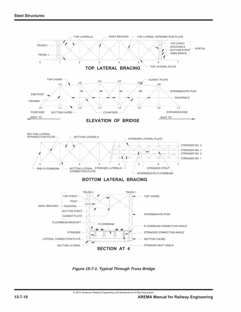
Steel Structures
© 2015, American Railway Engineering and Maintenance-of-Way Association
15-7-10 AREMA Manual for Railway Engineering
Figure 15-7-1. Typical Through Truss Bridge
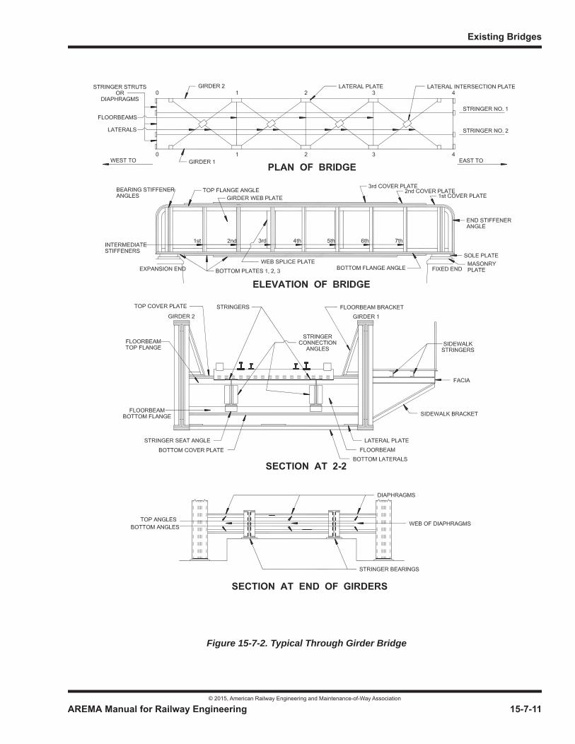
Existing Bridges
© 2015, American Railway Engineering and Maintenance-of-Way Association
AREMA Manual for Railway Engineering 15-7-11
1
3
4
Figure 15-7-2. Typical Through Girder Bridge
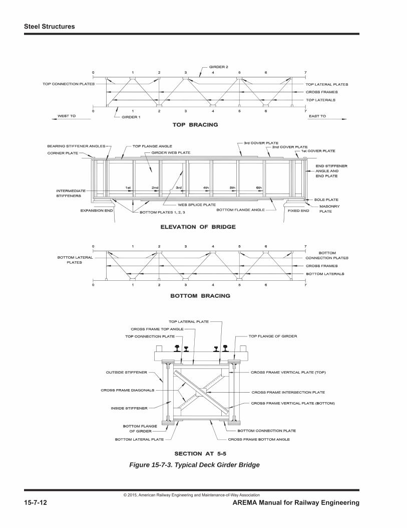
Steel Structures
© 2015, American Railway Engineering and Maintenance-of-Way Association
15-7-12 AREMA Manual for Railway Engineering
Figure 15-7-3. Typical Deck Girder Bridge

Existing Bridges
© 2015, American Railway Engineering and Maintenance-of-Way Association
AREMA Manual for Railway Engineering 15-7-13
1
3
4
SECTION 7.3 RATING1
7.3.1 GENERAL (2015)2
a. Rating of existing bridges in terms of carrying capacity shall be determined by the computation of stresses based on authentic records of the design, details, materials, workmanship and physical condition, including data obtained by inspection (and tests if the records are not complete). If deemed advisable, field determination of stresses shall be made and the results given due consideration in the final assignment of the structure carrying capacity. For a specific service, the location of the bridge and its behavior under load shall be taken into account.
b. Bridges may be assigned two types of ratings; NORMAL and MAXIMUM. The rating or ratings to be assigned, with any corresponding service limitations, shall be as directed by the Engineer.
c. Ratings obtained using the recommendations in this chapter assume that details of design are consistent with those recommended in the Chapter.
Ratings may be done for bridges that have design details which are not recommended in the Chapter. In cases where defects are found in inconsistent details, the Engineer should give priority to the results of inspections and engineering judgment supported by relevant calculations.
7.3.1.1 Normal Rating
a. Normal Rating is the load level which can be carried by the existing structure for its expected service life. The rating is dependent on a specified speed, as impact reductions are allowed for reduced speeds per Article 7.3.2.3. The speed or speeds to be used shall be as directed by the Engineer. Allowable stresses for Normal Rating shall be those specified in Part 1, Design; Section 1.4, Basic Allowable Stresses, supplemented by Part 1, Design, Article 1.3.14.3. The fatigue requirements of Article 7.3.3.2 shall be included, unless a remaining fatigue service life calculation is made.
b. When the allowable stress in Part 1, Design; Section 1.4, Basic Allowable Stresses is expressed in terms of Fy, Fy = yield strength of the material as explained in Article 7.3.3.3a.
c. If the Normal Rating is greater than the Maximum Rating, the lesser rating shall govern.
7.3.1.2 Maximum Rating
a. Maximum Rating is the load level, (see Article 7.3.2) which the structure can support at infrequent intervals, with any applicable speed restrictions. Allowable stresses for Maximum Rating shall be those specified in Article 7.3.3.3. The provisions of Article 7.3.3.2, Fatigue need not be considered when determining Maximum Rating.
b. The Engineer may authorize load levels up to Maximum Rating at more frequent intervals, recognizing that the remaining useful life of the bridge may be significantly shortened. See Part 9, Commentary Article 9.7.3.1.2.
7.3.2 LOADS AND FORCES (2014)3 R(2015)
Bridges shall be analyzed for the following loads and resulting forces:
a. Dead load.
1 References, Vol. 22, 1921, pp. 379, 1006; Vol. 37, 1936, pp. 266, 729, 1024; Vol. 39, 1938, pp. 165, 891; Vol. 41, 1940, pp. 411, 858; Vol. 42, 1941, pp. 358, 874; Vol. 44, 1943, pp. 403, 670, 685; Vol. 50, 1949, pp. 428, 749; Vol. 51, 1950, pp. 444, 904; Vol. 52, 1951, pp. 446, 868; Vol. 59, 1958, pp. 701, 1195; Vol. 60, 1959, pp. 507, 1098; Vol. 63, 1962, pp. 387, 699; Vol. 68, 1967, p. 351; Vol. 73, 1972, p. 176; Vol. 92, 1991, p. 79; Vol. 94, 1994, p. 144; Vol. 97, p. 176.
2 See Part 9 Commentary3 See Part 9 Commentary
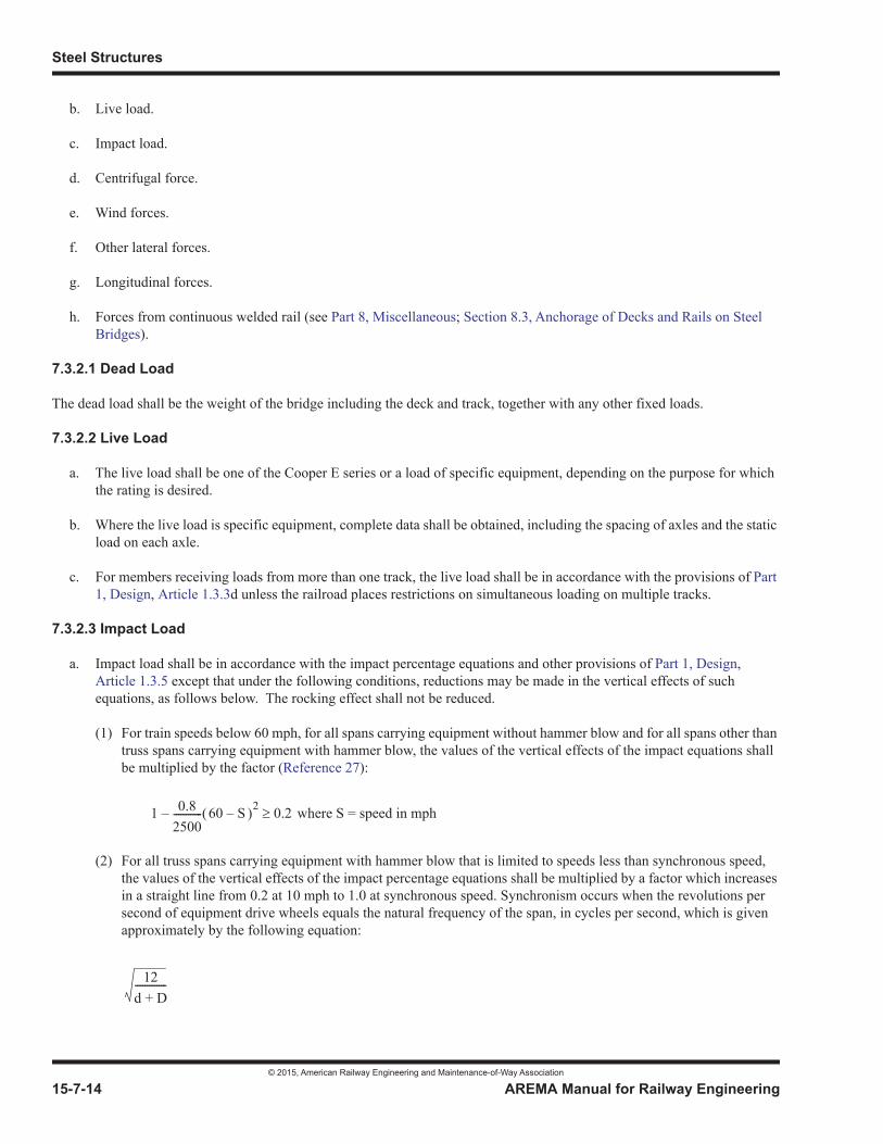
Steel Structures
© 2015, American Railway Engineering and Maintenance-of-Way Association
15-7-14 AREMA Manual for Railway Engineering
b. Live load.
c. Impact load.
d. Centrifugal force.
e. Wind forces.
f. Other lateral forces.
g. Longitudinal forces.
h. Forces from continuous welded rail (see Part 8, Miscellaneous; Section 8.3, Anchorage of Decks and Rails on Steel Bridges).
7.3.2.1 Dead Load
The dead load shall be the weight of the bridge including the deck and track, together with any other fixed loads.
7.3.2.2 Live Load
a. The live load shall be one of the Cooper E series or a load of specific equipment, depending on the purpose for which the rating is desired.
b. Where the live load is specific equipment, complete data shall be obtained, including the spacing of axles and the static load on each axle.
c. For members receiving loads from more than one track, the live load shall be in accordance with the provisions of Part1, Design, Article 1.3.3d unless the railroad places restrictions on simultaneous loading on multiple tracks.
7.3.2.3 Impact Load
a. Impact load shall be in accordance with the impact percentage equations and other provisions of Part 1, Design,Article 1.3.5 except that under the following conditions, reductions may be made in the vertical effects of such equations, as follows below. The rocking effect shall not be reduced.
(1) For train speeds below 60 mph, for all spans carrying equipment without hammer blow and for all spans other than truss spans carrying equipment with hammer blow, the values of the vertical effects of the impact equations shall be multiplied by the factor (Reference 27):
(2) For all truss spans carrying equipment with hammer blow that is limited to speeds less than synchronous speed, the values of the vertical effects of the impact percentage equations shall be multiplied by a factor which increases in a straight line from 0.2 at 10 mph to 1.0 at synchronous speed. Synchronism occurs when the revolutions per second of equipment drive wheels equals the natural frequency of the span, in cycles per second, which is given approximately by the following equation:
1 0.82500------------ 60 S 2 0.2 where S = speed in mph––
12d D+-------------
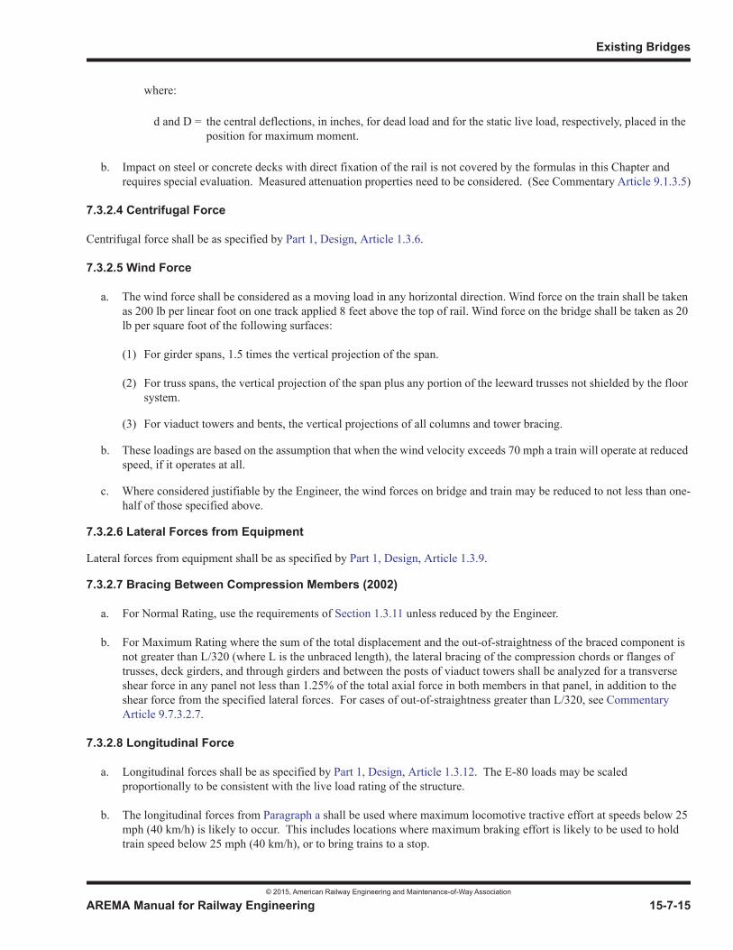
Existing Bridges
© 2015, American Railway Engineering and Maintenance-of-Way Association
AREMA Manual for Railway Engineering 15-7-15
1
3
4
where:
b. Impact on steel or concrete decks with direct fixation of the rail is not covered by the formulas in this Chapter and requires special evaluation. Measured attenuation properties need to be considered. (See Commentary Article 9.1.3.5)
7.3.2.4 Centrifugal Force
Centrifugal force shall be as specified by Part 1, Design, Article 1.3.6.
7.3.2.5 Wind Force
a. The wind force shall be considered as a moving load in any horizontal direction. Wind force on the train shall be taken as 200 lb per linear foot on one track applied 8 feet above the top of rail. Wind force on the bridge shall be taken as 20 lb per square foot of the following surfaces:
(1) For girder spans, 1.5 times the vertical projection of the span.
(2) For truss spans, the vertical projection of the span plus any portion of the leeward trusses not shielded by the floor system.
(3) For viaduct towers and bents, the vertical projections of all columns and tower bracing.
b. These loadings are based on the assumption that when the wind velocity exceeds 70 mph a train will operate at reduced speed, if it operates at all.
c. Where considered justifiable by the Engineer, the wind forces on bridge and train may be reduced to not less than one-half of those specified above.
7.3.2.6 Lateral Forces from Equipment
Lateral forces from equipment shall be as specified by Part 1, Design, Article 1.3.9.
7.3.2.7 Bracing Between Compression Members (2002)
a. For Normal Rating, use the requirements of Section 1.3.11 unless reduced by the Engineer.
b. For Maximum Rating where the sum of the total displacement and the out-of-straightness of the braced component is not greater than L/320 (where L is the unbraced length), the lateral bracing of the compression chords or flanges of trusses, deck girders, and through girders and between the posts of viaduct towers shall be analyzed for a transverse shear force in any panel not less than 1.25% of the total axial force in both members in that panel, in addition to the shear force from the specified lateral forces. For cases of out-of-straightness greater than L/320, see CommentaryArticle 9.7.3.2.7.
7.3.2.8 Longitudinal Force
a. Longitudinal forces shall be as specified by Part 1, Design, Article 1.3.12. The E-80 loads may be scaled proportionally to be consistent with the live load rating of the structure.
b. The longitudinal forces from Paragraph a shall be used where maximum locomotive tractive effort at speeds below 25 mph (40 km/h) is likely to occur. This includes locations where maximum braking effort is likely to be used to hold train speed below 25 mph (40 km/h), or to bring trains to a stop.
d and D = the central deflections, in inches, for dead load and for the static live load, respectively, placed in the position for maximum moment.
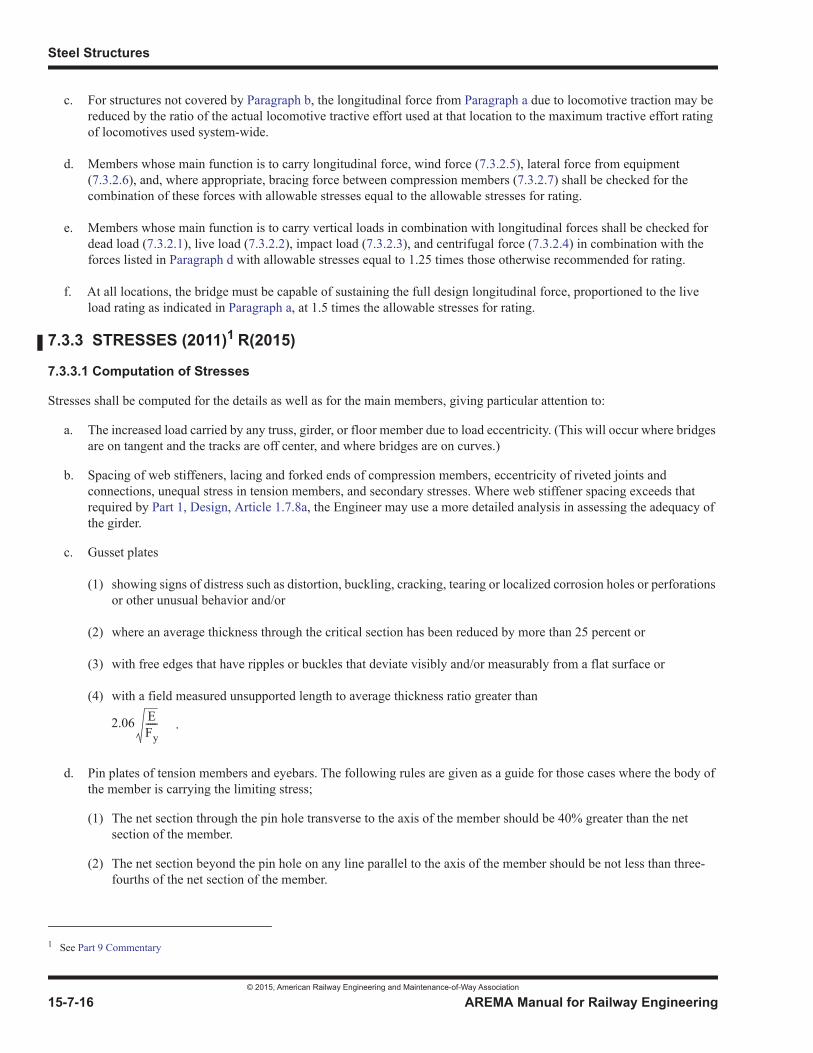
Steel Structures
© 2015, American Railway Engineering and Maintenance-of-Way Association
15-7-16 AREMA Manual for Railway Engineering
c. For structures not covered by Paragraph b, the longitudinal force from Paragraph a due to locomotive traction may be reduced by the ratio of the actual locomotive tractive effort used at that location to the maximum tractive effort rating of locomotives used system-wide.
d. Members whose main function is to carry longitudinal force, wind force (7.3.2.5), lateral force from equipment (7.3.2.6), and, where appropriate, bracing force between compression members (7.3.2.7) shall be checked for the combination of these forces with allowable stresses equal to the allowable stresses for rating.
e. Members whose main function is to carry vertical loads in combination with longitudinal forces shall be checked for dead load (7.3.2.1), live load (7.3.2.2), impact load (7.3.2.3), and centrifugal force (7.3.2.4) in combination with the forces listed in Paragraph d with allowable stresses equal to 1.25 times those otherwise recommended for rating.
f. At all locations, the bridge must be capable of sustaining the full design longitudinal force, proportioned to the live load rating as indicated in Paragraph a, at 1.5 times the allowable stresses for rating.
7.3.3 STRESSES (2011)1 R(2015)
7.3.3.1 Computation of Stresses
Stresses shall be computed for the details as well as for the main members, giving particular attention to:
a. The increased load carried by any truss, girder, or floor member due to load eccentricity. (This will occur where bridges are on tangent and the tracks are off center, and where bridges are on curves.)
b. Spacing of web stiffeners, lacing and forked ends of compression members, eccentricity of riveted joints and connections, unequal stress in tension members, and secondary stresses. Where web stiffener spacing exceeds that required by Part 1, Design, Article 1.7.8a, the Engineer may use a more detailed analysis in assessing the adequacy of the girder.
c. Gusset plates
(1) showing signs of distress such as distortion, buckling, cracking, tearing or localized corrosion holes or perforations or other unusual behavior and/or
(2) where an average thickness through the critical section has been reduced by more than 25 percent or
(3) with free edges that have ripples or buckles that deviate visibly and/or measurably from a flat surface or
(4) with a field measured unsupported length to average thickness ratio greater than
d. Pin plates of tension members and eyebars. The following rules are given as a guide for those cases where the body of the member is carrying the limiting stress;
(1) The net section through the pin hole transverse to the axis of the member should be 40% greater than the net section of the member.
(2) The net section beyond the pin hole on any line parallel to the axis of the member should be not less than three-fourths of the net section of the member.
1 See Part 9 Commentary
2.06 EFy----- .
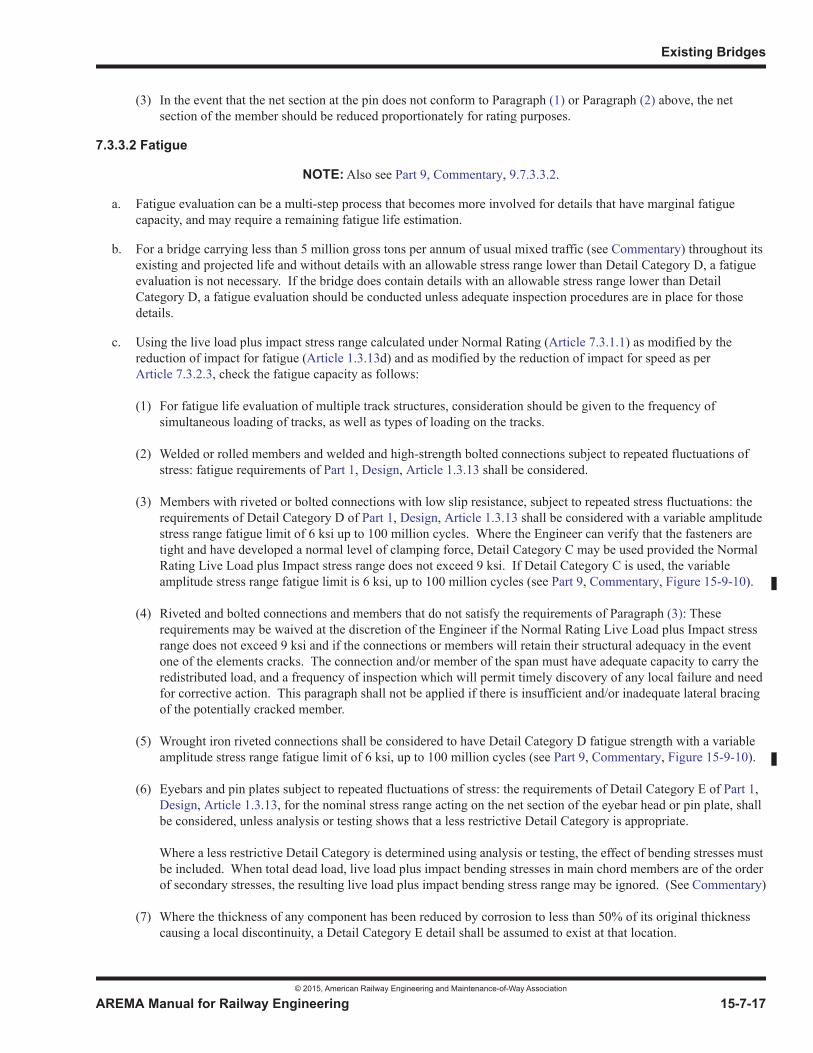
Existing Bridges
© 2015, American Railway Engineering and Maintenance-of-Way Association
AREMA Manual for Railway Engineering 15-7-17
1
3
4
(3) In the event that the net section at the pin does not conform to Paragraph (1) or Paragraph (2) above, the net section of the member should be reduced proportionately for rating purposes.
7.3.3.2 Fatigue
NOTE: Also see Part 9, Commentary, 9.7.3.3.2.
a. Fatigue evaluation can be a multi-step process that becomes more involved for details that have marginal fatigue capacity, and may require a remaining fatigue life estimation.
b. For a bridge carrying less than 5 million gross tons per annum of usual mixed traffic (see Commentary) throughout its existing and projected life and without details with an allowable stress range lower than Detail Category D, a fatigue evaluation is not necessary. If the bridge does contain details with an allowable stress range lower than Detail Category D, a fatigue evaluation should be conducted unless adequate inspection procedures are in place for those details.
c. Using the live load plus impact stress range calculated under Normal Rating (Article 7.3.1.1) as modified by the reduction of impact for fatigue (Article 1.3.13d) and as modified by the reduction of impact for speed as per Article 7.3.2.3, check the fatigue capacity as follows:
(1) For fatigue life evaluation of multiple track structures, consideration should be given to the frequency of simultaneous loading of tracks, as well as types of loading on the tracks.
(2) Welded or rolled members and welded and high-strength bolted connections subject to repeated fluctuations of stress: fatigue requirements of Part 1, Design, Article 1.3.13 shall be considered.
(3) Members with riveted or bolted connections with low slip resistance, subject to repeated stress fluctuations: the requirements of Detail Category D of Part 1, Design, Article 1.3.13 shall be considered with a variable amplitude stress range fatigue limit of 6 ksi up to 100 million cycles. Where the Engineer can verify that the fasteners are tight and have developed a normal level of clamping force, Detail Category C may be used provided the Normal Rating Live Load plus Impact stress range does not exceed 9 ksi. If Detail Category C is used, the variable amplitude stress range fatigue limit is 6 ksi, up to 100 million cycles (see Part 9, Commentary, Figure 15-9-10).
(4) Riveted and bolted connections and members that do not satisfy the requirements of Paragraph (3): These requirements may be waived at the discretion of the Engineer if the Normal Rating Live Load plus Impact stress range does not exceed 9 ksi and if the connections or members will retain their structural adequacy in the event one of the elements cracks. The connection and/or member of the span must have adequate capacity to carry the redistributed load, and a frequency of inspection which will permit timely discovery of any local failure and need for corrective action. This paragraph shall not be applied if there is insufficient and/or inadequate lateral bracing of the potentially cracked member.
(5) Wrought iron riveted connections shall be considered to have Detail Category D fatigue strength with a variable amplitude stress range fatigue limit of 6 ksi, up to 100 million cycles (see Part 9, Commentary, Figure 15-9-10).
(6) Eyebars and pin plates subject to repeated fluctuations of stress: the requirements of Detail Category E of Part 1,Design, Article 1.3.13, for the nominal stress range acting on the net section of the eyebar head or pin plate, shall be considered, unless analysis or testing shows that a less restrictive Detail Category is appropriate.
Where a less restrictive Detail Category is determined using analysis or testing, the effect of bending stresses must be included. When total dead load, live load plus impact bending stresses in main chord members are of the order of secondary stresses, the resulting live load plus impact bending stress range may be ignored. (See Commentary)
(7) Where the thickness of any component has been reduced by corrosion to less than 50% of its original thickness causing a local discontinuity, a Detail Category E detail shall be assumed to exist at that location.
Steel Structures
© 2015, American Railway Engineering and Maintenance-of-Way Association
15-7-18 AREMA Manual for Railway Engineering
d. If the detail being examined does not meet the requirements above, the remaining safe fatigue life needs to be estimated based on past and future traffic. Use Paragraphs (1), (2) and (3) below in place of Article 7.3.3.2c(3) and (4). (See Commentary for further suggestions.)
(1) Members with riveted or bolted connections with low slip resistance, subject to repeated stress fluctuations: the requirements of Detail Category D of Part 1, Design, Article 1.3.13 shall be considered with a variable amplitude stress range fatigue limit of 6 ksi up to 100 million cycles. Where the Engineer can verify that the fasteners are tight and have developed a normal level of clamping force, Detail Category C may be used provided the Root-Mean-Cube (RMC) stress range (SRe) does not and will not exceed 9 ksi. If Detail Category C is used, the variable amplitude stress range fatigue limit is 6 ksi, up to 100 million cycles (See Part 9, Commentary, Figure 15-9-10).
(2) Riveted and bolted connections and members that do not satisfy the requirements of Paragraph (1): These requirements may be waived at the discretion of the Engineer if the Root-Mean-Cube (RMC) stress range (SRe)does not and will not exceed 9 ksi and if the connections or members will retain their structural adequacy in the event one of the elements cracks. The connection and/or member of the span must have adequate capacity to carry the redistributed load, and a frequency of inspection which will permit timely discovery of any local failure and need for corrective action. This paragraph shall not be applied if there is insufficient and/or inadequate lateral bracing of the potentially cracked member.
(3) Riveted connections where the holes for these connections were drilled or reamed may be evaluated using the criteria given in Part 9, Commentary, Figure 15-9-10.
e. Where the actual stress cycles can be estimated from traffic records and future estimated traffic, an effective stress range can be determined for the total number of variable stress cycles, Nv, as
The combination of SRe and Nv for the applicable fatigue detail must be less than the fatigue strength curves shown in Part 9, Commentary, Figure 15-9-3 and/or Figure 15-9-10. The appropriate value of shall be taken from Part 9,Table 15-9-1, unless an appropriate analysis provides a more accurate estimate. The terms i, SRi and are defined in Part 9, Commentary, Article 9.1.3.13l.
f. For Non-Welded Details:
For Detail Category D details and better: If the number of cycles with stress ranges above the Constant Amplitude Fatigue Limit (CAFL) exceeds 0.1% of the spectrum considered, the CAFL is deemed not to exist and the detail line is extended below the CAFL. (See Part 9, Commentary, Figure 15-9-10). Stress ranges that fall below a value of 0.5 of the CAFL should be ignored.
For Detail Category E and E’ details: If the number of cycles with stress ranges above the CAFL exceeds 0.1% of the spectrum considered, the CAFL is deemed not to exist and the detail line is extended below the CAFL. (See Part 9,Commentary, Figure 15-9-10). Stress ranges that fall below a value of 0.25 of the CAFL should be ignored.
For Riveted Details: Stress ranges that cause the RMC stress range to fall below the Variable Amplitude Fatigue Limit (VAFL) of 6 ksi should be ignored provided the total number of relevant cycles does not exceed 100 million.
g. For Welded and Heat Treated Details (Reference 58):
SRe = α (Σ γi SRi3) 1/3
Existing Bridges
© 2015, American Railway Engineering and Maintenance-of-Way Association
AREMA Manual for Railway Engineering 15-7-19
1
3
4
For Detail Category C details and better: If the number of cycles with stress ranges above CAFL exceeds 0.05% of the spectrum considered, the CAFL is deemed not to exist and the detail line is extended below the CAFL. (See Part 9,Commentary, Figure 15-9-10). Stress ranges that fall below a value of 0.5 of the CAFL should be ignored.
For Detail Category D details: If the number of cycles with stress ranges above the CAFL exceeds 0.01% of the spectrum considered, the CAFL is deemed not to exist and the detail line is extended below the CAFL. (See Part 9,Commentary, Figure 15-9-10). Stress ranges that fall below a value of 0.5 of the CAFL should be ignored.
For Detail Category E and E’ details: If the number of cycles with stress ranges above the CAFL exceeds 0.01% of the spectrum considered, the CAFL is deemed not to exist and the detail line is extended below the CAFL. (See Part 9,Commentary, Figure 15-9-10). Stress ranges that fall below a value of 0.25 of the CAFL should be ignored.
h. Fracture Critical Members with Detail Category D, E and E’ details shall be given special attention. Inspection procedures shall be adequate to identify Fracture Critical Members and to detect flaws or cracks before serious damage occurs from uncontrolled propagation. The actual loads and load history shall be considered for computing stress ranges and corresponding stress cycles as opposed to theoretical loads.
7.3.3.3 Allowable Stresses for Maximum Rating
a. Allowable Maximum Rating stress shall be based on either the minimum yield strength or the minimum ultimate tensile strength of the material as determined from tests or records. In the absence thereof,
The yield strength shall be taken as 30,000 psi for open-hearth or Bessemer steel, 25,000 psi for wrought iron, 45,000 psi for silicon steel and 50,000 psi for nickel steel.
The ultimate tensile strength shall be taken as 60,000 psi for open-hearth, 50,000 psi for Bessemer steel, 45,000 psi for wrought iron, 62,000 psi for silicon steel and 90,000 psi for nickel steel.
b. Allowable unit stresses resulting from the loads and forces described in the preceding articles are shown in Table 15-7-1.
Where:
For open-hearth steels (including A7, A36 and similar subsequent steels), High Performance Steels (HPS), and wrought iron:
For Bessemer, silicon and high-strength steels other than High Performance Steels (HPS):
For nickel steel:
E = modulus of elasticity of the material, psiFy = yield strength of the material, psi
Fu = ultimate tensile strength of the material, psi
K = 0.8 Fy
K1 = 0.67 Fu
K = 0.7 Fy
K1 = 0.58 Fu
K = 0.65 Fy
K1 = 0.54 Fu
Steel Structures
© 2015, American Railway Engineering and Maintenance-of-Way Association
15-7-20 AREMA Manual for Railway Engineering
For weld steel:
All other nomenclature is as defined in Part 1 Design, Article 1.4.1 and Article 1.3.14.1.
K = 0.7 Fy
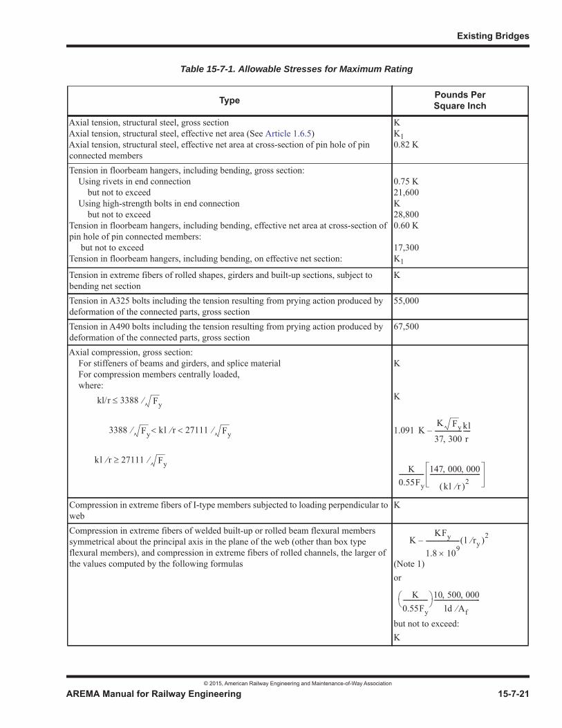
Existing Bridges
© 2015, American Railway Engineering and Maintenance-of-Way Association
AREMA Manual for Railway Engineering 15-7-21
1
3
4
Table 15-7-1. Allowable Stresses for Maximum Rating
Type Pounds PerSquare Inch
Axial tension, structural steel, gross sectionAxial tension, structural steel, effective net area (See Article 1.6.5)Axial tension, structural steel, effective net area at cross-section of pin hole of pin connected members
KK10.82 K
Tension in floorbeam hangers, including bending, gross section: Using rivets in end connection but not to exceed Using high-strength bolts in end connection but not to exceedTension in floorbeam hangers, including bending, effective net area at cross-section of pin hole of pin connected members: but not to exceedTension in floorbeam hangers, including bending, on effective net section:
0.75 K21,600K28,8000.60 K
17,300K1
Tension in extreme fibers of rolled shapes, girders and built-up sections, subject to bending net section
K
Tension in A325 bolts including the tension resulting from prying action produced by deformation of the connected parts, gross section
55,000
Tension in A490 bolts including the tension resulting from prying action produced by deformation of the connected parts, gross section
67,500
Axial compression, gross section: For stiffeners of beams and girders, and splice material For compression members centrally loaded, where:
K
K
1.091
Compression in extreme fibers of I-type members subjected to loading perpendicular to web
K
Compression in extreme fibers of welded built-up or rolled beam flexural members symmetrical about the principal axis in the plane of the web (other than box type flexural members), and compression in extreme fibers of rolled channels, the larger of the values computed by the following formulas (Note 1)
or
but not to exceed:K
kl/r 3388 Fy
3388 Fy kl r 27111 Fy
kl r 27111 Fy
KK Fy
37 300------------------kl
r-----–
K0.55Fy---------------- 147 000 000
kl r 2---------------------------------
KKFy
1.8 109---------------------- l ry
2–
K0.55Fy
---------------- 10 500 000ld Af
------------------------------
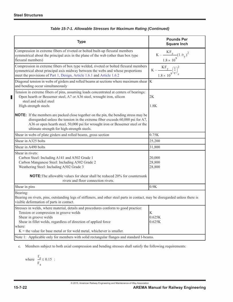
Steel Structures
© 2015, American Railway Engineering and Maintenance-of-Way Association
15-7-22 AREMA Manual for Railway Engineering
c. Members subject to both axial compression and bending stresses shall satisfy the following requirements:
where :
Compression in extreme fibers of riveted or bolted built-up flexural members symmetrical about the principal axis in the plane of the web (other than box type flexural members)Compression in extreme fibers of box type welded, riveted or bolted flexural members symmetrical about principal axis midway between the webs and whose proportions meet the provisions of Part 1, Design, Article 1.6.1 and Article 1.6.2Diagonal tension in webs of girders and rolled beams at sections where maximum shear and bending occur simultaneously
K
Tension in extreme fibers of pins, assuming loads concentrated at centers of bearings: Open hearth or Bessemer steel, A7 or A36 steel, wrought iron, silicon steel and nickel steel High-strength steels
NOTE: If the members are packed close together on the pin, the bending stress may be disregarded unless the tension in the extreme fiber exceeds 60,000 psi for A7, A36 or open hearth steel, 50,000 psi for wrought iron or Bessemer steel or the ultimate strength for high-strength steels.
2K
1.8K
Shear in webs of plate girders and rolled beams, gross section 0.75KShear in A325 bolts 25,200Shear in A490 bolts 31,800Shear in rivets: Carbon Steel: Including A141 and A502 Grade 1 Carbon Manganese Steel: Including A502 Grade 2 Weathering Steel: Including A502 Grade 3
NOTE:The allowable values for shear shall be reduced 20% for countersunk rivets and floor connection rivets.
20,00028,80028,800
Shear in pins 0.9KBearing:Bearing on rivets, pins, outstanding legs of stiffeners, and other steel parts in contact, may be disregarded unless there is visible deformation of parts in contact.Stresses in welds, where material, details and procedures conform to good practice: Tension or compression in groove welds Shear in groove welds Shear in fillet welds, regardless of direction of applied forcewhere: K = the value for base metal or for weld metal, whichever is smaller.
K0.625K0.625K
Note 1: Applicable only for members with solid rectangular flanges and standard I-beams.
Table 15-7-1. Allowable Stresses for Maximum Rating (Continued)
Type Pounds PerSquare Inch
KKFy
1.8 109---------------------- l ry
2–
KKFy
1.8 109---------------------- l
r--
e
2–
f a
Fa----- 0.15

Existing Bridges
© 2015, American Railway Engineering and Maintenance-of-Way Association
AREMA Manual for Railway Engineering 15-7-23
1
3
4
where :
and, in addition, at points braced in the planes of bending,
For nomenclature, see Paragraph (b) above.
d. For members subject to both axial tension and bending, the total of the axial tensile stress and the combined bending tensile stresses about both axes shall not exceed K. However, the compression stresses, if any, in the extreme fibers of flexural members resulting from the combined bending compressive stresses about both axes and the minimum simultaneous axial tension stress shall not exceed the values allowed by the formulas of paragraph b above.
e. Secondary stresses due to truss distortion usually need not be considered in any member the width of which, measured parallel to the plane of distortion, is less than 1/10 of its length. Where the secondary stress exceeds 4,000 psi for tension members and 3,000 psi for compression members, the excess shall be treated as primary stress.
7.3.4 ACTION TO BE TAKEN (2002) R(2008)
a. When the stresses under load are found to exceed allowable values for the selected type of rating (see Article 7.3.1),one or both of the following actions shall be taken:
(1) The train speed, load intensity, or load configuration, or a combination of these, shall be restricted to that which does not develop stresses in excess of allowable.
(2) The bridge shall be strengthened or replaced.
b. When the stresses under load are found to closely approach allowable values for the selected type of rating (see Article 7.3.1), or when the physical condition of main members or details is not satisfactory, the bridge shall be inspected at an increased frequency prescribed by the Engineer, with particular attention given to the critical members or details.
f a
Fa-----
f b1
Fb1--------
f b2
Fb2-------- 1.0+ +
f a
Fa----- 0.15
f a
Fa-----
f b1
Fb1 1f a
0.741 2E-----------------------
k1l1r1
----------2
–
-------------------------------------------------------------------f b2
Fb2 1f a
0.741 2E-----------------------
k2l2r2
----------2
–
------------------------------------------------------------------- 1.0+ +
f a
K----
f b1
Fb1--------
f b2
Fb2-------- 1.0+ +
Steel Structures
© 2015, American Railway Engineering and Maintenance-of-Way Association
15-7-24 AREMA Manual for Railway Engineering
SECTION 7.4 REPAIR, STRENGTHENING AND RETROFITTING1
7.4.1 GENERAL (2009)
a. The repair, strengthening, or retrofitting of existing bridges is usually brought about by one or more of the following conditions:
• Category 1 – Accidental Damage. Sudden unexpected damage resulting from vehicular collision, marine collision, derailment, wide loads, fire, vandalism, seismic activity, or other emergency event.
• Category 2 – Deterioration Damage. Damage resulting from corrosion, fatigue, settlement, past improper repair of the structure, etc.
• Category 3 – Capacity or Geometric Deficiency. Insufficient capacity to carry current loads, vertical or horizontal clearance deficiency, non-compliance with current standards and practices, and/or poor structural details.
• Category 4 – Natural Hazard Deficiency. Potential damage resulting from future seismic events, increased flood levels, or increased wind loads.
The methods used to accomplish the repair, strengthening, or retrofitting of steel structures for the four categories of damage or deficiency may be different in terms of acceptable details, allowable stresses, and acceptable results. What may be acceptable for the emergency repair of accidental damage to a structure to restore traffic may not be acceptable for permanent repairs.
b. The decision to repair, strengthen, retrofit, or to replace a structure should take into account the condition of the structure, the age of the structure, the material of which the various members are made, the fatigue effect of the live loads that have been operated over the structure, the comparative estimated costs, the added length of life to be obtained from the modified bridge, and the possible future increase in the live loading.
7.4.1.1 Physical Condition
a. The physical condition of the structure shall be determined by inspection.
b. The materials of which the members are made shall be determined together with their relevant properties. While this information may be determined by examining the drawings, specifications, or test records, in some situations it may be necessary to obtain test coupons from the structure or to employ appropriate field testing methods such as the emery wheel/spark test and portable Brinell testing.
7.4.1.2 Stresses
a. The permissible stresses in repaired, strengthened, or retrofitted members shall be in compliance with the design stresses specified in Part 1, Design, except that in certain circumstances, rating stresses as specified in Section 7.3, Rating, or other stress levels, may be used as determined by the Engineer.
b. In adding metal to stringers, floorbeams or girders, or to members of trusses and viaducts, the new material shall be considered effective in carrying its proportion of live loads only, unless the dead load stress can be removed temporarily, or some other means is provided to introduce the proper dead load stress in the new metal when it is applied. Connections of adequate strength shall be provided for the added metal.
1 References, Vol. 36, 1935, pp. 685, 1008; Vol. 39, 1938, pp. 165, 891; Vol. 53, 1952, pp. 511, 1063; Vol. 63, 1962, pp. 387, 699; Vol. 64, 1963, pp. 367, 633; Vol. 70, 1969, p. 241; Vol. 96, p. 73; Vol 97, p 175.
Existing Bridges
© 2015, American Railway Engineering and Maintenance-of-Way Association
AREMA Manual for Railway Engineering 15-7-25
1
3
4
c. Where the added material carries its proportion of the live load only, the stresses in the remaining portion of the original members, which is carrying the total dead load as well as its portion of live load, shall be investigated for the live load for which the bridge is being repaired or strengthened. The added material may be considered fully effective in computing the radius of gyration for determination of allowable stress in axially loaded compression members.
d. Members to be repaired or strengthened shall be investigated for any decrease in strength or stability resulting from the temporary removal of rivets, bolts, lacing, batten plates, cover plates or other parts. Bolts required for sealing only may be omitted temporarily during the repair process. In some cases, falsework or temporary members may be required. Where compression members are being reinforced, lacing bars, batten plates or tie plates, if removed, shall be restored to an acceptable level before allowing traffic over the bridge.
7.4.1.3 Eccentricity
The added material shall be applied so as to produce a balanced section, eliminating or minimizing the effect of eccentricity onthe strengthened member. Where balanced section cannot be obtained economically the eccentricity of the member shall be taken into account in determining the stresses.
7.4.1.4 Fasteners
a. Existing rivets that are removed to effect a repair or strengthening shall be replaced on a one for one basis with high-strength bolts of equal or greater diameter.
b. Where remaining safe fatigue life is a controlling limit state, existing rivet holes shall be reamed after removal of the rivets, and the replacement high-strength bolt shall be one size larger in nominal diameter than the replaced rivet or if of the same diameter shall satisfy the requirements for an oversize hole unless the hole is examined and found to contain no significant flaws or stress raisers.
c. Rivet heads may be removed by either mechanical means or careful use of oxygen-fuel gas cutting methods. If the oxygen-fuel gas method is used, use of a rivet cutting tip is recommended. Where existing material is to be preserved for reuse, rivet shanks shall be removed by mechanical means only, with coring permitted to assist the mechanical removal; the coring process shall not penetrate the surface of the rivet shank. Where existing material is to be discarded, rivets may be removed by any appropriate means acceptable to the Engineer.
d. If a rivet hole has been scored or otherwise damaged, the hole shall be reamed and the replacement high-strength bolt shall be one size larger in nominal diameter than the replaced rivet, or if of the same diameter shall satisfy the requirements for an oversize hole.
e. Existing high-strength bolts removed to effect a repair or strengthening may be reused only under conditions approved by the Engineer. If unacceptable to the Engineer, they shall be replaced with new high-strength bolts of equivalent diameter.
f. The extent of contamination of the faying surfaces by damage, mill scale, paint, grease, etc. shall be considered by the Engineer in assigning the allowable shear values for high-strength bolts used in repair, strengthening or retrofitting applications.
g. Type 3 high-strength bolts shall be used with weathering steel. Galvanized bolts shall not be used with uncoated steel.
7.4.1.5 Welding
a. Electric arc welding may be employed subject to the approval of the Engineer.
b. In general, welds shall not be assumed to act together with rivets or bolts.
Steel Structures
© 2015, American Railway Engineering and Maintenance-of-Way Association
15-7-26 AREMA Manual for Railway Engineering
c. Where welds are added to existing riveted or bolted connections, the welds shall be designed to transmit the entire force, except that in such members where the existing material carries the entire dead load force, the welds shall be designed to carry the entire live load force in the member. Where some of the existing rivets in a member are loose or defective, they shall be replaced with high-strength bolts properly installed, unless otherwise directed by the Engineer, and such bolts may be considered to carry the dead load stress of the replaced rivets provided they are installed prior to the welding. Loose rivet heads shall not be welded.
d. Welding shall be in accordance with the applicable sections of Part 1, Design, and may be used only where specifically permitted by the Engineer.
e. When welding existing material where mill scale, rust, and dirt are present, and standard surface preparation cannot be accomplished, low hydrogen electrodes shall be used.
f. When difficult-to-weld material must be welded to effect a repair, use of global pre-heats and post-heats shall be considered. Refer to Alternative Pre-Heat Requirements of AWS.
7.4.1.6 Jacking and Temporary Support
a. Jacks shall be placed so that the line of action is as nearly as possible, concentric with the gravity axis of the existing member(s). If jacks must be placed on an eccentric axis, an analysis of the effects of such eccentricity shall be made.
b. The rated capacity of a jack shall be a minimum of 50% greater than the computed required jacking force.
c. When choosing member sizes for jacking, strongbacks, or other temporary support, the allowable stress may be increased by 50%. Attention shall be paid to slenderness ratios and buckling allowables.
d. Live loads of locomotives, cars or similar equipment shall not be supported hydraulically. Other live loads may not be supported hydraulically without prior approval of the engineer.
7.4.1.7 Repair of Cracks and Defects
a. An actively propagating fatigue crack, either load-induced or distortion-induced, may be temporarily repaired by drilling a hole in the member to encompass the crack tip, provided the remaining net section of the member has sufficient stress-carrying capacity. The hole size shall be at least equal to the thickness of the material, but not less than 3/4 inch (19 mm) diameter. Permanent repairs shall consist of measures to reduce the stress range in the case of load-induced fatigue cracking, and to eliminate the causes of the distortion in the case of distortion-induced fatigue cracking.
b. Defects from Category 1 Damage, such as gouges, nicks, burrs, etc., on the surface of fracture critical members shall be repaired by grinding smooth or peening. No weld repair of such surface defects shall be permitted.
7.4.1.8 Heat Straightening
a. Heat straightening may consist of either flame straightening used alone, flame straightening with an auxiliary force, or hot mechanical straightening.
b. Heat straightening of damaged steel members shall not be undertaken by unskilled or inexperienced persons.
c. Heat straightening of damaged steel members shall be undertaken only after due consideration of the stability of the individual member, the stability of the overall structure, and possible redistribution of stresses as a consequence of the heat straightening process.
Existing Bridges
© 2015, American Railway Engineering and Maintenance-of-Way Association
AREMA Manual for Railway Engineering 15-7-27
1
3
4
d. The temperature of the heated steel shall not exceed 1200 degrees F for carbon and low alloy steels, nor 1050 degrees F for quenched and tempered steels. No artificial means of cooling shall be applied until the steel has cooled to below 600 degrees F.
e. Mechanisms to apply auxiliary forces during heat straightening shall be of the type that reduce the magnitude of these auxiliary forces as the member displaces.
7.4.1.9 Bearings
a. Where expansion bearings are frozen in position by accumulated corrosion, they shall not be freed without prior investigation of the stability of the superstructure and substructure elements.
b. Where a bearing has been pounded into the bearing seat, the bearing may be restored to correct elevation by filling the void under the bearing with a suitable grout. If the restoration of the bearing shoe to correct elevation requires an extension above the seat, steel shim plates may be used.
7.4.2 PLATE GIRDERS OR ROLLED BEAMS (2012)1
7.4.2.1 Reinforcing
Reinforcing may be required in practically any part of plate girders or rolled beams. The purpose of such reinforcing is to re-establish or to increase the load carrying capacity of the plate girder or rolled beam. Before implementing any reinforcement,careful consideration should be given to the effects of fatigue on the member that may result from the implementation of such reinforcement.
7.4.2.2 Stiffeners
a. The bearing stiffeners may be reinforced by adding angles or plates, grinding the bearing ends of the new parts to make them fit closely, or welding them to the flanges.
b. Intermediate stiffeners may be added by high-strength bolting, or welding, but they shall not be welded to the tension flange.
7.4.2.3 Flanges and Webs
a. The flange section may be increased by adding cover plates or by replacing an existing cover plate with a new cover plate providing adequate section. Where the exposed surfaces of old cover plates are rough or uneven from the effects of corrosion or tie wear, they shall be discarded and new plates provided. When more than one cover plate must be renewed due to wear, etc., consideration should be given to replacing the defective plates with one plate providing adequate section. Cover plates added to plate girders or rolled beams without existing cover plates shall be full length. All cover plates shall be connected to the flanges with continuous fillet welds or high-strength bolts. Intermittent welds shall not be used. Welded cover plates shall be of sufficient thickness to prevent buckling without intermediate fasteners.
b. In open deck bridges where ties rest directly on the flange angles, worn or inadequate size flange angles may be renewed by bolting in place, new flange angles of sufficient size. Cover plates may be added, where required because of inadequate size flange angles, only when the surface to which they are to be attached has not been severely reduced by corrosion.
1 See Part 9 Commentary
Steel Structures
© 2015, American Railway Engineering and Maintenance-of-Way Association
15-7-28 AREMA Manual for Railway Engineering
c. Where the cost of removal and replacement of the deck would be excessive, as in ballasted-deck bridges, flange sections may be increased by adding full-length longitudinal angles, plates, or channels just below the flange angles, first removing the stiffener angles and then finally replacing them with new stiffeners.
d. Where flange material is added, the existing flange fasteners may be insufficient. This may be corrected by replacing the existing fasteners with high-strength bolts of equal or larger diameter.
e. Holes in flange material may be drilled full size in the shop or in the field or subpunched in the shop and reamed in the shop or in the field. See Articles 3.2.6, 3.2.7 and associated commentary.
f. Where fasteners are removed from two or more plies of material which are to remain in contact, holes shall be filled with a bolt snug tightened before any adjacent fastener is removed, unless otherwise authorized by the Engineer.
g. Where the web was not originally spliced to resist moment, it may be so spliced by adding cover plates or side plates.
7.4.2.4 Initial Tension
Initial tension may be placed in a new bottom cover plate by welding one end of the plate to the flange angles and then heatingthe plate until it has expanded to some predetermined length, welding the other end of the plate, and then allowing it to cool,after which the welding can be completed.
7.4.2.5 Effective Span
Where the bridge seat is wide and in acceptable condition, the effective span may be shortened somewhat by moving the bearings nearer to the edge of the seat and providing new end bearing stiffeners at the new bearing location. Shortening of theeffective span is allowed provided that a thorough analysis of the abutments is performed. Requirements of Chapter 9, Seismic Design for Railway Structures, must be considered.
7.4.2.6 Laterals, Cross Frames and Connections
Inadequate lateral systems, especially those composed of rods or bars, should be replaced with lateral members of the required strength and stiffness connected with high-strength bolts.
Cross frame members, diaphragms and their connections shall be checked for adequacy to carry shear due to unequal distribution of wheel loads and strengthened, if necessary.
7.4.2.7 Doubling Up Girders
In strengthening deck plate girder bridges where there are several identical spans, one method is to double up the spans, and then provide additional spans to complete the bridge. Where girders are so arranged, the spacing should be such as to equalize the load on the girders and to allow inspection, cleaning and painting of the interior surfaces. An adequate system of lateralsand cross frames shall be provided.
7.4.2.8 Substitution
Where extensive strengthening is to be done on a number of identical girder spans, one new span may be provided and substituted for one of the spans which will then be removed and strengthened. Each span in turn can be replaced by a span that has been removed and strengthened, until the entire bridge has been strengthened.

Existing Bridges
© 2015, American Railway Engineering and Maintenance-of-Way Association
AREMA Manual for Railway Engineering 15-7-29
1
3
4
7.4.3 FLOOR SYSTEMS (1993) R(2015)
7.4.3.1 Stringers and Floorbeams
a. Strengthening of riveted or high-strength-bolted plate girder sections shall be done in accordance with applicable requirements of Part 1, Design.
b. Stringer systems may be strengthened by adding cover plates to existing stringers, by adding additional stringers, or by stringer replacement with new sections of adequate strength. Where possible, additional or new stringers shall be standard rolled sections without cover plates rather than built-up sections. Where additional stringers are used they shall be connected to the existing stringers so that they will deflect together. Stringer spacing shall be such as to allow inspection, cleaning and painting of interior surfaces.
c. The webs of floorbeams are likely to be overstressed at the ends, especially in pin-connected truss spans where the ends have been recessed to clear the pin-nuts and eyebars. Floorbeam details shall be analyzed for both flange and web stresses and adequate reinforcement provided.
7.4.3.2 End Connections
The end connection of a stringer may sometimes be strengthened by using longer connecting angles and adding high-strength bolts, by reaming the holes and using larger high-strength bolts, or by welding. Brackets may be placed under the ends of the stringers to give additional support.
7.4.3.3 Lateral Connections
Lateral plates attached to the tension flange of short-span stringers and floorbeams decrease their fatigue strength, and the addition of such plates should be avoided, particularly near points of maximum bending.
7.4.3.4 Substitution
The procedure of Article 7.4.2.8 may be followed where applicable.
7.4.4 TRUSSES (2009)
The strengthening of trusses is more difficult and requires considerably more analysis of the connections and their details thanis required for the strengthening of girders or floor systems. The connections often determine the strength of the truss span.
7.4.4.1 Tension Members
a. Tension members of pin-connected trusses may often be reinforced by the addition of adjustable bars. These may be of several types, such as loop bars, or single bars attached to a loop or forging that fits over and bears on the pin. Care must be taken to form the position of the bar or forging in contact with the pin so that full bearing will be secured. This may be accomplished by providing sufficient metal in this portion for boring the pin holes. Where a bar of uniform section is bent around a pin, the cross section is likely to be reduced by the stretching and narrowing of the outer edge of the bar, for which allowance shall be made. Where space is limited, bars sometimes are placed over the heads of existing eyebars, but this method gives doubtful results, because the edges of the eyebar heads are not finished to a true surface.
b. Except where a single bar can be placed in the exact center of the pin, two additional bars or members equally spaced from the center of the pin, shall be used to strengthen each panel. The resultant stresses in the pins under the revised loading condition must be investigated.
Steel Structures
© 2015, American Railway Engineering and Maintenance-of-Way Association
15-7-30 AREMA Manual for Railway Engineering
c. After the new members have been installed, the entire panel shall be adjusted to properly distribute the dead load tension to all members. Eyebars or rods that do not have adjustable provisions shall be adjusted in accordance with Part8, Miscellaneous; Section 8.2, Method of Shortening Eyebars to Equalize the Stress.
d. Elongated eyebars may be adjusted in accordance with Part 8, Miscellaneous; Section 8.2, Method of Shortening Eyebars to Equalize the Stress.
e. Rolled or built-up sections may be effectively reinforced by the addition of cover plates in the planes of the gusset plates. These plates may be high-strength bolted or welded to the flange of the member and butt welded to the gusset plates, provided that the strength of the gusset plate and its connections is adequate. Care shall be taken to protect against notches or other severe stress concentrations at the connections of the cover plates to the gussets. Unless the dead load force in the original member is relieved, new metal so added shall be considered effective in carrying its portion of the live load stress only.
f. Floorbeam hangers are frequently highly stressed from a combination of bending and direct axial tension. To reduce the probability of fatigue cracking in these highly stressed hangers, sharp copes or re-entrant cuts should be eliminated or modified. The replacement of all rivets with high-strength bolts at the top connection of the floorbeam hangers to improve the transfer of force to the gusset plates should also be considered.
7.4.4.2 Compression Members
a. The reinforcement of compression members requires careful investigation. The chord members of many old bridges are unsymmetrical in section and are eccentrically loaded. This condition may be corrected by adding metal in the proper location. A small amount of metal placed in this way will often increase the rating of the member considerably.
b. Where a substantial increase in the strength of a compression member is required, special analysis is needed. The solution will depend on the type of section, the details at or near the pins, and other conditions. Metal sometimes may be added to the cover plate, usually between the existing lines of rivets. This should be balanced by placing additional metal on the lower flanges in the manner described in the preceding paragraph. Full length side plates may be added to the web plates of the section, between the vertical legs of the upper and lower angles, provided that adequate means of transferring this stress into the connection or adjacent member can be obtained. Where the cover plate in the original design is so wide in proportion to its thickness that it has little resistance to buckling, this may be achieved by adding a cover plate connected by fasteners along the center line in addition to the fasteners through the angles.
c. One of the problems encountered in reinforcing compression members is the introduction of the dead load stress into the additional material. Where this is not done, full value cannot be obtained from the new material. For instance, assuming that the new material gets no dead load stress, that the dead load stress in the old material is 10,000 psi, and that the total allowable stress is 26,000 psi, then the new material will be carrying only 16,000 psi stress from live load only. This is the maximum stress to which the new metal can be worked, since any higher stress would cause overstress in the old metal. Several methods may be used to induce dead load stress in the new material. The new material may be temporarily shortened by cooling or compressing before connecting to the old material or the old material may be temporarily relieved of dead load while adding the new material.
d. The cover plates of large upper chords and end posts may be thin compared with their unsupported width and it may be desired to bring all of the old metal into full use. The reinforcement, in this case, may be provided in the form of a new central web with top and bottom flange angles; and is divided into two segments, each occupying one-half of the panel length. The segments are designed to receive a wedge between their adjacent ends. The segments are placed inside the member with ends bearing against the pins and the center wedge. To introduce compression into the segments, the new material is first seated for proper bearing against the pins or connections; by pulling the wedge up tight by means of a large bolt. The wedges are drawn up a predetermined amount to develop the desired dead load stress in the new metal. The bolts holding the wedges are left in place permanently. The flanges of the new segments are then bolted to the top cover plate and to the lower lacing bars, thus making the new center segment an integral part of the chord, carrying the same stress per square inch as the old metal.
Existing Bridges
© 2015, American Railway Engineering and Maintenance-of-Way Association
AREMA Manual for Railway Engineering 15-7-31
1
3
4
7.4.4.3 Adding a Center Truss
a. The reinforcement of deck truss spans frequently is accomplished by the addition of a center truss. In a single track bridge, this is comparatively simple, as ample bracing may be applied to make the three trusses deflect alike. The center truss should not be too stiff but should have the same deflection under load as the old trusses. Otherwise excessively heavy cross bracing will be required or else excessive stresses will be induced in the center truss before the outer trusses have deflected enough to stress the members up to their safe carrying capacity.
b. In a double-track deck truss span that has only two trusses, the addition of a center truss creates difficult problems. The tracks may be loaded either separately or simultaneously, and it may not be economical to introduce enough bracing between the trusses to make them act together. The floorbeams will be continuous over the new truss. Where the center truss is too stiff, the outer truss will have the greater deflection under a single-track load, and the outer rail will be low under load. When both tracks are loaded, however, the center truss must be strong enough to carry its share of the load from both tracks. Thus the truss deflections and the distribution of stresses through the floorbeams for various conditions of loading must be determined and a design chosen in which the various members will be as stressed as nearly equally as possible under equal stress without introducing objectionable deflections and poor-riding-track. The reinforcement should be designed and erected in such a way that the new center truss may be swung under its own dead load before making the final connections between the new and the old trusses.
7.4.4.4 Auxiliary Truss Supports
It is sometimes possible to shorten the effective length of a truss span by the installation of auxiliary piers or bents at the first or second interior panel points. However, since this converts a simple span truss to a three-span continuous truss, changing itsstress characteristics, a thorough analysis of the altered span must be made. Members having insufficient capacity must be strengthened to carry the revised loading prior to the installation of the new supports.
7.4.4.5 Auxiliary Truss Members
Girders, lattice trusses, floorbeams and stringers may sometimes be reinforced by adding auxiliary truss members underneath.
7.4.5 OTHER STRUCTURES (1983) R(2014)
Viaduct towers and structures of other types not specifically mentioned herein may be strengthened by methods similar to the foregoing.
SECTION 7.5 MAINTENANCE1
7.5.1 GENERAL (1984) R(2014)
a. All steel structures are subject to gradual deterioration due to corrosion, mechanical wear, and impact and fatigue damage from moving loads, and require periodic maintenance throughout their service life.
b. The class of maintenance to be used for each structure shall be determined by the Engineer, based upon the importance of the structure to the operations of the railroad, the cost and difficulty of repair or replacement, and the probable remaining service life required.
c. The extent of maintenance shall be classified as follows:
1 References: Vol. 75, 1974, p. 338.
Steel Structures
© 2015, American Railway Engineering and Maintenance-of-Way Association
15-7-32 AREMA Manual for Railway Engineering
(1) Class A. The structure is maintained in a condition comparable to new construction, except weathering and any deterioration which affects appearance only.
(2) Class B. Main members are maintained to the extent that the rated capacity of the bridge will not be reduced, but secondary members are maintained only as necessary to preclude extensive structural repairs.
(3) Class C. Main members are maintained to the extent necessary to carry the prevailing traffic, and secondary members are maintained only as immediately necessary.
7.5.2 MAINTENANCE OF STRUCTURAL ELEMENTS (2015)1
a. Where inspection reveals that a structural element has been weakened, the Engineer shall determine whether the element shall be replaced or reinforced, based on the extent of loss of strength and the class of the maintenance as defined in Article 7.5.1c.
b. The procedures to be followed in replacing or reinforcing a structural element shall be the same as specified in Section7.3, Rating.
c. Ultrasonic impact treatment (a high-frequency peening process) can be used to introduce compressive residual stresses into the weld toe area to extend the fatigue life of certain weld details that are prone to cracking. This procedure is intended for application only to uncracked weld details.
7.5.3 MAINTENANCE COATING (2001) R(2014)
a. Except in those cases where appearance is an important consideration, the purpose of maintaining the coating or other corrosion protection system on a structure is to protect the structure from deterioration which may affect its rated capacity.
b. The extent of maintenance coating for each structure shall be determined by the Engineer as part of a system bridge maintenance program and shall be consistent with the general class of maintenance as defined in Article 7.5.1c, with consideration being given to the local environment and factors such as relative humidity and type of atmosphere.
c. Steel surfaces to be coated shall be prepared and coated in accordance with the applicable articles of Section 8.7.
1 See Part 9 Commentary
© 2015, American Railway Engineering and Maintenance-of-Way Association 15-8-1
1
3
15Part 8
Miscellaneous
— 2015 —
FOREWORD
Part 1, Design, Part 3, Fabrication, Part 4, Erection and Part 6, Movable Bridges are applicable to turntables except as modified by Section 8.1, Turntables.
TABLE OF CONTENTS
Section/Article Description Page
8.1 Turntables . . . . . . . . . . . . . . . . . . . . . . . . . . . . . . . . . . . . . . . . . . . . . . . . . . . . . . . . . . . . . . . . . . . . . . . . . . . . . 15-8-38.1.1 General Features of Design (2005) R(2014) . . . . . . . . . . . . . . . . . . . . . . . . . . . . . . . . . . . . . . . . . . . . 15-8-38.1.2 Loads and Stresses (2009) R(2014) . . . . . . . . . . . . . . . . . . . . . . . . . . . . . . . . . . . . . . . . . . . . . . . . . . . 15-8-48.1.3 Basic Allowable Stresses and Deflections (2008) R(2014) . . . . . . . . . . . . . . . . . . . . . . . . . . . . . . . . . 15-8-78.1.4 General Details (2009) R(2014). . . . . . . . . . . . . . . . . . . . . . . . . . . . . . . . . . . . . . . . . . . . . . . . . . . . . . 15-8-7
8.2 Method of Shortening Eyebars to Equalize the Stress . . . . . . . . . . . . . . . . . . . . . . . . . . . . . . . . . . . . . . . . . 15-8-118.2.1 General (2013) . . . . . . . . . . . . . . . . . . . . . . . . . . . . . . . . . . . . . . . . . . . . . . . . . . . . . . . . . . . . . . . . . . . 15-8-118.2.2 Procedure (2013) . . . . . . . . . . . . . . . . . . . . . . . . . . . . . . . . . . . . . . . . . . . . . . . . . . . . . . . . . . . . . . . . . 15-8-12
8.3 Anchorage of Decks and Rails on Steel Bridges . . . . . . . . . . . . . . . . . . . . . . . . . . . . . . . . . . . . . . . . . . . . . . 15-8-158.3.1 Foreword (2010) . . . . . . . . . . . . . . . . . . . . . . . . . . . . . . . . . . . . . . . . . . . . . . . . . . . . . . . . . . . . . . . . . 15-8-158.3.2 Anchorage of Decks to Bridge Spans (2012). . . . . . . . . . . . . . . . . . . . . . . . . . . . . . . . . . . . . . . . . . . . 15-8-158.3.3 Anchorage of Rail (2011). . . . . . . . . . . . . . . . . . . . . . . . . . . . . . . . . . . . . . . . . . . . . . . . . . . . . . . . . . . 15-8-168.3.4 Rail Expansion Joints (2012) . . . . . . . . . . . . . . . . . . . . . . . . . . . . . . . . . . . . . . . . . . . . . . . . . . . . . . . . 15-8-178.3.5 Maintenance of Bridges with Continuous Welded Rail (1983) R(2012) . . . . . . . . . . . . . . . . . . . . . . . 15-8-19
8.4 Unloading Pits. . . . . . . . . . . . . . . . . . . . . . . . . . . . . . . . . . . . . . . . . . . . . . . . . . . . . . . . . . . . . . . . . . . . . . . . . . 15-8-198.4.1 Scope and Purpose (2013) . . . . . . . . . . . . . . . . . . . . . . . . . . . . . . . . . . . . . . . . . . . . . . . . . . . . . . . . . . 15-8-198.4.2 General (2013) . . . . . . . . . . . . . . . . . . . . . . . . . . . . . . . . . . . . . . . . . . . . . . . . . . . . . . . . . . . . . . . . . . . 15-8-198.4.3 Operating Limitations (2013). . . . . . . . . . . . . . . . . . . . . . . . . . . . . . . . . . . . . . . . . . . . . . . . . . . . . . . . 15-8-198.4.4 Loads (1993) R(2012) . . . . . . . . . . . . . . . . . . . . . . . . . . . . . . . . . . . . . . . . . . . . . . . . . . . . . . . . . . . . . 15-8-208.4.5 Unsupported Running Rail (2013) . . . . . . . . . . . . . . . . . . . . . . . . . . . . . . . . . . . . . . . . . . . . . . . . . . . . 15-8-268.4.6 Structural Supporting Beams (1993) R(2012) . . . . . . . . . . . . . . . . . . . . . . . . . . . . . . . . . . . . . . . . . . . 15-8-268.4.7 Concrete Pit (2013) . . . . . . . . . . . . . . . . . . . . . . . . . . . . . . . . . . . . . . . . . . . . . . . . . . . . . . . . . . . . . . . 15-8-26
Steel Structures
© 2015, American Railway Engineering and Maintenance-of-Way Association
15-8-2 AREMA Manual for Railway Engineering
TABLE OF CONTENTS (CONT)
Section/Article Description Page
8.4.8 Construction Drawings (2013) . . . . . . . . . . . . . . . . . . . . . . . . . . . . . . . . . . . . . . . . . . . . . . . . . . . . . . 15-8-268.4.9 Industry Owner’s Responsibilities (1983) R(2012) . . . . . . . . . . . . . . . . . . . . . . . . . . . . . . . . . . . . . . 15-8-27
8.5 Walkways, Handrails, and Fixed Ladders on Bridges . . . . . . . . . . . . . . . . . . . . . . . . . . . . . . . . . . . . . . . . 15-8-278.5.1 Locations (2014). . . . . . . . . . . . . . . . . . . . . . . . . . . . . . . . . . . . . . . . . . . . . . . . . . . . . . . . . . . . . . . . . 15-8-278.5.2 Clearances and Minimum Dimensions (2014) . . . . . . . . . . . . . . . . . . . . . . . . . . . . . . . . . . . . . . . . . . 15-8-278.5.3 Loads (2014). . . . . . . . . . . . . . . . . . . . . . . . . . . . . . . . . . . . . . . . . . . . . . . . . . . . . . . . . . . . . . . . . . . . 15-8-288.5.4 Materials (2014) . . . . . . . . . . . . . . . . . . . . . . . . . . . . . . . . . . . . . . . . . . . . . . . . . . . . . . . . . . . . . . . . . 15-8-29
8.6 Guidelines for Evaluating Fire Damaged Steel Railway Bridges . . . . . . . . . . . . . . . . . . . . . . . . . . . . . . . . 15-8-308.6.1 Introduction (1986) R(2015) . . . . . . . . . . . . . . . . . . . . . . . . . . . . . . . . . . . . . . . . . . . . . . . . . . . . . . . 15-8-308.6.2 Types of Fires (1986) R(2015) . . . . . . . . . . . . . . . . . . . . . . . . . . . . . . . . . . . . . . . . . . . . . . . . . . . . . . 15-8-308.6.3 Temperature Effects (2008) R(2015) . . . . . . . . . . . . . . . . . . . . . . . . . . . . . . . . . . . . . . . . . . . . . . . . . 15-8-308.6.4 High-Strength Steels (1985) R(2015). . . . . . . . . . . . . . . . . . . . . . . . . . . . . . . . . . . . . . . . . . . . . . . . . 15-8-318.6.5 Fasteners (1985) R(2015) . . . . . . . . . . . . . . . . . . . . . . . . . . . . . . . . . . . . . . . . . . . . . . . . . . . . . . . . . . 15-8-318.6.6 Evaluation of Bridge (1986) R(2015). . . . . . . . . . . . . . . . . . . . . . . . . . . . . . . . . . . . . . . . . . . . . . . . . 15-8-318.6.7 Conclusion (1986) R(2015) . . . . . . . . . . . . . . . . . . . . . . . . . . . . . . . . . . . . . . . . . . . . . . . . . . . . . . . . 15-8-328.6.8 References (1986) R(2015) . . . . . . . . . . . . . . . . . . . . . . . . . . . . . . . . . . . . . . . . . . . . . . . . . . . . . . . . 15-8-32
8.7 Guide to the Preparation of a Specification for the Cleaning and Coating of Existing Steel Railway Bridges15-8-328.7.1 General (2009) . . . . . . . . . . . . . . . . . . . . . . . . . . . . . . . . . . . . . . . . . . . . . . . . . . . . . . . . . . . . . . . . . . 15-8-328.7.2 Surface Preparation (2009). . . . . . . . . . . . . . . . . . . . . . . . . . . . . . . . . . . . . . . . . . . . . . . . . . . . . . . . . 15-8-408.7.3 Application (2009) . . . . . . . . . . . . . . . . . . . . . . . . . . . . . . . . . . . . . . . . . . . . . . . . . . . . . . . . . . . . . . . 15-8-438.7.4 Coating Systems (2009) . . . . . . . . . . . . . . . . . . . . . . . . . . . . . . . . . . . . . . . . . . . . . . . . . . . . . . . . . . . 15-8-498.7.5 Safety and Environmental Considerations (2009) . . . . . . . . . . . . . . . . . . . . . . . . . . . . . . . . . . . . . . . 15-8-518.7.6 Quality Control and Quality Assurance (2009) . . . . . . . . . . . . . . . . . . . . . . . . . . . . . . . . . . . . . . . . . 15-8-568.7.7 Final Inspection and Warranty (2009) . . . . . . . . . . . . . . . . . . . . . . . . . . . . . . . . . . . . . . . . . . . . . . . . 15-8-58
LIST OF FIGURES
Figure Description Page
15-8-1 Turntable Clearances . . . . . . . . . . . . . . . . . . . . . . . . . . . . . . . . . . . . . . . . . . . . . . . . . . . . . . . . . . . . . . . . . . 15-8-415-8-2a Recommended Live Load Turntable Design Case a . . . . . . . . . . . . . . . . . . . . . . . . . . . . . . . . . . . . . . . . . . 15-8-615-8-2b Recommended Live Load Turntable Design Case b . . . . . . . . . . . . . . . . . . . . . . . . . . . . . . . . . . . . . . . . . . 15-8-715-8-3a Typical Eyebar . . . . . . . . . . . . . . . . . . . . . . . . . . . . . . . . . . . . . . . . . . . . . . . . . . . . . . . . . . . . . . . . . . . . . . . 15-8-1115-8-3b Clamp Plates, Rods, and Trammels . . . . . . . . . . . . . . . . . . . . . . . . . . . . . . . . . . . . . . . . . . . . . . . . . . . . . . . 15-8-1215-8-4 Dead Load Eyebar Stress . . . . . . . . . . . . . . . . . . . . . . . . . . . . . . . . . . . . . . . . . . . . . . . . . . . . . . . . . . . . . . . 15-8-1415-8-5 Unloading Pit – Three Foot Maximum Clear Span . . . . . . . . . . . . . . . . . . . . . . . . . . . . . . . . . . . . . . . . . . . 15-8-2115-8-6 Unloading Pit – Fifteen Foot Maximum Span . . . . . . . . . . . . . . . . . . . . . . . . . . . . . . . . . . . . . . . . . . . . . . . 15-8-23
Miscellaneous
© 2015, American Railway Engineering and Maintenance-of-Way Association
AREMA Manual for Railway Engineering 15-8-3
1
3
4
LIST OF TABLES
Table Description Page
15-8-1 Properties of Structural Carbon Steel Related to Temperature . . . . . . . . . . . . . . . . . . . . . . . . . . . . . . . . . . . 15-8-3015-8-2 Color of Steel vs. Temperature . . . . . . . . . . . . . . . . . . . . . . . . . . . . . . . . . . . . . . . . . . . . . . . . . . . . . . . . . . . 15-8-32
SECTION 8.1 TURNTABLES1
8.1.1 GENERAL FEATURES OF DESIGN (2005) R(2014)
8.1.1.1 General
a. These provisions cover the following types of turntables:
(1) Balanced
(2) Continuous three-point support
b. Turntables shall preferably be of deck construction, but they may be made with through girders or trusses.
8.1.1.2 Length
a. The nominal length of the turntable is the overall length of the girders. The length shall preferably be a multiple of 5 feet.
b. The length shall be such that no part of the locomotive to be turned will project beyond the ends of the turntable.
8.1.1.3 Clearances
a. Turntable clearances shall preferably be in accordance with a diagram prepared by the purchaser and submitted with information given to bidders. Otherwise, clearances shall not be less than those shown in Figure 15-8-1.
b. Clearances shall conform with legal requirements for turntables.
8.1.1.4 Power Operation
a. Turntables shall be power operated unless otherwise specified. Power equipment shall be the kind specified by the purchaser and shall conform with the applicable requirements of Part 6, Movable Bridges.
b. For the calculation of power requirements and of forces for turning or braking, the position of the live load on three-point-support tables shall be taken as the one most unfavorable.
c. The maximum speed at the circle rail shall be 200 feet per minute.
1 References, Vol. 25, 1924, pp. 225, 231, 1262; Vol. 44, 1943, pp. 406, 670, 685; Vol. 54, 1953, pp. 907, 1347; Vol. 63, 1962, pp. 386, 699; Vol. 70, 1969, p. 241. Reapproved with revisions 1993.
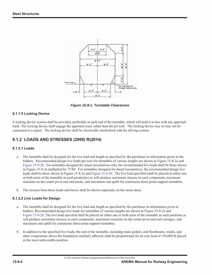
Steel Structures
© 2015, American Railway Engineering and Maintenance-of-Way Association
15-8-4 AREMA Manual for Railway Engineering
8.1.1.5 Locking Device
A locking device system shall be provided, preferably at each end of the turntable, which will hold it in line with any approachtrack. The locking device shall engage the approach track rather than the pit wall. The locking device may or may not be connected to a signal. The locking device shall be electrically interlocked with the driving system.
8.1.2 LOADS AND STRESSES (2009) R(2014)
8.1.2.1 Loads
a. The turntable shall be designed for the live load and length as specified by the purchaser in information given to the bidders. Recommended design live loads per axle for turntables of various lengths are shown in Figure 15-8-2a and Figure 15-8-2b. For turntables designed for steam locomotives only, the recommended live loads shall be those shown in Figure 15-8-2a multiplied by 72/80. For turntables designed for diesel locomotives, the recommended design live loads shall be those shown in Figure 15-8-2a and Figure 15-8-2b. The live load specified shall be placed on either one or both arms of the turntable in such position(s) as will produce maximum stresses in each component, maximum reactions on the center pivot and end trucks, and maximum end uplift for continuous three-point-support turntables.
b. The stresses from these loads and forces shall be shown separately on the stress sheet.
8.1.2.2 Live Loads for Design
a. The turntable shall be designed for the live load and length as specified by the purchaser in information given to bidders. Recommended design live loads for turntables of various lengths are shown in Figure 15-8-2a andFigure 15-8-2b. The live load specified shall be placed on either one or both arms of the turntable in such positions as will produce maximum stresses in each component, maximum reactions on the center pivot and end carriages, and maximum end uplift for continuous three-point-support turntables.
b. In addition to the specified live loads, the end of the turntable, including main girders, end floorbeams, trucks, and other components above the foundation similarly affected, shall be proportioned for an axle load of 150,000 lb placed in the most unfavorable position.
Figure 15-8-1. Turntable Clearances

Miscellaneous
© 2015, American Railway Engineering and Maintenance-of-Way Association
AREMA Manual for Railway Engineering 15-8-5
1
3
4
c. The center pivot shall be proportioned for 125% of the specified live load and the center cross girder assembly with its connections to the main girders, down to and including the bearing of the cross girder on the top of the center casting, shall be proportioned for 175% of the specified live load.
d. In considering the loads to be turned on the table, the 150,000 lb load and the 25% and 75% additions to the live load mentioned in the preceding two paragraphs shall not be included.
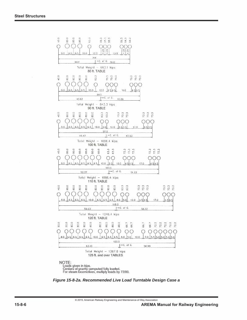
Steel Structures
© 2015, American Railway Engineering and Maintenance-of-Way Association
15-8-6 AREMA Manual for Railway Engineering
Figure 15-8-2a. Recommended Live Load Turntable Design Case a
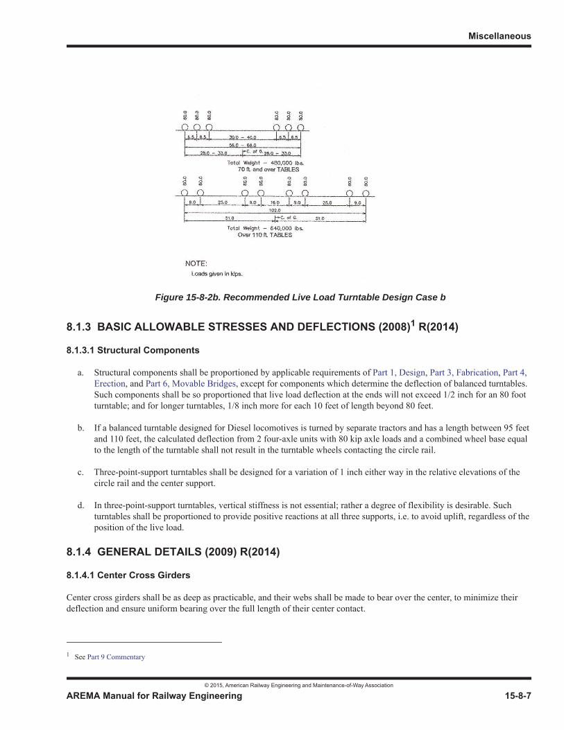
Miscellaneous
© 2015, American Railway Engineering and Maintenance-of-Way Association
AREMA Manual for Railway Engineering 15-8-7
1
3
4
8.1.3 BASIC ALLOWABLE STRESSES AND DEFLECTIONS (2008)1 R(2014)
8.1.3.1 Structural Components
a. Structural components shall be proportioned by applicable requirements of Part 1, Design, Part 3, Fabrication, Part 4, Erection, and Part 6, Movable Bridges, except for components which determine the deflection of balanced turntables. Such components shall be so proportioned that live load deflection at the ends will not exceed 1/2 inch for an 80 foot turntable; and for longer turntables, 1/8 inch more for each 10 feet of length beyond 80 feet.
b. If a balanced turntable designed for Diesel locomotives is turned by separate tractors and has a length between 95 feet and 110 feet, the calculated deflection from 2 four-axle units with 80 kip axle loads and a combined wheel base equal to the length of the turntable shall not result in the turntable wheels contacting the circle rail.
c. Three-point-support turntables shall be designed for a variation of 1 inch either way in the relative elevations of the circle rail and the center support.
d. In three-point-support turntables, vertical stiffness is not essential; rather a degree of flexibility is desirable. Such turntables shall be proportioned to provide positive reactions at all three supports, i.e. to avoid uplift, regardless of the position of the live load.
8.1.4 GENERAL DETAILS (2009) R(2014)
8.1.4.1 Center Cross Girders
Center cross girders shall be as deep as practicable, and their webs shall be made to bear over the center, to minimize their deflection and ensure uniform bearing over the full length of their center contact.
1 See Part 9 Commentary
Figure 15-8-2b. Recommended Live Load Turntable Design Case b
Steel Structures
© 2015, American Railway Engineering and Maintenance-of-Way Association
15-8-8 AREMA Manual for Railway Engineering
8.1.4.2 Bracing
a. Horizontal bracing shall be provided to permit turning the table by means of power applied at either end. Both top and bottom lateral bracing systems shall be provided where practicable. Balanced turntables shall be braced to prevent warp. Bracing shall be of such pattern that the center cross girders cannot be stressed under torque loading.
b. The minimum thickness of bracing material shall be 1/2 inch.
8.1.4.3 Footwalks
There shall be footwalks along both sides of the track. Footwalks on deck tables shall be protected by railings.
8.1.4.4 Collector Ring Support
Where feed wires of an electrically operated turntable are over the pit, a structural steel frame shall be attached to the maingirders to support the wires and the collector ring over the center.
8.1.4.5 Protection and Components
a. The center, center cross girders, and machinery shall be protected (preferably by metal housing) against the entry of water, cinders, dirt, etc.
b. The thickness of any full length top cover plate of deck girders, stringers, floorbeams, and center cross girders shall be increased 1/8 inch over the computed thickness. The section of other components subject to excessive corrosion shall be increased appropriately over the computed section.
8.1.4.6 Inspection
Turntables shall be so designed as to facilitate inspection and making repairs. Jacking brackets on the steel superstructure andfoundations in the pit paving, shall be provided for raising the turntable off the center and the circle rail. A pair of stiffenersshall be provided on the outside of each main girder near one end. Their outstanding legs shall be 3 inches apart and shall extend at least 1 inch beyond the girder flange to provide non-slip sling position for lifting the end of the turntable with a crane.
8.1.4.7 Center
a. The center pivot shall be of the disk type.
b. The point of application of the load on the pivot shall be directly over the center of the pivot. The rotating portion of thecenter pivot shall be equipped with a saddle or pin to allow longitudinal rocking of the main girders. The center cross girder assembly shall be secured to the center in such a way as to prevent the turntable from being forced off-center by a blow of locomotive wheels on the ends of the turntable rails, and where this force is resisted by a pin in a half-round bearing, the pin shall be 4 inches dia or less. The whole center, including the foundation, shall be constructed to resist any unbalanced lateral force resulting from turning the turntable.
c. The entire unit shall be as nearly dustproof and waterproof as practicable. It shall be equipped with substantial and effective lubricating devices and be so designed that it may be readily removed, taken apart, inspected, cleaned, repaired, lubricated and replaced. There shall be provision for height adjustment.
d. The disk pivot shall be one disk of phosphor bronze or be comprised of two disks, one of phosphor bronze and one of hardened steel, set in oil-tight recesses. The disks shall be so secured that sliding will take place only at the surfaces of a single disk or the contact surfaces between two disks.
e. Sliding surfaces shall be finished accurately and polished.
Miscellaneous
© 2015, American Railway Engineering and Maintenance-of-Way Association
AREMA Manual for Railway Engineering 15-8-9
1
3
4
8.1.4.8 End Trucks
a. The end trucks shall be of substantial construction. They shall be braced to hold the wheel axles in lines radiating from the center of rotation. The end trucks shall be completely assembled in correct alignment on the main girders and the correct lengths of braces determined. The braces then shall be connected. The braces shall have provisions for small length adjustments to be made, preferably by shims.
b. Bolts connecting trucks to balanced turntables shall be ASTM A325.
c. There shall be either two or four wheels at each end of the turntable. Where there are only two, they shall be placed outside the main girders and mounted in a single truck frame connected rigidly to the main girders. Where there are four wheels, they shall be mounted in pairs in separate trucks attached to the main girders so as to equalize loads transmitted to the wheels.
d. Trucks having either traction equipment built in them or separate tractors connected to them shall be adequately connected to the main girders to transmit the traction force.
e. Provisions for height adjustment shall be furnished.
f. For turntables that are turned by power to end trucks in an emergency, the truck at either end shall have sufficient power to rotate the turntable with the design load.
8.1.4.9 Wheels and Axles
a. Wheels shall be AAR multiple-wear wrought steel wheels or equal, of as large diameter as practicable, and shall not be conical. Treads shall not be flanged and the webs should be straight. Wheels shall be bored for tight fit and mounted on steel axles under heavy pressure. In addition, wheels used as drivers shall be keyed to the axles.
b. Wheel material shall conform to ASTM A504, Class C. The rims only shall be heat treated. Axle material shall conform to ASTM A236, Class G.
8.1.4.10 Bearings
a. These provisions cover the following types of axle bearings:
(1) Journal Bearings with Boxes (Old Construction)
(2) Roller Bearings (New, Rebuilt and Old Construction)
b. It is recommended that roller bearings be installed on newly constructed and rebuilt turntables.
c. It is recommended that balanced beam tables be converted during rebuilding to three-point bearing turntables using redesigned trucks.
d. Bearing boxes for journal bearings shall be of cast or rolled steel with removable phosphor bronze bushings or bearings. Other suitable types of bearing material may be specified.
e. Bearing boxes for journal bearings shall be compact, with lids which can be opened readily, and of such construction as to facilitate effective lubrication and to exclude water and dirt.
f. Bearing boxes of continuous three-point-bearing turntables shall be preferably equipped with roller bearings.

Steel Structures
© 2015, American Railway Engineering and Maintenance-of-Way Association
15-8-10 AREMA Manual for Railway Engineering
8.1.4.11 Brakes
A braking system shall be installed on the end trucks, with controls located in the operator’s house.
8.1.4.12 Circle Rail
a. The circle rail shall be of a section not less than the heaviest standard rail used by the purchaser and preferably not less than 132 lb per yd.
b. Provisions shall be made for adjustment of the elevation and the radius of the circle rail and for drainage.
c. All or most of the joints in the circle rail shall preferably be butt welded. Where bolted rail joints are used, they shall not interfere with rail anchorage. The top of the circle rail shall be in a horizontal plane.
d. The circle rail shall preferably be supported on steel beams embedded in the concrete foundation, or on bearing plates not less than 2 inches thick set directly on the concrete foundation. Where timber ties are used for supporting circle rails, they shall be treated hardwood, sized to the same dimensions, and held in position while the concrete is being placed. The circle rail shall be securely anchored to its support to hold it in alignment and to prevent creeping.
e. Circle rail shall be set level within 1/16 inch, truly circular and concentric with the turntable center within +/- 1/8 inch.
8.1.4.13 Radial Tracks
a. A track layout with tangents extending from face of pit wall a distance at least equal to the locomotive wheel base is desirable. (Anything less will result in side kick at the end of the table.)
b. Radial track rails ending at the circle wall shall not be less than 39 feet long. The radial tracks shall be box anchored for a distance of 200 feet extended outward from the pit wall to prevent longitudinal movement.
c. The top of rails of radial tracks shall be at the same elevation as the top of rails on ends of turntable, with the end truckwheels bearing. The ends of rails in radial tracks shall be held securely in line and elevation. Where wood supports are used over the circle wall under ends of radial tracks, adequate steel bearing plates shall be provided.
d. There shall be 3/4 inch clearance between the ends of the radial track rails and rails on turntable.
8.1.4.14 Rails on the Turntable
a. The rails on turntable shall be anchored securely in line and elevation and anchored to prevent longitudinal movement. The purchaser’s heaviest standard rail and steel tie plates may be used throughout, except at ends of table where there should be larger steel bearing plates with sufficient depth to prevent bending.
b. Rails at ends of turntables shall preferably be full length.
8.1.4.15 Pads
Consideration shall be given to the use of pads at locations subject to impact loads, to improve rail bearing conditions for railson the turntable, approach track rails, and circle rail.
8.1.4.16 Pit
a. The bottom of turntable pit should be paved. Ample clearance for snow shall be provided between turntable steelwork and paving. Suitable pit drainage shall be provided, and where conditions warrant there shall be an adequate drainage system behind the circle wall. An inspection pit shall be provided in the circle wall, of sufficient size to permit removal of a truck.
b. There shall be a clearance of not more than 3 inches between the circle wall and the ends of the turntable.
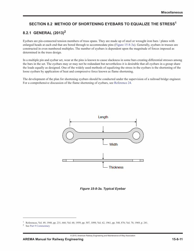
Miscellaneous
© 2015, American Railway Engineering and Maintenance-of-Way Association
AREMA Manual for Railway Engineering 15-8-11
1
3
4
SECTION 8.2 METHOD OF SHORTENING EYEBARS TO EQUALIZE THE STRESS1
8.2.1 GENERAL (2013)2
Eyebars are pin-connected tension members of truss spans. They are made up of steel or wrought iron bars / plates with enlarged heads at each end that are bored through to accommodate pins (Figure 15-8-3a). Generally, eyebars in trusses are constructed in even numbered multiples. The number of eyebars is dependent upon the magnitude of forces imposed as determined in the truss design.
In a multiple pin and eyebar set, wear at the pins is known to cause slackness in some bars creating differential stresses amongthe bars in the set. The eyebars may or may not be redundant but nevertheless it is desirable that all eyebars in a group sharethe loads equally as designed. One of the widely used methods of equalizing the stress in the eyebars is the shortening of the loose eyebars by application of heat and compressive force known as flame shortening.
The development of the plan for shortening eyebars should be conducted under the supervision of a railroad bridge engineer. For a comprehensive discussion of the flame shortening of eyebars, see Reference 24.
1 References, Vol. 49, 1948, pp. 231, 666; Vol. 60, 1959, pp. 507, 1098; Vol. 62, 1961, pp. 548, 876; Vol. 70, 1969, p. 241.2 See Part 9 Commentary
Figure 15-8-3a. Typical Eyebar
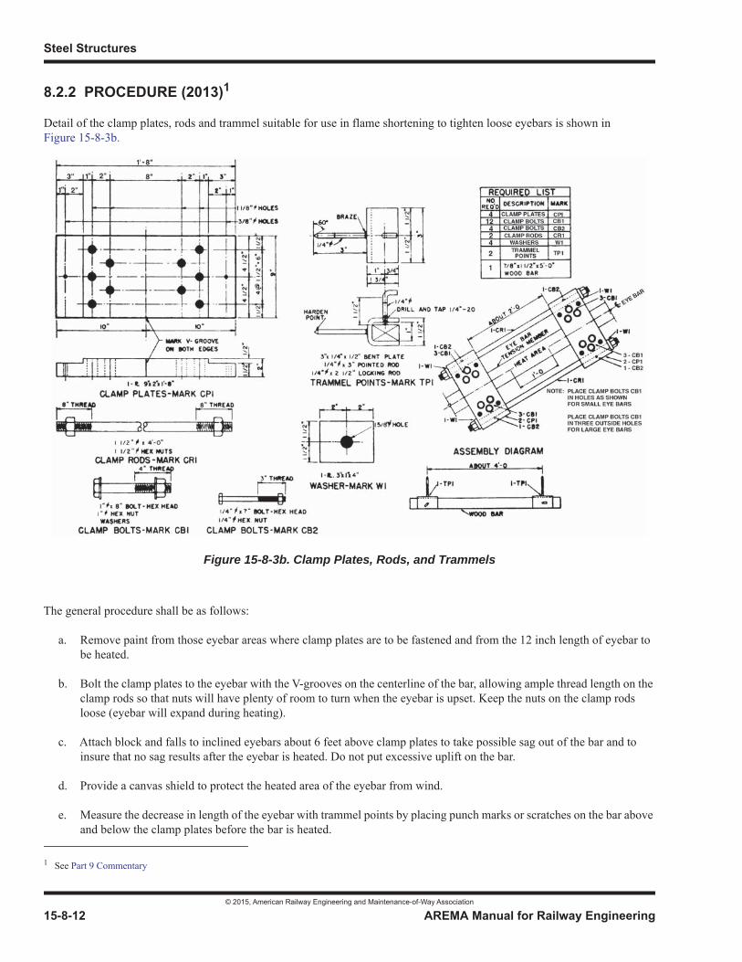
Steel Structures
© 2015, American Railway Engineering and Maintenance-of-Way Association
15-8-12 AREMA Manual for Railway Engineering
8.2.2 PROCEDURE (2013)1
Detail of the clamp plates, rods and trammel suitable for use in flame shortening to tighten loose eyebars is shown in Figure 15-8-3b.
The general procedure shall be as follows:
a. Remove paint from those eyebar areas where clamp plates are to be fastened and from the 12 inch length of eyebar to be heated.
b. Bolt the clamp plates to the eyebar with the V-grooves on the centerline of the bar, allowing ample thread length on the clamp rods so that nuts will have plenty of room to turn when the eyebar is upset. Keep the nuts on the clamp rods loose (eyebar will expand during heating).
c. Attach block and falls to inclined eyebars about 6 feet above clamp plates to take possible sag out of the bar and to insure that no sag results after the eyebar is heated. Do not put excessive uplift on the bar.
d. Provide a canvas shield to protect the heated area of the eyebar from wind.
e. Measure the decrease in length of the eyebar with trammel points by placing punch marks or scratches on the bar above and below the clamp plates before the bar is heated.
1 See Part 9 Commentary
Figure 15-8-3b. Clamp Plates, Rods, and Trammels
Miscellaneous
© 2015, American Railway Engineering and Maintenance-of-Way Association
AREMA Manual for Railway Engineering 15-8-13
1
3
4
f. Check the train traffic schedule and allow about 1 hr between trains for heating, upsetting and cooling of the eyebar.
g. Unless a lower temperature is specified by the Engineer, heat both sides of the bar to a temperature of 1,300 to 1,400 degrees F for a length of 12 inches midway between the upper and lower clamp plates with two torches using heating tips. These temperatures are not recommended for use with quenched and tempered steels. Apply the heat uniformly on both sides of the bar, which can be done by moving the torches in unison as the heating progresses.
h. Measure the temperature of the heated area with a non-contact thermometer or temperature sensing crayons.
i. When the 12 inches area is fully heated, tighten nuts on the clamp rods simultaneously and upsetting the heated area a very small amount. Take considerable care, especially on large eyebars, that the interior of the bar is fully heated. It is essential that nuts on both clamp rods are tightened the same amount. By a side push on the eyebar close to the head, it can be determined whether the heads are tight against the pins.
j. Kinking of the heated portion of the eyebar can be held to a minimum if the reduction in length is kept below 1/4 inch for each heating. A maximum of two heatings, or 1/2 inch total reduction, should be allowed at any one location on the eyebar. If more reduction is needed, move to a different location on the eyebar, preferably several feet away from the first location.
k. If the eyebar shows a tendency to buckle or delaminate, eyebar shortening shall stop. The buckling or delamination may be caused by attempting too much reduction in one heating or by trying to upset the eyebar before the correct temperature is reached. To straighten a buckled eyebar, place a 2 or 3 foot length of 8 inch steel channel on each side of the bar and cinch with heavy C clamps, striking the channel with a maul if necessary.
l. Where it is desired to keep initial or dead load eyebar stress low, reduce the amount of heat applied and keep a 3 or 4 inch length of bar in the middle of the 12 inch heated area at a temperature specified in Article 8.2.1(g) for 3 or 4 minutes. This short section of heated bar allows elongation in this area while the remainder of the heated area is cooling and contracting.
Where it is necessary to reduce initial or dead load stress in an eyebar after adjustment has been made and the eyebar has fully cooled, heat a shorter length of the eyebar to the temperature specified in Article 8.2.1(g) with clamps still in place and nuts on the clamp rods loose. The weight of lower portion of eyebar or pull on the pins when the eyebar is hot will again lengthen it and then cooling will place a smaller initial tension in the bar.
m. The upset eyebar should cool to ambient temperature gradually and unassisted. If necessary for passage of trains, the eyebar may be spray cooled with water after its temperature falls below 600 degrees F.
n. Traffic may be resumed over the bridge after the heated eyebar area has cooled to 300 degrees F.
o. Approximate dead load stress may be determined by measuring the fundamental flexural natural frequency of vibration of the bar, about its minor axis, and using this to obtain the stress F from either the chart or the formula given in Figure 15-8-4. Note that this figure is generally conservative. The approximated stress will be higher than the actual stress especially if the eyebar length is taken to be the distance between pin centers, but it can also be very inaccurate (see Commentary).
p. The natural frequency of vibration of the eyebar can be measured in the following manner:
(1) Remove clamp plates and bolts.
(2) Mount a sheet of paper or cardboard to a small piece of wood clamped to the edge of the eyebar.
(3) Place the bar in vibration about its weak axis.
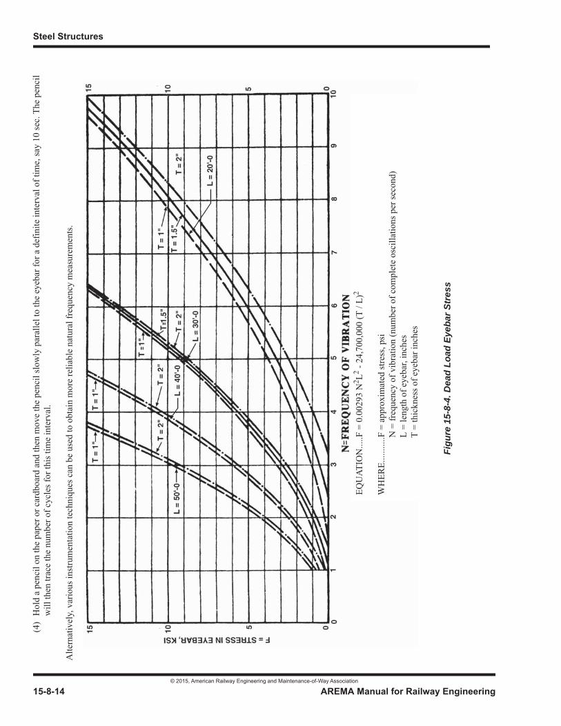
Steel Structures
© 2015, American Railway Engineering and Maintenance-of-Way Association
15-8-14 AREMA Manual for Railway Engineering
(4)
Hol
d a
penc
il on
the
pape
r or c
ardb
oard
and
then
mov
e th
e pe
ncil
slow
ly p
aral
lel t
o th
e ey
ebar
for a
def
inite
inte
rval
of t
ime,
say
10 se
c. T
he p
enci
l w
ill th
en tr
ace
the
num
ber o
f cyc
les f
or th
is ti
me
inte
rval
.
Alte
rnat
ivel
y, v
ario
us in
stru
men
tatio
n te
chni
ques
can
be
used
to o
btai
n m
ore
relia
ble
natu
ral f
requ
ency
mea
sure
men
ts.
Figu
re 1
5-8-
4. D
ead
Load
Eye
bar S
tres
s
EQU
ATIO
N...
..F =
0.0
0293
N2 L2 -
24,7
00,0
00 (T
/ L)
2
WH
ERE.
......
....F
= a
ppro
xim
ated
stre
ss, p
si
N
= fr
eque
ncy
of v
ibra
tion
(num
ber o
f com
plet
e os
cilla
tions
per
seco
nd)
L =
leng
th o
f eye
bar,
inch
es
T
= th
ickn
ess o
f eye
bar i
nche
s

Miscellaneous
© 2015, American Railway Engineering and Maintenance-of-Way Association
AREMA Manual for Railway Engineering 15-8-15
1
3
4
SECTION 8.3 ANCHORAGE OF DECKS AND RAILS ON STEEL BRIDGES1
8.3.1 FOREWORD (2010)2
a. In the absence of definitive data, there is no satisfactory way to predict behavior of rail on bridges under the influence of temperature changes, braking and traction of trains, and creep. Recommendations which follow are based on experience and research work done by the Transportation Technology Center, Inc. and the UIC (International Union of Railways) (Reference 2, 3, 64, 67, and 84).
b. Effectiveness of deck and rail anchorage systems on bridges is dependent upon proper anchorage and maintenance of track on the roadbed approaches.
8.3.2 ANCHORAGE OF DECKS TO BRIDGE SPANS (2012)3
8.3.2.1 Open Deck Bridges
a. Ties shall be anchored to bridge spans to control lateral, vertical and longitudinal movement. Each anchorage shall consist of two fasteners, each equivalent to a 3/4 inch dia bolt.
(1) On spans where rivot or bolt heads protrude into the ties, or other spans where the ties are fixed in longitudinal position, maximum longitudinal spacing of such anchorages shall be at every 4th tie, but not to exceed 4’-8” centers.
(2) On spans with a smooth tie-to-structure interface, consideration should be given to reducing the spacing of anchorages specified in paragraph (1) above.
b. Bolts fastening timber ties to open deck bridges shall preferably use a fastening system with a method to prevent bolt loosening. Such methods might include the use of double nuts, threaded fastener adhesive, locking clips, locking nuts, as well as combinations thereof. Consideration should be given to the possible need to adjust or tighten the fasteners to account for settling or shrinkage of the deck ties.
c. For spans exceeding 300 feet see Articles 1.2.13 and 8.3.4.2.
d. Where hook bolts are used for anchorage of ties, the Engineer may also require that ties be dapped to fit top flanges of girders or stringers or that other suitable lateral restraining devices be installed. Such tie daps shall not be less than 1/2 inch deep nor more than 1/2 inch wider than girder or stringer flange.
e. A spacer timber of section not less than 4 8 nominal or a metal spacer plate shall be placed on the deck outside of each rail and secured to each tie with lag bolts or drive spikes of not less than 5/8 inch dia.
8.3.2.2 Ballasted Deck Bridges
a. Timber ballasted decks and precast concrete slab decks shall be anchored to bridge spans with fasteners having total capacity equivalent to that specified for open decks.
b. Cast-in-place concrete decks shall be anchored to steel spans either by shear connectors or by making the bottom of the concrete slab flush with the bottom surface of top flanges of girders or stringers.
1 References, Vol. 76, 1975, p. 338; Vol. 77, 1976, p. 250; Vol. 79, 1978, p. 49.2 See Part 9 Commentary3 See Part 9 Commentary
Steel Structures
© 2015, American Railway Engineering and Maintenance-of-Way Association
15-8-16 AREMA Manual for Railway Engineering
8.3.3 ANCHORAGE OF RAIL (2011)1
8.3.3.1 Longitudinal Anchorage of Rail on Bridge Approaches
On roadbed approaches to bridges of length over 50 feet, rail shall be box anchored longitudinally at each tie a distance of 200feet unless otherwise specified by the Engineer.
8.3.3.2 Lateral and Vertical Rail Anchorage
Tie plates and spikes manufactured and installed in accordance with the Company’s standard specifications shall be considered adequate as lateral and vertical anchorage of rails to timber ties.
8.3.3.3 Anchorage of Rail to Concrete Slabs, Concrete Ties, or Directly to Steel Spans
Such fastening systems are special applications and shall be approved by the Engineer.
8.3.3.4 Longitudinal Anchorage of Conventional Jointed Rail
a. On open deck bridges, rail anchors shall be installed as specified by the Engineer.
b. On ballasted deck bridges, rail anchors shall be installed in accordance with the Company’s standard specifications for track not on bridges unless otherwise specified by the Engineer.
8.3.3.5 Anchorage Requirements for Continuous Welded Rail (CWR) without Expansion Joints on Open Deck Bridges
For bridges with CWR not longitudinally anchored, the provisions of 8.3.3.5.1 shall apply. For bridges with CWR longitudinally anchored, the provisions of 8.3.3.5.2 shall apply (See Commentary).
8.3.3.5.1 Continuous Welded Rail without Expansion Joints on Open Deck Bridges, Rail Not Longitudinally Anchored
Rail may be unanchored on bridges having a total length of 400 feet or less on tangent track and on curved track with curvatureless than 1 degree, or as directed by the Engineer, provided there is a rail flaw management program in place. Unanchored railshall not be placed on individual spans exceeding 300 feet unless rail expansion joints are installed (See Articles 1.2.13 and 8.3.4.2).
8.3.3.5.2 Continuous Welded Rail without Expansion Joints on Open Deck Bridges, Rail Longitudinally Anchored
a. For individual spans of 100 feet or less, rail anchors shall be applied throughout the span at all ties anchored to bridge spans (See Article 8.3.2.1 and Commentary).
b. For individual spans exceeding 100 feet, rail anchors shall be applied at ties anchored to the span in the first 100 feet from the fixed end (See Article 8.3.2.1 and Commentary).
c. Rail anchors and hook bolts or similar fastening of the deck to spans should be placed in accordance with Article 8.3.2.1 (See Commentary).
d. Bolted joints connecting strings of continuous welded rail shall not be located on bridges nor on roadbed approaches within 200 feet of the ends of bridges.
1 See Part 9 Commentary
Miscellaneous
© 2015, American Railway Engineering and Maintenance-of-Way Association
AREMA Manual for Railway Engineering 15-8-17
1
3
4
e. Forces in continuous welded rail may be computed from the following equations:
R.F. =
where:
8.3.3.6 Longitudinal Anchorage of Continuous Welded Rail without Expansion Joints on Ballasted Deck Bridges
Rail anchors shall be installed in accordance with the Company’s standard specifications for track not on bridges unless otherwise specified by the Engineer.
8.3.3.7 Longitudinal Anchorage of Continuous Welded Rail with Expansion Joints
a. Rail anchors shall be applied to secure fixed parts of rail expansion joints.
b. Rail anchors shall be applied at the center of rail strings having movable parts of rail expansion joints at the ends.
8.3.4 RAIL EXPANSION JOINTS (2012)1
Movement of rail due to changes in temperature or to train action sometimes produces adverse effects. The magnitudes of the movement and of resulting forces are difficult to forecast. Rail expansion joints may be used in order to reduce the likelihoodof rail breakage, to relieve rail radial forces where they cannot feasibly be resisted, and to facilitate track maintenance wheretrack and fastenings must be disturbed.
8.3.4.1 Movable Bridge Spans
a. In addition to rail joints that provide for expansion and contraction of the movable span and its rails, consideration shall be given to placing one pair of rail expansion joints immediately off each end of the span.
b. Deck and rails shall be anchored to the movable span as specified by the Engineer to prevent their displacement during opening and closing of the span.
8.3.4.2 Long Individual Bridge Spans
For individual simple bridge spans of 300 feet or greater, rail expansion joints shall preferably be installed at or near the expansion end of the span, as specified by the Engineer or, alternatively, rail expansion joints may be installed as specified inArticle 8.3.4.4. When rail expansion joints are used at the expansion end of long bridge spans, rail anchors may be installed near the fixed bearings to control creep.
I.F. = internal force in 2 rails, lb; compression for temperature rise, tension for temperature fallR.F. = radial force in 2 rails, lb per foot of bridge; acting toward outside of curve for temperature rise, toward
inside for temperature fallW = weight of one rail, lb per ydT = temperature change, degrees FD = degree of curvature
1 See Part 9 Commentary
I.F. = 38 WT
WDT150
-------------
Steel Structures
© 2015, American Railway Engineering and Maintenance-of-Way Association
15-8-18 AREMA Manual for Railway Engineering
8.3.4.3 Open Deck Bridges on Curves with Continuous Welded Rail
Rail expansion joints shall preferably be used for each bridge having total length greater than 50 feet located on curve exceeding 2 degrees. Where feasible, joint location should be off the curve.
8.3.4.4 Number and Positioning of Rail Expansion Joints on Bridges with Continuous Welded Rail
a. Rail expansion joints shall be used in pairs, which shall be installed closely or directly opposite to each other, depending on type of joint used.
b. Where a single pair of joints are used, the preferred location is at a minimum of 20 feet from the back of the abutment, where possible.
c. Where two pairs of joints are used, they shall preferably be located near the center of the bridge.
d. Where an even number of pairs of expansion joints is used greater than two pairs, they shall preferably be placed in groups of two pairs, with the fixed parts of one pair connected to fixed parts of the other pair.
e. Where an odd number of pairs of expansion joints is used, the odd pair shall preferably be at one end of bridge, and either entirely on or off the bridge. In absence of other controlling conditions, the odd pair shall preferably be at the lower end of a bridge on grade and the remaining pairs shall be placed as in paragraph d.
f. The spacing and design of joints shall be such that the maximum length L, in feet of rail, causing movement through each joint shall be as follows, except that L shall not exceed 1,500 feet.
EQ 1
where:
For recommended values, formula EQ 1 reduces to
EQ 2
or
J = EQ 3
g. Rail expansion joints shall be assembled in such a manner that they are at the approximate midpoint of the range of movement at a temperature midway between expected extremes.
h. Design and details of rail expansion joints shall be such as to minimize resistance to expansion and contraction.
e = coefficient of rail thermal expansion = 0.0000066T = temperature range, deg F (140 degrees recommended in the absence of a substantiated value)J = total permissible range of movement in joints, inch
K1 = creep allowance, inch (3 inches recommended in absence of a substantiated value)
K2 = safety factor (1.5 recommended)
eLT = J K1–
12K2----------------------
L = J 3 60–
L60------ 3+
Miscellaneous
© 2015, American Railway Engineering and Maintenance-of-Way Association
AREMA Manual for Railway Engineering 15-8-19
1
3
4
8.3.4.5 Rail Expansion Joints in Track with Bolted Rail Joints
Where rail expansion joints are used in track having bolted rail joints, consideration shall be given to the possibility and consequences of bolted joint failure and excessive longitudinal movement of rail through the expansion joint. All such installations shall require approval by the Engineer.
8.3.5 MAINTENANCE OF BRIDGES WITH CONTINUOUS WELDED RAIL (1983) R(2012)
a. Suitable measures shall be taken to prevent buckling of track or rails during maintenance operations. The most favorable rail temperatures for such work are those below that of the rail when it was laid. The probability of rail compression resulting from creep and other causes shall be considered.
b. On curved track, the effect of radial forces shall be considered and measures taken to hold the track in line during maintenance operations. Work shall not be done during periods of extreme high or low temperatures.
c. Maintenance operations involving removal of fastenings of rail to ties, or ties to bridge steel shall be carried out in short sections; and, where practicable, on alternate ties in a first phase and on the remaining ties in a second phase.
SECTION 8.4 UNLOADING PITS1
8.4.1 SCOPE AND PURPOSE (2013)2
This section gives recommended practice for the design of small undertrack structures for handling of materials unloaded through the bottom of a railroad car. Representative details and data are included to assist the industry owner in preparing plans for submittal to railroads operating on tracks involved and to facilitate a railroad’s consideration of such submissions.
8.4.2 GENERAL (2013)
a. Design of supporting beams for unloading pits shall conform to the requirements of Part 1, Design, Part 3, Fabricationand Part 4, Erection, except as modified herein.
b. Design of the pit structure shall conform to the requirements of Chapter 8, Concrete Structures and Foundations.
c. Typical configurations are shown in Figure 15-8-5 and Figure 15-8-6 and design criteria are listed in Article 8.4.3 and Article 8.4.4.
d. Track running rails shall be attached directly, without ties, to supporting beams except in the case of very short spans where the running rails may be adequate to carry wheel loads without supporting beams.
8.4.3 OPERATING LIMITATIONS (2013)
a. This section applies to pits located on tracks where speed does not exceed 10 mph.
b. Where train speed exceeds 10 mph, the structure shall be designed as a bridge.
1 References, Vol. 78, 1977, p. 90.2 See Part 9 Commentary

Steel Structures
© 2015, American Railway Engineering and Maintenance-of-Way Association
15-8-20 AREMA Manual for Railway Engineering
8.4.4 LOADS (1993) R(2012)
a. Supporting beams shall be proportioned for the sum of the following loads:
(1) Dead load.
(2) Live load.
(3) Impact load.
b. The pit structure shall be proportioned for the sum of the following loads:
(1) Dead load.
(2) Live load, without impact load.
(3) Horizontal earth pressure.
(4) Horizontal live load surcharge.
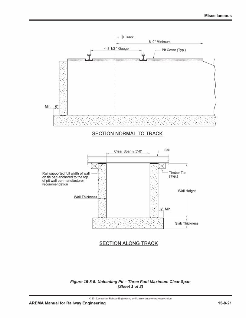
Miscellaneous
© 2015, American Railway Engineering and Maintenance-of-Way Association
AREMA Manual for Railway Engineering 15-8-21
1
3
4
Figure 15-8-5. Unloading Pit – Three Foot Maximum Clear Span(Sheet 1 of 2)
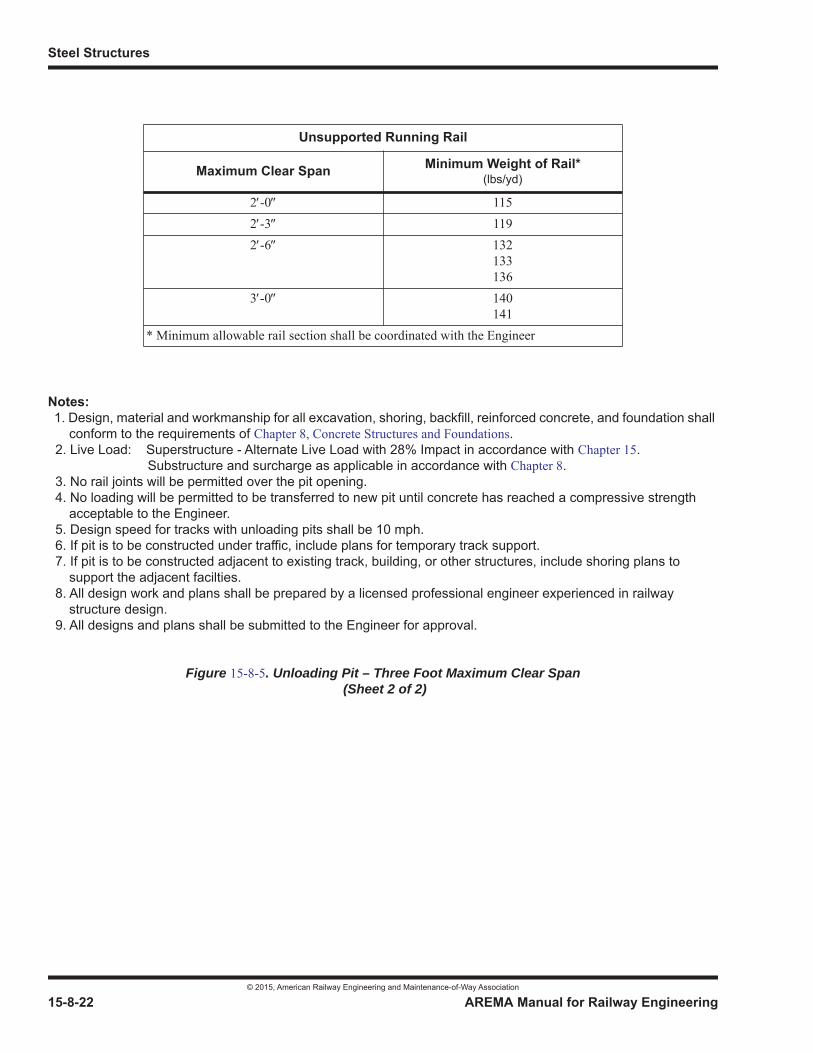
Steel Structures
© 2015, American Railway Engineering and Maintenance-of-Way Association
15-8-22 AREMA Manual for Railway Engineering
Notes: 1. Design, material and workmanship for all excavation, shoring, backfill, reinforced concrete, and foundation shall
conform to the requirements of Chapter 8, Concrete Structures and Foundations. 2. Live Load: Superstructure - Alternate Live Load with 28% Impact in accordance with Chapter 15. Substructure and surcharge as applicable in accordance with Chapter 8. 3. No rail joints will be permitted over the pit opening. 4. No loading will be permitted to be transferred to new pit until concrete has reached a compressive strength
acceptable to the Engineer. 5. Design speed for tracks with unloading pits shall be 10 mph. 6. If pit is to be constructed under traffic, include plans for temporary track support. 7. If pit is to be constructed adjacent to existing track, building, or other structures, include shoring plans to
support the adjacent facilties. 8. All design work and plans shall be prepared by a licensed professional engineer experienced in railway
structure design. 9. All designs and plans shall be submitted to the Engineer for approval.
Figure 15-8-5. Unloading Pit – Three Foot Maximum Clear Span (Sheet 2 of 2)
Unsupported Running Rail
Maximum Clear Span Minimum Weight of Rail*(lbs/yd)
2 -0 1152 -3 1192 -6 132
133136
3 -0 140141
* Minimum allowable rail section shall be coordinated with the Engineer

Miscellaneous
© 2015, American Railway Engineering and Maintenance-of-Way Association
AREMA Manual for Railway Engineering 15-8-23
Figu
re 1
5-8-
6. U
nloa
ding
Pit
– Fi
fteen
Foo
t Max
imum
Spa
n (S
heet
1 o
f 3)

Steel Structures
© 2015, American Railway Engineering and Maintenance-of-Way Association
15-8-24 AREMA Manual for Railway Engineering
Figure 15-8-6. Unloading Pit – Fifteen Foot Maximum Span (Sheet 2 of 3)
Table of Beam Requirements
SpanFeet
RequiredWeb AreaInches2
RequiredS
Inches3Beam
Size of 1 InchBearing Plate
Inches
Width of 1/2 Inch Stiffeners
Inches
NumberInterior
Diaphram
5or less 5.0 47.9 W8 67
HP10 576 146 16
3.54 0
6 5.9 57.6 W10 88HP12 63
6 16 44 0
7 6.5 67.3 W10 88HP12 74
6 166 18
44 1
8 6.9 77.0 W12 96HP12 74
6 186 18
34 1
9 7.3 90.5 W12 106HP12 74
7 186 18
55 1
10 7.6 108.4 W12 106HP14 89
7 186 21
55 1
11 7.8 126.9 W12 106HP14 89
7 186 21
55 1
12 8.4 145.5 W12 120HP14 102
7 186 21
55 1
13 8.9 165.0 W14 132W16 100
6 217 18
55 2
14 9.4 194.0 W14 132W18 106
7 218 18
65.25 2
15 9.7 222.8 W18 119W21 101
8 189 15
5.255.25 2
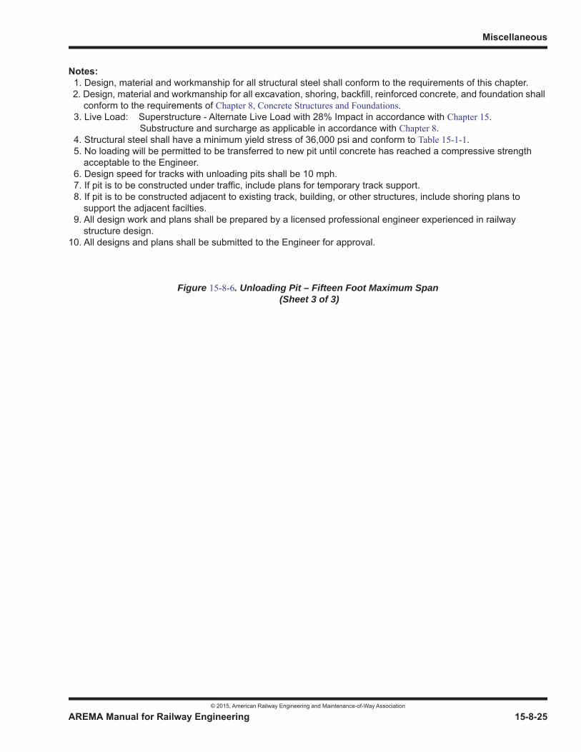
Miscellaneous
© 2015, American Railway Engineering and Maintenance-of-Way Association
AREMA Manual for Railway Engineering 15-8-25
1
3
4
Notes: 1. Design, material and workmanship for all structural steel shall conform to the requirements of this chapter. 2. Design, material and workmanship for all excavation, shoring, backfill, reinforced concrete, and foundation shall
conform to the requirements of Chapter 8, Concrete Structures and Foundations. 3. Live Load: Superstructure - Alternate Live Load with 28% Impact in accordance with Chapter 15. Substructure and surcharge as applicable in accordance with Chapter 8. 4. Structural steel shall have a minimum yield stress of 36,000 psi and conform to Table 15-1-1. 5. No loading will be permitted to be transferred to new pit until concrete has reached a compressive strength
acceptable to the Engineer. 6. Design speed for tracks with unloading pits shall be 10 mph. 7. If pit is to be constructed under traffic, include plans for temporary track support. 8. If pit is to be constructed adjacent to existing track, building, or other structures, include shoring plans to
support the adjacent facilties. 9. All design work and plans shall be prepared by a licensed professional engineer experienced in railway
structure design.10. All designs and plans shall be submitted to the Engineer for approval.
Figure 15-8-6. Unloading Pit – Fifteen Foot Maximum Span (Sheet 3 of 3)
Steel Structures
© 2015, American Railway Engineering and Maintenance-of-Way Association
15-8-26 AREMA Manual for Railway Engineering
8.4.5 UNSUPPORTED RUNNING RAIL (2013)
a. The maximum clear span length for unloading pits without supporting beams shall be as shown in Figure 15-8-5.
b. The design span shall be taken as clear span plus 6 inches.
c. No running rail joints shall be permitted over the pit.
d. The top of the concrete pit walls shall be true and level to provide full bearing for the running rails.
8.4.6 STRUCTURAL SUPPORTING BEAMS (1993)1 R(2012)
a. This article is applicable to a maximum span length of 15 feet. See Figure 15-8-6 for details. Spans longer than 15 feet shall be designed as bridges in accordance with Part 1, Design, Part 3, Fabrication and Part 4, Erection.
b. Running rails shall normally be attached to the supporting beam with pairs of 7/8 inch hook bolts spaced at 2 feet. However, where the width of flange is adequate, and provision is made for loss of section at the holes, rail clips at 2 -6centers may be used in lieu of hook bolts to attach the running rail to the supporting beam. Welding of rails to beams shall not be permitted.
c. The supporting beam shall be provided with end bearing stiffener plates fillet welded to the web and ground to bear against both top and bottom flanges or welded with full penetration groove welds at top and bottom flanges.
d. Beams shall be provided with masonry plates between beams and concrete pit walls. Beams shall be welded to the masonry plates. Should the owner desire, sole plates can be provided between beam and masonry plate. The sole plate shall be welded to the beam flange and may be beveled on the bottom surface from the inside edge to within 1 inch of the center line of bearing. Elastomeric bearing pads 1/4 inch thick under masonry plates are recommended.
e. Two anchor bolts for each masonry plate shall be provided. Anchor bolts shall be 1 inch minimum diameter, swedged, and shall extend 12 inches into the masonry. Anchor bolts may be preset, or drilled and grouted into place after steel is erected.
f. Interior diaphragms shall be used at a maximum of 6 foot centers. Diaphragms shall be channel sections as deep as the beam will allow.
g. End diaphragms of the same section as the interior diaphragms shall be connected to end stiffener plates at each end of the beam. Where ends of the beam are to be encased in concrete, end diaphragms may be omitted.
8.4.7 CONCRETE PIT (2013)2
a. A minimum of 2 inches shall be provided from edge of bearing plate to face of pit wall.
b. The design and details of the pit structure shall conform to the requirements of Chapter 8.
8.4.8 CONSTRUCTION DRAWINGS (2013)
a. Figure 15-8-5 and Figure 15-8-6 are intended as a guide in preparing construction drawings and are not themselves construction drawings. Where these details are not considered applicable, alternate details may be submitted. Note that beams shown in table of beam requirements are applicable for details and allowable loads shown. Where additional holes are made in the flange or web for bolted connections or rail clips, or where there is additional dead weight of
1 See Part 9 Commentary2 See Part 9 Commentary

Miscellaneous
© 2015, American Railway Engineering and Maintenance-of-Way Association
AREMA Manual for Railway Engineering 15-8-27
1
3
4
mechanical equipment or unloading devices, design of beams must be reviewed. A complete construction drawing should show the following:
(1) Location of structure relative to existing tracks.
(2) Plan, elevation, and sections.
(3) Complete details including dimensions, reinforcing, beam details, and cover details.
(4) Where pit is to be constructed under traffic, provisions for temporary support of the track shall be included.
(5) Where pit is located adjacent to an operating track, provisions for sheeting to support the operating track during construction shall be included.
b. Complete construction plans shall be submitted to the Engineer for approval prior to initiation of construction. Only approved plans shall be used for construction.
8.4.9 INDUSTRY OWNER’S RESPONSIBILITIES (1983) R(2012)
a. The owner shall contact the Company in advance to determine the acceptability of the chosen location with respect to movement of rail traffic and to determine requirements for construction, including but not limited to need for falsework to maintain rail traffic, need for sheeting and shoring to protect rail traffic on adjacent tracks and variations in specified loadings (and impact).
b. The owner shall make adequate provision for disposal of drainage water.
c. The owner shall obtain permits as required.
SECTION 8.5 WALKWAYS, HANDRAILS, AND FIXED LADDERS ON BRIDGES
8.5.1 LOCATIONS (2014)
Those bridges on which walkways, handrails, and fixed ladders are required will be designated by the Engineer.
8.5.2 CLEARANCES AND MINIMUM DIMENSIONS (2014)1
Clearances shall not be less than specified in Part 1, Design, Article 1.2.6. A guide to legal requirements in the various states may be found in Chapter 28, Clearances, Section 3.6, Legal Clearance Requirements.
8.5.2.1 Handrails
a. In through structures, handrail need not provide more clearance than the structural members.
b. Top of handrail shall be not less than 3 -6 above surface of walkways. An intermediate rail, or rails, shall be provided, with clear space between rails, or between rail and top of walkways, not to exceed 1 -9 .
c. The ends of rails shall not overhang terminal posts except where such overhang does not constitute a projection hazard.
1 See Part 9 Commentary

Steel Structures
© 2015, American Railway Engineering and Maintenance-of-Way Association
15-8-28 AREMA Manual for Railway Engineering
8.5.2.2 Walkways
a. In general, walkways shall not be less than 2 -0 wide and shall extend to the inner face of the handrail. On ballasted deck bridges the ballast may be used as the walkway, or a separate walkway may be provided. On open deck bridges, not more than 2 inches gap shall be allowed between the line of the ends of ties and edge of walkways.
b. On bridges with two or more tracks, walkway may be located between the tracks, without handrails.
c. Structural members (such as floorbeam brackets) shall not be considered an obstruction to the walkway.
d. Walkways on bridges over highways or other locations where spillage of ballast or lading is a consideration shall be solid material (i.e. not grating) and shall be provided with a curb or toe board.
8.5.2.3 Fixed Ladders
a. Fixed ladders permanently attached to the structure should, where possible, be located such that the user is outside of the railway clearance envelope when climbing the ladder.
b. In through structures, fixed ladders need not provide more clearance than the structural members.
c. Dimensions and clearances for fixed ladders shall conform to Occupational Safety and Health Administration (OSHA) regulations for General Industry. Properly anchored fall protection systems shall be applied to conform to regulations (see Commentary) governing railroad bridge workers.
8.5.3 LOADS (2014)1
8.5.3.1 Handrails
a. Each railing and its fastening shall be designed for a single load of 200 lb, applied either laterally or vertically, and at any point in the span.
b. Where steel cable is used for railing, sag at middle of any span shall not exceed 2 inches.
c. Posts shall be designed for a single load of 200 lb acting either laterally or vertically, applied at point of attachment of top railing.
8.5.3.2 Walkways
a. Walkways shall be designed to support a uniformly distributed load of not less than 85 lb per square foot.
b. The walkway deflection under a single concentrated live load of 250 lb applied at midspan, shall not exceed 1/160 of the span length.
c. Where off-track equipment may be driven across the bridge, walkways should be designed for the appropriate wheel loads. Deflection may be disregarded.
8.5.3.3 Fixed Ladders
a. Each rung of a fixed ladder shall be designed to support a single load of 300 lb applied at the center of the rung.
1 See Part 9 Commentary
Miscellaneous
© 2015, American Railway Engineering and Maintenance-of-Way Association
AREMA Manual for Railway Engineering 15-8-29
1
3
4
b. Fixed ladders and their connections shall be designed to support two loads of 300 lb each concentrated between any two adjacent attachments to the structure positioned for maximum design stress in the ladder, ladder support, and structural members.
8.5.4 MATERIALS (2014)
8.5.4.1 Stresses
Walkways, handrails, and fixed ladders may be designed for higher stresses than allowed for members subject to railroad live loading, as approved by the Engineer.
8.5.4.2 Handrails
a. Rails or posts of timber shall have minimum thickness of 2 inches nominal. Rail material shall be surfaced.
b. Rails or posts of structural steel shall have minimum thickness of 1/4 inch.
c. Cable rails shall be of minimum 3/8 inch diameter, 7-wire galvanized steel strand. Cut ends shall be suitably protected to prevent injury to personnel.
d. Posts connected to a structural member and the connection shall be designed to fail under overload without damaging the member.
8.5.4.3 Walkways
a. Walkways shall have a suitable walking surface.
b. Timber walkways material shall have a minimum nominal thickness of 2 inches, with the walking surface rough. Walkway timbers shall be fastened to each support with the equivalent of 2–20d spikes.
c. Structural steel plate used for walkway material shall have a roughened tread surface (checker plate), with a minimum thickness of 1/4 inch.
d. Metal grating used as walkway material shall be of galvanized steel or other corrosion resistant material. Fastenings shall be adequate to prevent longitudinal movement (which may result in loss of bearing).
8.5.4.4 Fixed Ladders
a. Side rails and attachment brackets shall be structural steel and have a minimum thickness of 3/8 inch.
b. Ladder rungs shall be structural steel with a minimum diameter or tread width of 3/4 inch and be corrugated, knurled, dimpled or coated with slip-resistant material.
c. Metal ladders and appurtenances shall be painted or otherwise treated to resist corrosion and rusting when location demands.
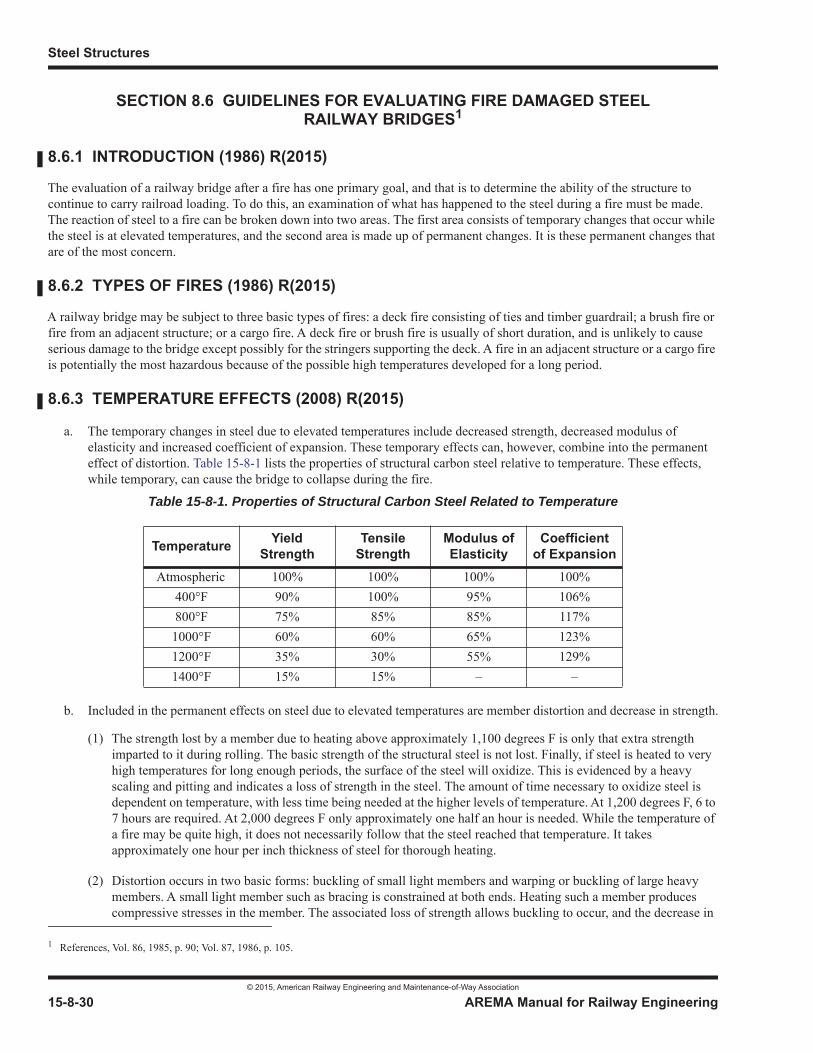
Steel Structures
© 2015, American Railway Engineering and Maintenance-of-Way Association
15-8-30 AREMA Manual for Railway Engineering
SECTION 8.6 GUIDELINES FOR EVALUATING FIRE DAMAGED STEEL RAILWAY BRIDGES1
8.6.1 INTRODUCTION (1986) R(2015)
The evaluation of a railway bridge after a fire has one primary goal, and that is to determine the ability of the structure to continue to carry railroad loading. To do this, an examination of what has happened to the steel during a fire must be made. The reaction of steel to a fire can be broken down into two areas. The first area consists of temporary changes that occur whilethe steel is at elevated temperatures, and the second area is made up of permanent changes. It is these permanent changes that are of the most concern.
8.6.2 TYPES OF FIRES (1986) R(2015)
A railway bridge may be subject to three basic types of fires: a deck fire consisting of ties and timber guardrail; a brush fire or fire from an adjacent structure; or a cargo fire. A deck fire or brush fire is usually of short duration, and is unlikely to causeserious damage to the bridge except possibly for the stringers supporting the deck. A fire in an adjacent structure or a cargo fireis potentially the most hazardous because of the possible high temperatures developed for a long period.
8.6.3 TEMPERATURE EFFECTS (2008) R(2015)
a. The temporary changes in steel due to elevated temperatures include decreased strength, decreased modulus of elasticity and increased coefficient of expansion. These temporary effects can, however, combine into the permanent effect of distortion. Table 15-8-1 lists the properties of structural carbon steel relative to temperature. These effects, while temporary, can cause the bridge to collapse during the fire.
b. Included in the permanent effects on steel due to elevated temperatures are member distortion and decrease in strength.
(1) The strength lost by a member due to heating above approximately 1,100 degrees F is only that extra strength imparted to it during rolling. The basic strength of the structural steel is not lost. Finally, if steel is heated to very high temperatures for long enough periods, the surface of the steel will oxidize. This is evidenced by a heavy scaling and pitting and indicates a loss of strength in the steel. The amount of time necessary to oxidize steel is dependent on temperature, with less time being needed at the higher levels of temperature. At 1,200 degrees F, 6 to 7 hours are required. At 2,000 degrees F only approximately one half an hour is needed. While the temperature of a fire may be quite high, it does not necessarily follow that the steel reached that temperature. It takes approximately one hour per inch thickness of steel for thorough heating.
(2) Distortion occurs in two basic forms: buckling of small light members and warping or buckling of large heavy members. A small light member such as bracing is constrained at both ends. Heating such a member produces compressive stresses in the member. The associated loss of strength allows buckling to occur, and the decrease in
1 References, Vol. 86, 1985, p. 90; Vol. 87, 1986, p. 105.
Table 15-8-1. Properties of Structural Carbon Steel Related to Temperature
Temperature YieldStrength
TensileStrength
Modulus ofElasticity
Coefficientof Expansion
Atmospheric 100% 100% 100% 100%400°F 90% 100% 95% 106%800°F 75% 85% 85% 117%1000°F 60% 60% 65% 123%1200°F 35% 30% 55% 129%1400°F 15% 15% – –

Miscellaneous
© 2015, American Railway Engineering and Maintenance-of-Way Association
AREMA Manual for Railway Engineering 15-8-31
1
3
4
elasticity makes this buckling permanent. A large heavy member such as a girder cannot be uniformly heated. This uneven heating causes warping or buckling. This same effect can cause distortion during welding and is also the principle behind flame straightening or cambering. Distortion can occur after temperatures as low as 450 degrees F and is, therefore, not a precise indication of the maximum temperature reached by the steel during a fire. When steel is heated above its transformation temperature (1,300 to 1,550 degrees F) and quickly cooled, it will lose some of its ductility. If steel is heated above approximately 1,100 degrees F and cooled slowly, it will lose part of its as-rolled strength. It is these last two changes, which are not readily discernible, that cause the most concern. However, the quick rate of cooling needed to harden steel is virtually impossible to achieve at a fire site. The use of water from a fire hose is usually insufficient to cause hardening, but may increase the distortion experienced by a member.
8.6.4 HIGH-STRENGTH STEELS (1985) R(2015)
The comments of Article 8.6.3 on the effect of temperature do not necessarily apply to high-strength steels which have achieved their strength through heat treatment. Such steels must be given individual consideration and may require laboratory study.
8.6.5 FASTENERS (1985) R(2015)
a. Fasteners, either rivets or bolts, will begin to lose their clamping force at approximately 600 degrees F. They should be carefully inspected and if there is any indication that the fasteners have been affected by the fire, they should be replaced. This is normally a simple routine, and one that should be followed to ensure long term reliability.
b. Fasteners in connections of distorted members may also be subjected to high tensile forces which can result in popped rivet heads or broken bolts. This condition may occur away from the fire zone.
c. All welds should be visually inspected for signs of distress. In some cases more sophisticated inspection may be warranted.
8.6.6 EVALUATION OF BRIDGE (1986) R(2015)
a. To evaluate a railway bridge after a fire the following data are useful:
(1) Maximum temperature reached by the steel.
(2) Length of time maximum temperature was maintained.
(3) Information on the physical condition of the steel.
(a) distortions.
(b) scaling, pitting, etc.
(c) hardness.
(4) Laboratory test results of specimens taken from structure.
b. Items 1 and 2 are usually not available, or if available are only estimates. The information in Item 3 can be obtained by an examination of the steel in the field and is the most important. Item 4 is often impractical within the time frame to restore service but may be conducted later to eliminate any doubts regarding long term service.
c. The most obvious physical change resulting from fire is distortion. While distortion may be grounds for rejection, it is not necessarily an indication of a lessening of the strength of the steel. If a member can be straightened economically, it usually can be reused. A member with only minor distortions may be usable without repair.
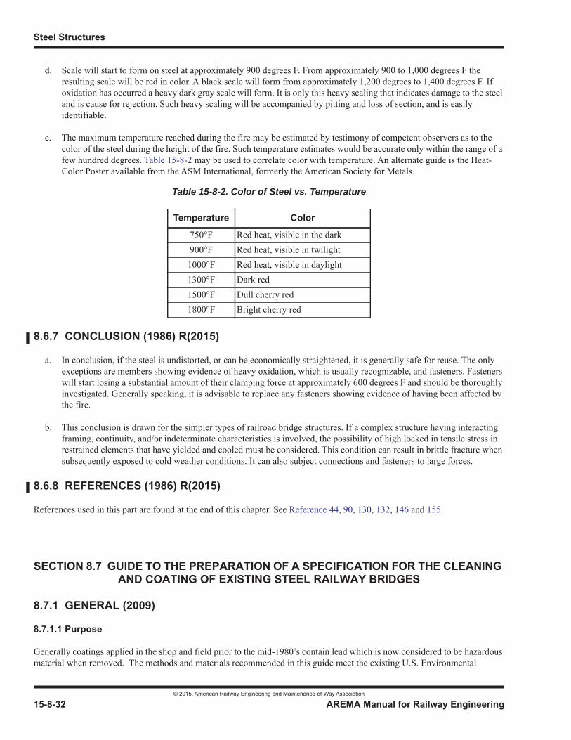
Steel Structures
© 2015, American Railway Engineering and Maintenance-of-Way Association
15-8-32 AREMA Manual for Railway Engineering
d. Scale will start to form on steel at approximately 900 degrees F. From approximately 900 to 1,000 degrees F the resulting scale will be red in color. A black scale will form from approximately 1,200 degrees to 1,400 degrees F. If oxidation has occurred a heavy dark gray scale will form. It is only this heavy scaling that indicates damage to the steel and is cause for rejection. Such heavy scaling will be accompanied by pitting and loss of section, and is easily identifiable.
e. The maximum temperature reached during the fire may be estimated by testimony of competent observers as to the color of the steel during the height of the fire. Such temperature estimates would be accurate only within the range of a few hundred degrees. Table 15-8-2 may be used to correlate color with temperature. An alternate guide is the Heat-Color Poster available from the ASM International, formerly the American Society for Metals.
8.6.7 CONCLUSION (1986) R(2015)
a. In conclusion, if the steel is undistorted, or can be economically straightened, it is generally safe for reuse. The only exceptions are members showing evidence of heavy oxidation, which is usually recognizable, and fasteners. Fasteners will start losing a substantial amount of their clamping force at approximately 600 degrees F and should be thoroughly investigated. Generally speaking, it is advisable to replace any fasteners showing evidence of having been affected by the fire.
b. This conclusion is drawn for the simpler types of railroad bridge structures. If a complex structure having interacting framing, continuity, and/or indeterminate characteristics is involved, the possibility of high locked in tensile stress in restrained elements that have yielded and cooled must be considered. This condition can result in brittle fracture when subsequently exposed to cold weather conditions. It can also subject connections and fasteners to large forces.
8.6.8 REFERENCES (1986) R(2015)
References used in this part are found at the end of this chapter. See Reference 44, 90, 130, 132, 146 and 155.
SECTION 8.7 GUIDE TO THE PREPARATION OF A SPECIFICATION FOR THE CLEANING AND COATING OF EXISTING STEEL RAILWAY BRIDGES
8.7.1 GENERAL (2009)
8.7.1.1 Purpose
Generally coatings applied in the shop and field prior to the mid-1980’s contain lead which is now considered to be hazardous material when removed. The methods and materials recommended in this guide meet the existing U.S. Environmental
Table 15-8-2. Color of Steel vs. Temperature
Temperature Color
750°F Red heat, visible in the dark900°F Red heat, visible in twilight1000°F Red heat, visible in daylight1300°F Dark red1500°F Dull cherry red1800°F Bright cherry red
Miscellaneous
© 2015, American Railway Engineering and Maintenance-of-Way Association
AREMA Manual for Railway Engineering 15-8-33
1
3
4
Protection Agency (EPA) requirements and are based on the current technology and research to produce a cost effective, environmentally acceptable steel protection system. The user of this guide is advised to consult current regulatory agency requirements governing any particular project based scope of work and project location.
This guide addresses the selection of the surface preparation and coating systems for both shop and field maintenance coating of the structure by total removal and replacement of the existing coating or by spot repair, spot touch-up, or full overcoating.This guide is intended for use in the selection of coating systems to provide atmospheric corrosion protection.
Enclosures required for cleaning and coating structures previously coated with lead based coatings are subject to damage from coatings, transportation, erection, wind, etc. and the workers are at risk to lead exposure if proper ventilation and industrialhygiene practices are not followed. Using current technology, the costs of procedures associated with coating removal may be of such magnitude that bridge replacement would be a less expensive option. The best strategy may be to do the minimum maintenance coating necessary to maintain structural integrity and cosmetic acceptability.
This guide is written using the Society for Protective Coating (SSPC) philosophy and the references listed therein. Reference to the National Association of Corrosion Engineers (NACE) is only appropriate when SSPC and NACE requirements are exactly the same.
8.7.1.2 Abbreviations
8.7.1.3 Definitions
a. The term “Company” refers to the railway company or railroad company party to the Contract.
b. The term “Engineer” refers to the chief engineering officer of the Company or his authorized representative.
c. The term “Contractor” refers to the coating contractor party to the Contract.
d. The term “Inspector” refers to the inspector or inspectors representing the Company.
a. AASHTO American Association of State Highway and Transportation Officialsb. ASTM American Society for Testing and Materialsc. ATP Acceptance Testing Pland. CFR Code of Federal Regulationse. DFT Dry Film Thicknessf. EPA Environmental Protection Agencyg. FRA Federal Railroad Administrationh. IH Industrial Hygienisti. NACE The National Association of Corrosion Engineersj. NIOSH National Institute of Occupational Safety and Healthk. OSHA Occupational Safety and Health Adminstrationl. PEL Permissible Exposure Limit for toxic metals
m. QCP Quality Control Plann. SAE Society of Automotive Engineerso. SSPC The Society for Protective Coatings (Formerly Steel Structures Painting Council)p. TLV Threshold Limit Value established for toxic metalsq. VOC Volatile Organic Compound
Steel Structures
© 2015, American Railway Engineering and Maintenance-of-Way Association
15-8-34 AREMA Manual for Railway Engineering
e. Refer to Protective Coatings Glossary. Terms from Coating of Industrial Steel and Concrete Structures, Failure Analysis, and Regulations SSPC 00-07 ISBN 1-889060-47-X
8.7.1.4 Reference Standards
a. General: The standards referenced in this guide are listed in the sections that follow. The latest issue, revision, or amendment of the reference standards in effect on the date of invitation to bid shall govern unless otherwise specified.
b. SSPC Standards and NACE Joint Standards
Guide 6 Guide for Containing Debris Generated During Paint Removal OperationsGuide 7 Guide for the Disposal of Lead-Contaminated Surface Preparation DebrisAB 1 Specifications for Mineral and Slag AbrasivesAB 2 Cleanliness of Recycled Ferrous Metallic AbrasivesAB 3 Newly Manufactured or Re-Manufactured Steel AbrasivesPA 1 Shop, Field, and Maintenance Painting of SteelPA 2 Measurement of Dry Paint Thickness with Coating GagesPA Guide 4 Guide to Maintenance Repainting with Oil Base or Alkyd Painting SystemsQP 1 Standard Procedure for Evaluating Painting Contractors (Field Application of Complex
Industrial Structures)QP 2 Standard Procedure for the Qualification of Painting Contractors (Field Removal of
Hazardous Paint)RP 87-02 (NACE) Recommended PracticesSSPC 00-07 Protective Coatings Glossary. Terms from Coating of Industrial Steel and Concrete
Structures, Failure Analysis, and RegulationsSP 1 Solvent CleaningSP 2 Hand Tool CleaningSP 3 Power Tool CleaningSP 5/NACE No. 1 White Metal Blast CleaningSP 6/NACE No. 3 Commercial Blast CleaningSP 7/NACE No. 4 Brush-Off Blast CleaningSP 10/NACE No. 2 Near-White Blast CleaningSP 11 Power Tool Cleaning to Bare MetalSP 12/NACE No. 5 Surface Preparation and Cleaning of Metals by Waterjetting Prior to RecoatingSP 14/NACE No. 8 Industrial Blast CleaningTU 4 Field Methods for Retrieval and Analysis of Soluble Salts on SubstratesVIS 1 Guide and Reference Photographs for Steel Structures Prepared by Dry Abrasive Blast
CleaningVIS 2 Standard Method of Evaluating Degree of Rusting on Painted Steel StructuresVIS 3 Guide and Reference Photographs for Steel Surfaces Prepared by Hand and Power Tool
CleaningVIS 4/NACE VIS 7 Guide and Reference Photographs for Steel Structures Prepared by Waterjetting
Miscellaneous
© 2015, American Railway Engineering and Maintenance-of-Way Association
AREMA Manual for Railway Engineering 15-8-35
1
3
4
c. American Society for Testing and Materials (ASTM) Standards
d. Federal Standard (Code of Federal Regulations)
8.7.1.5 Determine Requirements for Maintenance Coating Prior to Request for Proposals
a. General: A written description of the structure(s) requiring maintenance coating should be obtained or prepared. The description should include location, dimensions, type of substrate, configuration, process (if applicable), coating history (if known), life expectancy of the structure, and any other pertinent information. Examples of the latter would include proximity to sensitive areas, planned new construction or other activities nearby, proposed time of application for new coating system, and types of exposures (e.g., acid fallout). (See SSPC Publication 94-18, Project Design.) It is usually most economical to consider all structures in a similar condition within a given area for maintenance at the same general time.
b. Hazardous Substance Determination: Laboratory testing, unless previous coating history/specifications are known, shall be performed to determine whether any hazardous elements are present. These elements include but are not limited to lead, cadmium, chromium, and arsenic. OSHA requirements for worker exposure and local agency requirements for disposal with its implied containment should be incorporated into the contract to protect workers and the environment and lessen the potential for claims. SSPC-Guide 6, for containment of hazardous debris, and Guide 7, for classification and disposal of hazardous wastes, provide details relevant to containment and disposal. OSHA regulation 29 CFR 1926.62 details worker protection requirements for lead. (See SSPC publication 94-18, Project Design.) In addition, regional, state, or local regulations may apply and should be identified.
c. Structural Inspection: Coating inspection should be included as part of a general inspection for loss of metal, broken connections, or other structural defects.
(1) Degree of Corrosion: Evaluated in accordance with ASTM D610. The numerical scale ranges from 0 to 10. Rust Grade 10 indicates no rust and Grade 1 represents 50 percent rust. Surfaces with 10 percent or more rust (Grades 4,3,2 and 1) are normally not considered candidates for overcoating, although with the cost of total removal being
D610 Standard Test Method for Evaluating Degree of Rusting on Painted SurfacesD2621 Test Method for Infrared Indentification of Vehicle Solids from Solvent-Reducible PaintsD3359 Test Methods for Measuring Adhesion by Tape TestD4138 Standard Test Methods for Measurement of Dry Film Thickness of Protective Coating
Systems by Destructive MeansD4214 Test Methods for Evaluating the Degree of Chalking of Exterior Paint FilmsD4414 Standard Practice for Measurement of Wet Film Thickness by Notch GagesD4417 Standard Test Method for Field Measurements of Surface Profile of Blast Cleaned SteelD4541 Test Method for Pull-Off Strength of Coatings Using Portable Adhesion TestersD5064 Practice for Conducting a Patch Test to Assess Coating CompatibilityD5065 Guide for Assessing the Condition of Aged Coatings on Steel Surfaces
29 CFR 1920.55 Gases, Vapors, Fumes, Dusts and Mists Construction Industry Standard29 CFR 1926.1118 Inorganic Arsenic (Construction Industry Standard)29 CFR 1926.1127 Cadmium (Construction Industry Standard)29 CFR 1926.51 Sanitation29 CFR 1926.55 Gases, Vapors, Fumes, Dust, and Mists29 CFR 1926.62 Lead (Construction Industry Standard)
Steel Structures
© 2015, American Railway Engineering and Maintenance-of-Way Association
15-8-36 AREMA Manual for Railway Engineering
so high, spot cleaning of structures with a high percentage of rust, with a focus on corroded areas, may be an alternate to total removal. Budget comparisons should be done by the Engineer before a final decision is made.
(2) Any areas of severe corrosion, especially crevice corroded joints and connections, should be identified and their dimensions recorded. The depth of corrosion pits should be measured with a pit gage.
(3) Replacement of components or the entire structure could be a more effective solution than cleaning, repairing, strengthening, and coating existing components. (See Chapter 15, Section 7.2 for additional information regarding structural inspections.)
d. Existing Coating Condition: A condition assessment should be planned and conducted on the existing coating systems. The assessment may vary considerably in the extent and detail of information required. Among the types to be considered are:
(1) General Overview Coating Survey: In this survey, usually only one or two parameters are rated, (e.g., general condition or rusting). The structure is normally observed from the ground (i.e., without scaffolding). The survey produces, at best, a qualitative rating of the condition (e.g., good, fair, poor). Only the major features of the structure are rated (e.g., a full span of a bridge). This type of survey is usually done in a few hours or less and is suitable for distinguishing severe condition trends.
(2) Detailed Visual Inspection: This type of survey also relies exclusively on visual observations, but these are done more systematically than for a general overview survey. Numerous structural elements (e.g., support beams, connections, edges) are separately rated and combined to provide an overall structure coating rating. Often, several condition parameters (e.g., loss of topcoat, cracking, rust staining) and several corrosion parameters (e.g., rusting, blistering, scaling, loss of metal) are recorded. With this survey one can obtain a semi-quantitative rating of the percent of surface deteriorated. This type of survey may assist in the development of preliminary cost estimates for the recoating or overcoating.
(3) Physical Coating Testing: Physical testing, visual inspection, and the general survey are often performed simultaneously. Visual inspection gives no information on the film adhesion, thickness, brittleness, or underfilm corrosion. Physical testing is necessary to determine whether the coating can be overcoated or repaired, or whether it is too weak to accept another coating layer. This inspection should be performed prior to specifying the corrective actions and requires direct access to the surface at several locations on the structure.
(a) Number of Coats: Tested in accordance with ASTM D4138. Using a Tooke gage each layer of coating and the thickness of each layer can be observed.
(b) Dry Film Thickness: Tested in accordance with ASTM D5065. The dry film thickness (DFT) may be measured nondestructively using a DFT gage, or destructively using a Tooke gage. The DFT should be measured in a number of locations to obtain averages at each location in accordance with SSPC-PA2.
(c) Adhesion: Tested in accordance with ASTM D3359 (Method A, crosscut adhesion test). It requires some simple tools such as a knife or an adhesion test kit. An “X” is scribed through the coating to the substrate. A specific reinforced tape is applied to the scribe and then removed. The results of the area tested are classified as follows:
5A No peeling or removal4A Trace peeling or removal along incisions3A Jagged removal along incisions up to 1/16 inch2A Jagged removal along incisions up to 1/8 inch1A Removal from most of the area of the “X”0A Removal beyond the area of the “X”
Miscellaneous
© 2015, American Railway Engineering and Maintenance-of-Way Association
AREMA Manual for Railway Engineering 15-8-37
1
3
4
Tensile adhesion testers (ASTM D4541) also provide semi-qualitative results. The adhesion rating should also be taken at numerous locations with several readings taken at each location to provide a statistical average.
(d) Presence of Chlorides: When the presence of chloride or other soluble salts is suspected, the surface should be tested for their presence in accordance with SSPC-TU 4.
(e) Existing Finish Coat: If the generic identity of the existing finish coat is unknown, it should be washed with water to remove contamination, permitted to dry, and lightly sanded to obtain a sample for laboratory identification.
e. Coating Options
(1) Shop Coating: Under certain situations, it may be advisable to remove components or groups of components and transport them to a temporary or permanent shop facility for cleaning, repairing, and recoating the steel prior to reinstallation. In some cases new steel will be fabricated for retrofitting in the existing structure. Under these circumstances, the recommendations for coating of new steels in Chapter 15, Part 3 shall apply, except that the coating system shall be compatible with the proposed coating system for the existing members that will be coated in the field.
(2) Spot Coating: For this option, cleaning and coating are limited to those areas exhibiting coating deterioration or steel corrosion. It is necessary to specify the degree of cleanliness for the corroded areas and areas adjacent to or surrounding the corroded areas. Typically, all loose coating material shall be removed and all corroded areas shall be cleaned to bare steel. The degree and method of cleaning will depend on the surface preparation requirements of the coating system. All prepared areas shall be treated with penetrant or primed and finish coated to blend with the existing coating.
(3) Spot Repair and Overcoating: For this option, special attention is required for areas exhibiting coating deterioration or steel corrosion. Typically, all loose coating material shall be removed and all corroded areas shall be cleaned to bare steel. The entire surface to be coated must then be cleaned to remove all contaminants. Where salts from a marine environment or deicing chemicals are present, power washing is necessary and a soluble salt remover may be required. Then all areas of coating removal or bare steel shall be treated with penetrant or primed. Finally the total surface area shall be coated with the overcoat system.
(4) Total Removal and Recoat: This option involves complete removal of the existing coating, preparation of the steel substrate to the surface condition specified, and application of a new coating system. When project conditions permit (e.g., deck removal and replacement projects), any or all of the steel members may be removed and work conducted in a permanent or temporary shop environment as noted in (1).
(5) Zone Coating: This option involves special treatment of highly vulnerable portions or zones of a structure that may warrant topcoating at more frequent intervals, possibly before the existing coating has started to deteriorate.Spot repairs, as noted in (3), may also be necessary. These zones should be considered for topcoating at intervals of about five years. Typical vulnerable zones would include crevice corroded joints and connections, bearings and up to 5 feet on each side of expansion joints and bottom chords of through trusses.
f. Demolition, Alteration, Repair or Renovation of Steel Coated With Hazardous Materials
(1) General: When it is necessary to either remove, retrofit or widen structures that involve working on steel surfaces that are coated with materials containing hazardous substances (in particular lead based coatings), the following provisions shall be satisfied.
(a) Cutting or Welding Steel: Prior to cutting or welding steel coated with hazardous materials, a width of at least 6 inches from the cut or weld, and on all sides of the subject work (cut or weld), shall be cleaned of the hazardous coating to a condition equivalent to SSPC - SP2, Hand Tool Cleaning, or SP3, Power Tool Cleaning.
Steel Structures
© 2015, American Railway Engineering and Maintenance-of-Way Association
15-8-38 AREMA Manual for Railway Engineering
(b) Removal and Handling of Hazardous Materials: During the removal of the hazardous material, and thereafter, the provisions of Article 8.7.5.4 of this guide shall be satisfied.
(c) Worker Protection: This portion of the document will establish the purpose for worker protection (safety and health hazards, including lead); “acceptance criteria” for pre-bid, pre-construction, and construction phase submittals; and guidelines on the areas that must be addressed in the Contractor’s resulting program. This section should be written in “performance” language so that goals and objectives are established while the means of compliance are left to the Contractor.
8.7.1.6 Recommended Project Requirements
a. The Engineer shall arrange for project documents to contain a Project Location Map: The project documents should contain a map that clearly defines the location and extent of the bridges that are to be coated and their relationships to other site features. Potential bidders should be required to visit the project site as a condition of their bids.
b. Project/Site Conditions
(1) Ordinarily, an actual visit to the structures to be coated should be required prior to bidding.
(2) Pre-Bid Meeting: All prospective or qualified bidders should be invited to attend a meeting with the owner’s representative to review the bid package. This review would normally include an explanation of the surface cleaning and the application requirements, the nature of the structure, its condition, access to the structure, special restrictions (e.g., on blast cleaning safety requirements), and answers to any questions the Contractors might have. For major and critical projects, pre-bid attendance is mandatory because it minimizes problems.
c. Protection of Surrounding Property and the Public
(1) Protect adjacent properties, landscaping, watercourses and the public from any damage due to operations.
(2) The Contractor shall provide flagmen to protect vehicular and pedestrian traffic during his operations at the time when his forces or equipment could endanger such traffic.
(3) The Contractor shall be held responsible for any damage to vehicles and damage and injury to pedestrians and occupants of vehicles resulting from his operations or the operating of equipment by others.
d. Maintenance of Traffic: The number and type of trains per day and the anticipated work windows should be communicated to the prospective bidders. Passenger train movement usually require special attention.
All traffic controls, detours, protection, etc. required shall be determined by communication with the appropriate authority, and complying with these requirements shall be the responsibility of the Contractor.
e. Lighting Equipment
The Contractor shall be required to:
(1) Maintain as fully operational throughout the project all existing navigational and anti-collision lighting systems that are attached to the structure. If existing lighting will be concealed, install temporary lighting. A Navigational Lighting Plan may need to be submitted for approval to the waterway authority.
(2) Make all efforts to maintain existing aerial, roadway, and parking lot lighting, or provide suitable substititions as approved by the Engineer.
Miscellaneous
© 2015, American Railway Engineering and Maintenance-of-Way Association
AREMA Manual for Railway Engineering 15-8-39
1
3
4
(3) Maintain light intensity inside containments, by natural or artificial means, at a minimum of 20 foot-candles on the surface preparation and coating activities. Maintain a minimum of 50-foot candles at the surface for inspection activities. Provide auxiliary lighting as necessary. Use explosive-proof lighting.
f. Protection of Drainage Systems
The Contractor shall be required to:
(1) Protect storm sewers and drains from debris from project activities. Keep all protective systems clean and operational throughout the project. At the end of each shift, at a minimum, remove all visible debris from the protective devices or from areas where rain water could carry the debris into drains or storm sewers. Conduct more frequent cleaning as directed by the Engineer.
(2) Identify the methods that will be used to route run-off from the existing deck drains through the containment enclosure prior to construction. Do not close any bridge deck drains without the explicit approval of the Engineer.
8.7.1.7 Special Safety and Environmental Requirements
a. Personal Protective Equipment and Hygiene Facilities
(1) At each site the Contractor shall provide all personal protective clothing and equipment needed to protect Contractor workers, railway company employees and other agents that have permission or authority to visit the site.
(2) Provide climate-controlled decontamination facilities.
(a) Supply the number of facilities as dictated by 29 CFR 1926.51, site conditions, the Contractor’s sequence of operations, and as approved by the Contractor’s IH and the Engineer.
(b) Provide facilities which contain a “clean” area where workers can remove and store their street clothing when they arrive on the site, a shower room with hot and cold running water, soap, and clean towels; and a “dirty” area where workers can remove their work clothing at the end of their work shift. The “clean” area and the “dirty” area shall each have a separate entrance.
(3) Provide all water required for drinking and hygiene purposes.
b. Enclosure Ventilation: Provide ventilation equipment for containment areas in accordance with the approved containment drawings.
c. Personal Vehicles: Provide a parking area for employee cars where they will not be contaminated with lead. Relocate the parking area as necessary throughout the course of the project.
d. Control Zones
(1) Establish zones (regulated areas) around project locations or activities that might generate airborne emissions of lead, cadmium, chromium, inorganic arsenic, or other toxic metal in excess of the Regulatory Action Level (e.g., coating removal and cleanup locations, dust collector staging areas, waste storage areas).
(2) Use ropes, ribbons, tape, or other visible means to define the areas. Prohibit entrance into the regulated areas by unprotected or untrained personnel to ensure that they are not exposed to toxic metals from project activities.
(3) Use signs that are a minimum of 8-1/2 inches by 11 inches in size with black block lettering on a white, yellow or orange background. Do not use caution ribbons as a substitute for signs.
Steel Structures
© 2015, American Railway Engineering and Maintenance-of-Way Association
15-8-40 AREMA Manual for Railway Engineering
8.7.2 SURFACE PREPARATION (2009)
8.7.2.1 General
a. Introduction: Surface preparation is the most critical procedure for successful performance of a coating system. Surface preparation consists of cleaning the bare steel or previously coated surface. It includes establishing an appropriate profile of bare steel or an acceptable surface condition of the previously coated surface. Cleaning and surface profile are both critical to the performance of the coating system.
Cleaning the surface includes removing by whatever means necessary all loose materials, soluble salts, oil, grease, dirt, dust, and any other contaminants that will adversely affect the adhesion of the coating to the surface, coated or not, and may include power washing the entire structure. Ensuring that recontamination does not occur, such as from airborne dusts, is also critical to a successful project.
b. Preparation Methods and Specifications
(1) Methods: Cleaning of surfaces to be coated may consist of use of hand or power tools, power washing, water jetting, use of solvents, abrasive blasting or a combination thereof, to remove contaminants and establish an acceptable profile.
(2) Surface Preparation Specifications
(a) Solvent Cleaning - SSPC-SP1
(b) Hand Tool Cleaning - SSPC-SP2
(c) Power Tool Cleaning - SSPC-SP3
(d) White Metal Blast Cleaning - SSPC-SP5
(e) Commercial Blast Cleaning - SSPC-SP6
(f) Brush-Off Blast Cleaning - SSPC-SP7
(g) Near-White Blast Cleaning - SSPC-SP10
(h) Power Tool Cleaning to Bare Metal - SSPC-SP11
(i) Surface Preparation and Cleaning of Metals by Waterjetting Prior to Recoating - SSPC-SP12/NACE No. 5
(j) Guide and Reference Photographs for Steel Structures Prepared by Dry Abrasive Blast Cleaning - SSPC-VIS-1
(k) Guide and Reference Photographs for Steel Surfaces Prepared by Waterjetting - SSPC-VIS-4/NACE VIS-7
c. Abrasives
(1) Abrasives used shall be free of oil, moisture, hazardous substances (i.e., lead, chromium, mercury, etc.) and corrosive constituents (i.e., chlorides, sulphates, salts, etc.). Non-steel abrasives shall be in accordance with SSPC-AB1, “Specifications for Mineral and Slag Abrasives.” Abrasives with “free” silica contents in excess of 1 percent shall not be used.

Miscellaneous
© 2015, American Railway Engineering and Maintenance-of-Way Association
AREMA Manual for Railway Engineering 15-8-41
1
3
4
(2) Surface profile, as defined in d(2) below, is critical to coating system performance. It must be controlled at the time it is produced; i.e., when the blasting work is conducted. This can be accomplished by controlling the range of particle size and shape of the abrasive used for blasting.
(3) When using automated recycling blasting equipment with steel shot or grit, it is important to consider that a working mix is developed through use, then maintained by addition of suitable quantities of steel abrasive of the correct size range. This mixture of sizes is commonly called the work mix. It is important to emphasize that this is indeed a mixture of a range of particle sizes, shape and hardness that is necessary to produce the correct profile. Larger particle sizes are suitable for removing heavy build-ups of mill scale or rust. Smaller size ranges increase productivity of removal of corrosion products through an increased number of impacts.
(4) When using abrasives, the “right mix” can be obtained through consultation with the abrasive supplier.
(5) Steel shot/steel grit abrasives, with maximum recycling, are strongly recommended when blasting steel. When recycled, the abrasives shall be visibly cleaned to meet SSPC AB 2 Cleanliness of Recycled Ferrous Metallic Abrasives specifications.
d. Surface Profile
(1) Surface profile for steel surfaces shall be obtained using abrasives or equipment meeting the requirements herein. Where repairs to previously applied coatings are required, the proper surface condition of the repair area shall be obtained by power tool cleaning, spot-blasting or other acceptable means.
(2) Surface profile is measured as the difference between the average depth of the bottom of the pits to the average tops of the highest peaks created by the blasting.
(3) The profile is dependent upon the size, type, and hardness of the abrasive, the angle of impact and hardness of the surface.
(4) Durability of Bridge Coating Systems: Too great a profile can result in inadequate coverage of the peaks by the initial application of the coating system leading to premature rust-through of the coating system. For most coatings up to about 8 mils thickness, a surface profile of 1 mil minimum to 3 mils maximum is adequate for new surfaces (note: all references to coating film thickness are based on Dry Film Thickness (DFT) measurements). For maintenance coating, actual profiles may be substantially greater due to pitting caused by corrosion. Selection of a coating system must consider the actual profile present. The user is advised to follow the recommendations of the coating manufacturer for a particular product.
(5) Surface profile measurements shall be determined in accordance with ASTM Specification D4417, Standard Test Method for Field Measurements of Surface Profile of Blast Cleaned Steel. Method A, B, or C may be used. Method A is a visual comparison between the blasted surface and a standard. Method B entails actual measurement of the depth of profile and determining the authentic mean. Method C involves use of a composite plastic tape that is impressed on the surface to form a reverse image of the profile. The peak-to-valley height is then measured with a micrometer.
8.7.2.2 Total Removal of the Existing Coating
a. General
(1) Surface preparation of coated surfaces may involve specific collection, containment and disposal requirements of materials as detailed in Articles 8.7.5.4, 8.7.5.5, and 8.7.5.6.
(2) Where the surface is contaminated with marine salts, deicing chemicals or other contaminants, the surface to be coated should be washed or, if necessary, power washed to remove all contaminants before any other cleaning operations are begun. Surfaces should be tested to insure all salts have been removed.
Steel Structures
© 2015, American Railway Engineering and Maintenance-of-Way Association
15-8-42 AREMA Manual for Railway Engineering
(3) At the beginning of the surface cleaning and preparation stage of the project, the coating applicator shall clean and prepare a minimum 2 foot by 2 foot area on the existing structure to demonstrate that the proposed methods will obtain the specified surface preparation requirements. The test area shall include both portions of bare steel and exposed portions of all existing coatings. This area shall be preserved during the preparation stage for reference purposes.
(4) The surface of each coat to receive a subsequent coating shall be clean, dry and prepared in accordance with the manufacturer’s recommendations.
(5) At a minimum the surface preparation shall satisfy the coating manufacturer’s recommendations.
(6) Re-Cleaning: Prepared surfaces shall be coated before any visible rusting occurs and, preferably, within 24 hours after preparation. The occurence of contamination from any source shall be cause for requiring re-cleaning of the surface.
b. Cleanliness
(1) Steel surfaces to be coated shall be free of oil, dirt, dust, soluble salts or any other contaminant that will affect the adherence of the coating and shall conform to the required surface preparation specification. When blast cleaning is used to prepare the surface, the compressed air used to propel the abrasive shall be tested periodically to insure it is free of oil and moisture, and is a sufficient volume and pressure to clean the surface in a productive manner to the required profile.
(2) For inorganic zinc prime coatings, surfaces shall be cleaned as specified by the coating manufacturer but not less than SSPC-SP10. For other primer coats, the surface should be prepared as per the coating manufacturer’s recommendations.
c. Surface Profile
Surfaces shall be prepared to have a profile as recommended by the manufacturer or specified herein, whichever is the more stringent.
d. Abrasives
Abrasives shall be in accordance with the following specifications:
(1) Non-metallic - SSPC AB 1
(2) Metallic - SAE J27 or SSPC AB 3
e. Surface Defects
(1) Prior to applying coatings, surface defects of bare steel or previously coated surfaces shall be repaired to an acceptable condition that will not affect adhesion of the coating. Surface defects, including weld spatter, burrs, slivers, etc., shall be repaired.
(2) Repaired surfaces shall have a profile equal to the specifications or as required by the manufacturer, whichever is the more stringent. No matter what method is used to reestablish the profile, the remaining surfaces shall be cleaned as necessary to remove dust or other contaminants generated by the repair operation.
8.7.2.3 Maintenance of Existing Coating
a. Refer to Article 8.7.2.2a for existing structure surface preparation caveats and minimum requirements.
Miscellaneous
© 2015, American Railway Engineering and Maintenance-of-Way Association
AREMA Manual for Railway Engineering 15-8-43
1
3
4
b. Spot Cleaning for Spot Coating
(1) Where only spot cleaning of corroded areas is specified, all areas of loose coating shall be removed and the bare steel cleaned to the condition specified or required by the manufacturer and equivalent to the SSPC Standards SSPC SP-1, Solvent Cleaning, SP-6 for abrasive cleaning, SP-2 for hand tool cleaning, SP-3 for conventional power tool cleaning, and/or SP-11 for special power tool cleaning, SSPC SP-12 WJ4 - High Pressure Water Cleaning or SSPC SP-12 WJ3 - Ultra-High Pressure Water Jetting.
(2) Primers requiring a bare metal profile may be cleaned by abrasive blast cleaning to SSPC-SP 6 or by needle guns and rotary peening tools to SSPC SP-11. Care must be exercised when spot blasting to avoid damaging the intact coating around the blasting areas. This may require use of low-angle blasting and small particle size abrasives. Interfaces (edges) between the existing intact coating and the cleaned area must be feathered to provide a smooth tightly adhered edge for spot priming. The bare steel areas shall have an ideal surface profile of 1 mil to 3 mils. However, corroded areas will generally be rougher than this, which must be considered in selection of the coating system to prevent early rust-through at the profile peaks.
(3) Coating that is to remain in place around the corroded areas shall be thoroughly cleaned by washing and roughened, if necessary, by sandpaper or power tools to insure adhesion to the new coating.
c. Cleaning for Overcoating
Damaged or corroded areas of the existing coating shall be prepared in accordance with Paragraph a. The surface of areas with intact coatings shall be thoroughly washed to remove all contaminants that will adversely affect coating adhesion. Surface preparation procedures may need to be modified to prevent early rust breakthrough. Roughening of the entire surface by sanding, brush-off blasting (SSPC-SP7), or power tools may be necessary to achieve proper adhesion.
d. Zone Cleaning
Intact coatings in zones of the bridge specified to be coated shall be prepared in accordance with Paragraph c and the manufacturer’s recommendations. Deteriorated areas shall be prepared in accordance with Paragraph b. Where total removal of the existing coating system is specified, surface preparation shall be in accordance with Article 8.7.2.2.
8.7.3 APPLICATION (2009)
8.7.3.1 General
a. Apply coatings in accordance with contract requirements, SSPC-PA 1, and the manufacturer’s instructions. In case of conflict, the most stringent requirements will govern.
b. The applicator or a designated representative is required to conduct and document an on-going quality inspection of the coating.
8.7.3.2 Delivery, Handling and Storage
a. Conformance certificates and product data sheets shall be obtained from the manufacturer or material supplier upon receipt of materials.
b. Inventory control must be utilized to ensure that components are used within the shelf life prescribed by the manufacturer. The coating batch numbers from the containers, the amount and type of thinner used, along with the date applied shall be recorded in the application log.
Steel Structures
© 2015, American Railway Engineering and Maintenance-of-Way Association
15-8-44 AREMA Manual for Railway Engineering
c. Storage temperatures of coating materials are to be recorded daily and verified for conformance with the coating manufacturer’s product data sheet.
8.7.3.3 Weather Limitations
a. Unless otherwise authorized by the Engineer, coating shall not be applied when:
(1) Surface and air temperatures are below 40 degrees F or when temperature is expected to drop to 40 degrees F (4 degrees C) before paint is dried. Follow the manufacturer’s recommendations if more stringent.
(2) Temperature of the steel surface to be coated is less than 5 degrees F above the dew point temperature.
(3) Fog or mist occur at the site; it is raining or snowing; there is danger of snow or rain.
(4) Temperature of the steel surface is over 105 degrees F (40 degrees C).
(5) Relative humidity is above 85 percent.
(6) Previous coats are not thoroughly dry.
(7) Sustained wind speeds of 30 mph or more that could cause the release of waste material to the surrounding environment are forecast. All work activities should be stopped and the containment area immediately cleaned of waste materials.
b. Any coating that is exposed to unacceptable conditions (e.g., rain or dew, freezing temperatures) prior to adequate curing shall be removed and replaced.
8.7.3.4 Mixing
a. Verification shall be made to ensure that the coating to be mixed has not exceeded its shelf life.
b. Ingredients in the container are to be mechanically mixed before use to ensure breakup of lumps, complete dispersion of settled pigment, and uniform composition.
c. Mix the coating often enough during application to keep the pigment in suspension and the composition uniform.
d. The mixing or keeping of coating in suspension by means of an air stream bubbling under the coating surface should not be permitted.
e. Where a skin has formed in the container, the skin shall be cut loose from the sides of the container, removed and discarded. If the volume of such skin is more than 2 percent of the remaining coating, the coating shall not be used.
f. Coatings shall not be thinned unless approved by the coating manufacturer and the Engineer. If thinning is required and authorized, only those steps, brands, and amounts of thinner stipulated by the coating manufacturer shall be used. Compliance with VOC limits shall be observed after thinning.
g. Coatings shall always be mixed in the original pail or clean pails.
8.7.3.5 Equipment
a. General: The coating shall be applied by brushing, rolling or spraying, or a combination of each. In places of difficult access, sheepskins or daubers shall only be used when no other method is practical.
b. Spray Application
Miscellaneous
© 2015, American Railway Engineering and Maintenance-of-Way Association
AREMA Manual for Railway Engineering 15-8-45
1
3
4
(1) Equipment shall be provided and maintained that is suitable for the intended purpose, capable of properly atomizing coatings to be applied, and equipped with suitable pressure regulators and gages.
(2) Traps or separators shall be provided to remove oil and water from compressed air and shall be drained periodically during operations.
(3) Coating ingredients shall be kept properly mixed in spray pots or containers during coating application either by continuous mechanical agitation or by intermittent agitation as frequently as necessary.
(4) Coating shall be applied in a uniform layer, with overlapping at edge of spray pattern.
(5) Runs or sags shall be brushed out immediately.
(6) Brushes shall be used to work coating into crevices and blind spots which are not adequately coated by spray. In areas not accessible to a spray gun, brushes, daubers or sheepskins shall be used.
(7) Air Spray
(a) The air caps, nozzles, and needles shall be those recommended by the manufacturer of the material being sprayed and the equipment being used.
(b) Traps or separators shall be provided to remove oil and condensed water from the air. The traps or separators shall be of adequate size and shall be drained periodically during operations. The air from the spray gun impinging against a clean surface shall show no sign of condensed water or oil. The pressure on the material in the pot, and of the air in the gun, shall be adjusted for optimum spraying effectiveness. The pressure on the material in the pot shall be adjusted when necessary for changes in elevation of the gun above the pot. The atomizing air pressure at the gun shall be high enough to properly atomize the coating, but not so high as to cause excessive fogging of coating, excessive evaporation of solvent or loss by overspray.
(8) Airless Spray
(a) Fluid tip shall be of proper orifice size and fan angle, and the fluid control gun of proper construction, as recommended by the manufacturers of the material being sprayed and the equipment being used. Fluid tips shall be of the safety type with shields.
(b) The air pressure to the coating pump shall be adjusted so that the coating pressure to the gun is proper for optimum spraying effectiveness. This pressure shall be sufficiently high to properly atomize the coating. Pressures considerably higher than those necessary to properly atomize the coating should not be used.
(c) Spraying equipment shall be kept clean and shall utilize proper filters in the high pressure line so that dirt, dry coating, and other foreign materials are not deposed in the coating film. Any solvents left in the equipment shall be completely removed before applying coating.
(d) Airless coating spray equipment shall always be provided with an electric ground wire in the high pressure line between the gun and the pumping equipment. Further, the pumping equipment shall be suitably grounded to avoid the build-up of any electrostatic charge on the gun. The manufacturer’s instructions are to be followed regarding the proper use of the equipment.
c. Roller Application
(1) Roller application may be used on flat or slightly curved surfaces and shall be in accordance with the recommendations of the coating manufacturer and roller manufacturer. Paint rollers shall be of a style and quality that will enable proper application of coating having the continuity and thickness required in Section 6.7 and 6.8 of SSPC-PA 1.
Steel Structures
© 2015, American Railway Engineering and Maintenance-of-Way Association
15-8-46 AREMA Manual for Railway Engineering
(2) Roller application should not be used on irregular surfaces such as rivets, bolts, crevices, welds, corners, or edges, unless otherwise specified. When permitted, however, the coating applied by roller on these surfaces shall be subsequently brushed out to form a continuous and unbroken film.
d. Brush Application
(1) Coating shall be worked into all crevices and corners. Spray, daubers, or sheepskins shall be used on surfaces not accessible to brushes.
(2) Runs or sags shall be brushed out.
(3) A minimum of brush marks shall be left in the applied coating.
8.7.3.6 Quality Assurance Inspection
a. The Company shall have the right, but without obligation, to inspect all phases of the work to determine that it is in conformance with the requirements of the specifications. The inspection shall be coordinated and facilitated as required, including allowing ample time for the inspections and access to the work. Inspections may include, but are not limited to, surface preparation, pre-coating cleanliness, coating application, dry film thickness, film appearance and continuity, and adhesion. Subsequent phases of the work shall not proceed until the preceding phase has been approved by the Company.
b. The inspection by the Company in no way relieves the Contractor of the responsibility to comply with all requirements as specified in the contract and to provide comprehensive inspections of its own to assure compliance with the approved quality control inspection plan.
c. Until final acceptance of the coating system, all equipment and instrumentation needed to inspect all phases of the work shall be furnished by the Contractor.
8.7.3.7 Time for Application
a. No coating shall be applied until the preceding coat has dried. The coating shall be considered ready for recoating when the first coat is firm and tack free and the coating is within the recoat window specified by the coating manufacturer.
b. The maximum practical time shall be allowed for coating to dry before recoating. Some coatings may be too hard for good adhesion of subsequent coats; these shall be recoated within the time period in accordance with the manufacturer’s instructions. If not recoated within the specified time, the previously applied coatings shall be roughened prior to recoating.
c. No coating shall be force dried under conditions which will cause checking, wrinkling, blistering, or formation of pores, or which will detrimentally affect the protective properties of the coating.
d. No drier shall be added to coatings on the job unless specifically called for in the manufacturer’s instructions.
e. The coating shall be protected from rain, condensation, contamination, snow, and freezing until dry to the fullest extent possible.
f. No coating shall be subject to immersion before it is thoroughly dried and cured.
8.7.3.8 Thickness and Color
a. To the maximum extent possible, each coat shall be applied as a continuous film of uniform thickness, free of pores. Any thin spots or areas missed in application shall be recoated and permitted to dry before the next coat is applied.
Miscellaneous
© 2015, American Railway Engineering and Maintenance-of-Way Association
AREMA Manual for Railway Engineering 15-8-47
1
3
4
b. Each coat shall be provided in a contrasting color to distinguish it from previously applied or existing coats. Coating shall be delivered ready mixed to approved tints and colors. Construction site tinting shall not be permitted.
c. Each coat shall be applied at the proper consistency in a workmanlike manner to assure thorough wetting of the substrate or underlying coat to achieve a smooth, streamline surface relatively free of spray, overspray, and orange peel. Shadow through, pinholes, bubbles, blisters, fish eyes, skips, misses, lap marks between applications, or other visible discontinuities in any coat are unacceptable and must be repaired. Runs or sags may be brushed out while the material remains wet.
d. All surfaces shall be thoroughly coated with special attention to hard-to-reach areas and irregular surfaces such as lacing bars. When coating these complex configurations, the material shall be applied from multiple directions to assure complete coverage.
e. If the coating system has an active penetrating sealer designed for crevice corroded joints and connections and for gaps around rivets and bolt threads, it should be applied as per the manufacturer’s instructions or as specified by the Engineer.
f. If the system has a rust penetrating sealer designed to bind up the rust before coating, a full stripe coat of the rust penetrating sealer shall be applied to all edges, corners, welds, crevices, rivets, bolt heads, and other surface irregularities before a full wet coat is applied. The stripe coat of the intermediate coating material shall be applied prior to the application of the full intermediate coat. The stripe coat shall extend a minimum of one inch from surface edges using a color that contrasts with previously applied primer layers.
g. Wet film gages shall be used in accordance with ASTM D4414 to verify the thickness of each film coat at the time of application.
h. Special attention shall be given to assure that surfaces such as edges, corners, crevices, welds, and lacing bars receive a dry film thickness equivalent to that of flat surfaces.
i. The thickness of each coat shall be measured using non-destructive dry film thickness gages compatible with the coating system used. Comply with SSPC-PA2 for the calibration and use of magnetic gages and the frequency of thickness measurements. Spot readings both 20 percent above and 20 percent below the specified thicknesses are permitted, provided the average thicknesses are within the specified tolerances.
j. An additional coating of the same type shall be applied to areas of insufficient thickness. Care shall be used during application to assure that all repairs blend in with the surrounding surfaces.
k. Unless directed otherwise by the Engineer in writing, excessive coating thicknesses shall be removed and the affected coat(s) reapplied.
l. All coats shall be applied in such a manner as to assure that they are well adhered to each other and to the substrate. If the application of any coat causes uplifting of an underlying coat or if there is poor adhesion between coats or the substrate, the coating shall be removed in the affected area to the adjacent sound, adherent coating and the material reapplied.
m. If adhesion is suspect, adhesion tests shall be conducted in accordance with ASTM D3359 or ASTM D4541 as directed by the Company, and all test areas shall be repaired. The acceptance criteria for the testing will be established by the Company and the coating manufacturer. All defective coating as identified by the herein specified testing shall be replaced.
8.7.3.9 Damaged Areas
a. Surface Preparation of Localized Areas

Steel Structures
© 2015, American Railway Engineering and Maintenance-of-Way Association
15-8-48 AREMA Manual for Railway Engineering
(1) Localized damage, corrosion, and unacceptable coatings shall be repaired.
(2) The surface shall be prepared by solvent cleaning in accordance with SSPC-SP 1 followed by power tool cleaning. A solvent that is acceptable to the manufacturer shall be used.
(3) In areas previously blast cleaned to SSPC-SP 6 or SP 7, if the damage exposes the substrate, all loose material shall be removed and the steel prepared in accordance with SSPC-SP 11.
(4) In areas originally prepared by methods specified to remove loose material or if the substrate is not exposed in those areas previously blasted, all loose material shall be removed and the surface prepared in accordance with SSPC-SP 2 or SP 3.
b. Surface Preparation of Extensive Areas
(1) Extensive areas of damage or unacceptable coatings shall be repaired.
(2) The surface shall be prepared by blast cleaning. The Company will stipulate the degree of blast cleaning required based on the nature of the defect.
(3) Extreme care shall be used to avoid damage to the surrounding coating due to overblasting.
c. Feathering of Repair Areas
(1) When the bare substrate is exposed in the repair area, all coats of the system shall be applied to the specified thickness.
(2) When the damage does not extend to the bare substrate, only the affected coats shall be applied.
(3) The thickness of the system in overlap areas shall be maintained within the specified total thickness tolerances.
8.7.3.10 Protection of the Public and Work
a. Unless approved by the Company in writing, all coats shall be applied within an enclosure. The enclosed environment shall be maintained within the temperature limits specified by the coating manufacturer during application and drying.
b. Continuous ventilation shall be provided during all coating and drying activities to evacuate the solvent fumes, to maintain a safe working environment, and to facilitate the evaporation of the solvents for proper curing of the coating.
c. When the coating enclosure is not weather-tight, the coating shall not be applied when the National Weather Bureau, or other agency approved by the Engineer, forecasts precipitation which would commence prior to the drying of the coating system.
8.7.3.11 Coating System Requirements Before and After Shutdowns
a. When the coating operations are to be concluded for shutdowns, all coated surfaces must have received the full intermediate and finish coats.
b. The coating shall be terminated with “tie-in” areas consisting of a 6 inch step back of each successive coating layer scheduled to be applied.
c. Prior to completing work for the shutdown, the area being coated shall be “squared up” so that the ending point is not visually apparent. Individual members shall be complete or work stopped at a point such as the end of an individual member or a gusset plate. Work shall be completed such that the squared areas are no farther apart than two panel
Miscellaneous
© 2015, American Railway Engineering and Maintenance-of-Way Association
AREMA Manual for Railway Engineering 15-8-49
1
3
4
points (e.g., coating work above a bridge deck cannot finish more than two panel points ahead or behind deck coating work).
d. Upon resumption of operations after shutdown, adjacent surfaces shall be sufficiently roughened and the 6 inch bands of the exposed previously applied coating system prepared.
e. When coating the adjacent surface with the full coating system, the coating layer being applied shall be overlapped at the tie-in area only at the corresponding step back layers established when coating was previously terminated.
8.7.4 COATING SYSTEMS (2009)1
8.7.4.1 General
a. Coatings include paints, penetrating sealers, galvanizing and metalizing. Coatings are used to protect steel structures from deterioration due to environmental effects and for cosmetic appearance. Galvanizing is a shop applied procedure and there are piece size limitations. Metalizing can be field applied but requires specialized equipment and procedures. Although not required, galvanizing and metalizing can be overcoated with paints for enhanced appearance and added protection.
b. Paint coatings basically consist of a pigment and a vehicle. Pigments generally contribute to the coating qualities such as color, hiding and rust inhibition of the dried film, while the vehicle or resin provides the delivery system for the pigment and the overall resistance characteristics of the film.
c. All coats of the coating system shall be compatible coatings of the same manufacturer.
8.7.4.2 Coating Selection
a. The Engineer defines the method of coating failure which exists on the project structure(s). The Engineer establishes a minimum performance standard for the proposed systems with prequalification criteria. These criteria can be based on existing standards, or the Engineer can develop criteria based on his specific requirements using the Company’s own personnel or by contracting with a coatings research and consulting firm for assistance. The Engineer then makes this information available to the coating manufacturers and Contractors. The Engineer may ask that any system which the coating manufacturer/Contractor applicator proposes be backed by a performance warranty which particularly addresses the failure modes present on the structure. The warranty should include both material and labor. A minimum warranty period of 5 years is suggested.
b. The selection of the coating system often involves two phases: selection of the generic system (e.g., zinc-rich/epoxy/polyurethane), followed by selection of proprietary materials for this generic system.
c. Selection of the system previously used should be considered for complete recoating strategies, if it performed well in the past. However, environmental or health restrictions may prevent its use. Factors to consider when selecting a coating system for complete recoating include:
(1) Service history under similar conditions
(2) Application under (potentially adverse) field conditions
(3) Application to structural configurations, often from locations that are difficult to access
(4) Complexity of requirements for field mixing
1 See Part 9 Commentary

Steel Structures
© 2015, American Railway Engineering and Maintenance-of-Way Association
15-8-50 AREMA Manual for Railway Engineering
(5) Acceptable times for drying, overcoating, or exposure to rain or cold
(6) Documented durability and protection afforded in specific exposure environments
(7) Ease of repair and touch up
(8) Cost of materials and application
(9) Track record and reliability of supplier
(10) Capabilities and qualifications of the Contractor
(11) Potential environment, safety, or health hazards of coating materials
8.7.4.3 Materials/Systems
a. Penetrants for treating crevice corrosion and pack rusted joints that cannot be cleaned are as follows:
(1) Low molecular weight epoxies
(2) Moisture cured urethanes
(3) High Ratio Co-Polymerized Calcium Sulfonates
b. Coatings used as primers for new steel or existing steel with coating totally removed are as follows:
(1) Alkyds
(2) Modified Alkyds
(a) Vinyl Alkyds
(b) Silicone Alkyds
(c) Calcium Sulfonate Modified Alkyds
(3) Zinc-Rich Coatings - 3 coat system
(4) Moisture-Cured Urethanes
(5) Epoxy Coatings
(6) Epoxy Mastic Coatings
(7) Waterborne Acrylic Coatings
(8) High Ratio Co-Polymerized Calcium Sulfonates
(9) Galvanizing
(10) Metalizing
(11) Polyurea Coatings
Miscellaneous
© 2015, American Railway Engineering and Maintenance-of-Way Association
AREMA Manual for Railway Engineering 15-8-51
1
3
4
c. Coatings for Overcoating Existing Coatings and Stable Substrates are as follows:
(1) Alkyd Coatings
(2) Modified Alkyds
(a) Vinyl Alkyds
(b) Silicone Alkyds
(c) Calcium Sulfonate Modified Alkyds
(3) Epoxy Mastic Coatings
(4) Moisture Cured Urethanes
(5) Epoxy Penetrating Sealer (total surface preprimers)
(6) Waterborne Acrylics
(7) High Ratio Co-Polymerized Calcium Sulfonates
(8) Urethane Systems
8.7.4.4 Volatile Organic Compound (VOC) Content
VOC refers to the transportation vehicle that the coating manufacturer uses to control the rheology of the coating material.This material does not remain in the film and evaporates into the atmosphere. The VOC run the gamut of hazardous to non-hazardous and various rules apply to them. The amount of VOC allowed into the air is controlled by the Environmental Protection Agency (EPA) in the USA (federal) and state and local governments who may have special requirements. The specification should refer the Contractor to the specific rules that apply in the area that the coating is being applied or, if the Engineer deems it necessary, the level the Engineer requires. The more restrictive level will govern. The level of VOC may limit the types of coatings available for use on the structure.
8.7.4.5 Data Sheets
a. The coating manufacturer is responsible to supply the Engineer with current product data sheets, technical data sheets, and material safety data sheets which supply a minimum of information required by law.
b. The data presented on all data sheets must be verifiable by the testing methods used to produce the information on the data sheets as they are submitted to the Engineer. The Engineer, at his option, may pull samples from the site to verify that the material on the site is equal to the material described on the data sheets.
8.7.5 SAFETY AND ENVIRONMENTAL CONSIDERATIONS (2009)
8.7.5.1 General
This portion of the specification shall address those submittals required from the Contractor at the time of bid, pre-construction, and periodically throughout the performance of the contract. The required submittals shall be based upon the performance guidelines established in each of the preceding sections of the specification. These submittals can be used to determine the responsiveness of prospective bidders and form the final criteria for monitoring the project for effective implementation of worker protection, environmental protection, waste management plans, and containment system performance.
Steel Structures
© 2015, American Railway Engineering and Maintenance-of-Way Association
15-8-52 AREMA Manual for Railway Engineering
8.7.5.2 Worker Protection
a. General
(1) The work shall be conducted in strict accordance with the Federal FRA or OSHA, state, and local government regulations governing worker protection. If the bridge carries a railroad track, or the bridge is located on an active railroad right-of-way, applicable provisions of the Title 49 Code of Federal Regulations, Part 214, the FRA Railroad Workplace Safety Rule, will govern for bridge workers safety and for protection against railroad traffic.
(2) When disturbing coatings, institute engineering and work practice controls to reduce worker exposures to lead and other toxic metals to as low a level as feasible and in accordance with legal requirements.
(3) The Contractor shall employ an Industrial Hygienist (IH) on staff or through subcontract to develop the Worker Protection Plan, and review all exposure monitoring and medical surveillance results. The IH shall be required to conduct a monthly site visit and issue a monthly summary of activities and monitoring results.
(4) The worker protection requirements shall apply to all personnel of the Contractor and subcontractors working for the Contractor.
(5) The requirements identified in this section regarding exposure to toxic metals are based on CFR 1926.62, but the Contractor must protect the employees from exposure to any of the toxic metals which may be present in the coating and/or abrasive, as applicable, in addition to lead.
b. Bird Droppings
(1) In addition to controlling exposures to lead and other toxic metals, the Contractor shall be required to take special precautions when working in areas where birds have nested.
(2) The Worker Protection Plan should, at a minimum, require the use of gloves, whole body protective clothing and a respirator while inspecting or removing debris, followed by thorough washing of hands, face, and forearms before eating, drinking or smoking.
c. Worker Protection Plan
(1) Develop a written Worker Protection Plan under the direction of the IH, if required by the contract, to establish and implement practices and procedures for protecting the health and safety of employees from project hazards in accordance with applicable requirements.
(2) The Worker Protection Plan must include provisions for protection of workers from exposures to toxic metals when exposures to lead or other toxic metals are above the Action Level. The Worker Protection Plan must address the protection of workers from all project hazards, such as those cited in Paragraph b.
(3) The Worker Protection Plan shall be updated at least every six months during the portion of the project which involves the disturbance of toxic metals.
(4) The Worker Protection Plan shall establish methods for complying with the project specifications and any OSHA standards published for the toxic metals present in the coating (e.g., 29 CFR 1926.62 for lead, 29 CFR 1926.1127 for cadmium, and 29 CFR 1926.1118 for inorganic arsenic). Toxic metals may be present in the coating for which OSHA has not developed a comprehensive health and safety standard (e.g., chromium). In these cases, include statements that appropriate measures will be taken to assure that the workers will not be exposed above the Permissible Exposure Limit (PEL) or Threshold Limit Value (TLV) established for the metal as identified in 29 CFR 1926.55.
Miscellaneous
© 2015, American Railway Engineering and Maintenance-of-Way Association
AREMA Manual for Railway Engineering 15-8-53
1
3
4
(5) The Worker Protection Plan shall identify methods of compliance that will be used to reduce worker exposure to toxic metals. Respiratory protection should be relied on only after feasible engineering and work practice controls have been first implemented to reduce airborne exposures.
d. Medical Surveillance
(1) Provide all employees with initial and periodic medical surveillance as required by published OSHA health and safety standards for the metal of concern, except that the frequency of blood testing in the case of lead is increased. Conduct blood lead and zinc protoporhyrin (ZPP) sampling and analysis prior to exposure to lead and at monthly intervals thereafter. In addition, exit blood tests should be conducted for each worker within five working days upon completion of their project activities that involve exposure to lead. The exit tests should be conducted even if the departure of the employee occurs prior to the completion of the Contractor’s work on the project, and at any time that project activities involving lead exposure will be halted for 30 days or more (e.g., winter shut down).
(2) Verify that all medical tests are completed by or conducted under the supervision of a licensed physician. Verify that the blood analysis is conducted by qualified laboratories. Provide the specialized medical surveillance and X-rays required by CFR 1926.1118 for employees exposed to inorganic arsenic.
(3) Do not use workers with initial blood lead levels of 40 g/dl for any work activities involving exposure to lead above the Action Level.
(4) Provide for intervention by the IH if a blood level >25 g/dl occurs for two or more workers or if there is an increase of 10 g/dl or more between consecutive tests for any individual worker. Intervention consists of an on-site investigation by the IH, implementation of corrective action, and notification of the Engineer in the next monthly report.
(5) Provide all exam information and test results to employees in writing within 10 calendar days after the completion of each month signed by the IH that summarizes all examination and biological monitoring results.
(6) For employees who are offered an examination and biological monitoring but choose not to participate or fail to respond, the Contractor shall provide documentation that the examination and monitoring were offered. This shall be in the form of a written declination signed by the employee or, for employees who are no longer on the payroll, a registered letter to the employee’s last known address.
(7) The Contractor shall identify and address safety practices required by his operations. They include, but are not limited to, confined space procedures, clothing and personal protection equipment, storage, breathing air and respiratory requirements, grounding, ventilation, scaffolding, and training. He should be familiar with “right-to-know” laws. The Contractor should be advised of all hazards specific to the structure and all safety procedures, including work tag requirements. Projects removing lead-based coating will have increased safety requirements.
8.7.5.3 Environmental Surveillance
a. Environmental monitoring such as air, water, soil, and sediment sampling is to be conducted throughout the project as appropriate to characterize and prevent releases outside of the containment area.
b. All environmental monitoring should be conducted by a third party consultant hired by, but independent of the Contractor.
8.7.5.4 Hazardous Waste and Debris Containment
a. General
(1) Use a containment system that maintains the work area free of emissions of dust and debris in accordance with all provisions of the specifications.
Steel Structures
© 2015, American Railway Engineering and Maintenance-of-Way Association
15-8-54 AREMA Manual for Railway Engineering
(2) Install and use a containment system for the project based on the coating removal methods that will be utilized and in compliance with SSPC Guide 6.
b. Use Class 1A for abrasive blast cleaning of the bridge steel when the existing coating contains lead. All abrasive, dust, coating chips, and debris must be contained and collected.
c. Use Class 3P for washing and vacuum-shrouded power tool cleaning for all other steel that will be overcoated when the existing coating does not contain lead.
d. The performance of the containment system should be inspected at least weekly for compliance with the approved containment submittals, and a report of the observations prepared. The information should be maintained at the project site and made available to the Engineer or environmental consultant for review at any time.
e. Containment Drawings and Submittals
(1) Provide containment drawings, calculations, and assumptions, including ventilation criteria, signed and sealed by a Professional Engineer licensed in the locality where the work is performed.
(2) Do not conduct any work until the drawings, calculations, and containment submittals have been reviewed and accepted by the Engineer.
f. Certification of Containment Installation
(1) After the containment system is installed, have the Professional Engineer, as described in Paragraph e(1), or a designee working under his/her direction, conduct a site inspection to verify that the containment system has been assembled as shown on the approved, signed and sealed drawings. Have the Professional Engineer described in Paragraph e(1) submit a letter to the Engineer attesting to the above. The Engineer must receive the letter before any coating removal work within the containment can begin.
(2) If the containment system is not installed in accordance with the design drawings, reinstall the containment, or issue supplemental calculations for the new design for Engineer review and acceptance in accordance with the original submittal requirements.
g. Containment Flooring System and Additional Collectors
(1) If the floor or ground beneath the structure being prepared serves as the base of the containment, cover it with air and dust impenetrable materials such as solid panels of plywood or flexible materials such as tarpaulins. Maintain the materials throughout the project to avoid loosing debris through rips, tears, or breaks in the coverings.
(2) If a suspended or elevated platform is constructed to serve as the base of the containment, use rigid and/or flexible materials, and cover as needed to create an air and dust impenetrable enclosure. Verify that the platform and its components are designed and constructed to support at least 4 times their maximum intended load without failure, with cables capable of supporting 6 times their maximum intended load without failure. Strictly follow all applicable regulations regarding scaffolding.
(3) When required by the contract or directed by the Engineer, ground covers around and beneath the containment area shall be provided to capture inadvertent spills or leaks of debris. Extend the covers a minimum of 10 feet beyond the area covered by the containment. Increase this distance based on the height of the work above the ground as directed by the Engineer. The Contractor shall remove debris from the covers at least once per shift, or as directed by the Engineer.
h. Containment and Ventilation System Components: The basic components that make up the containment systems are defined below. The components shall be in accordance with SSPC Guide 6 to establish the requirements for each method of removal.
Miscellaneous
© 2015, American Railway Engineering and Maintenance-of-Way Association
AREMA Manual for Railway Engineering 15-8-55
1
3
4
(1) Rigidity of Containment Materials: Rigid containment materials consist of solid panels of plywood, aluminum, rigid metal, plastic, fiberglass, composites, or similar materials.
(2) Permeability of Containment Materials: The containment materials are identified as air impenetrable if they are impervious to dust or wind such as provided by rigid panels, coated solid tarps, or plastic sheeting. Air penetrable materials are those that are formed or woven to allow air flow. Water impenetrable impermeable materials are those that are capable of containing and controlling water when wet methods of preparation are used.
(3) Support Structure: Rigid support structures consist of scaffolding and framing to which the containment materials are affixed to minimize movement of the containment cocoon. Flexible support structures are comprised of cables, chains, or similar systems to which containment materials are affixed. Minimal support structures involve the cables or connections necessary to attach the material to the structure being prepared and/or the ground.
(4) Containment Joints: Fully sealed joints require that mating surfaces between the containment materials and the structure being prepared are completely sealed. Sealing measures include tape, Velcro, clamps, or similar material capable of forming a continuous, impenetrable or impermeable seal.
(5) Entryway: An airlock entryway involves a minimum of one stage that is fully sealed to the containment and which is maintained under negative pressure using the ventilation system of the containment. Resealable door entryways involve the use of flexible or rigid doors capable of being repeatedly opened and resealed. Sealing methods include the use of zippers, Velcro, clamps, or similar fasteners. Overlapping door tarpaulin entryways consist of three overlapping door tarpaulins. Open seam entryways involve entrance into the containment through any open seam.
(6) Mechanical Ventilation: The requirement for mechanical ventilation is to ensure that adequate air movement is achieved to reduce worker exposure to toxic metals to as low a level feasible, and to enhance visibility. Design the system with proper exhaust ports or plenums, adequately sized ductwork, adequately sized discharge fans and air cleaning devices (dust collectors) and properly sized and distributed make-up air points. Natural ventilation does not require the use of mechanical equipment for moving dust and debris through the work area. It relies on natural air flow patterns, if any, through the containment.
(7) Negative Pressure: Negative pressure is specified for abrasive blast cleaning. Verify its performance through instrument monitoring to achieve a minimum of 0.03 inch water column (WC) relative to ambient conditions. In addition, verify through visual assessments for the concave appearance of the containment system.
(8) Exhaust Ventilation: Mechanical ventilation systems are required for abrasive blast cleaning. Provide filtration of the exhaust air to prevent airborne particulate from the containment being exhausted directly into the surrounding air. Provide a filter that is at least 99.9 percent efficient in removing a mono-dispersed aerosol at 0.5 micrometers in diameter.
8.7.5.5 Hazardous Waste Collection
All coating debris containing hazardous substances, contaminated abrasives, unused coating, thinners, or any other materials used on the project site shall be collected and properly stored prior to disposal in accordance with SSPC Guide 6, “Guide for Containing Debris Generated During Paint Removal Operations.”
8.7.5.6 Hazardous Waste Disposal
a. Hazardous wastes collected in accordance with Article 8.7.5.5, shall be disposed of in accordance with SSPC Guide 7, “Guide for Disposal of Lead Contaminated Surface Preparation Debris”. Where the contract documents provide for shipment of hazardous wastes to another location for stabilization and reuse, such as in asphaltic concretes, the Contractor is fully responsible for proper transport to the designated location. Transport of hazardous wastes shall be done only by licensed hazardous waste transporters.
Steel Structures
© 2015, American Railway Engineering and Maintenance-of-Way Association
15-8-56 AREMA Manual for Railway Engineering
b. The Contractor shall institute procedures to prevent spilling of all coating materials. Spills that occur shall be cleaned up immediately and all contaminated material, including soil, shall be disposed of as a hazardous material. All trash generated during the Contractor’s operation that becomes contaminated in any way with hazardous substances shall be disposed of as a hazardous material.
8.7.5.7 Air Quality
a. The Contractor must maintain temporary pollution control features installed under the contract.
b. The Contractor must control emissions from equipment and plant to local authority’s emission requirements.
c. The Contractor must prevent extraneous materials from contaminating air beyond the application area by providing temporary enclosures.
d. The Contractor must cover or wet down dry materials and rubbish to prevent blowing dust and debris. Provide dust control for temporary roads and unprotected ground surfaces.
8.7.5.8 Volatile Organic Compounds
The contract documents shall specify the maximum allowable VOC limits for coatings used for the project.
8.7.5.9 Owner’s Responsibility
For projects involving wastes containing hazardous materials, the Company is considered to be the “generator” even if the work is accomplished by contract. As such, the Company is responsible to insure that all regulations relating to removal, containment, and disposal are met. The Company must obtain an EPA identification number and insure that the regulations are being followed. The requirements are outlined in SSPC - Guide 7, “Guide for Disposal of Lead-Contaminated Surface Preparation Debris.”
8.7.6 QUALITY CONTROL AND QUALITY ASSURANCE (2009)
8.7.6.1 General
a. The goal of the contract is to ensure that a durable coating system, applied in accordance with all of the local and national regulations and specifications included herein, is obtained. To achieve this there are responsibilities that the Company, coating manufacturer, and Contractor must meet. The Company must insure that the contract documents adequately cover the regulatory requirements that the bidders will be asked to cover by their proposal. The Company must also insure that the coating system(s) specified is (are) compatible with the existing coatings, if applicable, and that the Contractor is properly preparing the surface. The Contractor is responsible for supplying only acceptable materials and trained workers, supplying properly maintained equipment whether the coating is applied in the shop or the field, and full compliance with the regulatory requirements contained in the contract documents. The coating manufacturer is responsible to supply only the level of quality of materials that meet the contract requirements, including adequate instructions to the Contractor and Company of the environmental and application requirements to safely obtain a long-lasting coating.
b. The Contractor shall submit, with the contract proposal, a Quality Control Plan (QCP), including manufacturer’s data sheets, and indicating how the above responsibilities will be met. The Company reserves the right to reject any bids not containing an adequate QCP.
c. The Company will institute an Acceptance Testing Plan (ATP) that will provide for verification of compliance with the QCP and contract documents.

Miscellaneous
© 2015, American Railway Engineering and Maintenance-of-Way Association
AREMA Manual for Railway Engineering 15-8-57
1
3
4
d. Prior to bidding, the Contractor shall be qualified in accordance with SSPC-QP 1, “Standard Procedure for the Evaluation of Painting Contractors: Field Application to Complex Structures,” or approved equal. The SSPC Painting Contractor Certification Program provides an industry sponsored certification program to pre-qualify contractors. If potential Contractors are not certified under the SSPC program, a minimum of 5 years of successful experience in applying coating systems to steel structures may, at the Company’s discretion, be considered a minimum acceptance alternate level of pre-qualification.
e. For projects involving removal of coatings containing hazardous substances, the Contractor shall be qualified in accordance with SSPC Qualification Procedure SSPC-QP 2, “Standard Procedure for Evaluating the Qualifications of Contractors to Remove Hazardous Paint from Industrial Structures.” The SSPC Certification Program provides an industry sponsored certification program for Contractors involved in lead based coating removal projects which the Company may implement to insure a minimum acceptance level of Contractor qualifications.
f. Verification of a Contractor’s current status as it relates to the SSPC Certification Programs can be obtained by contacting SSPC.
8.7.6.2 Quality Control Plan (QCP)
a. The QCP shall, as a minimum, contain the following:
(1) Coating manufacturer and type of coating proposed for each coat
(2) Manufacturer’s certification that the coating meets the project requirements, including VOC limitations
(3) Equipment maintenance procedures
(4) Worker safety procedures and equipment to be utilized
(5) Identification of site safety officer for projects involving lead based coating removal
(6) Procedures for containment and disposal of hazardous wastes
(7) Procedures to contain site generated dust if required by the contract documents
(8) Designated Quality Control Officer responsible for insuring the above procedures are maintained
(9) A plan for taking thickness measurements of the initial surface (if coated) and each coat in accordance with SSPC-PA 2
(10)All required product data (material, safety and technical) sheets
8.7.6.3 Acceptance Testing Plan
a. The Company will assign properly trained Inspectors to the project to determine if the Contractor has met the contract requirements.
b. The Company reserves the right to sample and test coatings supplied for the project at any time, before or during the project, whether accepted by certification or not.
c. The Company will make random checks of surface preparation, surface profile and coating film thickness following the procedures outlined in SSPC-PA 2 after the Contractor submits the QCP test measurements for acceptance.
d. The Company reserves the right to check any equipment for proper operation, including abrasives for particle size distribution, cleanliness and other required properties.
Steel Structures
© 2015, American Railway Engineering and Maintenance-of-Way Association
15-8-58 AREMA Manual for Railway Engineering
8.7.7 FINAL INSPECTION AND WARRANTY (2009)
8.7.7.1 Final Acceptance
When the project is complete, the Contractor shall make arrangements for a joint final inspection.
8.7.7.2 Warranty/Guarantee
a. The most common warranty for coating work is a two-year warranty against defective materials and workmanship. Extended period performance warranties are becoming more common and, when utilized, should be formulated to correlate with the specific coating systems selected. When warranties are utilized, they should clearly state who is to be responsible for the warranty and what conditions will trigger the warranty work.
b. The Contractor shall provide with his performance bond, a maintenance bond to cover any or all defects/failures in material and/or workmanship for a period of two years or as specified by the Engineer. This maintenance bond shall cover the warranty period and will start on the date indicated on the Construction Completion Certificate issued by the Company. The cost of the maintenance bond can be included as a separate bid item on the bid form.
c. The surety shall be licensed to conduct business in the state or province of jurisdiction.
d. If the surety on any bond furnished is declared bankrupt or becomes insolvent, its right to do business is terminated in any state or province where any part of the project is located, or is revoked, the Contractor shall within five days thereafter substitute another bond and surety, both of which shall be acceptable to the Company.
e. The warranty forms shall be jointly executed by the Contractor and the coating manufacturer and forwarded to the Company as called for herein.
f. During the warranty period, the Company will inspect the coating system at least 60 days prior to warranty expiration. The Contractor and coating manufacturer are required to attend this inspection. The Company will advise the Contractor, coating manufacturer, and surety in writing of any defects/failures.
© 2015, American Railway Engineering and Maintenance-of-Way Association 15-9-1
1
3
1561515Part 9
Commentary1
— 2015 —
FOREWORD
The purpose of this part is to furnish the technical explanation of various articles in Part 1, Design, Part 3, Fabrication, Part 4, Erection, Part 5, Bearing Design and Construction, Part 6, Movable Bridges, Part 7, Existing Bridges, and Part 8, Miscellaneous and to furnish supplemental recommendations for use in special conditions. In the numbering of articles of this part, the second and succeeding digits in each article number represent the article being explained.
TABLE OF CONTENTS
Section/Article Description Page
Part 1 Design
9.1.1 Proposals and Drawings . . . . . . . . . . . . . . . . . . . . . . . . . . . . . . . . . . . . . . . . . . . . . . . . . . . . . . . . . . . . . . . . . . 15-9-69.1.1.8 Design of Public Works Projects (1993) R(2014) . . . . . . . . . . . . . . . . . . . . . . . . . . . . . . . . . . . . . . . . . 15-9-6
9.1.2 General Requirements . . . . . . . . . . . . . . . . . . . . . . . . . . . . . . . . . . . . . . . . . . . . . . . . . . . . . . . . . . . . . . . . . . . 15-9-69.1.2.1 Materials (2009) R(2014) . . . . . . . . . . . . . . . . . . . . . . . . . . . . . . . . . . . . . . . . . . . . . . . . . . . . . . . . . . . . 15-9-79.1.2.2 Welding (2003) R(2014). . . . . . . . . . . . . . . . . . . . . . . . . . . . . . . . . . . . . . . . . . . . . . . . . . . . . . . . . . . . . 15-9-109.1.2.5 Deflection (2013) R(2014) . . . . . . . . . . . . . . . . . . . . . . . . . . . . . . . . . . . . . . . . . . . . . . . . . . . . . . . . . . . 15-9-109.1.2.6 Clearances (1995) R(2014). . . . . . . . . . . . . . . . . . . . . . . . . . . . . . . . . . . . . . . . . . . . . . . . . . . . . . . . . . . 15-9-109.1.2.14 Special Trackwork on Bridges (2015) . . . . . . . . . . . . . . . . . . . . . . . . . . . . . . . . . . . . . . . . . . . . . . . . . 15-9-11
9.1.3 Loads, Forces and Stresses . . . . . . . . . . . . . . . . . . . . . . . . . . . . . . . . . . . . . . . . . . . . . . . . . . . . . . . . . . . . . . . . 15-9-119.1.3.3 Live Load (1995) R(2014) . . . . . . . . . . . . . . . . . . . . . . . . . . . . . . . . . . . . . . . . . . . . . . . . . . . . . . . . . . . 15-9-119.1.3.4 Distribution of Live Load (1993) R(2014). . . . . . . . . . . . . . . . . . . . . . . . . . . . . . . . . . . . . . . . . . . . . . . 15-9-119.1.3.5 Impact Load (2007) R(2014) . . . . . . . . . . . . . . . . . . . . . . . . . . . . . . . . . . . . . . . . . . . . . . . . . . . . . . . . . 15-9-139.1.3.6 Centrifugal Force (2002) R(2014) . . . . . . . . . . . . . . . . . . . . . . . . . . . . . . . . . . . . . . . . . . . . . . . . . . . . . 15-9-149.1.3.7 Wind Forces on Loaded Bridge (2009) R(2014) . . . . . . . . . . . . . . . . . . . . . . . . . . . . . . . . . . . . . . . . . . 15-9-149.1.3.8 Wind Forces on Unloaded Bridge (2005) R(2014) . . . . . . . . . . . . . . . . . . . . . . . . . . . . . . . . . . . . . . . . 15-9-149.1.3.10 Stability Check (2005) R(2014) . . . . . . . . . . . . . . . . . . . . . . . . . . . . . . . . . . . . . . . . . . . . . . . . . . . . . . 15-9-159.1.3.12 Longitudinal Forces (2005) R(2014) . . . . . . . . . . . . . . . . . . . . . . . . . . . . . . . . . . . . . . . . . . . . . . . . . . 15-9-15
1 References, Vol. 71, 1970, p. 379; Vol. 72, 1971, p. 153; Vol. 73, 1972, p. 176; Vol. 75, 1974, p. 336; Vol. 76, 1975, p. 240; Vol. 77, 1976, p. 249; Vol. 78, 1977, p. 75; Vol. 80, 1979, p. 188; Vol. 81, 1980, p. 132; Vol. 82, 1981, pp. 78-87, incl; Vol. 84, 1983, p. 100; Vol. 90, 1989, p. 98; Vol. 91, 1990, p. 121; Vol. 92, 1991, p. 80; Vol. 93, 1992, p. 124; Vol. 94, 1993, p. 1; Vol, 94, 1994, p. 145; Vol. 96, p. 74; Vol. 97, p. 177. Reapproved with revisions 1996.
Steel Structures
© 2015, American Railway Engineering and Maintenance-of-Way Association
15-9-2 AREMA Manual for Railway Engineering
TABLE OF CONTENTS (CONT)
Section/Article Description Page
9.1.3.13 Fatigue (2013) R(2014). . . . . . . . . . . . . . . . . . . . . . . . . . . . . . . . . . . . . . . . . . . . . . . . . . . . . . . . . . . . 15-9-179.1.3.14 Combined Stresses (2005) R(2014) . . . . . . . . . . . . . . . . . . . . . . . . . . . . . . . . . . . . . . . . . . . . . . . . . . 15-9-249.1.3.15 Secondary Stresses (1994) R(2014) . . . . . . . . . . . . . . . . . . . . . . . . . . . . . . . . . . . . . . . . . . . . . . . . . . 15-9-249.1.3.16 Proportioning of Truss Web Members (2004) R(2014) . . . . . . . . . . . . . . . . . . . . . . . . . . . . . . . . . . . 15-9-24
9.1.4 Basic Allowable Stresses . . . . . . . . . . . . . . . . . . . . . . . . . . . . . . . . . . . . . . . . . . . . . . . . . . . . . . . . . . . . . . . . . 15-9-259.1.4.1 Structural Steel, Rivets, Bolts and Pins (2011) R(2014). . . . . . . . . . . . . . . . . . . . . . . . . . . . . . . . . . . . 15-9-259.1.4.2 Weld Metal (1994) R(2014) . . . . . . . . . . . . . . . . . . . . . . . . . . . . . . . . . . . . . . . . . . . . . . . . . . . . . . . . . 15-9-289.1.4.3 Cast Steel (1994) R(2014) . . . . . . . . . . . . . . . . . . . . . . . . . . . . . . . . . . . . . . . . . . . . . . . . . . . . . . . . . . 15-9-29
9.1.5 General Rules. . . . . . . . . . . . . . . . . . . . . . . . . . . . . . . . . . . . . . . . . . . . . . . . . . . . . . . . . . . . . . . . . . . . . . . . . . 15-9-299.1.5.4 Thickness of Material (2011) R(2014) . . . . . . . . . . . . . . . . . . . . . . . . . . . . . . . . . . . . . . . . . . . . . . . . . 15-9-299.1.5.8 Net Section (2005) R(2014) . . . . . . . . . . . . . . . . . . . . . . . . . . . . . . . . . . . . . . . . . . . . . . . . . . . . . . . . . 15-9-309.1.5.9 Connections and Splices (2014) . . . . . . . . . . . . . . . . . . . . . . . . . . . . . . . . . . . . . . . . . . . . . . . . . . . . . . 15-9-309.1.5.10 Field Connections (1994) R(2014) . . . . . . . . . . . . . . . . . . . . . . . . . . . . . . . . . . . . . . . . . . . . . . . . . . . 15-9-319.1.5.11 Development of Fillers (2015) . . . . . . . . . . . . . . . . . . . . . . . . . . . . . . . . . . . . . . . . . . . . . . . . . . . . . . 15-9-319.1.5.12 Combinations of Dissimilar Types of Connections (1993) R(2014) . . . . . . . . . . . . . . . . . . . . . . . . . 15-9-319.1.5.13 Sealing (1993) R(2014). . . . . . . . . . . . . . . . . . . . . . . . . . . . . . . . . . . . . . . . . . . . . . . . . . . . . . . . . . . . 15-9-319.1.5.14 Connections of Components of Built-up Members (1993) R(2014) . . . . . . . . . . . . . . . . . . . . . . . . . 15-9-31
9.1.6 Members Stressed Primarily in Axial Tension or Compression . . . . . . . . . . . . . . . . . . . . . . . . . . . . . . . . . 15-9-319.1.6.1 Compression Members (2004) R(2014) . . . . . . . . . . . . . . . . . . . . . . . . . . . . . . . . . . . . . . . . . . . . . . . . 15-9-319.1.6.2 Outstanding Elements in Compression (2004) R(2014). . . . . . . . . . . . . . . . . . . . . . . . . . . . . . . . . . . . 15-9-329.1.6.4 Lacing and Perforated Cover Plates for Tension and Compression Members (2009) R(2014) . . . . . . 15-9-329.1.6.5 Effective Net Area for Tension Members - Strength (2007) R(2014) . . . . . . . . . . . . . . . . . . . . . . . . . 15-9-339.1.6.6 Effective Area for Tension Members - Fatigue (2007) R(2014). . . . . . . . . . . . . . . . . . . . . . . . . . . . . . 15-9-34
9.1.7 Members Stressed Primarily in Bending. . . . . . . . . . . . . . . . . . . . . . . . . . . . . . . . . . . . . . . . . . . . . . . . . . . . 15-9-349.1.7.1 Proportioning Girders and Beams (2004) R(2014). . . . . . . . . . . . . . . . . . . . . . . . . . . . . . . . . . . . . . . . 15-9-349.1.7.2 Flange Sections (1994) R(2014) . . . . . . . . . . . . . . . . . . . . . . . . . . . . . . . . . . . . . . . . . . . . . . . . . . . . . . 15-9-349.1.7.3 Thickness of Web Plates (2004) R(2014) . . . . . . . . . . . . . . . . . . . . . . . . . . . . . . . . . . . . . . . . . . . . . . . 15-9-359.1.7.4 Flange-to-Web Connection of Plate Girders (2009) R(2014). . . . . . . . . . . . . . . . . . . . . . . . . . . . . . . . 15-9-359.1.7.8 Web Plate Stiffeners (Intermediate Transverse and Longitudinal) (2012) R(2014) . . . . . . . . . . . . . . . 15-9-369.1.7.9 Composite Steel and Concrete Spans (2008) R(2014) . . . . . . . . . . . . . . . . . . . . . . . . . . . . . . . . . . . . . 15-9-37
9.1.8 Floor Members and Floorbeam Hangers . . . . . . . . . . . . . . . . . . . . . . . . . . . . . . . . . . . . . . . . . . . . . . . . . . . 15-9-389.1.8.3 End Connections of Floor Members (1993) R(2014) . . . . . . . . . . . . . . . . . . . . . . . . . . . . . . . . . . . . . . 15-9-38
9.1.9 Riveted and Bolted Construction . . . . . . . . . . . . . . . . . . . . . . . . . . . . . . . . . . . . . . . . . . . . . . . . . . . . . . . . . . 15-9-389.1.9.4 Edge Distance of Fasteners (2005) R(2011) . . . . . . . . . . . . . . . . . . . . . . . . . . . . . . . . . . . . . . . . . . . . . 15-9-389.1.9.6 Fasteners in Indirect Splices (2015) . . . . . . . . . . . . . . . . . . . . . . . . . . . . . . . . . . . . . . . . . . . . . . . . . . . 15-9-39
9.1.10 Welded Construction. . . . . . . . . . . . . . . . . . . . . . . . . . . . . . . . . . . . . . . . . . . . . . . . . . . . . . . . . . . . . . . . . . . 15-9-399.1.10.1 Transition of Thickness or Widths in Welded Butt Joints (2012) R(2014). . . . . . . . . . . . . . . . . . . . . 15-9-399.1.10.2 Prohibited Types of Joints and Welds (2008) R(2014) . . . . . . . . . . . . . . . . . . . . . . . . . . . . . . . . . . . . 15-9-399.1.10.4 Welded Attachments (2004) R(2014) . . . . . . . . . . . . . . . . . . . . . . . . . . . . . . . . . . . . . . . . . . . . . . . . . 15-9-41
9.1.11 Bracing . . . . . . . . . . . . . . . . . . . . . . . . . . . . . . . . . . . . . . . . . . . . . . . . . . . . . . . . . . . . . . . . . . . . . . . . . . . . . . 15-9-419.1.11.2 Lateral Bracing (2012) R(2014) . . . . . . . . . . . . . . . . . . . . . . . . . . . . . . . . . . . . . . . . . . . . . . . . . . . . . 15-9-419.1.11.4 Cross Frames and Diaphragms for Deck Spans (1994) R(2014) . . . . . . . . . . . . . . . . . . . . . . . . . . . . 15-9-41
Commentary
© 2015, American Railway Engineering and Maintenance-of-Way Association
AREMA Manual for Railway Engineering 15-9-3
1
3
4
TABLE OF CONTENTS (CONT)
Section/Article Description Page
9.1.12 Pins and Pin-Connected Members . . . . . . . . . . . . . . . . . . . . . . . . . . . . . . . . . . . . . . . . . . . . . . . . . . . . . . . . 15-9-429.1.12.1 Pins (2015) . . . . . . . . . . . . . . . . . . . . . . . . . . . . . . . . . . . . . . . . . . . . . . . . . . . . . . . . . . . . . . . . . . . . . . 15-9-42
9.1.13 Continuous and Cantilever Steel Structures . . . . . . . . . . . . . . . . . . . . . . . . . . . . . . . . . . . . . . . . . . . . . . . . 15-9-429.1.13.6 Uplift (2015). . . . . . . . . . . . . . . . . . . . . . . . . . . . . . . . . . . . . . . . . . . . . . . . . . . . . . . . . . . . . . . . . . . . . 15-9-429.1.13.8 Longitudinal Stiffeners (2010) R(2014) . . . . . . . . . . . . . . . . . . . . . . . . . . . . . . . . . . . . . . . . . . . . . . . . 15-9-42
9.1.14 Fracture Critical Members . . . . . . . . . . . . . . . . . . . . . . . . . . . . . . . . . . . . . . . . . . . . . . . . . . . . . . . . . . . . . . 15-9-439.1.14.1 Scope (2015). . . . . . . . . . . . . . . . . . . . . . . . . . . . . . . . . . . . . . . . . . . . . . . . . . . . . . . . . . . . . . . . . . . . . 15-9-439.1.14.2 Definitions (2013) . . . . . . . . . . . . . . . . . . . . . . . . . . . . . . . . . . . . . . . . . . . . . . . . . . . . . . . . . . . . . . . . 15-9-439.1.14.3 Design and Review Responsibilities (1997) R(2008) . . . . . . . . . . . . . . . . . . . . . . . . . . . . . . . . . . . . . 15-9-449.1.14.5 Notch Toughness of Steel in Fracture Critical Members (2006) R(2008) . . . . . . . . . . . . . . . . . . . . . . 15-9-44
Part 3 Fabrication
9.3.1 General . . . . . . . . . . . . . . . . . . . . . . . . . . . . . . . . . . . . . . . . . . . . . . . . . . . . . . . . . . . . . . . . . . . . . . . . . . . . . . . . 15-9-469.3.1.6 Thermal Cutting, Copes, and Access Holes (2009) . . . . . . . . . . . . . . . . . . . . . . . . . . . . . . . . . . . . . . . . 15-9-469.3.1.8 Planing Sheared Edges (1994) R(2008) . . . . . . . . . . . . . . . . . . . . . . . . . . . . . . . . . . . . . . . . . . . . . . . . . 15-9-469.3.1.18 Bent Plates (2000) R(2008) . . . . . . . . . . . . . . . . . . . . . . . . . . . . . . . . . . . . . . . . . . . . . . . . . . . . . . . . . 15-9-469.3.1.19 Piece Marking (2014) . . . . . . . . . . . . . . . . . . . . . . . . . . . . . . . . . . . . . . . . . . . . . . . . . . . . . . . . . . . . . . 15-9-47
9.3.2 Riveted and Bolted Construction. . . . . . . . . . . . . . . . . . . . . . . . . . . . . . . . . . . . . . . . . . . . . . . . . . . . . . . . . . . 15-9-489.3.2.2 High-Strength Bolts, Nuts, and Washers (2005) R(2008) . . . . . . . . . . . . . . . . . . . . . . . . . . . . . . . . . . . 15-9-489.3.2.3 Installation of High-Strength Bolts (2005) R(2008) . . . . . . . . . . . . . . . . . . . . . . . . . . . . . . . . . . . . . . . 15-9-489.3.2.6 Preparation of Holes for Shop Fasteners (1995) R(2008) . . . . . . . . . . . . . . . . . . . . . . . . . . . . . . . . . . . 15-9-489.3.2.7 Preparation of Holes for Field Fasteners (1983) R(2008) . . . . . . . . . . . . . . . . . . . . . . . . . . . . . . . . . . . 15-9-489.3.2.14 Testing and Documentation of ASTM A325 and A490 Bolts (2015). . . . . . . . . . . . . . . . . . . . . . . . . . 15-9-49
9.3.3 Welded Construction . . . . . . . . . . . . . . . . . . . . . . . . . . . . . . . . . . . . . . . . . . . . . . . . . . . . . . . . . . . . . . . . . . . . 15-9-499.3.3.1 General (2015) . . . . . . . . . . . . . . . . . . . . . . . . . . . . . . . . . . . . . . . . . . . . . . . . . . . . . . . . . . . . . . . . . . . . 15-9-499.3.3.3 Flange-to-Web Welds of Flexural Members (1995) R(2008). . . . . . . . . . . . . . . . . . . . . . . . . . . . . . . . . 15-9-499.3.3.4 Tack Welds (1995) R(2008) . . . . . . . . . . . . . . . . . . . . . . . . . . . . . . . . . . . . . . . . . . . . . . . . . . . . . . . . . . 15-9-49
9.3.5 Inspection. . . . . . . . . . . . . . . . . . . . . . . . . . . . . . . . . . . . . . . . . . . . . . . . . . . . . . . . . . . . . . . . . . . . . . . . . . . . . . 15-9-509.3.5.5 Inspection – Welded Work (2002) R(2008) . . . . . . . . . . . . . . . . . . . . . . . . . . . . . . . . . . . . . . . . . . . . . . 15-9-50
9.3.6 Shipment and Pay Weight . . . . . . . . . . . . . . . . . . . . . . . . . . . . . . . . . . . . . . . . . . . . . . . . . . . . . . . . . . . . . . . . 15-9-509.3.6.3 Pay Weight (2009) . . . . . . . . . . . . . . . . . . . . . . . . . . . . . . . . . . . . . . . . . . . . . . . . . . . . . . . . . . . . . . . . . 15-9-50
Part 5 Bearing Design and Construction
9.5.1 Bearing Design. . . . . . . . . . . . . . . . . . . . . . . . . . . . . . . . . . . . . . . . . . . . . . . . . . . . . . . . . . . . . . . . . . . . . . . . . . 15-9-509.5.1.2 General Requirements (2010). . . . . . . . . . . . . . . . . . . . . . . . . . . . . . . . . . . . . . . . . . . . . . . . . . . . . . . . . 15-9-509.5.1.5 Bearing Selection Criteria (2010). . . . . . . . . . . . . . . . . . . . . . . . . . . . . . . . . . . . . . . . . . . . . . . . . . . . . . 15-9-51
9.5.2 Basic Allowable Stresses . . . . . . . . . . . . . . . . . . . . . . . . . . . . . . . . . . . . . . . . . . . . . . . . . . . . . . . . . . . . . . . . . . 15-9-549.5.2.1 Structural Steel, Bolts and Pins (2012). . . . . . . . . . . . . . . . . . . . . . . . . . . . . . . . . . . . . . . . . . . . . . . . . . 15-9-549.5.2.6 Polyether Urethane Disc Bearings (2007) . . . . . . . . . . . . . . . . . . . . . . . . . . . . . . . . . . . . . . . . . . . . . . . 15-9-54
Steel Structures
© 2015, American Railway Engineering and Maintenance-of-Way Association
15-9-4 AREMA Manual for Railway Engineering
TABLE OF CONTENTS (CONT)
Section/Article Description Page
9.5.3 Steel Bearing Component Design. . . . . . . . . . . . . . . . . . . . . . . . . . . . . . . . . . . . . . . . . . . . . . . . . . . . . . . . . . 15-9-549.5.3.3 Shoes and Pedestals (1997) R(2008) . . . . . . . . . . . . . . . . . . . . . . . . . . . . . . . . . . . . . . . . . . . . . . . . . . 15-9-54
9.5.4 Bronze or Copper-Alloy Sliding Expansion Bearing Design. . . . . . . . . . . . . . . . . . . . . . . . . . . . . . . . . . . . 15-9-549.5.4.3 Design (2001) R(2008) . . . . . . . . . . . . . . . . . . . . . . . . . . . . . . . . . . . . . . . . . . . . . . . . . . . . . . . . . . . . . 15-9-54
9.5.5 PTFE Sliding Bearing Surface Design. . . . . . . . . . . . . . . . . . . . . . . . . . . . . . . . . . . . . . . . . . . . . . . . . . . . . . 15-9-559.5.5.3 Design (2006) R(2012) . . . . . . . . . . . . . . . . . . . . . . . . . . . . . . . . . . . . . . . . . . . . . . . . . . . . . . . . . . . . . 15-9-55
9.5.7 Multi-Rotational Bearing Design . . . . . . . . . . . . . . . . . . . . . . . . . . . . . . . . . . . . . . . . . . . . . . . . . . . . . . . . . . 15-9-559.5.7.1 Scope (2007) . . . . . . . . . . . . . . . . . . . . . . . . . . . . . . . . . . . . . . . . . . . . . . . . . . . . . . . . . . . . . . . . . . . . . 15-9-559.5.7.3 Design (2014) . . . . . . . . . . . . . . . . . . . . . . . . . . . . . . . . . . . . . . . . . . . . . . . . . . . . . . . . . . . . . . . . . . . . 15-9-55
9.5.10 Bronze or Copper-Alloy Sliding Expansion Bearing Construction . . . . . . . . . . . . . . . . . . . . . . . . . . . . . 15-9-559.5.10.1 General (2001) R(2008) . . . . . . . . . . . . . . . . . . . . . . . . . . . . . . . . . . . . . . . . . . . . . . . . . . . . . . . . . . . 15-9-55
9.5.11 PTFE Sliding Bearing Surface Construction . . . . . . . . . . . . . . . . . . . . . . . . . . . . . . . . . . . . . . . . . . . . . . . 15-9-559.5.11.1 General (2002) R(2008) . . . . . . . . . . . . . . . . . . . . . . . . . . . . . . . . . . . . . . . . . . . . . . . . . . . . . . . . . . . 15-9-55
Part 6 Movable Bridges
Foreword. . . . . . . . . . . . . . . . . . . . . . . . . . . . . . . . . . . . . . . . . . . . . . . . . . . . . . . . . . . . . . . . . . . . . . . . . . . . . . . . . 15-9-56
9.6.1 Proposals and General Requirements . . . . . . . . . . . . . . . . . . . . . . . . . . . . . . . . . . . . . . . . . . . . . . . . . . . . . . 15-9-569.6.1.1 General (1986) R(2010) . . . . . . . . . . . . . . . . . . . . . . . . . . . . . . . . . . . . . . . . . . . . . . . . . . . . . . . . . . . . 15-9-569.6.1.8 Signals and Interlocking (2012) . . . . . . . . . . . . . . . . . . . . . . . . . . . . . . . . . . . . . . . . . . . . . . . . . . . . . . 15-9-57
9.6.2 General Features of Design. . . . . . . . . . . . . . . . . . . . . . . . . . . . . . . . . . . . . . . . . . . . . . . . . . . . . . . . . . . . . . . 15-9-579.6.2.12 Rail Ends (2015) . . . . . . . . . . . . . . . . . . . . . . . . . . . . . . . . . . . . . . . . . . . . . . . . . . . . . . . . . . . . . . . . . 15-9-57
9.6.3 Loads, Forces and Stresses . . . . . . . . . . . . . . . . . . . . . . . . . . . . . . . . . . . . . . . . . . . . . . . . . . . . . . . . . . . . . . . 15-9-579.6.3.11 Machinery Supports (2013) . . . . . . . . . . . . . . . . . . . . . . . . . . . . . . . . . . . . . . . . . . . . . . . . . . . . . . . . 15-9-57
9.6.4 Basic Allowable Stresses and Hydraulic Pressures. . . . . . . . . . . . . . . . . . . . . . . . . . . . . . . . . . . . . . . . . . . . 15-9-579.6.4.2 Machinery Parts (1993). . . . . . . . . . . . . . . . . . . . . . . . . . . . . . . . . . . . . . . . . . . . . . . . . . . . . . . . . . . . . 15-9-579.6.4.8 Hydraulic Systems and Components (1984) R(2010) . . . . . . . . . . . . . . . . . . . . . . . . . . . . . . . . . . . . . 15-9-58
9.6.5 General Details. . . . . . . . . . . . . . . . . . . . . . . . . . . . . . . . . . . . . . . . . . . . . . . . . . . . . . . . . . . . . . . . . . . . . . . . . 15-9-589.6.5.13 Lubrication (2008) . . . . . . . . . . . . . . . . . . . . . . . . . . . . . . . . . . . . . . . . . . . . . . . . . . . . . . . . . . . . . . . 15-9-589.6.5.34 Special Provisions for Swing Bridges (2003). . . . . . . . . . . . . . . . . . . . . . . . . . . . . . . . . . . . . . . . . . . 15-9-589.6.5.36 Special Provisions for Vertical Lift Bridges (1997) . . . . . . . . . . . . . . . . . . . . . . . . . . . . . . . . . . . . . . 15-9-589.6.5.37 Hydraulic Systems . . . . . . . . . . . . . . . . . . . . . . . . . . . . . . . . . . . . . . . . . . . . . . . . . . . . . . . . . . . . . . . 15-9-58
9.6.6 Wire Ropes and Sockets . . . . . . . . . . . . . . . . . . . . . . . . . . . . . . . . . . . . . . . . . . . . . . . . . . . . . . . . . . . . . . . . . 15-9-599.6.6.2 Diameter of Rope (2010) . . . . . . . . . . . . . . . . . . . . . . . . . . . . . . . . . . . . . . . . . . . . . . . . . . . . . . . . . . . 15-9-599.6.6.3 Construction (2010) . . . . . . . . . . . . . . . . . . . . . . . . . . . . . . . . . . . . . . . . . . . . . . . . . . . . . . . . . . . . . . . 15-9-599.6.6.7 Wire – Physical Properties (2010) . . . . . . . . . . . . . . . . . . . . . . . . . . . . . . . . . . . . . . . . . . . . . . . . . . . . 15-9-609.6.6.8 Ultimate Strength (2010) . . . . . . . . . . . . . . . . . . . . . . . . . . . . . . . . . . . . . . . . . . . . . . . . . . . . . . . . . . . 15-9-60

Commentary
© 2015, American Railway Engineering and Maintenance-of-Way Association
AREMA Manual for Railway Engineering 15-9-5
1
3
4
TABLE OF CONTENTS (CONT)
Section/Article Description Page
9.6.9 Erection. . . . . . . . . . . . . . . . . . . . . . . . . . . . . . . . . . . . . . . . . . . . . . . . . . . . . . . . . . . . . . . . . . . . . . . . . . . . . . . 15-9-609.6.9.1 Erection of Machinery (1996) R(2002). . . . . . . . . . . . . . . . . . . . . . . . . . . . . . . . . . . . . . . . . . . . . . . . . 15-9-609.6.9.4 Lubrication (2008) R(2010) . . . . . . . . . . . . . . . . . . . . . . . . . . . . . . . . . . . . . . . . . . . . . . . . . . . . . . . . . 15-9-609.6.9.7 Counterweights (1983) R(2003) . . . . . . . . . . . . . . . . . . . . . . . . . . . . . . . . . . . . . . . . . . . . . . . . . . . . . . 15-9-60
Part 7 Existing Bridges
9.7.2 Inspection . . . . . . . . . . . . . . . . . . . . . . . . . . . . . . . . . . . . . . . . . . . . . . . . . . . . . . . . . . . . . . . . . . . . . . . . . . . . . 15-9-619.7.2.1 General (2010). . . . . . . . . . . . . . . . . . . . . . . . . . . . . . . . . . . . . . . . . . . . . . . . . . . . . . . . . . . . . . . . . . . . 15-9-61
9.7.3 Rating . . . . . . . . . . . . . . . . . . . . . . . . . . . . . . . . . . . . . . . . . . . . . . . . . . . . . . . . . . . . . . . . . . . . . . . . . . . . . . . . 15-9-619.7.3.1 General (2015). . . . . . . . . . . . . . . . . . . . . . . . . . . . . . . . . . . . . . . . . . . . . . . . . . . . . . . . . . . . . . . . . . . . 15-9-619.7.3.2 Loads and Forces (2007) R(2008). . . . . . . . . . . . . . . . . . . . . . . . . . . . . . . . . . . . . . . . . . . . . . . . . . . . . 15-9-629.7.3.3 Stresses (2011) . . . . . . . . . . . . . . . . . . . . . . . . . . . . . . . . . . . . . . . . . . . . . . . . . . . . . . . . . . . . . . . . . . . 15-9-63
9.7.4 Repair, Strengthening and Retrofitting . . . . . . . . . . . . . . . . . . . . . . . . . . . . . . . . . . . . . . . . . . . . . . . . . . . . . 15-9-699.7.4.2 Plate Girders or Rolled Beams (2012) . . . . . . . . . . . . . . . . . . . . . . . . . . . . . . . . . . . . . . . . . . . . . . . . . 15-9-69
9.7.5 Maintenance . . . . . . . . . . . . . . . . . . . . . . . . . . . . . . . . . . . . . . . . . . . . . . . . . . . . . . . . . . . . . . . . . . . . . . . . . . . 15-9-699.7.5.2 Maintenance of Structural Elements (2015) . . . . . . . . . . . . . . . . . . . . . . . . . . . . . . . . . . . . . . . . . . . . . 15-9-69
Part 8 Miscellaneous
9.8.1 Turntables . . . . . . . . . . . . . . . . . . . . . . . . . . . . . . . . . . . . . . . . . . . . . . . . . . . . . . . . . . . . . . . . . . . . . . . . . . . . . 15-9-699.8.1.3 Basic Allowable Stresses and Deflections (2008) R(2014) . . . . . . . . . . . . . . . . . . . . . . . . . . . . . . . . . 15-9-69
9.8.2 Method of Shortening Eyebars to Equalize the Stress . . . . . . . . . . . . . . . . . . . . . . . . . . . . . . . . . . . . . . . . . 15-9-699.8.2.1 General (2013). . . . . . . . . . . . . . . . . . . . . . . . . . . . . . . . . . . . . . . . . . . . . . . . . . . . . . . . . . . . . . . . . . . . 15-9-699.8.2.2 Procedure (2013) . . . . . . . . . . . . . . . . . . . . . . . . . . . . . . . . . . . . . . . . . . . . . . . . . . . . . . . . . . . . . . . . . . 15-9-70
9.8.3 Anchorage of Decks and Rails on Steel Bridges . . . . . . . . . . . . . . . . . . . . . . . . . . . . . . . . . . . . . . . . . . . . . . 15-9-709.8.3.1 Foreword (2010) . . . . . . . . . . . . . . . . . . . . . . . . . . . . . . . . . . . . . . . . . . . . . . . . . . . . . . . . . . . . . . . . . . 15-9-709.8.3.2 Anchorage of Decks to Bridge Spans (2012) . . . . . . . . . . . . . . . . . . . . . . . . . . . . . . . . . . . . . . . . . . . . 15-9-729.8.3.3 Anchorage of Rail (2012) . . . . . . . . . . . . . . . . . . . . . . . . . . . . . . . . . . . . . . . . . . . . . . . . . . . . . . . . . . . 15-9-729.8.3.4 Rail Expansion Joints (2012) . . . . . . . . . . . . . . . . . . . . . . . . . . . . . . . . . . . . . . . . . . . . . . . . . . . . . . . . 15-9-73
9.8.4 Unloading Pits . . . . . . . . . . . . . . . . . . . . . . . . . . . . . . . . . . . . . . . . . . . . . . . . . . . . . . . . . . . . . . . . . . . . . . . . . 15-9-749.8.4.1 Scope and Purpose (2015). . . . . . . . . . . . . . . . . . . . . . . . . . . . . . . . . . . . . . . . . . . . . . . . . . . . . . . . . . . 15-9-749.8.4.6 Structural Supporting Beams (2015). . . . . . . . . . . . . . . . . . . . . . . . . . . . . . . . . . . . . . . . . . . . . . . . . . . 15-9-759.8.4.7 Concrete Pit (2015) . . . . . . . . . . . . . . . . . . . . . . . . . . . . . . . . . . . . . . . . . . . . . . . . . . . . . . . . . . . . . . . . 15-9-75
9.8.5 Walkways, Handrails, and Fixed Ladders on Bridges . . . . . . . . . . . . . . . . . . . . . . . . . . . . . . . . . . . . . . . . . 15-9-759.8.5.2 Clearances and Minimum Dimensions (2014) . . . . . . . . . . . . . . . . . . . . . . . . . . . . . . . . . . . . . . . . . . . 15-9-759.8.5.3 Loads (2014) . . . . . . . . . . . . . . . . . . . . . . . . . . . . . . . . . . . . . . . . . . . . . . . . . . . . . . . . . . . . . . . . . . . . . 15-9-75
9.8.7 Guide to the Preparation of a Specification for the Cleaning and Coating of Existing Steel Railway Bridges. . . . . . . . . . . . . . . . . . . . . . . . . . . . . . . . . . . . . . . . . . . . . . . . . . . . . . . . . . . . . . . . . . . . . . . . . . . . . . . . . . . . . . 15-9-759.8.7.4 Coating Systems (2009) . . . . . . . . . . . . . . . . . . . . . . . . . . . . . . . . . . . . . . . . . . . . . . . . . . . . . . . . . . . . 15-9-75
Steel Structures
© 2015, American Railway Engineering and Maintenance-of-Way Association
15-9-6 AREMA Manual for Railway Engineering
TABLE OF CONTENTS (CONT)
Section/Article Description Page
Welding Index (2004) . . . . . . . . . . . . . . . . . . . . . . . . . . . . . . . . . . . . . . . . . . . . . . . . . . . . . . . . . . . . . . . . . . . . . . . 15-9-83
LIST OF FIGURES
Figure Description Page
15-9-1 Isolines for First-Percentile Minimum Temperatures (USA). . . . . . . . . . . . . . . . . . . . . . . . . . . . . . . . . . . . 15-9-815-9-2 January Design Temperature 1 Per Cent Basis (Canada). . . . . . . . . . . . . . . . . . . . . . . . . . . . . . . . . . . . . . . 15-9-915-9-3 Stress Range vs. Number of Cycles for Various Detail Categories . . . . . . . . . . . . . . . . . . . . . . . . . . . . . . . 15-9-2215-9-4 Bolted and Riveted Gusset Plates . . . . . . . . . . . . . . . . . . . . . . . . . . . . . . . . . . . . . . . . . . . . . . . . . . . . . . . . 15-9-3015-9-5 Examples of details at intersection of longitudinal stiffeners and transverse plates welded to web. . . . . . . 15-9-4015-9-6 Examples of welded Fatigue Category E details at certain locations at the intersection of transverse connection plates
and gusset plates welded to web. Both of these fatigue resistant details are difficult to fabricate. Bolted gussets are recommended. . . . . . . . . . . . . . . . . . . . . . . . . . . . . . . . . . . . . . . . . . . . . . . . . . . . . . . . . . . . . . . . . . . . . . . . 15-9-41
15-9-7 Schematic Showing Relation Between Static and Dynamic Fracture Toughness . . . . . . . . . . . . . . . . . . . . 15-9-4515-9-8 Marking Location on Truss Connection. . . . . . . . . . . . . . . . . . . . . . . . . . . . . . . . . . . . . . . . . . . . . . . . . . . . 15-9-4715-9-9 Marking Location on Girder Splice . . . . . . . . . . . . . . . . . . . . . . . . . . . . . . . . . . . . . . . . . . . . . . . . . . . . . . . 15-9-4815-9-10 Riveted Bridge Components . . . . . . . . . . . . . . . . . . . . . . . . . . . . . . . . . . . . . . . . . . . . . . . . . . . . . . . . . . . . 15-9-66
LIST OF TABLES
Table Description Page
15-9-1 Parameters Used to Develop Table 15-1-7 and Table 15-1-10 . . . . . . . . . . . . . . . . . . . . . . . . . . . . . . . . . . 15-9-1915-9-2 Constant A and Thresholds for Detail Categories . . . . . . . . . . . . . . . . . . . . . . . . . . . . . . . . . . . . . . . . . . . . 15-9-22
PART 1 DESIGN
9.1.1 PROPOSALS AND DRAWINGS
9.1.1.8 DESIGN OF PUBLIC WORKS PROJECTS (1993) R(2014)
a. The purpose of requiring consulting engineers to be familiar with the design of railroad bridges is to ensure compliance with the Company’s standards and operating procedures with minimum time involvement of the Company’s engineering staff.
9.1.2 GENERAL REQUIREMENTS
The safety and reliability of a bridge is governed by material properties, design, fabrication, inspection, erection and usage.
The following are contributing factors in bridge failures: inadequate inspection and non-destructive testing; design details resulting in notches or high stresses due to secondary effects; joints which are difficult to weld and inspect; hydrogen-inducedcracks; improper fabrication, welding and weld repair; lack of base metal and weld metal toughness. Excessive attention to a single preceding item will not overcome the effects of a deficiency in any other item.
The fatigue provisions of the AREMA recommended practices are based on a design loading which minimizes the possibility of fatigue crack growth under regular traffic (see Article 9.1.3.13).

Commentary
© 2015, American Railway Engineering and Maintenance-of-Way Association
AREMA Manual for Railway Engineering 15-9-7
1
3
4
9.1.2.1 MATERIALS (2009) R(2014)
a. Prior to 1969, these recommended practices were based on the use of materials defined in a special section and differing to some extent from ASTM specifications. Developments of materials and acceptance of these materials by ASTM have made it unnecessary for AREMA to specify special requirements for materials additional to those of the ASTM Specifications so that since 1969, most materials are specified in terms of such specifications.
Table 15-1-2 and Table 15-1-14 make provisions for materials with improved notch toughness. ASTM A709, Grade HPS 70W and Grade HPS 50W steels have such high toughness that when they were included in the ASTM A709 Specification, the Zone 3 requirements, which are the most severe, were specified for all zones for both Non Fracture Critical, Table 15-1-2, and for Fracture Critical, Table 15-1-14. Because of their high toughness it was decided to eliminate the need to choose the appropriate zone when using HPS 50W or HPS 70W and treat all zones alike.
Refer to Table 15-1-2 and Table 15-1-14: “Service Temperature” shall be taken to be the lowest ambient temperature expected for the area in which a structure is to be located or to which a structure is to be exposed while in service. The testing zones correspond with those chosen by AASHTO and imply the service temperatures listed in the tables. Zone 1 implies a minimum service temperature of 0 degrees F; Zone 2 implies a minimum service temperature of –30 degrees F; Zone 3 implies a minimum service temperature of –60 degrees F.
For guidance in determining the Lowest Anticipated Service Temperature for a particular location in the United States or Canada, Figure 15-9-1 and Figure 15-9-2 may be used. Both figures show temperatures in degrees Fahrenheit. Figure 15-9-1 (U.S. and Alaska) shows isolines for which there is a 99% chance that the daily minimum temperature will be no lower than shown. Figure 15-9-2 (Canada) shows isolines for which the temperature during January will be no lower than shown for 99% of the time.

Steel Structures
© 2015, American Railway Engineering and Maintenance-of-Way Association
15-9-8 AREMA Manual for Railway Engineering
Figure 15-9-1. Isolines for First-Percentile Minimum Temperatures (USA)
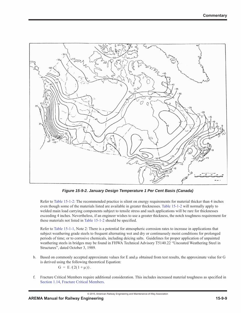
Commentary
© 2015, American Railway Engineering and Maintenance-of-Way Association
AREMA Manual for Railway Engineering 15-9-9
1
3
4Refer to Table 15-1-2: The recommended practice is silent on energy requirements for material thicker than 4 inches even though some of the materials listed are available in greater thicknesses. Table 15-1-2 will normally apply to welded main load carrying components subject to tensile stress and such applications will be rare for thicknesses exceeding 4 inches. Nevertheless, if an engineer wishes to use a greater thickness, the notch toughness requirement for these materials not listed in Table 15-1-2 should be specified.
Refer to Table 15-1-1, Note 2: There is a potential for atmospheric corrosion rates to increase in applications that subject weathering grade steels to frequent alternating wet and dry or continuously moist conditions for prolonged periods of time; or to corrosive chemicals, including deicing salts. Guidelines for proper application of unpainted weathering steels in bridges may be found in FHWA Technical Advisory T5140.22 “Uncoated Weathering Steel in Structures”, dated October 3, 1989.
b. Based on commonly accepted approximate values for E and obtained from test results, the approximate value for G is derived using the following theoretical Equation:
f. Fracture Critical Members require additional consideration. This includes increased material toughness as specified in Section 1.14, Fracture Critical Members.
Figure 15-9-2. January Design Temperature 1 Per Cent Basis (Canada)
G E 2 1 += .

Steel Structures
© 2015, American Railway Engineering and Maintenance-of-Way Association
15-9-10 AREMA Manual for Railway Engineering
9.1.2.2 WELDING (2003) R(2014)
a. Prior to 1990, these recommended practices stipulated that welding of structural steel should conform to the American Welding Society Structural Welding Code Steel ANSI/AWS D1.1. With the introduction of the Bridge Welding Code ANSI/AASHTO/AWS D1.5 in 1988, under a joint development effort of the American Association of State Highway and Transportation Officials (AASHTO) and the American Welding Society (AWS), the AREMA had available a welding specification that specifically addresses bridge construction. The development of the AWS D1.5 code represents a landmark of cooperative industry action to address the proliferation of costly and sometimes contradictory regulations. While some specifications of AWS D1.5 may appear unorthodox to members of the welding community, AWS has agreed that AASHTO should play a deciding role in determining the specifics of the code.
b. Since AWS D1.5 is directed toward the construction of highway bridges constructed in accordance with standard State Specifications, several terminology and definition substitutions must be made in order to render the bridge code applicable to the construction of railroad bridges.
c. ASTM A709, Grade HPS 70W steel was developed starting in 1994. By 1997 the material was ready for use in bridge structures. The “Guide Specification for Highway Bridge Fabrication with HPS 70W Steel” was developed by the industry and subsequently adopted by AASHTO. This guide recommends procedures that will result in economical, high-quality fabrication using A709 HPS 70W steel. The guide is intended to be used as a supplement to AWS D1.5.
9.1.2.5 DEFLECTION (2013) R(2014)
b. Prior to 1969, the deflection limitation was covered by an article headed “Depth Ratios.” Structures built with depth ratios meeting the requirements of that article were satisfactorily stiff for railroad operations since the stresses allowed for A36 (or A7) steel were used in the design. An explanation in 1959 stated that depth ratios resulted in deflections of 1/800 for girders and trusses and 1/600 for rolled beams used as girders under E72 loading (Reference 20). A statement to use 1/640 if shallower depth spans were required appeared in 1962 (Reference 22). Since the 1969 edition of these recommended practices introduced and permitted the use of a variety of higher strength steels, it became necessary to define more accurately the degree of stiffness which is desirable in terms of the deflection of the structure rather than in terms of the depth ratio (Reference 23). Relating deflection to live loading also gives a more appropriate basis for ballasted deck bridges, for which the live load is generally a lesser percentage of total load than for open deck bridges.
c. Waddell (1916) recommended a vibration load of 700 lb. per linear foot for loaded chords to ensure sufficient lateral rigidity in members (Reference 154). Furthermore, observations and tests at CN determined that lateral forces on bridges from equipment can exceed the forces given in Article 1.3.9. Nevertheless, experience indicates that the provisions for lateral forces of this Chapter have generally resulted in satisfactory structures with sufficient lateral rigidity when all the recommended loads and lateral forces are considered.
The lateral deflection limits recommended are 50% of the FRA allowable limits for alignment deviation for Class 5 Track (Reference 50). Therefore, at least 50% of the allowable limit remains for variations in track alignment, rail wear and track fastener wear or movement. For higher Classes of track the allowable limit needs to be reduced accordingly. The limit is applied over a 62 foot chord for tangent track and curved track and also on a 31 foot chord for curved track.
9.1.2.6 CLEARANCES (1995) R(2014)
The requirements for clearances were changed in the 1983 edition to be slightly more severe than in previous editions (previously changed in 1969). This was done to be consistent with the recommendations of AREMA Committee 28 to accommodate the increased dimensions of cars and of higher and wider loads.
Commentary
© 2015, American Railway Engineering and Maintenance-of-Way Association
AREMA Manual for Railway Engineering 15-9-11
1
3
4
9.1.2.14 SPECIAL TRACKWORK ON BRIDGES (2015)
The possibility of derailment is higher at locations where there is special trackwork.
Any gap in the rail or rail surface discontinuity also potentially increases the impact generated. Movable bridge joints are covered in Part 6. Expansion joints are covered in Part 8.
With regard to switches, the worst cases are those where an entire turnout is installed on a bridge that has a frog with a gap (Rail Bound Manganese (RBM) Solid Self Guarded Manganese (SSGM) or rigid frog). Similar effects occur when only the frog of a switch is located on a bridge. (Reference 128)
Where the switch (point of switch to heel of switch point) is installed on a bridge and the frog is off the bridge, the verticalimpact is less but the switch induces lateral impact to bridges. This may become a deck fastener issue on open decks and a ballast issue on ballast deck bridges.
While installing turnouts on bridges is not advisable, it is sometimes unavoidable. There are ways to reduce and possibly mitigate the effect (impact) by use of spring or moveable point frogs.
Placing a crossing diamond on a bridge is not recommended.
9.1.3 LOADS, FORCES AND STRESSES
9.1.3.3 LIVE LOAD (1995) R(2014)
a. The recommended live load of Cooper E 80 for the design of steel structures was adopted in 1967 by Committee 15. While locomotives with weights greater than Cooper E 72, the previously recommended design live load, are not likely to be found on any railroad in the United States, there is a trend toward heavier locomotives, and some of the heavy cars produce loads equivalent to Cooper E 80 or greater.
Heavy double stack cars with axle loads of 78,750 lb per axle and 4–axle 315,000 lb gross weight cars (both using the so-called 120 or 125 ton truck) accepted in regular service on certain railroads produce the equivalent of nearly E 80 Loading on shorter spans. In 1995, an alternate loading was introduced with a spacing similar to coupled typical 4–axle cars with an axle load 25% higher than the Cooper E 80 load to address problems associated with fatigue on shorter span lengths.
d. For members receiving load from more than one track, the proportions of full live load on the tracks to be used for design are determined by use of the theory of probability to determine the frequency with which stresses of various magnitudes might occur. Consideration was given to the fact that most of the trains which pass over a bridge will produce lower stresses than the recommended design live load on each track (Reference 140).
9.1.3.4 DISTRIBUTION OF LIVE LOAD (1993)1 R(2014)
9.1.3.4.2 Ballasted Deck Structures
The recommendation for distribution of load to ballasted deck structures is based on tests performed by the AAR and reported in AREA Proceedings, Vol. 56, 1955, page 45, other prior tests, and Report No. ER-5 of Engineering Research Division of AAR of February, 1961.
1 Reference 127
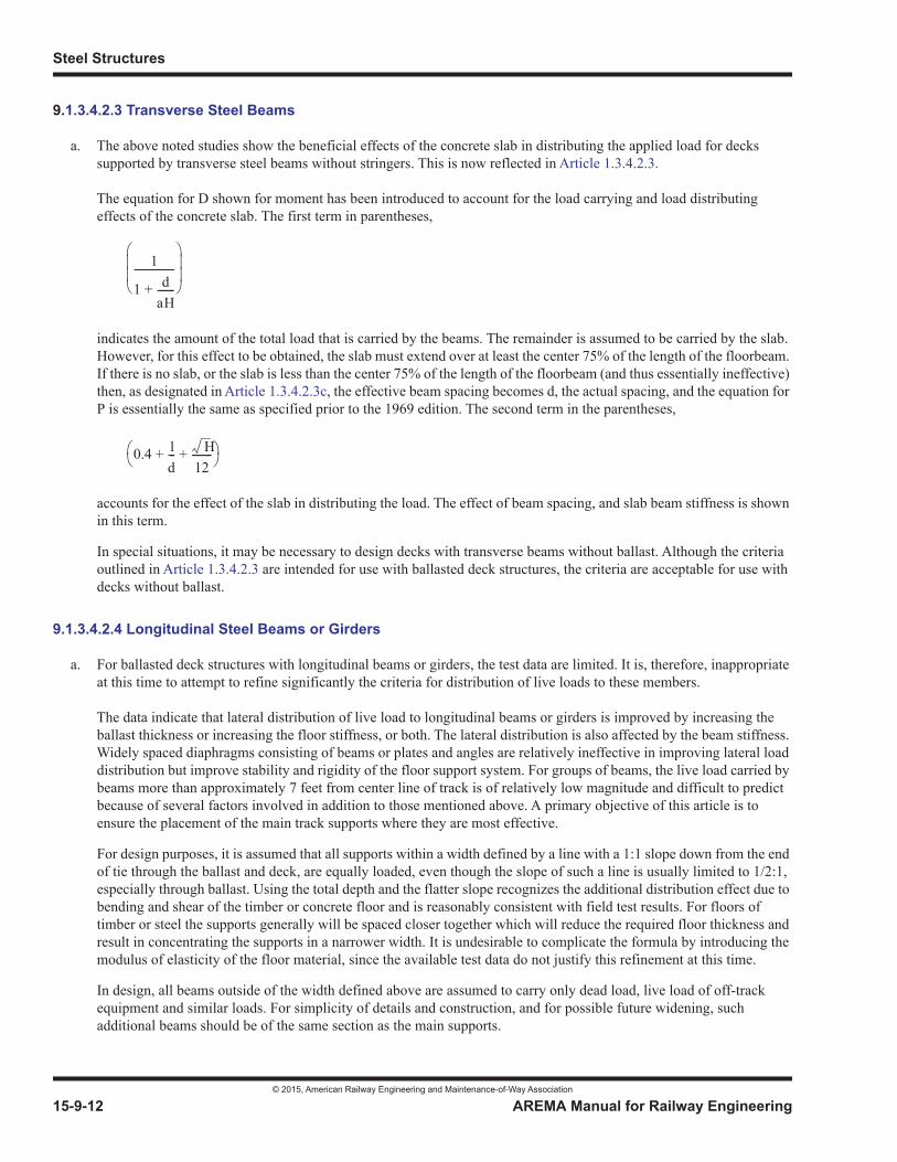
Steel Structures
© 2015, American Railway Engineering and Maintenance-of-Way Association
15-9-12 AREMA Manual for Railway Engineering
9.1.3.4.2.3 Transverse Steel Beams
a. The above noted studies show the beneficial effects of the concrete slab in distributing the applied load for decks supported by transverse steel beams without stringers. This is now reflected in Article 1.3.4.2.3.
The equation for D shown for moment has been introduced to account for the load carrying and load distributing effects of the concrete slab. The first term in parentheses,
indicates the amount of the total load that is carried by the beams. The remainder is assumed to be carried by the slab. However, for this effect to be obtained, the slab must extend over at least the center 75% of the length of the floorbeam. If there is no slab, or the slab is less than the center 75% of the length of the floorbeam (and thus essentially ineffective) then, as designated in Article 1.3.4.2.3c, the effective beam spacing becomes d, the actual spacing, and the equation for P is essentially the same as specified prior to the 1969 edition. The second term in the parentheses,
accounts for the effect of the slab in distributing the load. The effect of beam spacing, and slab beam stiffness is shown in this term.
In special situations, it may be necessary to design decks with transverse beams without ballast. Although the criteria outlined in Article 1.3.4.2.3 are intended for use with ballasted deck structures, the criteria are acceptable for use with decks without ballast.
9.1.3.4.2.4 Longitudinal Steel Beams or Girders
a. For ballasted deck structures with longitudinal beams or girders, the test data are limited. It is, therefore, inappropriate at this time to attempt to refine significantly the criteria for distribution of live loads to these members.
The data indicate that lateral distribution of live load to longitudinal beams or girders is improved by increasing the ballast thickness or increasing the floor stiffness, or both. The lateral distribution is also affected by the beam stiffness. Widely spaced diaphragms consisting of beams or plates and angles are relatively ineffective in improving lateral load distribution but improve stability and rigidity of the floor support system. For groups of beams, the live load carried by beams more than approximately 7 feet from center line of track is of relatively low magnitude and difficult to predict because of several factors involved in addition to those mentioned above. A primary objective of this article is to ensure the placement of the main track supports where they are most effective.
For design purposes, it is assumed that all supports within a width defined by a line with a 1:1 slope down from the end of tie through the ballast and deck, are equally loaded, even though the slope of such a line is usually limited to 1/2:1, especially through ballast. Using the total depth and the flatter slope recognizes the additional distribution effect due to bending and shear of the timber or concrete floor and is reasonably consistent with field test results. For floors of timber or steel the supports generally will be spaced closer together which will reduce the required floor thickness and result in concentrating the supports in a narrower width. It is undesirable to complicate the formula by introducing the modulus of elasticity of the floor material, since the available test data do not justify this refinement at this time.
In design, all beams outside of the width defined above are assumed to carry only dead load, live load of off-track equipment and similar loads. For simplicity of details and construction, and for possible future widening, such additional beams should be of the same section as the main supports.
1
1 daH-------+
----------------
0.4 ld--- H
12--------+ +
Commentary
© 2015, American Railway Engineering and Maintenance-of-Way Association
AREMA Manual for Railway Engineering 15-9-13
1
3
4
9.1.3.5 IMPACT LOAD (2007) R(2014)
a. The impact loads specified are based on investigations and tests of railroad bridges in service under passage of locomotives and train loads. The early tests, prior to 1935, were made with mechanical instruments and included measurements of deflections and strains. In general and particularly for shorter spans, the instruments were subject to considerable error due to vibration. Later tests (Reference 124) were made with electrical instruments which permitted more accurate measurements without disturbance from vibrations.
The impacts calculated by the formulas given in this article do not include the effect of impulsive loads that are not substantially attenuated between the rail and the structure. For example, direct fixation of the rail to a steel deck without some appropriately designed attentuation device is not covered. Such impacts have been measured to be as high as 600%. (References 47, 79)
b. Tests (Reference 21) have shown that the impact load on ballasted deck bridges can be reduced to 90% of that specified for open deck bridges because of the damping which results from the mass and resiliency of the ballast on a ballasted deck bridge.
d. The impact load due to rocking effect, RE, is due to a couple created by 20% of the wheel load acting down on one rail and up on the other rail, which effect was called roll prior to 1967. By service tests (Reference 27), it was established that the roll effect was essentially the same for all speeds. In 1967, the term 100/S (S in feet) was introduced as a downward load only (Reference 26), which approximates the effect of roll used in previous recommended practices. S was defined as the distance between centers of single or groups of longitudinal beams, girders or trusses; or the length between supports of floorbeams or transverse girders. Because of inconsistent interpretations of the term 100/S (S in feet) the term RE was introduced in 1991.
In accordance with Article 1.3.5a, impact load due to rocking effect, RE shall be determined as a percentage of live load applied vertically at each rail. RE is then added to the impact load due to vertical effects (Article 1.3.5c) to determine the total impact load expressed as a percentage of the specified live load.
The impact load due to rocking effect, RE, is created by a rocking load equal to the applied force couple of 20% of the wheel load acting vertically at each rail. Vertical loads in members due to the rocking load can be calculated for steel bridge span members based on the distribution of the rocking load to members supporting the track. RE can then be expressed as a percentage of specified live load by determining the ratio of the vertical load due to rocking to the vertical due to otherwise specified vertical live loads in each member supporting the track (for example, if the distribution of rocking load to members supporting the track is assumed to be the same as the distribution of vertical live load, RE expressed as a percentage of live load, will be equal for all members supporting the track).
For spans with one longitudinal beam, girder or truss per rail the impact load due to rocking effect, RE, is (100/S)% of the vertical live load applied at each rail, where S, feet, is the distance between the centers of the longitudinal beams, girders or trusses. The constant of 100 represents the effective rail spacing of 5 feet times the load factor of 20 percent.
For spans with more than one longitudinal beam, girder or truss per rail the impact load due to rocking effect, RE, (expressed as a percentage of live load) depends on the distribution of rocking load and specified vertical loads to the members supporting the track. Vertical loads shall be distributed to members supporting the track in accordance with Article 1.3.4. The distribution of rocking loads to members supporting the track shall be based on the configuration and spacing of members supporting the track.
For floorbeams and transverse girders the impact load due to rocking effect, RE, is (100/S)% of the vertical live load applied at each rail, where S, feet, is the distance between the supports of floorbeams or transverse girders.
e. The requirements specified for members receiving load from more than one track are based on judgement. For a double track span, the shortest span for which the impact load for only one track is to be used is 225 feet. For an open deck through span of this length the use of the impact load for the second track would add approximately 5% to the total design load of the truss. The probability that full impact load effects will occur simultaneously for both tracks is remote, but should this happen, the resulting increase in total load is small.
Steel Structures
© 2015, American Railway Engineering and Maintenance-of-Way Association
15-9-14 AREMA Manual for Railway Engineering
9.1.3.6 CENTRIFUGAL FORCE (2002) R(2014)
a. The centrifugal force defined in Section 1.3.6 is a function of curvature and speed (Reference 26). The centrifugal force contributes to the horizontal forces applied to the bridge through the outer rail of a curve, and affects the proportion of the vertical force taken by each rail.
b. In cases where the maximum train speed for the expected life of the bridge on a curve is not limited by other conditions, it is constrained by a practical maximum superelevation of 6 inches (150) and a maximum underbalance of 3 inches (75), which equates to equilibrium speed for a superelevation of 9 inches (225). At that point, regardless of the actual curvature and corresponding speed, the proportion of centrifugal to vertical force is very close to 0.15.Article 1.3.6(b) is based upon the assumptions that, at some time in the life of the bridge, a superelevation of 6 inches (150) could be applied to the track, and trains could be operated at the corresponding maximum speed, with superelevation underbalance of 3 inches (75).
c. In cases where the maximum train speed for the expected life of the bridge is limited by other factors, the design speed may be reduced to that specified by the Engineer in accordance with the provisions of Chapter 5 of this Manual, with the centrifugal force factor and superelevation adjusted accordingly.
d. On superelevated curves, the point of application of the vertical load will be offset horizontally toward the center of the curvature. Article 1.3.6(d) accounts for this offset.
e. Article 1.3.6(e) accounts for the application of the entire horizontal centrifugal force at the flange of the wheel on the outer rail, combined with the proportion of vertical load, with full impact, taken by the outer rail. No horizontal force is assumed at the inner rail, as any horizontal wheel forces applied at the inner rail are normally canceled by the other wheels at the same side of that truck.
9.1.3.7 WIND FORCES ON LOADED BRIDGE (2009) R(2014)
a. The recommended use of 300 lb per linear foot for wind force on a train on a bridge as contained in Article 1.3.7a is adequate for use on lines where double stack equipment is not operated. The engineer should consider increasing this force in areas where double stack equipment, or other equipment with a large vertical projection operates, and strong wind gusts are known to occur.
b. The specified basic wind pressure of 30 lb per square foot on a structure carrying live load has a long historic background in railroad recommended practices. It was assumed that the maximum wind velocity under which train operations would be attempted would produce a load of 30 lb per square foot on a flat surface normal to the wind. The provisions of Article 1.3.7b (1), (2), and (3) were selected to make provisions for the effect of the wind on the portions of the structure which are behind, and partly shielded by, the portion of the structure directly exposed to the wind pressure.
c. Article 1.3.7c promotes proper proportioning of affected members in order to attain rigidity for the structure as a whole. It does not actually address wind loads, but rather a “notional” load which was once termed “vibration load” in earlier bridge specifications (Reference 154). This load is included in the section on wind load because it is applied as an alternative to wind load. The affected members are to be proportioned for the greater force of either the wind load or this “notional” load.
9.1.3.8 WIND FORCES ON UNLOADED BRIDGE (2005) R(2014)
The specified basic wind force of 50 lb per square foot on an unloaded structure has a long historic background in railroad specifications. It was assumed that a hurricane wind, during which train operations would not be attempted, could produce a load of 50 lb per square foot on such surfaces.

Commentary
© 2015, American Railway Engineering and Maintenance-of-Way Association
AREMA Manual for Railway Engineering 15-9-15
1
3
4
9.1.3.10 STABILITY CHECK (2005) R(2014)
a. For wind, nosing, and centrifugal forces, the vertical weight of a train on a tower or pier usually improves the lateral stability of the structure, so it is prudent to model the least weight train that would be present with the applicable lateral overturning load. A uniform vertical loading of 1,200 lbs/ft applied to the leeward track represents a consist of empty cars.
For multiple track structures supported by the same pier(s) only the leeward track is loaded.
b. This stability check is designed to ensure that a load equal to half the full design load on the verge of incipient roll willnot cause the span to roll over. It is not intended to prevent damage to the structure, nor is it intended for deck design.
9.1.3.12 LONGITUDINAL FORCES (2005) R(2014)
The longitudinal force used in previous editions of this Manual of recommended practice has changed over time. In the 1905 edition, the force was 20 percent of the specified total live load. By the 1920 edition reductions were permitted for ballast deck spans and for short structures. In the 1932 edition, the additional force of 25 percent of the driving axles of the Cooper’s series was introduced, and the braking force of 15 percent of the Cooper’s train was introduced.
The AAR conducted a number of tests with the secondary objective of measuring longitudinal forces in the 1940’s and 1950’s. None of these tests were conducted under conditions that would have approached the maximum possible longitudinal force available at that time.
It became the practice of some railroads to use one half the specified force which by this time was 25 percent of the Cooper’s driving axles or 15 percent of the Cooper’s train on the appropriate loaded length.
In the 1968 edition of the Manual, a factor L/1200 was introduced to be applied to the 15 percent of the Cooper’s train with anexception for bridges with discontinuous rail (e.g.: movable bridges and those with sliding joints or switches). This resulted in a vastly reduced longitudinal force requirement. The traction force of 25 percent of the weight on driving axles was eliminated.
A similar change was made to Chapter 8, Concrete Structures and Foundations. Committee 7, Timber Structures, did not make changes to the recommended practice in Chapter 7.
With the introduction of high-adhesion locomotives, load/empty brakes, and ECP brakes, concern was expressed that recommended forces were not high enough. Several railroads have acknowledged component failures in bridges due to longitudinal forces, and several structures have been replaced due to distress caused by high longitudinal forces.
In 1996, the AAR conducted a test specifically to investigate longitudinal forces under the newly developed AC diesel-electric freight locomotives. The test demonstrated that a longitudinal force of about 100 kips (440 kN) on a 50-foot (15-meter) open-deck span was more than 25 times the design force in the 1996 edition of the Manual.
Under direction from the Board of Directors, and with the concurrence of the chairmen of the structural committees (7, 8 and 15) who formed the nucleus of a quickly gathered ad-hoc committee, AREA revised its recommended practice for the 1997 edition to conform to this test result. Chapter 7 was thought to be appropriate and not warrant the emergency change.
The AAR followed this test with further tests, all of which confirmed the much higher longitudinal forces, and the far greater percentage of those forces which went into the structure. On a four-span, 400-foot (122-meter) open-deck steel bridge, longitudinal forces up to 330 kips (1470 kN) were measured in the entire structure, with up to 220 kips (980 kN) in a 210-foot (64-meter) truss, and up to 110 kips (490 kN) in a 42-foot (13-meter) beam span. On a two-span, 121-foot (37-meter) open-deck steel DPG bridge, forces up to 140 kips (620 kN) were measured in the entire structure, with up to 96 kips (430 kN) in a 55.5-foot (17-meter) span. On a single-span, 60-foot (18-meter) ballast-deck steel DPG bridge, forces up to 115 kips (510 kN) were measured. All tests used sets of two or three AC locomotives, operated near their maximum tractive effort capabilities of

Steel Structures
© 2015, American Railway Engineering and Maintenance-of-Way Association
15-9-16 AREMA Manual for Railway Engineering
180 kips (800 kN) to 200 kips (890 kN) per locomotive. Further information about these tests can be found in Reference 63,81, 91, 92, 102, 103, 104, 105, 106, 107, 108, 109, 110, 112, 114, 138, 139, 141, 148, 149 and 150.
The results of these tests indicated the following:
(1) Ballast deck spans do not have lower longitudinal forces
(2) Short spans do not have significantly lower longitudinal forces
(3) Half the force is not always dissipated through the rails
(4) There has been considerable confusion over the difference between the force and its distribution and path
(5) High longitudinal forces are not necessarily grade related
(6) High longitudinal forces are related to lower speeds for tractive effort and dynamic braking situations. When a train is maintaining a speed that exceeds 15 mph (25 km/h) it cannot exert the maximum tractive effort. To cover future developments, the recommended practice has used 25 mph (40 km/h).
(7) High longitudinal forces due to braking can occur at any location, particularly if an emergency brake application occurs
(8) The ability of the approach embankments to resist longitudinal forces from the superstructure is reduced as longitudinal forces are also applied to the approach embankments. This would be the case with several locomotives passing over a short bridge, or a train braking.
Analytical confirmation of the above behaviors has been done by Foutch et al (Reference 62, 63, 108, 141 and 147), and is also explained by Fryba (Reference 64). Unfortunately, these formulations are too cumbersome for routine work. The problem can be envisioned as the rails being continuously supported in the longitudinal direction. The longitudinal stiffness of the connection between the rails and the bridge is similar to the stiffness of the connection between the rails and fixed ground onthe approach embankments.
With regard to braking force, the maximum adhesion between wheel and rail is about 15 percent. This level of braking would typically be reached with an emergency application of the train air brakes. The equation for train braking is derived using 15percent of the Cooper live loading.
Longitudinal force due to braking acts at the center of gravity of the live load. Center of gravity height is taken as 8 feet (2500mm) above the top of rail. This force is transferred from vehicle to rail as a horizontal force at the top of rail and a verticalforce couple transmitted through the wheels.
Longitudinal force due to locomotive traction acts at the drawbar. Drawbar height is taken as 3 feet (900 mm) above top of rail. As with braking, this force is transferred from vehicle to rail as a horizontal force at the top of rail and a vertical forcecouple transmitted through the wheels.
Longitudinal forces transmitted by tractive effort of locomotives or the braking action of trains will be distributed to bridgemembers in accordance with their relative stiffness and orientation with respect to the force path between the applied longitudinal force and the supporting substructure.
The length “L” in Article 1.3.12 is to be taken as the appropriate length for the structure or portion of the structure under consideration. The length selected should be the one that produces the maximum force in the structure or portion of the structure under consideraton.
Commentary
© 2015, American Railway Engineering and Maintenance-of-Way Association
AREMA Manual for Railway Engineering 15-9-17
1
3
4
In bridges with stringer and floorbeam floor systems, longitudinal forces are first applied to the stringers. The force must thenbe transferred to the members to which stringers are connected, usually the floorbeams. Traction bracing can be used to directly transfer the longitudinal force from the stringers to truss or girder panel points.
In bridges with transverse floorbeam floor systems (such as through girder spans), traction bracing can be used to transfer thelongitudinal force to the bridge members supporting the floorbeams (typically girders).
It is generally considered good practice to design traction bracing to be the same depth as the member being braced. However, when traction bracing isn’t used, the floorbeams should be designed for transverse bending and torsion where applicable. See Reference 68. It is generally considered good practice to provide traction bracing rather than design floorbeams or transverse members for lateral bending and torsion.
Fixed bearings and their anchorages should be designed to transfer the longitudinal force from superstructure to substructure. In addition to designing the fixed bearings to take all the longitudinal forces, it is the practice of some engineers, given thatbearings tend to become frozen or stuck with time, to design the area around and below expansion bearings for a percentage of the longitudinal forces going through those bearings as though the expansion bearings were partially fixed.
Longitudinal forces are of importance in railway trestle bridges and may govern the economic span length considering requirements for longitudinal bracing and column sizes in towers.
9.1.3.13 FATIGUE (2013) R(2014)
The following symbols are used within Article 9.1.3.13:
N = Number of occurrences of constant stress cycles which would cause fatigue damage equivalent to the fatigue damage caused by a larger number, Nv, of variable stress cycles
ni = Number of stress cycles for each of the stress range values represented in the distribution being considered
Nv or n = Total number of variable stress cycles in the distribution or life
SR = Stress range, the algebraic difference between the maximum stress and the minimum stress for a stress cycle
SRact = Stress range actually created at a given location in the structure by a moving load
SRfat = Allowable fatigue stress range as listed in Table 15-1-10
SRi = Stress range of cyclic stress corresponding to the number of occurrences, ni
SRe = Effective cyclic stress range for the total number of variable stress cycles, Nv.
SRRMC =(Root Mean Cube Stress
Range) = SRact/SR or Eact/Eapplied ratio when SR is calculated by using the same load which was applied
when SRact was measured. Field measurements have shown the measured SR is equal to a factor, times the calculated SR. This reduction reflects the beneficial effects of participation by the
bracing, floor system, or other three-dimensional response of the structure and, also, the fact that full impact does not occur for every stress cycle. Since SR at a given location is directly proportional to the loading used, Eact/Eapplied also equals this ratio.
i = The ratio of the number of occurrences of SRi to the total number of variable stress cycles, Nv
SRmin = stress range or lower limit value for the starting point of the function being considered
niSRi3
ni------------------------
3
Steel Structures
© 2015, American Railway Engineering and Maintenance-of-Way Association
15-9-18 AREMA Manual for Railway Engineering
a. Fatigue is now covered in a sufficient number of texts so a basic explanation is no longer needed in this Commentary. It was removed in 2009.
Between 1910 and 1969, inclusive, this Manual required an increase of each stress by 50% of the smaller stress for members subject to reversal of stress.
Fatigue damage prior to the introduction of 263,000 lb. cars (100 ton capacity) in the 1960’s was primarily the result of the passage of heavier locomotives. With 20 trains a day for 60 years, the number of damaging cycles caused by locomotives would be less than 500,000. Most freight cars were light enough to cause little if any damage due to fatigue.
In 1969, methods were introduced based on the R ratio, the ratio of minimum to maximum stress, and a distinction was made between cases of more than 500,000 cycles of load or less (Reference 97). Consideration of the methods used to fabricate and connect members was included.
Fatigue problems accelerated in the 1970s, with the introduction of heavy and frequent unit train service where the influence of each car produces a significant effect. With the same 20 trains a day with 60 cars per train causing damage, 500,000 cycles could accumulate in one year for some members.
Fatigue design for this Chapter has been based entirely on the nominal stress range concept since the 1978 Edition.Other factors, such as mean stress and steel strength have negligible effect in the types of fabricated structures used in the railroad industry. The type of load distribution has been revised as new knowledge has been developed.
Structures designed to the fatigue criteria of Article 1.3.13 should be adequate for:
(1) continuous unit trains with axle loads not exceeding 80,000 lb for loaded lengths less than 100 feet,
(2) continuous unit trains with equivalent uniform load not exceeding 6,000 lb per foot of track and axle loads not exceeding 80,000 lb, or other variations of higher load with fewer cycles on longer spans (see Article 9.1.3.13.c).This should be adequate for mainlines of Class I railroads, and for most heavy haul lines.
The Chapter recommends special consideration for spans exceeding 300 feet (see Article 9.1.3.13j).
b. The major factors governing fatigue strength are the number of stress cycles (covered in section c), the magnitude of the stress range (section h), and the type of constructional detail (section g).
c. The derivation of the design criteria for fatigue did not consider Rail Transit or other Light Rail facilities. For such cases, unless demonstrated otherwise, the number of constant stress cycles, N, should be > 2,000,000.
For typical North American freight railroads the number of cycles used for design were derived assuming 315,000 lb. cars in 110 car trains at a frequency of 60 trains per day over an 80-year period. The number of cycles per train is the result of extensive work done by G. Oommen, S. Beisler and R.A.P. Sweeney as reported to Committee 15 in 1987 and 1988 (See Table 15-9-1). This criterion will theoretically provide infinite life for all loaded lengths less than 100 feet and will accommodate longer and more frequent trains.
Existing cars (1988) with gross weights of 315,000 lb and certain double stack cars are approaching E 80 loading values on short spans. In order to provide sufficient fatigue capacity under solid, or “unit” trains of these types of vehicles the number of design cycles shown in Table 15-1-7 was derived by prorating the fatigue curve formula,
N = Nv x ( x SE60/SE80)3
to an equivalent number of cycles of E 80 loading. In this formula N is the number of cycles, is a constant, and SE60and SE80 are respectively the stress ranges characteristic of E 60 and E 80 loading. The total projected number of
SRN = Stress range which corresponds to N constant stress cycles for a given detail
Commentary
© 2015, American Railway Engineering and Maintenance-of-Way Association
AREMA Manual for Railway Engineering 15-9-19
1
3
4
variable stress cycles, Nv, shown in Column 5 of Table 15-9-1, is obtained by multiplying columns 2, 3 and 4. The value of alpha is to be taken as one unless a test on the member being evaluated indicates that a lower value is appropriate.
Table 15-9-1 is based on 110-vehicle train. Critical characteristic load is assumed to be ¾, i.e. 60/80, of design load E 80.
On spans exceeding 100 feet it may be necessary to increase the number of cycles per train if a consistent operating pattern of loaded cars followed by empty cars is repeated throughout the design train, throughout the service life of the bridge. It is theoretically possible to get 55 cycles on spans close to 100 feet if the pattern is 2 loaded cars followed by 2 empty cars. Nevertheless, the committee assumed 3 cycles of loaded-empty combinations in its design 110-car train as a more likely maximum on spans exceeding 100 feet.
It must be recognized that the number of variable cycles leading to the greater-than-2-million category in Table 15-1-10 is different for each category of detail, varying from 3 to 31 cycles per 110-car train on spans exceeding 100 feet.
d. Impact values used in design are estimated to have a probability of occurrence of 1% or less. Considering that a railroad bridge is normally designed for an 80-year period, this level of impact is quite likely to occur at least once during the bridge life and probably more frequently. For fatigue design the mean value of impact is more appropriate.
Nevertheless, the note to Table 15-1-8 covers cases of consistent and continuous poor maintenance practice with regard to wheel or track maintenance or places where there are joints in the rail due to switches or rail expansion or other joints where higher impact is a frequent occurrence. This is likely to include but is not restricted to locations where there is "FRA Excepted Track" or "FRA Class 1 Track."
In locations where a structural member supports or is influenced by a “Conley” or similar style joint or where there are rail break castings, a rail end connection or similar style joint or switch, the reduction in impact shown in Table 15-1-8 should not be used.
For members supporting end ties on movable spans and at the adjacent ends of fixed spans, use the full impact outlined in Article 6.3.3, unless test results show a lower permissible impact.
Observations on 37 spans with span lengths between 30 and 140 feet, summarized by W. G. Byers (Reference 36),indicates that mean impact values fall below 65% of the values used for design. Tests included results obtained with poor wheels and on poor track.
Tests on 15 bridges on Canadian National Railways done between 1975 and 1988 (reported to Committee 15, May 1988, by R. A. P. Sweeney) indicated mean values of 34% on spans less than 80 feet, and 65% on longer spans. A further presentation by Dr. Sweeney made to the committee in 2002 based on tests on over 100 bridges confirmed the
Table 15-9-1. Parameters Used to Develop Table 15-1-7 and Table 15-1-10
Classification I
1 2 3 4 5 6 7 8
Span LengthLFt
Lifein Days
80 Yr
No. of DailyTrains
StressCycles per
Train Crossing
Projected NvMillion
Alpha( )
NCol. 5
(Alpha x 6/8)3
Million
Nused in
Table 15-1-7Million
L > 100 29,200 60 3 5.3 1.0 2.2 2100 L > 75 29,200 60 6 10.5 1.0 4.4 >275 L > 50 29,200 60 55 96 1.0 41 >250 L 29,200 60 110 193 1.0 82 >2
Steel Structures
© 2015, American Railway Engineering and Maintenance-of-Way Association
15-9-20 AREMA Manual for Railway Engineering
numbers in revised Table 15-1-8, and confirmed that alpha should be assumed to be 1 unless a particular structure was tested and alpha proved to be lower for that structure.
The mean impact is a function of the geometry of the track and how well it is maintained up to and across the bridge, along with the maintenance standards for out-of-roundness of wheels and for wheel flats. The more restrictive limitations placed on short members without load sharing is based on the probability that a single wheel may cause such values relatively frequently. This is based on a one-year sample of wheel impact data at 10 Wheel Impact Load Detector (WILD) Sites on CN (Reference 40).
For Light Rail, the Mean Impact Load shown in Article 1.3.13d should be 100% of the impact load specified in Article 1.3.5 for all member span lengths, and in Table 15-1-7.
e. The fatigue criteria is based on continuous unit trains with equivalent uniform load not exceeding 6,000 lb per foot of track and axle loads not exceeding 80,000 lb and has been adjusted so that the Standard Cooper load specified in Article 1.3.3 may be used for design purposes.
f. For the usual design condition of members subjected to bending, only SR derived from bending needs to be considered for details, such as transverse stiffeners, which are subjected to shear stresses as well. The design detail categories have taken shear into account; therefore, principal stresses need not be considered in the usual design condition. For unusual design conditions, the principal stresses may need to be considered.
Residual and/or locked-in stresses induced during welding, fabrication or erection shall not be explicitly considered in investigating fatigue. Residual stresses due to welding are implicitly included through the specification of stress range as the sole dominant stress parameter for fatigue design. This same concept of considering only stress range has been applied to rolled, bolted, and riveted components or details where far different residual stress fields exist. The application to nonwelded components or details is conservative.
It has been shown that the level of total applied stress is insignificant to fatigue design for a welded steel component or detail in structures typically designed using this Manual.
A complete stress range cycle may include both a tensile and compressive component. Only the live load plus impact stresses need be considered when computing a stress range cycle; dead load does not contribute to the stress range. Tensile stresses propagate fatigue cracks. Material subjected to a cyclical loading at or near an initial flaw will be subject to a fully effective stress cycle in tension, even in cases of stress reversal, because the superposition of the tensile residual stress elevates the entire cycle into the tensile stress region.
These provisions shall be applied only to components or details subjected to a net applied tensile stress. In regions where the permanent loads produce compression, fatigue shall be considered and these provisions applied only if the tension component of the live load plus impact stress range cycle due to fatigue exceeds the permanent-load compressive stress in the component or at the detail under consideration.
Fatigue design criteria need only be considered for components or details subject to effective stress cycles in tension and/or stress reversal. If a component or detail is subject to stress reversal, fatigue is to be considered no matter how small the tension component of the stress cycle is since a flaw in the tensile residual stress zone could still be propagated by the small tensile component of stress. Hence, the entire stress range cycle (which may include compression) is used in computing the stress range. In addition, for fatigue to be considered, the component or detail must be subject to a net applied tensile stress under an appropriate combination of the permanent loads and the fatigue live load. The tensile component of the stress range cycle resulting from live load and its appropriate impact combination acting in conjunction with the compressive stress due to the permanent loads are used to establish the presence of a net applied tensile stress in the component or at the detail under consideration.
Cross-frames and diaphragms connecting adjacent girders are stressed when one girder deflects with respect to the adjacent girder. The sense of stress is reversed depending on which way roll is applied and this usually creates the largest stress range in these members. To cause one cycle of the stress range so computed requires two vehicles to roll in opposite direction. This has been observed in practice. For cases where the force effects in these members are
Commentary
© 2015, American Railway Engineering and Maintenance-of-Way Association
AREMA Manual for Railway Engineering 15-9-21
1
3
4
available from an analysis, such as in horizontally curved or sharply skewed bridges, it may be desirable in some instances to check fatigue-sensitive details on a bracing member subjected to a net applied tensile stress. In no case should the calculated range of stress be less than the stress range caused by full live load and appropriate impact load.
g. Components and details susceptible to load-induced fatigue cracking have been grouped into nine categories, called detail categories, of similar fatigue resistance established through full scale testing (Reference 9, 52, 85, 129, 161 and 164).
Table 15-1-9 illustrates many common details found in bridge construction and identifies potential crack initiation points for each detail. In Table 15-1-9, “Longitudinal” signifies that the direction of applied stress is parallel to the longitudinal axis of the detail. “Transverse” signifies that the direction of applied stress is perpendicular to the longitudinal axis of the detail.
Where fasteners and connected material are proportioned in accordance with Article 1.3.13 and Section 1.4, Basic Allowable Stresses, the fasteners will have greater fatigue life than the connected material (Reference 86). Thus, no categories for bolts or rivets in shear or bearing are required to replace the 1969 formulas.
For information on Partial Penetration (PJP) joints see Article 1.7.4 and its commentary.
Research on end-bolted cover plates is discussed in Reference 156.
h. The requirement that the maximum stress range experienced by a detail be less than the constant-amplitude fatigue threshold provides a theoretically infinite fatigue life for all loaded lengths less than 100 feet.
For longer spans see Article 9.1.3.13c.
For cases where different criteria are appropriate, the fatigue resistance above the constant amplitude fatigue threshold, in terms of cycles, is inversely proportional to the cube of the stress range, e.g., if the stress range is reduced by a factorof 2, the fatigue life increases by a factor of 23. This is reflected in the equation shown below and shown in Figure 15-9-3.
(Sr) = (A/N)1/3
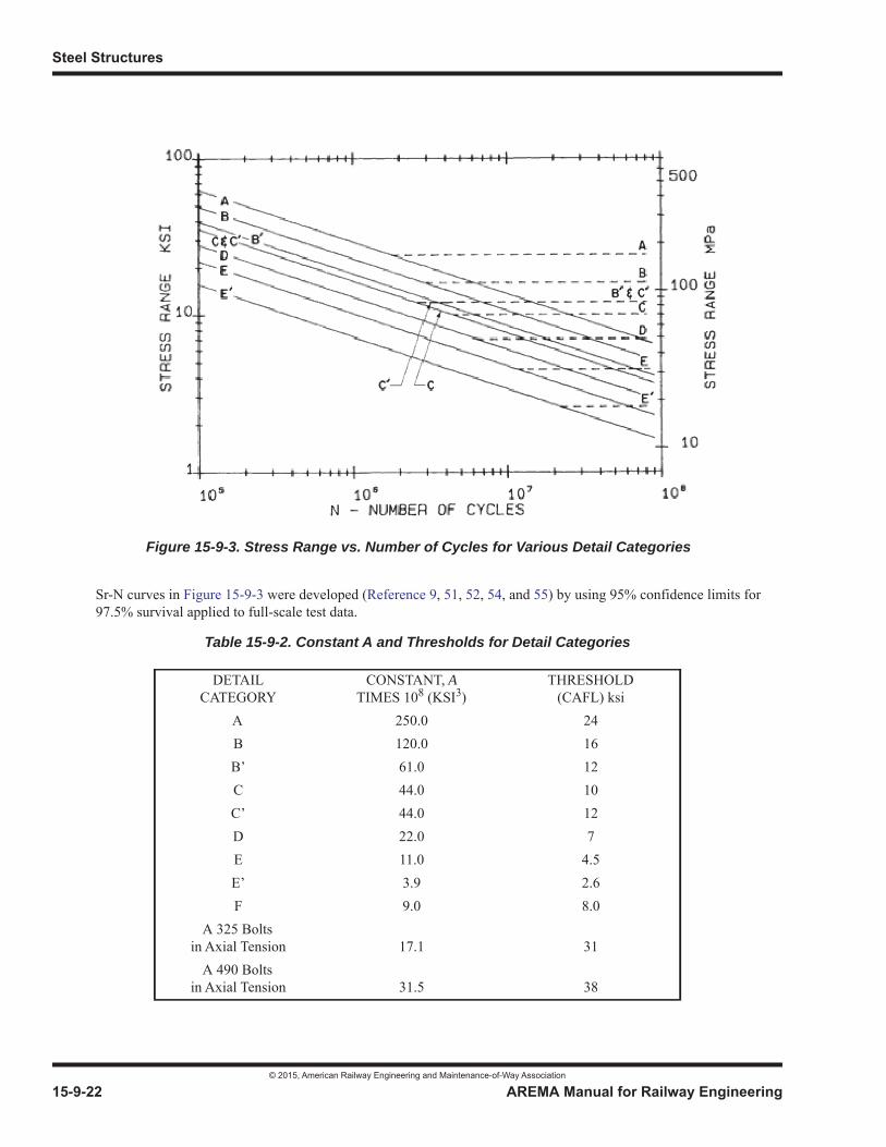
Steel Structures
© 2015, American Railway Engineering and Maintenance-of-Way Association
15-9-22 AREMA Manual for Railway Engineering
Sr-N curves in Figure 15-9-3 were developed (Reference 9, 51, 52, 54, and 55) by using 95% confidence limits for 97.5% survival applied to full-scale test data.
Table 15-9-2. Constant A and Thresholds for Detail Categories
DETAILCATEGORY
CONSTANT, ATIMES 108 (KSI3)
THRESHOLD(CAFL) ksi
A 250.0 24B 120.0 16B’ 61.0 12C 44.0 10C’ 44.0 12D 22.0 7E 11.0 4.5E’ 3.9 2.6F 9.0 8.0
A 325 Bolts in Axial Tension 17.1 31
A 490 Boltsin Axial Tension 31.5 38
Figure 15-9-3. Stress Range vs. Number of Cycles for Various Detail Categories
Commentary
© 2015, American Railway Engineering and Maintenance-of-Way Association
AREMA Manual for Railway Engineering 15-9-23
1
3
4
Detail Category F is for the allowable shear stress range on the throat of a fillet weld. When fillet welds are properly sized for strength considerations, Detail Category F should not govern. Fatigue will be governed by cracking in the base metal at the weld toe and not by shear on the throat of the weld.
i. Detail Category E and E’ details shall not be used on fracture critical members, and Detail Category D details shall be discouraged and used only with caution. Such details are highly susceptible to fatigue damage.
Eye bars and pin plates are design details which are not recommended except for very long truss spans where live load stress ranges are very low. In the event of their use, see Article 7.3.3.2 and the appropriate Commentary Article 9.7.3.3.2.
j. For span lengths exceeding 300 feet an analysis is required for each bridge component using influence lines and the preceding car types and load frequencies, accounting for the effect of lightly loaded vehicles interspaced within the design train.
k. When proper detailing practices are not followed, fatigue cracking has been found to occur due to strains not normally computed in the design process. This type of fatigue cracking is called distortion-induced fatigue. Distortion-induced fatigue often occurs in the web near a flange at a welded connection plate for a cross-frame where a rigid load path has not been provided to adequately transmit the force in the transverse member from the web to the flange. These rigid load paths are required to preclude the development of significant secondary stresses that could induce fatigue crack growth in either the longitudinal or the transverse member (Reference 56). It is emphasized that the stiffness of this connection is critical to prevent relative displacement between the components.
9.1.3.13.1 High-Strength Bolts Subjected to Tensile Fatigue Loading
Previous versions of this article were based on the 1969 edition of the Manual and distinguished between connections subject to less than or more than 500,000 cycles and were based on maximum applied stress.
The current limits are based on applied stress range with a maximum set at the constant amplitude fatigue limit for these bolts.Prying force was taken as 20% pending further testing.
The formula for the tensile stress area or effective bolt area is: 0.75 * cross-sectional area based on nominal bolt diameter (Reference 144).
9.1.3.13.2 Anchor Bolts Subjected to Tensile Fatigue Loading
This article is intended for anchor bolts subjected to repeated tension cycles. Examples of anchor bolts with tensile fatigue include hammerhead piers, outrigger bents, or continuous spans. Tension fatigue failures have been noted for anchor bolts on hammerhead piers using concrete columns with steel caps. The same situation can control in piers using concrete columns and steel pier caps such as in outrigger bents. This article is to ensure the assumed distribution of load to all anchor bolts on a pier cap or abutment that are fastening base plates for bearings intended to resist fluctuating tensile loads. It is not intended for the general situation of anchor bolts on a pier cap or abutment that are fastening base plates for bearings.
Experience with anchor bolt connections on hammerhead piers demonstrated that fatigue failures occur as a result of inadequate and highly variable bolt pretension within a group of bolts. Cracked bolts had modest levels of bolt tension whereasmost of the other bolts in the group had little or no pretension, with the partially pretensioned bolt resisting more than the intended share of live load. This resulted in fatigue crack development and fracture. To accomplish the appropriate pretension,where leveling nuts are used to position a steel pier cap on the column, steel shims may be inserted and the leveling nuts backed off before the grout pad is installed and anchor bolts are tensioned. Alternatively, the leveling nut anchor bolts can beignored in the design for resisting the applied loads.
If stainless steel is used for anchor bolts, AISI Stainless Steel 316 is the best choice for salt water exposure. This materialshould be available in bar stock to fabricate anchor bolts. It is identified in the ASTM A193 Standard Specification for Alloy-
Steel Structures
© 2015, American Railway Engineering and Maintenance-of-Way Association
15-9-24 AREMA Manual for Railway Engineering
Steel and Stainless Steel Bolting Materials for High Temperature or High Pressure Service and Other Special Service Applications. Other stainless steels in the A193 Specifications are not recommended.
9.1.3.14 COMBINED STRESSES (2005) R(2014)
9.1.3.14.1 Axial Compression and Bending
The straight line interaction formula is acceptable for small values of , but for values of greater than
0.15, the deflection of the column and the resulting increase in bending stresses caused by the axial load being made eccentric
must be taken into account. The formula accomplishes this by applying a magnification factor to
. This factor is similar in form to the formula (Reference 39) in which is the elastic (Euler) buckling stress of
the column loaded axially, divided by the applicable factor of safety, or in these recommended practices (see
Article 1.4.1).
When a member is braced in the plane of bending, at a panel point for example, there is no column deflection and, therefore, the magnification factor does not apply. Furthermore, the allowable axial stress here may be based on . The applicable formula then becomes . It should be noted that this formula does not apply at a connection point which is coincident with the location of maximum curvature of the deflected column axis, because such a point is not, in effect, braced.
The above remarks cover bending about one axis only. For bending about both axes, the three-term formulas obtained by expansion are sufficiently accurate for use.
9.1.3.15 SECONDARY STRESSES (1994) R(2014)
This article provides that secondary stresses due to truss distortion usually need not be considered in any member of the widthof which, measured parallel to the plane of distortion, is less than 1/10 of its length. An exception to this general provisionshould be the effects of secondary truss members, such as floorbeam hangers and subverticals; these may produce excessive secondary stresses in the chord unless adjustment is made in lengths of the verticals.
9.1.3.16 PROPORTIONING OF TRUSS WEB MEMBERS (2004) R(2014)
In determining whether it is safe to keep an old structure in service, the rules of Part 7, Existing Bridges, Section 7.3 Rating,govern. Experience with older structures designed for lighter live loads, shows that in such structures the web members of trusses reach their capacity sooner than other portions. This situation can be remedied either by providing an initial design ofall members for an increased live load at higher stresses or by providing a truss design under which the web members reach their safe live load capacity at substantially the same increased live load as the remainder of the truss. The latter method ismore economical and is provided by the recommended practices requirements (Reference 72).
f a
Fa-----
f b
Fb----- 1.0+
f a
Fa-----
f a
Fa-----
1
1f a
0.514 2E----------------------- kl
r-----
2–
-----------------------------------------------------
f b
Fb----- 1
1f aF e-------–
---------------- F e
0.514 2E
klr-----
2-----------------------
kl r 0=f a 0.55Fy f b Fb 1.0+
Commentary
© 2015, American Railway Engineering and Maintenance-of-Way Association
AREMA Manual for Railway Engineering 15-9-25
1
3
4
9.1.4 BASIC ALLOWABLE STRESSES
9.1.4.1 STRUCTURAL STEEL, RIVETS, BOLTS AND PINS (2011) R(2014)
In determining the allowable stresses, the value of 1.82, which is equal to 1/0.55, has been adopted as the usual factor of safetyin tension, based on the minimum yield point of the material. The same value has been used for such compression applications as are not affected by axial combined with bending effects.
Yielding of the gross area and fracture of the effective net area are considered the failure limit states. Yielding of the grossarea can lead to excessive elongation of the member. This uncontrolled elongation can precipitate failure of the overall structural system. Fracture of the effective net area was proposed by Munse and Chesson (Reference 38, and 96) and has been long since adopted as a limit state by both the AISC (References 12, 13, and 14) and AASHTO (Reference 7). The allowable stress of 0.47 Fu has been adopted by AREMA to align with AASHTO and to provide an additional factor of safety due to the sudden nature of this failure state.
The more conservative design approach for pin connected members is based on the results of experimental research (Reference 80).
Since there have been more failures in floorbeam hangers with riveted connections than in other members, a greater apparent factor of safety has been adopted for such members (Reference 30).
From 1935 to 1969, the secant formula, and parabolic type formula approximating it, formed the basis for the column formula of these recommended practices. It has been somewhat difficult to use and an assumed value of ec/r2 such that reasonable values result for intermediate column lengths makes the allowable stress on short columns less than necessary. For these reasons, and because long columns and eccentrically loaded columns can be provided for by Euler type formulas and interaction formulas, respectively, without resort to the secant formula, the use of the secant formula was discontinued.
The column curve of the Column Research Council (now titled Structural Stability Research Council) (Reference 41) which can be expressed in the symbols adopted in these recommended practices:
was selected as the basic curve for the development of the formulas used in these recommended practices. Studies were made which included plots of this curve with variable factors of safety such as that used by AISC (Reference 8), and with constant factors of safety 1.8, 1.9 and 2.0. Many varieties of column curves were plotted on the chart on which these Column Research Council curves had been plotted, and it was decided that the most practical form to be used was one involving the three formulas of the recommended practice.
The difficulty of evaluating k in railroad bridge compression members may lead to allowable stresses that are too high, especially in the approximate range of kl/r between 40 and 100, where a slight variation in k will have a large effect on the allowable stress. Some protection against this danger is provided by the adopted straight line formula as compared to the Column Research Council curve.
The formula to be used in determining the allowable compressive stress in the extreme fibers of welded built-up or rolled beam flexural members symmetrical about the principal axis in the plane of the web (other than box-type members) is based on theoretical studies made by Professors George Winter and Bruno Thürliman. In Professor Winter’s discussion of a paper by Karl de Vries, he developed formula (Reference 162) for fc, the critical stress for failure of the beam. This formula may be written:
f FyFy
2
4 2E------------- kl
r-----
2–=
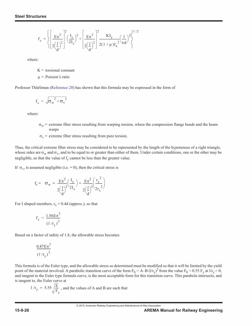
Steel Structures
© 2015, American Railway Engineering and Maintenance-of-Way Association
15-9-26 AREMA Manual for Railway Engineering
where:
Professor Thürliman (Reference 28) has shown that this formula may be expressed in the form of
where:
Thus, the critical extreme fiber stress may be considered to be represented by the length of the hypotenuse of a right triangle,whose sides are w and v, and to be equal to or greater than either of them. Under certain conditions, one or the other may be negligible, so that the value of fc cannot be less than the greater value.
If v, is assumed negligible (i.e. = 0), then the critical stress is
fc =
For I shaped members, rx = 0.4d (approx.), so that
Based on a factor of safety of 1.8, the allowable stress becomes
This formula is of the Euler type, and the allowable stress so determined must be modified so that it will be limited by the yieldpoint of the material involved. A parabolic transition curve of the form Fb = A–B (l/ry)2 from the value Fb = 0.55 Fy at l/ry = 0, and tangent to the Euler type formula curve, is the most acceptable form for this transition curve. This parabola intersects, andis tangent to, the Euler curve at
, and the values of A and B are such that
K = torsional constant = Poisson’s ratio
w = extreme fiber stress resulting from warping torsion, where the compression flange bends and the beam warps
v = extreme fiber stress resulting from pure torsion.
f cE 2
2 ld---
2---------------
2Iy
2Ix-------
2 E 2
2 ld---
2---------------
2KIy
2 1 Ix2+
----------------------------- ld
------2
+
1 2
=
f c w2
v2+=
wE 2
2 ld---
2--------------
Iy
2Ix
------- E 2
2 ld---
2--------------
ry2
2rx2
----------==
f c1.56E 2
l ry2
--------------------=
0.87E 2
l ry2
--------------------
l ry 5.55 EFy-----=
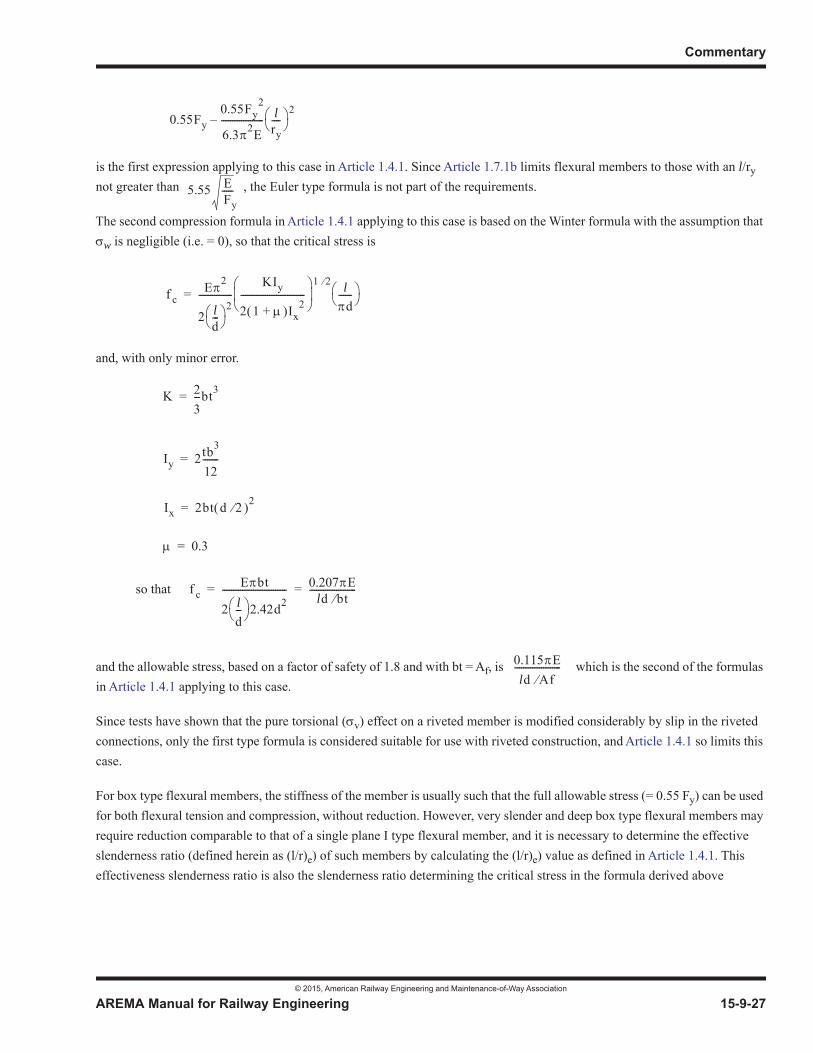
Commentary
© 2015, American Railway Engineering and Maintenance-of-Way Association
AREMA Manual for Railway Engineering 15-9-27
1
3
4
is the first expression applying to this case in Article 1.4.1. Since Article 1.7.1b limits flexural members to those with an l/rynot greater than , the Euler type formula is not part of the requirements.
The second compression formula in Article 1.4.1 applying to this case is based on the Winter formula with the assumption that
w is negligible (i.e. = 0), so that the critical stress is
and, with only minor error.
so that
and the allowable stress, based on a factor of safety of 1.8 and with bt = Af, is which is the second of the formulas in Article 1.4.1 applying to this case.
Since tests have shown that the pure torsional ( v) effect on a riveted member is modified considerably by slip in the riveted connections, only the first type formula is considered suitable for use with riveted construction, and Article 1.4.1 so limits this case.
For box type flexural members, the stiffness of the member is usually such that the full allowable stress (= 0.55 Fy) can be used for both flexural tension and compression, without reduction. However, very slender and deep box type flexural members may require reduction comparable to that of a single plane I type flexural member, and it is necessary to determine the effective slenderness ratio (defined herein as (l/r)e) of such members by calculating the (l/r)e) value as defined in Article 1.4.1. This effectiveness slenderness ratio is also the slenderness ratio determining the critical stress in the formula derived above
0.55Fy0.55Fy
2
6.3 2E------------------- l
ry----
2–
5.55 EFy-----
f cE 2
2 ld---
2---------------
KIy
2 1 Ix2+
-----------------------------1 2 l
d------=
K 23---bt3=
Iy 2tb3
12-------=
Ix 2bt d 2 2=
0.3=
f cE bt
2 ld--- 2.42d2
----------------------------- 0.207 Eld bt
---------------------= =
0.115 Eld Af
---------------------

Steel Structures
© 2015, American Railway Engineering and Maintenance-of-Way Association
15-9-28 AREMA Manual for Railway Engineering
for beams in which the pure torsion effect is negligible. This critical stress for box girders is calculated to be (Reference 41):
where J = torsional constant =
I, Sx, A, Iy and s/t defined in Article 1.4.1.
Equating these two values for fc:
and making the indicated substitutions, the value of the effective slenderness ratio shown in Article 1.4.1 is solved to be:
The allowable stress in bearing between rockers and rocker pins was adapted from editions prior to the 1969 edition and the low value of 0.375 Fy was retained to minimize pin wear. Pin wear had historically been a cause of trouble when higher values for this condition were permitted. Refer to Part 5 for additional information.
The allowable shears in A325 and A490 bolts are based on recommendations of the Research Council on Structural Connections of the Engineering Foundation. Also see Reference 86 and 117.
The allowable stress in bearing on expansion rollers and rockers was based on static and rolling tests on rollers and rockers (Reference 19 and 86). The average vertical pressures over calculated contact areas for loads substantially less than allowable design values are in excess of the yield point, causing a flow of the material. It was concluded that the resulting “spread” of the roller and base, measured parallel to the axis of the roller at points near the surfaces in contact, was the most satisfactory phenomenon to use in determining design values. Such “spreads” or deformations were measured in units of 0.001 to, per inch per 1,000 strokes, each stroke corresponding to a roller movement of 4 inches and an equal movement back. Design values according to the tests would give total deformations varying from about 3 units to less than 1.
9.1.4.2 WELD METAL (1994) R(2014)
The allowable stresses on weld metal specified in Article 1.4.2, Table 15-1-13 are close to those permitted by AWS D1.5.
f c1.56 2E
lr--
e
2--------------------=
f c lSx------- JGEly=
4A2
s t-----------
G E2 1 +---------------------=
1.56 2E
lr--
e
2--------------------
lSx------- JGEly=
lr--
e
1.105 lSx s t
AIy
1 +-----------------
------------------------------------------=
Commentary
© 2015, American Railway Engineering and Maintenance-of-Way Association
AREMA Manual for Railway Engineering 15-9-29
1
3
4
9.1.4.3 CAST STEEL (1994) R(2014)
In the 1969 edition, because of better control over casting practices, the allowable unit stresses for cast steel in bearing orcompression were increased from 0.9 to 1.0 of those for rolled steel, and for all other types of stress, from 2/3 to 3/4 those for rolled steel.
9.1.5 GENERAL RULES
9.1.5.4 THICKNESS OF MATERIAL (2011) R(2014)
a. The 0.335 inch thickness limitation was introduced in 1969 to accommodate the use of certain wide flange beam sections as timber stringer replacements given that the assumed life of a timber structure was less than the assumed life of a typical steel structure. It is not the intention of this article to preclude this application on timber trestles.
b. The usual design checks for a gusset plate and each member framing into the gusset plate are:
• Normal Loads on a Section (t Lw), often referred to as the Whitmore Section as shown in Figure 15-9-4, where Lw is the effective width and t is the thickness of the gusset plate.
• Block shear, for compression and tension loads.
• Shear on critical shear planes.
• Buckling on the average of L1, L2, L3, as shown in Figure 15-9-4 with buckling factor of k to be evaluated for the gusset plate (k might be greater than 1.0).
• All edge distance and end distance requirements for fasteners should be followed.
• Gusset plates should be as compact as possible.
• Check various critical sections using an acceptable method.
• Check fastener prying action.
• Each gusset plate is unique and must be designed based on specific forces, geometry and details.

Steel Structures
© 2015, American Railway Engineering and Maintenance-of-Way Association
15-9-30 AREMA Manual for Railway Engineering
For further information on bolted and riveted gusset plates see Reference 78. Design of gusset plates using the procedure in Section 13 of “Structural Steel Designers Handbook” Third Edition, edited by R L Brockenbrough and F S Merritt, written by Prickett, Leroy and Kulicki, provides a reasonable approach.
9.1.5.8 NET SECTION (2005) R(2014)
Net section is discussed by Chapin (Reference 37). He gives the history of this method of obtaining the net section of a riveted tension member to take account of the weakening effect of staggered open holes. He gives the rather complicated formula which represents the theoretically correct solution of the problem, and states that the simplified formula used in the recommended practices gives approximately the same results. The application of the formula to bolted fabrication and the 85% limit were based on later tests. A chart for use with the formula is included with his discussion.
9.1.5.9 CONNECTIONS AND SPLICES (2014)
e. In 2003, provisions to evaluate block shear were added to the Manual. Tests indicate that it is reasonable to add the yield strength on one plane(s) of a connection to the rupture strength on the other plane(s) of a connection to predict the block shear strength of a connection (References 10, 69, 118). Coefficients of 0.35 for shear yield and 0.55 for tensile yield were used.
Updates in 2014 included changing the coefficient for shear yield to the more conservative 0.30 for closer conformance with AISC and adding the factor Ubs (Reference 16). Examples illustrating the use of Ubs may be found in Reference 16.
Figure 15-9-4. Bolted and Riveted Gusset Plates
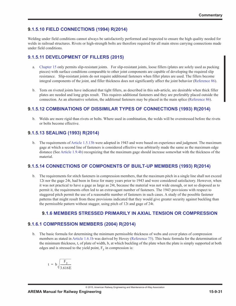
Commentary
© 2015, American Railway Engineering and Maintenance-of-Way Association
AREMA Manual for Railway Engineering 15-9-31
1
3
4
9.1.5.10 FIELD CONNECTIONS (1994) R(2014)
Welding under field conditions cannot always be satisfactorily performed and inspected to ensure the high quality needed for welds in railroad structures. Rivets or high-strength bolts are therefore required for all main stress carrying connections madeunder field conditions.
9.1.5.11 DEVELOPMENT OF FILLERS (2015)
a. Chapter 15 only permits slip-resistant joints. For slip-resistant joints, loose fillers (plates are solely used as packing pieces) with surface conditions comparable to other joint components are capable of developing the required slip resistance. Slip-resistant joints do not require additional fasteners when filler plates are used. The fillers become integral components of the joint, and filler thickness does not significantly affect the joint behavior (Reference 86).
b. Tests on riveted joints have indicated that tight fillers, as described in this sub-article, are desirable when thick filler plates are needed and long grips result. This requires additional fasteners and they are preferably placed outside the connection. As an alternative solution, the additional fasteners may be placed in the main splice (Reference 86).
9.1.5.12 COMBINATIONS OF DISSIMILAR TYPES OF CONNECTIONS (1993) R(2014)
b. Welds are more rigid than rivets or bolts. Where used in combination, the welds will be overstressed before the rivets or bolts become effective.
9.1.5.13 SEALING (1993) R(2014)
b. The requirements of Article 1.5.13b were adopted in 1943 and were based on experience and judgment. The maximum gage at which a second line of fasteners is considered effective was arbitrarily made the same as the maximum edge distance (See Article 1.9.4b) recognizing that the maximum gage should increase somewhat with the thickness of the material.
9.1.5.14 CONNECTIONS OF COMPONENTS OF BUILT-UP MEMBERS (1993) R(2014)
b. The requirements for stitch fasteners in compression members, that the maximum pitch in a single line shall not exceed 12t nor the gage 24t, had been in force for many years prior to 1943 and were considered satisfactory. However, when it was not practical to have a gage as large as 24t, because the material was not wide enough, or not so disposed as to permit it, the requirements often led to an extravagant number of fasteners. The 1943 provisions with respect to staggered pitch permit the use of a reasonable number of fasteners in such cases. A study of the possible fastener patterns that might result from these provisions indicated that they would give greater security against buckling than the permissible pattern without stagger, using pitch of 12t and gage of 24t.
9.1.6 MEMBERS STRESSED PRIMARILY IN AXIAL TENSION OR COMPRESSION
9.1.6.1 COMPRESSION MEMBERS (2004) R(2014)
b. The basic formula for determining the minimum permissible thickness of webs and cover plates of compression members as stated in Article 1.6.1b was derived by Hovey (Reference 75). This basic formula for the determination of the minimum thickness, t, of plate of width, b, at which buckling of the plate when the plate is simply supported at both edges and is stressed to the yield point, Fy in compression is:
t bFy
3.616E-----------------=
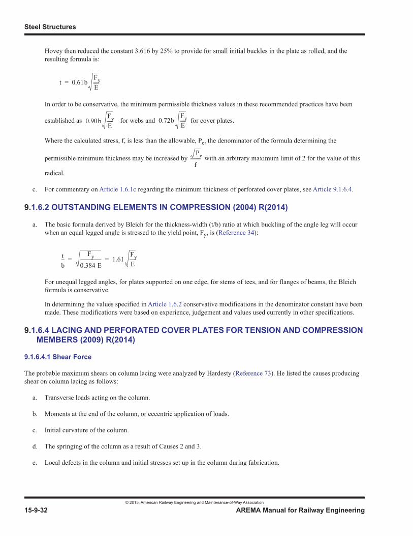
Steel Structures
© 2015, American Railway Engineering and Maintenance-of-Way Association
15-9-32 AREMA Manual for Railway Engineering
Hovey then reduced the constant 3.616 by 25% to provide for small initial buckles in the plate as rolled, and the resulting formula is:
In order to be conservative, the minimum permissible thickness values in these recommended practices have been
established as for webs and for cover plates.
Where the calculated stress, f, is less than the allowable, Pe, the denominator of the formula determining the
permissible minimum thickness may be increased by with an arbitrary maximum limit of 2 for the value of this
radical.
c. For commentary on Article 1.6.1c regarding the minimum thickness of perforated cover plates, see Article 9.1.6.4.
9.1.6.2 OUTSTANDING ELEMENTS IN COMPRESSION (2004) R(2014)
a. The basic formula derived by Bleich for the thickness-width (t/b) ratio at which buckling of the angle leg will occur when an equal legged angle is stressed to the yield point, Fy, is (Reference 34):
For unequal legged angles, for plates supported on one edge, for stems of tees, and for flanges of beams, the Bleich formula is conservative.
In determining the values specified in Article 1.6.2 conservative modifications in the denominator constant have been made. These modifications were based on experience, judgement and values used currently in other specifications.
9.1.6.4 LACING AND PERFORATED COVER PLATES FOR TENSION AND COMPRESSION MEMBERS (2009) R(2014)
9.1.6.4.1 Shear Force
The probable maximum shears on column lacing were analyzed by Hardesty (Reference 73). He listed the causes producing shear on column lacing as follows:
a. Transverse loads acting on the column.
b. Moments at the end of the column, or eccentric application of loads.
c. Initial curvature of the column.
d. The springing of the column as a result of Causes 2 and 3.
e. Local defects in the column and initial stresses set up in the column during fabrication.
t 0.61bFyE-----=
0.90bFyE----- 0.72b
FyE-----
Pe
f---------
tb---
Fy
0.384 E------------------- 1.61
FyE-----= =
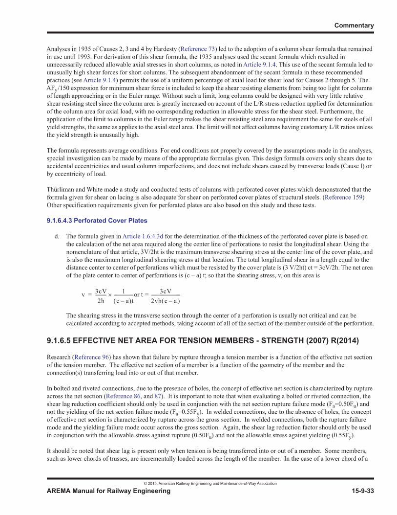
Commentary
© 2015, American Railway Engineering and Maintenance-of-Way Association
AREMA Manual for Railway Engineering 15-9-33
1
3
4
Analyses in 1935 of Causes 2, 3 and 4 by Hardesty (Reference 73) led to the adoption of a column shear formula that remained in use until 1993. For derivation of this shear formula, the 1935 analyses used the secant formula which resulted in unnecessarily reduced allowable axial stresses in short columns, as noted in Article 9.1.4. This use of the secant formula led to unusually high shear forces for short columns. The subsequent abandonment of the secant formula in these recommended practices (see Article 9.1.4) permits the use of a uniform percentage of axial load for shear load for Causes 2 through 5. The AFy/150 expression for minimum shear force is included to keep the shear resisting elements from being too light for columns of length approaching or in the Euler range. Without such a limit, long columns could be designed with very little relative shear resisting steel since the column area is greatly increased on account of the L/R stress reduction applied for determinationof the column area for axial load, with no corresponding reduction in allowable stress for the shear steel. Furthermore, the application of the limit to columns in the Euler range makes the shear resisting steel area requirement the same for steels of allyield strengths, the same as applies to the axial steel area. The limit will not affect columns having customary L/R ratios unlessthe yield strength is unusually high.
The formula represents average conditions. For end conditions not properly covered by the assumptions made in the analyses, special investigation can be made by means of the appropriate formulas given. This design formula covers only shears due to accidental eccentricities and usual column imperfections, and does not include shears caused by transverse loads (Cause l) or by eccentricity of load.
Thürliman and White made a study and conducted tests of columns with perforated cover plates which demonstrated that the formula given for shear on lacing is also adequate for shear on perforated cover plates of structural steels. (Reference 159)Other specification requirements given for perforated plates are also based on this study and these tests.
9.1.6.4.3 Perforated Cover Plates
d. The formula given in Article 1.6.4.3d for the determination of the thickness of the perforated cover plate is based on the calculation of the net area required along the center line of perforations to resist the longitudinal shear. Using the nomenclature of that article, 3V/2ht is the maximum transverse shearing stress at the center line of the cover plate, and is also the maximum longitudinal shearing stress at that location. The total longitudinal shear in a length equal to the distance center to center of perforations which must be resisted by the cover plate is (3 V/2ht) ct = 3cV/2h. The net area of the plate center to center of perforations is (c – a) t; so that the shearing stress, v, on this area is
The shearing stress in the transverse section through the center of a perforation is usually not critical and can be calculated according to accepted methods, taking account of all of the section of the member outside of the perforation.
9.1.6.5 EFFECTIVE NET AREA FOR TENSION MEMBERS - STRENGTH (2007) R(2014)
Research (Reference 96) has shown that failure by rupture through a tension member is a function of the effective net section of the tension member. The effective net section of a member is a function of the geometry of the member and the connection(s) transferring load into or out of that member.
In bolted and riveted connections, due to the presence of holes, the concept of effective net section is characterized by ruptureacross the net section (Reference 86, and 87). It is important to note that when evaluating a bolted or riveted connection, the shear lag reduction coefficient should only be used in conjunction with the net section rupture failure mode (Fa=0.50Fu) and not the yielding of the net section failure mode (Fa=0.55Fy). In welded connections, due to the absence of holes, the concept of effective net section is characterized by rupture across the gross section. In welded connections, both the rupture failuremode and the yielding failure mode occur across the gross section. Again, the shear lag reduction factor should only be used in conjunction with the allowable stress against rupture (0.50Fu) and not the allowable stress against yielding (0.55Fy).
It should be noted that shear lag is present only when tension is being transferred into or out of a member. Some members, such as lower chords of trusses, are incrementally loaded across the length of the member. In the case of a lower chord of a
v 3cV2h
---------- 1c a– t
------------------or t 3cV2vh c a–---------------------------==
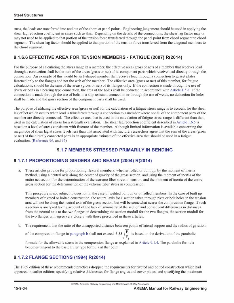
Steel Structures
© 2015, American Railway Engineering and Maintenance-of-Way Association
15-9-34 AREMA Manual for Railway Engineering
truss, the loads are transferred into and out of the chord at panel points. Engineering judgement should be used in applying theshear lag reduction coefficient in cases such as this. Depending on the details of the connections, the shear lag factor may ormay not need to be applied to that portion of the tension force transferred through the panel point from chord segment to chordsegment. The shear lag factor should be applied to that portion of the tension force transferred from the diagonal members to the chord segment.
9.1.6.6 EFFECTIVE AREA FOR TENSION MEMBERS - FATIGUE (2007) R(2014)
For the purpose of calculating the stress range in a member, the effective area (gross or net) of a member that receives load through a connection shall be the sum of the areas (gross or net) of its component parts which receive load directly through theconnection. An example of this would be an I-shaped member that receives load through a connection to gusset plates fastened only to the flanges and not the web of the member. The effective area (gross or net) of this member, for fatigue calculations, should be the sum of the areas (gross or net) of its flanges only. If the connection is made through the use of rivets or bolts in a bearing type connection, the area of the holes shall be deducted in accordance with Article 1.5.8. If the connection is made through the use of bolts in a slip-resistant connection or through the use of welds, no deduction for holes shall be made and the gross section of the component parts shall be used.
The purpose of utilizing the effective area (gross or net) for the calculation of a fatigue stress range is to account for the shearlag effect which occurs when load is transferred through a connection to a member where not all of the component parts of the member are directly connected. The effective area that is used in the calculation of fatigue stress range is different than thatused in the calculation of stress for a strength evaluation. The shear lag reduction coefficient described in Article 1.6.5 is based on a level of stress consistent with fracture of the member. Although limited information is available concerning the magnitude of shear lag at stress levels less than that associated with fracture, researchers agree that the sum of the areas (grossor net) of the directly connected parts is an appropriate estimate of the effective area that should be used in a fatigue evaluation. (Reference 96, and 97)
9.1.7 MEMBERS STRESSED PRIMARILY IN BENDING
9.1.7.1 PROPORTIONING GIRDERS AND BEAMS (2004) R(2014)
a. These articles provide for proportioning flexural members, whether rolled or built up, by the moment of inertia method, using a neutral axis along the center of gravity of the gross section, and using the moment of inertia of the entire net section for the determination of the extreme fiber stress in tension, and the moment of inertia of the entire gross section for the determination of the extreme fiber stress in compression.
This procedure is not subject to question in the case of welded built up or of rolled members. In the case of built up members of riveted or bolted construction, the neutral axis for a section taken through rivet or bolt holes in the tension area will not be along the neutral axis of the gross section, but will be somewhat nearer the compression flange. If such a section is analyzed taking account of the lack of symmetry of the section and consequent differences in distances from the neutral axis to the two flanges in determining the section moduli for the two flanges, the section moduli for the two flanges will agree very closely with those prescribed in these articles.
b. The requirement that the ratio of the unsupported distance between points of lateral support and the radius of gyration
of the compression flange in paragraph b shall not exceed is based on the derivation of the parabolic
formula for the allowable stress in the compression flange as explained in Article 9.1.4. The parabolic formula becomes tangent to the basic Euler type formula at that point.
9.1.7.2 FLANGE SECTIONS (1994) R(2014)
The 1969 edition of these recommended practices dropped the requirements for riveted and bolted construction which had appeared in earlier editions specifying relative thicknesses for flange angles and cover plates, and specifying the maximum
5.55 EFy-----
Commentary
© 2015, American Railway Engineering and Maintenance-of-Way Association
AREMA Manual for Railway Engineering 15-9-35
1
3
4
percentage of the total flange area permitted in the cover plates. These requirements had no theoretical basis, but had been included because of what had historically been considered good practice. Present requirements for the length of partial length cover plates in riveted and bolted construction control the stress at the end of the cover plate, which is a critical section forfatigue.
9.1.7.3 THICKNESS OF WEB PLATES (2004) R(2014)
a. The specified thickness of web plates for flexural members is based on work done by Hovey (Reference 75). Hovey showed that the buckling of the web of a flexural member on the compression side of the neutral axis can be prevented either by the use of horizontal (longitudinal) stiffeners or by making the web of such thickness that stability against buckling is ensured. Vertical (intermediate transverse) stiffeners are not effective in resisting buckling caused by bending. Assuming the actual extreme fiber stress in the compression flange is 0.55 Fy, and that the compression stress in the web adjacent to the flange is less than this by an assumed percentage, the ratio of the thickness of the web to the clear distance between flanges, for a web without horizontal stiffeners, to ensure the stability of the web against
flexural buckling may be expressed by the formula .
Where the extreme fiber stress in compression is less than the allowable, then the ratio may be modified as specified.
b. For web plates stiffened by a horizontal (longitudinal) stiffener located at 0.20 of the web depth from the compression flange, work by Rockey and Leggett (Reference 119) has shown that, to ensure the stability of the web against flexural buckling, the web plate thickness required is only 43% of that required without a horizontal stiffener. It is specified that the web plate thickness shall not be less than 1/2 that determined for a web plate without a horizontal stiffener.
9.1.7.4 FLANGE-TO-WEB CONNECTION OF PLATE GIRDERS (2009) R(2014)
b. The recommendation to use continuous, full penetration groove welds for the flange-to-web connection of open and non-composite, non-ballasted decks is to prevent fatigue cracking in the top flange welds from the direct application of cyclic wheel loads. Full penetration groove welds ensure complete fusion between flange and web. Fillet welds may crack through their throat from the transfer of repetitive concentrated loads unless they have been designed for that loading condition.
For ballasted, welded steel plate or composite concrete decks, and through plate girders, either continuous, partial joint or complete joint penetration groove welds or fillet welds can be used as the concentrated loads are distributed such that the loading on the flange and web plate is not as critical for fatigue. Any of these types of connections will provide comparable performance. When webs less than 1/2 inch thick are used, fillet welded connections are preferable as they result in less web out-of-plane distortion from weld shrinkage. Fillet welds on the bottom flange should never be subjected to concentrated wheel loads.
Fatigue cracking has been known to originate from the lack-of-fusion plane which exists between the web and flange joints where fillet welds were used in open and non-composite, non-ballasted decks. The driving force producing the cracking is from the direct application of wheel loads which apply vertical cyclic stresses to the welded joint perpendicular to the lack-of-fusion plane. Although the applied vertical cyclic stress ranges are compressive, the welds actually undergo cyclic tensile stress ranges due to the residual tensile stresses from welding. Previous editions of the manual required the flange-to-web joints be made using continuous, complete joint penetration (CJP) welds. Partial joint penetration (PJP) groove welds were acceptable if permitted by the engineer, though no guidance on how to design the PJP joint for fatigue was provided in manual. As a result, CJP were typically specified.
The provisions to include PJP groove welds at the flange-to-web weld in Article 1.7.4b were added to allow the use of the more economical weld details in lieu of the CJP welds previously required. When properly proportioned, PJP groove welds will perform as well as CJP groove welds to resist such cracking if sufficient penetration is achieved and/or if sufficient fillet reinforcement is provided. In such cases, the fatigue strength of the PJP weld subjected to
0.18FyE-----
Steel Structures
© 2015, American Railway Engineering and Maintenance-of-Way Association
15-9-36 AREMA Manual for Railway Engineering
transverse or vertical loads is controlled by weld toe cracking and not throat cracking. Hence, the performance will be the same as the CJP but with the lower cost PJP.
This can be achieved by using the equation in the provisions of Section 5.4 in Table 15-1-9. The costs to fabricate CJP are greater than PJP connections due to the increased requirements on inspection and increased overall fabrication costs.
If a PJP weld is used for the flange-to-web connection, the connection shall be considered a Fatigue Detail Category B’ for checking the longitudinal bending stresses in the girder.
9.1.7.8 WEB PLATE STIFFENERS (INTERMEDIATE TRANSVERSE AND LONGITUDINAL) (2012) R(2014)
a. Hovey showed that the ratio of web clear depth to thickness for which stiffeners are not needed is determined by the
formula , where Fys is the yield point in shear of the web material (Reference 75). With Fys = 0.636 Fy, the
formula became . The formula , used in Article 1.7.8, makes allowance for lack of flatness in the
web plate.
Where stiffeners are required, their spacing is dependent on the web thickness and the shearing stress in the web. The development of the formula is based on work by Moisseiff and Leinhard and is based on a factor of safety of 1.5 against buckling of the web (Reference 95). This factor of safety is lower than the basic factor of safety generally used throughout these recommended practices, but is considered adequate because elastic buckling of the web does not cause failure. When elastic buckling of the web occurs, its share of additional diagonal compression is transferred to the flange and vertical (intermediate transverse) stiffeners.
The 96 inches maximum spacing of the stiffeners is specified in order to provide stiffeners at reasonably close intervals so as to aid in eliminating the effect of any small out of flatness that may exist in the web. The 96 inch maximum spacing is based on work done by Basler indicating that for fabrication, handling and erection purposes the maximum stiffener spacing should not exceed 260t, where t is the web thickness in inches (Reference 32). The distance between vertical (intermediate transverse) stiffeners shall not exceed the distance between the flanges (web depth) because the
formula for stiffener spacing, , is developed from the theory of elastic stability with this assumption (i.e.
critical buckling coefficient in shear always less than 9.35).
The equation for minimum required moment of inertia “I” of the transverse stiffener is a modification of that developed by Bleich (Reference 34). In editions of the Manual prior to 2005 the term “da”, the actual clear distance between intermediate transverse stiffeners, was used in the formula for “I” instead of the present “d”. The effect of using “da”was that the stiffeners were sized to develop the elastic shear buckling capacity of the web for that “da”. For various reasons, transverse stiffeners are sometimes spaced closer than the spacing required by Article 1.7.8a. This close spacing results in a web shear buckling capacity (based on elastic behavior) much greater than the web shear yielding capacity. Hence, for such cases of arbitrary stiffener spacing, the stiffener sizes computed from the formula for “I” were excessive. The use of “d” in the equation for “I” results in more consistent stiffener sizes for girders having stiffener spacings dependent on other factors in addition to shear.
When Bleich’s work was incorporated into the Manual the limits were omitted. Under certain circumstances where stiffeners are required, and the shear stress is low, the value of “I” may be negative for values D/d < 1. The equation is valid only for D/d between 1 and 5, so these limits were added to the Manual in 2012. It is possible that the ratio of D/d given the other constraints in the article will result in a value less than 1, in which case the limitation yields a minimum stiffener.
4.83EFys
--------------
2.75 EFy----- 2.12 E
Fy-----
1.95t ES---

Commentary
© 2015, American Railway Engineering and Maintenance-of-Way Association
AREMA Manual for Railway Engineering 15-9-37
1
3
4
f. The web plate depth criteria of relates to the web plate depth required to preclude flexural elastic buckling
of the web plate without horizontal (longitudinal) stiffeners.
g. The recommended practice for placing the centerline of the longitudinal stiffener at 1/5 the web depth from the compression flange is from work by Rockey and Legett (Reference 119) showing this to be near optimum location to resist flexural buckling of a simply supported plate. Where longitudinal and intermediate transverse stiffeners intersect, the preferred detail is to interrupt the transverse stiffener since terminations in the longitudinal stiffener createdetails that are more prone to fatigue. Article 9.1.10.2g provides additional guidance and preferred detailing practices for intersecting stiffeners.
h. The recommended practice for longitudinal stiffener size is taken as a reasonable upper bound for girders of practical proportions based on the work by Dubas (Reference 46).
i. The recommended practice for the thickness requirements for longitudinal stiffeners is based on the local buckling behavior of the stem of a tee section.
9.1.7.9 COMPOSITE STEEL AND CONCRETE SPANS (2008) R(2014)
The two types of shear connectors included, i.e. manually welded channels and automatically welded studs, are those most commonly used (Reference 133). Other types may be satisfactory.
Recommended practice requirements are generally based on performance, allowing the manufacturer and fabricator considerable leeway as to details and procedures.
9.1.7.9.2 Basic Design Assumptions (1986) R(2005)
and9.1.7.9.3.1 Design Force for Shear Connectors
The calculations for the value of the horizontal shear between the steel beam and the concrete slab in Article 1.7.9.2 j involve the determination of the values Sm of the maximum horizontal shear and the value of Sr of the range of the horizontal shear.
The effect of repeated stress variations was studied at Lehigh University by making fatigue tests on composite spans (Reference 133). The results indicated that the range of horizontal shear resulting from live load and impact load, rather than the maximum horizontal shear from dead load combined with live load and impact load, controls fatigue capacity. The allowable design load per shear connector, based on maximum range as specified in Article 1.7.9.3.1, is therefore less than is specified in that same article for maximum shear.
It is noted that the fatigue check Article 1.7.9.3.1(c) is different from that required in Articles 1.7.9.3.1(a) and 1.7.9.3.1(b).The checks in Articles 1.7.9.3.1(a) and 1.7.9.3.1(b) are to ensure that fatigue cracking in the weld used to attach the shear connector to the flange does not occur through the weld throat due to cyclic shear stresses.
The requirement to check fatigue in the base metal of the member to which the shear connectors are attached (Article 1.3.13)is to ensure toe cracking does not develop at the weld and lead to cracking of the member due to primary bending stress range. The shear connectors are considered a short attachment on the flange. It is unlikely this check will ever control, as live loadstress ranges will be very small due to the high location of the neutral axis.
4.18 Ef--- t
Steel Structures
© 2015, American Railway Engineering and Maintenance-of-Way Association
15-9-38 AREMA Manual for Railway Engineering
9.1.8 FLOOR MEMBERS AND FLOORBEAM HANGERS
9.1.8.3 END CONNECTIONS OF FLOOR MEMBERS (1993) R(2014)
The requirements for the connection angles of stringers were developed by Wilson after a study of the bending stresses in such angles resulting from the lengthening of the bottom chords of through truss bridges under live and impact loads, and from the deflection of the stringers themselves under such loadings (Reference 160, 165).
Although the flexural stresses in the stringer and connection angles resulting from the lengthening of the bottom chord of through truss bridges are small, making these connection angles more flexible reduces the rather large bending stresses in the floorbeams resulting from bottom chord elongation.
The flexural stress in the top portion of the leg of the stringer connection angles connected to the floorbeam may be high as aresult of the deflection of the stringer under load and in the case of thick angles may cause fatigue cracks. For a given deflection in the top portion of the angle, the stress induced in the angle leg varies directly with the angle thickness, and inversely as the square of the gage. This deflection is essentially proportional to the length of the stringer. These three factorshave been combined empirically in the requirements of this article.
9.1.9 RIVETED AND BOLTED CONSTRUCTION
9.1.9.4 EDGE DISTANCE OF FASTENERS (2005) R(2011)
a. Based on a review of various textbooks, specifications, and design guides it has been found that there is not a solid “engineering” reason for the various limits on edge distance. The limits which have been set are more related to detailing issues. The rationale for various edge conditions is as follows:
• Sheared edges
From the Cyclopedia of Civil Engineering, Vol 3, Steel Construction, 1920, a reason for a limit on edge distance is given based on the tendency of the material to bulge between the edge of the hole and the edge of the plate due to the punching process. To prevent this, it is stated that a minimum edge distance is required. The limit is decreased for smaller size rolled shapes only to allow punching in the material rather than for any engineering reason. The third edition of the AISC LRFD Manual of Steel Construction (2003) indicates similar reasoning in the Commentary contained in Chapter J of that publication. (References 15, and 29)
• Rolled edges of plates, shapes, bars or thermally cut edges
Limitations on the clearance for making the hole, as well as the fact that the rolled and thermally cut edges have a much better tolerance in terms of workmanship, justifies a lower limit for these type edges. The limit is reduced for flanges of beams and channels to 1.25 times the diameter of the fastener, but only because there may be clearance issues with the equipment used to make the hole in these sections with smaller flanges. Similar reductions are also permitted by the AISC Manual. (Reference 15)
• Fatigue
The difference in the edge distance requirements is not related to fatigue. Although a sheared edge is almost always a lower quality than a rolled or thermally cut edge, the fatigue strength of a plate that is sheared cannot be improved by slightly increasing the edge distance. The micro cracks produced by the process are present regardless and under large enough cyclic stresses will grow into fatigue cracks. For a base metal condition to apply at the gross section of the element (i.e., Category A), there are specific surface quality standards that must be met as per AREMA Table 15-1-9, AASHTO LRFD, and others. Rolled edges will typically meet these criteria. For thermally cut edges, it may be necessary to grind the surface of the cut to meet the required surface quality. However, sheared edges will
Commentary
© 2015, American Railway Engineering and Maintenance-of-Way Association
AREMA Manual for Railway Engineering 15-9-39
1
3
4
not meet the requirements due to the destructive nature of shearing the plate material, and some surface preparation will be required. (References 4, and 86)
9.1.9.6 FASTENERS IN INDIRECT SPLICES (2015)
For splices with fill plates, additional rivet rows are required at the ends of the plates to ensure an adequate connection. Forbolted connections, slip-resistant joints are utilized in all connections.
9.1.10 WELDED CONSTRUCTION
9.1.10.1 TRANSITION OF THICKNESS OR WIDTHS IN WELDED BUTT JOINTS (2012) R(2014)
The requirements of Article 1.10.1 are similar to those in AWS D1.5 with additions to cover flexural conditions, and relocation of the weld to be outside the end of transition on the radius of the wider plate.
9.1.10.2 PROHIBITED TYPES OF JOINTS AND WELDS (2008) R(2014)
Because of fatigue considerations, several types of joints and welds are added to types prohibited by AWS D1.5.
g. Highly Constrained Joints:
Welded structures are to be detailed to avoid conditions that create highly constrained joints and crack-like geometric discontinuities that are susceptible to Constraint-Induced-Fracture (CIF). Avoid intersecting welds by using a preferred detail (see Figure 15-9-5) or by using high-strength bolted connections. However, the avoidance of intersecting welds is not intended to apply to the intersection of flange splice welds with flange-to-web welds.
Constraint-Induced-Fracture is a form of brittle fracture that can occur without any perceptible fatigue crack growth and more importantly, without any apparent warning. This type of failure was documented during the Hoan Bridge failure investigation (Reference 163) as well as in other bridges that have exhibited very similar fractures (References 42 & 43). Criteria have been developed to identify and retrofit bridges susceptible to this failure mode (References 42& 93).
Although it is common to start and stop an attached element parallel to primary stress (e.g., gusset plate or longitudinal stiffener) when intersecting a full-depth transverse member, the detail is more resistant to fracture (and fatigue) if the attachment parallel to the primary stresses is continuous and the transverse connection is discontinuous. (See Figure 15-9-5 and Figure 15-9-6)
High-strength bolted connections are not susceptible to Constraint-Induced-Fracture and should be considered where practical and economical.
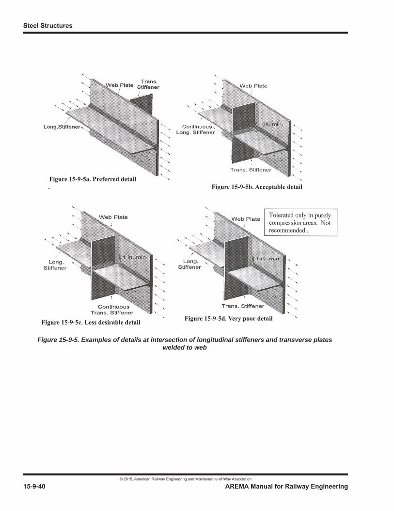
Steel Structures
© 2015, American Railway Engineering and Maintenance-of-Way Association
15-9-40 AREMA Manual for Railway Engineering
Figure 15-9-5a. Preferred detailFigure 15-9-5b. Acceptable detail
Figure 15-9-5c. Less desirable detail Figure 15-9-5d. Very poor detail
Figure 15-9-5. Examples of details at intersection of longitudinal stiffeners and transverse plates welded to web
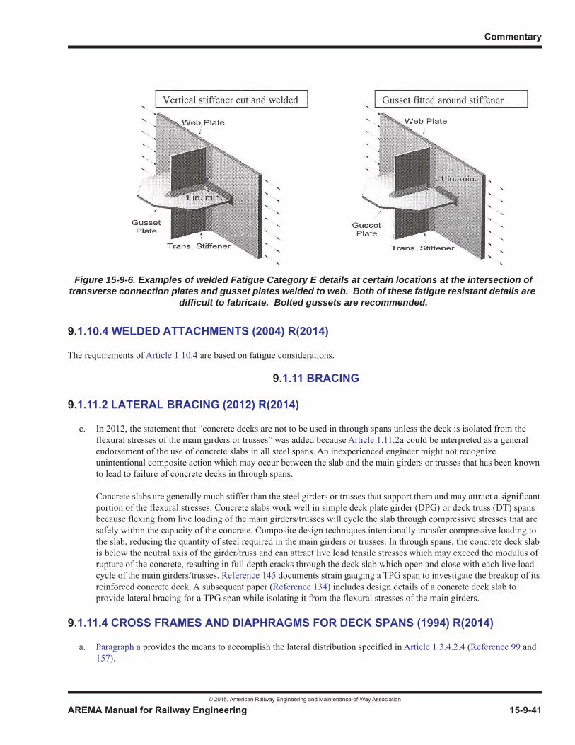
Commentary
© 2015, American Railway Engineering and Maintenance-of-Way Association
AREMA Manual for Railway Engineering 15-9-41
1
3
4
9.1.10.4 WELDED ATTACHMENTS (2004) R(2014)
The requirements of Article 1.10.4 are based on fatigue considerations.
9.1.11 BRACING
9.1.11.2 LATERAL BRACING (2012) R(2014)
c. In 2012, the statement that “concrete decks are not to be used in through spans unless the deck is isolated from the flexural stresses of the main girders or trusses” was added because Article 1.11.2a could be interpreted as a general endorsement of the use of concrete slabs in all steel spans. An inexperienced engineer might not recognize unintentional composite action which may occur between the slab and the main girders or trusses that has been known to lead to failure of concrete decks in through spans.
Concrete slabs are generally much stiffer than the steel girders or trusses that support them and may attract a significant portion of the flexural stresses. Concrete slabs work well in simple deck plate girder (DPG) or deck truss (DT) spans because flexing from live loading of the main girders/trusses will cycle the slab through compressive stresses that are safely within the capacity of the concrete. Composite design techniques intentionally transfer compressive loading to the slab, reducing the quantity of steel required in the main girders or trusses. In through spans, the concrete deck slab is below the neutral axis of the girder/truss and can attract live load tensile stresses which may exceed the modulus of rupture of the concrete, resulting in full depth cracks through the deck slab which open and close with each live load cycle of the main girders/trusses. Reference 145 documents strain gauging a TPG span to investigate the breakup of its reinforced concrete deck. A subsequent paper (Reference 134) includes design details of a concrete deck slab to provide lateral bracing for a TPG span while isolating it from the flexural stresses of the main girders.
9.1.11.4 CROSS FRAMES AND DIAPHRAGMS FOR DECK SPANS (1994) R(2014)
a. Paragraph a provides the means to accomplish the lateral distribution specified in Article 1.3.4.2.4 (Reference 99 and 157).
Figure 15-9-6. Examples of welded Fatigue Category E details at certain locations at the intersection of transverse connection plates and gusset plates welded to web. Both of these fatigue resistant details are
difficult to fabricate. Bolted gussets are recommended.

Steel Structures
© 2015, American Railway Engineering and Maintenance-of-Way Association
15-9-42 AREMA Manual for Railway Engineering
Out of plane bending may result from restraint provided by cross frames or diaphragms where there is differential deflection of adjacent beams or girders. This may be expected to occur in spans with curved alignment, skews or multiple tracks and has also been observed in single track spans, without skew, on tangent alignment. Out-of-plane bending may cause high stresses in non-stiffened web gaps, unless rigid type connections are provided to stabilize these gaps.
b. Determination of whether a cross frame or diaphragm should be used is covered by paragraph b.
c. Requirements for diaphragms are specified in paragraph c to assure suitable lateral distribution of live load.
d-g. Paragraph d, paragraph e, paragraph f and paragraph g concern the spacing of cross frames and diaphragms for various types of deck construction. Spacing of 18 feet for cross frames and diaphragms in open deck construction has been specified since 1920; has been found to be satisfactory; and is used as a guide in specifying the spacing of these members for spans where steel plate, timber or precast concrete decking is utilized in ballasted deck construction and no top lateral bracing is used, as well as for spans with poured in place decking. The lack of lateral bracing requires close spacing of these members, whereas poured in place concrete decking will allow greater spacing, as evidenced by tests conducted at the University of Illinois on diaphragms for highway deck spans (Reference 99 and 157).
h. The diaphragms required in paragraph h are primarily for tying the transverse beams together and to some extent for distributing loads longitudinally.
9.1.12 PINS AND PIN-CONNECTED MEMBERS
9.1.12.1 PINS (2015)
a. Normalizing and tempering is the preferred method although heat treatment by annealing, or normalizing alone, may be acceptable in some cases.
b. The hole may be drilled before or after treatment.
c. Historically, recessed pin nuts were available in cast steel for pins up to 24-inches in diameter. Currently, the availability of pin nuts for this use is limited to a maximum of ten-inch diameter pins. For pins over ten inches in diameter, the preferred practice is for the pin to be held in place by a recessed cap at each end and secured by a fastener passing through the caps and through the bored hole in the pin. (References 11, 88)
9.1.13 CONTINUOUS AND CANTILEVER STEEL STRUCTURES
9.1.13.6 UPLIFT (2015)
Uplift should be avoided whenever possible, however when there is a potential for uplift, adequate anchorage must be provided. Anchorage includes anchor bolts, anchorage details on the span, and substructure self-weight. If there is insufficientmass in the substructure consideration may be given to providing a counterweight mass or rock anchors to bedrock.
9.1.13.8 LONGITUDINAL STIFFENERS (2010) R(2014)
A continuously welded stiffener is best for design and performance, but at the intersection of two stiffeners continuity of onemust be sacrificed. In such cases, it is generally better to interrupt the transverse stiffener since terminations in the longitudinal stiffener create details that are more prone to fatigue. For continuous or cantilever spans, however, the intersection between longitudinal stiffeners and transverse bearing stiffeners are an exception since bearing stiffener continuityis necessary for bearing loads and fatigue demand on the longitudinal stiffener termination detail is lower at bearing locations.Article 9.1.10.2g provides additional guidance and preferred detailing practices for intersecting stiffeners.

Commentary
© 2015, American Railway Engineering and Maintenance-of-Way Association
AREMA Manual for Railway Engineering 15-9-43
1
3
4
9.1.14 FRACTURE CRITICAL MEMBERS
9.1.14.1 SCOPE (2015)
Section 1.14, Fracture Critical Members is used as an extension of and supplement to the current requirements for materials, fabrication, welding, inspection and testing throughout Chapter 15, Steel Structures and the AWS Specifications. The implementation of the AWS D1.5 Fracture Control Plan for Fracture Critical Members helps to ensure that a steel bridge with critical tension components will serve a useful and serviceable life over the period intended in the original design. Some bridges do not have fracture critical members. However, it is most important to recognize them when they do exist. The Fracture Control Plan should not be used indiscriminately by designers to circumvent good engineering practice.
The following commentary applies to the provisions of D1.5 Clause 12 FCP as applied to railroad bridges:
Repair Welding [AWS D1.5]
Repair welding consists of deposition of additional weld metal to correct a surface condition, such as insufficient throat or undercut, or procedures which require removal of weld or base metal preparatory to correcting defects in materials or workmanship. The latter are divided into noncritical and critical repairs as determined by type and size of defect. Documentation of critical repair welding is required. This is to enable these areas to be given special attention when inspections are made after the bridge is in service.
Because virtually all weld repairs are made under conditions of high restraint, the minimum preheat/interpass temperatures requirements are generally higher than specified for the original welding.
9.1.14.2 DEFINITIONS (2013)
a. Fracture Critical Members (FCM) are defined as those tension members or tension components of members whose failure would be expected to result in collapse of the bridge or inability of the bridge to perform its design function. The identification of such components must, of necessity, be the responsibility of the bridge designer since virtually all bridges are inherently complex and the categorization of every bridge and every bridge member is impossible. However, to fall within the fracture critical category, the component must be in tension. Further, a fracture critical member may be either a complete bridge member or it may be a part of a bridge member.
b. Some examples of critical complete bridge members are girders of two-girder bridges and tension chords in truss bridges, provided a failure would cause loss of serviceability of the bridge. Some bridges do not depend on any single member, be it in tension or in compression, for structural integrity. Critical tension components of structures usually occur in flexural members. The tension flange of a flexural member is a critical component if a failure of the specific flexural member would cause loss of serviceability of the bridge. The web of a flexural member, adjacent to the tension flange, can be a critical component. Bearing sole plates welded to the tension flange are exempted because they are located in regions of low tensile stress. By extension, bearing components welded to the sole plate are likewise exempted from the requirements for FCMs.
Members or member components whose failure would not cause the bridge to be unserviceable are not considered fracture critical. Compression members and member components in compression may, in themselves, be critical but do not come under the provisions of this Plan. Compression components do not fail by crack formation and extension but rather by yielding or buckling. Similarly, riveted and bolted members, even though in tension, may not come under the provisions of this Plan. The Plan provides for additional quality of material and provides for increased care in the fabrication and use of the materials to lessen the probability of fracture of tension components from crack formation and extension under static and fatigue loading.

Steel Structures
© 2015, American Railway Engineering and Maintenance-of-Way Association
15-9-44 AREMA Manual for Railway Engineering
9.1.14.3 DESIGN AND REVIEW RESPONSIBILITIES (1997) R(2008)
a. A critical part of any complete Fracture Control Plan must deal with design and detailing. These two sections are not addressed in Section 1.14, Fracture Critical Members or in this commentary primarily because they are already included in other parts of this chapter. Fatigue requirements are extensively covered in Article 1.3.13 and, where necessary, are made more conservative for fracture critical members (see Article 1.3.13i). Fatigue categories for various bridge details also are extensively covered. However, it remains a prime responsibility of the designer to examine each detail in the bridge for compliance with the fatigue requirements and to ensure that the detailing will allow effective joining techniques and non-destructive testing of all welded joints. It is emphasized that the Fracture Control Plan must begin with the designer and that without proper design, details and specifications, the Plan will fail.
b. The designer is the only one with sufficient knowledge of the design to determine if fracture critical members are present and to specifically delineate those members or member components. It is, therefore, his responsibility to designate on the plans those members or member components which are fracture critical. Further, he also is responsible for the review of the shop drawings to determine whether the plans and specifications have been properly interpreted and that the fracture critical members are identified and properly fabricated.
9.1.14.5 NOTCH TOUGHNESS OF STEEL IN FRACTURE CRITICAL MEMBERS (2006) R(2008)
For comments relating to Table 15-1-14 see Article 9.1.2.1.
The notch toughness requirements for steels in railroad bridges are similar to those used in steel highway bridges as specifiedby AASHTO. The requirements developed by AASHTO were adopted after considerable research and deliberation between representatives of the AASHTO Subcommittees on Bridges and on Materials, the Federal Highway Administration, the American Iron and Steel Institute, the American Institute of Steel Construction and various consultants. These requirements were based on numerous technical considerations that include the following:
a. An understanding of the effects of constraint and temperature on the fracture toughness behavior of steels that were established by testing fracture mechanics specimens.
b. An understanding of the effects of rate of structural loading on the fracture toughness behavior of structural steels.
c. The development of a correlation between impact fracture toughness values (KId obtained by testing fracture toughness type specimens under impact loading) and impact energy absorption for Charpy V-notch (CVN) impact specimens.
d. Specification of CVN impact toughness values that ensure elastic-plastic initiation behavior for fracture of fatigue cracked specimens subjected to minimum operating temperatures and maximum in-service rates of loading.
e. A verification of the selected toughness values by the testing of fabricated bridge girders that were subjected to the maximum design fatigue life, followed by testing at the minimum operating temperature and the maximum in-service rate of loading.
f. An awareness of the extensive satisfactory service experience with steels in bridges and an understanding of the factors that have occasionally led to brittle fractures in bridges.
The safety and reliability of steel bridges are governed by material properties, design, fabrication, inspection, erection and usage. Both the AASHTO and AREMA Fracture Control Plans recognize that attention to all of these factors is essential and that excessive attention to any single item will not necessarily overcome the effects of a deficiency in any other item.
Neither the AASHTO nor the AREMA fracture toughness requirements are sufficient to prevent brittle fracture propagation under certain possible combinations of poor design, fabrication or loading conditions. To accomplish that fact would require

Commentary
© 2015, American Railway Engineering and Maintenance-of-Way Association
AREMA Manual for Railway Engineering 15-9-45
1
3
4
intermediate or upper-shelf dynamic toughness levels (also called crack arrest) and these levels of fracture-toughness are not needed to ensure the safety and reliability of the steel bridges.
The general difference in initiation and propagation behavior as related to fracture toughness test results is shown schematically in Figure 15-9-7. The curve labeled “static” refers to the fracture toughness obtained in a KId test under conditions of slow loading. (The curve for intermediate loading rate tests, which are extremely complex to run, would be shifted slightly to the right of the static curve. The AASHTO material toughness requirements were developed using an intermediate loading rate found applicable to actual bridge structures.) The impact curve is from KId or other dynamic test under conditions of impact loading. The difference between these two is the temperature shift, which is a function of yield strength for structural steels. In an actual structure loaded at temperature A, initiation may be static and propagation dynamic.However, there is no apparent difference between the two because both initiation and propagation are by cleavage. If a similar structure is loaded slowly to failure at temperature B, there will be some localized shear and a reasonable level of static fracture toughness at the initiation of failure. However, for rate sensitive materials, such as structural steels used in bridges,once the crack has initiated, the notch toughness is characterized by the dynamic toughness level on the impact curve and the fracture appearance for the majority of the fracture surface is cleavage. If the structure is loaded slowly to fracture initiation at temperature C, the initiation characteristics will be full shear initiation with a high level of plane stress, crack toughness Kc.However, the fracture surface of the running crack may still be predominately cleavage, but with some amount of shear as shown in the lower impact curve at temperature C in Figure 15-9-7.
The use of impact or dynamic fracture tests in fracture control would predict no difference in actual resistance to fracture between temperatures A and B and only a modest difference between B and C. In fact, however, there is a considerable increase in resistance to fracture initiation between A and B and between B and C, as is indicated by slow loading tests such asKIc or crack opening displacement tests. However, there is essentially no difference in the resistance to fracture propagation (i.e., crack arrest behavior) between A and B, and the difference between B and C is modest. Thus, to prevent brittle fracture propagation in a structure by using material toughness alone (i.e., without proper control of design, fabrication, inspection andusage), the impact toughness must be quite high, e.g., approaching full shear propagation behavior temperature D. Even then, there may be situations where crack growth still occurs.
Figure 15-9-7. Schematic Showing Relation Between Static and Dynamic Fracture Toughness
Steel Structures
© 2015, American Railway Engineering and Maintenance-of-Way Association
15-9-46 AREMA Manual for Railway Engineering
In summary, application of the AREMA material toughness requirements should provide a high level of elastic-plastic or plastic initiation behavior for steels with fatigue cracks loaded to maximum in-service rates of loading at the minimum servicetemperature. Because the AREMA Fracture Control Plan addresses all aspects that may lead to brittle fractures or fatigue failure (i.e., material properties, design, fabrication, inspection, erection and usage), these material toughness requirementsshould be satisfactory in the context of the total AREMA Fracture Control Plan.
The prime focus on Fracture Critical Members must be on quality of the material and fabrication. Using low fatigue resistant details should be avoided. Category E and E’ details shall not be used on Fracture Critical Members, and Category D details shall be discouraged and used only with caution.
PART 3 FABRICATION
9.3.1 GENERAL
9.3.1.6 THERMAL CUTTING, COPES, AND ACCESS HOLES (2009)
There are a number of thermal cutting techniques that are suitable for steel railroad bridge fabrication including, primarily, oxyfuel cutting and plasma cutting. Plasma cutting is generally preferred by fabricators because it is faster and offers improved quality (such as squarer corners, less hardness variability, and less distortion), but it is limited to thinner sections.The thickness limit depends upon the equipment, but typically about two inches is the reasonable thickness limit for plasma cutting. The provisions of this paragraph are similar to those in the AASHTO/AWS D1.5 Bridge Welding Code.
9.3.1.8 PLANING SHEARED EDGES (1994) R(2008)
Any sheared edge may have incipient cracks resulting from the shearing operation, which literally tears the material apart. Since such cracks might be harmful, the requirements for edge planing of sheared material have been included in these recommended practices and other specifications for many years.
The planing requirements need not be applied to thin A 36 material because the shearing operation does not produce structurally damaging defects therein.
9.3.1.18 BENT PLATES (2000) R(2008)
In fabrication, plates are often bent to a radius in a press brake or die. When conducted at room temperature, these processesare known as “cold bending”. To avoid cracking the plate during bending, it is necessary to adopt a suitable minimum inside bend radius, which typically varies with plate thickness and grade. Over the years, many new grades of steel have come into existence. A concern in the steel industry was that current limits dealing with this subject may not have been developed on a consistent basis. As a result, the American Iron and Steel Institute (AISI) initiated a project to develop rational limits for cold bending plates.
Initially, AISI retained Concurrent Technologies Corporation (CTC) to conduct an experimental research program, augmented by inelastic analysis, to investigate the forming characteristics of five plate steels. At the conclusion of that effort in January1997, AISI then retained R. L. Brockenbrough & Associates to extend the CTC findings to all steel plate specifications referenced in ASTM A6. That work was accomplished and reported in the document “Fabrication Guidelines for Cold Bending” dated June 29, 1998.
ASTM A6 has adopted the recommendations of this work as well as some supplemental workmanship language for achieving quality bent plates. Article 3.1.18 Bent Plates, is derived from both the “Fabrication Guidelines for Cold Bending” and the ASTM A6 document.
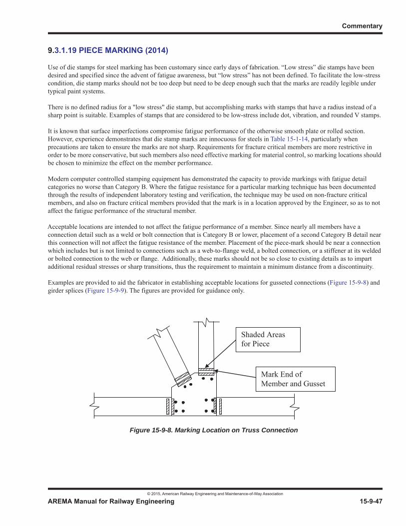
Commentary
© 2015, American Railway Engineering and Maintenance-of-Way Association
AREMA Manual for Railway Engineering 15-9-47
1
3
4
9.3.1.19 PIECE MARKING (2014)
Use of die stamps for steel marking has been customary since early days of fabrication. “Low stress” die stamps have been desired and specified since the advent of fatigue awareness, but “low stress” has not been defined. To facilitate the low-stress condition, die stamp marks should not be too deep but need to be deep enough such that the marks are readily legible under typical paint systems.
There is no defined radius for a "low stress" die stamp, but accomplishing marks with stamps that have a radius instead of a sharp point is suitable. Examples of stamps that are considered to be low-stress include dot, vibration, and rounded V stamps.
It is known that surface imperfections compromise fatigue performance of the otherwise smooth plate or rolled section. However, experience demonstrates that die stamp marks are innocuous for steels in Table 15-1-14, particularly when precautions are taken to ensure the marks are not sharp. Requirements for fracture critical members are more restrictive in order to be more conservative, but such members also need effective marking for material control, so marking locations should be chosen to minimize the effect on the member performance.
Modern computer controlled stamping equipment has demonstrated the capacity to provide markings with fatigue detail categories no worse than Category B. Where the fatigue resistance for a particular marking technique has been documented through the results of independent laboratory testing and verification, the technique may be used on non-fracture critical members, and also on fracture critical members provided that the mark is in a location approved by the Engineer, so as to not affect the fatigue performance of the structural member.
Acceptable locations are intended to not affect the fatigue performance of a member. Since nearly all members have a connection detail such as a weld or bolt connection that is Category B or lower, placement of a second Category B detail near this connection will not affect the fatigue resistance of the member. Placement of the piece-mark should be near a connection which includes but is not limited to connections such as a web-to-flange weld, a bolted connection, or a stiffener at its weldedor bolted connection to the web or flange. Additionally, these marks should not be so close to existing details as to impart additional residual stresses or sharp transitions, thus the requirement to maintain a minimum distance from a discontinuity.
Examples are provided to aid the fabricator in establishing acceptable locations for gusseted connections (Figure 15-9-8) and girder splices (Figure 15-9-9). The figures are provided for guidance only.
Shaded Areas for Piece
Mark End of Member and Gusset
Figure 15-9-8. Marking Location on Truss Connection
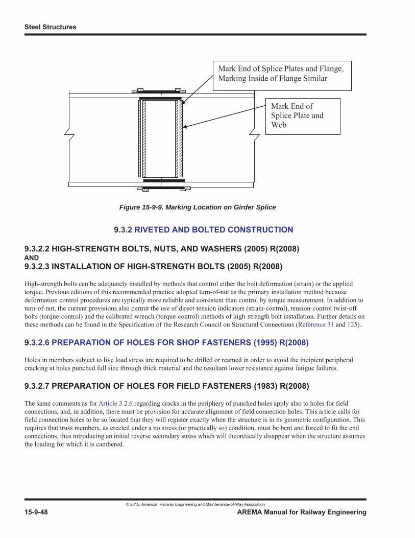
Steel Structures
© 2015, American Railway Engineering and Maintenance-of-Way Association
15-9-48 AREMA Manual for Railway Engineering
9.3.2 RIVETED AND BOLTED CONSTRUCTION
9.3.2.2 HIGH-STRENGTH BOLTS, NUTS, AND WASHERS (2005) R(2008)AND9.3.2.3 INSTALLATION OF HIGH-STRENGTH BOLTS (2005) R(2008)
High-strength bolts can be adequately installed by methods that control either the bolt deformation (strain) or the applied torque. Previous editions of this recommended practice adopted turn-of-nut as the primary installation method because deformation control procedures are typically more reliable and consistent than control by torque measurement. In addition to turn-of-nut, the current provisions also permit the use of direct-tension indicators (strain-control), tension-control twist-offbolts (torque-control) and the calibrated wrench (torque-control) methods of high-strength bolt installation. Further details onthese methods can be found in the Specification of the Research Council on Structural Connections (Reference 31 and 125).
9.3.2.6 PREPARATION OF HOLES FOR SHOP FASTENERS (1995) R(2008)
Holes in members subject to live load stress are required to be drilled or reamed in order to avoid the incipient peripheral cracking at holes punched full size through thick material and the resultant lower resistance against fatigue failures.
9.3.2.7 PREPARATION OF HOLES FOR FIELD FASTENERS (1983) R(2008)
The same comments as for Article 3.2.6 regarding cracks in the periphery of punched holes apply also to holes for field connections, and, in addition, there must be provision for accurate alignment of field connection holes. This article calls forfield connection holes to be so located that they will register exactly when the structure is in its geometric configuration. Thisrequires that truss members, as erected under a no stress (or practically so) condition, must be bent and forced to fit the endconnections, thus introducing an initial reverse secondary stress which will theoretically disappear when the structure assumesthe loading for which it is cambered.
Mark End of Splice Plates and Flange, Marking Inside of Flange Similar
Mark End of Splice Plate and Web
Figure 15-9-9. Marking Location on Girder Splice
Commentary
© 2015, American Railway Engineering and Maintenance-of-Way Association
AREMA Manual for Railway Engineering 15-9-49
1
3
4
9.3.2.14 TESTING AND DOCUMENTATION OF ASTM A325 AND A490 BOLTS (2015)
9.3.2.14.1 Bolt Testing
d. Assemblies:
The purpose of the rotational capacity test is to verify that the bolt, nut, and washer assembly will effectively develop the desired clamping force when it is tightened in the structure, and has adequate lubrication, installation ductility, and resistance to stripping. With the exception of galvanized ASTM A325 bolts, the ASTM standards that define manufacture and testing requirements only address testing of the individual fastener components. The only test that evaluates the bolt, nut and washer assembly is the rotational capacity test. This manual requires rotational capacity testing for all A325 and A490 bolts to assure the performance of the fastener assembly. A rotational capacity lot is established so that components manufactured with like characteristics that have been tested as an assembly are controlled for use as bolt, nut, and washer assemblies in the structure.
In general, the required nut rotation for the rotational capacity test is about twice the rotation required to pretension the bolts using the turn-of-the-nut method. The RCSC “Specifications for Structural Joints Using High-Strength Bolts” does not have a required turn-of-the-nut installation rotation for bolts longer than 12 times the diameter. The required rotation for installation must be determined by actual tests using a suitable tension device simulating actual conditions (Reference 117 and Table 15-3-3 Note 2). Since the rotational capacity test rotation is a function of the turn-of-the-nut installation rotation, ASTM exempts bolt assemblies longer than 12 times the diameter because there is not an established standard for these bolts. The rotational capacity test is applicable only to ASTM A325 and ASTM A490 bolts, and therefore is not applicable to “twist-off” (ASTM F1852 and ASTM F2280) bolts.
9.3.3 WELDED CONSTRUCTION
9.3.3.1 GENERAL (2015)
a. It is the intent of this article that a fabricator that has properly completed welding procedure qualification tests in accordance with AWS D1.5 not be required to repeat the tests for individual railroads unless the railroad has made it a Contract requirement prior to bidding.
d. It is common practice to separate flange splices from web splices for plate girders. Additionally, other welds need to be placed at a distance away from the splice to facilitate flange weld inspection.
e. Welded connections and other welds need to be placed at a distance away from the splice to facilitate weld inspection.
9.3.3.3 FLANGE-TO-WEB WELDS OF FLEXURAL MEMBERS (1995) R(2008)
Only properly selected machine welding is considered to be acceptable for flange-to-web weld of flexural members. In order to make such welds having the necessary uniformity and quality by any other method, elaborate and costly inspection procedures would be required.
9.3.3.4 TACK WELDS (1995) R(2008)
The requirements of this Article are based on fatigue considerations.
Steel Structures
© 2015, American Railway Engineering and Maintenance-of-Way Association
15-9-50 AREMA Manual for Railway Engineering
9.3.5 INSPECTION
9.3.5.5 INSPECTION – WELDED WORK (2002) R(2008)
The requirements of paragraph b and paragraph c take into account the generally high shear to moment ratio in railway flexural members and the common circumstance of heavy concentrated direct loading of flanges.
9.3.6 SHIPMENT AND PAY WEIGHT
9.3.6.3 PAY WEIGHT (2009)
Editions of the AREA Manual prior to that of 1969 permitted payment for pound-price contracts to be based on either scale weight or computed weight. Consequently, it was necessary to specify a method of computing the weight which is compatible with scale weight. Since it is practically impossible in many cases to determine an accurate scale weight, and since the procedure of computing a weight compatible with a scale weight serves no practical purpose, the 1969 edition of the AREA Manual adopted the procedure reflected in the then current edition of the American Institute of Steel Construction Manual of STEEL CONSTRUCTION for computing weight.
PART 5 BEARING DESIGN AND CONSTRUCTION
9.5.1 BEARING DESIGN
9.5.1.2 GENERAL REQUIREMENTS (2010)
b. Each bridge and span configuration induces unique loads and movements into the bearings and, in turn, each type of bearing with their varying restraint characteristics return unique forces back into the span and/or into the substructure. Movements include both translations and rotations. The sources of these movements include bridge skew and curvature effects, initial camber or curvature, construction loads, misalignment or construction tolerances, settelement of supports, thermal effects, and displacements due to live load deflections. Skewed bridges can have movements both longitudinally and transversely. Curved bridges can have movements both radially and tangentially which could be at differing angles at each substructure unit. A practical form for tabulating bearing load resistance and movement requirements is presented in Section 14 of Reference 6 or in Appendix H of Reference 136.
c. Spans, of any length, with similar live load deflection to span length ratios will experience similar angular rotations at the bearings. Short spans see many times more rotation cycles than longer spans (once per axle, truck, or car vs. once per train).
Many, but not all, short spans (50 feet or less) have historically performed well using simple flat plate on flat plate bearings. The practice has succeeded because:
• Short spans, particularly deck girder spans, often have small span to depth ratios, and are much stiffer than required to meet deflection criteria contained in Article 1.2.5.b., reducing rotations at the bearings.
• Flat plate on flat plate bearings often permit adequate rotation to occur, usually through a combination of edge bearing of the sole plate on the bed plate, use of elastomeric or malleable pads between the bed plate and the bearing seat, and sometimes soft bearing seats absorb rotations of the bed plate (for example timber caps and/or blocking beneath the bearings).
Unless extensive experience in similar circumstances has proven the success of flat plate on flat plate bearings in a particular design, the designer should verify that rotation is adequately accommodated. Best practices for using flat plate on flat plate bearings include:
Commentary
© 2015, American Railway Engineering and Maintenance-of-Way Association
AREMA Manual for Railway Engineering 15-9-51
1
3
4
• Keeping sole plates as small as possible, and setting them on larger bed plates so that edge bearing stresses from the sole plate are reduced and are ideally applied within the middle third of the bed plate.
• Installation of elastomeric or malleable pads between the bed plate and the bridge seats.
• Flexible connection of the sole plate to the span (bolted rather than welded).
9.5.1.5 BEARING SELECTION CRITERIA (2010)
a. Table 15-5-1, Bearing Suitability, the bearing selection criteria, and insights into typical movement accommodation characteristics of each bearing type delineated herein are a composite of that presented in Reference 6, Section 14; Reference 120; and Reference 136, Appendix H; with appropriate adjustments made for usual railroad bridge bearing practice. Specific bearing type suitability characteristics listed in the table and their application to railroad bridges are based on the following:
(1) Resistance to Vertical Loads: All bearing types listed in Table 15-5-1 were chosen for their suitable resistance to downward vertical loads, except Plain Elastomeric Pad Bearings which have limited application as discussed below. However, since uplift can occur at the bearings of railroad bridges due to the highly dynamic effect of railroad live loading, Article 5.1.2.b requires that hold-down devices be provided at all bearings unless waived by the Engineer. When calculated uplifts occur, additional, more substantial elements, such as link bars or other heavy hold-down devices are to be designed and incorporated into the bridge bearings.
(2) Fixed Bearings: Fixed Bearings are intended to restrain translations in all directions while allowing rotation on at least one axis. Since the primary movements in the typical railroad bridge are generally in the longitudinal direction, all Fixed Bearings are indicated to be suitable for rotations about a transverse axis. Fixed Bearings that restrain rotations in all directions are generally not practical for railroad bridge applications, thus are not included in Table 15-5-1.
(3) Flat Steel Plate on Flat Steel Plate Bearings: Steel-on-steel sliding bearings are common in historical railroad bridge practice for spans less than 50 feet (15 000 mm) in length particularly when utilizing rolled beams. Thus, because of the span length limits, the usual limit on longitudinal translation is 0.5 inches (12 mm) and the usual limit on rotation about the transverse axis is 0.01 radians. Steel-on-steel sliding surfaces develop a higher frictional force than Bronze or Copper Alloy and PTFE sliding surfaces. This friction force acts on the superstructure, substructure, and bearing and is an important design consideration.
Steel-on-steel sliding bearings are still used in modern railroad bridge practice when an economical bearing type is desired and the span and substructure can accommodate the loads induced by the higher coefficient of friction between the steel plates. Beam span lengths of 70 feet (21 000 mm) have been used with steel-on-steel sliding bearings and with a plain elastomeric pad placed under the masonry plate to accommodate rotations.
(4) Rocker and Roller Bearings: Rocker Plate, Pin and Rocker, and Roller Bearings utilize a cylindrical surface which is generally aligned on a transverse axis to the bridge to accommodate the primary longitudinal movements found in most railroad bridges. Because of this, all bearings of these types are listed as suitable for rotations about a transverse bridge axis and unsuitable for rotations about a longitudinal bridge axis.
To maintain stability of the rocker (prevent rocker tip-over), a 4 inch (100 mm) longitudinal translation limit is commonly considered appropriate for Pin and Rocker Bearings in the typical railroad bridge designed in accordance with AREMA Manual for Railway Engineering, Chapter 15 which has a limit of applicability to spans of 400 feet or less. Larger bearings can be designed to accommodate larger translations from longer spans or long continuous multi-span units, but the rocker becomes very tall so rocker stability must be specifically addressed in the bearing design. Special restrainers may be required, particularly in high seismic zones.

Steel Structures
© 2015, American Railway Engineering and Maintenance-of-Way Association
15-9-52 AREMA Manual for Railway Engineering
(5) Bronze or Copper Alloy and PTFE Sliding Surfaces: Bronze or Copper Alloy and PTFE sliding surfaces are commonly used as components of bridge bearings to accommodate the sliding and/or rotating movements.Sliding surfaces develop a frictional force that acts on the superstructure, substructure, and the bearing. Friction, thus, is an important design consideration. PTFE Sliding Surfaces generally will have the lowest friction coefficient resulting in the transfer of the lowest friction forces into the bridge or its supports.
Flat Bronze or Copper Alloy or PTFE Sliding Surfaces can be designed to accommodate very large translations, but cannot accommodate rotations by themselves. Other elements, such as pins, rocker plates, curved sliding surfaces, elastomeric pads, etc. must be added to the complete bearing assembly if rotations are to be accommodated. Restrainers, such as guide bars or other devices are frequently added to limit translations in certain directions and to provide resistance to loads in those directions.
Cylindrical Bronze or Copper Alloy or PTFE Sliding Surfaces can be designed to accommodate very large rotations, but only in one direction. Thus, as described above in Item 4 for Rocker Plate and Roller Bearings, the cylindrical surface is generally aligned with the transverse axis of the bridge, which provides suitable accommodation of the primary longitudinal rotations while preventing transverse rotations about a longitudinal bridge axis. A cylindrical surface alone thus aligned cannot accommodate longitudinal translations and can only accommodate limited transverse translations.
Spherical Bronze or Copper Alloy or PTFE Sliding Surfaces can be designed to accommodate large rotations in any direction; thus, they are classified as Multi-rotational Bearings. A spherical surface alone cannot accommodate translations in any direction.
Combined flat and curved Bronze or Copper Alloy or PTFE Sliding Surfaces can be utilized to accommodate both large translations and rotations. When this is required the flat surface should be placed at the bottom of the Bronze or Copper Alloy or PTFE element with the curved surface at the top.
Double Cylindrical (Bi-radial) Bronze or Copper Alloy or PTFE Sliding Surfaces can, in general, be designed to accommodate large rotations about any horizontal axis and limited translations in any horizontal direction. Even though rotation about a vertical axis cannot be accommodated, this type of bearing is still classified as a Multi-rotational Bearing. A 1 inch (25 mm) limit on translations should be used in the typical railroad bridge bearing since this type of bearing can become unstable with larger translations in one or more directions, particularly when combined with larger rotations. While adding a separate flat sliding surface would accommodate larger translations, the complex configuration of having three sliding surfaces combined with the restrainers required to prevent or limit translations along the axis of the cylindrical surfaces renders a very difficult and costly design. Spherical Bearings combined with a flat sliding surface should be used to accommodate large translations and rotations in multiple directions.
(6) Plain Elastomeric Pads: The three most important properties of Elastomeric Bearings that distinguish them from other construction materials are: 1) flexibility in shear relative to their thickness; 2) stiffness in bulk or direct compression relative to their shear flexibility; and 3) ability to undergo very large shear deformations without damage relative to their thickness. However, a simple block of elastomer subjected to compression expands laterally due to the Poisson effect and is much softer than other typical railroad bridge construction materials. If the lateral expansion occurs freely, the resulting compressive deflection is unacceptable. For railroad bridges, the total compressive deflection is limited by Article 5.6.3.5.e to 0.125 inches (3 mm) to provide acceptable ride quality.
Plain Elastomeric Pads rely on friction at their top and bottom surfaces to restrain compressive bulging. Friction is unreliable, however, and local slip results in a larger elastomer strain. The increased elastomer strain limits the load capacity of the Plain Elastomeric Pad. The allowable stress depends upon the shape factor of the elastomeric bearing pad. Plain Elastomeric Pads, therefore, must be relatively thin, which leads to the thickness limits of Article 5.6.3.8 and Article 5.12.1.c.
Thin elastomeric bearing pads can tolerate only small translations; thus, a small 0.25 inch (6 mm) maximum translation limit is recommended for Plain Elastomeric Pads used in the typical railroad bridge application. Since
Commentary
© 2015, American Railway Engineering and Maintenance-of-Way Association
AREMA Manual for Railway Engineering 15-9-53
1
3
4
rotation is accommodated in Elastomeric Bearings by an increase in compression on one side of the pad and a reduction on the other side, thin elastomeric bearing pads can tolerate only small rotations also. This leads to the recommendation that a small 0.01 radian maximum rotation limit be considered in the design of Plain Elastomeric Pad bearings for railroad bridges.
(7) Steel Reinforced Elastomeric Bearings: Many of the issues with total elastomer thickness, load capacity, translation and rotation limits of Plain Elastomeric Pads can be addressed by increasing the number of elastomer layers by adding thin steel reinforcing plates between the layers. The steel reinforcing plates prevent outward movement of the elastomer at the interface between the two materials so that lateral expansion can take place only by bulging. Thinner elastomer layers thus lead to less bulging and higher compression strength and stiffness, which is desirable, but this also results in high rotational stiffness. Larger rotations can be accommodated by adding more layers. A bearing that is too stiff in rotation leads to lift-off and high local stresses that could cause damage. Thus, selection of the number and thickness of the elastomer layers is a compromise between the needs for compressive stiffness and rotational flexibility.
For railroad bridges, the total thickness of the bearing or thickness and number of individual layers is limited by the total compressive deflection limit of 0.125 inches (3 mm) as defined in Article 5.6.3.5.e. Since accommodating rotation is an important part of railroad bridge bearing design, being able to utilize the full available rotation limit of 0.04 radians as listed for highway bridges in Reference 120 is typically considered important. This recommended maximum rotation limit, however, when considered in relation to the compressive deflection limit for railroad bridges, dictates a reduction in the maximum translation available for railroad bridges compared to highway bridges. Thus, it is recommended that a translation limit of 2 inches (50 mm) be considered unless other accommodation, such as a separate flat sliding surface, is provided.
(8) Disc Bearings: In a Disc Bearing, compressive load is carried by a hard elastomeric (polyether urethane) disc. As with all elastomeric type bearings, rotations are accommodated by an increase or decrease in compressive deformations on opposite sides of the disc. The hard elastomer used in Disc Bearings is not flexible in shear so it cannot accommodate horizontal translations without the addition of a flat sliding surface or other device. To prevent the disc being overstressed by horizontal loads, a metal pin is placed through a hole in the center of the disc. Thus, Disc Bearings by themselves are listed in Table 15-5-1 as fixed bearings with no translation allowed.
Disc Bearings are classified as a multi-rotational bearing. At low loads, they work like an unreinforced plain elastomeric pad as described above. The elastomer used in Disc Bearings, however, is very much stiffer than that used in a typical elastomeric pad. Some slip and some lateral expansion occur. It has been shown that the rotation and compression stiffness are both related to the square of the shape factor. The shape factor therefore cannot be too small or the disc would deflect too much under compression, and it cannot be too big, or the bearing would be too stiff in rotation. The choice of disc dimensions is therefore a compromise between these two design goals. This need for compromise means that designing for a rotation much larger than 0.02 radians is difficult, particularly for the typical railroad bridge application. See Reference 136, Appendix H.
The rotation may need to be further limited since, for high rotations under lighter loads, significant uplift can occur creating potential for damage to the Bronze or Copper Alloy or PTFE Sliding Surfaces that may be used to accommodate lateral translations. Even for fixed bearings, uplift conditions will cause abrasion of the disc and raises the possibility of ingress of dirt. See Reference 136, Appendix H.
c. Pot-type bearings are not recommended for support of railroad bridges because of concerns over reduced bearing life due to large cyclical live load deformations and rotations.
d. As described in Article 9.5.1.5a(6) and Article 9.5.1.5a(7), design of Plain Elastomeric Pads and Steel Reinforced Elastomeric Bearings is a compromise between the need for compressive stiffness and rotational flexibility. To provide the minimum rotational flexibility required by typical railroad bridge applications and stay within the rotational limits recommended in Article 9.5.1.5a(6) and Article 9.5.1.5a(7) without lift-off, further limits on the width of elastomeric pads or bearings are required.
Steel Structures
© 2015, American Railway Engineering and Maintenance-of-Way Association
15-9-54 AREMA Manual for Railway Engineering
9.5.2 BASIC ALLOWABLE STRESSES
9.5.2.1 STRUCTURAL STEEL, BOLTS AND PINS (2012)
c. The allowable stress in bearing between rockers and rocker pins was adapted from editions of AREMA Manual Chapter 15, Steel Structures, Section 1.4, prior to the 1969 edition and the low value of 0.375 Fy was retained to minimize pin wear. Pin wear had historically been a cause of trouble when higher values for this condition were permitted.
The allowable stresses for anchor bolts match the 2005 AISC provisions for Allowable Strength Design (ASD) of bearing-type connection bolts with threads included in the shear plane and are 1/2 of the 2005 AISC and 2007 AASHTO LRFD nominal capacities. The nominal capacities as listed in the 2005 AISC Steel Construction Manual, Table J3.2, are divided by the ASD safety factor, , of 2.00.
The allowable stress in bearing on expansion rollers and rockers was based on static and rolling tests on rollers and rockers (Reference 19). The average vertical pressures over calculated contact areas for loads substantially less than allowable design values are in excess of the yield point, causing a flow of the material. It was concluded that the resulting “spread” of the roller and base, measured parallel to the axis of the roller at points near the surfaces in contact, was the most satisfactory phenomenon to use in determining design values. Such “spreads” or deformations were measured in units of 0.001 per inch per 1,000 strokes, each stroke corresponding to a roller movement of 4 inches and an equal movement back. Design values according to the tests would give total deformations varying from about 3 units to less than 1.
9.5.2.6 POLYETHER URETHANE DISC BEARINGS (2007)
The recommended average allowable compressive stress on polyether urethane discs in Disc Bearings of 5,000 psi matched AASHTO’s average allowable compressive stress in 2005 when it was recommended by a special Subcommittee 7 Task Force on Implementation of Higher Allowable Bearing Stresses. Even though there was limited test data in 2005 for disc bearings in railroad bridges or for disc bearings subjected to high live load to dead load ratios, the Task Force believed that the existingdata and current testing indicate that an allowable average bearing pressure of 5,000 psi on polyether urethane discs is conservative for the polymer compound recommended in Article 5.7.2.d.
9.5.3 STEEL BEARING COMPONENT DESIGN
9.5.3.3 SHOES AND PEDESTALS (1997) R(2008)
The requirements of Article 5.3.3 provide that the load is uniformly distributed over the entire bearing surface, and that, in the case of welded bearings, the load is transmitted in bearing.
9.5.4 BRONZE OR COPPER-ALLOY SLIDING EXPANSION BEARING DESIGN
9.5.4.3 DESIGN (2001) R(2008)
b. For design, the static coefficient of friction is specified to be a minimum of 0.10 since it is to be applied when calculatingloads acting on bearing components or the bridge substructure or superstructure due to friction, thermal restraints or the portion of other horizontal loads transferred through an expansion bearing with bronze or copper-alloy sliding plates. The provision in Article 5.10.1 that limits the coefficient of friction of the bronze or copper-alloy sliding expansion bearing plates to a maximum of 0.10 will theoretically assure that Article 5.4.3 produces conservative loads for designing other elements of the bearing or bridge. At the discretion of the Engineer, when calculating loads acting on other bridge elements, a higher coefficient of friction, such as 0.25 specified by some railroads, may be used to accommodate the possibility of future partially frozen bearings.

Commentary
© 2015, American Railway Engineering and Maintenance-of-Way Association
AREMA Manual for Railway Engineering 15-9-55
1
3
4
9.5.5 PTFE SLIDING BEARING SURFACE DESIGN
9.5.5.3 DESIGN (2006) R(2012)
9.5.5.3.1 General
c. For design, the static coefficient of friction is specified to be a minimum, over the range listed, since it is to be appliedwhen calculating loads acting on bearing components or the bridge substructure or superstructure due to friction, thermal restraints or the portion of other horizontal loads transferred through an expansion bearing with PTFE sliding surfaces. The provison in Article 5.11.1(c) that limits the coefficient of friction of the PTFE sliding surfaces to a maximum of the listed values will theoretically assure that Article 5.5.3.1(b) produces conservative loads for designing other elements of the bearing or bridge. At the discretion of the Engineer, when calculating loads acting on other bridge elements, some railroads specify a higher coefficient of friction, such as 0.25, to accommodate future partially frozen bearings.
9.5.7 MULTI-ROTATIONAL BEARING DESIGN
9.5.7.1 SCOPE (2007)
c. Pot type bearings are not recommended for railroad loading due to experiences with seal failures.
9.5.7.3 DESIGN (2014)
9.5.7.3.1 General
h. Differing deflection and rotation characteristics of different types of multi-rotational bearings may result in damage to the bearings and/or structure.
9.5.7.3.2 Loads
a.
(2) The critical combination may be a larger horizontal load combined with a minimal vertical load occurring simultaneously.
9.5.10 BRONZE OR COPPER-ALLOY SLIDING EXPANSION BEARING CONSTRUCTION
9.5.10.1 GENERAL (2001) R(2008)
b. See Article 9.5.4.3b.
9.5.11 PTFE SLIDING BEARING SURFACE CONSTRUCTION
9.5.11.1 GENERAL (2002) R(2008)
c. See Article 9.5.5.3.1c.
Steel Structures
© 2015, American Railway Engineering and Maintenance-of-Way Association
15-9-56 AREMA Manual for Railway Engineering
PART 6 MOVABLE BRIDGES
FOREWORD
See the Foreword for References for Movable Bridges.
9.6.1 PROPOSALS AND GENERAL REQUIREMENTS
9.6.1.1 GENERAL (1986) R(2010)
The history of movable bridge design specifications can be traced back at least as far as 1901 to the Baltimore & Ohio Railroad Company specification for swing bridges. C.C. Schneider’s Paper No. 1071 in the June 1908 ASCE Transactions, Volume LX, Page 258 appears to be the earliest specification giving allowable loads and stresses for individual components. The basic content of the Schneider specification appears in the first edition (1922) of the AREA Movable Bridge Specification. Many changes and additions have been made over the years to that specification and this recommended practice.
Early movable bridges, designed using the requirements outlined inthe Schneider paper, have proved to be durable. In contrast, certain proprietary movable bridge designs using less stringent requirements have not been as durable.
It thus appears that the Schneider specification and the succeeding editions of the AREA Movable Bridge Specification have successfully defined adequate design standards for typical movable bridge machinery.
Nevertheless, failures have occurred in bridges designed to these specifications. Some of these failures may have occurred because of lack of good engineering judgment in the application of the specifications. Others may have occurred because of lack of good engineering judgment in using components and/or details not covered in the specifications, as well as errors in construction, faulty operation and inadequate maintenance.
These recommended practices contain no criteria for the anticipated number of openings expected over the life of the bridge.
Two basic categories of machinery components are covered in the recommended practices.
The first category includes components which always or nearly always operate under maximum design loads. These are the components which support the dead load of the movable span. Examples of these are counterweight sheaves for vertical-lift spans, trunnions for bascule spans, treads for rolling lift spans, center pivots, rim bearings and end wedges for swing spans.
The second category includes components whose loading consists of friction, inertia, wind, ice, and other transient loads, during operation of the movable span.
Machinery in the first category carries maximum or near maximum loads at all times. Machinery in the second category seldom carries maximum design loads and normally operates at a relatively small fraction of design load.
The basis of the recommended practice is textbook mechanical engineering methods and allowable stresses for the design of heavy machinery developed prior to 1940.
The bridge machinery design philosophy should be simple and normally not be based on overly-sophisticated methodology for several reasons. They include:
a. Bridge machinery is heavy, low-speed machinery intended to last 50-100 years.
b. The real loading conditions and number of cycles of operation are difficult to establish.
c. The level of maintenance over the life of the bridge is difficult to establish at the time of design.

Commentary
© 2015, American Railway Engineering and Maintenance-of-Way Association
AREMA Manual for Railway Engineering 15-9-57
1
3
4
d. Future replacement of sophisticated components can be difficult.
9.6.1.8 SIGNALS AND INTERLOCKING (2012)
b. A movable bridge rail joint may be of several different types or styles that provide the transfer of rail traffic from the fixed spans on and off the movable span. Rail locks are present on some types of movable bridge rail joints. A rail lock will provide a connection of these rails to each other or to the structure of the bridge. While not common on Class I railroad properties, there are a number of these devices still in use on movable bridges.
c. There may be preferences desired by the Railroad as to the type, placement and mounting of the detectors. Movable rail joints can be designed and constructed to provide space and mounting for these devices. The tolerance of ¼” in Article 6.1.8c is intentionally tighter than the FRA requirement in order to allow the approximately 1/8” of future wear and/or looseness during times between adjustment and repair of movable bridge rail joints.
9.6.2 GENERAL FEATURES OF DESIGN
9.6.2.12 RAIL ENDS (2015)
d. Testing at FAST (Reference 67 and 101) and experience on several railroads has shown that movable bridge rail end joints which provide a level running surface profile for wheels provide reduced impacts, reduced noise, longer life and better overall performance compared to those which do not provide a level running surface profile.
Where rail ends are cut square, level running surface profiles are typically achieved by tapering the tops of the running rails rather than raising the wheels with the alternate running surface. The tapering of the ends of the running rails prevents rail end batter.
Traffic and train speed, span locks, and bridge conditions need to be considered in the selection of appropriate rail end bridge joints.
9.6.3 LOADS, FORCES AND STRESSES
9.6.3.11 MACHINERY SUPPORTS (2013)
Excessive deflection of machinery supports may have a detrimental effect on the operation of the machinery. In the past, an attempt was made to prevent these effects by limiting the depth-to-span ratios of support beams to 1/8, but that standard aloneallows for a wide range of stiffness for the same depth member. In addition, higher yield strengths of steel allow for a less stiff section for the same load demand. While depth-to-span criteria are useful as a starting point for beam depth, deflection criteriaare clearly necessary to limit the detrimental effects on machinery.
9.6.4 BASIC ALLOWABLE STRESSES AND HYDRAULIC PRESSURES
9.6.4.2 MACHINERY PARTS (1993)
Some allowance for stress concentration factors is included in the basic allowable design stresses. Stress concentration factorsfor unusual configurations are not covered and must be recognized by the designer.
Some counterweight sheave trunnions have failed due to fatigue as the sheaves exceeded 500,000 revolutions. The combined effects of high-cycle complete reversals, small fillet radii at changes in trunnion diameter and section discontinuities resultingfrom termination of grease grooves close to the fillets have produced fatigue cracking in the area of the fillets. Journals with a length to diameter ratio exceeding 1.2 may result in high bending stresses in the area of the fillets.
Steel Structures
© 2015, American Railway Engineering and Maintenance-of-Way Association
15-9-58 AREMA Manual for Railway Engineering
9.6.4.8 HYDRAULIC SYSTEMS AND COMPONENTS (1984) R(2010)
Consideration should be given in the design of hydraulic systems for the effect of the large inertia of the moving span and thecompressability of the hydraulic fluid.
Provision should be made to contain any hydraulic fluid leakage to avoid contamination of the waterway or surrounding areas.
9.6.5 GENERAL DETAILS
9.6.5.13 LUBRICATION (2008)
j. Due to the variety of lubricants available, this article provides a warning to Designers, Owners, and Erectors to verify that all lubricants are compatible. Experience has shown that serious damage can occur when lubricants are incompatible.
9.6.5.34 SPECIAL PROVISIONS FOR SWING BRIDGES (2003)
9.6.5.34.1 Center Bearing
Center bearing swing spans are generally preferable to rim bearing swing spans because of simpler fabrication and erection, and more reliable operation.
9.6.5.34.2 Rim Bearing
See 9.6.5.34.1 Center Bearing.
9.6.5.34.5 End Wedges and Center Wedges
Wedges with sliding surfaces which must operate under load may be designed with steel against bronze to minimize galling.
9.6.5.36 SPECIAL PROVISIONS FOR VERTICAL LIFT BRIDGES (1997)
9.6.5.36.10 Welded Sheaves
b. Welded counterweight sheaves must be designed with special care to assure adequate fatigue life in both the sheaves and the trunnions.
9.6.5.36.12 Operating Ropes
c. The minimum tension in the slack rope should preferably be not less than 10% of the maximum operating tension and can be determined by measuring the sag in the rope.
9.6.5.37 HYDRAULIC SYSTEMS
9.6.5.37.4 Safety (2015)
9.6.5.37.4.7 Counterbalancing
Counterbalance valves are modulated to develop pressure to counteract the force of an overhauling external load. Properly sized and adjusted, counterbalance valves dampen the system to prevent dynamic oscillations and create back pressure to prevent over-speed caused by overhauling loads, typically those resulting from gravity, wind and/or inertia. Counterbalancing is required for open loop hydraulic systems. Closed loop hydraulic systems by their nature resist overhauling loads through
Commentary
© 2015, American Railway Engineering and Maintenance-of-Way Association
AREMA Manual for Railway Engineering 15-9-59
1
3
4
regenerative braking and therefore do not require counterbalance valves. Counterbalance valves generate significant heat which must be accounted for in the design of the hydraulic power unit.
9.6.6 WIRE ROPES AND SOCKETS
9.6.6.2 DIAMETER OF ROPE (2010)
a. The diameter of counterweight ropes had been limited by the specification to 2-1/2 inches since 1922. Wire ropes of larger diameter are now available for use on vertical lift bridges.
Prior editions of the Manual listed tolerances for rope diameters from 5/8 inch to 2-1/2 inches.
9.6.6.3 CONSTRUCTION (2010)
a. Improved plow steel (IPS) was the only grade of wire rope permitted by the Manual since 1922. Advances in wire rope technology have led to the wide use, in other industries, of the higher strength grade ropes listed in ASTM A1023 and Federal Specification RR-W-410F. The higher strength rope grades are; extra improved plow steel (EIP) and extra extra improved plow steel (EEIP). Each step upward in grade represents an increase of approximately 10 percent of minimum breaking force, compared with the next lower grade. Extra improved plow steel wire rope (EIPS) is now permitted by the Manual, as well as the improved plow steel rope (IPS) that was formerly required. The specifier is alerted to the fact that there is no known published data regarding the relative performance of extra improved plow steel rope compared to improved plow steel rope over many years of service in a bridge application.
The Manual now requires that all wire rope for movable bridges be preformed in accordance with the strong recommendation of the Wire Rope Technical Board (April 2007).
Prior editions of the Manual required wire rope to be made of bright (uncoated) carbon steel wires. The use of rope made with drawn-galvanized or drawn-zinc mischmetal (Zn5/Al-MM) wire is now permitted. However, wires coated with zinc or Zn5/Al-MM by hot-dipping are not permitted because the hot-dipping process relieves some of the residual stresses in the wire from prior cold drawing, thereby reducing the strength of the wire.
Drawn-galvanized and drawn-(Zn5/Al-MM) ropes are used in other industries where long life under adverse environmental conditions is required. Even if the zinc layer is “partly damaged”, the steel remains protected as the electro-chemical process results in the zinc corroding first. Zinc is more resistant to wear than Zn5/Al-MM. For these reasons, drawn-galvanized ropes are preferred over bright (uncoated).
b. Only one classification of counterweight wire rope had been permitted by the specification since 1922. It is 6x19 with a fiber core. Since 1938, or earlier, only the subclass 6x25FW has been specified. This construction has generally given acceptable service when the ropes are draped over counterweight sheaves with sheave diameter (D) to rope diameter (d) ratios of approximately 80. The 6x25FW characteristics have been found to be an acceptable compromise between flexibility and wear resistance for counterweight ropes of 2-1/2 inch diameter or less. For situations where wear resistance is of importance, the subclass 6x26WS (Warrington Seale) is considered advantageous. However, for specific situations consultation with a wire rope manufacturer may disclose that other subclasses of 6x19 are more suitable.
Vertical lift bridges have recently been designed with larger diameter ropes and smaller D/d ratios. For these situations 6x25FW and 6x26WS may be too stiff because the diameter of the wires in the outer layer are larger for the larger diameter ropes. Hence, the Manual now permits the use of Class 6x36 and Class 6x61 wire rope, which have greater flexibility. Only one subclass of 6x36 rope is manufactured for most rope sizes.
Counterweight ropes may be stationary for long periods under the design tension. They are subjected to lateral compression along the length draped over the sheaves. These forces tend to deform the rope from a circular cross section. The deformation is resisted by the core, which supports the strands in the radial direction. Fiber cores deteriorate if the ropes are not properly maintained and lose their effectiveness as strand supports. Independent wire

Steel Structures
© 2015, American Railway Engineering and Maintenance-of-Way Association
15-9-60 AREMA Manual for Railway Engineering
rope cores (IWRC) do not deteriorate in the same way as fiber cores and are considered better supports for the strand. However, IWRC are generally stiffer than fiber cores and there is metal-to-metal contact between the strands and the core.
In addition, the Manual now permits the use of compacted strand (CS) for wire ropes. The strands of these ropes are subjected to mechanical work after they have been closed. The mechanical work changes the cross sectional shape of the outer wires, thereby increasing the contact area between wires and increasing the external metallic surface area.These ropes also have more metallic cross sectional area than ropes with only circular wires of the same diameter and class. CS ropes are stronger than circular wire ropes of the same class, grade, and diameter and have much greater resistance to wear and fatigue.
9.6.6.7 WIRE – PHYSICAL PROPERTIES (2010)
The prior versions of the Manual covered one grade and subclass of wire rope and listed the required properties of the wire anddescribed wire tests. Because of the expansion to other grades and classes, reference is now made to ASTM A1023 and ASTM A1007, which are cross-referenced by Federal Specification RR-W-410F.
9.6.6.8 ULTIMATE STRENGTH (2010)
Prior versions of the Manual listed the required ultimate strengths of the 6x19 IPS ropes with fiber cores. Because of the expansion to other grades and classes of rope, reference is made to ASTM A1023 for ropes 2-3/8 inch diameter or less. For rope sizes larger than those listed in ASTM A1023, the designer is referred to Federal Specification RR-W-410F. Although the term “ultimate strength” has been retained in the heading of this article, and elsewhere in Section 6.6, it should be notedthat the synonym in ASTM is “minimum breaking force” and in Federal Specification RR-W-410F “Minimum Breaking Strength (force)”.
A new requirement is that rope tests to destruction be conducted per ASTM A931 Test Methods for Tension Tests of Wire Rope and Strand, in the presence of an inspector designated by the Engineer.
9.6.9 ERECTION
9.6.9.1 ERECTION OF MACHINERY (1996) R(2002)
Bridge machinery erection generally should be started with alignment of the lower speed components and working back to the prime mover. This gives the best flexibility to correct misalignments.
9.6.9.4 LUBRICATION (2008) R(2010)
c. Due to the variety of lubricants available, this article provides a warning to Designers, Owners, and Erectors to verify that all lubricants are compatible. Experience has shown that serious damage can occur when lubricants are incompatible.
9.6.9.7 COUNTERWEIGHTS (1983) R(2003)
b. For satisfactory balance, the movable span should have a slight closing force present when seated and either a neutral or very slight opening force present when fully open. Balance can be checked in the field by the following procedures:
(1) Compare motor currents during opening and closing of the span.
(2) Compare power meter (kw) readings during opening and closing of the span.

Commentary
© 2015, American Railway Engineering and Maintenance-of-Way Association
AREMA Manual for Railway Engineering 15-9-61
1
3
4
(3) Run a drift test in the mid range of travel in both the opening and closing direction. Compare the drift in each direction with power off and the brakes released.
(4) Measure the torque in the drive train during opening and closing of the bridge.
(5) Compare the grease patterns on the main pinion teeth.
(6) For vertical lift bridges, weigh the imbalance between the span and the counterweights.
The above tests should be run under minimum wind velocity and with equal speed in the opening and closing direction.
Periodic retesting of the balance of the movable span can reveal changes in operational characteristics.
PART 7 EXISTING BRIDGES
9.7.2 INSPECTION
9.7.2.1 GENERAL (2010)
The Bridge Inspection Handbook published by AREMA in 2008 (Reference 17) provides additional information on the inspection of steel railway bridges.
9.7.3 RATING
9.7.3.1 GENERAL (2015)
c. Details of designs that do not meet the criteria in this Chapter may fail much sooner than expected and may require evaluation beyond the scope of this recommended practice.
In cases where defects have been found as a result of inconsistent details, the Engineer should monitor the results of inspections for any changes in number or length of such defects. The frequency of inspection might need to be increased. Repair or retrofit work might need to be undertaken.
9.7.3.1.1 Normal Rating (2011)
a. The intent of the Normal Rating is to limit the stresses in the structure to those for which it would be designed given the yield strength of the steel in question and the design recommendations of Part 1, Design. The Normal Rating will ensure a consistent factor of safety and prolong the useful life of the structure. For older structures which were generally not designed for current fatigue criteria, rather than reduce the rating by requiring use of current fatigue allowables, a remaining fatigue service life calculation may be made. It is then up to the Engineer to consider the trade-off between the resulting higher Normal Rating and the consequent reduced remaining fatigue service life.
The correct section for tension yielding has always been the gross section. Nevertheless, it was the practice to use the net section prior to 2006 to introduce an additional factor of safety and provide consistency with certain test practices particularly in the area of fatigue.
For structures designed starting in 2006, an additional requirement of checking the effective net section against the ultimate tensile stress was introduced to cover a concern with High Performance Steels (HPS). With the re-introduction of this criterion (dropped many years ago) it is now possible to be consistent with the actual behavior of structures in checking tension yielding on the gross section and ultimate tensile strength on the effective net section.
Traditionally, bridge structures that have been designed and rated in accordance with AREA and AREMA procedures have used yielding of the net section for tension calculations. Given that there are thousands of bridges already rated
Steel Structures
© 2015, American Railway Engineering and Maintenance-of-Way Association
15-9-62 AREMA Manual for Railway Engineering
based on these assumptions and with a desire that there not be a sudden change in the calculated rating of railroad bridges, the Committee felt that yielding of the net section for tension calculations may continue to be used for structures designed before 2006. This will tend to give conservative results for traditional steels. Ratings should indicate the rating criteria used (e.g. AREMA Rating 2005) so as to clarify comparisons between ratings based on different methodologies.
The allowable rating stresses, when wind forces are included, can be increased to 25% greater than basic allowable stresses, but in no case greater than the allowable stresses for Maximum Rating. The 25% increase is included so that, for members such as truss chords where wind forces may be significant, the Normal Rating will not be less than the loading for which the member was designed.
9.7.3.1.2 Maximum Rating (2014)
a. Maximum Rating recognizes that loads producing stresses higher than allowable design values may be imposed on a structure. To maintain an adequate factor of safety and to reduce the effects of fatigue, it is recommended that loads exceeding the Normal Rating be allowed only infrequently.
Infrequent loading is defined as a small number of relevant loads such that fatigue is not a concern.
Maximum Rating is primarily intended for infrequent clearance moves, such as heavy transformers, loads on depressed center flat cars, Schnabel cars, and other special equipment. Often these loads are carried in a dedicated train and they are usually accompanied by special handling instructions.
b. Paragraph b permits the Engineer to authorize more frequent loads up to Maximum Rating with the understanding that the remaining useful life of the structure may be reduced. If frequent loads exceeding Normal Rating are contemplated, it is appropriate that either a more detailed inspection be made of fracture critical members or a fatigue analysis be conducted per Article 7.3.3.2 and Article 9.7.3.3.2 to predict the remaining useful life of the structure and preclude the continued application of loads beyond the stage where the potential for member failure is high. Another alternative is to predict the theoretical remaining useful life and when this predicted life has expired, continue using the structure by making more detailed inspections of fracture critical members.
9.7.3.2 LOADS AND FORCES (2007) R(2008)
9.7.3.2.7 Bracing Between Compression Members (2002) R(2008)
b. A lateral bracing force of 1.25% of the total axial force is based on an initial out of straightness of L/500 plus a total load displacement of L/900 or equivalent combination. These two, when combined, are approximately L/320.
For other cases of greater deviation from the straight, the following formula may be used:
Lateral Bracing Percentage = 400 (Initial Deviation + Total Maximum Deformation Under Load)/L.
9.7.3.2.8 Longitudinal Force R(2008)
a. Longitudinal forces due to train traffic on railway bridges are influenced by a number of factors including:
(1) the type of motive power used
(2) train tonnage
(3) grades and curves
(4) type of braking system
Commentary
© 2015, American Railway Engineering and Maintenance-of-Way Association
AREMA Manual for Railway Engineering 15-9-63
1
3
4
(5) likelihood of starting or stopping a train at or near a particular bridge
(6) individual railroad operating practices.
For further information, see AREMA Manual for Railway Engineering, Chapter 16 Economics of Railway Engineering and Operations, and the commentary section on design for longitudinal forces (9.1.3.12). (References 62,111, 138, 139, and 150)
The longitudinal force in Article 1.3.12 is based on E-80 loading. For structures with a live load rating different from E-80, the longitudinal force used in rating is to be reduced or increased by the ratio of the rating for live load to E-80.
b. The longitudinal force due to locomotive traction is to be used in locations where train operations may include either of the following conditions:
(1) Application of maximum tractive effort below 25 mph (40 km/h)
(2) Application of maximum dynamic braking effort with actual train speed less than 25 mph (40 km/h)
c. In other locations, the longitudinal force due to locomotive traction may be reduced in proportion to the larger of the actual locomotive tractive effort or the dynamic braking effort. The actual locomotive tractive effort or dynamic braking effort used at a location can be obtained either from actual train operations, or estimated using the methods in AREMA Manual for Railway Engineering, Chapter 16 Economics of Railway Engineering and Operations. The maximum tractive effort and dynamic braking effort ratings of locomotives are typically listed in the operating timetable, or may be obtained from the operating department of the Railroad.
f. The recommended practice also covers the extreme events of emergency braking, or starting a train from a stationary position at maximum tractive effort, at locations where other longitudinal forces are expected to be low, with an allowance of 1.5 times the allowable stresses for rating. For a Maximum Rating calculation, this will allow stresses that exceed the yield point for this rare extreme event.
In the event that longitudinal forces are higher than the calculated capacity of the structure, operating restrictions for the bridge need to be discussed with operating and mechanical personnel.
It is important to trace the load path that these forces will follow to the point at which they are taken out of the structure, and ensure that the load path is consistent with the compatibility of deflections and rotations.
9.7.3.3 STRESSES (2011)
9.7.3.3.1 Computation of Stresses
b. The provisions for intermediate stiffener spacing in Article 1.7.8 are derived from the equations for elastic and inelastic buckling of a flat web under shear stress, using suitable reduction factors. See Article 9.1.7.8. Those equations are critical load solutions for thin flat plates based on small deflection theory and do not consider post-buckling conditions in the web plate. The detailed analysis referred to in Article 7.3.3.1b is a more refined elastic/inelastic critical load analysis of a flat plate subjected to shear and bending (Reference 65 and 126). The Engineer is advised to apply a reduction factor to the computed critical load to account for web plate out-of-flatness and other imperfections.
These comments do not consider the effect of stiffeners to support the top flange.
c. It has been common practice not to rate gusset plates under the assumption they would rate as strong as the main members. This sub-article was added to identify the gusset plates that need to be evaluated. Clearly under-designed gusset plates and any other components that are under designed relative to the rest of the structure should be evaluated. Refer also to Article 9.1.5.4.
Steel Structures
© 2015, American Railway Engineering and Maintenance-of-Way Association
15-9-64 AREMA Manual for Railway Engineering
9.7.3.3.2 Fatigue
a. The intent of evaluating a structure for fatigue in this Article is to minimize the probability of failure as a result of fatigue crack growth. This primarily affects the maximum service life for which the structure is designed. If a reduced life is acceptable, higher loads are permissible providing the serviceability is not impaired throughout the shortened useful life.
There are two ways to deal with fatigue. The first is to ensure that a structure is fail safe, and the second is to limit the usable life to one that is shown to be safe for a certain period of use (Safe Life). Given that most details in older bridges were developed before fatigue became a major concern, only a few structures could possibly be regarded as fail safe. Even these are only fail safe within a risk management framework.
Where waivers of the need to make a safe life calculation are permitted in the Manual, it is felt that these structures are at least as safe as the general level of safety provided by typical civil engineering structures.
In the more common case for railroad bridges, that of ensuring a safe usable life, there are again two major alternatives to consider. One can limit the load to a very low value and obtain a long usable fatigue safe life, or one can use a higher load (usually the Normal Rating) but accept a reduced usable fatigue safe life. The latter alternative has been chosen for this Manual, based on economics.
A multi-step method has been selected which is designed to first screen the overall bridge population for bridges with details with potential fatigue problems, followed by more sophisticated evaluation methods where the Engineer deems them to be needed and appropriate. The intent is to avoid detailed fatigue calculations when experience has shown that a class of structures clearly has adequate fatigue life. In this case, calculating a fatigue rating is not appropriate, although an estimation of remaining fatigue life may be needed.
The fatigue strengths used throughout this section are the latest available and are based on the results of full scale testing on relevant bridge-sized components. The failure criterion used, where a safe life must be estimated, is that of a 2.5% probability of failure of a component based on simple calculations.
b. For lines carrying low volumes of traffic, fatigue is generally not a problem. In Article 7.3.3.2b for a bridge carrying less than 5 million gross tons per annum throughout its existing and projected life, a fatigue check is waived for usual mixed traffic. The term “usual mixed traffic” refers to normal North American equipment and is intended to exclude solid unit train traffic and unusual heavy loads such as heavy molten metal cars or heavy transformers in frequent service.
For lines carrying less than 15 million gross tons per annum historically and projected in the future for usual mixed traffic, the fatigue requirements may be waived if so decided by the Engineer. The decision should be made on the basis of the individual railroad’s traffic loading patterns, bridge management criteria, fatigue details, inspection procedures, and failure history.
A special analysis is needed for non-freight traffic to establish the appropriate parameters for the relevant number of cycles.
c. The first step in an evaluation of any detail is to check the detail against the design requirements for the Normal Rating stress ranges. This Article also provides guidance on details not fully covered in the design section of this Manual and for wrought iron riveted connections.
The purpose of Article 7.3.3.2c is to flag members with less than ideal fatigue strength. The various parts of Article 7.3.3.2c, except Article 7.3.3.2c(4), are intended as a preliminary screening tool to see if there is a potential fatigue problem. Article 7.3.3.2c(4) is intended to eliminate the need for calculation where adequate inspection within the limited circumstances mentioned should find a fatigue crack before it becomes critical (a very necessary part of this Fail Safe assumption).
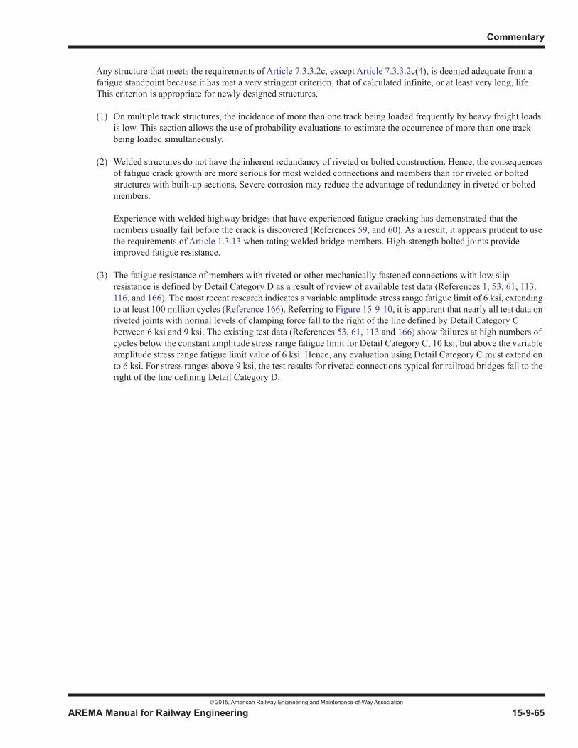
Commentary
© 2015, American Railway Engineering and Maintenance-of-Way Association
AREMA Manual for Railway Engineering 15-9-65
1
3
4
Any structure that meets the requirements of Article 7.3.3.2c, except Article 7.3.3.2c(4), is deemed adequate from a fatigue standpoint because it has met a very stringent criterion, that of calculated infinite, or at least very long, life. This criterion is appropriate for newly designed structures.
(1) On multiple track structures, the incidence of more than one track being loaded frequently by heavy freight loads is low. This section allows the use of probability evaluations to estimate the occurrence of more than one track being loaded simultaneously.
(2) Welded structures do not have the inherent redundancy of riveted or bolted construction. Hence, the consequences of fatigue crack growth are more serious for most welded connections and members than for riveted or bolted structures with built-up sections. Severe corrosion may reduce the advantage of redundancy in riveted or bolted members.
Experience with welded highway bridges that have experienced fatigue cracking has demonstrated that the members usually fail before the crack is discovered (References 59, and 60). As a result, it appears prudent to use the requirements of Article 1.3.13 when rating welded bridge members. High-strength bolted joints provide improved fatigue resistance.
(3) The fatigue resistance of members with riveted or other mechanically fastened connections with low slip resistance is defined by Detail Category D as a result of review of available test data (References 1, 53, 61, 113, 116, and 166). The most recent research indicates a variable amplitude stress range fatigue limit of 6 ksi, extending to at least 100 million cycles (Reference 166). Referring to Figure 15-9-10, it is apparent that nearly all test data on riveted joints with normal levels of clamping force fall to the right of the line defined by Detail Category C between 6 ksi and 9 ksi. The existing test data (References 53, 61, 113 and 166) show failures at high numbers of cycles below the constant amplitude stress range fatigue limit for Detail Category C, 10 ksi, but above the variable amplitude stress range fatigue limit value of 6 ksi. Hence, any evaluation using Detail Category C must extend on to 6 ksi. For stress ranges above 9 ksi, the test results for riveted connections typical for railroad bridges fall to the right of the line defining Detail Category D.
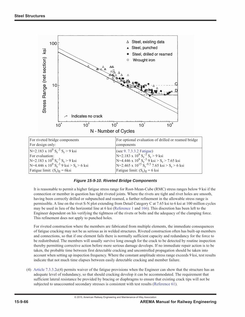
Steel Structures
© 2015, American Railway Engineering and Maintenance-of-Way Association
15-9-66 AREMA Manual for Railway Engineering
Figure 15-9-10. Riveted Bridge Components
It is reasonable to permit a higher fatigue stress range for Root-Mean-Cube (RMC) stress ranges below 9 ksi if the connection or member in question has tight riveted joints. Where the rivets are tight and rivet holes are smooth, having been correctly drilled or subpunched and reamed, a further refinement in the allowable stress range is permissible. A line on the rivet S-N plot extending from Detail Category C at 7.65 ksi to 6 ksi at 100 million cycles may be used in lieu of the horizontal line at 6 ksi (Reference 1 and 166). This discretion has been left to the Engineer dependent on his verifying the tightness of the rivets or bolts and the adequacy of the clamping force. This refinement does not apply to punched holes.
For riveted construction where the members are fabricated from multiple elements, the immediate consequences of fatigue cracking may not be as serious as in welded structures. Riveted construction often has built-up members and connections, so that if one element fails there is normally sufficient capacity and redundancy for the force to be redistributed. The members will usually survive long enough for the crack to be detected by routine inspection thereby permitting corrective action before more serious damage develops. If no immediate repair action is to be taken, the probable time between first detectable cracking and uncontrolled propagation should be taken into account when setting up inspection frequency. Where the constant amplitude stress range exceeds 9 ksi, test results indicate that not much time elapses between easily detectable cracking and member failure.
(4) Article 7.3.3.2c(4) permits waiver of the fatigue provisions when the Engineer can show that the structure has an adequate level of redundancy, so that should cracking develop it can be accommodated. The requirement that sufficient lateral resistance be provided by bracing or diaphragms to ensure that existing crack tips will not be subjected to unaccounted secondary stresses is consistent with test results (Reference 61).
For riveted bridge componentsFor design only:
For optional evaluation of drilled or reamed bridge components
N=2.183 x 10⁹ Sr-3 Sr > 9 ksi
For evaluation:N=2.183 x 10⁹ Sr
-3 Sr > 9 ksiN=4.446 x 10⁹ Sr
-3 9 ksi > Sr > 6 ksiFatigue limit: (Sr)fl = 6ksi
(see 9. 7.3.3.2 Fatigue)N=2.183 x 10⁹ Sr
-3 Sr > 9 ksiN=4.446 x 10⁹ Sr
-3 9 ksi > Sr > 7.65 ksiN=2.465 x 10¹⁵ Sr
-9.5 7.65 ksi > Sr > 6 ksiFatigue limit: (Sr)fl = 6 ksi
Commentary
© 2015, American Railway Engineering and Maintenance-of-Way Association
AREMA Manual for Railway Engineering 15-9-67
1
3
4
(5) Wrought iron riveted connections exhibit a fatigue strength represented by Detail Category D with a variable amplitude stress range fatigue limit of 6 ksi (Reference 1 and 166).
(6) For eyebars and pin plates, the critical section is at the pin hole normal to the applied load. Several studies have indicated that the stress concentration factor at such a location is in excess of 4 (Reference 53 and 142). Detail Category E is intended to provide a conservative estimate of fatigue resistance at such connections. Particular attention should be given to any forge seams or other unusual flaw-like conditions that may exist at the bore of the eyebar normal to the applied load.
Suitable analytical and/or experimental studies may show that a lower stress concentration exists if pin fit and the component geometry are favorable. If the stress concentration factor is less than 4, Detail Category D can be used to assess fatigue resistance. Detailed analysis or full size testing may be used to demonstrate that an even more favorable category is appropriate.
The inclusion of bending stresses is intended to apply primarily to hangers and similar members where pin connections may develop large bending stresses due to configuration, corrosion, wear or other causes. (Reference 30)
For advice on secondary stresses, see Article 1.3.15 and Commentary Article 9.1.3.15.
(7) Test results (Reference 61 and 113) indicate that severe corrosion may lead to the initiation of cracks. If the thickness of a component is reduced by 50% or more, the member at that location is best categorized by Detail Category E. Until more conclusive test results are available, no advice can be given in this Manual on sections with less than 50% loss of thickness.
d & e.A structure that does not pass Article 7.3.3.2c may still be adequate, but only if further evaluation demonstrates that this is the case. There are two generic ways to check this.
The first method is to ascertain as accurately as possible the actual damage done by traffic to date and to estimate the remaining life based on future projected traffic. This requires the records of the operating railroad, if they are available, and a calculation using the concepts outlined in Article 7.3.3.2d, e and f with a full spectrum rain flow analysis of actual tested trains crossing the bridge, or a short cut method using the AAR bridge fatigue charts as an approximation.
When the actual stress cycles can be estimated from known traffic, the total variable stress cycles can be estimated and the effective stress range calculated by the formula given in Article 7.3.3.2e.
The resulting coordinates can be compared with Figure 15-9-10 and Article 1.3.13 for the applicable fatigue detail.
The values of for various spans and member classifications are tabulated in Table 15-9-1. The factor i is the ratio of the number of occurrences of SRi to the total number of occurrences of cyclic stress Nv.
The second method is to refine the model of the structure by more sophisticated analytical means, or by field-testing using the structure itself as the model. In the event that calculated stress ranges give a low estimated remaining safe fatigue life, it is suggested, if economically justified, to obtain stress range data by strain gaging under traffic that is atthe upper weight range of traffic expected on the structure. In this instance, if the actual strains are less than the analytical model strains, either a rechecking of fatigue capacity using Article 7.3.3.2c or a more thorough analysis as per Article Article 7.3.3.2d, e and f will result in a longer useful calculated fatigue life.
Clearly, in the most pressing case, these methods may be combined, i.e. real traffic data and the most accurate model possible. Caution must be exercised in the application of these articles in order to avoid erroneous conclusions. For example, the use of these articles to evaluate a floorbeam or stringer without being cognizant of the effect of potential end fixity, or the application of these articles to the midsection of such a member while ignoring the real stress variation at the end connections, could lead to wrong conclusions.
Steel Structures
© 2015, American Railway Engineering and Maintenance-of-Way Association
15-9-68 AREMA Manual for Railway Engineering
When the procedures above result in a deficient remaining life estimation, several alternatives are available. Depending on the economics, consider:
Closing the structure or restricting traffic;
Repairing, strengthening or retrofitting the deficient details or replacing the structure;
Initiating frequent and very rigorous inspections, being very cognizant of fracture critical considerations;
Installing strain gages to establish actual stress ranges related to the traffic handled, to permit a more accurate analysis;
Using more sophisticated techniques, such as acoustic emission verification and fracture mechanics.
f & g.The limits and the stress ranges outlined in Article 7.3.3.2f and 7.3.3.2g on fatigue details being sufficient to eliminate the existence of the Constant Amplitude Fatigue Limit (CAFL) Stress Ranges are approximate and are based upon a small number of tests (Reference 57).
h. This paragraph draws attention to details that have low fatigue capacity with particular reference to Fracture Critical Members.
9.7.3.3.3 Allowable Stresses for Maximum Rating (2011)
a. Traditionally, bridge structures that have been designed and rated in accordance with AREA and AREMA procedures have used yielding of the net section for tension calculations. Given that there are thousands of bridges already rated based on these assumptions and with a desire that there not be a sudden change in the calculated rating of railroad bridges, the Committee felt that yielding of the net section for tension calculations may continue to be used for structures designed before 2006. This will tend to give conservative results for traditional steels. Ratings should indicate the rating criteria used (e.g. AREMA Rating 2005) so as to clarify comparisons between ratings based on different methodologies.
Nevertheless, it is imperative that steels with allowable Maximum Rating stresses based on Fy greater than 0.5 Fu be evaluated differently, particularly because some High Performance Steels (HPS) have low ultimate to yield ratios.
Applying the ultimate tensile strength to the effective and/or net section and the yield strength to the gross section in axial tension more correctly represents the behavior at failure. Because test results have been reported on the net section for some fatigue studies, the fatigue limits recommended in other articles of this Chapter may not be consistent with this provision.
Since there have been many failures in floorbeam hangers, and since an increase in allowable stress for high-strength steels in such applications is not acceptable, the allowable stress for such members has been established as that permitted for members of A36 steel, and a greater apparent factor of safety has been adopted, in line with past experience, for such members.
b. The allowable values represented in Table 15-7-1 for Shear in Rivets are intended to provide Maximum Rating parameters that cover current and historic rivet steel specifications. The current ASTM Specification for Carbon Steel Rivets is A502 Grade 1. The current ASTM Specification for Carbon Manganese Steel Rivets is A502 Grade 2. The current ASTM Specification for Weathering Steel Rivets is A502 Grade 3.

Commentary
© 2015, American Railway Engineering and Maintenance-of-Way Association
AREMA Manual for Railway Engineering 15-9-69
1
3
4
9.7.4 REPAIR, STRENGTHENING AND RETROFITTING
9.7.4.2 PLATE GIRDERS OR ROLLED BEAMS (2012)
9.7.4.2.5 Effective Span
Abutment anaylsis should include, but not be limited to, loading conditions, footing pressures, pile loads, seismic response andminimum edge distance.
9.7.5 MAINTENANCE
9.7.5.2 MAINTENANCE OF STRUCTURAL ELEMENTS (2015)
c. Ultrasonic impact treatment has been shown to alter residual stresses in welds and adjacent base metal and thereby provide improved fatigue resistance to some weld details (Reference 100, 123, 143, 151). This treatment has proven to be effective in reducing or delaying crack initiation in weld details attaching secondary members to webs of girders or beam spans.
PART 8 MISCELLANEOUS
9.8.1 TURNTABLES
9.8.1.3 BASIC ALLOWABLE STRESSES AND DEFLECTIONS (2008) R(2014)
9.8.1.3.1 Structural Components
b. The second diagram in Figure 15-8-2b. consists of two 4-axle diesel locomotives and may be used to apply this article by changing the 25 foot distance to ensure that all 8 axles are on the turntable.
9.8.2 METHOD OF SHORTENING EYEBARS TO EQUALIZE THE STRESS
9.8.2.1 GENERAL (2013)
A recommended practice for shortening eyebars to equalize their stress was originally published in the AREA Manual in 1948 following completion of a 1943 Committee 15 assignment on shortening of eyebars to equalize stress. This procedure involved heating a short length of the bar, which was restrained between clamps, to 1600 to 1800 degrees Fahrenheit, low in the range of forging temperatures, and drawing the clamps together to upset and shorten the bar. Since eyebar heads were formed by forging, these temperatures were considered appropriate. Current practice relies more on restrained thermal expansion of the heated area to produce upsetting followed by shortening as the bar cools. A detailed report comparing the effects on strength of various methods used to tighten loose eyebars and recommending the procedure for flame shortening, which was adopted as a recommended practice by the AREA in 1948, can be found in Reference 24. Fatigue tests were run on three bars in each condition. A summary of data from these tests is tabulated below. Considering the variability of test resultsand limited field experience when compared with shortening steel eyebars, extreme caution should be exercised if the method
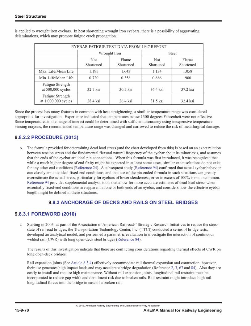
Steel Structures
© 2015, American Railway Engineering and Maintenance-of-Way Association
15-9-70 AREMA Manual for Railway Engineering
is applied to wrought iron eyebars. In heat shortening wrought iron eyebars, there is a possibility of aggravating delaminations, which may promote fatigue crack propagation.
Since the process has many features in common with heat straightening, a similiar temperature range was considered appropriate for investigation. Experience indicated that temperatures below 1300 degrees Fahrenheit were not effective. Since temperatures in the range of interest could be determined with sufficient accurancy using inexpensive temperature sensing crayons, the recommended temperature range was changed and narrowed to reduce the risk of metallurgical damage.
9.8.2.2 PROCEDURE (2013)
o. The formula provided for determining dead load stress (and the chart developed from this) is based on an exact relation between tension stress and the fundamental flexural natural frequency of the eyebar about its minor axis, and assumes that the ends of the eyebar are ideal pin connections. When this formula was first introduced, it was recognized that while a much higher degree of end fixity might be expected in at least some cases, similar exact solutions do not exist for any other end conditions (Reference 24). A subsequent study (Reference 94) confirmed that actual eyebar behavior can closely emulate ideal fixed-end conditions, and that use of the pin-ended formula in such situations can greatly overestimate the actual stress, particularly for eyebars of lower slenderness; error in excess of 100% is not uncommon. Reference 94 provides supplemental analysis tools that allow for more accurate estimates of dead load stress when essentially fixed-end conditions are apparent at one or both ends of an eyebar, and considers how the effective eyebar length might be defined in these situations.
9.8.3 ANCHORAGE OF DECKS AND RAILS ON STEEL BRIDGES
9.8.3.1 FOREWORD (2010)
a. Starting in 2003, as part of the Association of American Railroads’ Strategic Research Initiatives to reduce the stress state of railroad bridges, the Transportation Technology Center, Inc. (TTCI) conducted a series of bridge tests, developed an analytical model, and performed a parametric evaluation to investigate the interaction of continuous welded rail (CWR) with long open-deck steel bridges (Reference 84).
The results of this investigation indicate that there are conflicting considerations regarding thermal effects of CWR on long open-deck bridges.
Rail expansion joints (See Article 8.3.4) effectively accommodate rail thermal expansion and contraction; however, their use generates high impact loads and may accelerate bridge degradation (Reference 2, 3, 67 and 84). Also they are costly to install and require high maintenance. Without rail expansion joints, longitudinal rail restraint must be incorporated to reduce gap width and derailment risk due to broken rails. Rail restraint might introduce high rail longitudinal forces into the bridge in case of a broken rail.
EYEBAR FATIGUE TEST DATA FROM 1947 REPORTWrought Iron Steel
NotShortened
FlameShortened
NotShortened
FlameShortened
Max. Life/Mean Life 1.195 1.643 1.134 1.058Min. Life/Mean Life 0.720 0.358 0.866 .900
Fatigue Strengthat 500,000 cycles 32.7 ksi 30.5 ksi 36.4 ksi 37.2 ksiFatigue Strength
at 1,000,000 cycles 28.4 ksi 26.4 ksi 31.5 ksi 32.4 ksi
Commentary
© 2015, American Railway Engineering and Maintenance-of-Way Association
AREMA Manual for Railway Engineering 15-9-71
1
3
4
Longitudinal restraint also causes longitudinal forces to develop in the rail during span expansion and contraction. These forces add to the rail force developed from heating and cooling of the CWR. Additional compressive forces in hot weather might increase the risk of track buckling at bridge approaches, particularly at abutments that support expansion bearings. Additional tensile forces in cold weather might accelerate rail defect and crack growth rates and increase the derailment risk in the case of a rail break.
An alternative to rail expansion joints in CWR is to allow the rail to be unanchored on bridges under a certain length.The philosophy behind this approach is that the risk of rail break at cold temperatures, assuming there are no serious rail flaws, should be less as there is little or no transfer of forces between rail and bridge. See Article 9.8.3.3.5.2. A drawback is that, should a rail break, there may be little to constrain the resulting rail gap.
Although not specifically simulated in this investigation, damage to decks and fasteners due to large thermal displacements between rail-tie and tie-deck interfaces has been reported in the field. This will likely be more evident on riveted or bolted top surfaces or where there are other methods of holding ties longitudinally on structures where ties do not easily slide on the top surface of the span. On long riveted or similarly constrained top surfaces of spans not protected by expansion joints, fasteners should be selected that are capable of accommodating the expected rail-tie displacement without damage to ties.
Due to these fundamental conflicts, it is unlikely that all of the design goals will be completely addressed. But a balance is needed between a number of important considerations. Results emphasize the need to maintain good track lateral resistance and proper rail neutral temperature on bridge approaches to minimize track buckling potential. On approaches near expansion bearings track lateral resistance is critical. Methods to provide additional lateral resistance should be considered – for example, additional width in the ballast shoulders, full height wing walls, sheet piling and use of ties with improved lateral restraint.
The recommendations in Section 8.3 assume the following:
(1) Maximum hot weather temperature differential values for evaluation of forces due to span expansion and track buckling risk:
• A maximum rail T of 45°F above the rail neutral temperature
• A maximum span T of 45°F above the span installation temperature
(2) Cold weather values for the evaluation of rail break risk and effects as follows:
• A maximum rail T of 100°F below the rail neutral temperature
• A maximum span T of 70°F below the span installation temperature
For more extreme temperature variations that might occur in Northern regions of the US or in Canada, site specific evaluations should be carried out.
One very cold weather case was studied using the same failure criteria.
For example, with rail T of -130°F and span T of -90°F, the thermal rail force alone would be above 300,000 pounds, which is considered a rail break risk for 136 lb. rail.
Fully anchored track on riveted-top structures is likely to be at risk of rail break on all span lengths, with forces imparted into the bridge predicted to be about 120 percent of AREMA traction and braking forces for rail T of -130°F.
Controlling rail gap width of a broken rail at T of -130°F to values equivalent to those of anchored track on ballast away from bridges is highly unlikely for longer spans.
Steel Structures
© 2015, American Railway Engineering and Maintenance-of-Way Association
15-9-72 AREMA Manual for Railway Engineering
Addition of rail expansion joints would effectively eliminate any cold weather broken rail gap condition without introducing the risk of track buckling or broken rails. However, costs of installation and maintenance for rail expansion joints are high and significant bridge degradation is likely to occur due to increased impact loading for such jointsplaced on a bridge. For this cold weather case, reducing the maximum span length that may remain unanchored and without rail expansion joints to 200 feet in Article 8.3.4.2 would reduce the predicted broken rail gap to about 6 inches (almost equivalent to 5 1/2 inches on anchored track on ballast away from bridges).
Rail gaps of this magnitude are not acceptable in open track or on bridges. Most railroads perform frequent rail flaw detection in cold weather to find rails that have a high propensity for failure.
9.8.3.2 ANCHORAGE OF DECKS TO BRIDGE SPANS (2012)
9.8.3.2.1 Open Deck Bridges
a. The maximum spacing of hook bolts was changed to 4’-8” in 2010 to reflect a connection of every 4th tie assuming 10 inch wide ties and 4 inch clear distance. The previous maximum of 4’-6” assumed 9-1/2 inch wide ties.
b. Bolted fastening systems for timber ties can loosen under train traffic in a relatively short time if loosening is not prevented. Testing at FAST (Reference 45) has shown that systems employing some method to prevent loosening can significantly extend the time between maintenance. The provisions of Article 8.3.2.1(b) are based on the results of this testing. A variety of solutions are possible, some more permanent than others. Locking clips and locking nuts both allow for future adjustments. New timber ties on riveted girders will typically require a tightening after a settling period under train traffic. Solutions such as double nuts or thread fastening adhesive can make adjustments more difficult. More permanent solutions might include tack welding of nuts or mashing of bolt threads; such solutions might make adjustments impossible.
9.8.3.3 ANCHORAGE OF RAIL (2012)
9.8.3.3.5 Anchorage Requirements for Continuous Welded Rail (CWR) without Expansion Joints on Open Deck Bridges
9.8.3.3.5.1 Continuous Welded Rail without Expansion Joints on Open Deck Bridges, Rail Not Longitudinally Anchored
Some railroads deal with the conflicting problems of potential broken rails and higher forces induced in the rails and bridge byallowing the rails to be unanchored on bridges up to a certain length. The philosophy behind this approach is that the risk ofrail break at cold temperatures, assuming there are no serious rail flaws, should be less as there is little or no transfer of forcesbetween rail and bridge.
Railroads with cold weather rail flaw detection and management programs may find this to be an acceptable option. A drawback is that, should a rail break, there may be little to constrain the resulting rail gap.
9.8.3.3.5.2 Continuous Welded Rail without Expansion Joints on Open Deck Bridges, Rail Longitudinally Anchored
Testing (Reference 82, 83, 84, 115, 137) indicates that unanchored CWR might allow excessive rail gap widths should a rail break occur due to cold-induced tension. Anchoring rail as per this Article will reduce the severity of a rail gap due to a cold-induced tension break but will not reduce the gap to a level that permits train operation at the temperature ranges studied should a rail break occur.
Provisions of this Article recommend rail anchors at all ties anchored to bridge spans for spans 100 feet or less and at all tiesanchored to bridge spans only in the first 100 feet from the fixed end for longer spans. The referenced testing has indicated thateffective longitudinal resistance is dependent upon the interface between tie and structure, and the anchoring used. On spans
Commentary
© 2015, American Railway Engineering and Maintenance-of-Way Association
AREMA Manual for Railway Engineering 15-9-73
1
3
4
with a smooth interface between the tie and structure, whereas the rail fasteners may provide a strong bond between the rail and the ties, longitudinal restraint is weakest at the tie-to-structure interface. On spans with rivets or bolts protruding from the top of the bridge, the tie-to-structure interface is likely to be much stronger.
The referenced study indicated that when every 2nd tie is box-anchored on track on subgrade away from the bridge, and either:
• every 2nd tie is box-anchored on spans with protruding rivets or similar tie-to-structure interface, or
• every tie is box-anchored on spans with smooth tie-to-structure interface
an equivalent unacceptable rail gap from a broken rail results under the following three conditions:
• 300 foot long bridges under the cold scenario (rail T = 100° F)
• 200 foot long bridges under the extreme cold scenario (rail T = 130° F)
• up to 500 foot long bridges in climates that are warmer (rail T = 70° F).
To meet the requirements of this article, rail anchors are placed at the same locations as the anchors between the tie and the structure at every 4th tie (maximum spacing of 4’-8”) with riveted or similar tie-to-structure interface, or at a reduced spacingon smooth interfaces. This is equivalent to anchoring at half the anchorage typically used on track on subgrade. To evaluate reduced longitudinal restraint rail-to-tie fasteners, half the anchorage used on track on subgrade is approximately 40 lb/in/railon the bridge.
Unless overriding circumstances exist, anchoring more ties than recommended should also generally be avoided on riveted or bolted tops or other methods of holding ties longitudinally on spans, as it might increase the risk of either hot-weather-inducedbuckling on bridge approaches, or cold weather breaks.
9.8.3.4 RAIL EXPANSION JOINTS (2012)
While use of rail expansion joints introduces increased cost and bridge degradation, their use can effectively control the risk of bridge approach track buckling, excessive rail gap widths from cold weather rail breaks, and high forces due to relative displacement between bridge and track.
Results of factorial testing carried out under very cold temperatures to determine actual span/rail behavior with various bearingconditions have not been reported. Theory and extrapolation from testing at smaller temperature ranges seem to indicate a need for rail expansion joints as mentioned above.
There are anecdotal instances of problems where expansion rails were not placed on:
• long bridges with relatively short spans,
• spans over 300 feet with provision for floor system expansion (Article 1.2.13) and
• bridges resulting in damage to deck timbers from standard rail anchors.
But, there is also anecdotal evidence that it is possible to eliminate rail expansion joints on some long spans without seriousconsequences.
There are several possible explanations for this:
• It is possible that the bridge and rail neutral temperatures adjust somewhat with changes of season to reduce the potential severity of the broken rail gaps and the associated forces.
Steel Structures
© 2015, American Railway Engineering and Maintenance-of-Way Association
15-9-74 AREMA Manual for Railway Engineering
• Rails may have the capacity to resist forces considerably greater than the 300,000 pounds considered a rail break risk for 136 lb rail. Any weaknesses in rail need to be identified through more frequent rail flaw inspections, especially during cold weather periods.
• There is a difference in behavior between tie-to-structure interfaces that are smooth and those that have more resistance to sliding (e.g: protruding rivet heads or ties held in place by angles, etc.).
• Use of zero longitudinal restraint rail clips eliminates most of the transfer of longitudinal forces between rail and bridge structure.
• There is also a difference in behavior in cases where bearings from adjacent spans are placed to allow for opposing movement (e.g.: two expansion bearings on the same pier) and those where the bearings do not allow opposing movement.
• Non-functioning bearings may play a significant role.
• Stress in the bridge structure may be higher than expected, but the structure may still be able to accommodate this condition without noticeable signs of deformation.
Further research is needed to fully explain the conflicting issues.
9.8.3.4.4 Number and Positioning of Rail Expansion Joints on Bridges with Continuous Welded Rail
b. In order to ensure the stability of the backwall while establishing the distance of the rail expansion joint behind the abutment, consideration must be given to the following parameters:
• Significant dynamic and impact factors
• Transition in subgrade stiffness
• Lack of mechanized maintenance
• Low bridge approaches
• Poor drainage
f. Expansion length of rail is limited to 1500 feet in this Manual, which is based on:
• Strength
• Tolerable Rail rupture gap
• Differential displacement between bridge and rail
• Rail stability (Buckling)
9.8.4 UNLOADING PITS
9.8.4.1 SCOPE AND PURPOSE (2015)
The original section on unloading pits was incorporated into the Manual in 1993, before the implementation of the Alternate Live Load. In the 2013 edition, superstructure was upgraded to accommodate the Alternate Live Load. Following recommended industry practices, the criteria for using an inverted rail as a supporting beam were removed and the designer

Commentary
© 2015, American Railway Engineering and Maintenance-of-Way Association
AREMA Manual for Railway Engineering 15-9-75
1
3
4
directed to use the structural support beams of Figure 15-8-6. The proposed rail sections of the table in the independent unsupported rail section correlate with the running rail sections of Chapter 4, Part 1. The recommended unloading pit maximum span was shortened to conform with FRA track tie spacing requirements. The welded diaphragm connection to the main supporting beams of Figure 15-8-6 was revised to a bolted diaphragm connection to improve the fatigue category and extend service life while allowing for a reduced beam section.
9.8.4.6 STRUCTURAL SUPPORTING BEAMS (2015)
In the 2013 edition, service load design method was used to analyze supporting beams of ASTM A36 structural steel for both bending and shear, applying the Alternate Live Loading at a maximum speed of 10 mph with the associated live load impact of 28%. The beams in the table in Figure 15-8-6 were resized and the number of beam choices was optimized to better reflect available choices. A double-angle bolted connection detail was selected for the diaphragms which essentially eliminated any fatigue concerns and allowed for the use of a reduced section.
9.8.4.7 CONCRETE PIT (2015)
Concrete design and detailing were removed from Chapter 15 as they had become obsolete. The designer is directed to Chapter 8.
9.8.5 WALKWAYS, HANDRAILS, AND FIXED LADDERS ON BRIDGES
9.8.5.2 CLEARANCES AND MINIMUM DIMENSIONS (2014)
9.8.5.2.3 Fixed Ladders
b. Regulations for fixed ladders in the USA for General Industry are contained in OSHA 29 CFR 1910.27, “Fixed Ladders.” Federal regulations in the USA for fall protection systems refer to FRA Bridge Worker Safety Standards, 49 CFR 214, Subpart B. Regulations for fixed ladders in Canada are contained in the Canada Labour Code Part II, Sections 2.6 to 2.8 “Fixed Ladders.” Federal regulations in Canada for fall protection systems refer to the Canada Labour Code Part II, Section 12.10. Some railroads may also be subject to additional State or Provincial regulations.
9.8.5.3 LOADS (2014)
9.8.5.3.3 Fixed Ladders
The 300 lb load is to ensure that workers carrying tools and equipment may be accommodated.
9.8.7 GUIDE TO THE PREPARATION OF A SPECIFICATION FOR THE CLEANING AND COATING OF EXISTING STEEL RAILWAY BRIDGES
9.8.7.4 COATING SYSTEMS (2009)
9.8.7.4.1 General
b. The ratio of pigment to vehicle of a coating determines the level of coating gloss, the ease of application and other properties. Coatings are most often referred to by the resin with which they are formulated. Examples of these are alkyd, epoxy and urethane.
These various resins react in different ways to develop the dry coating film; for example, oxidation, solvent evaporation or chemical reaction of multiple components called polymerization. These curing mechanisms, as well as the other common coating characteristics, are discussed in the following sections.
Steel Structures
© 2015, American Railway Engineering and Maintenance-of-Way Association
15-9-76 AREMA Manual for Railway Engineering
Coatings for anti-corrosion service are segregated into three distinct types: barrier coatings, inhibitive primers and sacrificial galvanic protection providers. The barrier coatings offer protection by film forming and creating a barrier to minimize ion migration and to some extent moisture penetration to the steel substrate. Inhibitive primers reduce electro-chemical corrosive action at the steel substrate by using sacrificial inhibitive pigmentation in the coating which is effective in passivating the steel surface and deterring corrosion formation. Galvanic protection prevents corrosion by using a material of lower electro-chemical potential such as metallic zinc or aluminum pigmentation which sacrifices itself to protect the steel. This occurs in addition to the film’s barrier protection properties. Galvanic protective coatings, specifically zinc-rich coatings, offer the highest levels of protection to properly prepared steel substrate and are resistant to problematic undercutting corrosion. It should be noted that galvanizing can cause hydrogen embrittlement. This is usually not a problem with very heavy, thick, low strength steel members.
c. Different generic coating types are often used in conjunction with each other as “systems” to provide maximum levels of protection. However, due to the coating composition, some are not compatible with others. Therefore, development of this “blend” of different coating types is critical to the long-term performance of the system. By using a systematic approach to building a coating film, coatings that offer benefits as primers may be coupled with coatings that offer other desirable characteristics such as moisture, chemical and ultraviolet resistance, plus color/gloss retention, etc. Manufacturers also formulate coatings with different vehicles or pigment combinations, along with other complex chemical modifications to maximize the protective qualities.
9.8.7.4.2 Coating Selection
Primary consideration must be given to the service environment which the coating system must endure. Railway bridge structures are often found in mild exposure environments; however, chemicals used in conjunction with snow and ice removal, the proximity of structures to industrial plants or factories, and even overspray of agricultural chemicals can dramatically affect the coating system’s performance. Coating systems for railroad bridges over roadways must also resist abrasion from splash and stones thrown against coated surfaces by moving traffic and must also have the chemistry within the system to mitigate the crevice corrosion and pack rust which is usually present on these structures. Certain coating formulations may be successfully applied with lesser degrees of surface preparation, while others require very clean surfaces. This is a factor whichmust be given careful attention when choosing a coating system. When cleaning steel on an existing structure where total removal is required, abrasive blast cleaning to an SSPC-SP5 “White Metal Blast Cleaning”, SSPC-SP10 “Near-White Metal Blast Cleaning” or SSPC-SP6 “Commercial Blast Cleaning” are the preferred methods of surface preparation. SP5 and SP10 cleaning standards may be difficult to achieve on existing structures under field conditions, especially for open deck structures,intricate trusses and open box sections. Another consideration in selection of a coating system is the ability of the topcoat toaccept additional surface preparation and touch-up or overcoating. Many topcoats cure to form smooth, dense and hard films. Hard, abrasion-resistant coatings, such as two-component urethanes, may require more rigorous surface preparation, such as abrasive blast cleaning, to superficially roughen the surface and promote adhesion of subsequently applied coatings. On the other hand, softer film topcoats, like alkyds or acrylics, often accept additional maintenance coats of paint with minimal surface preparation (such as simple solvent cleaning or high pressure water washing).
The materials and methods used to clean and coat steel bridge structures are constantly changing. The following items, as a minimum, should be considered for all coating specifications:
• Life expectancy and life cycle costs
• Successful protection of the structure and its critical elements (joints, connections, bearings, etc.)
• Compatibility with existing systems (where applicable)
• Ease of application and availability of materials
• Environmental conditions
• Aesthetics
Commentary
© 2015, American Railway Engineering and Maintenance-of-Way Association
AREMA Manual for Railway Engineering 15-9-77
1
3
4
• Overall coating strategy
9.8.7.4.3 Materials/Systems
a. Penetrants for treating crevice corrosion and pack rusted joints that cannot be cleaned are as follows:
(1) Epoxy Penetrating Sealers – Epoxy penetrating sealers are low molecular weight epoxies based on Chelated Polymeric Oxirane technology. These high performance, two-component chemically-cured high solids epoxy penetrating sealers are recommended for rusty steel when environmental, economic or safety concerns restrict abrasive blast cleaning. The extraordinary penetrating properties of these sealers provide a means of reinforcing rusty steel substrates, insuring adhesion of subsequent coatings. They are equally effective at penetrating, reinforcing and sealing concrete and masonry surfaces in all industrial environments. They improve the effectiveness and efficiency of the maintenance coating process by penetrating and sealing crevices, joints, back-to-back angles and edges of old coatings, improving the service life of the maintenance coating system. These sealers also serve to seal aged “White-Rusted” zinc galvanized surfaces for recoating. Epoxy penetrating sealers are two-component products that cure by crosslink polymerization. These coatings provide excellent adhesion to marginally prepared steel (SP2 minimum) and old coatings. Their lower viscosities allow epoxy sealers to penetrate rust and wick into surface voids and around rivet heads. In addition, this wicking action penetrates discontinuities in existing coatings which often times seals these areas and reduces undercutting and peeling. The low viscosity also allows epoxy sealers to be applied by many techniques. This includes conventional air and airless spray, brush and roller, flood or flow coating methods, and by low pressure hand pump sprayers (similar to those used to spray concrete curing compounds, form release oils, or garden chemicals). Epoxy penetrating sealers usually possess very high volume solids content typically over 80%, develop lower contractive curing stresses, and meet the most stringent VOC regulations (often zero VOC). Corrosion inhibitors are generally used in their formulations. Since epoxy penetrating sealers provide low film build (1-2 mils), the total amount of curing stress and physical coating weight that the existing coatings must bear is also reduced. The drawbacks of these coatings are that they require multiple component mixing, have short pot lives, cure hard and may crack on flexible structures, must be topcoated to achieve maximum resistance, have high material cost, do not stay active if applied to crevice corroded or pack rusted joints and connections, have critical recoat times, and have application temperature limitations. The sealers are usually used as primers to bind up surfaces to be overcoated and are then topcoated with alkyd, acrylic, epoxy, or urethane coatings.
(2) Moisture Cured Urethane Penetrating Sealers – These penetrants are thin and designed to flow into the joints and connections binding them up and sealing them up. For additional information see b(4).
(3) High Ratio Co-Polymerized Calcium Sulfonate Penetrant Sealers – These penetrants are active non drying chemical treatments for crevice corroded and pack rusted joints and connections designed to stop corrosion by neutralizing acid, displacing moisture and scavenging oxygen. For more information see b(8).
b. Coatings for recoating prepared steel are as follows:
The premier coatings for blast cleaned steel have historically been 3 coat zinc epoxy urethane systems (which require this type of surface to perform properly). However, this does not mean that these coatings are the answer in all situations, as they have limitations as well. The following describes the various coating types which are available, gives a brief history of their development and usage, addresses surface preparation requirements, discusses touch-up capabilities, reviews costs, and in some cases provides an estimate of the service life given the assumed exposure conditions.
(1) Alkyds – Alkyds are a type of synthetic resin that cures by air oxidation. They are basically formed by a reaction among an acid, an alcohol, and oil. Alkyds are formed and classified by the amount and type of oil present within the formulation. “Long oils” contain greater quantities of oil and take longer to dry, while “short oils” have less oil and shorter dry times. Medium length oil-alkyds are a good compromise of the two and are consequently the most versatile and widely used. With the reduction in the amount of natural oil and an increase in the synthetic alkyd

Steel Structures
© 2015, American Railway Engineering and Maintenance-of-Way Association
15-9-78 AREMA Manual for Railway Engineering
resin, the resistive properties of the alkyds are superior to those of natural oils. The use of synthetic resin translates into improved resistance to water, but has little or no effect on the resistance to chemicals and solvents.
Because of the presence of the oil in the alkyd, which aids in surface wetting, surface preparation requirements are minimal. Therefore, the removal of all loose materials by hand or power tools is usually adequate for the use in mild to moderate exposures. However, abrasive blast cleaning or water jetting to the same cleaning standard (i.e. SSPC-SP6 or SSPC-SP12-WJ3) still provides superior surface cleanliness and may increase long-term coating system performance. In most cases the high cost of such surface preparation would indicate the use of higher performance coatings which would increase long term performance. Touch-up may be performed with a similar material, or an oil-based coating if necessary. They can be easily applied by maintenance personnel.
(2) Modified Alkyds – The versatility of alkyds is further enhanced by combining them with any number of natural and synthetic resins. By modifying the basic alkyd, additional corrosion protection may be gained while the ease of application and surface tolerance is maintained. While the basic alkyd resins have been modified by combining them with other materials, the modified product does not develop all of the characteristics of these materials. They offer increased performance to the oil-based resins alone, but do not match the performance of the more advanced coatings. These materials offer a potential solution for mild to moderate environments where additional protection is necessary, but a cost-effective coating is desired. While there are many types of modified alkyds that have been developed for specific uses, this discussion will include only three that have significance to steel from which all coatings have been removed: vinyl alkyds, calcium sulfonate modified alkyds and silicone alkyds.
(a) Vinyl Alkyds – The Vinyl Alkyds offer decreased drying times, better adhesion and water resistance, and improved exterior durability compared to the basic alkyd formulation. Because of the vinyl modification, some formulations are also capable of being topcoated with high performance, stronger-solvent topcoats such as epoxy or urethane. Vinyl alkyd modifications are generally used in readily recognized products referred to as “universal metal primers”.
(b) Silicone Alkyds – Similar to the vinyl alkyd, the silicone alkyds as compared to unmodified alkyds offer an increase in corrosion protection. The silicones also offer the capability of resisting somewhat higher temperatures while also improving gloss retention, color retention, and abrasion resistance. The increase in resistance qualities appears to be directly related to the quantity of silicone used in the modification. As such, the amount of silicone should be selected and specified. A 30% silicone content is a minimum amount of silicone commonly specified to ensure superior performance.
(c) Calcium Sulfonate Modified Alkyds – similar to the silicone modified alkyd in that a small percentage of calcium sulfonate is used to enhance the properties of the base alkyd resin. The calcium sulfonate is added to the formula to give the alkyd better corrosion resistance, wetting properties, thixotroscopy (ability to resist runs or sags) and as a pigment suspension agent. The amount of calcium sulfonate in modified alkyds may range from 2 to 15 percent by weight with an improvement in performance with increasing calcium sulfonate content. For best performance a percentage by weight of 14% to 15 % is recommended. It is also important to insure that the ratio of calcium carbonate to active sulfonate is approximately 10 to 1. This ratio is required for a balanced formula and is the ratio that has been used in the field proven materials. To reduce costs some suppliers may supply what they call a calcium sulfonate alkyd but the formula is basically low cost, low quality calcium carbonate filler with only a small percentage of active sulfonate added. Specifications should clearly define the percentage of active sulfonate and quality control procedures should be put in place to enforce the specification.
(3) Zinc-Rich Coatings – Zinc-rich coatings provide a high level of protection for blast cleaned steel, but are expensive relative to other coatings. Zinc-rich coatings provide a combination of barrier and galvanic protection.
Zinc dust dispersed through various resins provides the galvanic and barrier protection as well as improved abrasion resistance. Zinc-rich coatings offer significantly better performance than other types, through galvanic action described earlier. This protection greatly reduces sub-film corrosion and cancerous undercutting corrosion. Their limitations include somewhat higher cost, reliance on a high degree of surface preparation, skilled
Commentary
© 2015, American Railway Engineering and Maintenance-of-Way Association
AREMA Manual for Railway Engineering 15-9-79
1
3
4
applicators, and careful selection of intermediate and/or topcoats. Zinc-rich primers require the surface to be free of flash rust for good performance. The industry standard is for surface temperature to be several degrees above the dew point for zinc primer application. Zinc-rich coatings used alone also offer reliable one-coat protection in normal weather conditions.
Zinc-rich coatings are available in organic and inorganic formulations. Inorganics are considered to provide superior protection, but they are more sensitive to the surface preparation and applicator skills. Inorganic zinc-rich coatings require surface preparation to Near-White Metal (SSPC-SP10) at a minimum, with White Metal (SSPC-SP5) preferred. Field touch-up is performed with an organic material, such as a surface-tolerant epoxy, primarily because inorganic zinc-rich coatings require spray application and are less user friendly. They can be used very effectively in maintenance applications, but should be substituted with organic zinc on complex surfaces, e.g. steel lacing, corroded crevices, pack rusted joints and connections. Inorganic zinc primers may be used in one, two or three-coat systems. Usually, epoxies are used as intermediate coats and acrylic aliphatic urethanes as finish coats; however, waterborne acrylic coatings have also been successfully used as topcoats for zinc-rich coatings. Inorganic zinc or galvanizing are the preferred shop primers for replacement steel used to repair existing structures. Care must be taken to ensure that all shop and field coatings specified are compatible.
Organic zinc coatings can be made from many different generic coating types, but the most prominent are epoxy and moisture-cured urethanes. Epoxy zinc-rich coatings have primarily the same characteristics as epoxies; excellent adhesion, abrasion resistance, good water resistance, and if modified increased flexibility. The zinc dust dispersed in the coating gives galvanic (sacrificial) protection against corrosion and improves abrasion resistance. Moisture-cured organic zinc-rich primers have the advantage of galvanic protection coupled with good adhesion, abrasion resistance, and sunlight resistance when topcoated with a moisture-cured aliphatic topcoat. In addition moisture-cured urethane organic zinc-rich primers have the ability to be applied in high humidity and colder temperatures. Field application must be monitored carefully as too much moisture will cause carbon dioxide gassing or poor adhesion. Coating manufacturers often tout the ability of their moisture-cured primer to adhere to damp steel. Organic zinc coatings are generally topcoated with epoxies, acrylic urethanes, 100% acrylics, or moisture-cured urethanes.
(4) Moisture-Cured Urethanes – Moisture-cured urethane coatings react with atmospheric moisture (humidity) which initiates the cure, creates carbon dioxide gas and provides a protective coating film. These single-component products have excellent performance characteristics, including abrasion resistance, durability, and appearance. Zinc-rich primer formulations made from moisture-cured resins give excellent protection against corrosion of steel. Many moisture-cured urethane intermediate and finish coat formulations use micaceous iron oxide to provide corrosion resistance. Moisture-cured urethane coatings are ideal for field application, since they may be applied in periods of high humidity and moderate cold temperatures. Moisture-cured urethane coatings have several unique disadvantages. They are moisture sensitive in the container, which can lead to gelling. If too much moisture is present they will produce excessive carbon dioxide gas that could damage the film. When properly cured they provide a hard and smooth coating film that may be difficult to overcoat in the future. Recoat windows, the time during which an additional coat can be applied without additional surface preparation such as sanding or light abrasive blasting, are narrow. They are more costly to purchase than other high-performance coatings but may be more cost effective if conditions for application are right. Moisture-cured urethanes have only fair flexibility, limited resistance to acid and chemicals, and notable yellowing when exposed to the ultraviolet rays of sunlight. Moisture-cured urethanes require careful control of application thickness, particularly in windy, humid conditions.
(5) Epoxy Coatings – Epoxy coatings have excellent adhesion to steel, excellent abrasion resistance, good water resistance, and when modified relatively good flexibility. For bridge coatings, epoxy resins are used primarily for zinc-rich primers, and for intermediate coats over inorganic or organic zinc-rich primers. Since epoxies are two-component materials, they must be mixed in proper proportions to cure correctly. Other disadvantages of epoxy coatings are that most materials have limited pot lives, specific recoat time intervals, and application temperature and humidity restrictions. Epoxies are not usually used as finish coats because UV light attacks the structure and they break down causing chalking.

Steel Structures
© 2015, American Railway Engineering and Maintenance-of-Way Association
15-9-80 AREMA Manual for Railway Engineering
(6) Epoxy Mastic Coatings – Epoxy mastic coatings cure by chemical reaction when a hardener is added to the resin. Since the percentage of solids by volume is higher than that of regular epoxies, the amount of solvent used in the coating formulation is low. Therefore, most epoxy mastics are VOC compliant and are less likely to overly soften, wrinkle, or lift old coatings. They also may offer a higher film build per coat, which serves to improve on already good abrasion and environmental resistance. Additionally, many formulas have low temperature catalysts or additives which may extend the coating season into periods of cooler weather. Epoxy mastic coatings also readily lend themselves to modifications which enhance their corrosion resistance and film strength. One such modification is the addition of leafing or non-leafing aluminum into the coating, which serves to lower the epoxy resin’s susceptibility to degradation by ultraviolet light and decreases moisture permeability of the film. For new construction or exposed surfaces, aluminum flake pigmented epoxy mastic systems are the industry standard when epoxy mastics are used. This addition increases the corrosion protection of the system and the mechanical strength of the coating film.
Disadvantages of epoxy mastics are their higher cost and the epoxy resins’ inherent degradation by ultraviolet light. Sunlight and weathering exposure commonly result in chalking and/or color fading of the exposed film. As a result, if chalking and discoloration cannot be tolerated, they must be topcoated with better gloss and color retentive finish coats, such as polyurethanes or acrylics. However, it is important to note that any chalking which takes place has been found to have little or no effect on coating performance other than life expectancy due to the film eroding away. Other disadvantages include slower drying time and strong odors. Other limitations of epoxy mastics are that many have limited recoat times and multiple components which require mixing, include toxic solvents and have limited pot life. These coatings are toxic and require special handling in the field.
A large variety of epoxy mastic formulations exist, with dramatic differences in performance between the best and the worst. Proper specification is needed to achieve the desired results from this coating.
(7) Waterborne Acrylic Coatings – Waterborne acrylics are single-component coatings which cure by coalescence of the resin particles that are dispersed in water. Variations of waterborne acrylics are used in both protective and architectural coatings in the form of primers, intermediate coats, and finish coats. These materials have higher moisture vapor transmission rates which allow moisture to readily pass through the coating film. Therefore, in coatings for use on steel, anti-corrosive pigments are added to inhibit rust formation. Acrylics offer excellent exterior durability along with gloss and color retention similar to that achieved by urethane coatings. Waterborne acrylics also have excellent flexibility, good drying times under low humidity conditions, relatively low odor, are easy to apply, and readily accept future overcoats. Lower abrasion resistance properties, along with relatively higher costs, are some of the disadvantages of waterborne acrylic coating materials. Limitations of acrylic coatings are their fair corrosion resistance, application temperature limitations above 50°F, and relatively poor chemical resistance compared to a two-component high performance coating system such as an epoxy. Waterborne acrylic coatings are not resistant to high levels of moisture or prolonged condensation.
(8) High Ratio Co-Polymerized Calcium Sulfonates – High Ratio Co-Polymerized Calcium Sulfonate coatings are different from Calcium Sulfonate Modified Alkyds. High Ratio Co-Polymerized Calcium Sulfonates are made up of a co-polymerized reacted synthetic resin with a unique patented crystalline modification that cures by air oxidation. These coatings provide protection by a combination of chemical and physical properties. The coatings are excellent chemical treatments and film formers, and in both field and laboratory tests have demonstrated that they are at the top of the performance envelope, when compared to traditional multi-coat high performance coatings. The High Ratio Co-Polymerized Calcium Sulfonate coatings' major advantage is the active Penetrant/Sealer and Primer/Topcoat, which have a fifteen-year history on structures in the field, and that stop the progression of crevice corrosion and pack rust specifically in joints and connections. This activity, in the joints and connections, is unique to the High Ratio Co-Polymerized Calcium Sulfonate chemistry and supplies the engineer with a valuable tool for the preservation of aging complex structures, where crevice corrosion and pack rust are present. In addition the coatings are very environmentally friendly with the system having a LC50 at 96 Hrs fish kill at 41007 ppm (note typical epoxies and urethanes are 2-4 ppm). This test is used to assess the toxicity of coatings if they are introduced into the fish habitat. The performance of the High Ratio Co-Polymerized Calcium Sulfonate coatings is related directly to the percentage amount of synthetic crystalline based material and of active sulfonate in the formulation. The ratio should be a minimum 90 to maximum 105 TBN (Total Base Number) and a
Commentary
© 2015, American Railway Engineering and Maintenance-of-Way Association
AREMA Manual for Railway Engineering 15-9-81
1
3
4
minimum 9.5 to 11% active sulfonate. There must be a minimum 9 to a maximum 11 to 1 ratio total base number to active sulfonate. Calcium sulfonate coatings with lower active numbers will not perform as well and are not equal to the High Ratio Co-Polymerized Calcium sulfonate type products, and should not be included in the same specification. The formulation should contain no fillers or extenders. Some manufacturers fill their coatings with low cost calcium carbonate fillers to lower the price with a negative impact on long term performance. Unlike calcium sulfonate alkyds the alkyd or co-polymer used in conjunction with the High Ratio Co-Polymerized Calcium Sulfonate should not comprise more than 25 to 27 % of the formulation. Formulations with more than 27% alkyd or co-polymer would not be considered equal to the High Ratio Co-Polymerized Calcium Sulfonate formulations which have set the high performance standard since 1991. Increasing the amount of alkyd or co-polymer is a way to reduce the cost, with the net effect of reducing the long term performance.
(9) Galvanizing – Hot-dip galvanized steel has been effectively used for more than 150 years. The value of hot-dip galvanizing stems from the relative corrosion resistance of zinc, which, under most service conditions, is considerably better than iron and steel. In addition to forming a physical barrier against corrosion, zinc, applied as a hot-dip galvanized coating, cathodically protects exposed steel. Furthermore, galvanizing for protection of iron and steel is favored because of its low cost, the ease of application, and the extended maintenance-free service that it provides. Though the process may vary slightly from plant to plant, the fundamental steps in the galvanizing process are:
Soil and grease removal – A hot alkaline solution removes dirt, oil, grease, shop oil, and soluble markings.
Pickling – Dilute solutions of either hydrochloric or sulfuric acid remove surface rust and mill scale to provide a chemically clean metallic surface.
Fluxing – Steel is immersed in liquid flux (usually a zinc ammonium chloride solution) to remove oxides and to prevent oxidation prior to dipping into the molten zinc bath. In the dry galvanizing process, the item is separately dipped in a liquid flux bath, removed, allowed to dry, and then galvanized. In the wet galvanizing process, the flux floats atop the molten zinc and the item passes through the flux immediately prior to galvanizing.
Galvanizing – The article is immersed in a bath of molten zinc at between 815º-850º F (435º-455º C). During galvanizing, the zinc metallurgically bonds to the steel, creating a series of highly abrasion-resistant zinc-iron alloy layers, commonly topped by a layer of impact-resistant pure zinc.
Finishing – After the steel is withdrawn from the galvanizing bath, excess zinc is removed by draining, vibrating or for small items - centrifuging. The galvanized item is then air-cooled or quenched in liquid. Galvanized steel that is to be topcoated for cosmetic considerations must be air-cooled without quenching to avoid adherence problems.
Inspection – Coating-thickness and surface-condition inspections complete the process.
(10) Metalizing – Metalizing is a thermal spray process that requires surface preparation by abrasive blasting followed by metal spraying which can then be sealed and thereafter topcoated. There is a higher initial cost for metalizing but new application technologies and life cycle costing show that it is about half the cost of coating with high performance three coat systems. The three spray wires used for atmospheric or immersion service are pure aluminum, pure zinc or an 85/15 alloy of these two metals. (The alloy is approximately 85% zinc and 15% aluminum by weight.) A metalized coating may be bare sprayed metal, sprayed-metal-plus-sealer or sprayed-metal-plus-sealer-plus-topcoat. Coating thickness may vary according to application from .004" to thicker coats of zinc in the range of .012" - .014" for seawater splash zones. Metalizing is considered a cold process in that the aluminum or zinc is deposited onto steel by spraying rather than by dipping the steel into a bath of molten zinc as with galvanizing. The steel remains relatively cool at about 250º-300ºF. There is virtually no risk of heat distortion or weld damage by metalizing. There are no VOC's (volatile organic compounds) in the metalized coating. There is no cure time or temperature limit for metalizing, so metalizing may be applied throughout the year. The sealed-sprayed-metallic coating is often the most economical and is the preferred system of the three metalized coating options as it offers the longest service life. The use of a coating directly over an unsealed sprayed-metal coating
Steel Structures
© 2015, American Railway Engineering and Maintenance-of-Way Association
15-9-82 AREMA Manual for Railway Engineering
should be avoided. The disadvantage to the system is that the blast profile is very specific. The profile must be a minimum of 4 to 4.5 mils and angular in nature. Careful inspection is required to insure it is achieved.
(11) Polyurea Coatings – Polyurea-based thick film coatings encompass a diverse group of products. A pure polyurea is the combination of isocyanates with a long chain amine, excluding the hydroxyl reactive sites. For reference, pure polyurethane coatings are formulated using an isocyanate combined with hydroxyl-containing polyols. Polyurea coatings can be formulated as hybrids by combining isocyanates with a mixture of polyols and long chain amines, resulting in a coating that bears the performance characteristics of a polyurethane and a polyurea coating. Polyurea coatings can be either aromatic or aliphatic, and can be formulated with catalysts, pigments, fillers and other performance-enhancing additives. Pure polyurea coatings offer the highest degree of chemical resistance, but hybrids offer improved wetting (the cure time is retarded) and other desirable performance characteristics. The relative production cost is lowest for a polyurethane, increases for polyurea hybrids, and is the highest for pure polyurea coatings. These new technology polyurea coatings and their hybrids offer the industry an environmentally compliant, high performance option (with very attractive film forming properties) for corrosion prevention and asset protection. However, like all industrial protective coatings they have performance limitations and minimum surface preparation requirements. Use of these materials outside of the recommended service environments or over marginally prepared surfaces can result in catastrophic failure and costly rework.
c. Coatings for Overcoating Existing Coatings and Stable Substrates
Many coating types are reformulated specifically for use as overcoating materials. At a minimum, the following generic coating types would usually be recommended for over coating the existing coatings on railway structures. Compatibility testing should be done between the coating to be overcoated and the coating to be applied to insure it will not delaminate or otherwise adversely affect the adhesion properties of the existing coating.
(1) Alkyds – See b(1).
(2) Modified Alkyds – See b(2).
(3) Epoxy Mastic Coatings – Epoxy mastic coatings offer many advantages as overcoats and are widely specified for use as an overcoating material. Because epoxy mastics are formulated to have good wetting properties, they possess excellent adhesion to marginally prepared contaminant free surfaces (SSPC-SP2 minimum). Testing should always be done to insure compatibility with the existing coating. When properly formulated, the coatings will maintain very low stress, making them good overcoat candidates for aged alkyds. For additional information see b(6).
(4) Moisture-Cured Urethane Coatings – See b(4)
(5) Low Molecular Weight Epoxy Penetrants – See a(1)
(6) Waterborne Acrylic Coatings – Waterborne Acrylic Coatings are good overcoating materials because they have lower shrinkage stresses as they cure and therefore apply little contractive stress on existing coatings. Since these coatings use water as a solvent, they are VOC compliant and do not over-soften or lift existing films. They are typically used in overcoating as finish coats over epoxy mastics or epoxy penetrant sealers. For additional information refer to b(7)
(7) High Ratio Co-Polymerized Calcium Sulfonates – See b(8)
(8) Urethane Systems – Chemically cured acrylic urethane coatings are not typically used as overcoating primers, but do offer excellent characteristics as finish coats with superior gloss and color retention, and UV resistance over some of the materials previously discussed (Zinc primers, epoxy mid coats, epoxy mastics, epoxy penetrating sealers, and moisture cured urethanes). These coatings offer excellent water and corrosion resistance. They also allow lower application temperatures, and can be modified to be high solids, high build, or 100% solids coatings, thus VOC compliant. Disadvantages with urethane coatings are that they have limited flexibility and are two-
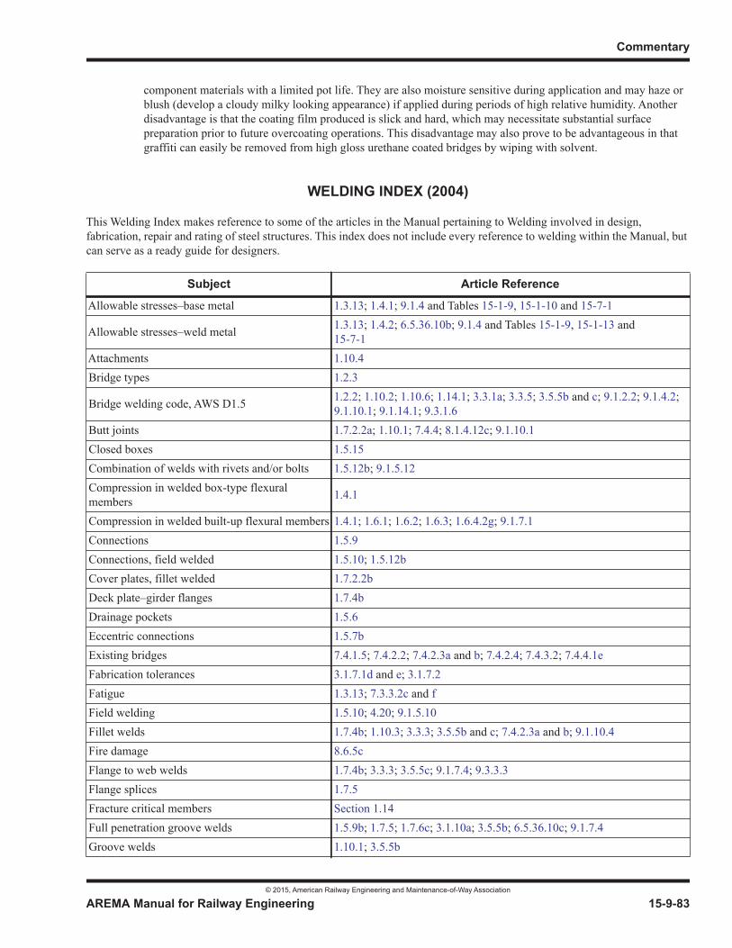
Commentary
© 2015, American Railway Engineering and Maintenance-of-Way Association
AREMA Manual for Railway Engineering 15-9-83
1
3
4
component materials with a limited pot life. They are also moisture sensitive during application and may haze or blush (develop a cloudy milky looking appearance) if applied during periods of high relative humidity. Another disadvantage is that the coating film produced is slick and hard, which may necessitate substantial surface preparation prior to future overcoating operations. This disadvantage may also prove to be advantageous in that graffiti can easily be removed from high gloss urethane coated bridges by wiping with solvent.
WELDING INDEX (2004)
This Welding Index makes reference to some of the articles in the Manual pertaining to Welding involved in design, fabrication, repair and rating of steel structures. This index does not include every reference to welding within the Manual, butcan serve as a ready guide for designers.
Subject Article Reference
Allowable stresses–base metal 1.3.13; 1.4.1; 9.1.4 and Tables 15-1-9, 15-1-10 and 15-7-1
Allowable stresses–weld metal 1.3.13; 1.4.2; 6.5.36.10b; 9.1.4 and Tables 15-1-9, 15-1-13 and15-7-1
Attachments 1.10.4Bridge types 1.2.3
Bridge welding code, AWS D1.5 1.2.2; 1.10.2; 1.10.6; 1.14.1; 3.3.1a; 3.3.5; 3.5.5b and c; 9.1.2.2; 9.1.4.2;9.1.10.1; 9.1.14.1; 9.3.1.6
Butt joints 1.7.2.2a; 1.10.1; 7.4.4; 8.1.4.12c; 9.1.10.1Closed boxes 1.5.15Combination of welds with rivets and/or bolts 1.5.12b; 9.1.5.12Compression in welded box-type flexural members 1.4.1
Compression in welded built-up flexural members 1.4.1; 1.6.1; 1.6.2; 1.6.3; 1.6.4.2g; 9.1.7.1Connections 1.5.9Connections, field welded 1.5.10; 1.5.12bCover plates, fillet welded 1.7.2.2bDeck plate–girder flanges 1.7.4bDrainage pockets 1.5.6Eccentric connections 1.5.7bExisting bridges 7.4.1.5; 7.4.2.2; 7.4.2.3a and b; 7.4.2.4; 7.4.3.2; 7.4.4.1eFabrication tolerances 3.1.7.1d and e; 3.1.7.2Fatigue 1.3.13; 7.3.3.2c and fField welding 1.5.10; 4.20; 9.1.5.10Fillet welds 1.7.4b; 1.10.3; 3.3.3; 3.5.5b and c; 7.4.2.3a and b; 9.1.10.4Fire damage 8.6.5cFlange to web welds 1.7.4b; 3.3.3; 3.5.5c; 9.1.7.4; 9.3.3.3Flange splices 1.7.5Fracture critical members Section 1.14Full penetration groove welds 1.5.9b; 1.7.5; 1.7.6c; 3.1.10a; 3.5.5b; 6.5.36.10c; 9.1.7.4Groove welds 1.10.1; 3.5.5b
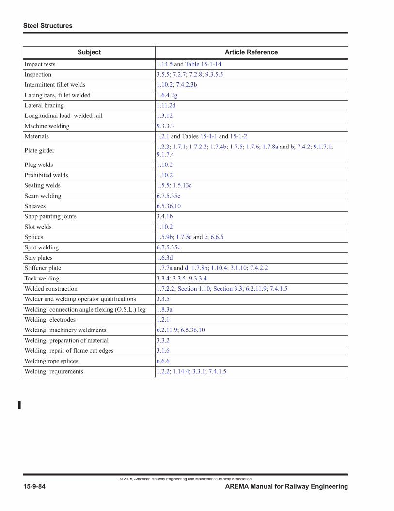
Steel Structures
© 2015, American Railway Engineering and Maintenance-of-Way Association
15-9-84 AREMA Manual for Railway Engineering
Impact tests 1.14.5 and Table 15-1-14Inspection 3.5.5; 7.2.7; 7.2.8; 9.3.5.5Intermittent fillet welds 1.10.2; 7.4.2.3bLacing bars, fillet welded 1.6.4.2gLateral bracing 1.11.2dLongitudinal load–welded rail 1.3.12Machine welding 9.3.3.3Materials 1.2.1 and Tables 15-1-1 and 15-1-2
Plate girder 1.2.3; 1.7.1; 1.7.2.2; 1.7.4b; 1.7.5; 1.7.6; 1.7.8a and b; 7.4.2; 9.1.7.1;9.1.7.4
Plug welds 1.10.2Prohibited welds 1.10.2Sealing welds 1.5.5; 1.5.13cSeam welding 6.7.5.35cSheaves 6.5.36.10Shop painting joints 3.4.1bSlot welds 1.10.2Splices 1.5.9b; 1.7.5c and c; 6.6.6Spot welding 6.7.5.35cStay plates 1.6.3dStiffener plate 1.7.7a and d; 1.7.8b; 1.10.4; 3.1.10; 7.4.2.2Tack welding 3.3.4; 3.3.5; 9.3.3.4Welded construction 1.7.2.2; Section 1.10; Section 3.3; 6.2.11.9; 7.4.1.5Welder and welding operator qualifications 3.3.5Welding: connection angle flexing (O.S.L.) leg 1.8.3aWelding: electrodes 1.2.1Welding: machinery weldments 6.2.11.9; 6.5.36.10Welding: preparation of material 3.3.2Welding: repair of flame cut edges 3.1.6Welding rope splices 6.6.6Welding: requirements 1.2.2; 1.14.4; 3.3.1; 7.4.1.5
Subject Article Reference
© 2015, American Railway Engineering and Maintenance-of-Way Association
© 2014, American Railway Engineering and Maintenance-of-Way Association© 2015, American Railway Engineering and Maintenance-of-Way Association

© 2014, American Railway Engineering and Maintenance-of-Way Association© 2015, American Railway Engineering and Maintenance-of-Way Association

© 2014, American Railway Engineering and Maintenance-of-Way Association© 2015, American Railway Engineering and Maintenance-of-Way Association

© 2014, American Railway Engineering and Maintenance-of-Way Association© 2015, American Railway Engineering and Maintenance-of-Way Association
© 2014, American Railway Engineering and Maintenance-of-Way Association© 2015, American Railway Engineering and Maintenance-of-Way Association

© 2014, American Railway Engineering and Maintenance-of-Way Association© 2015, American Railway Engineering and Maintenance-of-Way Association
© 2014, American Railway Engineering and Maintenance-of-Way Association© 2015, American Railway Engineering and Maintenance-of-Way Association
© 2014, American Railway Engineering and Maintenance-of-Way Association© 2015, American Railway Engineering and Maintenance-of-Way Association
© 2014, American Railway Engineering and Maintenance-of-Way Association© 2015, American Railway Engineering and Maintenance-of-Way Association
© 2015, American Railway Engineering and Maintenance-of-Way Association 15-R-1
1
3
15m15References
— 2015 —
The following list of references used in Chapter 15, Steel Structures is placed here in alphabetical order for your convenience. References includes only the specific material used in developing or explaining recommended practice requirements. In most cases, these requirements are supported by studies and tests reported in other engineering literature.
1. Akesson, B., and B. Edlund. “Fatigue Life of Riveted Railway Bridges.” Proceedings of IABSE Symposium on Extending the Lifespan of Structures, San Francisco, 1995. Vol. 2. Zurich, Switzerland: International Association for Bridge and Structural Engineering, 1995. pp. 1079–1984. Cited in Articles 9.7.3.3.2c(3), and 9.7.3.3.2c(5).
2. Akhtar, M., D. Otter, and B. Doe. “Preliminary Impact Loads Assessment of Ballast Deck Prestressed Concrete Bridges.” Technology Digest TD-05-013. Pueblo, CO: Association of American Railroads/Transportation Technology Center, Inc., May 2005. Cited in Articles 8.3.1a, and 9.8.3.1a.
3. Akhtar, M., D. Otter, and B. Doe. “The Effects of Moveable Bridge Joint on the Fatigue Life of Welded Braces of Open Deck Steel Bridge at FAST.” Technology Digest TD-07-037. Pueblo, CO: Association of American Railroads/Transportation Technology Center, Inc., November 2007. Cited in Articles 8.3.1a and 9.8.3.1a.
4. American Association of State Highway and Transportation Officials. AASHTO LRFD Bridge Design Specifications. 3rd ed. Washington, DC: American Association of State Highway and Transportation Officials, 2004. Cited in Article 9.1.9.4a.
5. American Association of State Highway and Transportation Officials. Movable Bridge Inspection, Evaluation, and Maintenance Manual. 1st ed. Washington, DC: American Association of State Highway and Transportation Officials, 1998. Cited in Article 7.2.1c.
6. American Association of State Highway and Transportation Officials. Standard Specifications for Highway Bridges.17th ed. Washington, DC: American Association of State Highway and Transportation Officials, 2002. Cited in Articles 9.5.1.2b, and 9.5.1.5a.
7. American Association of State Highway Officials. Standard Specifications for Highway Bridges (Interim Specifications 1966-1967). Washington, DC: American Association of State Highway Officials, 1966. Cited in Article 9.1.4.1.
8. American Institute of Steel Construction. AISC Specifications for the Design, Fabrication and Erection of Steel for Buildings. Art. 1.5.1.3. Chicago, IL: American Institute of Steel Construction, April 17, 1963. Cited in Article 9.1.4.1.
9. American Institute of Steel Construction. Bridge Fatigue Guide-Design and Details. Chicago, IL: American Institute of Steel Construction, 1977. Cited in Articles 9.1.3.13g, and 9.1.3.13h.
10. American Institute of Steel Construction. Load and Resistance Factor Design Specification for Structural Steel Buildings. Chicago, IL: American Institute of Steel Construction, December 27, 1999. pp. 67, 68, 246-248. Cited in Article 9.1.5.9e.
© 2015, American Railway Engineering and Maintenance-of-Way Association
15-R-2 AREMA Manual for Railway Engineering
11. American Institute of Steel Construction. Manual of Steel Construction. 14th ed. Chicago, IL: American Institute of Steel Construction, 2011. p. 15-20 (Table 15-8) cited in Article 9.1.12.1c.
12. American Institute of Steel Construction. Manual of Steel Construction: Allowable Stress Design. 8th ed. Chicago, IL: American Institute of Steel Construction, 1978. Cited in Article 9.1.4.1.
13. American Institute of Steel Construction. Manual of Steel Construction: Allowable Stress Design. 9th ed. Chicago, IL: American Institute of Steel Construction, 1989. Cited in Article 9.1.4.1.
14. American Institute of Steel Construction. Manual of Steel Construction: Load and Resistance Factor Design. 2nd ed.Chicago, IL: American Institute of Steel Construction, 1994. Cited in Article 9.1.4.1.
15. American Institute of Steel Construction. Manual of Steel Construction: Load and Resistance Factor Design, 3rd ed. Chicago, IL: American Institute of Steel Construction, 2003. Cited in Article 9.1.9.4a.
16. American Institute of Steel Construction. Specification for Structural Steel Buildings. Chicago, IL: American Institute of Steel Construction, June 22, 2010. pp. 16.1-129, 16.1-411 - 16.1-413. Cited in Article 9.1.5.9e.
17. American Railway Engineering and Maintenance-of-Way Association. AREMA Bridge Inspection Handbook. Lanham, MD: American Railway Engineering and Maintenance-of-Way Association, 2008. Cited in Article 9.7.2.1.
18. American Railway Engineering and Maintenance-of-Way Association. Manual for Railway Engineering. Lanham, MD: American Railway Engineering and Maintenance-of-Way Association, 2012. Cited in Foreword.
19. American Railway Engineering Association. “Bearing Values of Small Rollers, Committee Report.” AREA Proceedings.Vol. 36. Chicago, IL: American Railway Engineering Association, 1935. p. 691. Cited in Articles 9.1.4.1, and 9.5.2.1c.
20. American Railway Engineering Association. “Bibliography and Technical Explanation of Various Requirements in AREA Specifications Relating to Iron and Steel Structures.” AREA Proceedings. Vol. 60. Chicago, IL: American Railway Engineering Association, 1959. p. 535. Cited in Article 9.1.2.5b.
21. American Railway Engineering Association. “Discussion on Iron and Steel Bridges.” AREA Proceedings. Vol. 67. Chicago, IL: American Railway Engineering Association, 1966. pp. 698-699, as illustrated in the following test results: Vol. 44, 1943, p. 29; Vol. 45, 1944, p. 47; Vol. 46, 1945, p. 190; Vol. 47, 1946, p. 207; Vol. 52, 1951, p. 1; Vol. 55, 1954, p. 37; Vol. 57, 1956, p. 15; Vol. 58, 1957, p. 85; Vol. 59, 1958, p. 1; which are summarized in Vol. 61, 1960, p. 51. Cited in Article 9.1.3.5b.
22. American Railway Engineering Association, “Report of Committee 15 - Iron and Steel Strucures.” AREA Proceedings.Vol. 63. Chicago, IL: American Railway Engineering Association, 1962. p. 387. Cited in Article 9.1.2.5b.
23. American Railway Engineering Association, “Report of Committee 15 - Iron and Steel Strucures.” AREA Proceedings.Vol. 69. Chicago, IL: American Railway Engineering Association, 1968. p. 459. Cited in Article 9.1.2.5b.
24. American Railway Engineering Association. “The Shortening of Eyebars to Equalize the Stress, Committee Report.” AREA Proceedings. Vol. 48. Chicago, IL: American Railway Engineering Association, 1947. pp. 969-986. Cited in Articles 8.2.1, 9.8.2.1 and 9.8.2.2o.
25. American Railway Engineering Association. “Tests of Steel Girder Spans and a Concrete Pier on the Santa Fe, Committee Report.” AREA Proceedings. Vol. 58. Chicago, IL: American Railway Engineering Association. pp. 85-169. Cited in Article 1.3.9a.
26. American Railway Engineering Association. “Test Results on Impact, Committee Report.” AREA Proceedings. Vol. 49. Chicago, IL: American Railway Engineering Association, 1948. pp. 207-212. Cited in Articles 9.1.3.5d, and 9.1.3.6a.

© 2015, American Railway Engineering and Maintenance-of-Way Association
AREMA Manual for Railway Engineering 15-R-3
1
3
4
27. American Railway Engineering Association. “Test Results on Relation of Impact to Speed, Committee Report.” AREAProceedings. Vol. 50. Chicago, IL: American Railway Engineering Association, 1949. pp. 432-443. Cited in Articles 7.3.2.3a(1), and 9.1.3.5d.
28. American Society of Civil Engineers. ASCE Transactions. Vol. 128, Part II. New York, NY: American Society of Civil Engineers, 1963. p. 663. Cited in Article 9.1.4.1.
29. American Technical Society. Cyclopedia of Civil Engineering, Vol 3, Steel Construction. Chicago, IL: American Technical Society, 1920. Cited in Article 9.1.9.4a.
30. AREA Committee on Iron and Steel Structures. "Stress Distribution in Bridge Frames - Floorbeam Hangers." AREAProceedings. Vol. 51. Chicago, IL: American Railway Engineering Association, 1950. pp. 470-503. Cited in Articles 9.1.4.1, and 9.7.3.3.2.c(6).
31. Ball, E. F., and J. J. Higgins. “Installation and Tightening of Bolts.” Journal of the Structural Division. Vol. 85, No. ST3. New York, NY: American Society of Civil Engineers, March 1959. pp. 117-132. Cited in Articles 9.3.2.2, and 9.3.2.3.
32. Basler, K. “New Provisions for Plate Girder Design.” Proceedings, AISC National Engineering Conference, New York.Chicago, IL: American Institute of Steel Construction, 1961, pp. 65-74. Cited in Article 9.1.7.8a.
33. Becker, D. N. “Development of the Chicago Type Bascule Bridge, Paper No. 2226.” ASCE Transactions. Vol. 109. New York, NY: American Society of Civil Engineers, 1944. p. 995. Cited in Part 6 Foreword.
34. Bleich, F. Buckling Strength of Metal Structures. New York, NY: McGraw-Hill, 1952. p. 330 cited in Article 9.1.6.2a; p.417 cited in 9.1.7.8a.
35. Brown, J. D., D. J. Lubitz, Y. C. Cekov, K. H. Frank, and P. B. Keating. Evaluation of Influence of Hole Making Upon the Performance of Structural Steel Plates and Connections. Austin, TX: TexDOT, Research and Technology Implementation Office, January 2007. Also FHWA Report FHWA/TX-07/0-4624-1. Cited in Table 15-1-9 Section 1.5, and Table 15-1-9 Section 2.3.
36. Byers, W. G. “Impact From Railway Loading on Steel Girder Spans.” Journal of the Structural Division. New York, NY: American Society of Civil Engineers, June 1970. Cited in Article 9.1.3.13d.
37. Chapin, C. H. “Net Section of Riveted Tension Members.” AREA Proceedings. Vol. 36. Chicago, IL: American Railway Engineering Association, 1935. p. 775. Cited in Article 9.1.5.8.
38. Chesson, E., and W. H. Munse. “Studies of the Behavior of High-Strength Bolts and Bolted Joints.” Bulletin 469.Urbana Champaign, IL: University of Illinois, 1964. Cited in Article 9.1.4.1.
39. Clark, J. W. “Eccentrically Loaded Aluminum Columns.” ASCE Transactions. Vol 120. New York, NY: American Association of Civil Engineers, 1955. Cited in Article 9.1.3.14.1.
40. Clegg, E., and W. G. Blevins. “Wheel Impact Load Detector Experience on CN.” Bulletin 757. Volume 97. Washington, DC: American Railway Engineering Association, October 1996. pp. 499-522. Cited in Article 9.1.3.13d.
41. Column Research Council. Guide to Design Criteria for Metal Compression Members. 2nd ed. New York, NY: John Wiley & Sons, Inc., 1966. p. 25, formula (2.10) cited in Article 9.1.4.1; p. 92, formula (4.3) cited in Article 9.1.4.1.
42. Connor, R. J., E. J. Kaufmann, J. W. Fisher, and W. J. Wright. “Prevention and Mitigation Strategies to Address Recent Brittle Fractures in Steel Bridges.” Journal of Bridge Engineering. Reston, VA: American Society of Civil Engineers, March 2007. Cited in Article 9.1.10.2g.
© 2015, American Railway Engineering and Maintenance-of-Way Association
15-R-4 AREMA Manual for Railway Engineering
43. Connor, R. J., E. J. Kaufmann, J. Jin, C. H. Davies. “Forensic Investigation of the SR 422 over the Schuylkill River Girder Fracture.” 21st Annual International Bridge Conference. Pittsburgh, PA: International Bridge Conference, June 2004. Cited in Article 9.1.10.2g.
44. Dill, F. H. “Structural Steel After A Fire.” Proceedings of the American Institute of Steel Construction Engineering Conference. Chicago, IL: American Institute of Steel Construction, 1960. Cited in Article 8.6.8.
45. Doe, Brian, and Duane Otter. “Hook-Bolt Fastener Performance on the FAST Steel Bridge.” Technology Digest 05-010.Washington, DC: Association of American Railroads, April 2005. Cited in Article 9.8.3.2.1b.
46. Dubas, C. “A Contribution to the Buckling of Stiffened Plates.” IABSE 3rd Congress Preliminary Publication. Liege, Belgium: International Association for Bridge and Structural Engineering, 1948. Cited in Article 9.1.7.8h.
47. Esveld, C. Track Structures in an Urban Environment. Delft, Netherlands: Symposium K. U. Leuven, September 1997. Cited in Article 9.1.3.5a.
48. Federal Highway Adminstration. Bridge Inspector’s Manual for Movable Bridges. Washington, DC: U.S. Department of Transportation, Federal Highway Administration, 1977. Cited in Article 7.2.4.1.
49. Federal Highway Administration. “Uncoated Weathering Steel in Structures.” Technical Advisory T 5140.22.Washington, DC: U.S. Department of Transportation, Federal Highway Administration, October 3, 1989. Cited in Table 15-1-9 Section 1.2.
50. Federal Railroad Administration. “Track Safety Standards.” Code of Federal Regulations Title 49, Part 213, Section 213.55. Washington, DC: U.S. Department of Transportation, Federal Railroad Administration, 2004. Cited in Article 9.1.2.5c.
51. Fisher, J. W., P. A. Albrecht, B. T. Yen, D. J. Klingerman, and B. M. McNamee. “Fatigue Strength of Steel Beams with Transverse Stiffeners and Attachments.” NCHRP Research Results Digest 44. Washington, DC: Transportation Research Board, March 1973. Cited in Article 9.1.3.13h.
52. Fisher, J. W., P. A. Albrecht, B. T. Yen, D. J. Klingerman, and B. M. McNamee. “Fatigue Strength of Steel Beams with Welded Stiffeners and Attachments.” NCHRP Report 147. Washington, DC: Transportation Research Board, 1974. pp. 40 & 41 cited in Article 9.1.3.13g; Cited in Article 9.1.3.13h.
53. Fisher, J. W., and J. H. Daniels. “An Investigation of the Estimated Fatigue in Members of the 380 Ft. Main Span, Fraser River Bridge.” AREA Proceedings. Vol. 77. Chicago, IL: American Railway Engineering Association, 1976. p. 577. Cited in Articles 9.7.3.3.2c(3), and 9.7.3.3.2c(6).
54. Fisher, J. W., K. M. Frank, M. A. Hirt, and B. M. McNamee. “Effect of Weldments on the Fatigue Strength of Steel Beams.” NCHRP Research Results Digest 18. Washington, DC: Transportation Research Board, June 1970. Cited in Article 9.1.3.13h.
55. Fisher, J. W., K. M. Frank, M. A. Hirt, and B. M. McNamee. “Effect of Weldments on the Fatigue Strength of Steel Beams.” NCHRP Report 102. Washington, DC: Transportation Research Board, 1970. Cited in Article 9.1.3.13h.
56. Fisher, J. W., J. Jian, D. C. Wagner, and B. Yen. “Distortion-Induced Fatigue Cracking in Steel Bridges.” NCHRP Report 336. Washington DC: Transportation Research Board, 1990. Cited in Article 9.1.3.13k.
57. Fisher, J. W., D. Mertz, and A. Zhong. “Steel Bridge Members Under Variable Amplitude Long Life Fatigue Loading.” NCHRP Report 267. Washington, DC: Transportation Research Board, 1983. Cited in Article 9.7.3.3.2f&g.
© 2015, American Railway Engineering and Maintenance-of-Way Association
AREMA Manual for Railway Engineering 15-R-5
1
3
4
58. Fisher, J. W., A. Nussbaumer, P. B. Keating, and B. T. Yen. “Resistance of Welded Details Under Variable Amplitude Long-Life Fatigue Loading.” NCHRP Report 354. Washington, DC: Transportation Research Board, 1993. Cited in Article 7.3.3.2g.
59. Fisher, J. W., A. W. Pense, H. Hausammann, and G. R. Irwin. “Quinnipiac River Bridge Cracking.” Journal of the Strucutral Division. Vol. 106, No. ST4. New York, NY: American Socity of Civil Engineers, April 1980. pp. 773-789. Cited in Article 9.7.3.3.2c(2).
60. Fisher, J. W., A. W. Pense, and R. Roberts. “Evaluation of Fracture of Lafayette Street Bridge.” Journal of the Structural Division. Vol. 130, No. ST7. New York, NY: American Socity of Civil Engineers, July 1977. Cited in Article 9.7.3.3.2c(2).
61. Fisher, J. W., B. T. Yen, D. Wang, and J. E. Mann. “Fatigue and Fracture Evaluation for Rating Riveted Bridges.” NCHRP Report 302. Washington, DC: Transportation Research Board, December 1987. Cited in Articles 9.7.3.3.2c(3), 9.7.3.3.2c(4), and 9.7.3.3.2c(7).
62. Foutch, Douglas A., Tae-Wan Kim, Duane E. Otter, and Brian E. Doe. “Investigation of Longitudinal Forces in a Concrete Railroad Trestle.” Journal of Bridge Engineering. Vol. 11, No. 5. Reston, VA: American Society of Civil Engineers, September/October 2006. pp. 618-625. Cited in Articles 9.1.3.12, and 9.7.3.2.8a.
63. Foutch, Douglas A., Daniel H. Tobias, and Duane E. Otter. “Analytical Investigation of the Longitudinal Loads in an Open Deck Through-Plate-Girder Bridge.” Report R-894. Washington, DC: Association of American Railroads, September 1996. Cited in Article 9.1.3.12.
64. Fryba, Ladislav. Dynamics of Railway Bridges. London, England: Thomas Telford Services Ltd., 1996. Cited in Articles 8.3.1a and 9.1.3.12.
65. Galambos, T. V. Guide to Stability Design Criteria for Metal Structures. 4th ed. New York, NY: John Wiley & Sons, Inc., 1988. pp. 89-108. Cited in Article 9.7.3.3.1b.
66. General Electric Company. “Electrical Equipment for Movable Bridges.” Document GEC-1029 17 MB. Schenectady, NY: General Electric Company, 1955. Cited in Part 6 Foreword.
67. Gonzales, K., B. Doe, and D. Davis. “Evaluation of the Effects of Heavy Axle Loads on Rail Joints for Moveable Span Bridges.” Research Summary RS-07-001. Pueblo, CO: Association of American Railroads/Transportation Technology Center, Inc., May 2007. Cited in Articles 8.3.1a, 9.6.2.12d, and 9.8.3.1a.
68. Grinter, L. E. Theory of Modern Structures - Statically Determinate Structures. Vol. 1, Revised. New York, NY: MacMillan Co., 1949. p. 231. Cited in Article 9.1.3.12.
69. Hardash, S. G., and R. Bjorhovde. “New Design Criteria for Gusset Plates in Tension.” Engineering Journal. Vol 22, No. 2. Chicago, IL: American Institute of Steel Construction, 2nd Quarter 1985. pp. 77-94. Cited in Article 9.1.5.9c.
70. Hardesty, E. R., H. W. Fischer, and R. W. Christie. “Fifty-Year History of Movable Bridge Construction – Part I.” Journal of the Construction Division. Vol. 101, No. 3. New York, NY: American Society of Civil Engineers, September 1975, pp. 511-527. Cited in Part 6 Foreword.
71. Hardesty, E. R., H. W. Fischer, and R. W. Christie. “Fifty-Year History of Movable Bridge Construction – Part II.” Journal of the Construction Division. Vol. 101, No. 3. New York, NY: American Society of Civil Engineers, September 1975. pp. 529-543. Cited in Part 6 Foreword.
72. Hardesty, Shortridge. “Live Loads and Unit Stresses.” AREA Proceedings. Vol. 36. Chicago, IL: American Railway Engineering Association, 1935. p. 770. Cited in Article 9.1.3.16.
© 2015, American Railway Engineering and Maintenance-of-Way Association
15-R-6 AREMA Manual for Railway Engineering
73. Hardesty, Shortridge. “Shears on Column Lacing.” AREA Proceedings. Vol. 36. Chicago, IL: American Railway Engineering Association, 1935. p. 724. Cited in Articles 9.1.4.6.1.
74. Hool, G. A., and W. S. Kinne, ed. Movable and Long Span Bridges. 1st ed., 2nd ed. New York, NY: McGraw-Hill, 1924, 1943. Cited in Part 6 Foreword.
75. Hovey, Otis E. “Elastic Stability of Plates Subjected to Compression and Shear.” AREA Proceedings. Vol. 36. Chicago, IL: American Railway Engineering Association, 1935. p. 715. Cited in Articles 9.1.6.1b, 9.1.7.3a, and 9.1.7.8a.
76. Hovey, O. E. Movable Bridges, Vol. I – Structural, Vol. II – Machinery. New York, NY: John Wiley & Sons, Inc., 1927. Cited in Part 6 Foreword.
77. Howard, E. E. “Vertical Lift Bridges, Paper No. 1478.” ASCE Transactions, Vol. LXXXIV. New York, NY: American Society of Civil Engineers, 1921. p. 580. Cited in Part 6 Foreword.
78. Ibrahim, F. I. S. “Load Rating Guidance and Examples for Bolted and Riveted Gusset Plates in Truss Bridges.” FHWA-IF-09-014. Claysburg, PA: FHWA Product Distribution Center, February. 2009. Cited in Article 9.1.5.4b.
79. Jenkins, H. H., et al. “The Effect of Track and Vehicle Parameters on Wheel/Rail Dynamic Forces.” RailwayEngineering Journal. Vol 3, No. 1. London, England: Institute of Mechanical Engineers, January 1974. Cited in Article 9.1.3.5a.
80. Johnston, B. G. “Pin-Connected Plate Links.” ASCE Transactions. New York, NY: American Society of Civil Engineers, 1939. Cited in Article 9.1.4.1.
81. Joy, Richard, Joseph A. LoPresti, and Duane E. Otter. “Longitudinal Forces in a Single-Span, Ballasted-Deck, Plate-Girder Bridge.” Technology Digest TD99-026. Pueblo, CO: Association of American Railroads/Transportation Technology Center, Inc., July 1999. Cited in Article 9.1.3.12.
82. Joy, R., D. Read, and D. Otter. “Continuous Welded Rail Restraint on an Open-Deck Girder Bridge.” Technology Digest TD-07-026. Pueblo, CO: Association of American Railroads/Transportation Technology Center, Inc., September 2007. Cited in Article 9.8.3.3.5.2.
83. Joy, R., D. Read, and D. Otter. “Effects of Continuous Welded Rail on Open-Deck Steel Bridges.” Technology Digest TD-09-021. Pueblo, CO: Association of American Railroads/Transportation Technology Center, Inc., August 2009. Cited in Article 9.8.3.3.5.2.
84. Joy, R., D. Read, D. Otter, and L. Daniels. “Thermal Forces on Open Deck Steel Bridges.” Report R-996. Pueblo, CO: Association of American Railroads/Transportation Technology Center, Inc., May 2009. Cited in Articles 8.3.1a,9.8.3.1a, and 9.8.3.3.5.2.
85. Keating P. B., and J. W. Fisher. “Evaluation of Fatigue Tests and Design Criteria on Welded Details.” NCHRP Report 286. Washington, DC: Transportation Research Board, 1986. Cited in Article 9.1.3.13g.
86. Kulak, G. L., J. W. Fisher, and J. H. Struik. Guide to Design Criteria for Bolted and Riveted Joints. 2nd ed. New York, NY: John Wiley & Sons, Inc., 1987. Chicago, IL: American Institute of Steel Construction/Research Council on Structural Connections, 2001. p. 84 cited in Article 9.1.4.1; pp. 112-115 cited in Article 9.1.9.4a; pp. 123-125 cited in Article 9.1.3.13g; p. 136 cited in Article 9.1.4.1; p. 139 cited in Article 9.1.6.5; pp.186-193 cited in Articles 9.1.5.11a and 9.1.5.11b.
87. Kulak, G. L., and E. Y. Wu. "Shear Lag in Bolted Angle Tension Members." Journal of Structural Engineering. Vol. 123, No. 9. New York, NY: American Society of Civil Engineers, September 1997. pp. 1144-1152. Cited in Article 9.1.6.5.
© 2015, American Railway Engineering and Maintenance-of-Way Association
AREMA Manual for Railway Engineering 15-R-7
1
3
4
88. Kunz, F. C. Design of Steel Bridges. 1st ed. New York, NY: McGraw-Hill, 1915. Cited in Part 6 Foreword.; p. 195 cited in Article 9.1.12.1c.
89. Leffler, B. R. “Specifications for Bridges Movable in Vertical Plane.” ASCE Transactions. Vol. LXXVI. New York, NY: American Socity of Civil Engineers, 1913. p. 370. Cited in Part 6 Foreword.
90. Lie, T. T., and W. W. Stanzak. “Structural Steel and Fire – More Realistic Analysis.” Engineering Journal. Chicago, IL: American Institute of Steel Construction, 1976. Cited in Article 8.6.8.
91. LoPresti, Joseph A., and Duane E. Otter. “Longitudinal Forces in a Two-Span Open-Deck Steel Bridge at FAST.” Technology Digest TD98-020. Washington, DC: Association of American Railroads, August 1998. Cited in Article 9.1.3.12.
92. LoPresti, Joseph A., Duane E. Otter, Daniel H. Tobias, and Douglas A. Foutch. “Longitudinal Forces in an Open-Deck Steel Bridge.” Technology Digest TD98-007. Washington, DC: Association of American Railroads, April 1998. Cited in Article 9.1.3.12.
93. Mahmoud, H. N., R. J. Connor, and J. W. Fisher. “Finite Element Investigation of the Fracture Potential of Highly Constrained Details.” Journal of Computer-Aided Civil and Infrastructure Engineering. Vol. 20. Oxford, England: Blackwell Publishing, 2005. pp. 383-392. Cited in Article 9.1.10.2g.
94. Mazurek, D. F. “Measuring Dead Load Stress of Eyebars in Steel Railroad Bridges.” Proceedings of the AREMA 2011 Annual Conference, Minneapolis, MN. Lanham, MD: American Railway Engineering and Maintenance-of-Way Association, September 2011. Cited in Article 9.8.2.2o.
95. Moisseiff, L., and F. Lienhard. “Theory of Elastic Stability Applied to Structural Design.” ASCE Transactions. Vol. 106. New York, NY: American Society of Civil Engineers, 1941. p. 1052. Cited in Article 9.1.7.8a.
96. Munse, W. H., and E. Chesson. "Riveted and Bolted Joints: Net Section Design." Journal of the Structural Division. Vol. 89, ST1, Part 1. New York, NY: American Society of Civil Engineers, February 1963. Cited in Articles 9.1.4.1, 9.1.6.5, and 9.1.6.6.
97. Munse, W. H., J. E. Stallmeyer, and F. P. Drew. “Structural Fatigue and Steel Railroad Bridges.” AREA Proceedings.Chicago, IL: American Railway Engineering Association, 1968. Cited in Articles 9.1.3.13a, and 9.1.6.6.
98. National Highway Institute. “Fracture Critical Inspection Techniques for Steel Railroad Bridges.” FHWA-NHI 02-037.Arlington, VA: National Highway Institute, January 2002, revised March 2006. Cited in Article 7.2.4.2.
99. Newmark, N. M. and C. P. Siess. “Research on Highway Bridge Floors.” Highway Research Board Proceedings.Washington, DC: National Research Council, 1954. p. 45. Cited in Articles 9.1.11.4a, and 9.1.11.4d-g.
100. Otter, D., and B. Doe. “Bridge Life Extension through Ultrasonic Impact Treatment of Weld Details.” Technology Digest TD-09-030. Pueblo, CO: Association of American Railroads/Transportation Technology Center, Inc., December 2009. Cited in Article 9.7.5.2c.
101. Otter, D., and D. Davis. “Evaluation of a Movable Bridge Rail Joint on the Steel Bridge at FAST.” Technology Digest TD-11-045. Pueblo, CO: Association of American Railroads/Transportation Technology Center, Inc., November 2011. Cited in Article 9.6.2.12d.
102. Otter, Duane, Richard Joy, and Joseph A. LoPresti. “Longitudinal Forces in a Single-Span, Ballasted Deck, Steel Plate Girder Bridge.” Report R-935. Washington, DC: Association of American Railroads, November 1999. Cited in Article 9.1.3.12.
© 2015, American Railway Engineering and Maintenance-of-Way Association
15-R-8 AREMA Manual for Railway Engineering
103. Otter, Duane E., and Joseph LoPresti. “Longitudinal Forces in an Open Deck Steel Deck Plate Girder Bridge.” RailwayTrack & Structures. May 1997. pp. 14-15. Cited in Article 9.1.3.12.
104. Otter, Duane E., and Joseph A. LoPresti. “Longitudinal Forces in Three Open-Deck Steel Bridges.” Proceedings, 1998 Technical Conference. Landover, MD: American Railway Engineering and Maintenance-of-Way Association, September 1998. Cited in Article 9.1.3.12.
105. Otter, Duane E., Joseph LoPresti, Douglas A. Foutch, and Daniel H. Tobias. “Longitudinal Forces in an Open-Deck Steel Deck Plate-Girder Bridge.” Technology Digest TD96-024. Washington, DC: Association of American Railroads, November 1996. Cited in Article 9.1.3.12.
106. Otter, Duane E., Joseph LoPresti, Douglas A. Foutch, and Daniel H. Tobias. “Longitudinal Forces in an Open-Deck Steel Deck Plate-Girder Bridge.” Bulletin 760. Vol. 98. Washington, DC: American Railway Engineering Association, May 1997. pp. 101-105. Cited in Article 9.1.3.12.
107. Otter, Duane E., Joseph A. LoPresti, and Robert A. P. Sweeney. “Longitudinal Forces in Bridges Due to Heavy Haul Freight Operations.” Proceedings, 7th International Heavy Haul Conference. Brisbane, Australia: International Heavy Haul Association, 2001. pp. 565-568. Cited in Article 9.1.3.12.
108. Otter, Duane E., Joseph A. LoPresti, A. Shakoor Uppal, Douglas A. Foutch, and Daniel H. Tobias. “Experimental and Analytical Investigation of the Longitudinal Loads in Open-Deck Plate Girder Railway Bridge.” Research Report R-905. Washington, DC: Association of American Railroads, November 1997. Cited in Article 9.1.3.12.
109. Otter, Duane E., and Robert Sweeney. “Development of guidelines for longitudinal forces in bridges.” Railway Track & Structures. February 2001. pp. 13-15. Cited in Article 9.1.3.12.
110. Otter, D. E., R. A. P. Sweeney, and S. M. Dick. “Development of Design Guidelines for Longitudinal Forces in Bridges.” Technology Digest TD00-018. Pueblo, CO: Association of American Railroads/Transportation Technology Center, Inc., August 2000. Cited in Article 9.1.3.12.
111. Otter, D. E., R. A. P. Sweeney, and S. M. Dick. “New Rating Guidelines for Longitudinal Loads in Steel Bridges.” Technology Digest TD00-014. Pueblo, CO: Association of American Railroads/Transportation Technology Center, Inc., August 2000. Cited in Article 9.7.3.2.8a.
112. Otter, Duane E., A. Shakoor Uppal, and Brian E. Doe. “Longitudinal Forces in a Long Railroad Trestle Bridge.” Technology Digest TD01-021. Pueblo, CO: Association of American Railroads/Transportation Technology Center, Inc., October 2001. Cited in Article 9.1.3.12.
113. Out, J. M. M., J. W. Fisher, and B. T. Yen. “Fatigue Strength of Weathered and Deteriorated Riveted Members.” FinalReport DOT/OST/P-34/85/016. Washington, DC: U. S. Department of Transportation, October 1984. Cited in Articles 9.7.3.3.2c(3), and 9.7.3.3.2c(7).
114. Payne, R. D., and J. F. Unsworth. “Designing for Longitudinal Force.” Proceedings of the AREMA 2006 Annual Conference, Louisville, KY. Lanham, MD: American Railway Engineering and Maintenance-of-Way Association, September 2006. Cited in Article 9.1.3.12.
115. Read, D., D. Otter, and B. Doe. “Reduction of CWR Expansion Joints on a Long Open Deck Bridge.” Technology Digest TD-06-020. Pueblo, CO: Association of American Railroads/Transportation Technology Center, Inc., August 2006. Cited in Article 9.8.3.3.5.2.
116. Reemsnyder, H. S. “Fatigue Life Extension of Riveted Connections.” Journal of the Structural Division. New York, NY: American Society of Civil Engineers, December 1975. Cited in Article 9.7.3.3.2c(3).
© 2015, American Railway Engineering and Maintenance-of-Way Association
AREMA Manual for Railway Engineering 15-R-9
1
3
4
117. Research Council on Structural Connections. Specification for Structural Joints Using ASTM A325 or A490 Bolts.Chicago, IL: American Institute of Steel Construction, June 23, 2000. Cited in Articles 9.1.4.1 and 9.3.2.14.1d.
118. Ricles, J. M., and J. A. Yura. “Strength of Double-Row Bolted Web Connections.” Journal of the Structural Division.Vol. 109, No. ST 1. New York, NY: American Society of Civil Engineers, January 1983. pp. 126-142. Cited in Article 9.1.5.9e.
119. Rockey, K. C., and D. M. A. Leggett. “The Buckling of a Plate Girder Web under Pure Bending When Reinforced by a Single Longitudinal Stiffener.” ICE Proceedings. Vol 21. London, England: Institute of Civil Engineers, 1962. Cited in Articles 9.1.7.3b, and 9.1.7.8g.
120. Roeder, C. W., and J. F. Stanton. “Steel Bridge Bearing Selection and Design Guide.” Highway Structures Design Handbook. Volume II, Chapter 4. Chicago, IL: American Iron and Steel Institute (National Steel Bridge Alliance), December 1996. Cited in Articles 9.5.1.5a, and 9.5.1.5a(7).
121. Roeder, C. W., J. F. Stanton, and T. Feller. “Low Temperature Behavior and Acceptance Criteria for Elastometric Bridge Bearings.” NCHRP Report 325. Washington, DC: Transportation Research Board, December 1989. Cited in Article 5.6.1a.
122. Roeder, C.W., J. F. Stanton, and A. W. Taylor. “Performances of Elastometric Bearings.” NCHRP Report 298.Washington, DC: Transportation Research Board, October 1987. Cited in Article 5.6.1a.
123. Roy, Sougata, J.W. Fisher, and B.T. Yen. “Fatigue Resistance of Welded Details Enhanced by Ultrasonic Impact Treatment (UIT).” Proceedings of the Eleventh International Offshore and Polar Engineering Conference, Vol. IV.Stavanger, Norway: International Society of Offshore and Polar Engineers (ISOPE), June 2001. pp. 309-313. Cited in Article 9.7.5.2c.
124. Ruble, E. J., “Impact In Railroad Bridges.” ASCE Proceedings. Separate No. 736. New York, NY: American Society of Civil Engineers, July 1955. Cited in Article 9.1.3.5a.
125. Rumpf, J. L., and J. W. Fisher. “Calibration of A 325 Bolts.” Journal of the Structural Division. Vol. 89, No. ST6. New York, NY: American Society of Civil Engineers, December 1963. pp. 215-234. Cited in Articles 9.3.2.2, and 9.3.2.3.
126. Salmon, C. G., and J. E. Johnson. Steel Structures, Design and Behavior. 3rd ed.. New York, NY: Harper & Row, 1990. pp. 676–689. Cited in Article 9.7.3.3.1b.
127. Sanders, W. W., Jr., and W. H. Munse. “Load Distribution in Steel Railway Bridges.” Journal of the Structural Division.Vol. 95, No. ST12. New York, NY: American Society of Civil Engineers, December 1969. pp. 2763-2781. Cited in Article 9.1.3.4 footnote.
128. Sasaoka, Charity, D. Davis, D. Otter, and B. Doe. “Evaluation of Specialized Rail Joints for Movable Bridges under HAL Traffic.” Technology Digest 02-016. Washington, DC: Association of American Railroads, July 2002. Cited in Article 9.1.2.14.
129. Schilling, C. G., K. M. Klippstein, J. M. Barsom, and G. T. Blake. “Fatigue of Welded Steel Bridge Members Under Variable-Amplitude Loadings.” NCHRP Research Results Digest 60. Washington, DC: Transportation Research Board, April 1974. p. 4, Figs. 6 and 7. Cited in Article 9.1.3.13g.
130. Schirmer Engineering Corporation, Rolf Jensen and Associates, Inc. Fire Experience and Exposure in Fixed-Guideway Transit Systems (Prepared for American Iron and Steel Institute). Washington, DC: Transportation Research Board, December 1980. Cited in Article 8.6.8.
131. Schneider, C. C. “Movable Bridges, Paper No. 1071.” ASCE Transactions. Vol. LX. New York, NY: American Society of Civil Engineers, June 1908. p. 258. Cited in Part 6 Foreword.
© 2015, American Railway Engineering and Maintenance-of-Way Association
15-R-10 AREMA Manual for Railway Engineering
132. Siegal. L. G. “The Severity of Fires in Steel-Frame Buildings.” AISC Engineering Journal. Chicago, IL: American Institute of Steel Construction, October 1967. Cited in Article 8.6.8.
133. Slutter, Roger C., and John W. Fisher. “Fatigue Strength of Shear Connectors.” Highway Research Record No. 147.Washington, DC: National Research Council, 1966. pp. 65-88. Cited in Table 15-1-11a and Articles 9.1.7.9, 9.1.7.9.2, and 9.1.7.9.3.1.
134. Small, Gregory, and Lane Ketler. “Recycling of an Open Deck Half Through Plate Girder Span and Conversion to a Concrete Ballast Deck Through Plate Girder Span.” Proceedings of the AREMA 2006 Annual Conference, Louisville, KY. Lanham, MD: American Railway Engineering and Maintenance-of-Way Association, September 2006. Cited in Article 9.1.11.2c.
135. Stanton, J. F., and C. W. Roeder. “Elastometric Bearings Design, Construction, and Materials.” NCHRP Report 248.Washington, DC: Transportation Research Board, August 1982. Cited in Article 5.6.1a.
136. Stanton, J. F., C. W. Roeder, and T. I. Campbell. “High-Load Multi-Rotational Bridge Bearings.” NCHRP Report 432.Washington, DC: Transportation Research Board, 1999. Cited in Articles 9.5.1.2b, 9.5.1.5a, and 9.5.1.5a(8).
137. Sweeney, Robert A. P., R. Joy, and D. Otter. “Update on CWR on Open Deck Bridges.” Proceedings of the AREMA 2011 Annual Conference, Minneapolis, MN. Landover, MD: American Railway Engineering and Maintenance-of-Way Association, September 2011. Cited in Article 9.8.3.3.5.2.
138. Sweeney, R. A. P., D. Otter, R. Payne, J. Unsworth, J. Helm, and A. Eskuri. AREMA Longitudinal Force Seminar Participant Guide. Landover, MD: American Railway Engineering and Maintenance-of-Way Association, September 2004. Cited in Articles 9.1.3.12, and 9.7.3.2.8a.
139. Sweeney, Robert A. P., and Felton Suthon. “Design and Rating for Longitudinal Force.” Proceedings of the AREMA 2002 Annual Conference, Washington, DC. Landover, MD: American Railway Engineering and Maintenance-of-Way Association, September 2002. Cited in Articles 9.1.3.12, and 9.7.3.2.8a.
140. Tammen, H. C. “Live Loads for Multiple-Track Bridges.” AREA Proceedings. Vol. 36. Chicago, IL: American Railway Engineering Association, 1935. p. 734. Cited in Article 9.1.3.3d.
141. Tobias, D., D. Foutch, K. Lee, D. E. Otter, and J. A. LoPresti. “Experimental and Analytical Investigation of Longitudinal Forces in a Multi-Span Railway Bridge.” Research Report R-927. Washington, DC: Association of American Railroads, March 1999. Cited in Article 9.1.3.12.
142. Trznadel, M. F., B. T. Yen, R. Roberts, A. W. Pense, and J. W. Fisher. “Fracture Resistance of Eyebars on the Liberty Bridge.” Fritz Engineering Laboratory Report 420.1. Bethlehem, PA: Lehigh University, June 1978. Cited in Article 9.7.3.3.2c(6).
143. Tunna, L., R. Joy, and D. Otter. “Evaluation of Ultrasonic Impact Treatment for Steel Bridge Weld Details,” Technology Digest TD-12-020. Pueblo, CO: Association of American Railroads/Transportation Technology Center, Inc., September 2012. Cited in Article 9.7.5.2c.
144. Unsworth, J. F. Design of Modern Steel Railway Bridges. Boca Raton, FL: CRC Press, 2010. p. 381. Cited in 9.1.3.13.1.
145. Unsworth, John, Gregory Small, and Shahab Afhami. “Service Load Investigation of the Composite Behavior of a Ballasted Through Plate Girder Span.” Proceedings of the AREMA 2005 Annual Conference, Chicago, IL. Lanham, MD: American Railway Engineering and Maintenance-of-Way Association, September 2005. Cited in Article 9.1.11.2c.
146. Uppal, A. S. Evaluation and Repair of Fire Damaged Steel Bridges, Special Project Report No. 2, Chicago, IL: American Railway Bridge and Building Association, 1981. Cited in Article 8.6.8.
© 2015, American Railway Engineering and Maintenance-of-Way Association
AREMA Manual for Railway Engineering 15-R-11
1
3
4
147. Uppal, A. Shakoor, Duane E. Otter, Brian E. Doe, Douglas Foutch, and Tae W. Kim. “Investigation of Longitudinal Force in a Long, Concrete Railroad Trestle Subjected to Unit Coal Train Traffic.” Research Report R-958. Washington, DC: Association of American Railroads, August 2002. Cited in Article 9.1.3.12.
148. Uppal, A. S., D. E. Otter, B. E. Doe, D. A. Foutch, and T. W. Kim. “Longitudinal Forces in a Long Railroad Trestle.” Proceedings of the AREMA 2001 Annual Conference, Chicago, IL. Landover, MD: American Railway Engineering and Maintenance-of-Way Association, September 2001. Cited in Article 9.1.3.12.
149. Uppal, A., D. Otter, R. Joy, and B. Doe. “Longitudinal Forces in Bridges Due to Revenue Service Traffic.” Technology Digest TD00-020. Washington, DC: Association of American Railroads, November 2000. Cited in Article 9.1.3.12.
150. Uppal, A. S., D. E. Otter, R. B. Joy, B. E. Doe, J. A. LoPresti, and D. O. Maal. “Longitudinal Forces in Bridges Due to Revenue Service Traffic.” Research Report R-950. Washington, DC: Association of American Railroads, July 2001. Cited in Articles 9.1.3.12, and 9.7.3.2.8a.
151. Uppal, A. S., D. Yoshino, and L. Tehini. “Ultrasonic Impact Treatment of Vertical Stiffener Welds at FAST Bridge.” Technology Digest TD02-013. Pueblo, CO: Association of American Railroads/Transportation Technology Center, Inc., July 2002. Cited in Article 9.7.5.2c.
152. Valtinat, G., and H. Huhn. “Bolted Connections with Hot Dip Galvanized Steel Members with Punched Holes.” ECCS/AISC Workshop - Connections in Steel Structures V: Innovative Steel Connections. Amsterdam, Netherlands: The European Connection for Constructional Steelwork, June 2004. Cited in Table 15-1-9 Section 2.3.
153. VanCleve, H. P. “Mechanical Features of the Vertical-Lift Bridge, Paper No. 1679.” ASME Annual Meeting. New York, NY: American Society of Mechanical Engineers, December 1918. Cited in Part 6 Foreword.
154. Waddell, J. A. L. Bridge Engineering, Vols. I and II. 1st ed. New York, NY: John Wiley & Sons, Inc., 1916. Cited in Part 6 Foreword and Articles 9.1.2.5c, and 9.1.3.7c.
155. Wakiyama, Kozo, and Akio Tatsumi. “Residual Force in High Strength Bolts Subjected to Heat.” Technology Reports.Vol. 29, No. 1488. Osaka, Japan: Osaka University, 1979. Cited in Article 8.6.8.
156. Wattar, F., P. Albrecht, and A. H. Sahli. “End-Bolted Cover Plates.” Journal of Structural Engineering. Vol. 110, No. 6. New York, NY: American Society of Civil Engineers, June 1985. pp. 1235-1249. Cited in Article 9.1.3.13g.
157. Wei, Benjamin C. F. “Load Distribution of Diaphragms in I-Beam Bridges.” Journal of the Structural Division. Vol. 85, No. ST3. New York, NY: American Society of Civil Engineers, 1959. p. 17. Cited in Articles 9.1.11.4a, and 9.1.11.4d-g.
158. Wengenroth, R. H., H. A. Mix, and E. R. Hardesty. “Fifty-Year History of Movable Bridge Construction – Part III.” Journal of the Construction Division. Vol. 101, No. 3. New York, NY: American Society of Civil Engineers, September 1975. pp. 545-557. Cited in Part 6 Foreword.
159. White, M. and B. Thürliman. “Study of Columns with Perforated Cover Plates.” AREA Proceedings. Vol. 58. Chicago, IL: American Railway Engineering Association, 1957. p. 173. Cited in Article 9.1.6.4.1.
160. Wilson, W. M. “Design of Connection Angles for Stringers of Railway Bridges.” AREA Proceedings. Vol. 41. Chicago, IL: American Railway Engineering Association, 1940. p. 889. Cited in Article 9.1.8.3.
161. Wilson, W. M. “Fatigue Strength of Fillet Weld and Plug Weld Connections in Steel Structural Members.” Bulletin No. 350. Vol. 41, No. 30. Urbana, IL: University of Illinois Engineering Experiment Station, March 14, 1944. Cited in Article 9.1.3.13g.
© 2015, American Railway Engineering and Maintenance-of-Way Association
15-R-12 AREMA Manual for Railway Engineering
162. Winter, George. “Discussion of: Strength of Beams as Determined by Lateral Buckling by Karl de Vries” ASCETransactions. Vol. 112. New York, NY: American Society of Civil Engineers, 1947. pp. 1272-1274. Cited in Article 9.1.4.1.
163. Wright, W. J., J. W. Fisher, E. J. Kaufmann. “Failure Analysis of the Hoan Bridge Fractures.” In Mahmoud (ed.) RecentDevelopments in Bridge Engineering. Lisse, Netherlands: Swets & Zeitlinger, 2003. Cited in Article 9.1.10.2g.
164. Wyly, L. T., and M. B. Scott. “An Investigation of Fatigue Failures in Structural Members of Ore Bridges Under Service Loadings.” AREA Proceedings. Vol. 57. Chicago, IL: American Railway Engineering Association, 1955. p. 175. Cited in Article 9.1.3.13g.
165. Yen, B. T., Zhou, Y., Wang, D., and Fisher, J. W. “Fatigue Behavior of Stringer-Floorbeam Connections.” Report 91-07.Bethlehem, PA: Lehigh University, 1991. Cited in Article 9.1.8.3.
166. Zhou, Y. E., B. T. Yen, J. W. Fisher, and R. A. P. Sweeney. “Examination of Fatigue Strength (Sr-N) Curves for Riveted Bridge Members.” Proceedings of the 12th Annual International Bridge Conference. Pittsburgh, PA: Engineers’ Society of Western Pennsylvania, 1995. Cited in Articles 9.7.3.3.2c(3), and 9.7.3.3.2c(5).