arduino rfid door lock - amazon web services · step 1 — arduino rfid door lock build the arduino...
TRANSCRIPT

Arduino RFID Door LockThe circuit consists of 3 separate parts, a Reader to read RFID tags, a Controller to accept data
from the reader and control the output of the RGB LED and the Electric door lock. The door lock isfirst installed in a door and tested with a 9v battery to
Written By: Feitan
Arduino RFID Door Lock
© 2017 www.botsbits.org Page 1 of 8
PARTS:ATmega168 with Arduino Bootloader (1)
Crystal 16MHz (1)
Capacitor Ceramic 22pF (1)
Resistor 10k Ohm 1/6th Watt PTH (1)
Mini Push Button Switch (1)
Triple Output LED RGB - Diffused (1)
RFID Reader ID-12 (1)
RFID Reader Breakout (1)
Break Away Headers - Straight (1)
RFID Tag - 125kHz (1)
TIP31A transistor (1)
Door Fail Secure access control Electric Strike v5 NO (1)
Arduino RFID Door Lock
© 2017 www.botsbits.org Page 2 of 8
Step 1 — Arduino RFID Door Lock
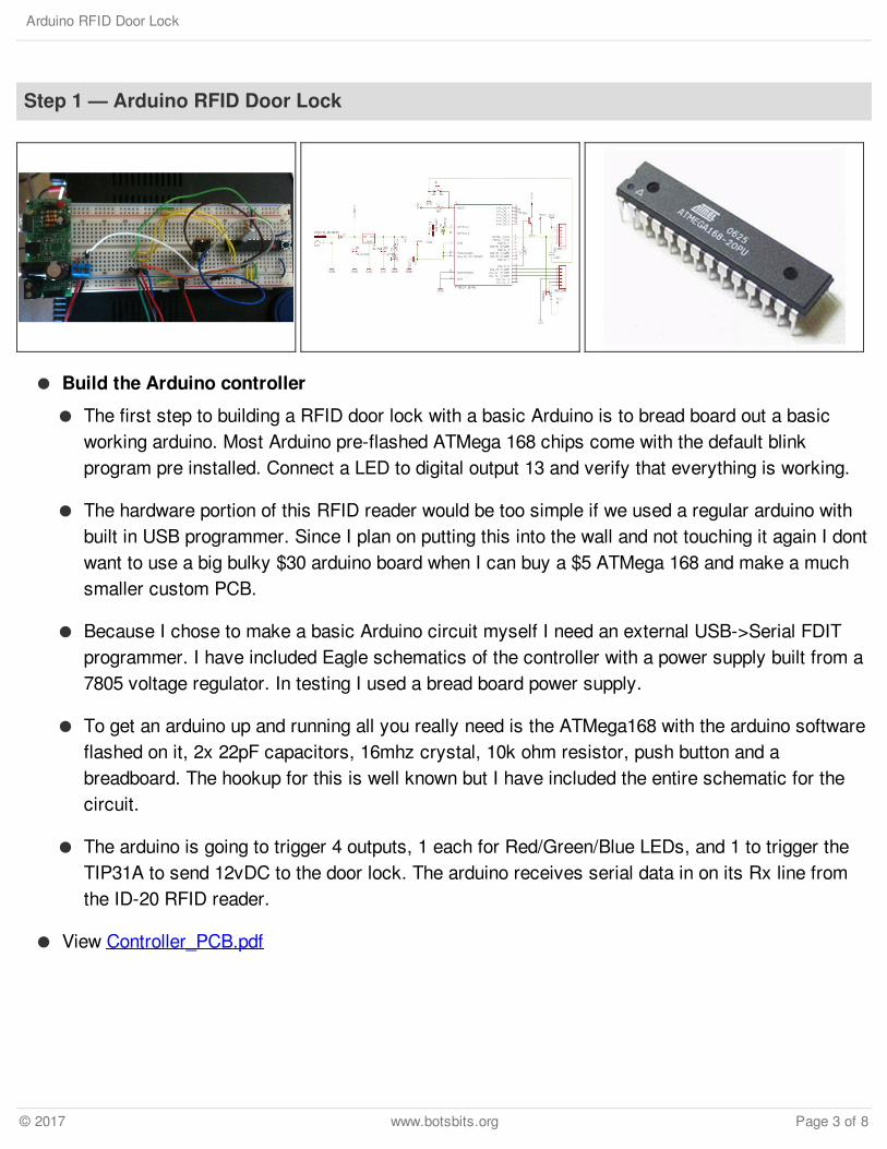
Build the Arduino controller
The first step to building a RFID door lock with a basic Arduino is to bread board out a basicworking arduino. Most Arduino pre-flashed ATMega 168 chips come with the default blinkprogram pre installed. Connect a LED to digital output 13 and verify that everything is working.
The hardware portion of this RFID reader would be too simple if we used a regular arduino withbuilt in USB programmer. Since I plan on putting this into the wall and not touching it again I dontwant to use a big bulky $30 arduino board when I can buy a $5 ATMega 168 and make a muchsmaller custom PCB.
Because I chose to make a basic Arduino circuit myself I need an external USB->Serial FDITprogrammer. I have included Eagle schematics of the controller with a power supply built from a7805 voltage regulator. In testing I used a bread board power supply.
To get an arduino up and running all you really need is the ATMega168 with the arduino softwareflashed on it, 2x 22pF capacitors, 16mhz crystal, 10k ohm resistor, push button and abreadboard. The hookup for this is well known but I have included the entire schematic for thecircuit.
The arduino is going to trigger 4 outputs, 1 each for Red/Green/Blue LEDs, and 1 to trigger theTIP31A to send 12vDC to the door lock. The arduino receives serial data in on its Rx line fromthe ID-20 RFID reader.
View Controller_PCB.pdf
Arduino RFID Door Lock
© 2017 www.botsbits.org Page 3 of 8
Step 2
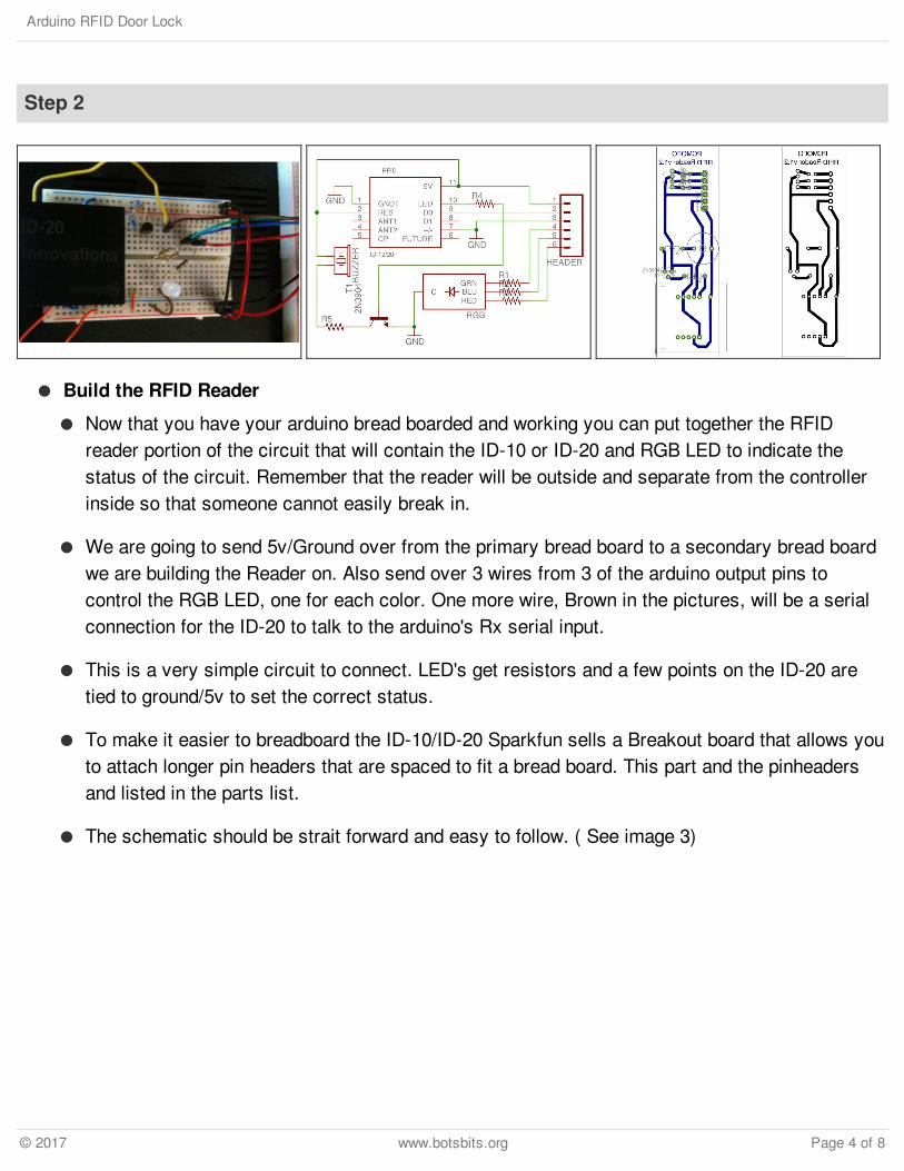
Build the RFID Reader
Now that you have your arduino bread boarded and working you can put together the RFIDreader portion of the circuit that will contain the ID-10 or ID-20 and RGB LED to indicate thestatus of the circuit. Remember that the reader will be outside and separate from the controllerinside so that someone cannot easily break in.
We are going to send 5v/Ground over from the primary bread board to a secondary bread boardwe are building the Reader on. Also send over 3 wires from 3 of the arduino output pins tocontrol the RGB LED, one for each color. One more wire, Brown in the pictures, will be a serialconnection for the ID-20 to talk to the arduino's Rx serial input.
This is a very simple circuit to connect. LED's get resistors and a few points on the ID-20 aretied to ground/5v to set the correct status.
To make it easier to breadboard the ID-10/ID-20 Sparkfun sells a Breakout board that allows youto attach longer pin headers that are spaced to fit a bread board. This part and the pinheadersand listed in the parts list.
The schematic should be strait forward and easy to follow. ( See image 3)
Arduino RFID Door Lock
© 2017 www.botsbits.org Page 4 of 8
Step 3
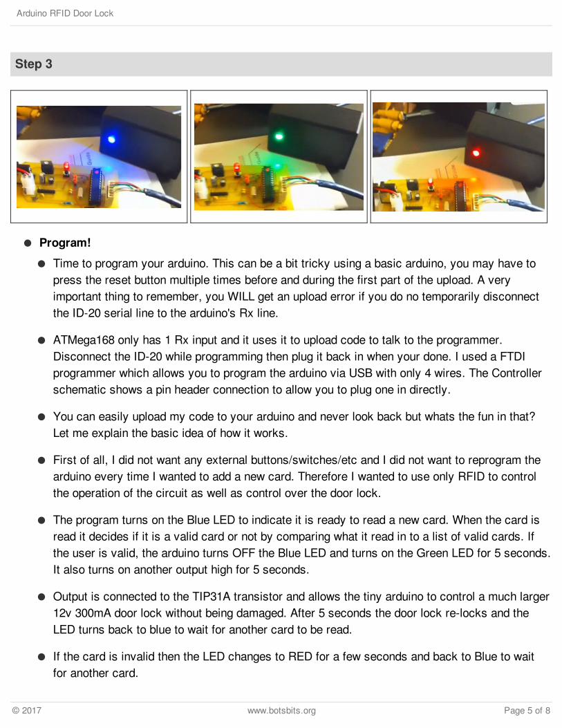
Program!
Time to program your arduino. This can be a bit tricky using a basic arduino, you may have topress the reset button multiple times before and during the first part of the upload. A veryimportant thing to remember, you WILL get an upload error if you do no temporarily disconnectthe ID-20 serial line to the arduino's Rx line.
ATMega168 only has 1 Rx input and it uses it to upload code to talk to the programmer.Disconnect the ID-20 while programming then plug it back in when your done. I used a FTDIprogrammer which allows you to program the arduino via USB with only 4 wires. The Controllerschematic shows a pin header connection to allow you to plug one in directly.
You can easily upload my code to your arduino and never look back but whats the fun in that?Let me explain the basic idea of how it works.
First of all, I did not want any external buttons/switches/etc and I did not want to reprogram thearduino every time I wanted to add a new card. Therefore I wanted to use only RFID to controlthe operation of the circuit as well as control over the door lock.
The program turns on the Blue LED to indicate it is ready to read a new card. When the card isread it decides if it is a valid card or not by comparing what it read in to a list of valid cards. Ifthe user is valid, the arduino turns OFF the Blue LED and turns on the Green LED for 5 seconds.It also turns on another output high for 5 seconds.
Output is connected to the TIP31A transistor and allows the tiny arduino to control a much larger12v 300mA door lock without being damaged. After 5 seconds the door lock re-locks and theLED turns back to blue to wait for another card to be read.
If the card is invalid then the LED changes to RED for a few seconds and back to Blue to waitfor another card.
Arduino RFID Door Lock
© 2017 www.botsbits.org Page 5 of 8
Step 4
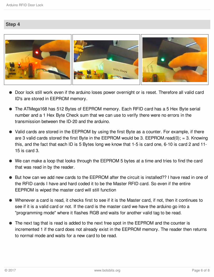
Door lock still work even if the arduino loses power overnight or is reset. Therefore all valid cardID's are stored in EEPROM memory.
The ATMega168 has 512 Bytes of EEPROM memory. Each RFID card has a 5 Hex Byte serialnumber and a 1 Hex Byte Check sum that we can use to verify there were no errors in thetransmission between the ID-20 and the arduino.
Valid cards are stored in the EEPROM by using the first Byte as a counter. For example, if thereare 3 valid cards stored the first Byte in the EEPROM would be 3. EEPROM.read(0); = 3. Knowingthis, and the fact that each ID is 5 Bytes long we know that 1-5 is card one, 6-10 is card 2 and 11-15 is card 3.
We can make a loop that looks through the EEPROM 5 bytes at a time and tries to find the cardthat was read in by the reader.
But how can we add new cards to the EEPROM after the circuit is installed?? I have read in one ofthe RFID cards I have and hard coded it to be the Master RFID card. So even if the entireEEPROM is wiped the master card will still function
Whenever a card is read, it checks first to see if it is the Master card, if not, then it continues tosee if it is a valid card or not. If the card is the master card we have the arduino go into a"programming mode" where it flashes RGB and waits for another valid tag to be read.
The next tag that is read is added to the next free spot in the EEPROM and the counter isincremented 1 if the card does not already exist in the EEPROM memory. The reader then returnsto normal mode and waits for a new card to be read.
Arduino RFID Door Lock
© 2017 www.botsbits.org Page 6 of 8

Currently I have not programmed a way to delete a card as the reasons for deleting a card wouldmost likely be it was lost or stolen. As this would most likely be used with 1-10 people the easiestthing to do would be to hard program a Master Erase card that will wipe all cards from theEEPROM then re add them all, which only takes a few seconds.
Step 5
I have added code to wipe theEEPROM but I have notimplemented this feature yet.
The code is attached in a text filealong with a copy of the parts list.
RFIDLock
Updated_Code
Arduino RFID Door Lock
© 2017 www.botsbits.org Page 7 of 8
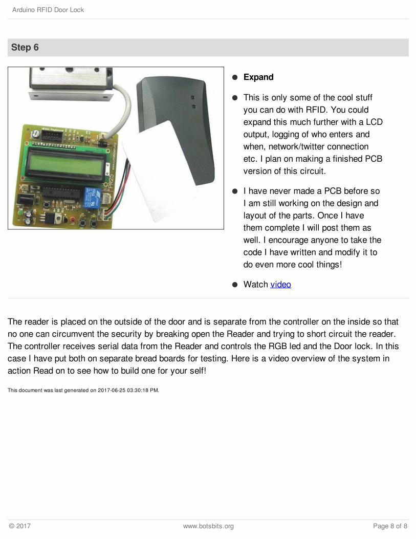
The reader is placed on the outside of the door and is separate from the controller on the inside so thatno one can circumvent the security by breaking open the Reader and trying to short circuit the reader.The controller receives serial data from the Reader and controls the RGB led and the Door lock. In thiscase I have put both on separate bread boards for testing. Here is a video overview of the system inaction Read on to see how to build one for your self!
This document was last generated on 2017-06-25 03:30:18 PM.
Step 6
Expand
This is only some of the cool stuffyou can do with RFID. You couldexpand this much further with a LCDoutput, logging of who enters andwhen, network/twitter connectionetc. I plan on making a finished PCBversion of this circuit.
I have never made a PCB before soI am still working on the design andlayout of the parts. Once I havethem complete I will post them aswell. I encourage anyone to take thecode I have written and modify it todo even more cool things!
Watch video
Arduino RFID Door Lock
© 2017 www.botsbits.org Page 8 of 8