architectural design - unimore - agent and … · ©ian sommerville 2004 ! !software engineering,...
TRANSCRIPT
©Ian Sommerville 2004 Software Engineering, 7th edition. Chapter 11 Slide 1
Architectural Design
©Ian Sommerville 2004 Software Engineering, 7th edition. Chapter 11 Slide 2
Objectives
● To introduce architectural design and to discuss its importance
● To explain the architectural design decisions that have to be made
● To introduce three complementary architectural styles covering organisation, decomposition and control
● To discuss reference architectures are used to communicate and compare architectures
©Ian Sommerville 2004 Software Engineering, 7th edition. Chapter 11 Slide 3
Topics covered
● Architectural design decisions ● System organisation ● Decomposition styles ● Control styles ● Reference architectures
©Ian Sommerville 2004 Software Engineering, 7th edition. Chapter 11 Slide 4
Software architecture
● The design process for identifying the sub-systems making up a system and the framework for sub-system control and communication is architectural design.
● The output of this design process is a description of the software architecture.
©Ian Sommerville 2004 Software Engineering, 7th edition. Chapter 11 Slide 5
Architectural design
● An early stage of the system design process. ● Represents the link between specification
and design processes. ● Often carried out in parallel with some
specification activities. ● It involves identifying major system
components and their communications.
©Ian Sommerville 2004 Software Engineering, 7th edition. Chapter 11 Slide 6
Advantages of explicit architecture
● Stakeholder communication • Architecture may be used as a focus of
discussion by system stakeholders. ● System analysis
• Means that analysis of whether the system can meet its non-functional requirements is possible.
● Large-scale reuse • The architecture may be reusable across a
range of systems.
©Ian Sommerville 2004 Software Engineering, 7th edition. Chapter 11 Slide 7
Architecture and system characteristics ● Performance
• Localise critical operations and minimise communications. Use large rather than fine-grain components.
● Security • Use a layered architecture with critical assets in the inner
layers. ● Safety
• Localise safety-critical features in a small number of sub-systems.
● Availability • Include redundant components and mechanisms for fault
tolerance. ● Maintainability
• Use fine-grain, replaceable components.
©Ian Sommerville 2004 Software Engineering, 7th edition. Chapter 11 Slide 8
Architectural conflicts
● Using large-grain components improves performance but reduces maintainability.
● Introducing redundant data improves availability but makes security more difficult.
● Localising safety-related features usually means more communication so degraded performance.
©Ian Sommerville 2004 Software Engineering, 7th edition. Chapter 11 Slide 9
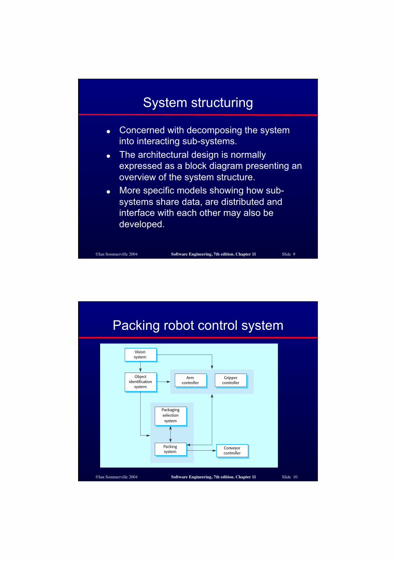
System structuring
● Concerned with decomposing the system into interacting sub-systems.
● The architectural design is normally expressed as a block diagram presenting an overview of the system structure.
● More specific models showing how sub-systems share data, are distributed and interface with each other may also be developed.
©Ian Sommerville 2004 Software Engineering, 7th edition. Chapter 11 Slide 10
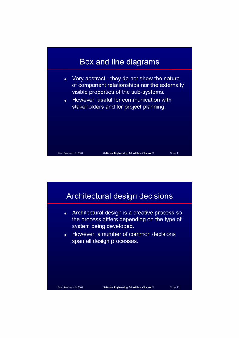
Packing robot control system
©Ian Sommerville 2004 Software Engineering, 7th edition. Chapter 11 Slide 11
Box and line diagrams
● Very abstract - they do not show the nature of component relationships nor the externally visible properties of the sub-systems.
● However, useful for communication with stakeholders and for project planning.
©Ian Sommerville 2004 Software Engineering, 7th edition. Chapter 11 Slide 12
Architectural design decisions
● Architectural design is a creative process so the process differs depending on the type of system being developed.
● However, a number of common decisions span all design processes.
©Ian Sommerville 2004 Software Engineering, 7th edition. Chapter 11 Slide 13
Architectural design decisions
● Is there a generic application architecture that can be used?
● How will the system be distributed? ● What architectural styles are appropriate? ● What approach will be used to structure the system? ● How will the system be decomposed into modules? ● What control strategy should be used? ● How will the architectural design be evaluated? ● How should the architecture be documented?
©Ian Sommerville 2004 Software Engineering, 7th edition. Chapter 11 Slide 14
Architecture reuse
● Systems in the same domain often have similar architectures that reflect domain concepts.
● Application product lines are built around a core architecture with variants that satisfy particular customer requirements.
● Application architectures are covered in Chapter 13 and product lines in Chapter 18.
©Ian Sommerville 2004 Software Engineering, 7th edition. Chapter 11 Slide 15
Architectural styles
● The architectural model of a system may conform to a generic architectural model or style.
● An awareness of these styles can simplify the problem of defining system architectures.
● However, most large systems are heterogeneous and do not follow a single architectural style.
©Ian Sommerville 2004 Software Engineering, 7th edition. Chapter 11 Slide 16
Architectural models
● Used to document an architectural design. ● Static structural model that shows the major system
components. ● Dynamic process model that shows the process
structure of the system. ● Interface model that defines sub-system interfaces. ● Relationships model such as a data-flow model that
shows sub-system relationships. ● Distribution model that shows how sub-systems are
distributed across computers.
©Ian Sommerville 2004 Software Engineering, 7th edition. Chapter 11 Slide 17
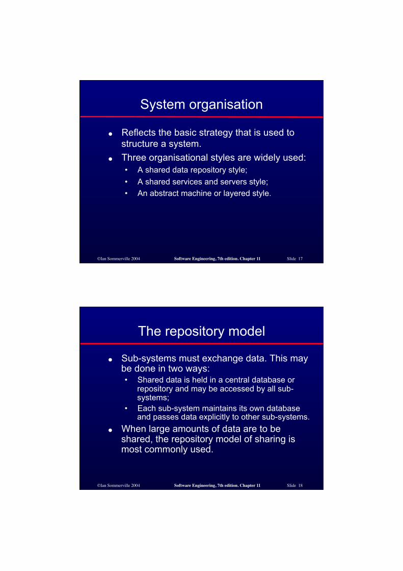
System organisation
● Reflects the basic strategy that is used to structure a system.
● Three organisational styles are widely used: • A shared data repository style; • A shared services and servers style; • An abstract machine or layered style.
©Ian Sommerville 2004 Software Engineering, 7th edition. Chapter 11 Slide 18
The repository model
● Sub-systems must exchange data. This may be done in two ways: • Shared data is held in a central database or
repository and may be accessed by all sub-systems;
• Each sub-system maintains its own database and passes data explicitly to other sub-systems.
● When large amounts of data are to be shared, the repository model of sharing is most commonly used.

©Ian Sommerville 2004 Software Engineering, 7th edition. Chapter 11 Slide 19
CASE toolset architecture
©Ian Sommerville 2004 Software Engineering, 7th edition. Chapter 11 Slide 20
Repository model characteristics
● Advantages • Efficient way to share large amounts of data; • Sub-systems need not be concerned with how data is
produced Centralised management e.g. backup, security, etc.
• Sharing model is published as the repository schema. ● Disadvantages
• Sub-systems must agree on a repository data model. Inevitably a compromise;
• Data evolution is difficult and expensive; • No scope for specific management policies; • Difficult to distribute efficiently.
©Ian Sommerville 2004 Software Engineering, 7th edition. Chapter 11 Slide 21
Client-server model
● Distributed system model which shows how data and processing is distributed across a range of components.
● Set of stand-alone servers which provide specific services such as printing, data management, etc.
● Set of clients which call on these services. ● Network which allows clients to access
servers.
©Ian Sommerville 2004 Software Engineering, 7th edition. Chapter 11 Slide 22
Film and picture library
Impossibile visualizzare l'immagine. La memoria del computer potrebbe essere insufficiente per aprire l'immagine oppure l'immagine potrebbe essere danneggiata. Riavviare il computer e aprire di nuovo il file. Se viene visualizzata di nuovo la x rossa, potrebbe essere necessario eliminare l'immagine e inserirla di nuovo.
©Ian Sommerville 2004 Software Engineering, 7th edition. Chapter 11 Slide 23
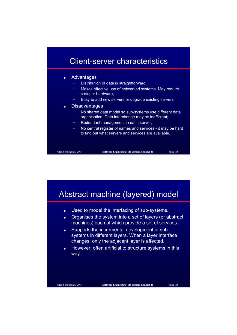
Client-server characteristics
● Advantages • Distribution of data is straightforward; • Makes effective use of networked systems. May require
cheaper hardware; • Easy to add new servers or upgrade existing servers.
● Disadvantages • No shared data model so sub-systems use different data
organisation. Data interchange may be inefficient; • Redundant management in each server; • No central register of names and services - it may be hard
to find out what servers and services are available.
©Ian Sommerville 2004 Software Engineering, 7th edition. Chapter 11 Slide 24
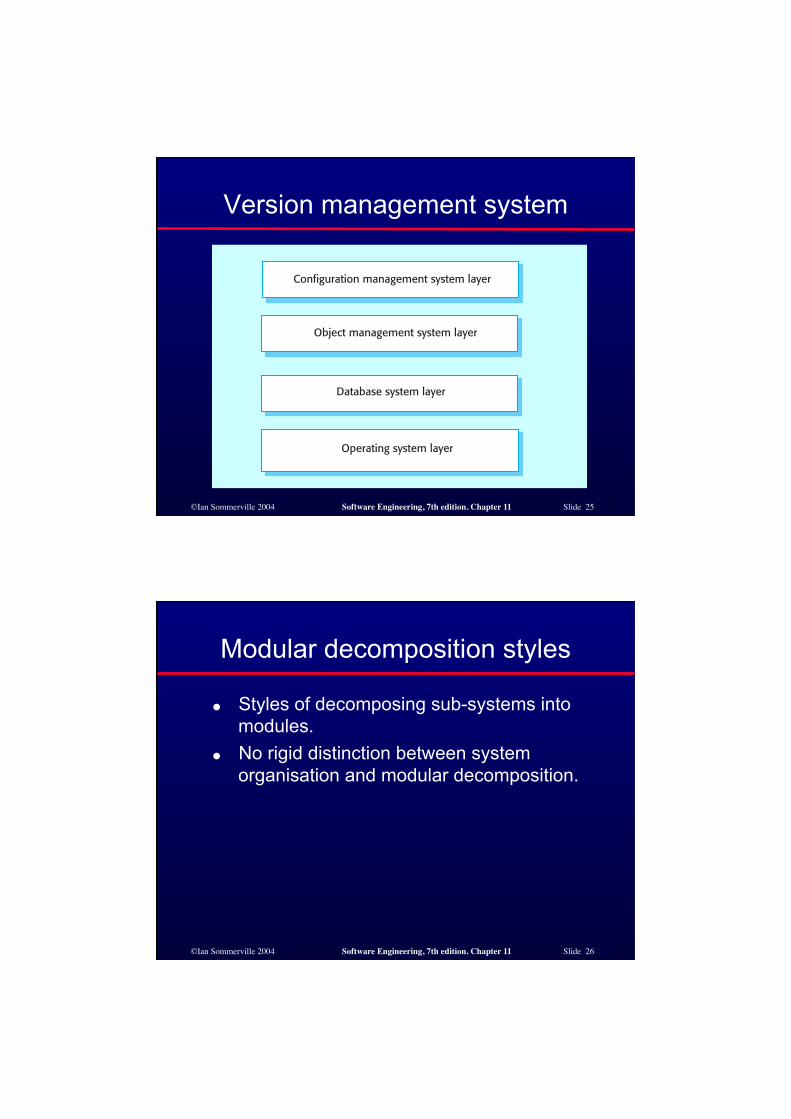
Abstract machine (layered) model
● Used to model the interfacing of sub-systems. ● Organises the system into a set of layers (or abstract
machines) each of which provide a set of services. ● Supports the incremental development of sub-
systems in different layers. When a layer interface changes, only the adjacent layer is affected.
● However, often artificial to structure systems in this way.
©Ian Sommerville 2004 Software Engineering, 7th edition. Chapter 11 Slide 25
Version management system
©Ian Sommerville 2004 Software Engineering, 7th edition. Chapter 11 Slide 26
Modular decomposition styles
● Styles of decomposing sub-systems into modules.
● No rigid distinction between system organisation and modular decomposition.
©Ian Sommerville 2004 Software Engineering, 7th edition. Chapter 11 Slide 27
Sub-systems and modules
● A sub-system is a system in its own right whose operation is independent of the services provided by other sub-systems.
● A module is a system component that provides services to other components but would not normally be considered as a separate system.
©Ian Sommerville 2004 Software Engineering, 7th edition. Chapter 11 Slide 28
Modular decomposition
● Another structural level where sub-systems are decomposed into modules.
● Two modular decomposition models covered • An object model where the system is decomposed into
interacting object; • A pipeline or data-flow model where the system is
decomposed into functional modules which transform inputs to outputs.
● If possible, decisions about concurrency should be delayed until modules are implemented.
©Ian Sommerville 2004 Software Engineering, 7th edition. Chapter 11 Slide 29
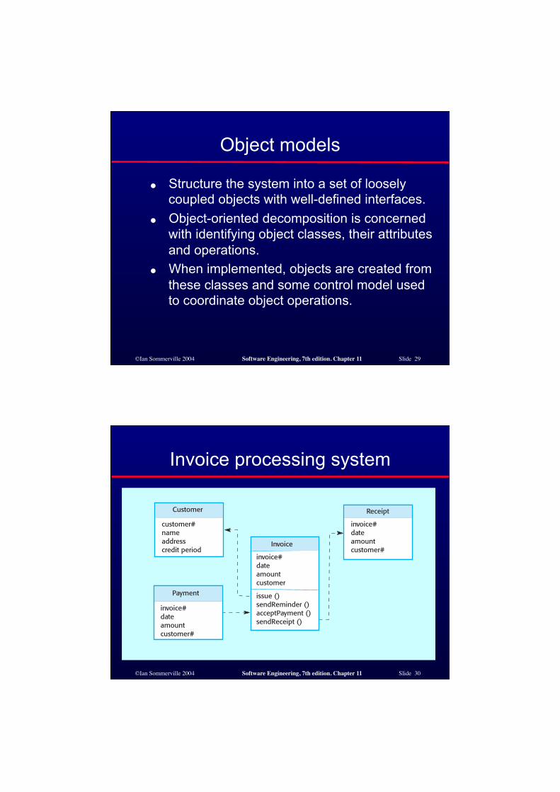
Object models
● Structure the system into a set of loosely coupled objects with well-defined interfaces.
● Object-oriented decomposition is concerned with identifying object classes, their attributes and operations.
● When implemented, objects are created from these classes and some control model used to coordinate object operations.
©Ian Sommerville 2004 Software Engineering, 7th edition. Chapter 11 Slide 30
Invoice processing system
©Ian Sommerville 2004 Software Engineering, 7th edition. Chapter 11 Slide 31
Object model advantages
● Objects are loosely coupled so their implementation can be modified without affecting other objects.
● The objects may reflect real-world entities. ● OO implementation languages are widely
used. ● However, object interface changes may
cause problems and complex entities may be hard to represent as objects.
©Ian Sommerville 2004 Software Engineering, 7th edition. Chapter 11 Slide 32
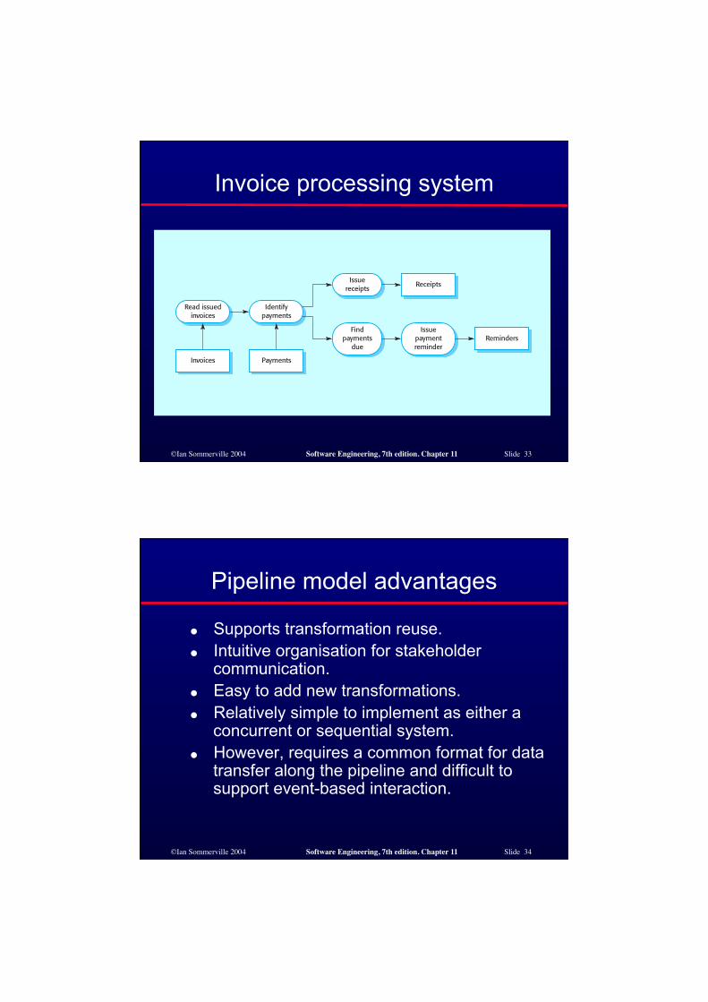
Function-oriented pipelining
● Functional transformations process their inputs to produce outputs.
● May be referred to as a pipe and filter model (as in UNIX shell).
● Variants of this approach are very common. When transformations are sequential, this is a batch sequential model which is extensively used in data processing systems.
● Not really suitable for interactive systems.
©Ian Sommerville 2004 Software Engineering, 7th edition. Chapter 11 Slide 33
Invoice processing system
©Ian Sommerville 2004 Software Engineering, 7th edition. Chapter 11 Slide 34
Pipeline model advantages
● Supports transformation reuse. ● Intuitive organisation for stakeholder
communication. ● Easy to add new transformations. ● Relatively simple to implement as either a
concurrent or sequential system. ● However, requires a common format for data
transfer along the pipeline and difficult to support event-based interaction.
©Ian Sommerville 2004 Software Engineering, 7th edition. Chapter 11 Slide 35
Control styles
● Are concerned with the control flow between sub-systems. Distinct from the system decomposition model.
● Centralised control • One sub-system has overall responsibility for
control and starts and stops other sub-systems. ● Event-based control
• Each sub-system can respond to externally generated events from other sub-systems or the system’s environment.
©Ian Sommerville 2004 Software Engineering, 7th edition. Chapter 11 Slide 36
Centralised control
● A control sub-system takes responsibility for managing the execution of other sub-systems.
● Call-return model • Top-down subroutine model where control starts at the
top of a subroutine hierarchy and moves downwards. Applicable to sequential systems.
● Manager model • Applicable to concurrent systems. One system
component controls the stopping, starting and coordination of other system processes. Can be implemented in sequential systems as a case statement.
©Ian Sommerville 2004 Software Engineering, 7th edition. Chapter 11 Slide 37
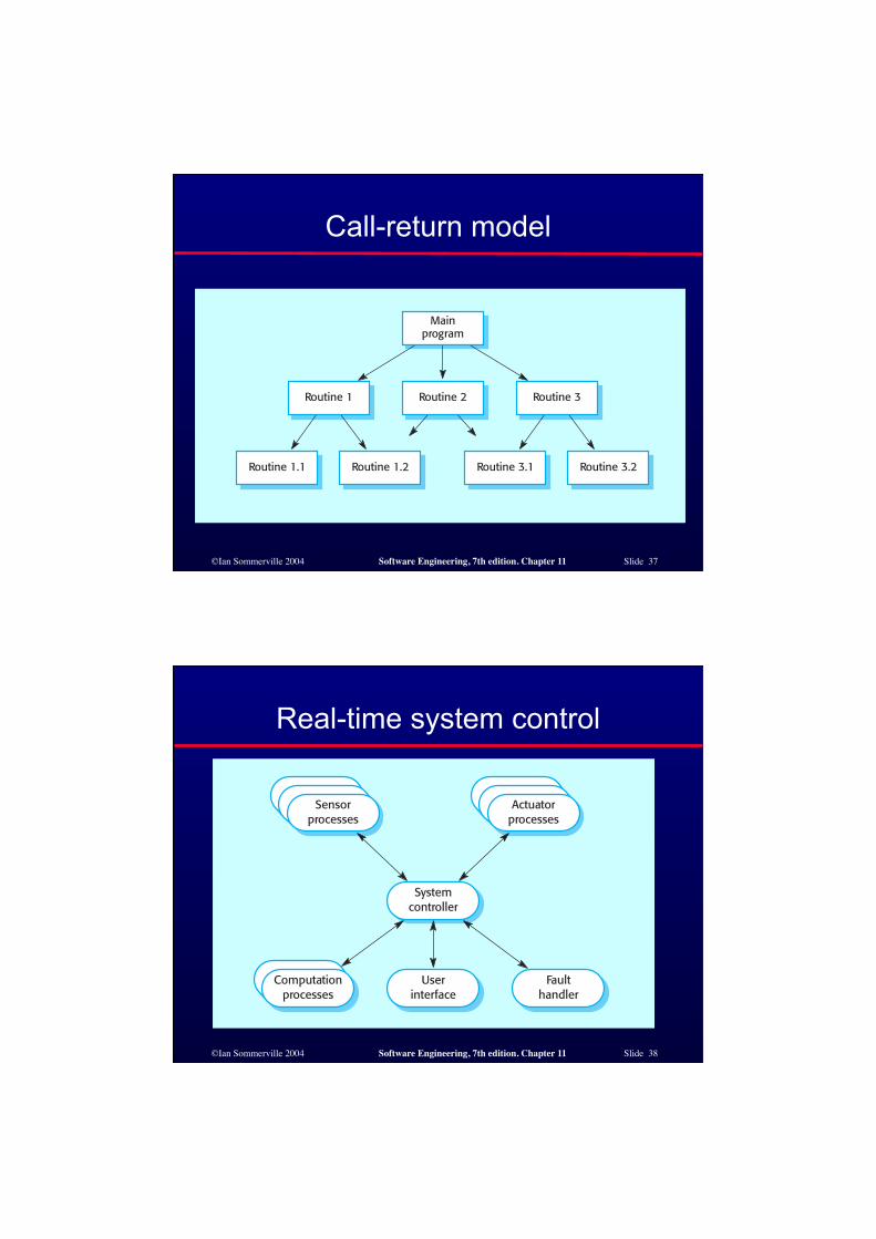
Call-return model
©Ian Sommerville 2004 Software Engineering, 7th edition. Chapter 11 Slide 38
Real-time system control
©Ian Sommerville 2004 Software Engineering, 7th edition. Chapter 11 Slide 39
Event-driven systems
● Driven by externally generated events where the timing of the event is outwith the control of the sub-systems which process the event.
● Two principal event-driven models • Broadcast models. An event is broadcast to all sub-
systems. Any sub-system which can handle the event may do so;
• Interrupt-driven models. Used in real-time systems where interrupts are detected by an interrupt handler and passed to some other component for processing.
● Other event driven models include spreadsheets and production systems.
©Ian Sommerville 2004 Software Engineering, 7th edition. Chapter 11 Slide 40
Broadcast model
● Effective in integrating sub-systems on different computers in a network.
● Sub-systems register an interest in specific events. When these occur, control is transferred to the sub-system which can handle the event.
● Control policy is not embedded in the event and message handler. Sub-systems decide on events of interest to them.
● However, sub-systems don’t know if or when an event will be handled.
©Ian Sommerville 2004 Software Engineering, 7th edition. Chapter 11 Slide 41
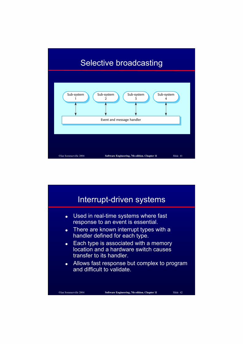
Selective broadcasting
©Ian Sommerville 2004 Software Engineering, 7th edition. Chapter 11 Slide 42
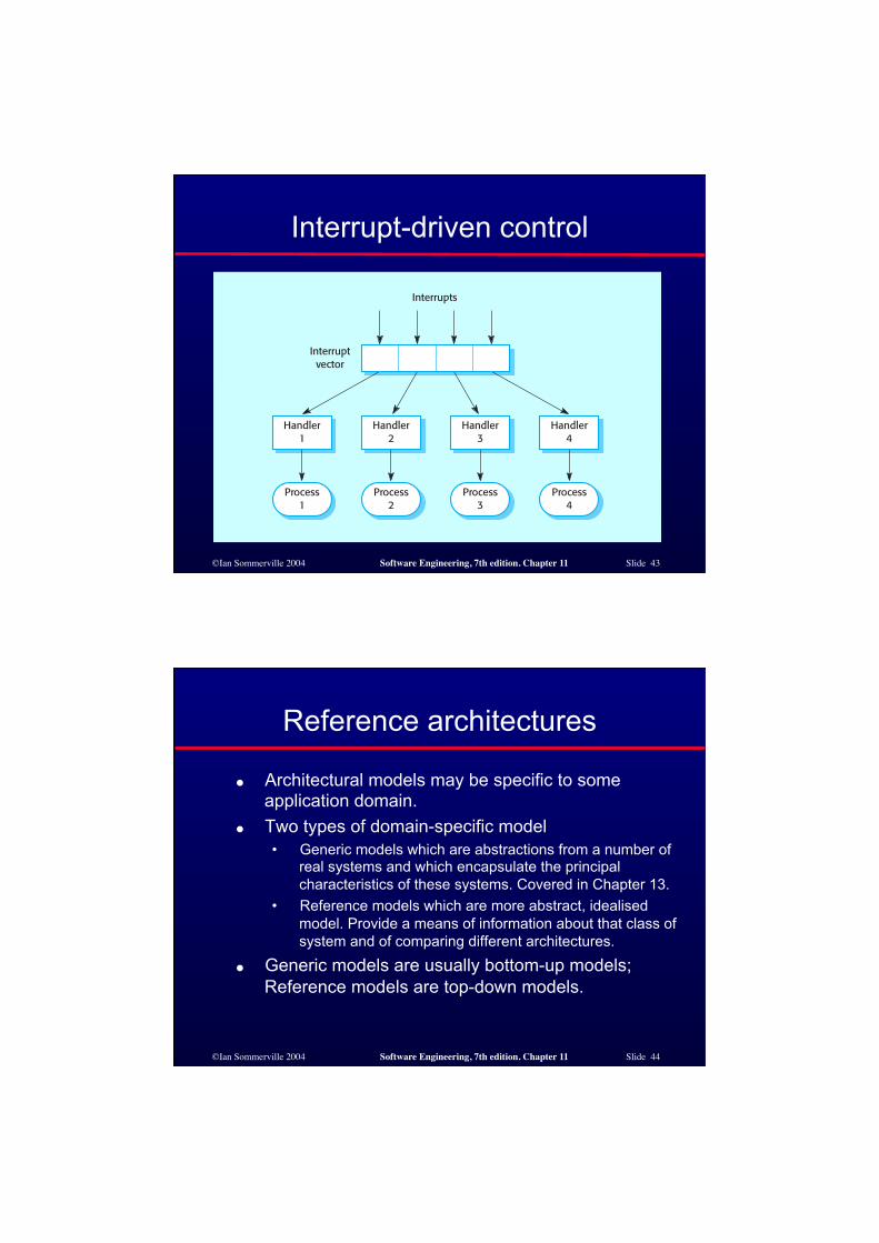
Interrupt-driven systems
● Used in real-time systems where fast response to an event is essential.
● There are known interrupt types with a handler defined for each type.
● Each type is associated with a memory location and a hardware switch causes transfer to its handler.
● Allows fast response but complex to program and difficult to validate.
©Ian Sommerville 2004 Software Engineering, 7th edition. Chapter 11 Slide 43
Interrupt-driven control
©Ian Sommerville 2004 Software Engineering, 7th edition. Chapter 11 Slide 44
Reference architectures
● Architectural models may be specific to some application domain.
● Two types of domain-specific model • Generic models which are abstractions from a number of
real systems and which encapsulate the principal characteristics of these systems. Covered in Chapter 13.
• Reference models which are more abstract, idealised model. Provide a means of information about that class of system and of comparing different architectures.
● Generic models are usually bottom-up models; Reference models are top-down models.
©Ian Sommerville 2004 Software Engineering, 7th edition. Chapter 11 Slide 45
Reference architectures
● Reference models are derived from a study of the application domain rather than from existing systems.
● May be used as a basis for system implementation or to compare different systems. It acts as a standard against which systems can be evaluated.
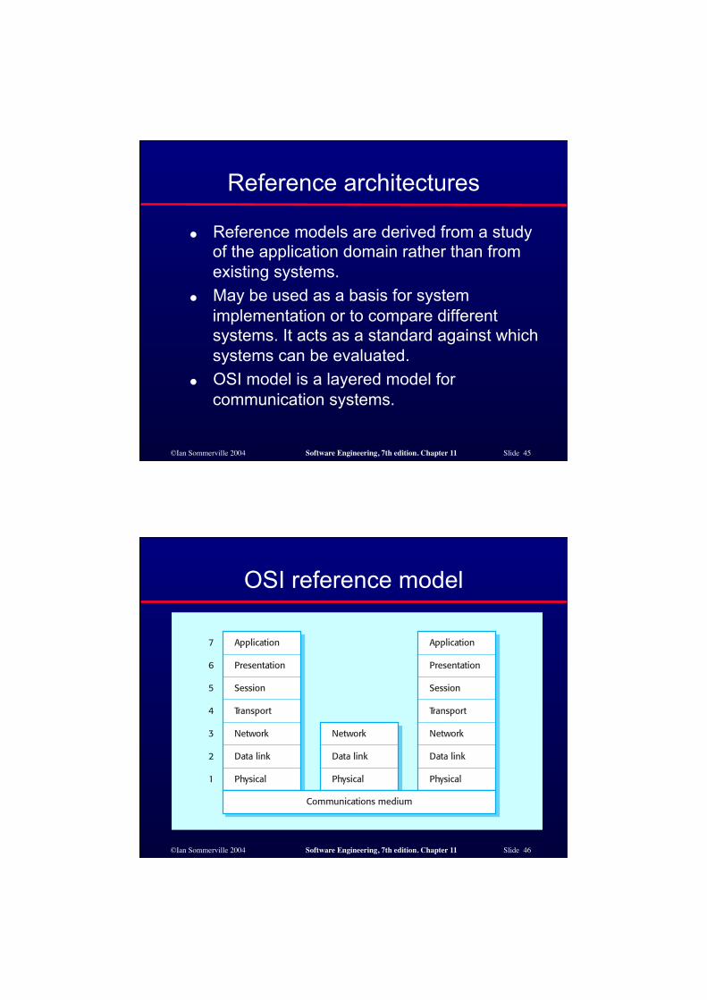
● OSI model is a layered model for communication systems.
©Ian Sommerville 2004 Software Engineering, 7th edition. Chapter 11 Slide 46
OSI reference model
©Ian Sommerville 2004 Software Engineering, 7th edition. Chapter 11 Slide 47
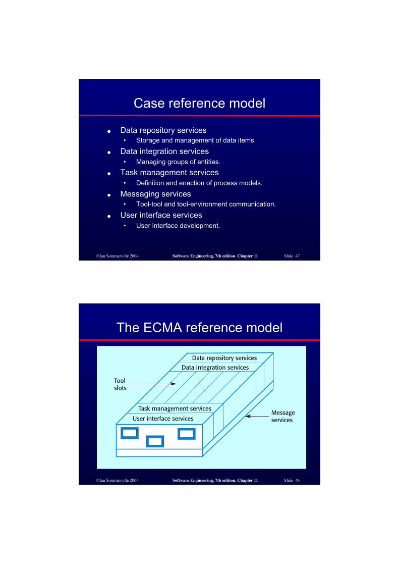
Case reference model
● Data repository services • Storage and management of data items.
● Data integration services • Managing groups of entities.
● Task management services • Definition and enaction of process models.
● Messaging services • Tool-tool and tool-environment communication.
● User interface services • User interface development.
©Ian Sommerville 2004 Software Engineering, 7th edition. Chapter 11 Slide 48
The ECMA reference model
©Ian Sommerville 2004 Software Engineering, 7th edition. Chapter 11 Slide 49
Key points
● The software architecture is the fundamental framework for structuring the system.
● Architectural design decisions include decisions on the application architecture, the distribution and the architectural styles to be used.
● Different architectural models such as a structural model, a control model and a decomposition model may be developed.
● System organisational models include repository models, client-server models and abstract machine models.
©Ian Sommerville 2004 Software Engineering, 7th edition. Chapter 11 Slide 50
Key points
● Modular decomposition models include object models and pipelining models.
● Control models include centralised control and event-driven models.
● Reference architectures may be used to communicate domain-specific architectures and to assess and compare architectural designs.
©Ian Sommerville 2004 Software Engineering, 7th edition. Chapter 11 Slide 51
Architectural models
● Different architectural models may be produced during the design process
● Each model presents different perspectives on the architecture
©Ian Sommerville 2004 Software Engineering, 7th edition. Chapter 11 Slide 52
Architecture attributes
● Performance • Localise operations to minimise sub-system communication
● Security • Use a layered architecture with critical assets in inner layers
● Safety • Isolate safety-critical components
● Availability • Include redundant components in the architecture
● Maintainability • Use fine-grain, self-contained components