architectural and compiler mechanisms for accelerating single thread applications on multicore
TRANSCRIPT

ARCHITECTURAL AND COMPILER MECHANISMS
FOR ACCELERATING SINGLE THREAD APPLICATIONS
ON MULTICORE PROCESSORS
by
Hongtao Zhong
A dissertation submitted in partial fulfillmentof the requirements for the degree of
Doctor of Philosophy(Computer Science and Engineering)
in The University of Michigan2008
Doctoral Committee:Associate Professor Scott Mahlke, ChairAssociate Professor Todd M. AustinAssociate Professor Dennis M. SylvesterAssistant Professor Chandrasekhar BoyapatiMichael S. Schlansker, Hewlett-Packard Laboratories


c© Hongtao Zhong 2008All Rights Reserved

To my parents.
ii
ACKNOWLEDGEMENTS
First, I would like to thank my adviser Professor Scott Mahlke. Scott has been a great
mentor who provided priceless guidance, shown incredible patience and support during
the past years. I consider myself truly lucky to have worked with him. Without his help
and support this dissertation would not exist.
Next, I would like to thank the remaining members of my dissertation committee,
Professor Todd Austin, Professor Dennis Sylvester, Professor Chandrasekhar Boyapati,
and Dr. Mike Schlansker. They all provide invaluable comments and insights to improve
my thesis and shape this research into what is has become today.
The research done in this work utilizes a large software infrastructure maintained
and supported by the CCCP research group. This work would not be possible without
the technical support from everyone in the group. In particular, Steve Lieberman wrote
the first version of the memory profiler in Chapter 5. Mojtaba Mehrara added significant
contribution to this dissertation by spending a great deal of efforts with me developing and
debugging the code generation framework in Chapter 5. The code partitioning algorithm
was based on the Bottom Up Greedy algorithm implemented by Kevin Fan. Mike Chu,
Nate Clark, Kevin Fan, Manjunath Kudlur and Rajiv Ravindrand helped me many times,
answering questions about the Trimaran infrastructure and fixing very hard bugs.
More importantly, all members of the CCCP research group makes my graduate career
much more fun. I would like to thank Jason Blome, Mike Chu, Nate Clark, Ganesh Dasika,
iii

Kevin Fan, Shuguang Feng, Shantanu Gupta, Amir Hormati, Manjunath Kudlur, Steve
Lieberman, Yuan Lin, Mojtaba Mehrara, Robert Mullenix, Pracheeti Nagarkar, Hyunchul
Park, and Mikhail Smelyanskiy for providing invaluable social support, engaging in many
stimulating discussions with me, and giving positive feedback on my research. I also want
to thank all the other friends I have made in Ann Arbor. I couldn’t have finished this
work without all of you.
Finally, I would like to thank my family. My parents provided their unconditional
love, support and encouragement over the years. I wouldn’t have been here without you.
Thank you.
iv

TABLE OF CONTENTS
DEDICATION . . . . . . . . . . . . . . . . . . . . . . . . . . . . . . . . . . . . . ii
ACKNOWLEDGEMENTS . . . . . . . . . . . . . . . . . . . . . . . . . . . . . iii
LIST OF FIGURES . . . . . . . . . . . . . . . . . . . . . . . . . . . . . . . . . . viii
LIST OF TABLES . . . . . . . . . . . . . . . . . . . . . . . . . . . . . . . . . . . xi
ABSTRACT . . . . . . . . . . . . . . . . . . . . . . . . . . . . . . . . . . . . . . xii
CHAPTERS
1 Introduction . . . . . . . . . . . . . . . . . . . . . . . . . . . . . . . . . . 11.1 Contributions . . . . . . . . . . . . . . . . . . . . . . . . . . . . . 31.2 Organization . . . . . . . . . . . . . . . . . . . . . . . . . . . . . . 5
2 Background & Motivation . . . . . . . . . . . . . . . . . . . . . . . . . . . 72.1 Multicore Architecture . . . . . . . . . . . . . . . . . . . . . . . . 72.2 Parallelization Opportunities in Single-thread Applications . . . . 92.3 Overview of Proposed Approach . . . . . . . . . . . . . . . . . . . 15
3 Multicore Architectural Extensions for Exploiting Parallelism in SingleThread Applications . . . . . . . . . . . . . . . . . . . . . . . . . . . . . . 17
3.1 DVLIW: A Multicore Architecture for ILP execution . . . . . . . . 173.1.1 Architecture Overview . . . . . . . . . . . . . . . . . . . . 193.1.2 Intercore Register communication . . . . . . . . . . . . . . 213.1.3 Branch Mechanism . . . . . . . . . . . . . . . . . . . . . . 223.1.4 Example . . . . . . . . . . . . . . . . . . . . . . . . . . . . 253.1.5 Benefits and Potential Problems of the Architecture . . . . 263.1.6 Sleep Mode . . . . . . . . . . . . . . . . . . . . . . . . . . . 273.1.7 Instruction Prefetching . . . . . . . . . . . . . . . . . . . . 303.1.8 Procedure Calls . . . . . . . . . . . . . . . . . . . . . . . . 303.1.9 Scaling Multicluster VLIW with DVLIW . . . . . . . . . . 32
3.2 Voltron: Multicore Extension to Exploit Hybrid Parallelism . . . . 383.2.1 Voltron Architecture Overview . . . . . . . . . . . . . . . . 39
v

3.2.2 Dual-mode Scalar Operand Network . . . . . . . . . . . . . 413.2.3 Voltron Execution Modes . . . . . . . . . . . . . . . . . . . 433.2.4 Memory Dependence Synchronization . . . . . . . . . . . . 49
3.3 Multicore Extension for Speculative LLP . . . . . . . . . . . . . . 503.3.1 Requirements . . . . . . . . . . . . . . . . . . . . . . . . . 513.3.2 Target Architecture . . . . . . . . . . . . . . . . . . . . . . 53
3.4 Related Work . . . . . . . . . . . . . . . . . . . . . . . . . . . . . 57
4 Compiler Techniques for Extracting Fine-grain Parallelism . . . . . . . . . 614.1 Compiling for ILP execution . . . . . . . . . . . . . . . . . . . . . 614.2 Compiling for fine-grain TLP execution . . . . . . . . . . . . . . . 65
5 Compiler Techniques for Uncovering Hidden Loop Level Parallelism inSequential Applications . . . . . . . . . . . . . . . . . . . . . . . . . . . . 70
5.1 Introduction . . . . . . . . . . . . . . . . . . . . . . . . . . . . . . 705.2 Identifying Parallel Opportunities with Control Aware Memory
Profiling . . . . . . . . . . . . . . . . . . . . . . . . . . . . . . . . 735.2.1 Compiler Analysis Challenges . . . . . . . . . . . . . . . . 735.2.2 Design of the Profiler . . . . . . . . . . . . . . . . . . . . . 765.2.3 Profile Results . . . . . . . . . . . . . . . . . . . . . . . . . 795.2.4 Predictability of Cross-Iteration Memory Dependences . . . 82
5.3 Uncovering Hidden Loop Level Parallelism . . . . . . . . . . . . . 845.3.1 Code Generation . . . . . . . . . . . . . . . . . . . . . . . . 845.3.2 Dependence Breaking Optimizations . . . . . . . . . . . . . 88
5.4 Loop Selection . . . . . . . . . . . . . . . . . . . . . . . . . . . . . 995.4.1 Estimating Performance Gain for Individual Loops . . . . . 995.4.2 Loop Selection . . . . . . . . . . . . . . . . . . . . . . . . . 100
5.5 Related Work . . . . . . . . . . . . . . . . . . . . . . . . . . . . . 102
6 Experimental Evaluation . . . . . . . . . . . . . . . . . . . . . . . . . . . 1066.1 Exploiting ILP . . . . . . . . . . . . . . . . . . . . . . . . . . . . . 106
6.1.1 Methodology . . . . . . . . . . . . . . . . . . . . . . . . . . 1066.1.2 Results . . . . . . . . . . . . . . . . . . . . . . . . . . . . . 107
6.2 Exploiting Fine Grain TLP . . . . . . . . . . . . . . . . . . . . . . 1176.2.1 Experimental Methodology . . . . . . . . . . . . . . . . . . 1176.2.2 Results . . . . . . . . . . . . . . . . . . . . . . . . . . . . . 118
6.3 Uncovering Hidden LLP . . . . . . . . . . . . . . . . . . . . . . . . 1206.3.1 Methodology . . . . . . . . . . . . . . . . . . . . . . . . . . 1206.3.2 Results . . . . . . . . . . . . . . . . . . . . . . . . . . . . . 121
6.4 Exploiting Hybrid Parallelism . . . . . . . . . . . . . . . . . . . . 1286.4.1 Experimental Methodology . . . . . . . . . . . . . . . . . . 1286.4.2 Results . . . . . . . . . . . . . . . . . . . . . . . . . . . . . 129
7 Summary . . . . . . . . . . . . . . . . . . . . . . . . . . . . . . . . . . . . 132
vi

BIBLIOGRAPHY . . . . . . . . . . . . . . . . . . . . . . . . . . . . . . . . . . . 134
vii

LIST OF FIGURES
Figure
2.1 A 2 core CMP architecture . . . . . . . . . . . . . . . . . . . . . . . . . . 8
2.2 Example of fine-grain TLP . . . . . . . . . . . . . . . . . . . . . . . . . . . 10
2.3 (a) An loop from 256.bzip2 that usually has no cross-iteration memorydependences. (b) An loop from 124.m88ksim that usually has no cross-iteration memory dependences, but has a cross-iteration control dependence. 12
2.4 Example of Loop Level Parallelism . . . . . . . . . . . . . . . . . . . . . . 13
2.5 Breakdown of exploitable parallelism for a 4-core system. . . . . . . . . . . 14
3.1 Overview of multicore architecture for ILP execution. Four core exampleis shown. . . . . . . . . . . . . . . . . . . . . . . . . . . . . . . . . . . . . . 19
3.2 (a) Code layout on a conventional 4-cluster VLIW architecture. RectangleA0 represents operations in MultiOp A to be executed by cluster 0. (b)Code layout on the proposed multicore architecture. Bold lines representMultiOp boundaries in (a). . . . . . . . . . . . . . . . . . . . . . . . . . . 20
3.3 Example code segment for : (a) Multicluster VLIW, (b) Proposed multicorearchitecture. The leftmost operand is the destination for each assemblyoperation. . . . . . . . . . . . . . . . . . . . . . . . . . . . . . . . . . . . . 23
3.4 Sleep mode example: (a) Original control flow graph, (b) control flowgraphs for a 2-core architecture where core one is in sleep mode for blockstwo through five. Sleep mode is entered via the SLEEP TK operation inBB1 on Cluster 1 and exited via the WAKE operation in BB5 on Cluster 0. 29
3.5 Instruction memory organizations: (a) Centralized instruction cache, un-compressed encoding; (b) Centralized instruction cache, compressed encod-ing; (c) Distributed I-cache, centralized PC, uncompressed encoding; (d)Distributed I-cache, distributed PC, compressed encoding. . . . . . . . . . 36
3.6 Block diagram of the Voltron architecture: (a) 4-core system connectedin a mesh topology, (b) Datapath for a single core, and (c) Details of theinter-core communication unit. . . . . . . . . . . . . . . . . . . . . . . . . 40
3.7 Execution of a distributed branch: (a) Original unbundled branch in HPL-PD, (b) Branch with predicate broadcast, and (c) Branch with the condi-tion computation replicated. . . . . . . . . . . . . . . . . . . . . . . . . . 43
viii
3.8 Code execution under different modes. (a) Control flow graph of a codesegment. (b) Execution of the code segment under coupled mode. (c)Control flow graph of fine-grain threads extracted for decoupled mode. (d)Execution of the code segment under decoupled mode. . . . . . . . . . . . 45
3.9 Block diagram of the target architecture: (a) 4-core system connected in amesh topology, (b) Datapath for a single core . . . . . . . . . . . . . . . . 52
4.1 Compiler flow for ILP extraction . . . . . . . . . . . . . . . . . . . . . . . 62
4.2 Compiling a loop for the Voltron architecture. (a) Original loop in C code.(b) Assembly instructions for the loop. (c) Resulting DFG partition forcoupled mode. (d) Resulting DFG partition for decoupled mode. . . . . . 68
5.1 Fraction of sequential execution covered by DOALL loops identified throughcompiler analysis. . . . . . . . . . . . . . . . . . . . . . . . . . . . . . . . . 74
5.2 Potential speedup for idealized CMP using DOALL loops identified throughcompiler analysis. . . . . . . . . . . . . . . . . . . . . . . . . . . . . . . . . 75
5.3 Caption for flstack-loop-fig. . . . . . . . . . . . . . . . . . . . . . . . . . . 77
5.4 Fraction of sequential execution covered by DOALL loops identified throughprofiling analysis. . . . . . . . . . . . . . . . . . . . . . . . . . . . . . . . . 80
5.5 Potential speedup for idealized CMP using DOALL loops identified throughprofiling analysis. . . . . . . . . . . . . . . . . . . . . . . . . . . . . . . . . 81
5.6 Distribution of execution time for loops with varying fractions of iterationswith cross-iteration dependences. The left bar represents the breakdownof all loops for a training input. The right bar represents the breakdownof the zero cross iteration dependence loops on the training input using alarger, evaluation input for the benchmark. . . . . . . . . . . . . . . . . . . 82
5.7 Detailed code generation framework for speculative loop parallelization.Transaction scope is marked by XBEGIN and XCOMMIT. (CS: chunksize, IS: iteration start, IE: iteration end, SS: step size, TC: thread count) . 86
5.8 Speculative loop fission (a) Original loop (b) Original data flow graph (c)Data flow graph after fission (d) Loop after fission - (rf: register flow de-pendence, c: control dependence, m?: unlikely cross-iteration memory de-pendence . . . . . . . . . . . . . . . . . . . . . . . . . . . . . . . . . . . . . 89
5.9 Example of speculative loop fission from 175.vpr: (a) original loop (b) loopafter fission (c) abort handler. . . . . . . . . . . . . . . . . . . . . . . . . . 91
5.10 Example of speculative prematerialization: (a) original loop, (b) dataflowgraph, and (c) loop after transformation. . . . . . . . . . . . . . . . . . . 93
5.11 Example of speculative prematerialization from djpeg. . . . . . . . . . . . . 95
5.12 Example of dependence isolation: (a) mechanics of transformation for anabstract loop, (b) example loop from yacc. . . . . . . . . . . . . . . . . . . 96
6.1 Speedup for ILP execution. . . . . . . . . . . . . . . . . . . . . . . . . . . 108
6.2 Relative execution time on a 4-cluster DVLIW processor with total I-cachesizes of 16K and 32K. . . . . . . . . . . . . . . . . . . . . . . . . . . . . . . 109
6.3 Reduction in dynamic global communication signals of a 4-cluster DVLIWprocessor. . . . . . . . . . . . . . . . . . . . . . . . . . . . . . . . . . . . . 111
ix

6.4 Relative energy consumption for the instruction fetch subsystem of a 4-cluster DVLIW processor. . . . . . . . . . . . . . . . . . . . . . . . . . . . 112
6.5 Effectiveness of sleep mode on a 4-cluster DVLIW. . . . . . . . . . . . . . 113
6.6 Comparison of the relative code size of 2- and 4-cluster DVLIWs withVLIWs having a distributed I-cache and a shared PC. . . . . . . . . . . . . 114
6.7 Comparison of the relative stall cycles and execution time on a 4-clusterDVLIW with a VLIW having a distributed I-cache and a shared PC. . . . 115
6.8 Speedup for fine-grain TLP execution. . . . . . . . . . . . . . . . . . . . . 118
6.9 Breakdown of synchronization stalls by type on a 4-core system. Eachbenchmark has two bars: the left bar is for decoupled mode and the rightfor coupled mode. . . . . . . . . . . . . . . . . . . . . . . . . . . . . . . . . 119
6.10 Fraction of sequential execution covered by speculative DOALL loops aftertransformations . . . . . . . . . . . . . . . . . . . . . . . . . . . . . . . . . 122
6.11 Effect of the compiler transformations on performance for 2, 4, and 8 coresystems. The bottom portion of each bar shows the baseline with TLS onlyand the top portion shows the combined affects of all transformations. . . . 123
6.12 The first two bars show the effect of inter-core communication throughmemory systems versus scalar operand network. The last bar shows thespeedup without any parallelization overhead. . . . . . . . . . . . . . . . . 124
6.13 Speedup on 2-core and 4-core Voltron exploit hybrid parallelism. . . . . . . 129
6.14 Breakdown of sequential execution time best accelerated by exploiting dif-ferent types of parallelism. . . . . . . . . . . . . . . . . . . . . . . . . . . . 130
x

LIST OF TABLES
Table
3.1 Hardware and software support to meet requirement for statistical looplevel parallelism. . . . . . . . . . . . . . . . . . . . . . . . . . . . . . . . . 56
6.1 Comparison of hardware cost and power consumption for the instructionalign/shift/distribution networks of various VLIW configurations. . . . . . 110
6.2 Percentage sequential code coverage of various transformations – Last col-umn shows the Abort frequencies in the benchmarks. Coverages higherthan 20% are highlighted. (CS:control speculation for uncounted loop,RE: reduction expansion, SF: speculative fission, PM: prematerialization,IDI: infrequent dependence isolation, LD: ignore long distance dependence,AF: abort frequency). . . . . . . . . . . . . . . . . . . . . . . . . . . . . . 126
xi

ABSTRACT
ARCHITECTURAL AND COMPILER MECHANISMS
FOR ACCELERATING SINGLE THREAD APPLICATIONS
ON MULTICORE PROCESSORS
by
Hongtao Zhong
Chair: Scott Mahlke
Multicore systems have become the dominant mainstream computing platform. One
of the biggest challenges going forward is how to efficiently utilize the ever increasing
computational power provided by multicore systems. Applications with large amounts
of explicit thread-level parallelism naturally scale performance with the number of cores.
However, single-thread applications realize little to no gains from multicore systems.
This work investigates architectural and compiler mechanisms to automatically ac-
celerate single thread applications on multicore processors by efficiently exploiting three
types of parallelism across multiple cores: instruction level parallelism (ILP), fine-grain
thread level parallelism (TLP), and speculative loop level parallelism (LLP).
A multicore architecture called Voltron is proposed to exploit different types of paral-
lelism. Voltron can organize the cores for execution in either coupled or decoupled mode.
In coupled mode, several in-order cores are coalesced to emulate a wide-issue VLIW pro-
cessor. In decoupled mode, the cores execute a set of fine-grain communicating threads
extracted by the compiler. By executing fine-grain threads in parallel, Voltron provides
xii

coarse-grained out-of-order execution capability using in-order cores. Architectural mech-
anisms for speculative execution of loop iterations are also supported under the decoupled
mode. Voltron can dynamically switch between two modes with low overhead to exploit
the best form of available parallelism.
This dissertation also investigates compiler techniques to exploit different types of
parallelism on the proposed architecture. First, this work proposes compiler techniques
to manage multiple instruction streams to collectively function as a single logical stream
on a conventional VLIW to exploit ILP. Second, this work studies compiler algorithms to
extract fine-grain threads. Third, this dissertation proposes a series of systematic compiler
transformations and a general code generation framework to expose hidden speculative
LLP hindered by register and memory dependences in the code. These transformations
collectively remove inter-iteration dependences that are caused by subsets of isolatable
instructions, are unwindable, or occur infrequently.
Experimental results show that proposed mechanisms can achieve speedups of 1.33
and 1.14 on 4 core machines by exploiting ILP and TLP respectively. The proposed
transformations increase the DOALL loop coverage in applications from 27% to 61%,
resulting in a speedup of 1.84 on 4 core systems.
xiii
CHAPTER 1
Introduction
Since the earliest processors came onto the market, the semiconductor industry has
depended on Moore’s Law to deliver consistent application performance gains through the
multiplicative effects of increased transistor counts and higher clock frequencies. How-
ever, power dissipation and design complexity issues have emerged as dominant design
constraints that severely restrict the ability to increase clock frequency or utilize more
complex out-of-order mechanisms to improve performance. Exponential growth in tran-
sistor counts still remains intact and a powerful tool to improve performance. This trend
has led major microprocessor companies to put multiple processors onto a single chip.
One of the most difficult challenges going forward is software: if the number of devices
per chip continues to grow with Moore’s law, can the available hardware resources be
converted into meaningful application performance gains?
In some regards, the embedded and domain-specific communities have pulled ahead of
the general-purpose world in taking advantage of available parallelism, as most system-
on-chip designs have consisted of multiple processors and hardware accelerators for some
time. However, these system-on-chip designs are often deployed for limited application
spaces, requiring hand-generated assembly and tedious programming models. The lack of
1
necessary compiler technology is increasingly apparent as the push to run general-purpose
software on multicore platforms is required.
Multicore systems increase throughput and efficiency by utilizing multiple cores to
perform computation in parallel and complete a larger volume of work in a shorter period
of time. Such designs are ideal for servers where coarse thread-level parallelism (TLP)
is abundant. But for systems where single-threaded applications dominate, multicore
systems offer very limited benefits. Single-thread performance is still important in the
multicore era for several reasons. First, a large amount of existing applications are writ-
ten as single thread programs, future systems must provide ways to run them efficiently.
Second, past experiences have shown that it is much easier to write and maintain sequen-
tial programs than parallel programs; automatically accelerate single thread applications
can relieve programmers from the burden of writing explicit parallel programs. Third,
Amdahl’s law states that the maximum speedup can be achieved for a given application
is limited by the sequential portion of the program. Improving single-thread performance
for the sequential portion is also important for parallel programs.
Until recently, utilizing multicore hardware requires manually writing parallel pro-
grams. Extracting TLP from general-purpose applications is difficult for a variety of
reasons that span both the design limitations of current multicore systems and the char-
acteristics of the applications themselves. On the hardware side, processors in multicore
systems communicate through memory, resulting in long latency and limited bandwidth
communication. Synchronization of the processors is also performed through memory,
thereby causing a high overhead for synchronization. Finally, multicore systems do not
support exploiting instruction-level parallelism (ILP) in an efficient manner. In short,
current multicores are generally direct extensions of shared-memory multiprocessors that
are designed to efficiently execute coarse-grain threads. On the application side, the abun-
2

dance of dependences, including data, memory, and control dependences, severely restrict
the amount of parallelism that can be extracted from general-purpose programs. The
frequent use of pointers and linked data structures is a particularly difficult problem to
overcome even with sophisticated memory alias analysis [53]. Coarse-grain parallelism
often cannot be discovered from general-purpose applications. Frequent communication
and synchronization along with modest amounts of parallelism are dominant characteris-
tics. Thus, there is a distinct mismatch between multicore hardware and general-purpose
software.
In this dissertation, architectural and compiler techniques are proposed to acceler-
ate single thread applications on multicore systems by exploiting hybrid forms of par-
allelisms. Different types of parallelism, including instruction level parallelism (ILP),
fine-grain thread level parallelism(fine-grain TLP), memory level parallelism (MLP) and
loop level parallelism (LLP) are found to widely exist in applications and can be automat-
ically exploited in multicore systems. Architectural and compiler mechanisms to exploit
each type of parallelism (ILP, TLP, LLP) in multicore systems are addressed.
1.1 Contributions
This dissertation makes the following contributions.
• Architectural and compiler techniques to exploit ILP on multicore systems. This
thesis studied exploiting ILP on multicore systems by coalescing in-order cores to
emulate a wide-issue VLIW processor [81, 82]. The central contribution of this work
is a mechanism to completely decentralize VLIW instruction fetch, decode, and
distribution logic. This goal is achieved without sacrificing the code size benefits
of compressed instruction encodings. The compiler decomposes an application into
3

multiple instruction streams that collectively function as a single logical stream on a
conventional VLIW. Procedures, blocks, and instruction words are vertically sliced
and stored in different locations in the instruction memory hierarchy. However, the
logical organization of a single stream is maintained by the compiler to ensure proper
execution. The combination of distributed branches, and a scalar operand network,
enable efficient execution, communication and lightweight synchronization.
• Voltron Architecture. Parallelization opportunities for single thread applications
can also be created by slicing program regions into communicating sequential sub-
graphs or fine-grain threads. Fine-grain threads execute in parallel and communicate
through queues between the cores. Different from VLIW style ILP, the execution
of fine-grain threads are decoupled: the execution of one fine-grain thread can slip
with respect to other fine-grain threads. Fine-grain TLP allows concurrent execu-
tion of instructions as well as the overlapping of cache miss latencies. By executing
fine-grain threads in parallel, the multicore system provides coarse-grained out-of-
order capability using in-order cores. My work [82] found both ILP and fine-grain
TLP need to be efficiently exploited to achieve high performance. I proposed an
architecture called Voltron that supports dual-mode execution to exploit both ILP
and fine-grain TLP. Voltron can organize the cores for execution in either coupled or
decoupled mode. In coupled mode, the cores execute multiple instruction streams
in lock-step to collectively function as a wide-issue VLIW as described before. In
decoupled mode, the cores execute a set of fine-grain communicating threads ex-
tracted by the compiler. Voltron can dynamically switch between two modes with
low overhead to exploit the best form of available parallelism. My work also studied
compiler techniques for orchestrating bi-modal execution.
4

• Exposing Implicit Speculative Loop Level Parallelism (LLP). Loops in general-
purpose applications are hard to parallelize because precise memory dependence
analysis necessary for parallelization and code transformations are often not possi-
ble in C and C++ applications. As a result, researchers have looked at thread-level
speculation overcome these analysis limitations. However, previous results are mod-
est at best as little TLP is available in general-purpose applications even with high
degrees of speculation. My work [83] takes a closer look at this problem to deter-
mine if thread-level speculation is inherently limited for C and C++ applications.
My work found that there is indeed substantial amounts of hidden LLP lurking
beneath the surface in general-purpose applications. But, the code cannot be par-
allelized ”out of the box”. Real dependences, both register and memory, interfere
with parallelization causing traditional compilers to behave conservatively. I pro-
pose three code transformation techniques to uncover the hidden LLP: speculative
loop fission, speculative prematerialization and infrequent path isolation. These
transformations collectively remove inter-iteration dependences that are caused by
subsets of isolatable instructions, are unwindable, or are occur infrequently. The
DOALL loop coverage in C and C++ applications more than doubled with the
application of these transformations.
1.2 Organization
The remainder of this dissertation is organized as follows. Chapter 2 provides brief
overview of multicore processor designs as well as the opportunities for accelerating sin-
gle thread applications on them. Architectural support for efficient exploitation of ILP,
fine-grain TLP and speculative LLP are presented in Chapter 3. Chapter 4 discusses
5
compiler technique to exploit fine-grain parallelism, including ILP and fine-grain TLP, in
proposed architecture. Chapter 5 discusses compiler transformations to uncover hidden
loop level parallelism in single thread applications. Chapter 6 presents experiment results
and evaluates the effectiveness of the proposed techniques. Finally, Chapter 7 summarize
the dissertation.
6

CHAPTER 2
Background & Motivation
2.1 Multicore Architecture
As transistor density increases, power dissipation and on-chip wire latency have be-
come two major challenges for processor designs. Increasing single core performance is
costly in terms of power and may achieve diminishing returns on the extra transistors
used. A natural way to utilized the extra transistors is to place multiple cores on a die
to provide more computing power and throughput on a single chip. Figure 2.1 shows a
typical implementation of chip multi-processor available on the market. Two cores are
packaged in a chip in this example. Each core contains private L1 instruction and data
cache, execution pipeline, and maintains separate architectural states such as register
files. The L2 cache and main memory are shared between two cores. Two cores access
a shared memory address space, a coherence protocol, such as the MESI protocol [16], is
employed to maintain the coherence between L1 caches. Multiple threads communicate
through memory: the producer of data writes to the memory, and the consumer load
from the same memory address. The communication latency between cores on this chip
multiprocessor is much lower than that on traditional multi processor systems because
7

L2 Shared Cache
Bus Interface
FSB
Arc
hite
ctu
ral
sta
te
Executio
n
Resourc
es
L1
Cache
Arc
hite
ctu
ral
sta
te
Executio
n
Resourc
es
L1
Cache
core0 core1
Figure 2.1: A 2 core CMP architecture
the cores are on the same die and they shared a L2 cache. For example, in the Intel Core
Duo processor [46], the communication latency between cores can be as low as 14 core
cycles depends on the location of the data in the cache hierarchy.
In the architecture shown in figure 2.1, two cores can execute two tasks or threads at
any given time. This architecture provide benefit for users that run multiple simultaneous
tasks or explicitly threaded applications. However, single thread applications, which are
prevalent in the desktop domain, can only utilize one of the two cores. Thus single thread
applications cannot run faster on multi core processors than on single core processors.
Moreover, had the transistors used to build the second core be spent on larger caches,
an alternative single core design could provide better single thread performance than the
dual-core design does.
8

2.2 Parallelization Opportunities in Single-thread Ap-
plications
The challenge with increasing single-thread application performance on multicore sys-
tems is to identify parallelism that can be exploited across the cores. We examined a set of
applications from the MediaBench and SPEC suites to identify forms of parallelism that
are feasible to automatically extract by a compiler. The parallelism consisted of three
types: instruction level parallelism (ILP), fine-grain thread level parallelism (fine-grain
TLP), and speculative loop-level parallelism (LLP).
Instruction Level Parallelism. Modern superscalar and VLIW architectures suc-
cessfully exploit ILP in single-thread applications to provide performance improvement.
Most applications exhibit some ILP, but it is often highly variable even within an applica-
tion. We observed program regions with high degrees of ILP (6-8 instructions per cycle),
followed by mostly sequential regions. Overall ILP results can also be low due to frequent
memory stalls.
Exploiting ILP in a multicore system requires low latency communication of operands
between instructions so the dependences in the program can be satisfied quickly. Most
architectures pass operands through shared register file and bypass networks, which are
absent between cores in multicore systems. Multicluster VLIW [13, 64, 78, 81] exploits
ILP across multiple clusters with separate register files. Networks connecting the clusters
transmit operands between registers with very low latency. Mechanisms similar to multi-
cluster VLIW should be provided in to efficiently exploit ILP in multicore architectures.
Fine-Grain Thread Level Parallelism. Parallelization opportunities can also be
created by slicing program regions into multiple communicating sequential subgraphs or
fine-grain threads. Fine-grain TLP allows concurrent execution of instructions as well
9

Figure 2.2: Example of fine-grain TLP
as the overlapping of memory latencies. The memory-level parallelism (MLP) achieved
by overlapping cache misses or misses with computation has large potential to increase
performance. Because the execution of fine-grain threads can slip with respect to each
other, a coarse-grain out-of-order execution capability can be provided using in-order
cores. Conventional superscalars must create opportunities for such parallelism with large
instruction windows. But, the compiler can expose opportunities across much larger
scopes and with much simpler hardware.
This work investigated two forms of TLP: decoupled software pipelining (DSWP) and
strand decomposition. Recent research on DSWP [56] exploits TLP in loop bodies. The
execution of a single iteration of a loop is subdivided and split across multiple cores.
When the compiler can create subdivisions that form an acyclic dependence graph, each
subpart can be independently executed forming a pipeline. DSWP allows good utilization
of cores and latency tolerance when balanced pipeline parallelism can be extracted from
the program.
Strand decomposition refers to slicing program regions into a set of communicating
10

subgraphs. These subgraphs are overlapped to exploit ILP and MLP. A region decom-
posed into strands is illustrated in Figure 2.2. Nodes in the graph are instructions and
edges represent register flow dependences. The gray nodes represent load instructions.
The dotted line divides the instructions into two fine-grain threads. The compiler in-
serts communication/synchronization instructions to transfer data between threads for
all inter-thread dataflow. One of the critical sources of speedup in the strands is MLP.
Strands must be carefully identified to allow overlap of memory instructions and any cache
misses that result.
Low latency asynchronous communication between cores is needed to exploit fine-grain
ILP on multicore architectures. High communication latency between cores can easily
outweighs the benefit of fine-grain TLP. Traditional multicore systems do not support
fine-grain ILP because the only way to communication between cores is through the
memory. One of the focuses of this paper is to enable execution of such threads with a
low latency communication network.
Loop-level Parallelism. Exploiting loop-level parallelism has generally been utilized
in the scientific computing domain. Most commonly, DOALL loops are identified where
the loop iterations are completely independent from one another. Thus, they can execute
in parallel without any value communication or synchronization. When enough itera-
tions are present, DOALL loops can provide substantial speedup on multicore systems.
Figure 2.4 illustrates the execution of a DOALL loop on a 4-core system. Automatic
parallelization of DOALL loops has been widely studied [4, 35] and shown a large degree
of success on a variety of numerical and scientific applications.
Although scientific applications often contain DOALL loops that can be identified
and proved by the compiler, existing compilers have difficulty proving the absence of
cross-iteration memory dependence for loops in general purpose applications due to their
11

for (j = 0; j < bbSize; j++) {Int32 a2update = zptr[bbStart + j];UInt16 qVal = (UInt16)(j >> shifts); quadrant[a2update] = qVal; if (a2update < NUM_OVERSHOOT_BYTES)
quadrant[a2update + last + 1] = qVal;}
for(cnt = 0; cnt < TMPBRK; cnt++, bp++)if(bp->code && ((bp->adr & ~0x3) == addr))
break;
/* later use of cnt *//* later use of bp */
(b)(a)
Figure 2.3: (a) An loop from 256.bzip2 that usually has no cross-iteration memory de-pendences. (b) An loop from 124.m88ksim that usually has no cross-iterationmemory dependences, but has a cross-iteration control dependence.
extensive use of pointers, recursive data structures and the complex control flow. However,
parallelization opportunities still exist in these applications; a significant fraction of loops
in these applications show zero or very few cross-iteration dependences during execution.
We call such loops statistical DOALL loops.
Figure 2.3(a) shows a loop from the benchmark 256.bzip2 in SPEC INT2000. The
compiler cannot prove this loop is DOALL because the value of the variable a2update
cannot be determined at compile time. Hence, the statement quadrant[a2update] =
qVal could access the same memory location in different iterations. However, an execution
profile shows that iterations access different memory locations at run time, thus the loop
is statistically DOALL. The loop can be parallelized to speed up the execution if we
have mechanisms to detect potential cross-iteration memory dependence violations and
recover when a violation is detected. Because the number of iterations is known when the
execution enters the loop, this type of loop is referred to as DOALL-counted .
Figure 2.3(b) shows a loop from 124.m88ksim in SPEC INT92. This loop is not
DOALL because of a cross-iteration control dependence. The execution of later iterations
depends on whether any prior iteration executed the break statement. Aside from the
12

iteration 0-7
iteration 0-1
DOALL
initialization
iteration 2-3
DOALL
initialization
DOALL
finalization
iteration 4-5
DOALL
initialization
iteration 6-7
DOALL
initialization
core 0 core 2core 1 core 3
Figure 2.4: Example of Loop Level Parallelism
control dependence, the loop does not have any cross-iteration dependences. If the loop
executes many iterations before exit, it is worth being parallelized. Since the number of
iterations is unknown when the execution enters the loop, this type of loop is referred to
as DOALL-uncounted . DOALL-uncounted loops require additional mechanisms to handle
discarding the side effects of unnecessary iterations.
This work found that a fair amount of statistical DOALL parallelism does exist in
general-purpose applications. The major difference is that the loops tend to be smaller
and have fewer iterations than scientific applications. Thus, the overhead of spawning
threads must be small to make this parallelism profitable to exploit. Further, DOALL
parallelism is often hidden beneath the surface of register and memory dependences. The
compiler must utilize sophisticated pointer analysis to understand the memory reference
behavior [53] and new optimizations are needed to untangle register and memory de-
pendencies in applications. One of the major focus of this dissertation is to investigate
compiler transformation to remove or isolate cross iteration dependences in loops to ex-
pose more speculative loop level parallelism.
Parallelism Breakdown. To understand the availability of each of the three types
of parallelism, I conducted an experiment to classify the form of parallelism that was best
13

0%
20%
40%
60%
80%
100%
052.a
lvin
n
056.e
ar
132.ijp
eg
164.g
zip
171.s
wim
172.m
grid
175.v
pr
177.m
esa
179.a
rt
183.e
quake
197.p
ars
er
255.v
ort
ex
256.b
zip
2
cjp
eg
djp
eg
epic
g721decode
g721encode
gsm
decode
gsm
encode
mpeg2dec
mpeg2enc
raw
caudio
raw
daudio
unepic
avera
ge
single core
LLP
fine-grain TLP
ILP
Figure 2.5: Breakdown of exploitable parallelism for a 4-core system.
at accelerating individual program regions for a set of single-thread applications from the
SPEC and MediaBench suites. The experiment assumes a 4-core system where each core
is a single-issue processor. Further, the system is assumed to contain mechanisms for
fast inter-core communication and synchronization as discussed in Chapter 3. Figure 2.5
shows the fraction of dynamic execution that is best accelerated by exploiting each type of
parallelism. The benchmarks were compiled to exploit each form of parallelism by itself.
On a region-by-region basis, I choose the method that achieves the best performance
and attribute the fraction of dynamic execution covered by the region to that type of
parallelism.
Figure 2.5 shows there is no dominant type of parallelism, and the contribution of
each form of parallelism varies widely across the benchmarks. On average, the fraction of
dynamic execution that is attributed to each form of parallelism is: 18% by LLP 1, 29%
by fine-grain TLP (19% percent by DSWP and 10% by strands), and 40% by ILP. 13% of
1The transformations proposed in Chapter 5 are not applied for this study. After applying thosetransformations, the coverage of DOALL loops increases significantly.
14

the execution doesn’t show any opportunities for all three types of parallelism as it had
the highest performance on a single core.
The results show that no single type of parallelism is a silver bullet in general-purpose
applications. The types of parallelization opportunities vary widely across the applications
as well as across different regions of an application. To successfully map these applications
onto multicore systems, the architecture must be capable of exploiting hybrid forms of
parallelism, and further the system must be adaptable on a region-by-region basis. This
finding is the direct motivation for the Voltron architectural extensions that are presented
in the next section.
2.3 Overview of Proposed Approach
In this dissertation, architectural and compiler mechanisms are proposed to accelerate
single thread applications on multicore systems by efficiently exploiting ILP, fine-grain
TLP and speculative LLP.
First, extensions to multicore processors are proposed to enable multiple cores to ex-
ecute in lockstep to exploit instruction-level parallelism (ILP). The hardware provides
mechanism for low latency inter core register communication and branch synchroniza-
tion. The hardware also supports new instructions to allow the compiler to switch cores
between sleep and normal modes to accommodate the varying degrees of ILP during the
execution. The compiler orchestrate the execution of multiple instruction streams such
that multiple cores collectively behave like a multicluster VLIW processor, thus ILP in
the applications can be efficiently exploited. Compiler is responsible for converting the
single thread application into multiple instruction streams, one for each core, and they
collectively behave like a single thread application. The combination of hardware and
15

compiler techniques enables the exploitation of ILP across multiple cores. Many existing
technique to exploit ILP on VLIW processors can be directly used on multicore systems.
Second, a multicore architecture called Voltron is proposed to exploit both ILP and
fine-grain TLP. Voltron supports all the hardware mechanisms for lockstep execution to
exploit ILP. It also supports concurrent execution of communicating fine-grain threads.
Different from tradition threads, fine-grain threads can exchange register values using a
scalar operand network without going through the memory. Because the execution of
fine-grain threads can slip with respect to each other, Voltron provides a coarse-grain
out-of-order capability with multiple in-order cores. Compiler techniques are proposed to
extract fine-grain threads from single thread applications. The compiler is also responsible
for selecting the best type of parallelism to exploit for each code region.
Third, architectural and compiler mechanism to exploit speculative loop level paral-
lelism are presented. I investigated using profile information and compiler analysis to
speculatively parallelize loops in general purpose applications. On the hardware side,
a specialized transactional memory is used to support speculative parallel execution of
loop iterations. On the compiler side, a general framework is proposed to parallelize
both counted and uncounted loops. Three compiler transformations, speculative loop
fission, infrequent dependence isolation and prematerialzation, are proposed to expose
hidden parallelism that lurks beneath the surface of cross iteration register and memory
dependences.
16

CHAPTER 3
Multicore Architectural Extensions for Exploiting
Parallelism in Single Thread Applications
As shown in Chapter 2, multiple forms of parallelisms exist in a wide range of single
thread applications. In this chapter, extensions for multicore architecture are proposed to
support the efficient exploitation of instruction level parallelism(ILP), fine grain thread
level parallelism(TLP) and speculative loop level parallelism(LLP).
3.1 DVLIW: A Multicore Architecture for ILP exe-
cution
Modern uniprocessors have successfully exploited instruction level parallelism to im-
prove performance. Two widely study architecture to exploit ILP are out-of-order su-
perscalar and very long instruction word (VLIW). Both mechanisms support low latency
operand communication and synchronization among function units. Conventional multi-
core processors lack such support for fast operand communication between cores, which
prevent the exploitation of ILP across multiple cores.
17

This section proposed a distributed VLIW (DVLIW) multicore architecture to exploit
ILP across multiple cores by coalescing multiple in-order cores to emulate multicluster
VLIW processors with minimal communication and synchronization overhead. The mul-
ticluster VLIW [13, 64, 78, 81] is proposed to solve the scaling problem of VLIW archi-
tectures. Traditional VLIW architecture do not scale well with large number of FUs due
to two major problems: centralized register file and wire delays. Centralized register file
becomes a bottleneck for scaling because its area and power consumption grow quadrati-
cally with the number of ports. As feature sizes decrease, wire delays are growing relative
to gate delays. This has a serious impact on processor designs as distributing control
and data each cycle takes more time and energy [2, 45, 77]. In a multicluster design, the
centralized register file is broken down into several smaller register files. Each of the
smaller register files supplies operands to a subset of the functions units (FUs), known as
a cluster. Inter cluster data communication is handled via connections between clusters.
To access data in another cluster, a cluster must first execute a inter-cluster move (IC-
MOVE) instruction to move the data to local register file. Multicluster VLIW exploits
ILP across multiple clusters of execution units. A multicluster design can be efficiently
scaled by adding more clusters as the bottleneck produced by the centralized register file
is removed.
This work extends multicore architecture to pass operands between execution units
with low latency in a way similar to multicluster VLIW does. Direct connections between
register files in each core is added to move operand value between cores. The proposed
architecture also provides ways to synchronize branches in different cores to emulate a
single VLIW instruction stream with multiple instruction streams. During the emulation,
although cores fetch independently, they execute operations in the same logical multiop
each cycle and branch to the same logical location. Procedures, basic blocks, and mul-
18

stall bus
br bus
Core 0 Core 1
Core 2 Core 3
Banked L2 Cache
Banked L2 Cache
GPR FPR PR BTR
Register Files
FUMemFU
. . .
To northTo west
L1Instruction Cache
L1Data Cache
From Banked L2 To/From Banked L2
Instruction Fetch/Decode
CommFU
Figure 3.1: Overview of multicore architecture for ILP execution. Four core example isshown.
tiops are vertically sliced and distributed to different cores. The logical organization is
maintained by the compiler to ensure proper execution.
3.1.1 Architecture Overview
Figure 3.1 presents a block diagram of a four core DVLIW processor for ILP execution.
Cores are organized in a two dimensional array, surrounded by a banked L2 cache. Such
an organization is similar to tiled architectures, such as Raw [71]. Inter-core operand
communication is handled via connections between neighboring cores. The latency of
inter-core communication is exposed to the compiler, which schedules explicit intercore
communication operations to transfer data between register files in different cores. A
one-bit bus connecting all clusters is used for propagating stall signals. This globally
propagated stall signal maintains synchronization among multiple cores. A second bus is
used for broadcasting branch conditions and will be described later in this section.
The datapath of each core is similar to that of a conventional VLIW, with each core
19

������������
������������
������������
����������������
������������
������������ ����
������������
����������������
A0 B0 C0 D0 ...
A1 B1 C1 D1 ...
A2 B2 C2 D2 ...
A3 B3 C3 D3 ...
A1A0 A2 A3 B0 B1
B2 B3 C0 C1 C2 C3
D0 D2 D3 ...D1
(b)(a)
Figure 3.2: (a) Code layout on a conventional 4-cluster VLIW architecture. RectangleA0 represents operations in MultiOp A to be executed by cluster 0. (b) Codelayout on the proposed multicore architecture. Bold lines represent MultiOpboundaries in (a).
having its own FUs, general purpose register file (GPR), predicate register file (PR),
branch target register file (BTR), and floating point register file (FPR). Each core also
has its own data cache; a bus-based snooping protocol is assumed to maintain coherence
among data caches. The proposed architecture does not limit the way in which data
caches are organized—any hardware or software coherence protocol will suffice. A inter-
core move unit is used to transfer data between neighbor cores. Each core has separate
control path include the instruction fetch and decode logic. In every cycle, each core
fetches operations from its I-cache according to its own PC.
When cores are coalesced to emulate a multicluster VLIW, all cores execute syn-
chronously and the execution order of operations is the same as that of a traditional
VLIW architecture. All operations in a logical instruction word are fetched and executed
at the same cycle in different cores. If any core incurs a cache miss, all cores must stall.
When emulating a multicluster VLIW, the code organization in all levels of the mem-
ory hierarchy in the proposed architecture differs from that in multicluster VLIW. In
conventional architectures with a centralized PC, all operations within the same instruc-
tion word are placed sequentially in memory, as shown in Figure 3.2(a). Thus, operations
for different clusters, e.g. A0 and A1, are placed next to each other. In the proposed ar-
chitecture, the operations for each core are grouped together, and code for different cores
is placed separately in the memory (or in separate memories), as shown in Figure 3.2(b).
20

This organization of code allows each core to compute its own next PC without know-
ing the size of operations in other cores, thus allowing all cores to fetch and execute
independently.
Code compression is important for VLIW processors because uncompressed code usu-
ally contains a large amount of NOPs, which wastes storage, consumes power, lowers
the I-cache utilization and hampers the performance. In the proposed architecture, the
code in each core can be independently compressed in their I-cache. During execution,
every core uncompress the instructions as they move from the I-cache to the execution
pipeline, multiple uncompressed instruction stream collectively form a single logical in-
struction stream to exploit ILP. The architecture does not limit the compression schemes
can be used. Almost any VLIW instruction compression scheme, including TINKER [14],
instruction templates [1, 61], or Huffman code based techniques [36], may be used to
preserve small code size while distributing the instructions.
3.1.2 Intercore Register communication
The direct connect wires between adjacent cores in Figure 3.1 allows inter core register
communication without going through the memory. Two new operations are added to the
instruction set architecture (ISA) to support the register communication communication:
PUT and GET. The PUT operation has two operands, a source register identifier and a
2-bit direction specifier. A PUT reads the value from source register and puts the value
to the bus specified by the direction specifier (east, west, north or south). The GET
operation also has two operands, a destination register id and a direction specifier. GET
gets a value from the bus specified by the direction specifier and directly writes it into the
destination register. A pair of adjacent cores communicate a register value by executing
a PUT operation and a GET operation on two cores at the same cycle. This synchronous
21

communication requires the cores to execute in lock-step. Jointly executed PUT/GET
operations function collectively as an inter-cluster move(ICMOVE) in a traditional mul-
ticluster VLIW [13]. Because the communication is explicitly managed by software, no
routing or buffer hardware is required, the communication latency between two adjacent
cores can be as low as one cycle to communicate a register value between neighboring
cores.
3.1.3 Branch Mechanism
A major challenge that arises for the proposed multicore architecture is branch exe-
cution. A valid single thread of execution must be maintained using multiple instruction
streams. Therefore, each instruction stream must execute instructions from the same
logical instruction word each cycle and branch to the same logical target at the same
time. As shown in Figure 3.2(b), operations in a logical instruction word are stored in
separate locations for different cores. Thus, every core has a different branch target for
each branch operation. Different instruction rate in different cores as a result of indepen-
dent instruction compression further complicate this problem. The address offsets for a
logical branch is different in multiple cores. Special architectural and compiler support is
proposed to solve this problem.
The proposed branch mechanism is based on the unbundled branch architecture in
HPL-PD [32]. The unbundled branch architecture separately specifies each portion of
the branch: target address, condition, and control transfer point. In this manner, each
portion of a branch can be specified as soon as it becomes available to reduce the latency
associated with branches. For example, the branch target is static and can be specified well
in advance of the branch to permit instruction prefetching. In the HPL-PD architecture,
each portion of the branch is performed by a separate operation. The operations involved
22

BRCT BTR6, PR7
ADD r10, r10, r11
MOVE r10, _abufCMPP PR7, r24<=0
SHRA r24, r20,1ICMOVE r 21, 6
PBR BTR6, BB42ADD r20, r17, ret
AND r17, r27,1MOVE r18, 1
SHRA r27, ret, 31ICMOVE r 17, r34
BRCT BTR6, PR7
ADD r10, r10, r11
MOVE r10, _abufCMPP PR7, r24<=0
SHRA r24, r20,1ICMOVE r r
PBR BTR6, BB42ADD r20, r17, ret
AND r17, r27,1MOVE r18, 1
SHRA r27, ret, 31ICMOVE , r
BRCT BTR6, PR7
BCAST PR7ADD r10, r10, r11
MOVE r10, _abufCMPP PR7,r24<=0
SHRA r24, r20,1r21
PBR BTR6, BB42ADD r20, r17, ret
AND r17, r27,1MOVE r18, 1
SHRA r27, ret, 31 r17 r34
BRCT BTR6, PR7
BCAST PR7ADD r10, r10, r11
MOVE r10, _abufCMPP PR7,r24<=0
SHRA r24, r20,1
PBR BTR6, BB42ADD r20, r17, ret
AND r17, r27,1MOVE r18, 1
SHRA r27, ret, 31PUT
LD r8, r7
SHL r7, r6, 2
EXTS r9, r4
LD r4, r34MOVE r5, _s
EBR BTR4, PR7
LD r8, r7
SHL r7, r6, 2
EXTS r9, r4
LD r4, r34
EPBR BTR4,BB42
MOVE r5, _s
EBR BTR4, PR7
LD r , r7
SHL r7, r6, 2
EXTS r9, r4
LD r4, r34
EPBR BTR4,BB42
MOVE r5, _s
(a) (b)
…
Cluster 0 Cluster 0Cluster 1 Cluster 1
slot 0 slot 1 slot 0 slot 1 slot 0 slot 1 slot 0 slot 1
time
6
5
4
3
2
1
0
6
5
4
3
2
1
0 GET
GET
r6PUT GET
Figure 3.3: Example code segment for : (a) Multicluster VLIW, (b) Proposed multicorearchitecture. The leftmost operand is the destination for each assembly oper-ation.
in branches are as follows:
Branch target address specification. Prepare-to-branch (PBR) operations are
used to specify the target address and a static prediction for a branch ahead of a branch
point, typically initiating instruction prefetch when the prediction bit is set to taken.
Branch condition computation. Compare-to-predicate (CMPP) operations are
used to compute branch conditions, which are stored in the PR file.
Control transfer. The actual branch operations test the branch condition and per-
form the transfer of control to the target address. Control transfer operations include
branch-if-condition-true (BRCT) and branch unconditionally (BRU).
There is no dependence between the computation of the branch target address and the
computation of the branch condition, so the order of the first two steps is not restricted.
An unconditional branch does not need the computation of the branch condition, and
thus consists of only the first and last steps.
In a proposed multicore architecture that emulates a multicore VLIW, branch targets
must be computed separately for each core. The idea of an external branch is introduced
to represent the implementation of a branch on another core. For each original VLIW
23

branch scheduled on a core, an external branch on all other cores must be created by
compiler to ensure that proper control flow is maintained in each instruction stream. As
a result, the HPL-PD unbundled branch process becomes slightly more complex. Four
steps are required as follows:
Branch target address specification. To specify a separate branch target for
each core, a separate PBR operation must be issued for each core. A conventional PBR
operation is used for the core with the original branch, and an external PBR (EPBR) is
created for each of the other cores. Both the PBR and EPBRs behave identically to the
original PBR, storing the branch target in a BTR register and initiating a prefetch if the
prediction bit is set. The external distinction is only a logical one. The targets of the
PBR and EPBRs correspond to the same logical block. The actual physical address for
each is filled in by subsequent assembling and linking after all of the code is fully bound.
Branch condition computation. There is no change in the branch condition com-
putation. A single CMPP operation is issued on a core and the result is stored in the
predicate register file. Unlike the branch target address which is different for each core,
the branch condition is the same for all cores.
Branch condition distribution. In the proposed architecture, each core containing
an external branch must be informed of the branch condition. A broadcast operation,
BCAST, is executed by the core where the branch condition was computed. This operation
is an inter-core move with one source and multiple destinations; it copies the branch
condition bit from the predicate register file where it was computed to the predicate
register files of the other cores. In order to save encoding size, the multiple destinations
have the same register number. (Alternately, the compiler can insert a branch condition
receive operation in all cores with an external branch, thereby broadcasting the condition
bit to arbitrary register locations in each core).
24

Control transfer. If the branch condition is taken, each core transfers control to its
individual branch target. All of these branch targets correspond to the same logical block.
In the core with the original branch, a conventional HPL-PD branch operation is used.
New branch operations, called external branches (EBR), are used on the other cores.
EBRs behave exactly as BRCT operations (again the naming is for logical purposes only)
using the broadcast condition. A conservative approach is that the control transfers must
all be scheduled at the same cycle to guarantee correct execution order and enforcement
of dependences, as together they implement one branch in a traditional VLIW.
Special support is provided in proposed architecture for efficient distributed execution
of software-pipelined loops. In HPL-PD, two special registers, the loop count (LC) and
the epilogue stage count (ESC), are used to control loop execution. The LC register
automatically decreases by one in every loop iteration until it reaches zero, then the ESC
is decremented to drain the pipeline. The loop execution condition is determined solely
by testing the LC and ESC. With proposed architecture, the LC and ESC are replicated
in every core and initialized in the preloop. Once execution starts, each core updates
its own LC and ESC. As a result, the core control is completely decoupled during the
execution of software pipelined loops. Note that inter-core data communication is still
necessary to transfer register values between cores in most loops.
3.1.4 Example
Figure 3.3 shows a code example for multicore ILP execution. This is a basic block
adapted from the rawcaudio benchmark [37]. The code is compiled for a two-core pro-
cessor with each core supporting two operations of any type per cycle. The figure shows
the VLIW schedule in tabular form with each row comprising a single instruction word.
Figure 3.3(a) shows the code for a traditional multicluster VLIW. The branch at the end
25

of the basic block is realized by three operations: the PBR at cycle 2, the CMPP at cycle
4, and the BRCT at cycle 6. Control is transferred to block 42 if the condition evaluates
to True. Note that no branch operations are required on cluster 1.
Figure 3.3(b) shows the corresponding code for multicore ILP execution. There are
two major changes in the code. First, the code for the basic block is split into two disjoint
pieces, one for each core, and they are stored in different memory locations. Second, three
new operations (shown in bold in the figure) are inserted. An EPBR is inserted on core
1 at cycle 0 to specify the branch target for core 1 corresponding to logical block 42. A
BCAST is inserted on core 0 at cycle 5 to transmit the branch condition contained in
predicate PR7 on core 0 to PR7 on core 1. Finally, an EBR is inserted in core 1 and
scheduled at the same cycle as the BRCT in core 0. The EBR reads the branch condition
from the register written by the BCAST, and branches to the specified target if the value
is True.
Note that the two cores enter the same logical basic block at the same time, but
with differing local PCs. Before execution of the BRCT and EBR, each core executes
instructions independently. The only inter-core control communication occurs in cycle
5 when the BCAST operation is executed, sending the branch condition from core 0 to
core 1. There are two inter-core data communications at cycles 0 and 3. The ICMOVE
operations in traditional VLIW are replaced by PUT/GET operations in DVLIW.
3.1.5 Benefits and Potential Problems of the Architecture
The proposed architecture allows efficient exploitation of VLIW style ILP across mul-
tiple cores on multicore processors. Instruction streams on multiple cores can collectively
behave like a wide VLIW instruction stream under the orchestration of the compiler.
A large body of compiler techniques for ILP exploitation on VLIW can be applied to
26

the proposed architecture easily. The proposed architecture can also adapt itself to the
amount of ILP in an application. A subset of cores can be organized to collectively exploit
ILP in an application, and the rest of cores can be used to execute other tasks.
On the negative side, there are some costs associated with the proposed architecture.
The architecture needs extra operations to be inserted for every branch on every core,
which leads to increased code size. Furthermore, the dependence height of a block can be
increased if a branch is on the critical path due to the extra BCAST operation. Third,
a larger number of I-cache misses may occur since each cache is independently managed.
Last, the global stall signal bus and the branch condition bus may limit the scalability of
the processor. To address these challenges, the next few sections propose ways to reduce
the code size expansion and the impact of I-cache misses. In addition, issues regarding
procedure calls and compiler partitioning are discussed.
3.1.6 Sleep Mode
In the proposed architecture, multiple cores collectively execute a single program ex-
ploiting instruction level parallelism. Some applications may not have enough parallelism
to keep all of the cores busy, in which case some cores are idle for portions of the applica-
tion’s execution. Also, a heterogeneous multicore machine may have a core dedicated to
floating-point operations; when integer code is executed, the floating-point core is idle.
In the basic architectural model described previously, every core must keep its control
flow synchronized with other cores even if the core is not doing any useful work. If a
core branches to a block, other cores also need to branch to the same logical block at
the same time. To keep the idle cores synchronized with other cores, every empty block
must contain the EPBRs and EBRs, and at least one NOP at the beginning as a target
for other branches for synchronization. These operations in idle cores increase static code
27

size and waste energy when they are executed.
A software-controlled mechanism is proposed to handle idle cores. The idea is to allow
the compiler to insert operations to explicitly place a core in sleep mode and wake a core
to resume execution. In sleep mode, the core does nothing, but values in the register files
are kept unchanged.
To support sleep mode, several new operations are introduced into the instruction set
architecture (ISA). In this architecture, switching between sleep mode and wake mode is
always done at a block boundary. Thus, the sleep operation is always executed in the same
cycle as a branch. There are three operations that can begin sleep mode: SLEEP TK,
SLEEP NT, and SLEEP AL. All of these operations have no operands, so their encoding
can be very compact. SLEEP TK (NT) sets the core it is executing on to sleep mode if
the branch executing in the same cycle is taken (not taken). SLEEP AL always sets the
core to sleep mode whether the branch is taken or not.
Sleep mode could be supported by adding a single SLEEP operation rather than three,
and giving the SLEEP operation a predicate operand. We choose to add three different
sleep operations instead of one to reduce the encoding size. SLEEP TK and SLEEP NT
get their predicate implicitly from the branch in the same cycle, so all three of these
operations can be encoded as two bits in the encoding of a branch operation. Since most
branch operations do not have a destination operand, two bits are available for sleep
modifiers, and overall code size is not affected.
Waking up a sleeping core is more complicated as it must be done by a core that is
active. The waking of a core is essentially an inter-core move. An active core moves an
instruction address to the PC register of the sleeping core, and tells the sleeping core to
start execution from that PC after a certain number of cycles so that all cores remain
synchronized. A WAKE operation is added to the ISA that has three source operands: a
28

…
… …
BB1
BB2
BB3 BB4
BB5
BB6 …
…
… …
BB1
BB2
BB3 BB4
BB5
BB6 …
BB1
BB2
BB3 BB4
BB5
BB6 …
EBR if p1BR if p1 BR if p1
BR if p2 BR if p2
TK
NT
NTNT NT
TK
TK TK
(a) (b)
TK TK
NT NT
WAKE 1, BB6, 1 if ~p2
SLEEP_TK
Cluster 0 code Cluster 1 code
Active Sleeping
Figure 3.4: Sleep mode example: (a) Original control flow graph, (b) control flow graphsfor a 2-core architecture where core one is in sleep mode for blocks two throughfive. Sleep mode is entered via the SLEEP TK operation in BB1 on Cluster 1and exited via the WAKE operation in BB5 on Cluster 0.
core id indicating which core to wake up, a start PC where the sleeping core should begin
executing, and a delay, which is the number of cycles the sleeping core should wait before
it starts executing. This delay operand is used to give more scheduling flexibility when
multiple WAKEs must be executed and the inter-core bandwidth is limited. The WAKE
operation is also guarded by a predicate.
Figure 3.4 shows an example usage of sleep mode in the proposed architecture. Fig-
ure 3.4(a) is a portion of a control flow graph; edges labeled TK (NT) represent taken
(fall-through) paths. Figure 3.4(b) shows the same control flow graph on a 2-core ILP
machine. Assume the program does not have enough parallelism for the compiler to assign
any operations to core 1 in blocks BB2, BB3, BB4, and BB5. Without sleep mode, all of
these blocks must contain EPBR, EBR and NOPs to stay synchronized. With support
for sleep mode, a SLEEP TK operation is added in core 1 at the end of BB1, at the same
cycle as the EBR operation. If the EBR is taken, core 1 will enter sleep mode. To wake
up core 1, a WAKE operation is added in BB5 of core 0, one cycle before the branch. It
will make core 1 wake up and start execution at BB6 after a 1-cycle delay, if the branch
29
is not taken (p2 is false).
3.1.7 Instruction Prefetching
In the proposed architecture, every I-cache miss requires all cores to stall. Thus, the
smaller distributed I-caches can cause more stalls due to multiplicative misses. Many of
these misses may be handled in parallel; however, differing code sizes in each core can
cause misses not to overlap perfectly. Moreover, it may not be possible to evenly partition
the code among cores, further increasing stall cycles when each core has a smaller I-cache.
To mitigate the penalty of I-cache misses, we employ the HPL-PD architecture mechanism
for software-controlled instruction prefetching to reduce stalls [32]. The idea is that PBR
and EPBR operations contain a prediction bit to initiate a prefetch of the target address
of the branch. An integer field is also added to PBR/EPBR operations to specify the
number of cache lines to prefetch. Note that prefetching is also useful on a traditional
VLIW; however, it is more important in proposed multicore machines due to the smaller
distributed I-caches.
3.1.8 Procedure Calls
There are several issues with procedure calls in the proposed architecture. First, as
stated in Section 3.1.6, sleep and wake operations are inserted at branches. If a branch is
a procedure call, the compiler may not know which cores are active in the callee function
particularly if procedures are compiled separately. Moreover, since a procedure may have
multiple callers, it is impossible to know which cores are active at the return point (call
site). The second issue is function pointer support. If a function is called through a
pointer, such as the virtual functions in object oriented languages, its address will be
determined at run time. In the proposed architecture, a function has multiple start
30

addresses, one for the code in each core. Thus, each function pointer in this architecture
needs to be a vector of addresses instead of a single address. This solution requires non-
trivial compiler changes and could significantly increase the code size if function pointers
are heavily used. Finally, for functions in libraries and interrupt/exception handlers, a
single address is used to represent the entry point in traditional processors. If a vector of
addresses is used to represent a branch target in the proposed architecture, the compiler,
operating system, and user software would all need to change.
Our solution to all of these problems is to enforce a calling convention. We assume
that only the first core (core 0) is active in the first and last block of every function. If the
function needs to use more than one core, it will have explicit wake operations to activate
them. In this case, every function has only one start address, just as in a traditional
processor. Thus, function pointers and library calls can be handled smoothly. Note that
this calling convention can be relaxed for certain function calls if the source code for
both caller and callee are available, and the compiler is able to perform inter-procedural
analysis to determine the start addresses and sleep/wake states for the callee function.
An algorithm can be designed to intelligently choose between different ways to handle
function calls to achieve optimal performance and energy usage. Currently, we assume
separate compilation, so no inter-procedural optimizations are applied.
Function pointers are a special case of indirect jump where the target is another
function. Indirect jumps may also target basic blocks within the same function, such
as in table jumps generated for C switch statements. In this case, the compiler simply
replicates the branch target table for every core.
31

3.1.9 Scaling Multicluster VLIW with DVLIW
The idea of DVLIW first came up in an effort to completely decentralize the data
path and control path of VLIW processors to improve the scalability of the VLIW proces-
sors. Many embedded systems perform computationally demanding processing of images,
sound, video, or packet streams. VLIW architectures are popular for such systems be-
cause they offer the potential for high-performance processing at a relatively low cost and
energy usage. In comparison to ASIC solutions, VLIWs are programmable, and therefore
can support multiple applications or software changes. Several examples of VLIW designs
include the TI C6x series, Lx/ST200, and Philips TM1300.
A major challenge with traditional VLIW processors is that they do not scale ef-
fectively or efficiently due to two major problems: centralized resources and wire delay.
Centralized resources, including the register file and instruction decode logic, become the
cost, energy, and delay bottlenecks in a VLIW design as they are scaled to support more
function units (FUs). As feature sizes decrease, wire delays are growing relative to gate
delays. This has a serious impact on processor designs as distributing control and data
each cycle takes more time and energy [2, 45, 77]. Wire delays are further exacerbated
when the processor width is scaled as the distance between FUs, register files and caches
increases, thereby forcing the signals to travel further.
To support efficient scaling of VLIW datapaths, multicluster designs have been pro-
posed. In a multicluster design, the centralized register file is broken down into several
smaller register files. Each of the smaller register files supplies operands to a subset of the
FUs, known as a cluster [13, 23]. A design can be efficiently scaled by adding more clusters
as the bottlenecks produced by the centralized register file are removed. The clustering
approach can be similarly applied to the data memory subsystem. Data caches can be par-
titioned and distributed to each cluster in the form of hardware-managed caches [24, 64]
32

or software-managed buffers [25].
VLIW processors face a similar scaling problem with the control path where conven-
tional designs utilize a centralized instruction memory or cache to store instructions. A
centralized instruction fetch, decode, and distribution system issues control signals on
every clock cycle to all the FUs and storage elements in the datapath to direct their op-
eration. This centralized control system does not scale well due to complexity, latency,
and energy consumption. As processor issue width is scaled, the number of instruction
bits grows accordingly, increasing hardware cost for instruction fetch, decode, and distri-
bution. Variable-length instruction encodings can be used to reduce code size, but often
make the problem worse by increasing the complexity of the instruction alignment and
distribution networks [1]. The distance separating FUs and storage elements from the
instruction memory also grows as the design is scaled, thereby exposing the wire delay
problem in the same manner as in the datapath.
DVLIW is introduced to support scalable control path design. The architecture dis-
tribute the instruction fetch, decode, and distribution logic in the same manner that the
register file is distributed in a multicluster datapath. DVLIW has a multicluster datapath
consisting of an array of clusters. Each cluster contains an instruction memory or cache
combined with fetch, decode, and distribution units that provide control within a cluster.
All clusters have their own program counter (PC) and next PC generation hardware to
facilitate distributed instruction sequencing.
With DVLIW, multiple instruction streams are executed at the same time. These
streams collectively function as a single logical stream on a conventional VLIW proces-
sor. Although clusters fetch independently, they execute operations in the same logical
position each cycle and branch to the same logical location. Procedures, basic blocks,
and instruction words are vertically sliced and stored in different locations in the instruc-
33

tion memory hierarchy. The logical organization is maintained by the compiler to ensure
proper execution. The resultant DVLIW architecture is a multicore VLIW processor that
multiple cores, through compiler orchestration, can collectively executes a single program
exploiting ILP.
The DVLIW architecture derives its roots from the Multiflow TRACE and XIMD
architectures [13, 78]. The Multiflow TRACE/500 VLIW architecture contains two repli-
cated sequencers, one for each 14-wide cluster. The two clusters can execute independently
(separate threads) or rejoin to execute a single program. The XIMD architecture general-
ized and formalized this concept. An XIMD processor has multiple control units. Several
control units can operate identically, emulating a VLIW processor, or can partition the
processor resources to support the concurrent execution of multiple instruction streams.
Partitioning can vary dynamically to allow for efficient execution of parallel loops [50].
Both the Multiflow TRACE/500 and XIMD can execute one or more programs con-
currently with distributed control. These machines use a combined software/hardware
strategy that emulates a VLIW using a common but replicated program counter for all
clusters. When no instruction compression is utilized, programs within each cluster take
an identical amount of space. This allows simple branch strategies that synchronize pro-
gram counters across clusters.
The net effect of replicating a centralized PC is that it inherently limits the use of any
form of compressed instructions, particularly variable length encodings. Each instruction
sequencer must behave identically, thus each cluster must have a constant instruction rate.
NOPs must be inserted to ensure the instruction words are fully expanded and of constant
size. Further, variable length encodings for different operation types (e.g., move versus
add, or the use of different literal sizes) cannot be used. One of the central contributions
of DVLIW is the combination of architectural and compiler support to distribute the PC
34

while supporting flexible instruction compression technology in order to provide efficient
usage of the instruction memory.
The design space for the VLIW control path can be taxonomized on two independent
axes: binary encoding style and degree of centralization.
The first characteristic that differentiates VLIW instruction memory systems is the
binary encoding style. VLIW instructions can be encoded using either an uncompressed
or compressed representation. Although many hybrid compression strategies involving
NOPs and variable width operations are possible, only the two extremes of NOP com-
pression are considered here to simplify the discussion. An uncompressed encoding is one
that explicitly stores NOPs for a particular FU when it is idle in a cycle. Conversely,
compressed encodings avoid explicitly storing NOPs to reduce code size. NOPs in the
code can be compressed both horizontally and vertically. Horizontal compression reduces
NOPs within a VLIW instruction, while vertical compression removes entire cycles of
NOPs between instructions.
Several compressed encodings for VLIW processors have been proposed. The TINKER
encoding accomplishes horizontal compression by using Head and Tail bits within an
operation to delineate the beginning and end of an instruction [14]. Every operation also
contains a Pause field to indicate the number of empty instructions after this instruction,
thereby accomplishing vertical compression. The Cydra 5 [61], PICO VLIW [1], and the
Intel Itanium employ multiple instruction templates to accomplish horizontal compression.
Each template provides operation slots for a subset of the FUs; the compiler selects the
closest template to remove the majority of NOPs. In addition, many techniques not only
avoid explicit NOPs but also reduce the size of useful operations. For example, data
compression methods are used to compress code in embedded systems [34, 41, 79]. Larin
and Conte presented techniques for reducing VLIW code size by Huffman compression or
35
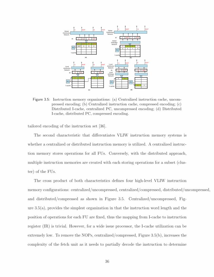
EDCNOP
NOPBNOPA
PC
NOPBNOPA
I-cache
IR
Global
Distribution
Network
(a)
GFED
CBAX
PC
BA
I-cache
IR
(b)
Global
Shift/align
Network
Global
Distribution
Network
A NOP B NOPA NOP B NOP
Local
distribution
Network
NOPA NOPB
NOPA NOPB
PC
IR
I-cache
(c)
Local
distribution
Network
A B
X A’
YB’
PC
IR
I-cache
PC
Local
shift/align
Network
A BNOP NOP
(d)
A NOP B NOP
NOP NOP
NOP NOP
Figure 3.5: Instruction memory organizations: (a) Centralized instruction cache, uncom-pressed encoding; (b) Centralized instruction cache, compressed encoding; (c)Distributed I-cache, centralized PC, uncompressed encoding; (d) DistributedI-cache, distributed PC, compressed encoding.
tailored encoding of the instruction set [36].
The second characteristic that differentiates VLIW instruction memory systems is
whether a centralized or distributed instruction memory is utilized. A centralized instruc-
tion memory stores operations for all FUs. Conversely, with the distributed approach,
multiple instruction memories are created with each storing operations for a subset (clus-
ter) of the FUs.
The cross product of both characteristics defines four high-level VLIW instruction
memory configurations: centralized/uncompressed, centralized/compressed, distributed/uncompressed,
and distributed/compressed as shown in Figure 3.5. Centralized/uncompressed, Fig-
ure 3.5(a), provides the simplest organization in that the instruction word length and the
position of operations for each FU are fixed, thus the mapping from I-cache to instruction
register (IR) is trivial. However, for a wide issue processor, the I-cache utilization can be
extremely low. To remove the NOPs, centralized/compressed, Figure 3.5(b), increases the
complexity of the fetch unit as it needs to partially decode the instruction to determine
36

the boundary of the instruction word and correctly expand the compressed instruction
into the IR.
The scalability problem of centralized I-caches can be overcome by utilizing distributed
caches. With a distributed approach in a multicluster processor, each cluster has its own
I-cache to supply instructions. Assuming each cluster is homogeneous, all operations are
the same size, and no compression, all clusters execute the same cache entry each cycle.
Thus, the distributed/uncompressed (Figure 3.5(c)) can utilize a common PC to index
into each I-cache. The use of a common PC relies on each cluster having a constant
instruction rate during the execution. Most previous research on distributed instruction
memories falls into this category as they rely on a single PC or multiple identical PCs to
index the memories when a single program is executed. Since XIMD has no I-cache, a more
sophisticated compiler may be able to remove this restriction [78]. Another approach, the
Silo cache [14], partitions the instruction cache into silos, where each silo holds operations
for a particular set of FUs. All silos are indexed by a single PC. Although instructions
must be uncompressed, multiple instructions can coexist at the same address across silos.
The proposed DVLIW architecture falls into the Distributed/compressed category as
illustrated in Figure 3.5(d). To support compressed encodings with a distributed I-cache,
the PC must also be distributed as instruction sizes for each cluster must be allowed to
vary. All the clusters fetch independently from different PCs and compute their own next
PCs. The DVLIW architecture and its operation are discussed in detail in the following
sections.
37

3.2 Voltron: Multicore Extension to Exploit Hybrid
Parallelism
Parallelization opportunities can also be created by slicing program regions into mul-
tiple communicating sequential subgraphs or fine-grain threads. Fine-grain TLP allows
concurrent execution of instructions as well as the overlapping of memory latencies. Com-
pared to traditional coarse-grain threads, Fine-grain threads contain frequent register
communications among them. The execution of fine-grain threads are asynchronous, each
thread can slip with respect to each other. Concurrent execution of fine-grain threads
provides the benefit of coarse-grain out-of-order execution on in-order cores.
To effectively deal with mapping general-purpose applications onto multicore systems,
new architectural support is needed that is capable of efficiently exploiting fine granular-
ities of parallelism. These hybrid forms of parallelism include ILP, memory parallelism,
and fine-grain TLP. To accomplish this goal, this section proposes a multicore architec-
ture, referred to as Voltron. Voltron extends conventional multicore systems by providing
architectural support to configure the organization of the resources to best exploit the
hybrid forms of parallelism that are present in an application. There are two primary
operation modes: coupled and decoupled. The coupled mode supports the functionality
of DVLIW discussed previously. In coupled mode, each core operates in lock-step with all
other cores forming a wide-issue VLIW processor. Through compiler orchestrated con-
trol flow, coupled mode exploits ILP across multiple instruction streams that collectively
function as a single-threaded stream executed by a VLIW processor. Although cores
fetch independently, they execute instructions in the same logical location each cycle,
and branch to the same logical target. In decoupled mode, all cores operate indepen-
dently on separate fine-grain threads. The compiler slices an application into multiple,
38

communicating subgraphs that are initiated using a lightweight thread spawn mechanism
that operates in the same program context. Decoupled mode offers the opportunity to
efficiently exploit TLP and memory parallelism using fine-grain, communicating threads.
There are several key architectural features of Voltron that enable efficient execution
and flexible configurability. First, a lightweight operand network provides fast inter-
processor communication in both execution modes. The operand network provides a
direct path for cores to communicate register values without using the memory. Second,
a compiler-orchestrated distributed branch architecture enables multiple cores to exe-
cute multi-basic block code regions in a completely decentralized manner. This enables
single-threaded, branch-intensive applications to be executed without excessive thread
spawning and synchronization barriers. Finally, flexible memory synchronization sup-
port is provided for efficient handling of explicit memory communication and ambiguous
memory dependences.
3.2.1 Voltron Architecture Overview
Figure 3.6(a) shows an overall diagram of a four-core Voltron system. The four cores
are organized in a two-dimensional mesh. Each core is a single-cluster VLIW processor
with extensions to communicate with neighboring cores. Cores have private L1 instruction
and coherent data caches, and all four cores share a banked L2 cache and main memory.
The cores access a unified memory space; the coherence of caches is handled by a bus-based
snooping protocol. The Voltron architecture does not limit the way in which coherence
between cores is maintained; any hardware or software coherence protocol will suffice. A
scalar operand network connects the cores in a grid. The network includes two sets of
wires between each pair of adjacent cores to allow simultaneous communication in both
directions. The topology of the cores and the latency of the network is exposed to the
39

GPR FPR PR BTR
Register Files
FUMemFU
. . .
To northTo west
L1Instruction Cache
L1 Data Cachewith Transactional Memory Support
From Banked L2 To/From Banked L2
Instruction Fetch/Decode
CommFU
(a) (b) (c)
Core
Comm FU
Routing
Logic
To west To north
To Register File
Direct
Mode B
ypass
Direct
Mode B
ypass
Send Q
ueue
Rece
ive Q
ueue
Core 0 Core 1
Core 2 Core 3
Banked L2 Cache
Banked L2 Cache
Stall Bus
Figure 3.6: Block diagram of the Voltron architecture: (a) 4-core system connected in amesh topology, (b) Datapath for a single core, and (c) Details of the inter-corecommunication unit.
compiler, which partitions the work of a single-threaded program across multiple cores
and orchestrates the execution and communication of the cores. A 1-bit bus connecting all
4 cores propagates stall signals in the coupled execution mode (discussed in section 3.2.3).
Figure 3.6(b) shows the datapath architecture of each core, which is very similar to
that of a conventional VLIW processor. Each core has a complete pipeline, including
an L1 instruction and data cache, an instruction fetch and decode unit, register files,
and function units (FUs). The execution order of instructions within a core is statically
scheduled by the compiler. A Voltron core differs from a conventional VLIW processor
in that, in addition to other normal functional units such as an integer ALU, a floating-
point ALU, and memory units, each core has a communication unit (CU). The CU can
communicate with other cores in the processor through the operand network by executing
special communication instructions.
40

3.2.2 Dual-mode Scalar Operand Network
The dual-mode scalar operand network supports two ways to pass register values
between cores to efficiently exploit different types of parallelism. Although both ILP
and fine-grain TLP execution need low latency communication between cores, they have
different requirements for the network. ILP execution performance is very sensitive to the
communication latency, thus it is important to make the latency as low as possible for ILP
execution. On the other hand, the execution of multiple fine-grain threads are decoupled,
thus fine-grain threads are less sensitive to the latency. However, fine-grain threads require
asynchronous communication between cores; therefore, queue structures must be used to
buffer values. The Voltron scalar operand network supports two modes to meet the
requirement of ILP and fine-grain TLP execution: a direct mode with very low latency
(1 cycle per hop) but requires both parties of the communication to be synchronized, and
a queue mode with higher latency (2 cycles + 1 cycle per hop) but allows asynchronous
communication.
The scalar operand network in a Voltron processor consists of the communication
components in every core and the links between cores. Figure 3.6(c) shows the detail of
the CU in a Voltron core. A core performs communication with another core through the
scalar operand network by issuing special instructions to the communication unit. The
operation of the CU depends on the communication mode.
Direct mode. The direct mode communication supports the ILP execution across
multiple cores. It allows two adjacent cores to communicate a register value in one cycle.
The same PUT/GET instructions introduced in section 3.1.2 are used for direct mode
communication.
The direct mode bypass wires in Figure 3.6(c) allow the communication unit to ac-
cess the inter-core connections directly. Thus, the communication latency between two
41

adjacent cores under direct mode is very low, only requiring one cycle to communicate
a register value between neighboring cores. This mode of communication requires the
cores to execute in lock-step to guarantee PUT/GET operations are simultaneously exe-
cuted. If a core needs to communicate with a non-adjacent core, a sequence of PUT and
GET pairs are inserted by the compiler to move the data to the final destination through
multiple hops.
Queue mode. Queue mode allows decoupled communication between cores. Under
this mode, the core that produces a register value does not need to remain synchronized
with the core that consumes the value. The send queue, receive queue, and the router in
Figure 3.6(c) are used to support this mode of communication. Two operations are added
to the ISA to support queue mode communication: SEND and RECV. A SEND operation
takes two operands, a source register number and a target core identifier. When a SEND
operation is executed, it reads the value in the source register and writes a message to
the send queue in that core. The message contains the value from the sender core as
well as the target core identifier. A RECV operation analogously takes two operands,
a destination register number and a sender core identifier. When a RECV operation is
executed, it looks for the message from the specified sender in the receive queue, and
writes the data to the destination register if such a message is found. It stalls the core
if such a message is not found. The receive queue uses a CAM structure to support fast
sender identifier lookup.
The router gets items from the send queue and routes them to the target core through
one or more hops. In queue mode, SEND and RECV operations do not need to be issued
in the same cycle. Data will wait in the receive queue until the RECV is executed, and the
receiver core will stall when a RECV is executed and the data is not available. Only one
pair of SEND/RECV operations is required to communicate between any pair of cores;
42

PBR r10 = BB10
CMP p1 = (i>100)?
BR r10 if p1
PBR r10 = BB10
CMP p1 = (i>100)?
BCAST p1
BR r10 if p1
PBR r11 = BB10
GET p2
BR r11 if p2
PBR r10 = BB10
CMP p1 = (i>100)?
BR r10 if p1
PBR r11 = BB10
CMP p2 = (i>100)?
BR r11 if p2
(a) (b) (c)
core 0 core 1 core 0 core 1
Figure 3.7: Execution of a distributed branch: (a) Original unbundled branch in HPL-PD, (b) Branch with predicate broadcast, and (c) Branch with the conditioncomputation replicated.
the router will find a path from the sender to the receiver. The latency of communication
between cores in the queued mode is 2 + number of hops: it takes one cycle to write the
value to the send queue, one cycle per hop to move the data, and one cycle to read data
from the receive queue. The operand network operating in queue mode is similar to the
RAW scalar operand network [72].
The two modes of communication provide a latency/flexibility trade-off. The compiler
can examine the characteristics of an application to utilize direct mode when communi-
cation latency is critical and queue mode when non-deterministic latencies caused by
frequent cache misses dominate.
3.2.3 Voltron Execution Modes
Voltron supports two execution modes that are customized for the form of parallelism
that is being exploited: coupled and decoupled. Coupled efficiently exploits ILP using
the direct mode operand network, while decoupled exploits LLP and fine-grain TLP using
the queue mode operand network.
Coupled mode. In coupled mode, all cores execute in lock-step, collectively behaving
like a wide-issue multicluster VLIW machine. The cores pass register values to each
other using the direct communication mode. The compiler is responsible for partitioning
computation, scheduling the instructions, and orchestrating the communication between
cores. In this mode, each core maintains its own control flow, but collectively emulate
43

a multicluster VLIW [81]. The branch mechanism in Voltron is based on the unbundled
branch in the HPL-PD ISA [32]. In HPL-PD, the portions of each branch are specified
separately: a prepare-to-branch (PBR) operation specifies the branch target address, a
comparison (CMP) operation computes the branch condition, and a branch (BR) transfers
the control flow of the program based on the target address and the branch condition, as
illustrated in Figure 3.7(a).
Figure 3.7(b) illustrates the branch mechanism in Voltron coupled mode. To synchro-
nize the control flow in all cores, each core specifies its own branch target using separate
PBR operations. The branch target represents the same logical basic block, but different
physical block as the instructions for each core are located in different memory spaces.
The branch condition is computed in one core and broadcast to all the other cores using
a BCAST operation. Other cores receive the branch condition using a GET operation to
determine if the branch is taken or fall through. (Note, the branch condition can alterna-
tively be replicated on all cores as shown in Figure 3.7(c)). BR operations are replicated
across all cores and scheduled to execute in the same cycle. When the BR operations are
executed, every core branches to its own branch target (same logical target) keeping all
cores synchronized. In essence, separate instruction streams are executed on each core,
but these streams collectively function as a single logical stream on a conventional VLIW
processor.
If one core stalls due to cache misses, all the cores must stall to keep synchronized. The
1-bit stall bus is used to propagate this stall signal to all 4 cores. For a multicore system
with more than 4 cores, propagating the stall signal to all cores within one cycle may
not be realistic. We solve this problem using the observation that coupling more than 4
cores is rare as it only makes sense when there are extremely high levels of ILP. Therefore,
cores are broken down into groups of 4 and coupled mode execution is restricted to each
44

A
B C
D
E
F
G
I
(a) (b) (d)(c)
time timecore0 core1
B.1B.0
D.0
A.0 A.0A.1STALL
E.0
D.1
F.0
STALL
F.1
A.0 A.1
C.1
D.0
C.0
D.1
E.1
G.1G.0
I.0 I.0
F.0 F.1
I.0 I.0
br. cond.
br. cond.
br. cond.
br. cond.
br. cond.
br. cond.
br. cond.
br. cond.
core1
A.0A.0A.1
STALL
core0
B
D.0
D.1STALL
A.0
A.1
C
D.1
D.0 D.1
E
F.0F.1
spawn
bcast
br
recvebr
jump
br
br’
if (condition) sleepbr
recvebr
bcast
br
jump
G
I.1
I.0
F.0
I.0F.1
I.1
jump
bcastbr recv
ebr
recv
ebr
bcastbr
br
br’
jump
br
br’
spawn
br. cond.
br. cond.
br. cond.
br. cond.
core0 core1
A.0
B
D.0
E
F.0
I.0
A.1
C
D.1
F.1
G
I.1
Figure 3.8: Code execution under different modes. (a) Control flow graph of a codesegment. (b) Execution of the code segment under coupled mode. (c) Controlflow graph of fine-grain threads extracted for decoupled mode. (d) Executionof the code segment under decoupled mode.
group. Of course, decoupled mode can happen within the groups or across groups when
exploiting LLP and fine-grain TLP.
To illustrate coupled mode execution, Figure 3.8(a) shows the control flow graph
(CFG) of an abstract code segment. Each node in the graph represents a basic block in
the single-thread program. Figure 3.8(b) illustrates the code segment executing in coupled
mode on a two-core system. The compiler partitions each block into two blocks, one for
each core, using a multicluster partitioning algorithm [21]. For example, the operations
in block A are divided into A.0 and A.1 to execute on core0 and core1, respectively. The
schedule lengths of any given block are the same across all the cores; if they differ, the
compiler inserts NO OPs to ensure they match. All cores execute in lock-step and com-
municate through PUT and GET operations (not shown in the figure). When core0 stalls
due to a cache miss in A.0, both cores have to stall to keep the execution synchronized.
Similarly, when core1 stalls in D.1, both cores stall. Every branch in the original code is
45
replicated to all cores. For conditional branches, such as the branch at the end of block
A, the branch condition is computed in one core and broadcast to the others.
The most important benefit of coupled mode is the low communication latency of
using the operand network in direct mode. Coupled mode can handle frequent inter-core
communication without increasing the schedule length by a large amount. The drawback
is its lockstep execution. If one core stalls, all cores stall. The stalling core prevents
other cores from making any progress even if parallelism exists. Coupled execution mode
is ideal for code with high ILP, predictable cache misses, and complicated data/memory
dependences, which require a large amount of inter-core communication and can benefit
from the low communication latency.
Decoupled Mode. The second mode of execution is decoupled where each core
independently executes its own thread. As with a conventional multicore system, stalls
on one core do not affect other cores. However, fast communication of register values
through the scalar operand network allows Voltron to exploit a much finer grain of TLP
than conventional multicore systems, which communicate through memory. The compiler
automatically extracts fine-grain threads from a single-thread program using mechanisms
described in Chapter 4. Multiple threads execute independently on multiple cores and
communicate through the scalar operand network. The network operates in queue mode
for decoupled execution.
A core initiates the execution of a fine-grain thread on another core by executing a
SPAWN operation, which sends the starting instruction address of the fine-grain thread to
be executed to the target core. The target core listens to the receive queue when it is idle.
Upon the arrival of the instruction address, it moves the value to its program counter (PC)
and starts executing from that address. All fine-grain threads share the same memory
space and stack frame, thus there is no setup for a separate context required. The live-in
46
values for the fine-grain thread are received through the operand network during execution
or are loaded from memory. When the execution of a fine-grain thread finishes, it executes
a SLEEP operation, and the core listens to the queue for the starting address of the next
fine-grain thread. The register values in a core remain unchanged after a fine-grain thread
terminates. The next fine-grain thread to execute on that core can use the values in the
register file as live-in values.
Multiple fine-grain threads can collectively and efficiently execute the same multi-block
region of the original single-thread program. In this case, the branch operations in the
original code are replicated in all the fine-grain threads. The branch condition for each
branch can be computed in one thread and broadcast to others, similar to the coupled
mode. The differences here are that the branch conditions are broadcast using queue
mode, and that the branches do not need to be scheduled in the same cycle anymore. In
decoupled mode, the computation of the branch conditions can also be replicated to other
cores to save communication and reduce receive stalls. The compiler uses a heuristic to
decide if the branch condition should be broadcast or computed locally for each branch.
The right hand side of Figure 3.8 illustrates the differences in partitioning and exe-
cution in decoupled mode. In decoupled mode, the compiler divides the application into
fine-grain threads. Figure 3.8(c) depicts the threads extracted from the CFG shown in
Figure 3.8(a). The first inner loop, which includes blocks A, B, C, and D, is partitioned
between the cores. Block A is divided into two parts, A.0 and A.1 (similar to coupled
mode), while all operations in block B are assigned to core0 and all operations in block
C to core1. Block D is split analogously to block A.
Figure 3.8(d) shows the execution of these fine-grain threads in decoupled mode. Be-
fore core0 enters the first inner loop, a SPAWN operation is executed, which sends the
start address of A.1 to core1. The execution of blocks A.0 and A.1 are independent;
47
stalls that occur during A.0 do not affect A.1. The cores communicate register values
using SEND and RECV operations (not shown in the figure). A.1 computes the branch
condition for the block and broadcasts it to core0 using the scalar operand network in
queue mode. After receiving the branch condition from core1, core0 branches to block
B. Since the compiler assigned all operations in block B to core0, core1 directly jumps
to block D. The branch as well as the branch condition computation is replicated across
both cores in block D, thus broadcast and receive are not needed for this block. After
two iterations, the execution exits the first inner loop, and the fine-grain thread in core1
finishes, executing a SLEEP operation. Block E in core0 will spawn another thread for
the second inner loop to execute on core1. In this example, core0 behaves as the master,
spawning jobs to core 1. This is the general strategy used by our compiler.
The most important benefit of decoupled mode is its tolerance to unexpected stalls,
such as cache misses. Each core operates in its own stall domain and thus stalls inde-
pendently. Memory parallelism can be exploited by overlapping cache misses on multiple
cores or allowing other cores to make progress on their own thread as long as dependences
are not violated. The fine-grain threads in Voltron provides a form of macro out-of-
order execution across the cores, without the hardware and complexity of a wide-issue
superscalar processor.
Hybrid execution modes are also possible in Voltron where the cores can be partitioned
into several synchronization domains. Within each domain, the cores can execute either
in coupled mode or in decoupled mode, allowing some domains to exploit ILP while
others exploit TLP. This feature provides greater adaptability to the available application
parallelism.
Switching Between Modes. Voltron supports fast mode switching by adding a new
instruction MODE SWITCH. MODE SWITCH takes one literal operand specifying the
48

new mode. When switching from coupled mode to decoupled mode, the compiler inserts
MODE SWITCH instructions in all cores and makes sure they are issued in the same
cycle (similar to the distributed branch discussed previously). To switch from decoupled
to coupled mode, the compiler inserts MODE SWITCH instructions before the coupled
code region in all cores. The MODE SWITCH behaves as a barrier, so all cores wait until
the last core reaches the switch to start synchronized execution. Note that the values in
the register files are unchanged during the mode switch. This behavior facilitates running
a single application in different modes and transparently switching between modes for
different program regions.
3.2.4 Memory Dependence Synchronization
Up to this point in the discussion, communication of register values between cores has
only been discussed. In coupled mode, the cores execute in lockstep, thus the compiler
scheduler must simply schedule the consumer of a register value after the producer by
the appropriate number of cycles. PUT and GET instructions accomplish the actual
transfer of data across the cores. In decoupled mode, the compiler inserts SEND and
RECV operations after and before the communicating operations. If the value does not
arrive when the RECV operation is executed, the receiving core stalls until the data
arrives. Thus, the needed synchronization is handled naturally by the SEND and RECV
operations.
The cores can also communicate values through memory. Stores and loads that can-
not be disambiguated by the compiler must execute in program order to ensure correct
execution. In coupled mode execution, this simply requires the compiler to enforce both
intra-core and inter-core memory dependences when the schedule is created. As long as
dependent memory are executed in subsequent cycles, the hardware will ensure the correct
49

data is obtained using the coherence mechanism.
In decoupled mode, the memory dependence problem is more difficult. We take
the simple approach of just using the operand network to enforce the dependence. A
SEND/RECV pair are used to send a dummy register value from the source of the de-
pendence to the sink. Memory synchronization using SEND/RECV has two drawbacks.
First, the SEND/RECV pair occupies the CUs and bandwidth without passing any use-
ful value, which could delay other useful communication and consumes energy. Second,
the SEND/RECV goes through message queues and routing logic, incurring a minimum
latency of three cycles. Through our experimental evaluation, these drawbacks are not
that serious. The compiler can perform sophisticated analysis to remove as many false
dependences as possible [53]. Further, to reduce synchronization stalls, its important for
the compiler to place dependent memory operations on the same core. Thus, in practice,
the number of inter-core memory dependences is not large.
3.3 Multicore Extension for Speculative LLP
This work proposes mechanisms to exploit statistical loop level parallelism with min-
imal hardware cost. The spirit is to expose several generic architecture features to the
compiler and let compiler to handle speculative execution whenever possible. Hardware
is only used when the software alternative is too costly, for example, to detect dynamic
memory dependence conflicts. A number of works [27, 67, 68] have proposed executing
speculative threads in environments where much of the burden is given to hardware and
requires complex hardware to fully support thread level speculation. By employing a hard-
ware/software approach, our technique has a lower hardware cost than other hardware
centric TLS techniques while still achieve comparable performance gains.
50

3.3.1 Requirements
Efficient exploitation of statistical loop-level parallelism requires extensions to tra-
ditional chip-multiprocessors to facilitate speculative parallel execution. The required
features can be supported using software or hardware mechanisms. However, software
implementations of these features usually have a large performance impact. In order to
make the parallelization of small and medium size loops profitable, architectural support
for the following features is desired.
Detection of cross-core memory dependences. If two memory operations (load
or store) access the same memory location, and at least one of them is a store, a memory
dependence exists between those two operations. Loops are parallelized if the profile
indicates that no cross-iteration memory dependences exists or they are very rare. At run
time, accesses to the same memory location from different cores must be detected, and a
recovery action must be initiated if a memory dependence is violated.
Undo/rollback. If a memory dependence violation is detected, the executions on
cores that execute higher iterations need to abort and restart. The architectural state
on the aborted core, including registers and memory content, must be rolled back to the
state before the speculative execution started. Our compiler technique provides a simple
way to roll back the necessary registers, so hardware support is not necessary to restore
register values.
Light-weight thread spawning. To exploit statistical loop level parallelism, multi-
ple threads, each thread consists one or more iterations of the loop, executes speculatively
in parallel in multiple cores. Low latency mechanism to spawn threads are essential for
the performance of statistical DOALL loops, especially for those with small loop bodies
and low trip counts.
51

Core 0 Core 1
Core 2 Core 3
Banked L2 Cache
Banked L2 Cache
(a) (b)
GPR FPR PR BTR
Register Files
FUMemFU
. . .
To northTo west
L1Instruction Cache
L1Data Cache with
Transactional Memory Support
From Banked L2 To/From Banked L2
Instruction Fetch/Decode
CommFU
(b)
GPR FPR PR BTR
Register Files
FUMemFU
. . .
To northTo west
L1Instruction Cache
L1Data Cache with
Transactional Memory Support
From Banked L2 To/From Banked L2
Instruction Fetch/Decode
CommFU
Figure 3.9: Block diagram of the target architecture: (a) 4-core system connected in amesh topology, (b) Datapath for a single core
Inter-core scalar communication. Before the parallel execution of a loop, several
scalar register values are passed to all cores to initiate the live-in values. Similarly, after
the parallel execution, live-out scalar values of the loop are passed from all cores to the
users of the live-out scalars. A low latency mechanism to pass scalar values between cores,
either through memory or a scalar operand network [72], is essential.
Instruction ordering between cores. During the speculative execution of loops,
certain actions must happen in order. More specifically, cores must commit their execution
in order. After commit, the changes made by a core cannot be undone, so the core
executing earlier iterations of the loop must be committed before cores executing later
iterations. This ordering is required for every loop, so efficient ways to enforce ordering
among cores are needed.
52
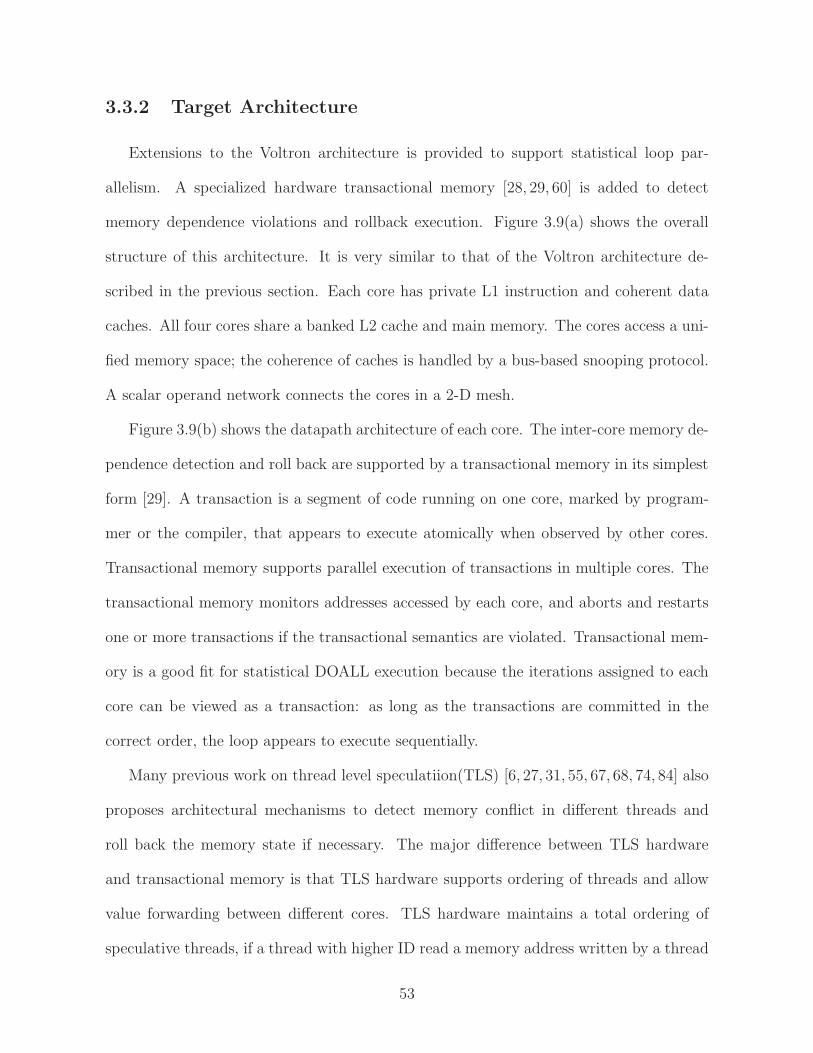
3.3.2 Target Architecture
Extensions to the Voltron architecture is provided to support statistical loop par-
allelism. A specialized hardware transactional memory [28, 29, 60] is added to detect
memory dependence violations and rollback execution. Figure 3.9(a) shows the overall
structure of this architecture. It is very similar to that of the Voltron architecture de-
scribed in the previous section. Each core has private L1 instruction and coherent data
caches. All four cores share a banked L2 cache and main memory. The cores access a uni-
fied memory space; the coherence of caches is handled by a bus-based snooping protocol.
A scalar operand network connects the cores in a 2-D mesh.
Figure 3.9(b) shows the datapath architecture of each core. The inter-core memory de-
pendence detection and roll back are supported by a transactional memory in its simplest
form [29]. A transaction is a segment of code running on one core, marked by program-
mer or the compiler, that appears to execute atomically when observed by other cores.
Transactional memory supports parallel execution of transactions in multiple cores. The
transactional memory monitors addresses accessed by each core, and aborts and restarts
one or more transactions if the transactional semantics are violated. Transactional mem-
ory is a good fit for statistical DOALL execution because the iterations assigned to each
core can be viewed as a transaction: as long as the transactions are committed in the
correct order, the loop appears to execute sequentially.
Many previous work on thread level speculatiion(TLS) [6, 27, 31, 55, 67, 68, 74, 84] also
proposes architectural mechanisms to detect memory conflict in different threads and
roll back the memory state if necessary. The major difference between TLS hardware
and transactional memory is that TLS hardware supports ordering of threads and allow
value forwarding between different cores. TLS hardware maintains a total ordering of
speculative threads, if a thread with higher ID read a memory address written by a thread
53

with lower ID, the hardware forwards the value to the higher thread. Data forwarding can
avoid some unnecessary aborts and potentially improve the performance. The drawback
of TLS hardware is that it is usually very complex and costly in terms of hardware area.
On the other hand, transactions in transactional memory are usually unordered. User
has to enforce the ordering of commit in software if necessary. Since there is no notion of
ordering between thread, the hardware do not forward data between transactions. The
hardware for transactional memory can be fairly simple. Transactional memory can also
be implemented in software, obviously with some performance overhead.
Since this work targets loop with no or very few cross iteration dependence. The need
for data forwarding between cores should be minimal. We choose transactional memory
for its lower hardware cost. Ordering of threads is still required. We can simply assign
an ID for every transaction, and relies on software to enforced the commit order.
Many transactional memory designs have been proposed in the literature [5, 28, 29,
47, 49, 80]. A taxonomy introduced in [49] classifies transactional memory systems based
on their version management and conflict detection mechanisms.
Version management handles the simultaneous storage of both new data (to be visible
if the transaction commits) and old data (retained if the transaction aborts). An eager
version management allows a store to put the new data in place (the target memory ad-
dress), and save the old data on the side (e.g., in a log). An lazy version management
keeps in old data in place and store the new data on the side. An eager version manage-
ment allows fast commit, because all the new data are already in place, but transaction
abort can be costly because it involves restore the old data from another place. On the
other hand, the transaction commit is slow using lazy version management but aborts can
be fast. Since we target statistical DOALL loops with very few cross iteration memory
dependences, we expect most transactions to commit without abort. An eager version
54

management is a better choice for our system.
Conflict detection detects memory conflicts between transactions. If a memory ad-
dress is written in one transaction, and the same address is read or written in another
transaction, there is a memory conflict. Conflict detection can be eager or lazy. Eager
detection detects conflicting memory access immediately, and lazy detection detects the
conflicts later, usually when a transaction tries to commit. Eager detection can identify
a conflict earlier, prevent unnecessary computation that will be aborted later, and restart
the transaction earlier. Eager detection can utilize existing coherence hardware to detect
conflicts immediately, thus the hardware overhead is modest. This work assumes a eager
conflict detection policy for the transaction memory.
Our implementation of transactional memory is similar to LogTM-SE [80]. It supports
eager version management and eager conflict detection. We extend the transactional
memory in three major aspects to facilitate speculative DOALL loop execution.
First, a transaction ID is added for each transaction. For speculative DOALL loops,
we always want to abort the transaction running higher iterations when a memory conflict
is detected, We extend the transactional memory hardware with a transaction ID for the
ordering of transactions. When a conflict is detected, the transaction with higher ID will
be aborted. The transaction ID is specified by software when a transaction begins.
Second, a new ABORT instruction is inserted in the ISA. Unlike other other trans-
actional memory implementations, where transaction abort happens implicitly when a
conflict is detected, the ABORT instruction allows a core to explicitly abort transactions
on other cores. It takes an core ID as source operand and abort any pending transactions
on that core. This is needed for uncounted loops because in while loops, if one iteration
exits the loop, it needs to stop the execution on all higher cores.
Third, an abort handler is added for each transaction. An abort handler contains an
55

Requirement Hardware Support Compiler Support
Detection ofMemory Conflict
Transactional memory. N/A
Rollback For memory: transactional mem-ory.
For memory: N/A
For register: jump to abort handler. For register: implement the aborthandler to roll back registers.
Fast Spawning Scalar operand network. Insert code to send PC and live-inscalar values.
Scalar Commu-nication
Scalar operand network. Insert SEND/RECV to communi-cate scalar values.
InstructionOrdering
Scalar operand network. Insert dummy SEND/RECV toguarantee instruction ordering.
Table 3.1: Hardware and software support to meet requirement for statistical loop levelparallelism.
code address that a transaction jumps to when an abort happens. The abort handler
allows the compiler to insert recovery code when transaction aborts. It enables several
code transformations to expose more speculative LLP. The software specifies the abort
handler when the transaction begins.
Two new instructions, XBEGIN and XCOMMIT, are used to mark the beginning
and end of a transaction, XBEGIN takes two operands, an transaction ID, and a abort
handler. XCOMMIT tries to commit a transaction. If the commit is successful, all
speculative stores in the transaction will become permanent; if the commit fails, it will
restart the transaction from the abort handler.
The roll back of register files is managed by compiler; this will be discussed later, in
Chapter 5.
The proposed architecture, together with appropriate compiler support, meets all five
requirements listed in section 3.3.1. Table 3.1 shows how the burden of meeting those re-
quirements are divided between hardware and compiler. A low-cost transactional memory
56

is used to detect memory dependence violation and rollback memory state when neces-
sary. For register states, the hardware transfer the control to the address specified by
abort handler when memory dependence violation is detected, the compiler is respon-
sible for implementing the abort handler and recover the necessary register states for
re-execution. The scalar operand network in the hardware is used to support fast thread
spawning, low latency inter-core scalar communication, and enforce interior instruction
ordering. The compiler need to insert code to send PC and live-in scalar values to spawn
a thread, insert SEND/RECV instruction to communication scalar values between cores,
and insert SEND/RECV that communicate dummy values to enforce ordering of instruc-
tions in different cores.
The architecture described above supports efficient exploitation of ILP, fine-grain TLP
and statistical LLP. The compiler is in charge of selecting the best parallelism to exploit
and generate appropriate code for each core. The compiler algorithms are described in
the next chapter.
3.4 Related Work
A large body of prior work exists in the area of exploiting distributed parallelism.
This section discuss the relation of the proposed ILP, fine-grain TLP and statistical LLP
architecture with previous works:
Distributed VLIW Architecture Models. The proposed architecture exploit ILP
by emulating a multicluster VLIW. It is built directly upon prior multicluster VLIW
processor designs, including Multiflow TRACE [13], XIMD [78], and MultiVLIW [64].
The clustered register file was first introduced in the Multiflow processor to facilitate
wide-issue design. MultiVLIW has expanded this work by focusing on alternative archi-
57

tecture/compiler strategies for designing scalable distributed data memory subsystems.
Interleaved data caches [24] or compiler-managed L0 buffers [25] independently supply
memory data to each cluster. The proposed architecture extends these works in an or-
thogonal direction by focusing on fully distributing the control path and applying the idea
the a multicore context.
Recently, reconfigurate multiple cores to form a larger CPU to exploit ILP has drawn
much attention. TRIPS [65] exploits distributed ILP by statically placing instructions
on different execution nodes, and the execution model if similar to that in dataflow ma-
chines. When an instruction completes, it routes the output to other execution nodes, and
dependent instructions are triggered. Core fusion [30] introduced a reconfigurable CMP
architecture that allows simple out-of-order CMP cores to dynamically fuse into larger
out-of-order processor. Mechanisms for collective fetch, rename, execution, cache access
and commit are studied. Core fusion steers the instructions to different cores at runtime,
thus it doesn’t need compilers to partition the code, which provides better software com-
patibility. On the other hand, DVLIW pre-partition the code onto different cores, thus no
complex dynamic steering logic is needed. DVLIW is also more power efficient because
no energy is spent on steering instruction at runtime.
Architectural Support for Fine-grain TLP Several architectures have been pro-
posed to exploit fine-grain parallelism on distributed, multicore systems. RAW [71] is the
most similar to this work and is a general-purpose architecture that supports instruction,
data and thread-level parallelism. In RAW, a set of single-issue cores are organized in a
two dimensional grid of identical tiles. Scalar operand networks are used to route inter-
mediate register values between tiles [72]. Both the execution on tiles and the routing
on the network are software controlled by the compiler. A dynamic routing network also
exists to route memory values. The central difference between Voltron and RAW is the
58

dual execution mode capability and its associated effects on the architecture. The two
execution modes allow Voltron to exploit fine-grain TLP like RAW as well as VLIW-style
ILP.
The M-Machine [22] is a multiprocessor system that focuses on exploiting fine-grain
parallelism. One unique feature of the M-Machine is the direct inter-processor communi-
cation channels. Processors communicate intermediate results by directly writing values
into the register files of other processors. The M-Machine can exploit both ILP and
TLP using these mechanisms. Voltron assumes a more traditional organization of the
individual cores and layers on top of that the dual-mode operand network. Further, the
lack of communication queues in the M-Machine limits the amount of decoupling between
threads. The M-Machine also requires explicit synchronization between processors to ex-
ploit ILP, while coupled mode in Voltron allows implicit synchronization for lower-latency
communication. The J-Machine [51] is a multicomputer that supports fast message pass-
ing and synchronization between nodes. It showed that fine-grain parallel computing is
feasible on multiprocessors and serves as strong motivation for this work.
Distributed processing has also been investigated in the context of superscalar proces-
sors, including Multiscalar [67], Instruction Level Distributed Processing (ILDP) [33], and
TRIPS [65]. In the Multiscalar processor, a single program is divided into a collection of
tasks by a combination of software and hardware. The tasks are distributed to multiple
parallel processing units at run time and execute speculatively. Recovery mechanisms are
provided if the speculation is wrong. The ILDP architecture contains a unified instruction
fetch and decode; the front-end distributes strands of dependent operations to multiple
distributed PEs. An interconnection network connects the PEs and routes register values.
TRIPS supports explicit data graph execution, which is similar to dataflow execution, to
exploit ILP from single thread programs. The execution units on TRIPS are hyperblocks.
59

At runtime, the cores fetch blocks from memory, execute them and commit the results to
architectural state. Decoupled execution in Voltron is different from these architectures
in that program execution is fully orchestrated by the compiler. The compiler partitions
the code, assigns code to cores, schedules the execution within each core and inserts com-
munication between cores. The compiler orchestrated execution allows the hardware to
be simple and efficient.
Architectural Support for Thread Level Speculation. Previous work on Thread-
Level Speculation (TLS) [55] and Thread-Level Data Speculation (TLDS) [68, 69] proposes
the execution of threads with architectural support. Those works propose programmer
identification of regions of code that can form transactions, and also discuss specula-
tion on loops. Oplinger et. al [55] in particular identify different styles of loops. This
work extends those ideas with compiler techniques for loop identification, selection, and
automatic code generation.
Multiscalar architectures [67] also support thread-level speculation, and prior work [76]
has studied graph partitioning algorithms to extract multiple threads; however, this does
not eliminate unnecessary dependences in the same way this work does.
One unique feature of the Voltron architecture is that it supports all three types
of parallelism, ILP, fine-grain TLP and statistical LLP in a single architecture. The
architecture can be dynamically reconfigured to exploit the best ILP in the code.
60

CHAPTER 4
Compiler Techniques for Extracting Fine-grain
Parallelism
The execution of programs on the Voltron architecture is orchestrated by the com-
piler. Good compiler techniques are essential to application performance. This work took
advantage of advanced analysis, optimization, and transformation techniques and aug-
mented them with novel algorithms to exploit different types of parallelism. This chapter
discusses the compiler technique to exploit fine-grain parallelisms include ILP and fine-
grain TLP. Compiler techniques to exploit speculative LLP will be discussed in the next
Chapter.
4.1 Compiling for ILP execution
To exploit ILP on the Voltron architecture proposed in Chapter 3, the compiler must
partition the instructions across the cores, replicate the control flow to all cores, and
insert communication instructions to transfer values besides the conventional compiler
tasks such as scheduling and register allocation. Figure 4.1 shows the compile flow to
exploit ILP on Voltron. Each step in the compiler are explained below.
61

C ontro l
rep lica tion
P re
partitionD ependence
untang ling
Postpass
partition
Insert
com m uS chedu le &
reg is te r a lloc
IRA ssem bly
codeM ode
se lection
Figure 4.1: Compiler flow for ILP extraction
Prepass partition. To exploit ILP, the compiler uses algorithms to partition instruc-
tions to different cores. The goal of the partitioning algorithm is to reduce the overall
execution time by distributing the work to multiple cores. Several effective partition-
ing algorithms have been proposed for multicluster VLIW [12, 21, 40, 52, 57]. For Voltron
coupled mode, we employ the Bottom-Up Greedy (BUG) algorithm [21], which performs
the partitioning before scheduling using heuristically-estimated scheduling times. In the
BUG algorithm, the DFG is traversed in depth-first order, with operations on critical
paths visited first. For each operation, the algorithm estimates the earliest possible com-
pletion time for each potential core assignment. The estimate considers the completion
time of the operation’s predecessors, possible communications to get operands from other
cores, and possible communications to move results to the users. The operation is then
assigned to the partition that leads to a minimal estimated completion time. The BUG
algorithm is augmented to be cognizant of non-uniform latency of the grid network and
the sleep mode support in Voltron.
This work extends the BUG algorithm in several ways. First, there is a performance
penalty for using more than 1 core in Voltron because of the need to broadcast branch
conditions. The performance-centric BUG partitioning algorithm does not model this
performance penalty. It attempts to make use of all of the parallelism available in the
machine in order to achieve the best schedule for each region of code. In many cases, this
results in an unbalanced schedule, with more operations on some cores than on others. For
example, if there is a long dependence chain in the code, this dependence chain may be
62

scheduled on one core, while other independent operations are scheduled on other cores.
In such cases, it is often possible to proactively offload all of the operations from some
lightly-loaded cores to avoid the performance overhead of branch condition broadcast.
Second, if more than 1 core is needed, it is advantageous to partition the operations
as evenly as possible among the cores to reduce the instruction cache misses. The original
BUG algorithm does not take cache misses into account. It is important for the compiler
to consider cache effects when exploiting ILP on Voltron because under the lockstep
execution, if one core stalls, all cores have to stall.
One final modification to the baseline partitioning algorithm was augmenting it to
use as few cores as possible in each scheduling region while maintaining a given level of
performance. With this approach, we can maximize the number of cores that are put in
sleep mode to save energy and code size.
Dependence untangling. The compiler then performs dependence untangling. The
dependence untangling tries to reduce the dependences across cores and thus lessen inter-
core communication. To reduce data communication, the compiler can selectively replicate
certain computations so the required data can be supplied locally on each core. Our com-
piler replicates all the loop induction variable computations to all cores. An induction
variable does not depend on any variable except itself, so the replication does not cause
any communication. Often, many other operations in the loop depend on the induction
variables, so replication of the induction variables reduces the inter-core communication
normally needed to supply data to these operations. On the control side, branch conditions
are often broadcast to all cores and cause inter-core communication. We use control criti-
cal path reduction (control CPR) [66] to reduce the number of executed branches. Control
CPR uses profiling information to identify frequently executed sequences of branches, and
reduces the sequences of branches to a single branch in the common case. Control CPR
63
reduces the number of dynamic branches and therefore reduces the need for inter-core
branch condition communication.
Control replication. Since each core needs to maintain its control flow separately,
the compiler replicates all branches in all cores. For conditional branches, the compiler
decides if one core should compute the branch condition and broadcast the condition to
all other cores, or if all cores should compute their own branch conditions.
Postpass partition. The compiler then performs another pass of partitioning using
the same algorithm for prepass partition on the block with the new operations introduced.
Since some computation has been replicated, BUG may change the cores to which certain
operations are assigned.
Insert communication. If the producer and consumer of a value are partitioned
to two different cores, the value must be communicated from one core to another using
PUT/GET instructions. With the cores organized as an grid, inter-core communication
costs vary based the producer and consumer cores. When a consumer is not a direct
neighbor of a producer core, a series of PUT/GET pairs must be inserted. The partition-
ing algorithm was augmented to account for differential communication latencies. The
placement heuristic attempts to place consumers closer to producers while modeling the
limited inter-core bandwidth. A greedy algorithm is employed for the routing of values,
only the shortest path between the producer and the consumer are considered for routing
the data.
After the communication instructions are inserted, optimizations are performed to
remove redundant communications to save the bandwidth and power.
Mode selection. Next, the compiler decide if a core should be sleep or active for
every basic block depending on if the core performs useful computation. The compiler
inserts SLEEP and WAKE instructions to control the execution mode of the cores.
64

Scheduling and register allocation. After the operations are partitioned and
communications are inserted, the compiler performs scheduling and register allocation on
the code. The scheduling is performance globally on all cores to maintain the order all
the cross core dependences. To exploit ILP, the branches for all cores must be scheduled
in the same cycle to keep the execution synchronized; NO OPs are inserted if necessary.
The register allocation is performed locally on each core because each core has a different
register file.
4.2 Compiling for fine-grain TLP execution
Two compiler techniques are studied to exploit fine-grain TLP in Voltron: decoupled
software pipelining (DSWP) and strand decomposition.
Extracting TLP with DSWP. We use the algorithm proposed in [56] to exploit
pipeline parallelism. To perform DSWP partitioning, a dependence graph G, including
data and control dependences, is created. The compiler detects strongly connected com-
ponents (SCCs) in the dependence graph, and merges nodes in a SCC to a single node.
As the SCCs include all the recurrences within the loop, the merged graph Gscc is acyclic.
A greedy algorithm is employed to partition Gscc. To ensure the communication between
any pair of cores is unidirectional, the partitioning algorithm process nodes in Gscc in
topological order, and avoid assigning nodes to partitions that will cause bidirectional
communication. Instructions are assigned to cores according to the result of partitioning.
The compiler inserts SENDs and RECVs for inter core dependencies.
Extracting strands using eBUG. The compiler flow for extracting strands, or
fine-grain threads, are very similar to the compiler flow for ILP extraction in Figure 4.1.
Because the asynchronous execution of fine-grain threads provides coarse-grain out-of-
65

order capability on Voltron, the partitioning algorithm should take memory level paral-
lelism (MLP) into account to achieve the best performance. This work proposes a new
partitioning algorithm, called enhanced bottom-up greedy (eBUG), to extract fine-grain
threads.
The BUG partitioning algorithm for ILP extraction tries to partition the operations
to achieve minimum schedule length in all cores. When partitioning operations for fine-
grain TLP, minimum schedule length does not necessarily guarantee minimum execution
time. Memory accesses should be considered in the partitioning process. Through the
analysis of programs and their execution on Voltron, several factors that are important
for achieving good performance are identified for the partitioning algorithm.
• Likely missing loads: It is preferable to assign operations that depend on the
result of likely missing LOAD operation to the same core as the LOAD. If the
LOAD and its consumer are assigned to different cores, SEND/RECV operations
must be inserted to move the value. When the LOAD misses in the cache, both the
sender and the receiver must stall. This hurts performance as one of the cores could
be doing useful work. Note that this issue does not occur in coupled mode because
a load miss always stalls all cores.
• Memory dependences: If two memory operations can potentially access the same
memory address, and one is a STORE, the second must be issued after the first.
If they are assigned to different cores, the cores must be synchronized through
SEND/RECV pairs. This synchronization has the potential to stall a core, so it is
preferable to assign dependent memory operations to the same core.
• Memory balancing: It is beneficial to balance the data access on cores to ef-
fectively utilize the local caches even if the balancing causes increases to schedule
66
length. Distributing independent memory accesses across cores also provides more
opportunity to overlap stalls.
Taking these factors into account, the enhanced bottom-up greedy (eBUG) algorithm
employs pointer analysis to identify dependent memory operations [53] and uses profiling
information to identify loads likely to miss in the cache. eBUG first processes the dataflow
graph, assigning a weight to each edge in the graph. Higher weights indicate edges that
should not be broken during partitioning. High weight edges are assigned between LOADs
that are likely to miss and the subsequent operations that consume the data. Memory
dependence edges are also assigned higher weights to favor keeping dependent memory
operations in the same strand.
After the edge weight assignment, eBUG performs the bottom-up assignment of op-
erations. This part is similar to the original BUG algorithm: the DFG is traversed in
depth-first order, with operations on critical paths visited first. For each operation, the
algorithm estimates the earliest possible completion time for each potential core assign-
ment. The estimate considers the completion time of the operation’s predecessors, possible
communications to get operands from other cores, and possible communications to move
results to the users. In eBUG, the weight on an edge is also added to the estimated
completion time of the operation if the source and destination of the edge are assigned
to different cores. eBUG also counts the number of memory operations already assigned
to each core. When considering assignment of a memory operation to a particular core,
a penalty is added to the estimated completion time if the core already has a majority
of the memory operations assigned to it. This avoids capacity misses on heavily loaded
cores and allows possible overlap of memory stalls and computation across different cores.
After partitioning is done, the compiler inserts SENDs and RECVs when a data flow
edge goes across cores. Dummy SENDs and RECVs are also inserted to synchronize
67

21
3
9
8
10
11
12
13
11’
12’
13’
10’
7
5
4
6
21
3
9
8
10
11
12
13
11’
12’
13’
10’
7
5
4
6
for (i = 0; i < 1000; i++) {*s += a[i] * b[i];if (b[i] > *++c)
break;}
1: ld a ß mem[3000 + i]2: ld b ß mem[5000 + i]3: mul t ß a, b4: ld u ß mem[s]5: add u ß u, t6: st mem[s] ß u7: add c ß c, 18: ld v ß mem[c]9: cmp p1 ß (b > v)
10: br block2 if p1
11: add i ß i, 112: cmp p2 ß (i < 1000)13: br loop if p2
(a)
(b) (c) (d)
Figure 4.2: Compiling a loop for the Voltron architecture. (a) Original loop in C code. (b)Assembly instructions for the loop. (c) Resulting DFG partition for coupledmode. (d) Resulting DFG partition for decoupled mode.
dependent memory operations on different cores.
The compiler then replicates branches to construct the control flow for threads. In
the decoupled mode, branches in different core do not need to be synchronized. A control
flow optimization is performed after branch replication to skip empty blocks in the cores.
The algorithm change the branches to jump to their postdominators if all blocks between
the the branch and its post dominator are empty.
Example. Figure 4.2 demonstrates the differences between BUG (coupled mode)
and eBUG (decoupled mode). Figure 4.2 (a) shows a for-loop in C, and its corresponding
assembly code is shown in Figure 4.2(b). This code includes several loads and stores, as
well as two branches (a loop-back branch and an early-exit branch). Suppose the code
is being compiled for coupled execution (BUG) on a Voltron machine with two cores.
Figure 4.2(c) shows the resulting partition of the DFG. Memory operations are shaded
and branch operations are shown with a square border. Operations to the left of the
dashed line are assigned to core 0, while operations to the right are assigned to core
1. Note that the induction variable computation and the loop-back branch (operations
68

11–13) have been replicated across the cores, eliminating the need to communicate these
values between the cores. The other branch (operation 10) is also replicated since each
core must maintain its own control flow, but the computation of its branch condition
(operation 9) cannot easily be replicated. Therefore the result of operation 9 is broadcast
from core 1 to core 0.
Figure 4.2(d) shows the result of the eBUG partitioner when compiling for decoupled
execution. Suppose that the C variables s and c in Figure 4.2(a) are pointers that could
potentially alias. Then the load of c (operation 8) must occur after the store of s (oper-
ation 6) in order to maintain correctness. Therefore, eBUG prefers to assign these two
operations to the same core to avoid explicit synchronization (i.e. with SEND/RECV or
the virtual clock mechanism). Also, operations 4 and 5 are assigned to the same core as
operation 6 so that if operation 4 misses, all of its dependent operations are on the same
core and thus only one core will be stalled.
69

CHAPTER 5
Compiler Techniques for Uncovering Hidden Loop
Level Parallelism in Sequential Applications
5.1 Introduction
The majority of execution time in most applications is spent in loops. One natural
way to accelerate applications on multicore systems is to automatically parallelize loops
by executing different iterations simultaneously on multiple cores.
In the scientific community, there is a long history of successful parallelization efforts [4,
8, 15, 26, 35]. These techniques target counted loops that manipulate array accesses with
affine indices, where memory dependence analysis can be precisely performed. Loop-
level and single-instruction multiple-data parallelism are extracted to execute multiple
loop iterations or process multiple data items in parallel. Unfortunately, these techniques
do not often translate well to general-purpose applications. These applications are much
more complex than those typically seen in the scientific computing domain, often utilizing
pointers, recursive data structures, dynamic memory allocation, frequent branches, small
function bodies, and loops with small bodies and low trip count. More sophisticated
memory dependence analysis, such as points-to analysis [53], can help, but parallelization
70

often fails due to a small number of unresolvable memory accesses.
Explicit parallel programming is one potential solution to the problem, but it is not
a panacea. These systems may burden the programmer with implementation details and
can severely restrict productivity and creativity. In particular, getting performance for a
parallel application on a heterogeneous hardware platform, such as the Cell architecture,
often requires substantial tuning, a deep knowledge of the underlying hardware, and the
use of special libraries. Further, there is a large body of legacy sequential code that cannot
be parallelized at the source level.
A well-researched direction for parallelizing general-purpose applications is thread-
level speculation (TLS). With TLS, the architecture allows optimistic execution of code
regions before all values are known [6, 27, 31, 55, 67, 68, 74, 84]. Hardware structures track
register and memory accesses to determine if any dependence violations occur. In such
cases, register and memory state are rolled back to a previous correct state and sequential
re-execution is initiated. With TLS, the programmer or compiler can delineate regions
of code believed to be independent [9, 19, 42, 44]. Profile data is often utilized to identify
regions of code that are likely independent, and thus good candidates for TLS.
Previous work on TLS has yielded only modest performance gains on general-purpose
applications. The POSH compiler is an excellent example where loop-based TLS yielded
approximately 1.2x for a 4-way CMP and loop combined with subroutine TLS yielded
approximately 1.3x on SPECint2000 benchmarks [42]. That result improves upon prior
results reported for general-purpose applications by the Stampede and Hydra groups [27,
68]. One major limitation of prior work is that parallelization is attempted on unmodified
code generated by the compiler. Real dependences (control, register, or memory) often
mask potential parallelism. A simple example is the use of a scalar reduction variable
in a loop. All iterations update the reduction variable, hence they cannot be run in
71

parallel. One notable exception is the work by Prabhu and Olukotun that looked at
manually exposing thread-level parallelism (TLP) in Spec2000 applications [58]. They
examined manually transforming applications to expose more TLP, including introducing
parallel reductions. They showed substantial increases in TLP were possible using a
variety of transformations for traditional sequential applications. However, many of the
transformations were quite complex, requiring programmer involvement.
This work extends the previous research on TLS and automatic parallelization. I
examine the feasibility of automatic compiler transformations to expose more TLP in
general-purpose applications. I target automatic extraction of loop-level parallelism,
where loops with sets of completely independent loop iterations, or DOALL loops, are
identified, transformed, and parallelized. Memory dependence profiling is used to gather
statistics on memory dependence patterns in all loop bodies, similar to prior work [42].
Note that this work does not parallelizing inherently sequential algorithms. Rather, I
focus on uncovering hidden parallelism in implicitly parallel code.
This work examine the use of TLS as a method to overcome the limitations of static
compiler analysis. This is the same conclusion reached by prior work. However, I look
beyond the nominal code generated by the compiler to find parallel loops. This work shows
that substantial loop-level parallelism lurks below the surface, but it is obstructed by a
variety of control, register and memory dependences. To overcome these dependences,
I introduce a novel framework and adapt and extend several code transformations from
domains of instruction-level parallelism and parallelization of scientific codes. Specifically,
our contributions are:
• DOALL loop code generation framework - This work introduces a novel framework
for speculative partitioning of chunked loop iterations across multiple cores. The
template handles complex cases of uncounted loops as well as counted ones and
72
takes care of all scalar live-outs.
• TLP-enhancing code transformations - This work proposes several code transforma-
tions to break cross iteration dependences in nearly DOALL loops. These transfor-
mations are not entirely new, but rather are variants of prior techniques that have
different objectives and are adapted to work in the presence of uncertain depen-
dence information and TLS hardware. The optimizations consist of of speculative
loop fission, speculative prematerialization, and isolation of infrequent dependences.
5.2 Identifying Parallel Opportunities with Control
Aware Memory Profiling
5.2.1 Compiler Analysis Challenges
To illustrate more concretely the challenges of identifying TLP using compiler analysis
in general-purpose applications, we examine the frequency of DOALL loops in a variety of
applications. We use the OpenImpact compiler system, which performs memory depen-
dence analysis using inter-procedural points-to analysis [53]. A total of 43 applications
(all C source code, or C code generated from f2c) from four domains are investigated:
SPECfp, SPECint, MediaBench, and Unix utilities.1 This data serves as the baseline for
our work and motivates the further exploration of opportunities for TLS.
Figure 5.1 shows the ability of an advanced compiler to expose DOALL parallelism.
For each application, the fraction of sequential execution that is spent in DOALL loops is
presented. To derive this value, the execution frequency of all static operations that reside
in at least one DOALL loop are summed and divided by the total dynamic operation count.
1More details of the experimental setup are provided in Section 6.3.
73

0
0.1
0.2
0.3
0.4
0.5
0.6
0.7
0.8
0.9
1
05
2.a
lvin
n0
56
.ea
r
17
1.s
wim
17
2.m
gri
d1
77
.me
sa
17
9.a
rt
18
3.e
qu
ake
18
8.a
mm
p0
08
.esp
resso
02
3.e
qn
tott
02
6.c
om
pre
ss
07
2.s
c0
99
.go
12
4.m
88
ksim
12
9.c
om
pre
ss
13
0.li
13
2.ijp
eg
16
4.g
zip
17
5.v
pr
18
1.m
cf
19
7.p
ars
er
25
6.b
zip
23
00
.tw
olf
cjp
eg
djp
eg
ep
icg
72
1d
eco
de
g7
21
en
co
de
gsm
de
co
de
gsm
en
co
de
mp
eg
2d
ec
mp
eg
2e
nc
pe
gw
itd
ec
pe
gw
ite
nc
raw
ca
ud
iora
wd
au
dio
un
ep
icg
rep
lex
wc
ya
cc
ave
rag
e
SPEC FP SPEC INT Mediabench Utilities
Fra
cti
on
of
se
qu
en
tia
l e
xe
cu
tio
n
Figure 5.1: Fraction of sequential execution covered by DOALL loops identified throughcompiler analysis.
The figure shows that the compiler analysis is not very successful with the exception of
two cases, 171.swim from SpecFP and mpeg2dec from MediaBench. The compiler is
most successful in SpecFP, where previous parallelization techniques for scientific code
are most applicable. However, the pointer analysis is only partially successful at resolving
memory dependences which substantially limits the number of DOALL loops. Figure 5.2
reinforces these results by showing the potential speedup from compiler identified DOALL
loops assuming an infinite number of cores and no memory stalls. Clearly, the bulk of
the general-purpose applications see little to no performance gain by providing additional
cores due to the lack of TLP.
TLS has the potential to provide large performance gains by allowing speculative
parallelization of loops. One key issue for TLS is to identify and parallelize the loops
that have low memory dependence probability. Memory profiling is a way to estimate the
74

1
1.5
2
2.5
3
3.5
4
052.a
lvin
n056.e
ar
171.s
wim
172.m
grid
177.m
esa
179.a
rt183.e
quake
188.a
mm
p008.e
spre
sso
023.e
qnto
tt026.c
om
pre
ss
072.s
c099.g
o124.m
88ksim
129.c
om
pre
ss
130.li
132.ij
peg
164.g
zip
175.v
pr
181.m
cf
197.p
ars
er
255.v
ort
ex
256.b
zip
2300.tw
olf
cjp
eg
djp
eg
epic
g721decode
g721encode
gsm
decode
gsm
encode
mpeg2dec
mpeg2enc
pegw
itdec
pegw
itenc
raw
caudio
raw
daudio
unepic
gre
ple
xw
cyacc
avera
ge
SPEC FP SPEC INT Mediabench Utilities
Sp
eeu
p
Figure 5.2: Potential speedup for idealized CMP using DOALL loops identified throughcompiler analysis.
memory dependences in a program. The memory profiler runs the application on a profile
input and records the memory address accessed by every load and store. If two memory
instructions access the same location, a memory dependence is recorded.
For the purpose of parallelizing loops, we only care about cross iteration dependences.
If the loops are nested, we need to know in what nesting level each memory dependence
is happening. Furthermore, when the loop contains function calls, we want to know
if the called function accesses any global variable which causes cross iteration memory
dependence. Traditional memory profilers are not aware of the control structures of the
program, i.e., the loop nesting structure and function call relationships. Thus, they are
not able provide the information we need for speculative loop parallelization.
This section describes a novel control aware memory profiler which provides the fol-
75

lowing unique features:
• It identifies whether a memory dependence is in the same or different iterations. In
case of cross iteration memory dependence, it gives the dependence nesting level.
• It can identify if function calls within a loop carry cross iteration dependences.
• It takes assembly code as input and doesn’t require the source code. Therefore, it
can be used for binary transformation, which benefits many legacy applications.
• It can be used to identify method level parallelism.
• It extracts the iteration distance of cross iteration memory dependences, which
enables the compiler to identify more parallelism opportunities.
In this section, the design of the profiler is presented followed by the profiling results.
.
5.2.2 Design of the Profiler
We propose a profiling technique that identifies opportunities for both loop-level par-
allelism (LLP) and method-level parallelism (MLP) in a single fast and cleanly organized
pass. During normal compiler profiling, a small amount of global state allows tracking
which function calls are statistically independent, and which loop iterations are statisti-
cally parallel. As in prior techniques, the profiler only needs to keep dynamic information
about recent memory operations which access an address. If recent memory operations
conflict with the current one, dependence edges are drawn between the static operations.
These static scheduling edges represent the required ordering in program execution. Each
time a memory address is accessed via a load or store operation, we look up the previous
dynamic operations that accessed that address. A global hash-table, called mem_hashtbl,
76
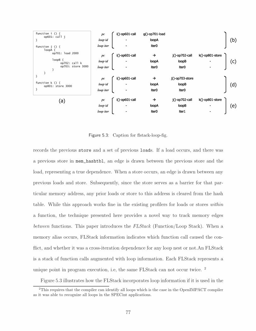
function i () {op601: call j
}
function j () {loopA {
op701: load 2000
loopB {op702: call kop703: store 3000
}}
}
function k () {op801: store 3000
}
iter0
loopA
g()-op701-load
-
-
i()-op601-call
loop iter
loop id
pc
iter0
loopA
g()-op701-load
-
-
i()-op601-call
loop iter
loop id
pc
iter0
loopB
j()-op703-store
iter0
loopA
à
-
-
i()-op601-call
loop iter
loop id
pc
iter0
loopB
j()-op703-store
iter0
loopA
à
-
-
i()-op601-call
loop iter
loop id
pc
-
-
k()-op801-store
iter0
loopB
j()-op702-call
iter0
loopA
à
-
-
i()-op601-call
loop iter
loop id
pc
-
-
k()-op801-store
iter0
loopB
j()-op702-call
iter0
loopA
à
-
-
i()-op601-call
loop iter
loop id
pc
-
-
k()-op801-store
iter1
loopB
j()-op702-call
iter0
loopA
à
-
-
i()-op601-call
loop iter
loop id
pc
-
-
k()-op801-store
iter1
loopB
j()-op702-call
iter0
loopA
à
-
-
i()-op601-call
loop iter
loop id
pc
(b)
(c)
(d)
(e)(a)
Figure 5.3: Caption for flstack-loop-fig.
records the previous store and a set of previous loads. If a load occurs, and there was
a previous store in mem_hashtbl, an edge is drawn between the previous store and the
load, representing a true dependence. When a store occurs, an edge is drawn between any
previous loads and store. Subsequently, since the store serves as a barrier for that par-
ticular memory address, any prior loads or store to this address is cleared from the hash
table. While this approach works fine in the existing profilers for loads or stores within
a function, the technique presented here provides a novel way to track memory edges
between functions. This paper introduces the FLStack (Function/Loop Stack). When a
memory alias occurs, FLStack information indicates which function call caused the con-
flict, and whether it was a cross-iteration dependence for any loop nest or not.An FLStack
is a stack of function calls augmented with loop information. Each FLStack represents a
unique point in program execution, i.e, the same FLStack can not occur twice. 2
Figure 5.3 illustrates how the FLStack incorporates loop information if it is used in the
2This requires that the compiler can identify all loops which is the case in the OpenIMPACT compileras it was able to recognize all loops in the SPECint applications.
77

program in Figure 5.3(a). When op701 is executed in loopA, the loop ID and the current
iteration number are inserted in the FLStack, as shown in Figure 5.3(b). For outer loops,
no new stack entries are needed. When entering an inner loop, such as loopB, a new
stack entry is added to record the information for all outstanding loop iterations. Thus,
when the next memory access occurs, at op801, the current FLStack looks as shown in
Figure 5.3(c). Both loopA and loopB are executing their first iterations. (The PC for
outer loop entries is drawn as a right arrow. This means to look right in the stack, which
will find the PC for the innermost loop within the same function.) This FLStack will
be recorded at address 3000 in mem_hashtbl. The next memory access is op703 which
accesses the same address. Therefore, after comparing the stacks shown in Figure 5.3(c)
and Figure 5.3(d), a mismatch is found which indicates a scheduling edge between op702 (a
function call) and op703 (a store). Since the iteration numbers at the first mismatch were
both iter0, this is not a cross-iteration edge. The next access, however, will introduce our
first cross-iteration edge. Cross-iteration edges prevent us from scheduling loop iterations
in parallel. If loopB begins its second iteration, iter1, the next memory access will be
a new dynamic instance of op801 and the FLStack will be as in Figure 5.3(e). The
iteration number for loopB has been incremented. Since op801 accesses address 3000, a
lookup in mem_hashtbl shows the access that happened in iter0 whose stack shown in
Figure 5.3(d). The first mismatch (starting from the left) is between op703 and op702.
Note that in this time, the iteration numbers are different in the stack entries where the
mismatch occurred. This edge is cross-iteration with respect to loopB and can prevent
it from getting parallelized. As the program continues to execute, if loopA iterates, the
profiler would also draw a cross-iteration edge with respect to loopA.
Since SPEC applications typically involve billions of dynamic memory accesses, several
optimizations are required to keep the runtime and memory footprint of the profiler
78

reasonable. First, the size of mem_hashtbl can get extremely large when many addresses
are accessed. We alleviate this problem by removing old entries from the hashtable. When
there are more than N addresses in the table, the oldest address is simply dropped. If N
is large enough, there would be sufficient memory conflicts within N addresses to enforce
the desired ordering and thereby the profiler is still able to catch most real dependences.
In our experiments, we found that number of captured dependences flatted out at N=512.
A second optimization of the profiler’s footprint comes with determining the number
of previous loads to store for each address in mem_hashtbl. Storing multiple loads is
necessary to track anti-dependences, but there might be many dynamic loads to a single
address. We keep the footprint reasonable by only allowing M=128 previous loads; if there
are more than M loads to an address before a store is seen, false load-load dependences
are drawn. For some programs, this results in many false load-load dependences. A
third optimization prevents storing two dynamic instances of the same static load, since a
static instruction is always scheduled at the same time. This prevents almost all load-load
dependences, and allows for a smaller profiler memory footprint. Next section presents
the results of our profile analysis.
5.2.3 Profile Results
Figure 5.4 shows the fraction of serial runtime spent in parallelizable loops identified
by the profiler. A loop is parallelizable if it contains no or few profiled cross iteration
memory dependence, and contains no cross iteration register and control dependences.
Each bar in the figure consists of two parts. The lower part represents loops with no
profiled cross iteration dependences, and the upper part represents loops with infrequent
(less than 10%) cross iteration dependences. By comparing Figures 5.4 and 5.5 with
Figures 5.1 and 5.2, we realize that many more parallel loops are identified using the profile
79

0
0.1
0.2
0.3
0.4
0.5
0.6
0.7
0.8
0.9
1
052.a
lvin
n056.e
ar
171.s
wim
172.m
grid
177.m
esa
179.a
rt183.e
quake
188.a
mm
p008.e
spre
sso
023.e
qnto
tt026.c
om
pre
ss
072.s
c099.g
o124.m
88ksim
129.c
om
pre
ss
130.li
132.ijp
eg
164.g
zip
175.v
pr
181.m
cf
197.p
ars
er
256.b
zip
2300.t
wolf
cjp
eg
djp
eg
epic
g721decode
g721encode
gsm
decode
gsm
encode
mpeg2dec
mpeg2enc
pegw
itdec
pegw
itenc
raw
caudio
raw
daudio
unepic
gre
ple
xw
cyacc
avera
ge
SPEC FP SPEC INT Mediabench Utilities
Fra
cti
on
of
se
qu
en
tia
l e
xe
cu
tio
n
Figure 5.4: Fraction of sequential execution covered by DOALL loops identified throughprofiling analysis.
information (statistically parallel loops) than using compiler memory analysis (provably
parallel loops). Likewise, the idealized CMP speedup is much higher if we parallelize
those loop. On average, parallelizable loops accounts for 28% of the serial execution using
profile information compared to 8% using static memory analysis. The improvement is
partly due to the limitation of static analysis on complex programs; however, our profiler’s
ability to identify loop structures and function calls is also a major factor. Because with
a traditional profiler, any memory dependence within a loop will prevent the loop from
being parallelized as there is no way to figure out whether the dependence is in the same
iteration or different iterations.
Although the profiler can identify more parallel loops than static analysis, most non-
SPECfp benchmarks still have very few parallel loops and thus poor speedup. These
poor results were confusing as we had observed that many loops in these applications
80

2 0
2 1
2 2
2 3
2 4
2 5
2 6
052.a
lvin
n056.e
ar
171.s
wim
172.m
grid
177.m
esa
179.a
rt183.e
quake
188.a
mm
p008.e
spre
sso
023.e
qnto
tt026.c
om
pre
ss
072.s
c099.g
o124.m
88ksim
129.c
om
pre
ss
130.li
132.ijp
eg
164.g
zip
175.v
pr
181.m
cf
197.p
ars
er
255.v
ort
ex
256.b
zip
2300.t
wolf
cjp
eg
djp
eg
epic
g721decode
g721encode
gsm
decode
gsm
encode
mpeg2dec
mpeg2enc
pegw
itdec
pegw
itenc
raw
caudio
raw
daudio
unepic
gre
ple
xw
cyacc
avera
ge
SPEC FP SPEC INT Mediabench Utilities
Sp
eeu
pfew dep
no dep
Figure 5.5: Potential speedup for idealized CMP using DOALL loops identified throughprofiling analysis.
contained no statistically significant cross-iteration memory dependences. Hence, if we
were only looking at memory dependences, the number of speculative DOALLs would be
much larger. The problem is that the loops are not DOALL due to other dependences -
namely cross iteration register and control dependences. If these dependences could be
broken by the compiler, then the number of DOALL loops would increase substantially.
The remainder of this chapter explores this direction of research, namely a set of compiler
transformations to break these dependences within the context of a speculative execution
environment.
81

023.eqntott (100%)
0%
10%
20%
30%
40%
50%
60%
70%
80%
= 0
%
<=
10%
<=
20%
<=
30%
<=
40%
<=
50%
<=
60%
<=
70%
<=
80%
<=
90%
<=
100%
Fraction of Iterations with Cross-Iteration Dependences
Fra
ctio
n o
f Loop E
xecu
tion T
ime
072.sc (88%)
0%
5%
10%
15%
20%
25%
30%
= 0
%
<=
10%
<=
20%
<=
30%
<=
40%
<=
50%
<=
60%
<=
70%
<=
80%
<=
90%
<=
100%
Fraction of Iterations with Cross-Iteration Dependences
Fra
ctio
n o
f Loop E
xecu
tion T
ime
124.m88ksim (85%)
0%
5%
10%
15%
20%
25%
30%
35%
40%
= 0
%
<=
10%
<=
20%
<=
30%
<=
40%
<=
50%
<=
60%
<=
70%
<=
80%
<=
90%
<=
100%
Fraction of Iterations with Cross-Iteration Dependences
Fra
ctio
n o
f Loop E
xecu
tion T
ime
129.compress (100%)
0%
2%
4%
6%
8%
10%
12%
14%
16%
18%
= 0
%
<=
10%
<=
20%
<=
30%
<=
40%
<=
50%
<=
60%
<=
70%
<=
80%
<=
90%
<=
100%
Fraction of Iterations with Cross-Iteration Dependences
Fra
ctio
n o
f Loop E
xecu
tion T
ime
132.ijpeg (99%)
0%
10%
20%
30%
40%
50%
60%
70%
80%
= 0
%
<=
10%
<=
20%
<=
30%
<=
40%
<=
50%
<=
60%
<=
70%
<=
80%
<=
90%
<=
100%
Fraction of Iterations with Cross-Iteration Dependences
Fra
ctio
n o
f Loop E
xecu
tion T
ime
164.gzip (100%)
0%
5%
10%
15%
20%
25%
= 0
%
<=
10%
<=
20%
<=
30%
<=
40%
<=
50%
<=
60%
<=
70%
<=
80%
<=
90%
<=
100%
Fraction of Iterations with Cross-Iteration Dependences
Fra
ctio
n o
f Loop E
xecu
tion T
ime
254.gap (53%)
0%
10%
20%
30%
40%
50%
60%
= 0
%
<=
10%
<=
20%
<=
30%
<=
40%
<=
50%
<=
60%
<=
70%
<=
80%
<=
90%
<=
100%
Fraction of Iterations with Cross-Iteration Dependences
Fra
ctio
n o
f Loop E
xecu
tion T
ime
256.bzip2 (93%)
0%2%4%
6%8%
10%12%14%16%
18%20%
= 0
%
<=
10%
<=
20%
<=
30%
<=
40%
<=
50%
<=
60%
<=
70%
<=
80%
<=
90%
<=
100%
Fraction of Iterations with Cross-Iteration Dependences
Fra
ctio
n o
f Loop E
xecu
tion T
ime
cjpeg (97%)
0%
10%
20%
30%
40%
50%
60%
= 0
%
<=
10%
<=
20%
<=
30%
<=
40%
<=
50%
<=
60%
<=
70%
<=
80%
<=
90%
<=
100%
Fraction of Iterations with Cross-Iteration Dependences
Fra
ctio
n o
f Loop E
xecu
tion T
ime
epic (100%)
0%10%20%
30%40%50%60%70%80%
90%100%
= 0
%
<=
10%
<=
20%
<=
30%
<=
40%
<=
50%
<=
60%
<=
70%
<=
80%
<=
90%
<=
100%
Fraction of Iterations with Cross-Iteration Dependences
Fra
ctio
n o
f Loop E
xecu
tion T
ime
g721decode (89%)
0%
10%
20%
30%
40%
50%
60%
70%
80%
90%
= 0
%
<=
10%
<=
20%
<=
30%
<=
40%
<=
50%
<=
60%
<=
70%
<=
80%
<=
90%
<=
100%
Fraction of Iterations with Cross-Iteration Dependences
Fra
ctio
n o
f Loop E
xecu
tion T
ime
mpeg2enc (100%)
0%
20%
40%
60%
80%
100%
120%
= 0
%
<=
10%
<=
20%
<=
30%
<=
40%
<=
50%
<=
60%
<=
70%
<=
80%
<=
90%
<=
100%
Fraction of Iterations with Cross-Iteration Dependences
Fra
ctio
n o
f Loop E
xecu
tion T
ime
mpeg2dec (100%)
0%10%20%30%40%50%60%
70%80%90%
100%
= 0
%
<=
10%
<=
20%
<=
30%
<=
40%
<=
50%
<=
60%
<=
70%
<=
80%
<=
90%
<=
100%
Fraction of Iterations with Cross-Iteration Dependences
Fra
ctio
n o
f Loop E
xecu
tion T
ime
pegwitenc (68%)
0%
10%
20%
30%
40%
50%
60%
70%
80%
90%
= 0
%
<=
10%
<=
20%
<=
30%
<=
40%
<=
50%
<=
60%
<=
70%
<=
80%
<=
90%
<=
100%
Fraction of Iterations with Cross-Iteration Dependences
Fra
ctio
n o
f Loop E
xecu
tion T
ime
unepic (100%)
0%
10%
20%
30%
40%
50%
60%
= 0
%
<=
10%
<=
20%
<=
30%
<=
40%
<=
50%
<=
60%
<=
70%
<=
80%
<=
90%
<=
100%
Fraction of Iterations with Cross-Iteration Dependences
Fra
ctio
n o
f Loop E
xecu
tion T
ime
All Loops w/Training Input
Loops Selected During Trainingw/Evaluation Input
All Loops w/Training Input
Loops Selected During Trainingw/Evaluation Input
Figure 5.6: Distribution of execution time for loops with varying fractions of iterationswith cross-iteration dependences. The left bar represents the breakdown of allloops for a training input. The right bar represents the breakdown of the zerocross iteration dependence loops on the training input using a larger, evaluationinput for the benchmark.
5.2.4 Predictability of Cross-Iteration Memory Dependences
To determine the viability of predicting which loops are parallelizable based on pro-
filing information, we performed a study of the nature of cross-iteration memory depen-
dences. Register dependences are not considered because they are obvious to the compiler.
For all loops in a program, we profile to identify cross-iteration memory dependences. If
two memory operations from different iterations access the same address, and one is a
store, there is a cross-iteration dependence. For each loop, we can then obtain the frac-
82

tion of iterations with a cross-iteration dependence, we call this the dependence fraction.
Figure 5.6 shows histograms of how much time is spent in loops with different dependence
fractions across various applications in the SPEC and MediaBench suites. The left set of
bars for each benchmark (gray bars) show the distribution of dependence fractions for a
training input. The y-axis represents how much serial execution time was spent in loops
with a particular dependence fraction; the percentage is out of the total execution time
spent in loops. The portion of the benchmark spent within loops is shown at the top of
each graph in parenthesis after the benchmark name.
Examining this structure, we hypothesize that the loops with zero dependences are
unlikely to have dependences for other input sets, and would be good candidates for
parallelization. To check this, we profiled only these loops using an evaluation input for
the benchmark; the result is also presented in Figure 5.6. The right set of bars (dark
gray bars) show the distribution of dependence fractions of the loops that we expect to be
zero (since they were zero in the training input). For most benchmarks, the hypothesis is
strongly supported. One notable exception is 256.bzip2, where one loop representing 7%
of the execution changes its memory dependence behavior significantly with the larger
input set.
One particular concern in systems that hardware to detect such memory dependences
(e.g., coherent caches) is false sharing. The data in Figure 5.6 was consistent across cache
line sizes of 4 to 64 bytes. While this is not a comprehensive study, we conclude that
false sharing does not significantly affect the identification of statistical DOALL loops.
This confirms the false sharing results presented in [68]. With highly predictable memory
dependences, these loops are promising candidates for speculative parallelization; however,
we have thus far ignored the feasibility of handling register dependences.
83

5.3 Uncovering Hidden Loop Level Parallelism
As shown in the previous sections, without any code transformation, out-of-the-box
loop level parallelization opportunities for general applications are limited, even with TLS
hardware support. After manually studying a wide range of loops, we found that many
parallel opportunities were hidden beneath the seemingly sequential code. With proper
code transformations, critical cross iteration dependences can be untangled resulting in
many more speculative DOALL loops. In this section, we first introduce our code gener-
ation scheme for speculative DOALL loops. It handles both counted loop and uncounted
loop with cross iteration control dependences. Subsequently, we present techniques to
handle cross iteration dependences that hinder loop level parallelism. In addition to some
well-known techniques, we introduce three novel transformations to untangle register and
memory dependences: speculative loop fission, speculative prematerialization, and isola-
tion of infrequent dependences.
5.3.1 Code Generation
After choosing candidate loops for parallelization using the profile information, the
compiler distributes loop execution across multiple cores. In this work, we categorize
DOALL loops into DOALL-counted and DOALL-uncounted. In DOALL-counted, the
trip count is known when the loop is invoked (note, the trip count is not necessarily a
compile-time constant). However, for DOALL-uncounted, the trip count is unknown until
the loop is fully executed. While loops and for loops with conditional break statements
are two examples of DOALL-uncounted loops that occur frequently. In these cases, the
execution of every iteration depends on the outcome of exit branches in previous iterations.
Therefore, these loops contain cross iteration control dependences. In this section, we
84

introduce our code generation framework for handling control dependences and executing
both speculative DOALL-counted and DOALL-uncounted loops.
Figure 5.7 shows the detailed implementation of our code generation framework. In the
proposed scheme, the loop iterations are divided into chunks. The operating system passes
the number of available cores and the chunk size to the application. Our framework is
flexible enough to use any number of available cores for loop execution. We insert an outer
loop around the original loop body to manage the parallel execution between different
chunks. Following is a description of the functionality of each segment in Figure 5.7.
Spawn: To start, the master thread spawns threads containing chunks of loop iter-
ations. It sends the necessary parameters (chunk size, thread count, etc.) and live-in
values to all threads.
Initialization: In the initialization block, all participating cores receive the required
parameters and live-in values. Since live-in values are not changed in the loop3, we only
send them once for each loop execution. This block also computes the starting iteration,
IS, for the first chunk. After initialization, each core manages its own iteration start value,
thus parallel execution continues with minimum interaction among the threads.
In order to capture the correct live-out registers after parallel loop execution, we use
a set of registers called last-upd-idx, one for each conditional live-out (i.e., updated in an
if-statement). When a conditional live-out register is updated, we set the corresponding
last-upd-idx to the current iteration number to keep track of the latest modifications to the
live-out values. If the live-out register is unconditional (i.e., updated in every iteration),
the final live-out value can be retrieved from the last iteration and no last-upd-idx is
needed.
Abort Handling: The abort handler is called when a transaction aborts. If the TM
3If a live-in value is changed in the loop, it generates a cross iteration register dependence and theloop cannot be parallelized.
85

RECV live_outs and last_upd_idx values Set live_outj to the last updated value
for (all live_outs) SEND(live_outj,0)
SEND(last_upd_idxj,0)
DONE
Receive CS, SS, TC and live-insIS = IS_init + CS * SS * thread_idfor (all live_outs)
last_upd_idxi = -1;
THREAD0?
Initialization
Parallel Loop
Consolidation
Abort Handler
for (i=IS;i<IE;i+=SS) // original loop code live_outk =… //kth liveout assignment last_upd_idxk= i; if (brk_cond) local_brk_flag = 1;
break;
XBEGIN if (global_brk_flag) break;
IE = min(IS+CS*SS,n)
perm = RECV(THREADj-1)XCOMMITif (local_brk_flag) global_brk_flag = 1; kill_other_threads;elseif (IE < n) SEND(perm,THREADj +1)
IS+=CS * TC * SS;
if (IS < n) & (!local_brk_flag)
Spawn jobs to available cores
Send CS, SS, TC and live-ins to all threadsSpawn
Yes No
Figure 5.7: Detailed code generation framework for speculative loop parallelization.Transaction scope is marked by XBEGIN and XCOMMIT. (CS: chunk size,IS: iteration start, IE: iteration end, SS: step size, TC: thread count)
86

hardware does not backup the register file, we can use the abort handler to recover certain
register values in case of transaction abort. More specifically, we need to recover the live-
out and last-upd-idx register values. We need to backup these registers at the beginning
of each transaction, and move the backup value to the registers in the abort handler.
Moreover, we also add recovery code in the abort handler for some of our transformations
as described in the next section.
Parallel Loop: The program stays in the parallel loop segment as long as there are
some iterations to run and no break has happened. In this segment, each thread executes
a set of chunks. Each chunk runs iterations from IS to IE. The value of IS and IE are
updated after each chunk using the chunk size (CS), thread count (TC) and step size
(SS).
Each chunk of iterations are enclosed in a transaction, demarcated by XBEGIN and
XCOMMIT instructions. The transactional memory monitors the memory accessed by
each thread. It aborts the transaction running higher iterations if a conflict is detected,
and restarts the transaction from the abort handler.
Commit Ordering:Chunks are forced to commit in-order to maintain correct exe-
cution and enable partial loop rollback and recovery. In order to minimize the required
bookkeeping for this task, we use a distributed commit ordering technique in which each
core sends commit permission to the next core after it commits successfully. These per-
missions are sent in the form of dummy values to the next core. The RECV command
near the end of the main block causes the core to stall and wait for dummy values from
the previous core.
Break Handling: For uncounted loops, if a break happens in any thread, we don’t
want to abort higher transactions immediately, because the execution of the thread is
speculative and the break could be a false break. Therefore, we use a local variable
87
local brk flag in each thread to keep track of if a chunk breaks. If the transaction commits
successfully with local brk flag set, the break is not speculative any more, and a transaction
abort signal is sent to all threads using a software or hardware interrupt mechanism. In
addition, a global brk flag is set, so that all threads break the outer loop after restarting
the transaction as a result of the abort signal. The reason for explicitly aborting higher
iterations is that if an iteration is started by misspeculation after the loop breaks, it could
produce an illegal state. The execution of this iteration might cause unwanted exceptions
or might never finish if it contains inner loops.
Consolidation: After all cores are done with the execution of iteration chunks, they
enter the consolidation phase. In this period, each core sends its live-outs and last-
upd-idx array to THREAD0 that selects the last updated live-out values. All threads
are terminated after consolidation and THREAD0 continues with the rest of program
execution.
We carefully designed the framework to keep most of the extra code outside the loop
body, so they only execute once per chunk . The overhead in terms of total dynamic
instructions is quite small.
5.3.2 Dependence Breaking Optimizations
This section focuses on breaking cross iteration register dependences that occur when
a scalar variable is defined in one iteration and used in another. First, we examine
several traditional techniques that are commonly used by parallelizing compilers for sci-
entific applications: variable privatization, reduction variable expansion, and ignoring
long distance memory dependences. These optimizations are adapted to a speculative
environment. Then, we propose three optimizations specifically designed for a specula-
tive environment: speculative loop fission, speculative prematerialization and infrequent
88

1: while (node) {2: work(node);3: node = node->next; }
// Sequential count = 0;1: while (node) {4: node_array[count++]= node;3: node = node->next; }
// Parallel XBEGIN node = node_array[IS]; i = 0;1': while (node && i++ < CS) {2: work(node)3': node = node->next } if (node != node_array[IS+CS] kill_higher_iter_THREADs(); XCOMMIT
(a)
(b)
(c)
rf
rfrf
1
2
3
c
c
m?
rf
rfrf
1
4
3
c
c
rf
rfrf
1
2
3'
c
c
m?
rf
rfrf
1'
2
3'
c
c
m?
SequentialParallel
...
(d)
Figure 5.8: Speculative loop fission (a) Original loop (b) Original data flow graph (c) Dataflow graph after fission (d) Loop after fission - (rf: register flow dependence, c:control dependence, m?: unlikely cross-iteration memory dependence
dependence isolation. These transformations are adaptations of existing ones used in the
scientific and ILP compilers.
5.3.2.1 Traditional Dependence Breaking Optimizations
Variable privatization. Cross iteration input, anti- and output dependences can
be removed by register privatization. Since each core has a separate register file, register
accesses in different cores are naturally privatized. Live-in scalars are broadcast to each
core during initialization, thus all false dependences on scalars are removed. Handling
output dependences for live-out variables is tricky. Since the value of a live-out variable
is used outside the loop, we need to find out which core performed the last write to the
register. This is not obvious if the register is updated conditionally. As described in the
previous section, the code generation template handles this case by assigning an integer
value on each core for each live-out register. This value is set to the last iteration index
where the live-out variable is written. The compiler inserts code after the loop (in the
89

consolidation block in Figure 5.7) to set the live-out registers to their last updated values
in the loop based on the stored iteration index.
Reduction variable expansion. Reduction variables, such as accumulators or vari-
ables that are used to find a maximum or minimum value, cause cross iteration flow
dependences. The most common case is the sum variable when all elements of an array
are summed. These dependences can be removed by creating a local accumulator (or
min/max variable) for each core, and privately accumulating the totals on each core. Af-
ter the loop and in the consolidation block, local accumulators are summed or the global
min/max is found amongst the local min/max’s.
Ignoring long distance memory dependences. When the number of iterations
between two memory dependences is larger than some threshold, there is an opportu-
nity for parallelization by simply ignoring the dependence. Intuitively, if the distance
between memory accesses is n, the compiler can make n−1 iterations execute in parallel.
Subsequently, if we set the chunk size as cross iteration distance/number of cores, our
scheme in Section 5.3.1 generates the proper code for parallel execution of the loop.
5.3.2.2 Speculative Loop Fission
By studying benchmarks, we observed that many loops contain large amounts of par-
allel computation, but they cannot be parallelized due to a few instructions that form
cross iteration dependence cycles. We call these loops almost DOALL loop as the bulk of
the loop is DOALL, but a small recurrence cycle(s) inhibits parallelization. The objec-
tive of speculative loop fission is to split the almost DOALL into two parts: a sequential
portion that is run on one core followed by a speculative DOALL loop that can be run
on multiple cores. The basic principles of this optimization are derived from traditional
loop fission or distribution [4].
90

for (k=0;k<num_nets_affected;k++) {
inet = nets_to_update[k];
if (net_block_moved[k] == FROM_AND_TO)
continue;
if (net[inet].num_pins <= SMALL_NET) {
get_non_updateable_bb (inet,
&bb_coord_new[bb_index]);
}
......
......
bb_index++;
}
for (k=0;k<num_nets_affected;k++) {
if (net_block_moved[k] == FROM_AND_TO)
continue;
bb_index_array [k] = bb_index;
bb_index++;
}
XBEGIN bb_index = bb_index_array[IS];
for (k = IS; k < IS + CS ; k++) { inet = nets_to_update[k];
if (net_block_moved[k] == FROM_AND_TO)
continue;
if (net[inet].num_pins <= SMALL_NET) {
get_non_updateable_bb (inet,
&bb_coord_new[bb_index]);
}
......
......
bb_index++;
}
if (bb_index != bb_index_array[k]) abort_higher_threads;XCOMMIT
Abort_handler:
bb_index = bb_index from aborting core; k = k from the aborting core;
for (;k<num_nets_affected;k++) { if (net_block_moved[k] == FROM_AND_TO) continue; bb_index_array [k] = bb_index; bb_index++;
}
Spawn parallel chunks with abort handler;
(a)
(b)
(c)
Figure 5.9: Example of speculative loop fission from 175.vpr: (a) original loop (b) loopafter fission (c) abort handler.
Figure 5.8(a) shows a classic example of such a loop. A linked list is iterated through,
with each iteration doing some work on the current node. Figure 5.8(b) shows the data
dependence graph for the loop, with the important recurrence of operation 3 to itself.
Note that there may be an unlikely memory dependence between operations 2 and 3 as
indicated by the “m?” edge in the graph. Such a situation occurs when the compiler
analysis cannot prove that the linked list is unmodified by the work function. For this
loop, the sequential portion consists of the pointer chasing portion (i.e., operation 3) and
the DOALL portion consists of the work performed on each node (i.e., operation 2).
The basic transformation is illustrated in Figure 5.8(c). The strongly connected com-
ponents, or SCCs, are first identified to compose the sequential portion of the loop.
Dependences that will be subsequently eliminated are ignored during this process. These
include control dependences handled by the DOALL-uncounted schema (i.e., the control
dependence from operation 1 to 3), unlikely memory dependences (i.e., the memory de-
91

pendence from operation 2 to 3), and register dependences caused by reduction variables.
In this example, the SCC is operation 3. The sequential portion is then populated with
two sets of nodes. First, copies of all dependence predecessors of the SCC are added (op-
eration 1 in Figure 5.8(c)). Second, a new operation is introduced for each register flow
edge that is cut between the SCCs and the remaining operations. In the example, there is
a register flow edge from operation 3 to 2. A new operation is created (operation 4) that
stores the value communicated via the edge into an array element. For this example, each
node pointer is stored into the array. In essence, the register flow dependence is converted
into a through-memory dependence. The result is the dependence graph shown on the
left portion of Figure 5.8(c) and the code shown at the top of Figure 5.8(d).
The parallel portion of the loop consists of the entire original loop, including the SCCs,
with a few modifications as shown in Figures 5.8(c) (right portion) and 5.8(d) (bottom
portion). Each parallel chunk is seeded with a single value computed in the sequential
loop for each register flow edge that was cut. In the example, node is set to node array[IS]
or the index of the starting iteration of the chunk. The body of the DOALL is identical to
the original loop, except that only a fixed number of iterations are performed, CS or chunk
size. Note that each parallel chunk is sequential, yet all parallel chunks are completely
decoupled due to array variables produced by the sequential loop (i.e., node array).
The final change is a test to ensure that each live-out SCC variable has the same value
that was computed in the sequential loop. For the linked list example, this tests whether
the current parallel chunk modified the starting element of the next chunk. This test
combined with the transaction commit ensures that the linked list was not modified during
the parallel portion. In cases where the compiler can prove no modifications are possible,
this check is not necessary. The final parallel code is presented in Figure 5.8(d). Note that
only the transaction scope portion of the code is shown for clarity. This code is dropped
92

for (...) {1: current = … ;2: work(last);3: last = current; }
XBEGIN1': current = 3': last = for (...) {1: current = … ;2: work(last);3: last = current; } XCOMMIT
(a) (b)
1
2
3
(c)
Figure 5.10: Example of speculative prematerialization: (a) original loop, (b) dataflowgraph, and (c) loop after transformation.
into the DOALL-uncounted template in Figure 5.7 to complete the parallelization.
Our loop fission scheme is different from traditional loop fission technique in that both
the sequential and parallel loops are speculative. Since the sequential loop contains com-
putations from every iteration, it could conflict with one or more of the parallel chunks.
For example, in Figure 5.8(a), the work function could modify the linked list. This means
that node array contains one or more incorrect values. Such a memory dependence vio-
lation must be detected and rollback performed. The combination of the transactional
semantics and the additional tests added after each parallel chunk to test the SCC vari-
ables ensure there are no unexpected memory dependences between two parallel chunks
(transaction commit) and between the sequential and parallel chunks (explicit test in-
serted by the compiler). To simplify the problem, we don’t allow inclusion of any store
instruction in the sequential loop besides the ones that write to the new arrays. Our
experiments show that very few fission candidates are lost by this requirement. When a
parallel loop chunk reaches the end of its execution, it can commit only if all previous
chunks have committed and no conflicts are detected, thereby ensuring correctness.
When the abort handler is invoked due to a memory dependence conflict, it must first
abort all threads executing higher numbered iterations. Then, it restarts the execution of
the sequential loop to re-initialize all the relevant values for the new arrays (i.e., node array
in the example). To ensure that modifications to data structures by later iterations do not
93
affect earlier iterations, the sequential loop is run only from the starting iteration of the
next thread after abort (iteration start + chunk size or IS+CS) to reset only the relevant
portion of the new array(s).
To show a real example of speculative loop fission, Figure 5.9(a) presents an important
almost DOALL loop from the SPECint application 175.vpr. This example is different
from the previous example in that it is not a linked list traversal. The variable bb index
carries a cross iteration register dependence. The variable is not an induction variable
because it is not updated in every iteration due to the continue statement. The split loops
are shown in Figure 5.9(b). The first loop is the sequential loop and contains the cross
iteration dependences. It produces value of bb index on every iteration and stores them
to a new array called bb index array. The second loop is the parallel loop, where each
chunk is decoupled through the use of bb index array. Finally, the abort handler for the
loop is presented in Figure 5.9(c).
Two alternatives for parallelizing almost DOALL loops are DOACROSS [4] and specu-
lative decoupled software pipelining (DSWP) [75]. We consider speculative fission a better
option than DOACROSS for two reasons. First, DOACROSS does not work with itera-
tion chunking. If chunks of many iterations are executed in the DOACROSS manner, the
first iteration in a chunk has to wait for data from the last iteration of the previous chunk,
which basically sequentializes execution. For loops with small bodies, iteration chunking
is very important to get performance improvement. Second, DOACROSS execution is
very sensitive to the communication latency between threads because each iteration has
to wait for data from the previous iteration. With speculative loop fission, the commu-
nication between the sequential part and the parallel part can happen in parallel and
thereby the total execution time would be much shorter.
Speculative DSWP converts almost DOALL loops into a producer-consumer pipeline.
94

for (colctr = compptr ->downsampled _width - 2; colctr > 0; colctr--) {
nextcolsum = GETJSAMPLE (*inptr0++) * 3 + GETJSAMPLE (*inptr1++); *outptr++ = (JSAMPLE ) ((thiscolsum * 3 + lastcolsum + 8) >> 4); *outptr++ = (JSAMPLE ) ((thiscolsum * 3 + nextcolsum + 7) >> 4); lastcolsum = thiscolsum ; thiscolsum = nextcolsum ;}
colctr = IS - 2; inptr0 = inptr0_init;inptr1 = inptr0_init;
nextcolsum = GETJSAMPLE (*inptr0++)*3 + GETJSAMPLE (*inptr1++);thiscolsum = nextcolsum ;
colctr = ++;nextcolsum = GETJSAMPLE (*inptr0++)*3 + GETJSAMPLE (*inptr1++);lastcolsum = thiscolsum ; thiscolsum = nextcolsum ;
for (colctr = IS;colctr >IS–CS;colctr --) { // The original loop body goes here ......}
Init
inductions
Iteration
iter_start -2
Iteration
iter_start -1
Chunk from
iter_start
Figure 5.11: Example of speculative prematerialization from djpeg.
This has the advantage of overlapping the sequential and parallel portions. However,
when the two portions are not relatively equal sized, the pipeline can be unbalanced. This
problem can be alleviated by replicating pipeline stages. We believe DOALL execution is
more scalable and more compatible with conventional transactional semantics.
5.3.2.3 Speculative Prematerialization
A special type of cross iteration register dependence can be removed through a trans-
formation called speculative prematerialization. The idea of prematerialization is to ex-
ecute a small piece of code before each chunk to calculate the live-in register values, so
the chunks can be executed in parallel instead of waiting for all previous iterations to
finish. Rematerialization is a technique commonly used by register allocators where its
more efficient to recompute a value than store it in a register for a long period of time.
Here the objective is different, but the process is similar.
Prematerialization can remove cross iteration dependences on registers that are not
part of dependence cycles and are defined in every iteration. For each register that satisfies
those two conditions, pre-execution of at most one iteration will generate the live-in value
95

for( j=0; j<=nstate; ++j ){if( tystate [j] == 0 ) continue ;if( tystate [j] == best ) continue ;count = 0;cbest = tystate [j];for (k=j; k<=nstate; ++k)if (tystate [k]==cbest) ++count;if ( count > times) {best = cbest;times = count;
}}
j=0;while (j<=nstate ){for( ; j<=nstate; ++j ){if( tystate [j] == 0 ) continue ;if( tystate [j] == best ) continue ;count = 0;cbest = tystate [j];for (k=j; k<=nstate ; ++k)if (tystate [k]==cbest) ++count;
if ( count > times) {break;
} if (count > times) {best = cbest;times = count; j++;}
}
(c) (d)
1:
2:
m
m
A
B
C
1:
2:
mm
A
BC
C’
(a) (b)
Figure 5.12: Example of dependence isolation: (a) mechanics of transformation for anabstract loop, (b) example loop from yacc.
for a chunk. If a loop contains n registers that need to be prematerialized, at most n
iterations need to be pre-executed.
Figure 5.10 illustrates the transformation. The original loop and dataflow graph are
presented in Figures 5.10 (a) and (b). There is a cross iteration register flow edge from
operation 3 to 2 corresponding the the variable last. The transformation is accomplished
by peeling off a copy of the source of the register flow dependence and all its dependence
predecessors. In this case, the source of the register flow dependence (operation 3) and its
dependence predecessor (operation 1) are peeled and placed in the loop preheader. The
resultant loop is shown in Figure 5.10(c). On the surface, this loop is still sequential as the
96

dependence between operations 3 and 2 has not been eliminated. However, the peeling
decouples each chunk from the prior chunk allowing the chunks to execute in parallel.
One important thing to note is that the prematerialization code is speculative because
other iterations could modify variables it uses. This is akin to speculative fission where
the linked list is modified during its traversal. In the simple example, a pointer used
to compute current could be changed, thereby invalidating the prematerialized variables.
Thus, the prematerialization code must be part of the transaction that contains the chunk.
If any memory conflict is detected in the prematerialization code or the loop itself, the
transaction corresponding to higher number iterations is aborted and restarted.
To illustrate a real application of prematerialization, Figure 5.11 shows a loop in the
application djpeg from MediaBench. The variables lastcolsum, thiscolsum, and nextcol-
sum form a 3-wide sliding window in the loop. Variables nextcolsum and lastcolsum both
carry cross iteration dependences that prevent DOALL execution. Speculative premate-
rialization can be applied because the value of nextcolsum and lastcolsum are defined in
every iteration, and the cross iteration dependences do not form cycles. The right half of
Figure 5.11 shows the parallel code after prematerialization. A prematerialization block
is inserted before each chunk to compute the live-in values for nextcolsum and lastcolsum.
In the prematerialization code, portions of the previous two iterations are executed to
prematerialize two variables.
5.3.2.4 Infrequent Dependence Isolation
Another form of almost DOALL loops are loops with infrequently occurring cross-
iteration dependences. The sources or sinks of the dependence edges are contained in
infrequently executed conditional clauses. Thus, the majority of the time the loops are
DOALL. Isolation does not break any dependences, but rather transforms the control flow
97

structure of the code to allow the compiler to parallelize the portion of the loop that is
DOALL. The transformation is similar to hyperblock formation, but again the objectives
are changed [43].
Cross-iteration register and memory dependences are eligible for isolation as well as
calls to libraries where the compiler does not have complete memory dependence informa-
tion. Library calls are typically treated conservatively and and thus inhibit paralleliza-
tion. Isolation optimizes the common case by restructuring a loop into a nested loop.
The schematic transformation is illustrated in Figure 5.12(a)(b). The example loop con-
sists of three basic blocks, A, B, and C. A dependence cycle exists between operations 1
and 2, contained in blocks A and B, respectively. Assume that block B is infrequently
executed. Isolation converts the A-B-C loop into a nested loop structure as shown in
the figure. The inner loop contains the frequent, DOALL portion, namely A-C. And, the
outer loop contains the sequential portion, namely A-B-C. Block C is duplicated as in
hyperblock formation to eliminate side entrances into the loop. The resultant inner loop
is an DOALL-uncounted. When control enters block B, parallel execution is aborted, and
the cross iteration dependence is properly enforced.
Figure 5.12(c)(d) illustrates the application of dependence isolation to a loop from
the Unix utility yacc. Figure 5.12(c) shows the original code in which the outer for loop
is not parallellizable due to two cross-iteration register dependences that are shown by
arrows. However, according to the profile information, the if statement at the bottom
of the loop rarely evaluates to True. Therefore, we can transform the loop to that in
Figure 5.12(d). This code is transformed by adding an outer while loop and the unlikely
if block is replaced by a break statement. When the condition count > times is True,
the outer for loop will break and the if statement in new while loop is entered. After
execution of this block, the for loop continues running from the iteration it left off. The
98

outer for is now DOALL.
5.4 Loop Selection
Simply parallelize a loop can sometimes reduce the performance of the program be-
cause of the parallelization overhead. The limited amount of available cores also prevents
the parallelization of loops in all nesting levels. The compiler need to select and paral-
lelize a subset of all the parallelizable loops, such that the overall performance gain is
maximized. This section discusses the loop selection algorithm. The algorithm selects
loops based on profile information, loop nesting structure, and available resources.
5.4.1 Estimating Performance Gain for Individual Loops
The compiler first estimates the performance gain for parallelizing each loop individ-
ually. The performance gain for loop L can be calculated as follows:
G(L, n) = S(L) − P (L, n) (5.1)
G(L, n) is the performance gain measured in number of cycles for loop L with n
cores. S(L) is the sequential execution time for loop L from profile. P (L, n) is the
estimated parallel execution time on n cores. Depending on the type of the loop (counted,
uncounted) and transformations needed to parallelize the loops (reduction expansion,
speculative fission, infrequent dependence isolation, prematerialization), the formula to
compute P (L, n) varies. For a basic counted or uncounted loop, P (L, n) can be computed
as below:
P (L, n) = Tloopbody + Toverhead + Trollback (5.2)
99

Tloopbody is the time spent in the parallel loop body. It includes the time spent in
parallel chunks, as well as the time spent in ”leftover” iterations that can not be evenly
divided into parallel chunks.
Toverhead includes three parts: per iteration overhead, per chunk overhead, and per
loop overhead. Per iteration overhead is the most expensive because it happens in every
iteration. The code generation framework incurs per iteration overhead only if the loop
contains conditionally updated live out register. Per chunk overhead includes the XBEGIN
and XCOMMIT to start and commit a transaction; the computation to update iteration
start (IS) and iteration end (IE); the SEND and RECV to pass commit permission; and
the checking of the global commit flag for uncounted loops. If the compiler choose the
chunk size intelligently, the number of chunks should be moderate. Per loop overhead
happens every time the loop is invoked. It includes the spawning overhead, the loading
of live-in values, the gathering of live-out values, and the initialization of break flag for
uncounted loops.
Trollback is the overhead for rolling back the execution. Everytime a conflict is detected,
a chunk of iterations will be re-executed. The frequency of the rollback is estimated using
profiled cross iteration dependence frequency.
For loops that require transformations, the transformation overheads are also consid-
ered when caculating the parallel execution time.
5.4.2 Loop Selection
If nested transactions are not allowed, only one loop can be parallelized at any given
time. For a certain loop, if any of its outer loop or inner loop is chosen to be parallelized,
it cannot be selected to parallelize. The goal of loop selection is to select a set of loops to
parallelize under such constraint to maximize the overall performance.
100

Input: Loop Graph (LG)
Output: Set of selected nodes (selected)
foreach Node n in LG do
compute performance gain G(n);
end
foreach Node n in LG in reverse topological order do
max gain(n) = G(n);children gain = 0;foreach Child node cn of n do
children gain += max gain(cn);
end
if max gain(n) < children gain then
max gain(n) = children gain;
end
end
BFS queue.enqueue(root nodes in LG);while BFS queue not empty do
n = dequeue (BFS queue);if G(n) == max gain(n) then
selected.add (n);
end
else
BFS queue.enqueue( children nodes of n);
end
end
return selected;
Algorithm 1: Loop selection algorithm
The selection algorithm is illustrated in Algorithm 1. The input for the selection
algorithm is the loop graph for the program, Each node in the loop graph represents a
loop. There is an edge from A to B if loop B is directly nested in loop A. The loop graph
consists of multiple trees, Every outer most loop in a procedure is a root for a tree. The
inner most loops will be leaves for the trees.
The algorithm then calculate the potential gain for parallelizing each loop using the
method described in section 5.4.1, and assign the gains as weights for the nodes in the
graph. The loop selection problem becomes selecting a set of nodes from the graph such
that the sum of the weight of selected nodes are maximized, under the constraint that at
most 1 node can be selected from any path from a root to a leaf node.
101
After computing the node weights, The compiler computes the max gain for every
node. The max gain for a node is the maximum possible performance gain achieved by
selectively parallelizing the loop and all its inner loops, subjecting to the contraint that
only one loop can be parallelized in any path to a leaf node. The max gain for a node
can be computed as follows:
max gain(node) = max(G(node),∑
n∈CHILD(node)
max gain(n)) (5.3)
The compiler visits all nodes from leaves to roots using reverse topological order. The
time complexity to compute max gain is O(n), where n is the number of nodes in the
loop graph.
After the computation of max gain, the compiler selects loops using a breadth first
search (BFS) order, such that outer loops are considered before inner loops. If the esti-
mated gain and the max gain for a node is the same, the maximum gain can be achieved
by parallelizing this loop. The node will be selected and all its children nodes will not
be considered. If the estimated gain is less than the max gain, the children nodes will be
considered in BFS order.
All three parts of the algorihtm, gain computation, max gain computation and node
selection have complexity of O(n), thus the overall time complexity for the algorithm is
O(n).
5.5 Related Work
There is a large amount of previous work in TLS [6, 27, 31, 55, 67, 68, 74, 84] and TLDS [68,
69] that propose speculative execution of threads along with the required architectural
support. For example, Multiscalar architectures [67] support TLS, and prior work [76]
102

has studied graph partitioning algorithms to extract multiple threads; however, this does
not eliminate unnecessary dependences in the same way this work does. Our work builds
upon previous research and proposes compiler transformations to expose more specula-
tive parallelism in loops. In particular, the Hydra project [55] classifies loops to different
categories and introduces compiler techniques to parallelize the code. This work extends
those ideas with compiler techniques for loop identification, selection, transformation,
and code generation. MSSP [84] transforms code into master and slave threads to ex-
pose speculative parallelism. It creates a master thread that executes an approximate
version of the program containing a frequently executed path, and slave threads that run
to check results. Conversely, our transformations have different execution models. Both
speculative fission and infrequent path isolation create parallel threads executing different
iterations. No dedicated checker threads are needed.
Several works have proposed full compiler systems [6, 19, 42, 59, 69] that target loop-
level and method-level parallelism. In [42], the authors introduce a compilation framework
for transformation of the program code to a TLS compatible version. Profile information
is also used to improve speculation choices. The Mitosis compiler [59] proposes a general
framework to extract speculative threads as well as pre-computation slices (p-slices) that
allow speculative threads to start earlier. Our prematerialization is similar to p-slices,
but prematerialization is highly targeted to loop recurrences that can be unwound to
decouple iterations and must maintain register and control dependences, while p-slices
can speculatively prune paths. Du et al. [19] propose a compilation framework in which
candidate loops for speculation are chosen based on a profile-guided misspeculation cost.
A general compilation strategy for TLS is introduced in [6]. Their method is applicable
to loops as well as other parts of the program. Due to the application of this general
approach, many opportunities in loop transformation and parallelization are skipped.
103

Chen et al. [11] use pointer analysis to figure out memory dependences. However, this
sophisticated pointer analysis prevents full characterization of memory accesses in the
program. Also, as mentioned before, our work transforms many loops to make them more
parallelizable. We extend previous work in that we studied a comprehensive set of existing
and new transformations to expose more parallel opportunities hidden under removable
dependences.
The LRPD Test [62] and variants [48] speculatively parallelize DOALL loops that
access arrays and perform runtime detection of memory dependences. These techniques
work well for codes that access arrays with known bounds, but not general single-threaded
programs.
Speculative decoupled software pipelining (DSWP) [75] presents another technique
for thread extraction on loops with pointer-chasing cross-iteration dependences. DSWP
pipelines a single iteration across multiple cores. This has the advantage of overlapping
the sequential and parallel portions. However, when the two portions are not relatively
equal sized, the pipeline can be unbalanced. Our approach has benefits in load balancing
and scalability, particularly for small recurrence cycles. Further, DSWP checkpoints ar-
chitectural state for every iteration in flight using a versioned memory. Storage grows with
the length of the pipeline. A separate commit thread synchronizes the memory versions
and handles commits. Conversely, speculative fission uses a conventional transactional
memory where only one buffer per core is required and no commit thread.
The JPRM [10] framework uses a dynamic approach for loop parallelization. Al-
though this might lead to more accurate speculation, the overhead of dynamic binary
manipulation might become too high. Furthermore, dividing the loop too chunks with a
length of one iteration incurs a significant bookkeeping overhead.
Previous work also researched exploiting fine-grain parallelism in loops. Lee et. al. [39]
104

studied running loop iterations simultaneously with communications through register
channels. This technique is good for loops with cross-iteration dependences that can-
not be removed through transformations. Our previous work [82] studied exploiting fine-
grain parallelism in a single iteration, which is orthogonal to this work and can be applied
simultaneously.
105

CHAPTER 6
Experimental Evaluation
This chapter evaluates the effectiveness of the proposed architecture and compiler
techniques for accelerating single thread applications on multicore systems.
6.1 Exploiting ILP
6.1.1 Methodology
To evaluate exploiting ILP on the DVLIW architecture, an experimental system in-
cluding compiler, assembler, linker, and simulator was built using the Trimaran toolset [73].
The DineroIV trace-driven cache simulator [20] was integrated into the simulator to pro-
vide cache performance data.
Speedup on 2-core and 4-core DVLIW processors are measured against a 1-core pro-
cessor. Each core has 2 integer units, 1 floating-point unit, 1 memory unit, and 1 branch
unit in each core. Operation latencies similar to those of the Intel Itanium are assumed.
The L1 I-caches are 4-way associative with 64-byte blocks. The size of L1 I-cache in each
core is of 8KB.
DVLIW processors with 2 and 4 cores are also compared to multicluster VLIW ma-
106

chines with a centralized control path (CVLIW) to measure the improvement in scalability
and power consumption. Each cluster in the baseline VLIW has the same amount of re-
sources as a DVLIW core. The L1 I-caches are 4-way with 64-byte blocks; total sizes
of 8K, 16K, and 32K are examined. Each L1 I-cache in a DVLIW cluster has a size of
total L1 size#clusters
. For example, in the four-cluster configuration, a DVLIW machine with four
4K L1 I-caches is compared to a machine with a conventional 16K L1 I-cache.
32K data caches are assumed for all experiments. The L1 miss latency is a minimum
of 10 cycles. All machines have a unified, centralized 8-way 256K L2 cache with 128-byte
blocks. The cores/clusters are configured in a mesh for both DVLIW and the baseline.
The latency for inter-core communication is 1 cycle per hop.
The compiler employs hyperblock region formation; loops were software-pipelined if
possible and unrolled otherwise. Unless otherwise specified, sleep mode is used for DVLIW
machines. The performance of the MediaBench benchmarks [37] and a subset of the
SPECint2000 benchmarks were evaluated.1 The multimedia benchmarks have character-
istically high ILP, making them ideal candidates for wide-issue machines, while the SPEC
benchmarks are more irregular and difficult to partition effectively.
6.1.2 Results
DVLIW Speedup over Single Core. Figure 6.1 shows the speedup of ILP execu-
tion on 2 core and 4 core systems. The baseline, 1.0 in the figure, represents the execution
time of benchmarks on a single-core processor. The Bottom-Up Greedy(BUG) algorithm
is used to partition operation to multiple cores. Our compiler make sure the control flow
in multiple cores are synchronized and inserts communications. As shown in the figure,
1Benchmarks in the suites but missing from the evaluations were left out due to problems with theTrimaran compiler system.
107

0.9
1
1.1
1.2
1.3
1.4
1.5
1.6
1.7
1.8
1.9
2
2.1
2.2
132.ijp
eg
164.g
zip
171.s
wim
172.m
grid
175.v
pr
177.m
esa
179.a
rt
183.e
quake
197.p
ars
er
256.b
zip
2
300.t
wolf
cjp
eg
djp
eg
epic
g721decode
g721encode
gsm
decode
gsm
encode
mpeg2dec
mpeg2enc
pegw
itdec
pegw
itenc
raw
caudio
raw
daudio
unepic
avera
ge
2 core 4 core
Figure 6.1: Speedup for ILP execution.
on average, a speedup of 1.22 is achieved in the 2 core system and a 1.32 speedup is
achieved on the 4 core system. The speedup that we achieve is closely related to the
amount of ILP in the benchmark that can be exploit by a VLIW compiler. Benchmarks
that expose high ILP on VLIW processors, such as gsmencode and gsmdecode, achieve
higher speedup while benchmarks that displayed low ILP on VLIW processors, such as
the security related benchmark pegwitenc and pegwitdec, achieved low speedup. Notice
that in the figure, some benchmarks suffers a slight slow down. This is due to the new
operations inserted by the compiler to maintain the correct control flow, such as EBR and
BCAST, which increase pressures on the I-cache and causes more I-cache misses. The
compiler is not aware of this effect and can possibly slowdown the execution. The re-
sult in this figure shows that the DVLIW architecture provide a mechanism for multicore
108

-10%
0%
10%
20%
30%
40%
50%
60%
raw
ca
ud
io
raw
da
ud
io
g7
21
en
co
de
g7
21
de
co
de
gsm
en
co
de
gsm
de
co
de
ep
ic
un
ep
ic
pe
gw
itd
ec
pe
gw
ite
nc
rasta
cjp
eg
djp
eg
mp
eg
2e
nc
mp
eg
2d
ec
16
4.g
zip
25
6.b
zip
2
18
1.m
cf
19
7.p
ars
er
25
5.v
ort
ex
30
0.t
wo
lf
ave
rag
e
%C
ha
ng
e i
n E
xe
cu
tio
n t
ime
stall
compute
Figure 6.2: Relative execution time on a 4-cluster DVLIW processor with total I-cachesizes of 16K and 32K.
systems to leverage existing VLIW compiler research to exploit ILP in the applications.
DVLIW vs. CVLIW Performance. One question about the performance of
DVLIW would be, how well does multicore DVLIW perform compare to conventional
multicluster VLIW with same amount of resource. Figure 6.2 shows the percentage change
in execution time on 4-cluster DVLIW versus a 4-cluster CVLIW. Two bars are presented
for each benchmark; they represent total I-cache configurations of 16K and 32K. The
baseline for each bar is the execution time on the CVLIW machine with the corresponding
total I-cache size. A positive value means the execution time was longer on DVLIW. Each
bar in the graph is divided into 2 parts; the lower part represents the portion of execution
time due to the increase in computation, such as the EPBRs, BCASTs and WAKEs. The
upper part represents the change in I-cache miss stalls.
On average, the execution time increases due to the extra computation is about 5%.
For gsmencode and gsmdecode, the computation time is shorter because a different clus-
109
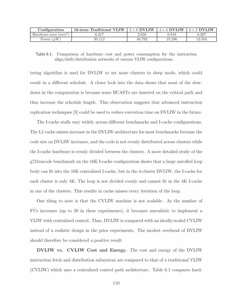
Configuration 16-issue Traditional VLIW 2 × 8 DVLIW 4 × 4 DVLIW 8 × 2 DVLIW
Hardware area (mm2) 6.317 2.638 0.843 0.307Power (µW ) 95.112 46.792 25.296 12.504
Table 6.1: Comparison of hardware cost and power consumption for the instructionalign/shift/distribution networks of various VLIW configurations.
tering algorithm is used for DVLIW to set more clusters to sleep mode, which could
result in a different schedule. A closer look into the data shows that most of the slow-
down in the computation is because some BCASTs are inserted on the critical path and
thus increase the schedule length. This observation suggests that advanced instruction
replication techniques [3] could be used to reduce execution time on DVLIW in the future.
The I-cache stalls vary widely across different benchmarks and I-cache configurations.
The L1 cache misses increase in the DVLIW architecture for most benchmarks because the
code size on DVLIW increases, and the code is not evenly distributed across clusters while
the I-cache hardware is evenly divided between the clusters. A more detailed study of the
g721encode benchmark on the 16K I-cache configuration shows that a large unrolled loop
body can fit into the 16K centralized I-cache, but in the 4-cluster DVLIW, the I-cache for
each cluster is only 4K. The loop is not divided evenly and cannot fit in the 4K I-cache
in one of the clusters. This results in cache misses every iteration of the loop.
One thing to note is that the CVLIW machine is not scalable. As the number of
FUs increases (up to 20 in these experiments), it becomes unrealistic to implement a
VLIW with centralized control. Thus, DVLIW is compared with an ideally-scaled CVLIW
instead of a realistic design in the prior experiments. The modest overhead of DVLIW
should therefore be considered a positive result.
DVLIW vs. CVLIW Cost and Energy. The cost and energy of the DVLIW
instruction fetch and distribution subsystem are compared to that of a traditional VLIW
(CVLIW) which uses a centralized control path architecture. Table 6.1 compares hard-
110

1
10
100
1000
10000
100000
1000000
raw
caudio
raw
daudio
g721encode
g721decode
gsm
encode
gsm
decode
epic
unepic
pegw
itdec
pegw
itenc
rasta
cjp
eg
djp
eg
mpeg2enc
mpeg2dec
164.g
zip
256.b
zip
2
181.m
cf
197.p
ars
er
255.v
ort
ex
300.t
wolf
avera
ge
Tra
ffic
Rati
oIcmove
Fetch
Total
Figure 6.3: Reduction in dynamic global communication signals of a 4-cluster DVLIWprocessor.
ware cost and power consumption of the instruction align/distribution logic for DVLIW
and CVLIW. The issue width of all configurations is 16 and the TINKER encoding is
assumed [14]. To employ compressed encodings, shift, align, and distribution networks
are required in both CVLIW and DVLIW. The shift/align network is required because the
beginning of variable-length instructions will not always be aligned to the beginning of a
cache line. A distribution network is required because the control bits must be delivered
to all the FUs but the positions of control bits for FUs are not fixed. The cost of these
networks increase quadratically with the issue width, because the number of MUXes and
the number of inputs for each MUX increase with the issue width. Using the Synop-
sys Design Compiler, we synthesized the major components of these networks. As can
be seen from the table, the distributed organization of the DVLIW can effectively con-
trol this quadratic cost and energy consumption of the alignment and distribution logic.
111

0
0.2
0.4
0.6
0.8
1
1.2
1.4
raw
ca
ud
io
raw
da
ud
io
g7
21
en
co
de
g7
21
de
co
de
gsm
en
co
de
gsm
de
co
de
ep
ic
un
ep
ic
pe
gw
itd
ec
pe
gw
ite
nc
rasta
cjp
eg
djp
eg
mp
eg
2e
nc
mp
eg
2d
ec
16
4.g
zip
25
6.b
zip
2
18
1.m
cf
19
7.p
ars
er
25
5.v
ort
ex
30
0.tw
olf
ave
rag
e
Re
lati
ve
En
erg
y C
on
su
mp
tio
nalign/distribution wires cache total
Figure 6.4: Relative energy consumption for the instruction fetch subsystem of a 4-clusterDVLIW processor.
By distributing the networks, a large centralized network can be avoided for wider issue
machines.
The key benefit of DVLIW is that most instruction fetch and distribution can be
done locally. Only rarely is global distribution of control bits necessary. For purposes
of this analysis, we define a global signal as an inter-cluster transfer or transfer between
a centralized memory and a cluster. A local signal is one that is contained within a
cluster (possibly including a local I- or D-cache.) Figure 6.3 compares the number of
bytes distributed globally on a 4-cluster DVLIW and CVLIW. Three bars are shown
for each benchmark. The first bar shows the increase in inter-cluster data communica-
tion on DVLIW architectures, including BCASTs and WAKEs; this increase is generally
negligible. The second bar shows the ratio of globally distributed instruction bytes on
the CVLIW to globally distributed instruction bytes on DVLIW. On the CVLIW with
112

1
1.2
1.4
1.6
1.8
2
raw
ca
ud
io
raw
da
ud
io
g7
21
en
co
de
g7
21
de
co
de
gsm
en
co
de
gsm
de
co
de
ep
ic
un
ep
ic
pe
gw
itd
ec
pe
gw
ite
nc
rasta
cjp
eg
djp
eg
mp
eg
2e
nc
mp
eg
2d
ec
16
4.g
zip
25
6.b
zip
2
18
1.m
cf
19
7.p
ars
er
25
5.v
ort
ex
30
0.tw
olf
ave
rag
e
Re
lati
ve
Co
de
Siz
e
No sleep
Sleep
Figure 6.5: Effectiveness of sleep mode on a 4-cluster DVLIW.
centralized I-fetch, all the instruction bits need to be distributed on global wires (both
L1 hits and misses), while on DVLIW, only L1 cache misses need to be transferred on
global wires. The ratio varies from 20 to 1,000,000 across the benchmarks. The third bar
shows the total reduction of global traffic including both inter-cluster move and instruc-
tion fetch. The total ratio is not as large as the fetch ratio because inter-cluster data
transfers represent a significant portion of the global traffic that does not change much
on DVLIW.
The reduction in global traffic combined with a more efficient cache organization leads
to potential energy savings for DVLIW over a traditional VLIW. Focusing on the in-
struction fetch subsystem, Figure 6.4 reports the relative energy on a 4 cluster DVLIW
architecture. A value of 1 in the figure is the instruction fetch energy consumption on a
CVLIW processor with the same issue width and centralized control path. Our instruc-
tion energy consumption model consists of 3 parts: align/distribution, interconnect, and
the L1/L2 caches. The align/distribution energy was presented previously in Table 6.1.
113
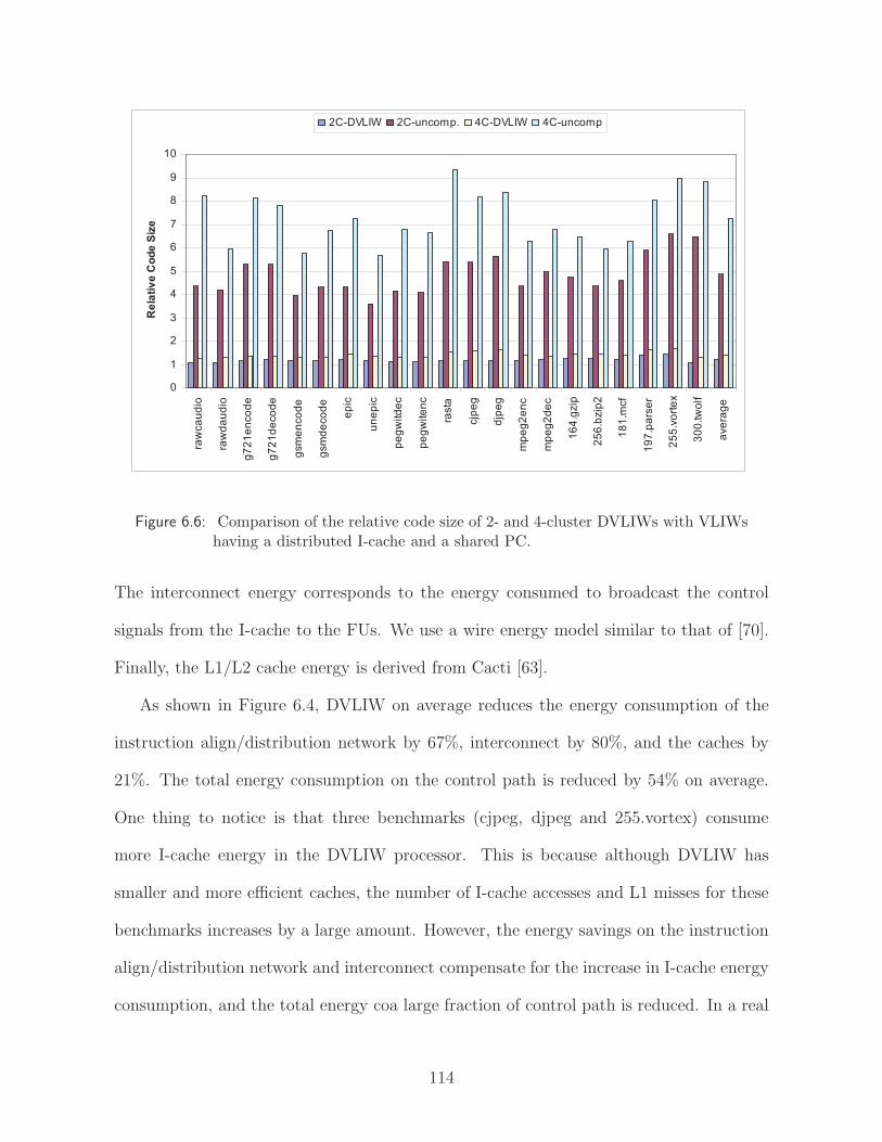
0
1
2
3
4
5
6
7
8
9
10
raw
ca
ud
io
raw
da
ud
io
g7
21
en
co
de
g7
21
de
co
de
gsm
en
co
de
gsm
de
co
de
ep
ic
un
ep
ic
pe
gw
itd
ec
pe
gw
ite
nc
rasta
cjp
eg
djp
eg
mp
eg
2e
nc
mp
eg
2d
ec
16
4.g
zip
25
6.b
zip
2
18
1.m
cf
19
7.p
ars
er
25
5.v
ort
ex
30
0.tw
olf
ave
rag
e
Re
lati
ve
Co
de
Siz
e
2C-DVLIW 2C-uncomp. 4C-DVLIW 4C-uncomp
Figure 6.6: Comparison of the relative code size of 2- and 4-cluster DVLIWs with VLIWshaving a distributed I-cache and a shared PC.
The interconnect energy corresponds to the energy consumed to broadcast the control
signals from the I-cache to the FUs. We use a wire energy model similar to that of [70].
Finally, the L1/L2 cache energy is derived from Cacti [63].
As shown in Figure 6.4, DVLIW on average reduces the energy consumption of the
instruction align/distribution network by 67%, interconnect by 80%, and the caches by
21%. The total energy consumption on the control path is reduced by 54% on average.
One thing to notice is that three benchmarks (cjpeg, djpeg and 255.vortex) consume
more I-cache energy in the DVLIW processor. This is because although DVLIW has
smaller and more efficient caches, the number of I-cache accesses and L1 misses for these
benchmarks increases by a large amount. However, the energy savings on the instruction
align/distribution network and interconnect compensate for the increase in I-cache energy
consumption, and the total energy coa large fraction of control path is reduced. In a real
114

0
0.2
0.4
0.6
0.8
1
1.2
raw
ca
ud
io
raw
da
ud
io
g7
21
en
co
de
g7
21
de
co
de
gsm
en
co
de
gsm
de
co
de
ep
ic
un
ep
ic
pe
gw
itd
ec
pe
gw
ite
nc
rasta
cjp
eg
djp
eg
mp
eg
2d
ec
16
4.g
zip
25
6.b
zip
2
18
1.m
cf
19
7.p
ars
er
30
0.tw
olf
ave
rag
e
Rela
tive C
yc
les
on
DV
LIW
stall cycles
execution time
Figure 6.7: Comparison of the relative stall cycles and execution time on a 4-clusterDVLIW with a VLIW having a distributed I-cache and a shared PC.
processor, instruction fetch consumes a large fraction of power dissipated by the processor.
For example, instruction consumes 27% of CPU power in the StrongARM SA-100 [18],
and almost 50% of CPU power in the Motorola MCORE [38]. The energy savings on the
control path translate to a significant power reduction for the whole chip.
DVLIW Sleep Mode. To demonstrate the effectiveness of sleep mode in reducing
code size, Figure 6.5 compares the relative code size with and without sleep mode enabled
for a 4-cluster DVLIW machine. The code size is reported relative to the 4-cluster CVLIW
with a fully compressed encoding. On average, DVLIW code size decreases from 1.77 times
that of a CVLIW without sleep mode to 1.40 when sleep mode is used. This shows that
in parts of the application that do not have high ILP, significant code size and energy
savings can be realized by turning off unused clusters.
DVLIW vs. Distributed Uncompressed Instruction Memory. The obvious
115

alternative to DVLIW is to distribute the control path, but with a single PC, similar
to the Multiflow TRACE system as shown in Figure 3.5(c). With this approach, code
compression cannot be employed as discussed in Section 2. Figure 6.6 compares the
normalized code size of DVLIW and the distributed uncompressed architecture. On the
y-axis, a value of 1 is the code size of the benchmark on a CVLIW machine with a fully
compressed encoding. Again, the TINKER encoding is assumed in our experiments [14].
Four bars are presented for each benchmark. The first bar is the normalized code size of
the benchmark on the 2-cluster DVLIW machine. The second bar shows the normalized
code size on a 2-cluster distributed machine with uncompressed encoding. The third
and fourth bars show corresponding data for 4-cluster configurations. On average, the
normalized code size is 1.2 on the 2-cluster DVLIW and 1.4 on the 4-cluster DVLIW.
The increase in code size on DVLIW is due to the introduction of EPBRs, BCASTs,
EBRs, WAKEs and other related operations such as spill code. As stated before, the
fully uncompressed encoding must be used for distributed architectures with a shared PC
or multiple identical PCs. As shown in the figure, the code size on DVLIW machines is
much smaller than the code size on those machines.
Figure 6.7 shows the relative stalls and execution cycles of a 4-cluster DVLIW over
the corresponding processors with uncompressed distributed I-cache. The datapath of
both machines is identical. The TINKER encoding is used for DVLIW, while the shared
PC machine uses an uncompressed encoding. As shown in the figure, on average, stall
cycles decrease by 70% on DVLIW and consequently, the total execution time reduced
by 30%. One benchmark 164.gzip is slightly slower on DVLIW because the I-cache stalls
account for a small fraction of the total execution time, and the overhead incurred by
extra operations on DVLIW outweighs the benefit of fewer I-cache stalls. However, for
the majority of benchmarks, the benefits of smaller code size and fewer I-cache misses
116
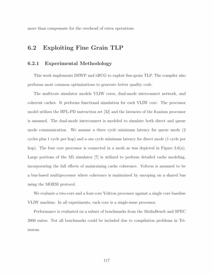
more than compensate for the overhead of extra operations.
6.2 Exploiting Fine Grain TLP
6.2.1 Experimental Methodology
This work implements DSWP and eBUG to exploit fine-grain TLP. The compiler also
performs most common optimizations to generate better quality code.
The multicore simulator models VLIW cores, dual-mode interconnect network, and
coherent caches. It performs functional simulation for each VLIW core. The processor
model utilizes the HPL-PD instruction set [32] and the latencies of the Itanium processor
is assumed. The dual-mode interconnect is modeled to simulate both direct and queue
mode communication. We assume a three cycle minimum latency for queue mode (2
cycles plus 1 cycle per hop) and a one cycle minimum latency for direct mode (1 cycle per
hop). The four core processor is connected in a mesh as was depicted in Figure 3.6(a).
Large portions of the M5 simulator [7] is utilized to perform detailed cache modeling,
incorporating the full effects of maintaining cache coherence. Voltron is assumed to be
a bus-based multiprocessor where coherence is maintained by snooping on a shared bus
using the MOESI protocol.
We evaluate a two-core and a four-core Voltron processor against a single core baseline
VLIW machine. In all experiments, each core is a single-issue processor.
Performance is evaluated on a subset of benchmarks from the MediaBench and SPEC
2000 suites. Not all benchmarks could be included due to compilation problems in Tri-
maran.
117
0.90
1.00
1.10
1.20
1.30
1.40
1.50
1.60
1.70
132.ijp
eg
164.g
zip
171.s
wim
172.m
grid
175.v
pr
177.m
esa
179.a
rt
183.e
quake
197.p
ars
er
256.b
zip
2
300.t
wolf
cjp
eg
djp
eg
epic
g721decode
g721encode
gsm
decode
gsm
encode
mpeg2dec
mpeg2enc
pegw
itdec
pegw
itenc
raw
caudio
raw
daudio
unepic
avera
ge
2 core 4 core
Figure 6.8: Speedup for fine-grain TLP execution.
6.2.2 Results
Figure 6.8 shows the speedup of TLP execution on 2 core and 4 core systems. Again,
the baseline, 1.0 in the figure, represents the execution time of benchmarks on a single-
core processor. The eBUG algorithm is used to partition operation to multiple cores.
Our compiler inserts communications and insure the correct memory access ordering.
As shown in the figure, on average, a 1.09x speedup is achieved on the 2 core system
and a 1.14x speedup is achieved on the 4 core system. Since eBUG extracts fine-grain
from individual basic blocks or hyperblocks. The speedup that can be achieve is closely
related to the amount of parallelism within the block. Because the decoupled execution
mode has a higher communication latency, the fine-grain TLP execution can have a lower
118

0.0
0.1
0.2
0.3
0.4
0.5
0.6
0.7
0.8
0.9
1.0
052.a
lvin
n
056.e
ar
132.ijp
eg
164.g
zip
171.s
wim
172.m
grid
175.v
pr
177.m
esa
179.a
rt
183.e
quake
197.p
ars
er
255.v
ort
ex
256.b
zip
2
cjp
eg
djp
eg
epic
g721decode
g721encode
gsm
decode
gsm
encode
mpeg2dec
mpeg2enc
raw
caudio
raw
daudio
unepic
call return sync
predicate recv
recv stall
D-stalls
I-stalls
Figure 6.9: Breakdown of synchronization stalls by type on a 4-core system. Each bench-mark has two bars: the left bar is for decoupled mode and the right for coupledmode.
speedup compared to ILP execution. However, if the application has many cache misses,
decoupled execution has the benefit of being able to overlap undeterministic latencies.
Benchmarks that have a lot cache misses, such as 179.art, performs better in fine-grain
TLP execution than ILP execution. Note that there are room to improve the performance
of TLP execution through a better compiler algorithm. The compiler algorithm can
examine scopes larger than a single block to expose more parallelism. That’s one direction
of my future work.
Memory and communication stalls. Figure 6.9 shows the relative execution time
each benchmark spends on stalls under coupled and decoupled mode when executing on
a 4-core Voltron processor. Stall cycles are normalized to the total execution time of the
benchmark under coupled mode. Two bars are shown for each benchmark. The first bar
shows the average stall cycles for all 4 cores in decoupled mode, and the second shows
119

the stall cycles in coupled mode. Every bar in the graph has several parts representing
the reasons the cores can stall. The bottom-most two parts of each bar show the average
stalls due to instruction and data cache misses. For decoupled mode, they are followed by
stalls due to receive instructions and synchronization before function calls and returns.
The receive stalls are further separated into data receives and predicate receives to study
how much stalling is caused by control synchronization.
As the data indicates, decoupled mode always spends less time on cache miss stalls
because different cores are allowed to stall separately. On average, the number of stall
cycles under decoupled mode is less than half of that under coupled mode. This explains
why it is beneficial to execute memory intensive benchmarks in decoupled mode. How-
ever, decoupled mode suffers from extra stalls due to scalar communication and explicit
synchronization, which hurts the performance if such communication and synchronization
is frequent.
6.3 Uncovering Hidden LLP
6.3.1 Methodology
We implemented the algorithms discussed in the previous section in the OpenIMPACT
compiler [54]. The algorithms identify opportunities for control dependence speculation
(DOALL-uncounted loops), register reduction variable expansion, long distance memory
dependence iteration chunking, speculative loop fission, speculative prematerialization,
and infrequent dependence isolation. For reduction variable expansion, the compiler iden-
tifies reduction variables for summation, production, logical AND/OR/XOR, as well as
variables for finding min/max. For speculative loop fission, the compiler identifies loops
where the sequential part represents less than 3% of the dynamic execution of the loop. For
120
infrequent dependence isolation, the frequency of cross iteration register dependence and
library calls has to be less than 10%. For long distance memory dependences, a threshold
of 4 iterations is assumed. These thresholds were experimentally chosen to maximize the
speedup. Several benchmarks from SPEC CPU 92/95/2000, MediaBench [37], and Unix
utilities are studied and we show the results for all the benchmarks that successfully ran
through our system.
Our multicore simulation system models 1-8 single-issue in-order processor cores sim-
ilar to the ARM-9. The simulator models a scalar operand network, where we assume
a 3 cycle latency to communicate register values between neighboring cores. A perfect
memory system is assumed. We use a software transactional memory [17] to emulate the
underlying hardware transactional memory described in Section 3.3. We assume that the
transaction abort incurs an average of 500 cycles overhead and requires execution of the
reset block as well as re-execution of the chunk. Successfully committed transactions do
not incur extra overhead besides XBEGIN and XCOMMIT instructions.
6.3.2 Results
Figure 6.10 shows the fraction of the dynamic sequential execution that can be par-
allelized after applying all our proposed transformation techniques. On average, 61% of
the sequential execution can be speculatively parallelized. This number is more than
twice the coverage of 28% using TLS without any transformation, and 8.5 times the 7%
gain by relying on static analysis alone (see Figure 5.1). More importantly, for SPECint
benchmarks, the transformations are able to uncover loop level parallelism in 55% of the
sequential execution, where previous techniques yield poor results.
Figure 6.11 shows the speedups achieved on 2-core, 4-core and 8-core machines com-
pared to a single core. One stacked bar is shown for each configuration. The lower part
121

0.0
0.1
0.2
0.3
0.4
0.5
0.6
0.7
0.8
0.9
1.0
052.a
lvin
n
056.e
ar
171.s
wim
172.m
grid
177.m
esa
179.a
rt
183.e
quake
188.a
mm
p008.e
spre
sso
023.e
qnto
tt026.c
om
pre
ss
072.s
c
099.g
o124.m
88ksim
129.c
om
pre
ss
130.li
132.ijp
eg
164.g
zip
175.v
pr
181.m
cf
197.p
ars
er
256.b
zip
2
300.t
wolf
cjp
eg
djp
eg
epic
g721decode
g721encode
gsm
decode
gsm
encode
mpeg2dec
mpeg2enc
pegw
itdec
pegw
itenc
raw
caudio
raw
daudio
unepic
gre
ple
x
yacc
avera
ge
SPEC FP SPEC INT Mediabench Utilities
Fra
ction o
f sequential execution
Figure 6.10: Fraction of sequential execution covered by speculative DOALL loops aftertransformations
shows the speedup results without our proposed transformations. Therefore, only counted
loops with no or very few cross iteration dependences from profiling are parallelized. The
higher part of the stack bar shows the speedup after all transformations are applied. The
compiler chooses the most profitable loop to parallelize if multiple nesting levels can be
parallelized.
On average, we achieved a speedup of 1.36 with transformations compared to the 1.19
speedup without transformation on a 2-core machine. In addition, we got much higher
speedups on 4-core and 8-core configurations as the average speedup increases from 1.41
to 1.84 for the 4-core machine and from 1.63 to 2.34 for the 8-core machine after applying
transformations.
The speedup values vary widely across different benchmarks. For SPECfp bench-
marks, significant speedup values are achieved due to the inherent parallel nature of the
122

1
1.5
2
2.5
3
3.5
4
4.5
5
5.5
6
052.a
lvin
n
056.e
ar
171.s
wim
172.m
gri
d
177.m
esa
179.a
rt
183.e
quake
188.a
mm
p
008.e
spre
sso
023.e
qnto
tt
026.c
om
pre
ss
072.s
c
099.g
o
124.m
88ksim
129.c
om
pre
ss
130.li
132.ijp
eg
164.g
zip
175.v
pr
181.m
cf
197.p
ars
er
256.b
zip
2
300.t
wolf
cjp
eg
djp
eg
epic
g721decode
g721encode
gsm
decode
gsm
encode
mpeg2dec
mpeg2enc
pegw
itdec
pegw
itenc
raw
caudio
raw
daudio
unepic
gre
p
lex
yacc
avera
ge
SPEC FP SPEC INT Mediabench Utilities
Speedup
Without transformations With transformations
7.897.37
7.87
6.44
8 cores
2 cores
4 cores
Figure 6.11: Effect of the compiler transformations on performance for 2, 4, and 8 coresystems. The bottom portion of each bar shows the baseline with TLS onlyand the top portion shows the combined affects of all transformations.
applications. In the SPECint benchmarks, the average speedups are 1.19, 1.37 and 1.50
for 2-core, 4-core and 8-core configurations, which is a considerable improvement over
previous techniques. As shown in the figure, the baseline compiler cannot extract much
parallelism from these benchmarks due to the large number of inter-iteration register and
control dependences typically found in C applications.
The speedups for MediaBench benchmarks are generally higher than SPECint, while
the Unix utility benchmarks have similar results to SPECint. If we consider reduction
variable expansion as part of the baseline, the speedups without transformations increase
to an average of 1.24, 1.59 and 1.95, respectively. Our new transformations still achieve
considerable speedups on top of that. It should also be noted that reduction variable ex-
pansion helped mostly in the SPECfp benchmarks compared to the integer applications.
The new transformations are especially helpful for SPECint benchmarks where traditional
transformations alone are largely unsuccessful. Note that high coverages shown in Fig-
ure 6.10 do not always translate to high speedup numbers. Mpeg2enc is an example of
123

1
1.5
2
2.5
3
3.5
4
052.a
lvin
n
056.e
ar
171.s
wim
172.m
gri
d
177.m
esa
179.a
rt
183.e
quake
188.a
mm
p008.e
spre
sso
023.e
qnto
tt026.c
om
pre
ss
072.s
c099.g
o124.m
88ksim
129.c
om
pre
ss
130.li
132.ijp
eg
164.g
zip
175.v
pr
181.m
cf
197.p
ars
er
256.b
zip
2300.t
wolf
cjp
eg
djp
eg
epic
g721decode
g721encode
gsm
decode
gsm
encode
mpeg2dec
mpeg2enc
pegw
itdec
pegw
itenc
raw
caudio
raw
daudio
unepic
gre
ple
xyacc
avera
ge
SPEC FP SPEC INT Mediabench Utilities
Speedup
Inter-core communication through
memory system
Inter-core communication through
scalar operand network
No parallelization overhead
Figure 6.12: The first two bars show the effect of inter-core communication through mem-ory systems versus scalar operand network. The last bar shows the speedupwithout any parallelization overhead.
such a case. The loops identified as parallel in this example have a small loop body and
low trip count. Therefore, the parallelization overhead makes it much less appealing for
parallelizing such loops. Another observation is that the SPECfp benchmarks are quite
scalable. Several benchmarks such as 171.swim, 172.mgrid and 179.art achieve almost
linear speedup on 4 and 8 cores.
As mentioned before, we use Scalar Operand Network (SON) to communicate register
values between the cores and maintain commit orderings. In Figure 6.12, we studied
the effects of SON and also the code generation framework on the benchmark speedups.
This figure shows the speedup values on a 4-core machine with different configurations.
Three bars are shown for each benchmark. The first bar shows the speedup assuming we
don’t have a scalar operand network and all communications between the cores must go
124

through the shared L2 cache. In this scheme, the commit order is maintained using locking
primitives. We assume communication between cores takes 30 cycles. The second bar
shows the case when we have a SON can communicate register values between neighboring
cores with a 3-cycle latency. This is the same data from Figure 6.11. As shown in the
figure, for some benchmarks such as 171.swim, 179.art and 175.vpr, we can achieve nearly
the same speedup with and without the SON. These benchmarks have large loop bodies
with high trip counts, and the communication overhead is amortized by large chunks of
parallel work. On the other hand, benchmarks, such as pegwitdec, pegwitenc, and grep,
suffer significantly from lack of the SON. The loop sizes in these benchmarks are small to
medium, and the high communication overhead easily takes away all the benefits resulting
from parallelization. On average, the speedup without the SON is 1.70 compared to the
1.85x speedup with the SON. We can see that a reasonable benefit can be achieved from
the transformations without a SON as well. The third bar in Figure 6.12 shows speedups
without the parallelization overhead. Our speculative parallelization framework decreases
the performance gain by about 10% on average compared to the configuration with zero
parallelization overhead.
Table 6.2 shows the the fraction of the dynamic sequential execution that can be par-
allelized with different techniques. It also shows the abort frequencies during speculative
execution. The first 7 columns show the coverage of different transformation techniques.
Each element represents the time spent in loops that are parallelized by a certain trans-
formation. For example, by applying reduction variable expansion in 052.alvinn, loops
that account for 97% of the sequential execution time can become parallelizable. For the
transformation in each column, we assume the techniques in columns to the left have been
applied, so the data in a column represents the additional parallelism being uncovered.
If both the outer and inner loop in a nested loop are parallelized by a certain technique,
125

Bench DOALL CS RE SF PM IDI LD AFSpecFP
052.alvinn 55 0 97 94 0 0 0 0056.ear 99 0 0 0 0 0 0 0171.swim 98 0 2 98 0 0 0 0172.mgrid 98 0 0 97 0 0 0 0177.mesa 68 0 6 0 0 0 0 0179.art 51 0 77 100 94 77 0 0183.equake 66 0 41 16 0 44 0 0188.ammp 10 16 0 1 0 0 0 0
SpecINT008.espresso 8 12 18 9 25 3 22 2023.eqntott 2 95 0 30 0 1 97 0026.compress 1 0 0 29 0 0 0 0072.sc 1 3 14 5 0 24 0 0099.go 4 2 0 8 0 3 1 1124.m88ksim 15 1 0 34 0 34 0 0129.compress 2 0 9 4 0 0 0 0130.li 0 0 0 17 0 0 44 1132.ijpeg 60 19 1 16 9 26 0 0164.gzip 9 0 0 2 0 0 0 1175.vpr 0 0 0 79 0 0 100 0181.mcf 1 1 0 42 0 0 1 2197.parser 12 0 2 6 0 0 1 1255.vortex 0 0 0 0 0 0 0 0256.bzip2 5 1 0 100 0 0 49 2300.twolf 1 0 0 54 0 2 1 0
MediaBenchcjpeg 53 0 2 9 0 6 0 0djpeg 29 23 23 59 23 0 0 1epic 86 0 87 85 0 0 1 0g721decode 8 0 36 0 0 0 0 0g721encode 7 0 34 0 0 0 0 0gsmdecode 12 3 0 0 0 0 0 0gsmencode 12 2 47 0 0 1 0 0mpeg2dec 92 5 67 5 0 3 0 0mpeg2enc 13 84 33 31 10 0 0 0pegwitdec 26 0 0 31 0 0 0 0pegwitenc 28 0 0 32 0 0 0 0rawcaudio 0 0 0 0 0 0 0 0rawdaudio 0 0 0 0 0 0 0 0unepic 41 0 10 12 0 0 0 0
Utilitiesgrep 0 43 0 0 0 0 0 0lex 21 5 0 70 0 2 0 0yacc 33 52 17 2 0 3 20 6
average 27 9 15 28 4 5 8 0
Table 6.2: Percentage sequential code coverage of various transformations – Last columnshows the Abort frequencies in the benchmarks. Coverages higher than 20%are highlighted. (CS:control speculation for uncounted loop, RE: reductionexpansion, SF: speculative fission, PM: prematerialization, IDI: infrequent de-pendence isolation, LD: ignore long distance dependence, AF: abort frequency).
126

only the time spent in the outer loop taken into account. If the outer and inner loop are
parallelized by two different techniques, the time spent in the inner loop will show up in
two categories. Therefore, the numbers in a row could add up to more than 100%.
The first column shows the coverage of parallel loops without any transformations. The
second column shows the fraction of time spent in DOALL-uncounted loops. On average,
control flow speculation alone enables an additional 9% of the sequential execution to
execute in parallel. Moreover, it is an enabling technique for other transformations. For
example, infrequent dependence isolation converts a loop into a nested loop, and the inner
one is DOALL-uncounted. The third column is for register reduction variable expansion.
On average, it converts 15% of the execution into parallel loops. This is a relatively simple
transformation and provides good performance improvement. For any system that tries
to parallelize sequential programs, reduction variable expansion should be the first low
hanging fruit to go for.
The next column shows fraction of time spent in loops that can be parallelized by
speculative loop fission. On average, it enables 28% of the execution to partially execute
in parallel. This transformation has the largest potential among the ones that we studied.
It is especially useful for SPECint benchmarks for which other techniques do not provide
much benefit.
Prematerialization, infrequent dependence isolation, and iteration chunking for long
distance memory dependence each improve parallel coverage significantly for certain bench-
marks. In contrast to control speculation, reduction expansion and fission, they each affect
less than 50% of the benchmarks. However, in the benchmarks which they show benefits,
it is usually quite significant. On average, they improve the parallel coverage by 4%, 5%
and 8%, respectively.
The last column in the table shows the abort frequency during speculative execution.
127

The abort frequency is the number of aborted iterations divided by the total number of
iterations in the benchmark. As shown in the figure, they are quite low, and most bench-
marks have abort frequencies less than 2%. We also studied the stability of the profile
results on different inputs. We found loops without cross iteration memory dependence
on one input usually do not have cross iteration memory dependence using other inputs as
well. As a result, speculative DOALL loops are mostly consistent across different inputs.
6.4 Exploiting Hybrid Parallelism
6.4.1 Experimental Methodology
The compiler implements techniques to exploit ILP, fine-grain TLP and statistical LLP
described in Chapter 4 and Chapter 5. For each basic block in the program, the compiler
selects the best type of parallelism to exploit to achieve the best speedup. The compiler
first looks for opportunities to exploit loop level parallelism. The algorithm in Section 5.4
is used to selected profitable loops to parallelize. Loops are parallelized first because
they provide the most efficient parallelism; neither communication nor synchronization
is needed between cores for the parallel execution of the loop body. For blocks that are
not in a parallel loop, the compiler applies the partitioning algorithm for ILP and TLP
separately, the execution mode with higher estimated performance gain is selected.
This section evaluates two-core and four-core Voltron processors against a single core
baseline VLIW machine. We assume there is no overhead to switch between different
execution modes for this study.
128
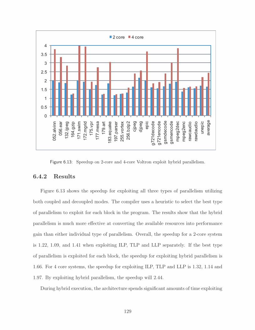
0
0.5
1
1.5
2
2.5
3
3.5
4
052.a
lvin
n
056.e
ar
132.ijp
eg
164.g
zip
171.s
wim
172.m
grid
175.v
pr
177.m
esa
179.a
rt
183.e
quake
197.p
ars
er
255.v
ort
ex
256.b
zip
2
cjp
eg
djp
eg
ep
ic
g721d
eco
de
g721enco
de
gsm
deco
de
gsm
enco
de
mp
eg
2d
ec
mp
eg
2enc
raw
caud
io
raw
daud
io
unep
ic
avera
ge
2 core 4 core
Figure 6.13: Speedup on 2-core and 4-core Voltron exploit hybrid parallelism.
6.4.2 Results
Figure 6.13 shows the speedup for exploiting all three types of parallelism utilizing
both coupled and decoupled modes. The compiler uses a heuristic to select the best type
of parallelism to exploit for each block in the program. The results show that the hybrid
parallelism is much more effective at converting the available resources into performance
gain than either individual type of parallelism. Overall, the speedup for a 2-core system
is 1.22, 1.09, and 1.41 when exploiting ILP, TLP and LLP separately. If the best type
of parallelism is exploited for each block, the speedup for exploiting hybrid parallelism is
1.66. For 4 core systems, the speedup for exploiting ILP, TLP and LLP is 1.32, 1.14 and
1.97. By exploiting hybrid parallelism, the speedup will 2.44.
During hybrid execution, the architecture spends significant amounts of time exploiting
129

0%
10%
20%
30%
40%
50%
60%
70%
80%
90%
100%
052.a
lvin
n
056.e
ar
132.ijp
eg
164.g
zip
171.s
wim
172.m
grid
175.v
pr
177.m
esa
179.a
rt
183.e
quake
197.p
ars
er
255.v
ort
ex
256.b
zip
2
cjp
eg
djp
eg
ep
ic
g721d
eco
de
g721enco
de
gsm
deco
de
gsm
enco
de
mp
eg
2d
ec
mp
eg
2enc
raw
caud
io
raw
daud
io
unep
ic
avera
ge
ILP fine-grain TLP LLP single core
Figure 6.14: Breakdown of sequential execution time best accelerated by exploiting dif-ferent types of parallelism.
different types of parallelism. Figure 6.14 shows the percentage of sequential execution
time spent exploiting ILP, TLP, LLP or executing on a single core. This experiment
assumes a 4-core system. This figure shows that there is no dominant type of parallelism,
and the contribution of each form of parallelism varies widely across the benchmarks. On
average, the fraction of dynamic execution that is attributed to each form of parallelism
is: 54% by LLP, 19% by fine-grain TLP, and 23% by ILP. 4% of the execution doesn’t
show any opportunities for all three types of parallelism as it had the highest performance
on a single core.
This figure is similar to Figure 2.5 in Chapter 2. The difference is that the experiment
conducted for Figure 2.5 does not apply the LLP uncovering transformations proposed in
Chapter 5. After applying the transformations, more loops can be parallelized and more
130

execution time are spent exploiting LLP. However, as shown in the figure, ILP and TLP
are still important source of performance improvement and they need to be exploited
when coarse grain parallelism are not available.
131
CHAPTER 7
Summary
The micorprocessor industry is gradually shifting from single-core to multicore sys-
tems. A major challenge going forward is to get the software to utilize the vast amount of
computing power and adapt single thread applications to keep up with this advancement.
This dissertation proposed architectural and compiler mechanisms to automatically ac-
celerate single thread application on multiple systems by efficiently exploiting three types
of parallelism: instruction level parallelism(ILP), find-grain thread level parallelism(TLP)
and speculative loop level parallelism(LLP).
First, this dissertation proposed a multicore architecture, called DVLIW, to exploit
ILP across multiple cores. DVLIW allows multiple in-order cores to dynamically coa-
lesce into a wide VLIW processor. Compiler manages multiple instruction streams to
collectively function as a single logical stream on a conventional VLIW. A synchronized
branch mechanism is proposed to facilitate the collective execution. The same techniques
in DVLIW can also be applied to decentralize the control path in conventional VLIW
processors to improve the scalability and reduce energy consumption. The scalability
and energy savings are achieved without sacrificing the code size benefits of compressed
instruction encodings.
132

Second, this dissertation proposes a multicore architecture, referred to as Voltron,
that is designed to exploit the hybrid forms of parallelism that can be extracted from
general-purpose applications. The unique aspect of Voltron is the ability to operate in
one of two modes: coupled and decoupled. In coupled mode, the cores execute in lock-
step forming a wide-issue VLIW processor. Each core executes its own instruction stream
and through compiler orchestration, the streams collectively execute a single thread. In
decoupled mode, the cores operate independently on fine-grain threads created by the
compiler. Coupled mode offers the advantage of fast inter-core communication and the
ability to efficiently exploit ILP across the cores. Decoupled mode offers the advantage
of fast synchronization and the ability to overlap execution across loop iterations and in
code regions with frequent cache misses.
Finally, this dissertation studied the automatic parallelization of loops in general-
purpose applications with TLS hardware support. By studying the benchmarks, I found
that a considerable amount of loop-level parallelism is buried beneath the surface. This
work adapted and introduced several code transformations to expose the hidden paral-
lelism in single-threaded applications. More specifically, I introduced speculative loop
fission, isolation of infrequent dependences, and speculative prematerialization to untan-
gle cross iteration data dependences, and a general code generation framework to handle
both counted and uncounted speculative DOALL loops. With the new transformation
techniques, more than 61% of dynamic execution time in the general applications can
be parallelized compared to 27% achieved using traditional techniques. On a 4-core ma-
chine, our transformations achieved 1.84x speedup compared to 1.41x speedup without
transformations.
133

BIBLIOGRAPHY
134

BIBLIOGRAPHY
[1] S. Aditya, S. Mahlke, and B. Rau. Code size minimization and retargetable assemblyfor custom EPIC and VLIW instruction formats. ACM Transactions on DesignAutomation of Electronic Systems, 5(4):752–773, 2000.
[2] V. Agarwal, M. S. Hrishikesh, S. W. Keckler, and D. Burger. Clock rate versus ipc:The end of the road for conventional microarchitecture. In Proc. of the 27th AnnualInternational Symposium on Computer Architecture, pages 248 – 259, June 2000.
[3] Alex Aleta, Josep M. Codina, Antonio Gonzalez, and David Kaeli. Instruction repli-cation for clustered microarchitectures. In Proc. of the 36th Annual InternationalSymposium on Microarchitecture, page 326, 2003.
[4] R. Allen and K. Kennedy. Optimizing compilers for modern architectures: Adependence-based approach. Morgan Kaufmann Publishers Inc., 2002.
[5] C. Scott Ananian, Krste Asanovic, Bradley C. Kuszmaul, Charles E. Leiserson, andSean Lie. Unbounded transactional memory. In Proc. of the 11th InternationalSymposium on High-Performance Computer Architecture, pages 316–327, February2005.
[6] A. Bhowmik and M. Franklin. A general compiler framework for speculative multi-threading. In SPAA ’02: 14th Annual ACM Symposium on Parallel Algorithms andArchitectures, pages 99–108, 2002.
[7] N. L. Binkert, E. G. Hallnor, and S. K. Reinhardt. Network-oriented full-systemsimulation using M5. In 6th Workshop on Computer Architecture Evaluation usingCommercial Workloads, pages 36–43, February 2003.
[8] W. Blume et al. Parallel programming with Polaris. IEEE Computer, 29(12):78–82,December 1996.
[9] Michael K. Chen and Kunle Olukotun. Exploiting method-level parallelism in single-threaded Java programs. In Proc. of the 7th International Conference on ParallelArchitectures and Compilation Techniques, page 176, October 1998.
[10] Michael K. Chen and Kunle Olukotun. The Jrpm system for dynamically parallelizingJava programs. In Proc. of the 30th Annual International Symposium on ComputerArchitecture, pages 434–446, 2003.
135
[11] Peng-Sheng Chen, Ming-Yu Hung, Yuan-Shin Hwang, Roy Dz-Ching Ju, andJenq Kuen Lee. Compiler support for speculative multithreading architecture withprobabilistic points-to analysis. In Proc. of the 8th ACM SIGPLAN Symposium onPrinciples and Practice of Parallel Programming, pages 25–36, June 2003.
[12] M. Chu, K. Fan, and S. Mahlke. Region-based hierarchical operation partitioning formulticluster processors. In Proc. of the SIGPLAN ’03 Conference on ProgrammingLanguage Design and Implementation, pages 300–311, June 2003.
[13] R. Colwell et al. Architecture and implementation of a VLIW supercomputer. InProc. of the 1990 International Conference on Supercomputing, pages 910–919, June1990.
[14] T. Conte et al. Instruction fetch mechanisms for VLIW architectures with compressedencodings. In Proc. of the 29th Annual International Symposium on Microarchitec-ture, pages 201–211, December 1996.
[15] K. Cooper et al. The ParaScope parallel programming environment. Proceedings ofthe IEEE, 81(2):244–263, February 1993.
[16] Daivd E. Culler, Jaswinder Pal Singh, and Anoop Gupta. Parallel Computer Archi-tecture, A Hardware/Software Approach. Morgan Kaufmann, 1996.
[17] Dave Dice, Ori Shalev, and Nir Shavit. Transactional Locking II. In Proc. of the2006 International Symposium on Distributed Computing, 2006.
[18] D. Dobberpuhl. The design of a high-performance low-power microprocessor. InProc. of the 1996 International Symposium on Low Power Electronics and Design,pages 11–16, 1996.
[19] Zhao-Hui Du et al. A cost-driven compilation framework for speculative paralleliza-tion of sequential programs. In Proc. of the SIGPLAN ’04 Conference on Program-ming Language Design and Implementation, pages 71–81, 2004.
[20] Jan Elder and Mark D. Hill. Dinero IV trace-driven uniprocessor cache simulator,2003.
[21] J.R. Ellis. Bulldog: A Compiler for VLIW Architectures. MIT Press, Cambridge,MA, 1985.
[22] Marco Fillo, Stephen W. Keckler, William J. Dally, Nicholas P. Carter, AndrewChang, Yevgeny Gurevich, and Whay S. Lee. The m-machine multicomputer. InProc. of the 28th Annual International Symposium on Microarchitecture, pages 146–156. IEEE Computer Society Press, 1995.
[23] J. Fisher. Very Long Instruction Word Architectures and the ELI-52. In Proc. ofthe 10th Annual International Symposium on Computer Architecture, pages 140–150,1983.
136

[24] E. Gibert, J. Sanchez, and A. Gonzalez. An interleaved cache clustered VLIW pro-cessor. In Proc. of the 2002 International Conference on Supercomputing, pages210–219, June 2002.
[25] E. Gibert, J. Sanchez, and A. Gonzalez. Flexible compiler-managed L0 buffers forclustered VLIW processors. In Proc. of the 36th Annual International Symposiumon Microarchitecture, pages 315–325, December 2003.
[26] M. Hall et al. Maximizing multiprocessor performance with the SUIF compiler. IEEEComputer, 29(12):84–89, December 1996.
[27] Lance Hammond, Mark Willey, and Kunle Olukotun. Data speculation support fora chip multiprocessor. In Eighth International Conference on Architectural Supportfor Programming Languages and Operating Systems, pages 58–69, October 1998.
[28] Lance Hammond, Vicky Wong, Mike Chen, Brian D. Carlstrom, John D. Davis, BenHertzberg, Manohar K. Prabhu, Honggo Wijaya, Christos Kozyrakis, and KunleOlukotun. Transactional memory coherence and consistency. In Proc. of the 31stAnnual International Symposium on Computer Architecture, page 102, June 2004.
[29] Maurice Herlihy and J. Eliot B. Moss. Transactional memory: Architectural supportfor lock-free data structures. In Proc. of the 20th Annual International Symposiumon Computer Architecture, pages 289–300, May 1993.
[30] Engin Ipek, Meyrem Kirman, Nevin Kirman, and Jose F. Martinez. Core fusion: ac-commodating software diversity in chip multiprocessors. In Proc. of the 34th AnnualInternational Symposium on Computer Architecture, pages 186–197, 2007.
[31] T. A. Johnson, R. Eigenmann, and T. N. Vijaykumar. Min-cut program decom-position for thread-level speculation. In Proc. of the SIGPLAN ’04 Conference onProgramming Language Design and Implementation, pages 59–70, June 2004.
[32] Vinod Kathail, Mike Schlansker, and Bob Rau. HPL-PD architecture specifica-tion: Version 1.1. Technical Report HPL-93-80(R.1), Hewlett-Packard Laboratories,February 2000.
[33] H. Kim and J. Smith. An instruction set and microarchitecture for instruction leveldistributed processing. In Proc. of the 29th Annual International Symposium onComputer Architecture, pages 71–81, June 2002.
[34] Michael Kozuch and Andrew Wolfe. Compression of embedded system programs.pages 270–277, 1994.
[35] D. J. Kuck. The Structure of Computers and Computations. John Wiley and Sons,New York, NY, 1978.
[36] S. Larin and T. Conte. Compiler-driven cached code compression schemes for em-bedded ILP processors. In Proc. of the 32nd Annual International Symposium onMicroarchitecture, pages 82–92, November 1999.
137

[37] C. Lee, M. Potkonjak, and W.H. Mangione-Smith. MediaBench: A tool for evaluatingand synthesizing multimedia and communications systems. In Proc. of the 30thAnnual International Symposium on Microarchitecture, pages 330–335, 1997.
[38] L. Lee et al. Low-Cost Embedded Program Loop Caching - Revisited. TechnicalReport CSE-TR-411-99, Univ. of Michigan, October 1999.
[39] Sunah Lee and Rajiv Gupta. Executing loops on a fine-grained MIMD architecture.In Proc. of the 24th Annual International Symposium on Microarchitecture, pages199–205, 1991.
[40] Rainer Leupers. Code Optimization Techniques for Embedded Processors - Methods,Algorithms, and Tools. Kluwer Academic Publishers, Boston, MA, 2000.
[41] S. Liao et al. Instruction selection using binate covering for code size optimization.In Proc. of the 1995 International Conference on Computer Aided Design, pages393–399, 1995.
[42] Wei Liu et al. POSH: A TLS compiler that exploits program structure. In Proc.of the 11th ACM SIGPLAN Symposium on Principles and Practice of Parallel Pro-gramming, pages 158–167, April 2006.
[43] S. A. Mahlke, D. C. Lin, W. Y. Chen, R. E. Hank, and R. A. Bringmann. Effectivecompiler support for predicated execution using the hyperblock. In Proc. of the 25thAnnual International Symposium on Microarchitecture, pages 45–54, December 1992.
[44] P. Marcuello and A. Gonzalez. Thread-spawning schemes for speculative multithread-ing. In Proc. of the 8th International Symposium on High-Performance ComputerArchitecture, page 55, February 2002.
[45] D. Matzke. Will physical scalability sabotage performance gains. IEEE Computer,30(9):37–39, September 1997.
[46] Avi Mendelson, Julius Mandelblat, Simcha Gochman, Anat Shemer, RajshreeChabukswar, Erik Niemeyer, and Arun Kumar. CMP implementation insystems based on the Intel Core Duo processor. Intel Technology Journal,10(2):http://www.intel.com/technology/itj/2006/volume10issue02/, 2006.
[47] Chi Cao Minh, Martin Trautmann, JaeWoong Chung, Austen McDonald, NathanBronson, Jared Casper, Christos Kozyrakis, and Kunle Olukotun. An effective hybridtransactional memory system with strong isolation guarantees. In Proc. of the 34thAnnual International Symposium on Computer Architecture, pages 69–80, 2007.
[48] Sungdo Moon, Byoungro So, and Mary W. Hall. Evaluating automatic parallelizationin SUIF. Journal of Parallel and Distributed Computing, 11(1):36–49, 2000.
[49] Kevin E. Moore, Jayaram Bobba, Michelle J. Moravan, Mark D. Hill, and David A.Wood. LogTM: Log-based transactional memory. In Proc. of the 12th InternationalSymposium on High-Performance Computer Architecture, pages 254–265, February2006.
138
[50] C. Newburn, A. Huang, and J. Shen. Balancing fine- and medium-grained parallelismin scheduling loops for the XIMD architecture. In Proc. of the 2nd InternationalConference on Parallel Architectures and Compilation Techniques, pages 39–52, 1993.
[51] Michael D. Noakes, Deborah A. Wallach, and William J. Dally. The j-machinemulticomputer: an architectural evaluation. In Proc. of the 20th Annual InternationalSymposium on Computer Architecture, pages 224–235. ACM Press, 1993.
[52] E. Nystrom and A. E. Eichenberger. Effective cluster assignment for modulo schedul-ing. In Proc. of the 31st Annual International Symposium on Microarchitecture, pages103–114, December 1998.
[53] E. Nystrom, H-S Kim, and W. Hwu. Bottom-up and top-down context-sensitivesummary-based pointer analysis. In Proc. of the 11th Static Analysis Symposium,pages 165–180, August 2004.
[54] OpenIMPACT. The OpenIMPACT IA-64 compiler, 2005. http://gelato.uiuc.edu/.
[55] Jeffrey Oplinger, David Heine, Shih-Wei Liao, Basem A. Nayfeh, Monica S. Lam, andKunle Olukotun. Software and hardware for exploiting speculative parallelism witha multiprocessor. Technical Report CSL-TR-97-715, Stanford University, February1997.
[56] Guilherme Ottoni, Ram Rangan, Adam Stoler, and David I. August. Automaticthread extraction with decoupled software pipelining. In Proc. of the 38th AnnualInternational Symposium on Microarchitecture, pages 105–118, November 2005.
[57] E. Ozer, S. Banerjia, and T. Conte. Unified assign and schedule: A new approach toscheduling for clustered register file microarchitectures. In Proc. of the 31st AnnualInternational Symposium on Microarchitecture, pages 308–315, December 1998.
[58] M. Prabhu and K. Olukotun. Exposing speculative thread parallelism in SPEC2000.In Proc. of the 10th ACM SIGPLAN Symposium on Principles and Practice of Par-allel Programming, pages 142–152, June 2005.
[59] Carlos Garcia Quinones et al. Mitosis compiler: an infrastructure for speculativethreading based on pre-computation slices. In Proc. of the SIGPLAN ’05 Conferenceon Programming Language Design and Implementation, pages 269–279, June 2005.
[60] Ravi Rajwar and James R. Goodman. Transactional lock-free execution of lock-based programs. In Tenth International Conference on Architectural Support forProgramming Languages and Operating Systems, pages 5–17, October 2002.
[61] B. R. Rau, D. W. L. Yen, and R. A. Towle. The cydra 5 departmental supercomputer.IEEE Computer, 1(22):12–34, January 1989.
[62] L. Rauchwerger and D. A. Padua. The LRPD test: Speculative run-time paralleliza-tion of loops with privatization and reduction parallelization. IEEE Transactions onParallel and Distributed Systems, 10(2):160, 1999.
139

[63] G. Reinman and N. P. Jouppi. Cacti 2.0: An integrated cache timing and powermodel. Technical Report WRL-2000-7, Hewlett-Packard Laboratories, February2000.
[64] J. Sanchez and A. Gonzalez. Modulo scheduling for a fully-distributed clusteredVLIW architecture. In Proc. of the 33rd Annual International Symposium on Mi-croarchitecture, pages 124–133, December 2000.
[65] K. Sankaralingam, R. Nagarajan, H. Liu, J. Huh, C.K. Kim, D. Burger, S.W. Keckler,and C.R. Moore. Exploiting ILP, TLP, and DLP using polymorphism in the TRIPSarchitecture. In Proc. of the 30th Annual International Symposium on ComputerArchitecture, pages 422–433, June 2003.
[66] Michael S. Schlansker, Scott A. Mahlke, and Richard Johnson. Control CPR: Abranch height reduction optimization for EPIC architectures. In Proc. of the SIG-PLAN ’99 Conference on Programming Language Design and Implementation, pages155–168, May 1999.
[67] Gurindar S. Sohi, Scott E. Breach, and T. N. Vijaykumar. Multiscalar processors. InProc. of the 22nd Annual International Symposium on Computer Architecture, pages414–425, June 1995.
[68] J. Greggory Steffan and Todd C. Mowry. The potential for using thread-level dataspeculation to facilitate automatic parallelization. In Proc. of the 4th InternationalSymposium on High-Performance Computer Architecture, pages 2–13, 1998.
[69] J. Gregory Steffan, Christopher Colohan, Antonia Zhai, and Todd C. Mowry. TheSTAMPede approach to thread-level speculation. ACM Transactions on ComputerSystems, 23(3):253–300, 2005.
[70] Clark N. Taylor, Sujit Dey, and Yi Zhao. Modeling and minimization of interconnectenergy dissipation in nanometer technologies. In Proc. of the 38th Design AutomationConference, pages 754–757. ACM Press, 2001.
[71] M. Taylor et al. Evaluation of the Raw microprocessor: An exposed-wire-delay archi-tecture for ILP and streams. In Proc. of the 31st Annual International Symposiumon Computer Architecture, pages 2–13, June 2004.
[72] M. Taylor, W. Lee, S. Amarasinghe, and A. Agarwal. Scalar operand networks:On-chip interconnect for ILP in partitioned architectures. In Proc. of the 9th Inter-national Symposium on High-Performance Computer Architecture, pages 341–353,February 2003.
[73] Trimaran. An infrastructure for research in ILP, 2000. http://www.trimaran.org/.
[74] J. Tsai et al. The superthreaded processor architecture. IEEE Transactions onComputers, 48(9):881–902, September 1999.
140

[75] Neil Vachharajani, Ram Rangan, Easwaran Raman, Matthew Bridges, GuilhermeOttoni, and David August. Speculative Decoupled Software Pipelining. In Proc. of the16th International Conference on Parallel Architectures and Compilation Techniques,pages 49–59, September 2007.
[76] T. N. Vijaykumar and Gurindar S. Sohi. Task selection for a multiscalar processor.In Proc. of the 31st Annual International Symposium on Microarchitecture, pages81–92, December 1998.
[77] H. Wang, L. Peh, and S. Malik. Power-driven design of router microarchitectures inon-chip networks. In Proc. of the 36th Annual International Symposium on Microar-chitecture, pages 105–114, December 2003.
[78] A. Wolfe and J. Shen. A variable instruction stream extension to the VLIW architec-ture. In Fourth International Conference on Architectural Support for ProgrammingLanguages and Operating Systems, pages 2–14, October 1991.
[79] Yuan Xie and Wayne Wolf. Allocation and scheduling of conditional task graph inhardware/software co-synthesis. In Proc. of the 2001 Design, Automation and Testin Europe, pages 620–625, December 2001.
[80] Luke Yen et al. LogTM-SE: Decoupling hardware transactional memory from caches.In Proc. of the 13th International Symposium on High-Performance Computer Ar-chitecture, pages 261–272, February 2007.
[81] Hongtao Zhong, Kevin Fan, Scott Mahlke, and Mike Schlansker. A distributed controlpath architecture for VLIW processors. In Proc. of the 14th International Conferenceon Parallel Architectures and Compilation Techniques, pages 197–206, September2005.
[82] Hongtao Zhong, Steve Lieberman, and Scott Mahlke. Extending multicore architec-tures to exploit hybrid parallelism in single-thread applications. In Proc. of the 13thInternational Symposium on High-Performance Computer Architecture, pages 25–36,February 2007.
[83] Hongtao Zhong, Mojtaba Mehrara, Steve Lieberman, and Scott Mahlke. Uncoveringhidden loop level parallelism in sequential applications. In Proc. of the 14th Inter-national Symposium on High-Performance Computer Architecture, page to appear,February 2008.
[84] C. Zilles and G. Sohi. Master/slave speculative parallelization. In Proc. of the 35thAnnual International Symposium on Microarchitecture, pages 85–96, November 2002.
141