arc behavior and droplet dynamics of ac gtaw-gmaw hybrid ... · gas tungsten arc welding (gtaw) and...
TRANSCRIPT
WELDING RESEARCH
MARCH 2018 / WELDING JOURNAL 91-s
Introduction
Gas tungsten arc welding (GTAW)and gas metal arc welding (GMAW) arethe most popular gas-shielded arcwelding techniques used in many in-dustrial fields. Traditional GTAW is ahigh-quality process that features lessspatters and better weld bead surfacesthan GMAW. However, GTAW suffersfrom slow speed and small amounts ofdeposited metal. Different methods,such as hot-wire GTAW (Ref. 1), acti-vated-GTAW (Ref. 2), double-sidedGTAW (Ref. 3), and twin-tungstenGTAW (Ref. 4), have been developed toobtain better deposition rates. On theother hand, GMAW is a process with
high rates of metal deposition, but in-creased heat input into the base metal(Ref. 5). As a consequence, the GTAW-GMAW hybrid welding process has be-come a new type of arc weldingprocess combining the high quality ofGTAW with the high efficiency ofGMAW. Kanemaru et al. (Refs. 6, 7) experi-mentally and numerically studied thebalance of current between gas tung-sten and gas metal arcs in GTAW-GMAW hybrid welding. A suitablerange of currents was confirmed. Chenet al. (Ref. 8) analyzed distributions ofheat flux and weld formation, and pro-posed energy-force models to study in-teracting forces between gas tungsten
and gas metal arcs in GTAW-GMAWhybrid welding. Tao et al. (Ref. 9) fur-ther studied the properties of hybridarc, transition modes of droplets, andinfluence of different polarity con-nected to the weld joint. The GTAW-GMAW hybrid arc could be superim-posed in parallel gas tungsten and gasmetal arcs. Similar to traditional arcwelding, welding current is still from aconsumable electrode or tungsten elec-trode to base metal through whichheat input cannot be reduced effec-tively. Y. M. Zhang proposed a double-electrode-GMAW and arcing wireGTAW (Refs. 10, 11) in which a thirdconsumable or nonconsumable elec-trode was added, and thus a bypass arcwas introduced burning between itand the original wire or tungsten elec-trode. As a result, the total currentflowing through the wire and the basemetal could be separately controlled;in other words, the wire depositionrate and the heat input to the basemetal were separately controlled ordeeply decoupled. Wang et al. (Ref. 12) studied theconsumable-aided tungsten indirectarc welding with direct current (DC).An indirect arc was generated betweenthe consumable electrode of theGMAW gun and tungsten electrode ofthe GTAW torch, whereas it was ab-sent between the tungsten or consum-able electrode of welding torch andbase metal. Welding current flowedfrom the consumable electrode totungsten electrode in the freeburningindirect arc. Consumable-aided tung-sten indirect arc welding not only rap-idly melted the welding wire but also
Arc Behavior and Droplet Dynamics of AC GTAW-GMAW Hybrid Indirect Arc
The effects of the AC waveform parameters, and the position of the wire and tungsten electrodes on the arc behavior and droplet dynamics, were studied
S. J. CHEN, L. W. WANG, J. XIAO, AND P. S. WEI
ABSTRACT The alternating current (AC) gas tungsten arc welding-gas metal arc welding(GTAW-GMAW) hybrid indirect arc process is characterized by the arcconfiguration in which the AC flows between the filling wire and tungstenelectrode but not the base metal. In this study, the effects of the square ACwaveform parameters and the relative position of the wire and tungstenelectrodes on the arc behavior and droplet dynamics were studied. Observationsshowed that the arc configuration between the tungsten electrode and wire onthe wire-negative stage was in a curved cylinder shape, accompanied by cathodespot climbing along the droplet and wire surface, and the droplet swings towardthe tungsten side. When the polarity of the wire was changed from cathode toanode, the arc configuration changed into a triangle profile. The droplet began toswing toward the wire side. The transport direction of the droplet was along theline connecting the tungsten electrode tip and wire tip. The results showed theeffects of current frequency on the maximum climbing height of cathode spot.The cathode spot movement was also scaled, which is related to spread ofcurrent into the droplet.
KEYWORDS • GTAW-GMAW Hybrid Indirect Arc • Cathode Spot • Droplet Dynamic • Arc Behavior • Cathode Spot Motion
https://doi.org/10.29391/2018.97.008
Chen corrected (201757)_Layout 1 2/9/18 3:16 PM Page 91
WELDING RESEARCH
WELDING JOURNAL / MARCH 2018, VOL. 9792-s
effectively restrained heat input intothe base metal. The consumable elec-trode connected to the positive pole ofwelding power is the arc anode. It wasfound that the consumable electrodeacting as the cathode had a highermelting rate than the anode (Refs. 13,14). By comparison to tungsten-con-sumable indirect arc welding (TCIAW)with DC, AC TCIAW has a higher depo-sition rate, as also verified by theoreti-cal analysis (Ref. 14). In contrast to base metal as an arcterminal in conventional arc welding,arc terminals of tungsten and wire tipin TCIAW are comparatively small insize and allowed flexible variations.The alternative polarity between tung-sten and wire tips in AC TCIAW alsoplays an important role in sustainingthe arc between the two tips. Arc be-havior and droplet transfer have animportant effect on heat input, depo-sition rates, and weld forming. Under-standing the different parameters af-fecting arc behavior and droplet trans-fer of AC TCIAW is essentially requiredfor a practical use of the promisingwelding technology. Defects such as porosity, weldcracking, or entrainment of an oxidelayer into the weld pool occur if the ox-ide layer remains on a weld pool sur-face in arc welding. The oxide film onthe surface of the base material can beremoved through the cleaning actionof the cathode spot, when the elec-trode is positive and the base materialacts as a cathode (Ref. 15). Whether
the motion is random or directed de-pends on a self-induced and externalimposed magnetic field (Ref. 16). Thebehavior or motion of the cathodespot is thus directly linked to currentdistribution in arc plasma and stronglyaffects the detachment of the dropleton the wire tip. In this paper, experiments wereconducted on the effects of magnitudeand frequency of welding current, rela-tive location of the wire, and the tung-sten tip on arc behavior and droplettransfer. Understanding and control-ling arc behavior, cathode spot, anddroplet transport are required for dif-ferent kinds of arc welding processes.
Experiment Setup
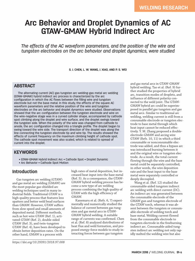
The measurement system is com-posed of the following: welding powersource, wire feeder, high-speed cam-era, current and voltage sensors, dataacquisition, and control systems, assketched in Fig. 1. The tungsten andwire, respectively, were connected withthe two electrodes of the welding pow-er supply. The arc was burning be-tween the tungsten and wire with AC .No current flowed to the base metal.The AC power source and wire feederwere both program-controlled. The ar-gon shielding gas had a flow rate of 15L/min. An IDT Motion Pro Y-4 high-speed camera was used to capture thearc and droplet dynamics. The ER70S-6 wire had a diameter of 1.2 mm,whereas the tungsten electrode had a
diameter of 5.0 mm. The current am-plitudes of the AC square wave were80, 100, 120, 140, and 160 A. The ACfrequencies varied in four levels: 25,50, 100, 200, and 400 Hz. The initial relative positions be-tween the tungsten and wire tip beforearc ignition were categorized to fourconfigurations: wire at upper right,right side, lower right, and below, asshown in Fig. 2. The initial distancebetween two tips was 3 mm in the hor-izontal direction. With a given weldingcurrent, the arc between the tungstenand wire electrode was ignited by wayof short circuit.
Results and Discussion
The recorded waveforms of currentand voltage showed good periodicityand repeatability, which verified theexpected stability of indirect arc andcurrent waveform.
Cathode Spot Motion
In Tests 1–5, the welding currentwas fixed at 100 A. Current alternat-ing frequency of the square wave in-creased from 25, 50, 100, and 200 to400 Hz. The time ratio of positive andnegative half-wave was 1:1 (tungsten-positive/wire-negative stage is definedas positive-half-wave). The remainingtest parameters are shown in Table 1. Figure 3 shows time-dependentcurrent and voltage with positive and
Fig. 1 — Experimental setup. Fig. 2 — Initial relative positions of tungsten and wire.
Chen corrected (201757)_Layout 1 2/9/18 3:16 PM Page 92
WELDING RESEARCH
MARCH 2018 / WELDING JOURNAL 93-s
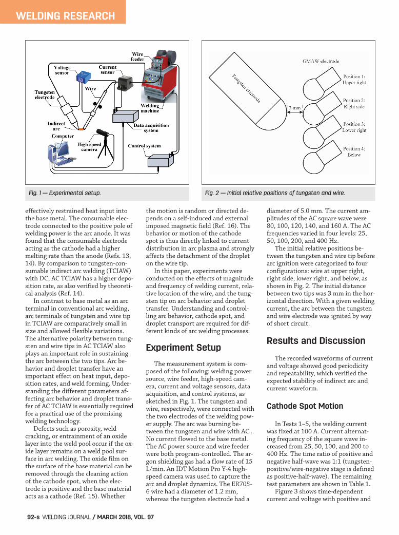
negative half-waves during the indi-rect arc burning process (see Test 3). Itcan be seen that duration of positiveand negative half-wave is 5 ms in eachcycle, respectively, corresponding to asquare current frequency of 100 Hz.The current was stable at about 100 A.The voltage of positive half-wave wasmaintained between 18 and 22 V,whereas the voltage of negative half-wave showed a gradual increase trendfrom 21 to 29 V. A sudden decline oc-curred near the end of each cycle be-cause when the wire is cathode, thecathode spot automatically searchesfor the oxide film and climbs along thewire. In view of the cathode spotclimbing, the voltage of the indirectarc rose as the arc length increased.The upward motion of the cathodespot has been attributed to the pres-sure difference across the cathode spot(Ref. 16). Pressure difference acrossthe cathode spot, considering thesame order of magnitude as electro-magnetic force, was found to be pro-portional to the products of externalmagnetic field and self-magnetic field.Electric current was then scaled by a
self-magnetic field and external mag-netic field, satisfied by Ampere’s lawand Lorentz’s force law. The resultantforce thus resulted in an upward mo-tion of the cathode spot. However, in this study, it is difficultto exclusively specify the externalmagnetic field due to the complex arcdynamics, thereby, an alternative andsimpler interpretation by using scaleanalysis was proposed. Fluid flowequation in the arc beyond the dropletwas given by (Ref. 16)
where variables a,Vr', jn', and B' aredensity, radial velocity, axial currentdensity, and azimuthal self-inducedmagnetic field in arc, respectively. Equation 1 indicates that the pincheffect takes place in the arc ahead ofthe droplet, as a result of negative ve-locity in the radial direction. Currentspreads after entering the cathodespot, as illustrated in Fig. 4. Fluidequation in the droplet yield
where d is density of the droplet, sub-scripts s and r are, respectively, the di-rection parallel to the droplet surfaceand radial direction in the droplet. Since current is spread in thedroplet, Equation 2 indicates that liq-uid velocity in the droplet increases forpositive current density in the radialdirection. Ampere’s law related toEquation 2 is
Scaling Equations 2 and 3 gives
where I is the welding current. Equation 4, therefore, shows thecathode spot moved upward as a resultof a spread of electric current in thedroplet. Spot velocity increased linear-ly with magnetic field agreed with pre-
�aVr'dVr'dr'
= � jn'B�' (1)
�dVsdVsds
= jrB� (2)
� �B��s
=μd jr (3)
Vs � B� � jr � I (4)
Fig. 3 — Recorded current and voltage waveforms in Test 3. Fig. 4 — Schematic of current distribution and electromagneticforce at the spot.
Table 1 — Test Parameters for Different Current Frequencies
Test No. Current Current Wire Feed Relative Location Amplitude (A) Frequency (Hz) Speed Between Tungsten (m/min) and Wire Tip
1 100 25 3.2 Right side 2 100 50 3.2 Right side 3 100 100 3.2 Right side 4 100 200 3.2 Right side 5 100 400 3.2 Right side
Chen corrected (201757)_Layout 1 2/9/18 3:16 PM Page 93
WELDING RESEARCH
WELDING JOURNAL / MARCH 2018, VOL. 9794-s
vious measurements (Refs. 17–19)and arc current (Ref. 19).
The Effects of CurrentFrequency on Arc Behaviorand Droplet Dynamics
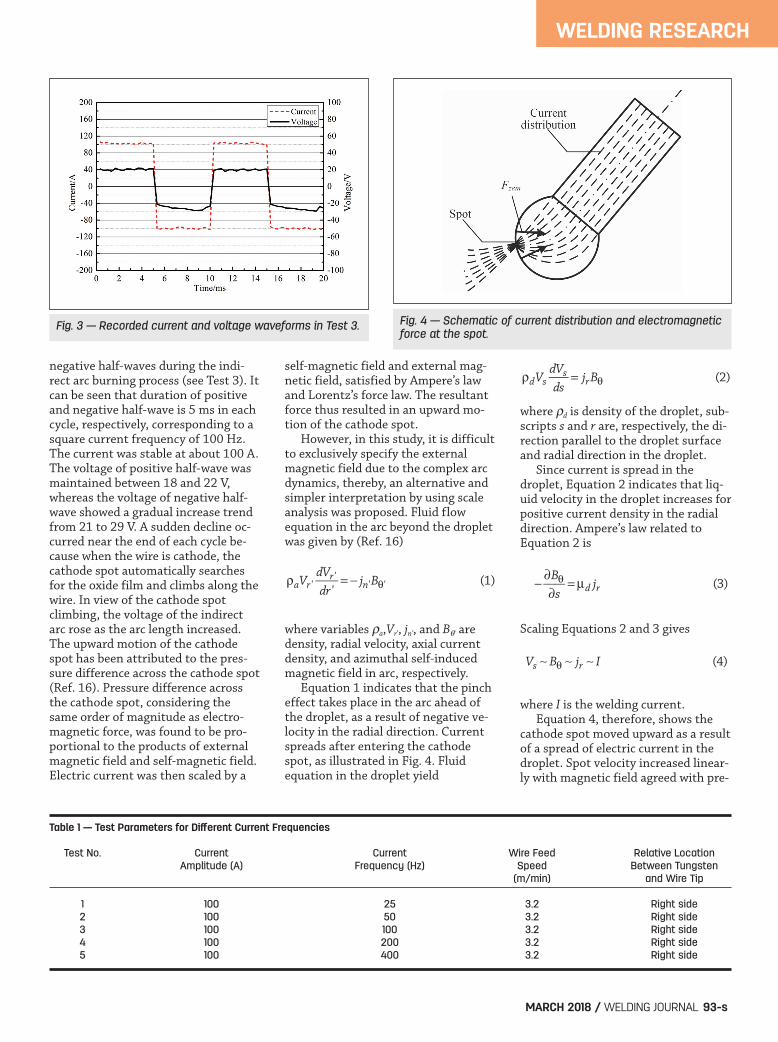
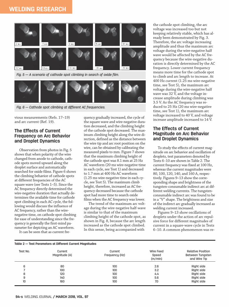
Observation from photos in Fig. 5shows that when polarity of the wirechanged from anode to cathode, cath-ode spots moved upward along thedroplet surface and automaticallysearched for oxide films. Figure 6 showsthe climbing behavior of cathode spotsat different frequencies of the ACsquare wave (see Tests 1–5). Since theAC frequency directly determined thewire-negative duration that actually de-termines the available time for cathodespot climbing in each AC cycle, the fol-lowing would discuss the influence ofAC frequency, rather than the wire-negative time, on cathode spot climbingfor ease of understanding since the fre-quency is generally the first-mind pa-rameter for depicting an AC waveform. It can be seen that as current fre-
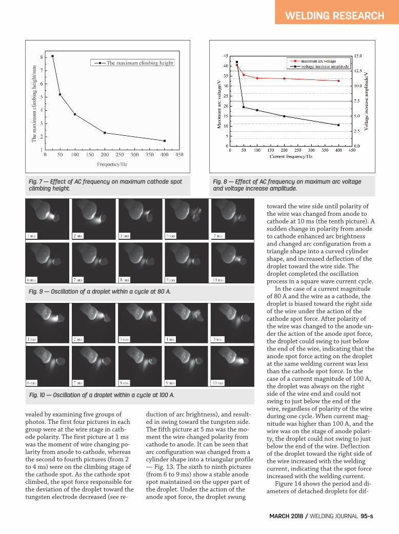
quency gradually increased, the cycle ofthe square wave and wire-negative dura-tion decreased, and the climbing heightof the cathode spot decreased. The max-imum climbing height along the wire di-rection, defined as the distance betweenthe wire tip and arc root position on thewire, can be obtained by calibrating themeasured pixels to mm. Figure 7 showsthat the maximum climbing height ofthe cathode spot was 8.1 mm at 25 HzAC waveform (20 ms wire-negative timein each cycle, see Test 1) and decreasedto 1.7 mm at 400 Hz AC waveform(1.25 ms wire-negative time in each cy-cle, see Test 5). The maximum climbheight, therefore, increased as AC fre-quency decreased because the cathodespot had more time to search oxidefilms when the AC frequency was lower. The trend of the maximum arc volt-age during the wire-negative half-waveis similar to that of the maximumclimbing height of the cathode spot, asshown in Fig. 8, because the arc lengthincreased as the cathode spot climbed.In this sense, being accompanied with
the cathode spot climbing, the arcvoltage was increased too but notkeeping relatively stable, which has al-ready been demonstrated by Fig. 3.Therefore, the arc voltage increasingamplitude and thus the maximum arcvoltage during the wire-negative halfwave would be affected by the AC fre-quency because the wire-negative du-ration is directly determined by the ACfrequency. Lower current frequencymeans more time for the cathode spotto climb and arc length to increase. At400 Hz current (1.25 ms wire-negativetime, see Test 5), the maximum arcvoltage during the wire-negative halfwave was 32 V, and the voltage in-crease amplitude during climbing was3.5 V. As the AC frequency was re-duced to 25 Hz (20 ms wire-negativetime, see Test 1), the maximum arcvoltage increased to 40 V, and voltageincrease amplitude increased to 14 V.
The Effects of Current Magnitude on Arc Behaviorand Droplet Dynamics
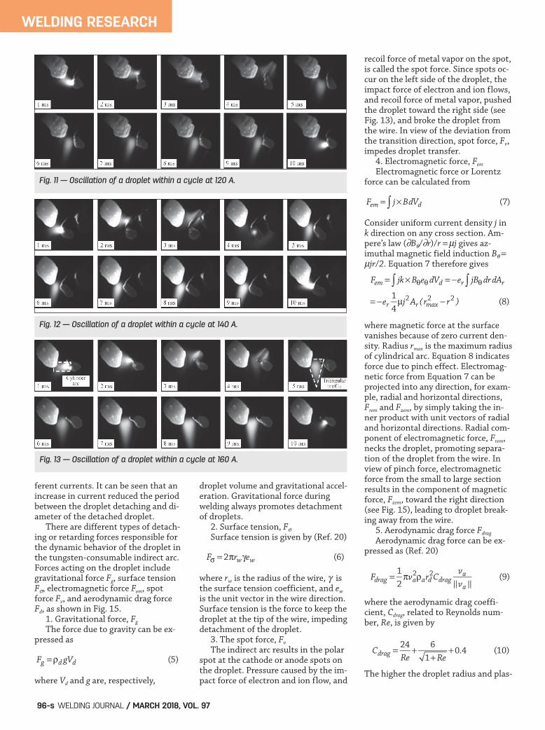
To study the effects of current mag-nitude on arc behavior and oscillation ofdroplets, test parameters denoted byTests 6–10 are shown in Table 2. Thecurrent frequency was fixed at 100 Hz,whereas the current magnitudes were80, 100, 120, 140, and 160 A, respec-tively. Figures 9–13 show the corre-sponding shape and brightness of thetungsten-consumable indirect arc at dif-ferent welding currents. The tungsten-consumable indirect arc was found to bein a “V” shape. The brightness and sizeof the indirect arc gradually increased aswelding current increased. Figures 9–13 show oscillations ofdroplets under the action of arc repul-sive force for different magnitudes ofcurrent in a square-wave cycle in Tests6–10. A common phenomenon was re-
Fig. 5 — A scenario of cathode spot climbing in search of oxide film.
Fig. 6 — Cathode spot climbing at different AC frequencies.
Table 2 — Test Parameters at Different Current Magnitudes
Test No. Current Current Wire Feed Relative Position Magnitude (A) Frequency (Hz) Speed Between Tungsten (m/min) and Wire Tip
6 80 100 2.6 Right side 7 100 100 3.2 Right side 8 120 100 4.4 Right side 9 140 100 5.6 Right side 10 160 100 7.0 Right side
Chen corrected (201757)_Layout 1 2/9/18 3:16 PM Page 94
WELDING RESEARCH
MARCH 2018 / WELDING JOURNAL 95-s
vealed by examining five groups ofphotos. The first four pictures in eachgroup were at the wire stage in cath-ode polarity. The first picture at 1 mswas the moment of wire changing po-larity from anode to cathode, whereasthe second to fourth pictures (from 2to 4 ms) were on the climbing stage ofthe cathode spot. As the cathode spotclimbed, the spot force responsible forthe deviation of the droplet toward thetungsten electrode decreased (see re-
duction of arc brightness), and result-ed in swing toward the tungsten side.The fifth picture at 5 ms was the mo-ment the wire changed polarity fromcathode to anode. It can be seen thatarc configuration was changed from acylinder shape into a triangular profile— Fig. 13. The sixth to ninth pictures(from 6 to 9 ms) show a stable anodespot maintained on the upper part ofthe droplet. Under the action of theanode spot force, the droplet swung
toward the wire side until polarity ofthe wire was changed from anode tocathode at 10 ms (the tenth picture). Asudden change in polarity from anodeto cathode enhanced arc brightnessand changed arc configuration from atriangle shape into a curved cylindershape, and increased deflection of thedroplet toward the wire side. Thedroplet completed the oscillationprocess in a square wave current cycle. In the case of a current magnitudeof 80 A and the wire as a cathode, thedroplet is biased toward the right sideof the wire under the action of thecathode spot force. After polarity ofthe wire was changed to the anode un-der the action of the anode spot force,the droplet could swing to just belowthe end of the wire, indicating that theanode spot force acting on the dropletat the same welding current was lessthan the cathode spot force. In thecase of a current magnitude of 100 A,the droplet was always on the rightside of the wire end and could notswing to just below the end of thewire, regardless of polarity of the wireduring one cycle. When current mag-nitude was higher than 100 A, and thewire was on the stage of anode polari-ty, the droplet could not swing to justbelow the end of the wire. Deflectionof the droplet toward the right side ofthe wire increased with the weldingcurrent, indicating that the spot forceincreased with the welding current. Figure 14 shows the period and di-ameters of detached droplets for dif-
Fig. 8 — Effect of AC frequency on maximum arc voltageand voltage increase amplitude.
Fig. 7 — Effect of AC frequency on maximum cathode spotclimbing height.
Fig. 9 — Oscillation of a droplet within a cycle at 80 A.
Fig. 10 — Oscillation of a droplet within a cycle at 100 A.
Chen corrected (201757)_Layout 1 2/9/18 3:16 PM Page 95
WELDING RESEARCH
WELDING JOURNAL / MARCH 2018, VOL. 9796-s
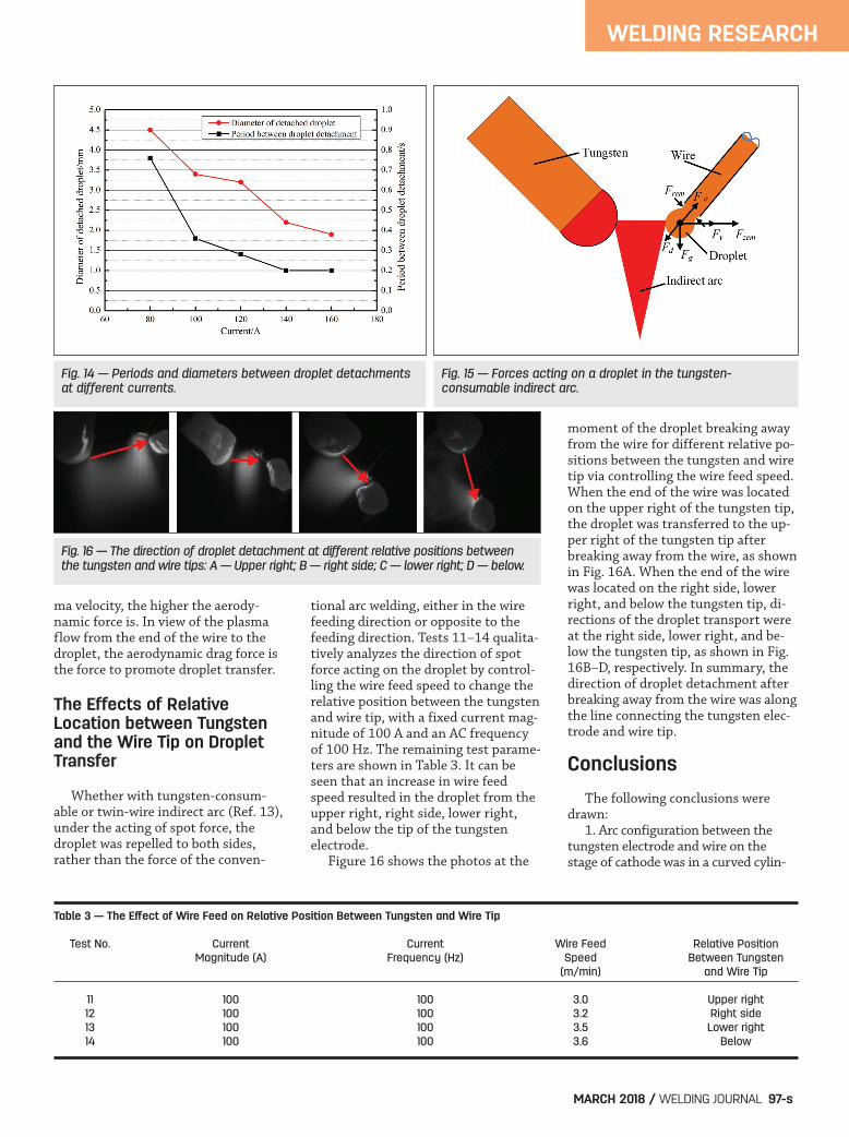
ferent currents. It can be seen that anincrease in current reduced the periodbetween the droplet detaching and di-ameter of the detached droplet. There are different types of detach-ing or retarding forces responsible forthe dynamic behavior of the droplet inthe tungsten-consumable indirect arc.Forces acting on the droplet includegravitational force Fg, surface tensionF, electromagnetic force Fem, spotforce Fv, and aerodynamic drag forceFd, as shown in Fig. 15. 1. Gravitational force, Fg
The force due to gravity can be ex-pressed as
where Vd and g are, respectively,
droplet volume and gravitational accel-eration. Gravitational force duringwelding always promotes detachmentof droplets. 2. Surface tension, F Surface tension is given by (Ref. 20)
where rw is the radius of the wire, isthe surface tension coefficient, and ew
is the unit vector in the wire direction.Surface tension is the force to keep thedroplet at the tip of the wire, impedingdetachment of the droplet. 3. The spot force, Fv
The indirect arc results in the polarspot at the cathode or anode spots onthe droplet. Pressure caused by the im-pact force of electron and ion flow, and
recoil force of metal vapor on the spot,is called the spot force. Since spots oc-cur on the left side of the droplet, theimpact force of electron and ion flows,and recoil force of metal vapor, pushedthe droplet toward the right side (seeFig. 13), and broke the droplet fromthe wire. In view of the deviation fromthe transition direction, spot force, Fv,impedes droplet transfer. 4. Electromagnetic force, Fem
Electromagnetic force or Lorentzforce can be calculated from
Consider uniform current density j ink direction on any cross section. Am-pere’s law (B/r)/r j gives az-imuthal magnetic field induction B jr/2. Equation 7 therefore gives
where magnetic force at the surfacevanishes because of zero current den-sity. Radius rmax is the maximum radiusof cylindrical arc. Equation 8 indicatesforce due to pinch effect. Electromag-netic force from Equation 7 can beprojected into any direction, for exam-ple, radial and horizontal directions,Frem and Fzem, by simply taking the in-ner product with unit vectors of radialand horizontal directions. Radial com-ponent of electromagnetic force, Frem,necks the droplet, promoting separa-tion of the droplet from the wire. Inview of pinch force, electromagneticforce from the small to large sectionresults in the component of magneticforce, Fzem, toward the right direction(see Fig. 15), leading to droplet break-ing away from the wire. 5. Aerodynamic drag force Fdrag
Aerodynamic drag force can be ex-pressed as (Ref. 20)
where the aerodynamic drag coeffi-cient, Cdrag, related to Reynolds num-ber, Re, is given by
The higher the droplet radius and plas-
Fem = jk�B�e�dVd = �er jB�drdAr��= �er
14μj2Ar (rmax
2 � r2 ) (8)
Fem = j�BdVd� (7)
F� =2�rw�ew (6)
Fg =�d gVd (5)
Fdrag =12�va
2�ard2Cdrag
va�va �
(9)
Cdrag =24Re
+ 61+Re
+0.4 (10)
Fig. 11 — Oscillation of a droplet within a cycle at 120 A.
Fig. 12 — Oscillation of a droplet within a cycle at 140 A.
Fig. 13 — Oscillation of a droplet within a cycle at 160 A.
Chen corrected (201757)_Layout 1 2/9/18 3:16 PM Page 96
ma velocity, the higher the aerody-namic force is. In view of the plasmaflow from the end of the wire to thedroplet, the aerodynamic drag force isthe force to promote droplet transfer.
The Effects of Relative Location between Tungstenand the Wire Tip on DropletTransfer
Whether with tungsten-consum-able or twin-wire indirect arc (Ref. 13),under the acting of spot force, thedroplet was repelled to both sides,rather than the force of the conven-
tional arc welding, either in the wirefeeding direction or opposite to thefeeding direction. Tests 11–14 qualita-tively analyzes the direction of spotforce acting on the droplet by control-ling the wire feed speed to change therelative position between the tungstenand wire tip, with a fixed current mag-nitude of 100 A and an AC frequencyof 100 Hz. The remaining test parame-ters are shown in Table 3. It can beseen that an increase in wire feedspeed resulted in the droplet from theupper right, right side, lower right,and below the tip of the tungsten electrode. Figure 16 shows the photos at the
moment of the droplet breaking awayfrom the wire for different relative po-sitions between the tungsten and wiretip via controlling the wire feed speed.When the end of the wire was locatedon the upper right of the tungsten tip,the droplet was transferred to the up-per right of the tungsten tip afterbreaking away from the wire, as shownin Fig. 16A. When the end of the wirewas located on the right side, lowerright, and below the tungsten tip, di-rections of the droplet transport wereat the right side, lower right, and be-low the tungsten tip, as shown in Fig.16B–D, respectively. In summary, thedirection of droplet detachment afterbreaking away from the wire was alongthe line connecting the tungsten elec-trode and wire tip.
Conclusions
The following conclusions weredrawn: 1. Arc configuration between thetungsten electrode and wire on thestage of cathode was in a curved cylin-
WELDING RESEARCH
MARCH 2018 / WELDING JOURNAL 97-s
Table 3 — The Effect of Wire Feed on Relative Position Between Tungsten and Wire Tip
Test No. Current Current Wire Feed Relative Position Magnitude (A) Frequency (Hz) Speed Between Tungsten (m/min) and Wire Tip
11 100 100 3.0 Upper right 12 100 100 3.2 Right side 13 100 100 3.5 Lower right 14 100 100 3.6 Below
Fig. 14 — Periods and diameters between droplet detachmentsat different currents.
Fig. 16 — The direction of droplet detachment at different relative positions betweenthe tungsten and wire tips: A — Upper right; B — right side; C — lower right; D — below.
Fig. 15 — Forces acting on a droplet in the tungsten-consumable indirect arc.
Chen corrected (201757)_Layout 1 2/9/18 3:16 PM Page 97
der shape. The cathode spot appearedand climbed along the droplet surface.The spot force responsible for deviationof the droplet toward the tungsten elec-trode decreased, resulting in the dropletto swing toward the tungsten side. 2. As polarity of the wire waschanged from cathode into anode, arcconfiguration was suddenly changedfrom the cylinder shape into a triangu-lar profile. A stable spot was main-tained on the upper part of thedroplet. The droplet began to swingtoward the wire side until polarity ofthe wire was changed from the anodeto cathode. 3. Motion of the cathode spot wasrelated to the spread of current intothe droplet. 4. The forces on the cathode spotwere greater than those on the anodespot. 5. The maximum climbing height ofcathode spot, maximum arc voltage,and voltage increase amplitude duringthe wire-negative half-wave decreasedas the AC frequency increased becauseincreased AC frequency means lesswire-negative duration in each AC cycle. 6. The transport direction of thedroplet after breaking away from thewire was along the line connecting thetips of tungsten electrode and wire.
This work is supported by the Bei-jing Natural Science Foundation(Grant No. 3162004) and NationalNatural Science Foundation of China(Grant No. 51505009 and 51475009).We also acknowledge the Program ofInvited Distinguished Professorshipsupported by IDHT20150210, No.456, 2014, Beijing Education Commit-tee, P. R. China.
1. Sykes, I., and Digiacomo, J. C. 1995.Automatic hot wire GTA welding of pipeoffers speed and increased deposition.Welding Journal 74(7): 53-s to 56-s. 2. Yang, C., Lin, S., and Liu, F. 2003. Re-search on the mechanism of penetrationincrease by flux in A-TIG welding. J. Mater.Process. Technol. 19: 225–227. 3. Cao, H. M., Wu, L., and Dong, H. G.2001. Current density distribution in double-sided GTAW process. J. Mater.Process. Technol. 17(1): 187, 188. 4. Leng, X. S., Zhang, G. J., and Cao, H.M. 2006. A study on twin-tungsten TIGwelding method. China Weld. 15(1): 49–52. 5. Kamiya, H., Fujita, T., and Enjo, Y.1985. Kikkuchi: Oxygen content and frac-ture toughness on MIG weld metal of SUS304 steel. Quart. J. Japan Weld. Soc. 3(3):138–145. 6. Kanemaru, S., Sasaki, T., and Sato, T.2013. Study for TIG–MIG hybrid weldingprocess. Weld. World 58(1): 11–18. 7. Kanemaru, S., Sasaki, T., and Sato, T.2015. Study for the mechanism of TIG-MIG hybrid welding process. Weld World.59(2): 261–268. 8. Chen, J. 2016. Influence of arcs in-teraction on TIG-MIG hybrid weldingprocess. Chin. J. Mech. Eng-En. 52(6):59–64. 9. Tao, Y., Zhang, S., and Gao, H. 2012.Analysis of mechanism for TIG-MIG hybridarc properties. Trans. China Weld. Inst.33(7): 25–28. 10. Zhang, Y. M., Jiang, M., and Lu, W.2004. Double electrodes improve GMAWheat input control. Welding Journal 83(11):39-s to 41s. 11. Chen, J. S., Lu, Y., Li, X. R., andZhang, Y. M. 2012. Gas tungsten arc weld-ing using an arcing wire. Welding Journal91(10): 261-s to 269-s. 12. Wang, J., Wang, Y. X., and Feng, J.C. 2009. A study on consumable aidedtungsten indirect arc welding. China Weld.18(3): 27–31. 13. Chen, S. J., Wang, L. W., and Wei, P.S. 2016. Sustaining the inter-wire arc in
twin-wire indirect arc welding. J. Manuf.Process. 21: 69–74. 14. Chen, S. J., Zhang, L., and Bai, L. L.The welding method of twin-wire indirectarc. China patent application no.CN201310456520.9, 2013. 15. Tashiro, S., Yuji, T., Fujimaru, A.,Kinoshita, H., Yasui, K., Bouno, T.,Methong, T., and Tanaka, M. 2015. Opticalobservation of cathode spot in AC tung-sten intert gas (TIG) welding on aluminumplate using helium. Trans. JWRI 44: 1–4. 16. Garner, A. L. 2008. Cathode spotmotion in an oblique magnetic field. Appl.Phys. Lett. 92: 011505. 17. Waszink, J. H., and Piena, M. J.1986. Experimental investigation of dropdetachment and drop velocity in GMAW.Welding Journal 65(11): 289-s to 298-s. 18. Sherman, J. C., Webster, R., Jenk-ins, J. E., and Holmes, R. 1975. Cathodespot motion in high-current vacuum arcson copper electrodes. J. Phys. D: Appl. Phys.8: 696–702. 19. Perskii, N. E., Sysun, V. I., and Khromoi, D. Y. 1989. Dynamics of vacuum-discharge cathode spots. High Temp. 27:832–839. 20. Lancaster, J. F. The Physics of Weld-ing. Oxford, England: Pergamon Press.
WELDING RESEARCH
WELDING JOURNAL / MARCH 2018, VOL. 9798-s
SHUJUN CHEN, LIWEI WANG, JUN XIAO([email protected]), and PENGSHENGWEI are with the Engineering ResearchCenter of Advanced ManufacturingTechnology for Automotive Compo-nents, Ministry of Education, BeijingUniversity of Technology, Beijing,China. WANG is also with the School ofMaterials Science and Engineering,Hebei University of Science and Tech-nology, Shijiazhuang, China. In addi-tion, WEI is with the Department ofMechanical and Electro-MechanicalEngineering, National Sun Yat-Sen Uni-versity, Kaohsiung, Taiwan.
Acknowledgments
References
Chen corrected (201757)_Layout 1 2/9/18 3:16 PM Page 98