ar-b1653 3.5” ebc with via mark processor, vga/ lcd/ lan ... · ar-b1653 user’s guide 1...
TRANSCRIPT

AR-B1653 User’s Guide
1
AR-B1653 3.5” EBC with VIA Mark Processor,
VGA/ LCD/ LAN/ USB CPU Board
User’ s Guide
Edition: 1.0 Book Number: AR-B1653-07.0701

AR-B1653 User’s Guide
2
Table of Contents 0.PREFACE……………................................................................................................................................................... 3
0.1 COPYRIGHT NOTICE AND DISCLAIMER.....................................................................................................................................3 0.2 WELCOME TO THE AR-B1653 CPU BOARD................................................................................................................................3 0.3 BEFORE YOU USE THIS GUIDE...................................................................................................................................................3 0.4 RETURNING YOUR BOARD FOR SERVICE.................................................................................................................................3 0.5 TECHNICAL SUPPORT AND USER COMMENTS ........................................................................................................................4 0.6 STATIC ELECTRICITY PRECAUTIONS.. ......................................................................................................................................4
1. INTRODUCTION.......................................................................................................................................................... 5 1.1SPECIFICATIONS............................................................................................................................................................................6 1.2 PACKING LIST................................................................................................................................................................................6
2. SETTING UP SYSTEM................................................................................................................................................ 7 2.1 AR-B1653 OVERVIEW....................................................................................................................................................................7 2.2 SYSTEM SETTINGS.......................................................................................................................................................................8
2.2.1 Keyboard & Mouse Connector (KM2).......................................................................................................................................8 2.2.2 SDRAM SOCKET 144 PIN (DIMM1)........................................................................................................................................8 2.2.3 Hard Disk (IDE) Connector (IDE1) ...........................................................................................................................................9 2.2.4 Parallel Port Connector (LPT1) ................................................................................................................................................9 2.2.5 CRT Connector (VGA1)..........................................................................................................................................................10 2.2.6 USB Connector (USB1)..........................................................................................................................................................10 2.2.7 LCD VOLTAGE SELECT (J1) ................................................................................................................................................11 2.2.8 EXTERNAL BUZZER (BZ1) ...................................................................................................................................................11 2.2.9 Serial Port (COM1, COM2).....................................................................................................................................................11 2.2.10 Clear CMOS (JBAT1) ...........................................................................................................................................................11 2.2.11 GPIO Port (CN1) ..................................................................................................................................................................12 2.2.12 Touch Screen Connector (TSC1) .........................................................................................................................................12 2.2.13 26-Pin Audio Connector (AUDIO1).......................................................................................................................................12 2.2.14 LCD Inverter Connector (CN2) .............................................................................................................................................13 2.2.15 LED (LED1) ..........................................................................................................................................................................13 2.2.16 Ethernet RJ-45 Connector (LAN1) .......................................................................................................................................13 2.2.17 Reset Button (RST1) ............................................................................................................................................................13 2.2.18 Power Connector (PWR1) ....................................................................................................................................................14 2.2.19 PC/104 Connector (PC104)..................................................................................................................................................14 2.2.20 Compact Flash Connector (CF1)..........................................................................................................................................14 2.2.21 CF Master/Salver Connector (J4).........................................................................................................................................14 2.2.22 18-bit LCD Panel Connector (LCD1) ....................................................................................................................................15 2.2.23 Battery Connector (BT1).......................................................................................................................................................15
3. WATCHDOG TIMER ................................................................................................................................................. 15 3.1 WATCHDOG TIMER SETTING ....................................................................................................................................................16 3.2 WATCHDOG TIMER TRIGGER....................................................................................................................................................16
4. BIOS CONSOLE........................................................................................................................................................ 16 4.1 BIOS SETUP OVERVIEW.............................................................................................................................................................17 4.2 ADVANCED...................................................................................................................................................................................18 4.3 PERIPHERAL................................................................................................................................................................................19 4.4 PNP/PCI……………………………………………………………………………………………………………………………………….21 4.5 H/W MONITOR..............................................................................................................................................................................22 4.6 BOOT…………………………………………………………………………………………………………………………………………..23 4.7 BIOS EXIT. ....................................................................................................................................................................................24
APPENDIX A. MEMORY MAP ...................................................................................................................................... 24 APPENDIX B. INTERRUPT REQUEST (IRQ)............................................................................................................... 25

AR-B1653 User’s Guide
3
0. PREFACE
0.1 COPYRIGHT NOTICE AND DISCLAIMER This document is copyrighted, 2007, by Acrosser Technology Co., Ltd. All rights are reserved. No part of this manual may be reproduced, copied, transcribed, stored in a retrieval system, or translated into any language or computer language in any form or by any means, such as electronic, mechanical, magnetic, optical, chemical, manual or other means without the prior written permission or original manufacturer. Acrosser Technology assumes no responsibility or warranty with respect to the content in this manual and specifically disclaims any implied warranty of merchantability or fitness for any particular purpose. Furthermore, Acrosser Technology reserves the right to make improvements to the products described in this manual at any times without notice. Such revisions will be posted on the Internet (WWW.ACROSSER.COM) as soon as possible. Possession, use, or copy of the software described in this publication is authorized only pursuant to valid written license from Acrosser or an authorized sub licensor. ACKNOWLEDGEMENTS Acrosser, AWARD, IBM PC/AT, VIA, Windows 3.1, MS-DOS…are registered trademarks. All other trademarks and registered trademarks are the property of their respective owners.
0.2 WELCOME TO THE AR-B1653 CPU BOARD This guide introduces the Acrosser AR-B1653 CPU Board. Use information provided in this manual describes this card’s functions and features. It also helps you start, set up and operate your AR-B1653. General system information can also be found in this publication.
0.3 BEFORE YOU USE THIS GUIDE Please refer to the Chapter 2, “System Setting,” in this guide, if you have not already installed this AR-B1653. Check the packing list before you install and make sure the accessories are completely included. AR-B1653 CD provides the newest information regarding the CPU card. Please refer to the files of the enclosed utility CD. It contains the modification and hardware & software information, and adding the description or modification of product function after manual printed.
0.4 RETURNING YOUR BOARD FOR SERVICE If your board requires any services, contact the distributor or sales representative from whom you purchased the product for service information. If you need to ship your board to us for service, be sure it is packed in a protective carton. We recommend that you keep the original shipping container for this purpose. You can help assure efficient servicing for your product by following these guidelines: 1. Include your name, address, daytime telephone, facsimile number and E-mail. 2. A description of the system configuration and/or software at the time of malfunction. 3. A brief description of the problem occurred.
AR-B1653 User’s Guide
4
0.5 TECHNICAL SUPPORT AND USER COMMENTS Users comments are always welcome as they assist us in improving the quality of our products and the readability of our publications. They create a very important part of the input used for product enhancement and revision. We may use and distribute any of the information you provide in any way appropriate without incurring any obligation. You may, of course, continue to use the information you provide. If you have any suggestions for improving particular sections or if you find any errors on it, please send your comments to Acrosser Technology Co., Ltd. or your local sales representative and indicate the manual title and book number. Internet electronic mail to: [email protected] [email protected]
0.6 STATIC ELECTRICITY PRECAUTIONS Before removing the board from its anti-static bag, read this section about static electricity precautions. Static electricity is a constant danger to computer systems. The charge that can build up in your body may be more than sufficient to damage integrated circuits on any PC board. It is, therefore, important to observe basic precautions whenever you use or handle computer components. Although areas with humid climates are much less prone to static build-up, it is always best to safeguard against accidents that may result in expensive repairs. The following measures should be sufficient to protect your equipment from static discharge: Touch a grounded metal object to discharge the static electricity in your body (or ideally, wear a grounded
wrist strap). When unpacking and handling the board or other system components, place all materials on an anti-static
surface. Be careful not to touch the components on the board, especially the “golden finger” connectors on the
bottom of the board.
AR-B1653 User’s Guide
5
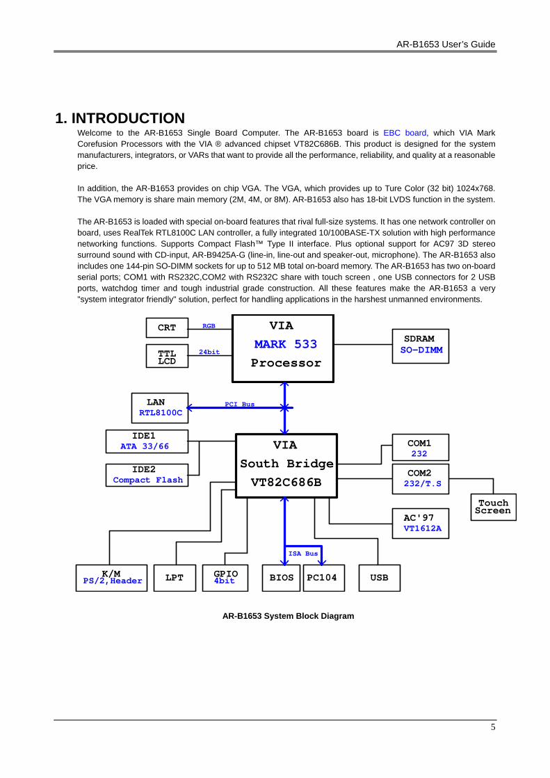
1. INTRODUCTION Welcome to the AR-B1653 Single Board Computer. The AR-B1653 board is EBC board, which VIA Mark Corefusion Processors with the VIA ® advanced chipset VT82C686B. This product is designed for the system manufacturers, integrators, or VARs that want to provide all the performance, reliability, and quality at a reasonable price. In addition, the AR-B1653 provides on chip VGA. The VGA, which provides up to Ture Color (32 bit) 1024x768. The VGA memory is share main memory (2M, 4M, or 8M). AR-B1653 also has 18-bit LVDS function in the system. The AR-B1653 is loaded with special on-board features that rival full-size systems. It has one network controller on board, uses RealTek RTL8100C LAN controller, a fully integrated 10/100BASE-TX solution with high performance networking functions. Supports Compact Flash™ Type II interface. Plus optional support for AC97 3D stereo surround sound with CD-input, AR-B9425A-G (line-in, line-out and speaker-out, microphone). The AR-B1653 also includes one 144-pin SO-DIMM sockets for up to 512 MB total on-board memory. The AR-B1653 has two on-board serial ports; COM1 with RS232C,COM2 with RS232C share with touch screen , one USB connectors for 2 USB ports, watchdog timer and tough industrial grade construction. All these features make the AR-B1653 a very "system integrator friendly" solution, perfect for handling applications in the harshest unmanned environments.
VIA
VT82C686BSouth Bridge
VIA
CRT
SO-DIMMSDRAM
ProcessorMARK 533
IDE1
RTL8100CLAN
LCDTTL
Compact FlashIDE2
ATA 33/66
LPT 4bitGPIO PC104BIOSPS/2,Header
K/M
AC'97ScreenTouch
USB
VT1612A
232/T.SCOM2
232COM1
ISA Bus
PCI Bus
RGB
24bit
AR-B1653 System Block Diagram

AR-B1653 User’s Guide
6
1.1 SPECIFICATIONS CPU: On-board VIA Mark Corefusion Processor 533MHz Chipset: VIA ® VT82C686B RAM memory: Supports SDRAM PC133, on-board 144-pin SO-DIMM up to 512MB SDRAM memory
module VGA Controller: Embedded VGA controller, Screen Resolution: up to Ture Color(32 bit)1024x768. Display Interface: CRT – D-SUB 15-pin female connector
LCD –for 18 bit TFT LCD Panel, 2x13x2.0mm pin-header connector Ultra ATA/33/66/100 IDE Interface: One PCI Enhance IDE channel. The south bridge VT82C686B supports
Ultra ATA/33 IDE interface. To support Ultra ATA66/100 Hard disk, a specified cable must be available. C. F.: Supports Compact Flash Type II interface Series ports: On-board one D-SUB 9-pin male connector for COM1 with RS-232C.On-board one
2x5x2.0mm pin-header connector for COM2 with RS-232C share with Touch Screen Touch Screen uses 2.0mm 5-pin header connector Parallel Port: On-board one 2x13x2.0mm pin-header connector for Parallel port, supports SPP/EPP/ECP
modes USB port: On-board one 2x4x2.0mm pin-header connector for 2 USB ports Audio: onboard AC’97 Codec, On-board one 2x13x2.0mm pin-header for Audio interface Supports two
channel Left/Right Line IN/OUT, and Left/Right speaker out, MIC IN. Watchdog timer: Software programmable 1~63sec. Ethernet: On-board one Realtek RT8100C, supports 10/100Mbps Base-T with RJ-45 connector. K/B & Mouse: On-board PS/2 Keyboard and Mouse connector Power Req.: +5V 2.5A and +12V 1A maximum PC Board: 8 layers, EMI considered Dimensions: 145mm x 102mm (5.7” x 4”) Operating Temperature: 0° ~ 60℃
1.2 PACKING LIST These accessories are included with the system. Before you begin installing your AR-B1653 board, please make sure that the following items have been included inside the AR-B1653 package. The quick setup manual 1 AR-B1653 CPU board 1 AR-B9425A-G SB Transfer (option) 1 AR-B9425A-G Audio Cable (option) 2 USB port on one bracket cable (option) 1 Had disk adapter (44Pin) (option) 1 PS/2 Mouse & Keyboard interface Y-Cable

AR-B1653 User’s Guide
7
2. SETTING UP SYSTEM This chapter describes how to install the AR-B1653. At first, the layout of AR-B1653 is shown, and the unpacking information that you should be careful is described. Overview System Settings
2.1 AR-B1653 OVERVIEW
TOP PLACEMENT
BOTTOM PLACEMENT

AR-B1653 User’s Guide
8
2.2 SYSTEM SETTINGS Jumper pins allow you to set specific system parameters. Set them by changing the pin location of the jumper blocks. (A jumper block is a small plastic-encased conductor that slips over the pins.) To change a jumper setting, remove the jumper from its current location with your fingers or small needle-nosed pliers. Place the jumper over the two pins designated for the desired setting. Press the jumper evenly onto the pins. Be careful not to bend the pins. We will show the locations of the AR-B1653 jumper pins, and the factory-default settings. CAUTION: Do not touch any electronic components unless you are safely grounded. Wear a grounded wrist strap or touch an exposed metal part of the system unit chassis. The static discharges from your fingers can permanently damage electronic components.
2.2.1 Keyboard & Mouse Connector (KM2) The KM2 is a 6-pin Mini DIN keyboard & Mouse connector. This keyboard & Mouse connector is PS/2 type connector. This connector is also for a standard IBM-compatible keyboard when used with the included PS/2 keyboard & Mouse adapter cable.
2.2.2 SDRAM SOCKET 144 PIN (DIMM1) It can assemble 16/32/64/128/256/512MB 144 pin DIMM Module Memory. When you set up 144-pin DIMM Module Memory, AR-B1653 will auto-detect DRAM, and adopt correct save in order to make memory work till the best situation. Caution: Set up 144-pin DIMM Module Memory, please insert into slot vertical, if the direction is wrong and it leads to failure, please confirm the direction is right. DRAM Configuration (DIMM1) 11144
144 pin SO-DIMM

AR-B1653 User’s Guide
9
2.2.3 Hard Disk (IDE) Connector (IDE1) 44 Pin Hard Disk Connector (IDE1) The on-board 44-pin mini-pitched IDE interface is used to let user support either a 3.5" HDD with 44 to 40pin adapter cable.
1 43
2 44
Pin Signal Pin Signal 1 -RESET 2 GROUND 3 DATA 7 4 DATA 8 5 DATA 6 6 DATA 9 7 DATA 5 8 DATA 10 9 DATA 4 10 DATA 11 11 DATA 3 12 DATA 12 13 DATA 2 14 DATA 13 15 DATA 1 16 DATA 14 17 DATA 0 18 DATA 15 19 GROUND 20 Not Used 21 IDEDREQ 22 GROUND 23 -IOW A 24 GROUND 25 -IOR A 26 GROUND 27 IDEIORDYA 28 GROUND 29 -DACKA 30 GROUND 31 AINT 32 Not Used 33 SA 1 34 Data33_66 35 SA 0 36 SA 2 37 CS 0 38 CS 1 39 HD LED A 40 GROUND 41 VCC 42 VCC 43 GROUND 44 Not Used
2.2.4 Parallel Port Connector (LPT1) The connector for the parallel port is a 26-pin header connector.
1 25
2 26
Parallel Port Connector
DB-25 Signal DB-25 Signal 1 -Strobe 14 -Auto Form Feed2 Data 0 15 -Error 3 Data 1 16 -Initialize 4 Data 2 17 -Printer Select In5 Data 3 18 Ground 6 Data 4 19 Ground 7 Data 5 20 Ground 8 Data 6 21 Ground 9 Data 7 22 Ground
10 -Acknowledge 23 Ground 11 Busy 24 Ground 12 Paper 25 Ground 13 Printer Select 26 No Used

AR-B1653 User’s Guide
10
2.2.5 CRT Connector (VGA1) VGA1 is a standard 15-pin D-SUB connector commonly used for VGA.
2.2.6 USB Connector (USB1) The Universal Serial Bus (USB) controller is USB V1.1 and Universal HCI V1.1 compliant. The Universal Serial Bus (USB) standard is a low-to-medium speed interface for the connection of PC peripherals, which gives complete Plug & Play, and hot attach/detach for up to 127 external devices. USB is a leading edge technology that allows the user to quickly and easily add a wide range of peripheral devices from printers to keyboards and telephony devices to fax/modems. Universal Host Controller Interface (UHCI) and future support for the Open Host Controller Interface (OHCI) ensure USB compatibility and usability well into the future. The CPU board supports four Universal Serial Bus ports. An optional external port bracket attaches to the onboard connector via an attached cable. With the optional port bracket installed you can attach USB devices to the external ports. If the USB ports are installed, the USB Controller line in the Integrated Peripherals section of the CMOS Setup utility must be set to “Enabled”. USB ports may also require Operating System support for USB devices.
USB1 use an adapter cable to interface with external equipment.
2.2.7 LCD VOLTAGE SELECT (J1)

AR-B1653 User’s Guide
11
2.2.8 EXTERNAL BUZZER (BZ1)
2.2.9 Serial Port (COM1, COM2) AR-B1653 is equipped with four serial ports. COM1 is a standard RS-232 interface. COM2/ use an adapter cable to interface with external equipment.
A. COM1
USED RS232
COM1
9 8 7
6
5 4
3 2 1
B. COM2
USED RS232
2.2.10 Clear CMOS (JBAT1)
AR-B1653 User’s Guide
12
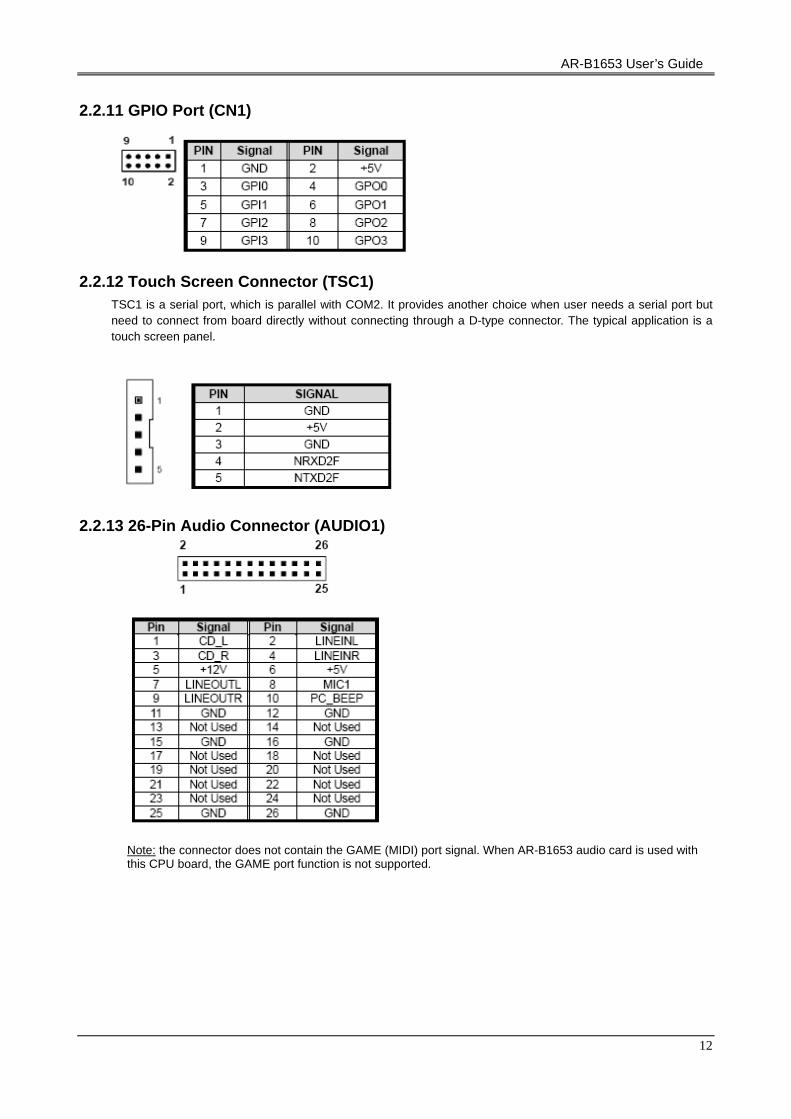
2.2.11 GPIO Port (CN1)
2.2.12 Touch Screen Connector (TSC1)
TSC1 is a serial port, which is parallel with COM2. It provides another choice when user needs a serial port but need to connect from board directly without connecting through a D-type connector. The typical application is a touch screen panel.
2.2.13 26-Pin Audio Connector (AUDIO1)
Note: the connector does not contain the GAME (MIDI) port signal. When AR-B1653 audio card is used with this CPU board, the GAME port function is not supported.
AR-B1653 User’s Guide
13
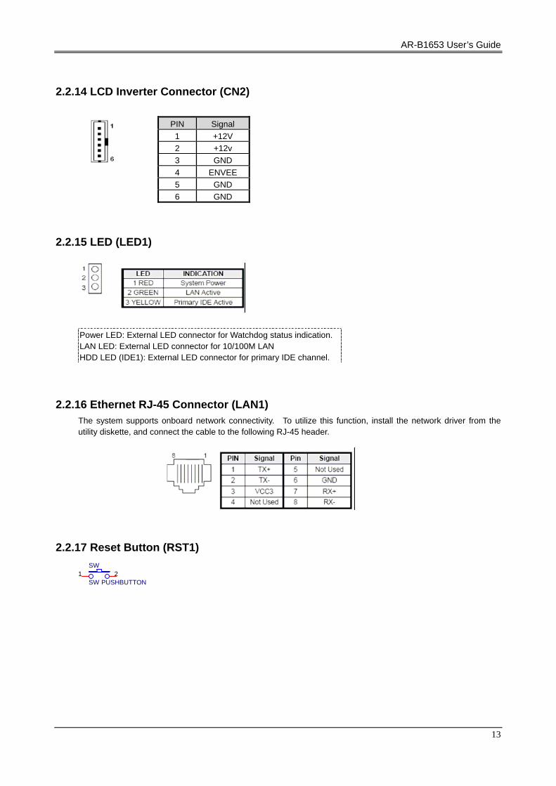
2.2.14 LCD Inverter Connector (CN2)
2.2.15 LED (LED1)
2.2.16 Ethernet RJ-45 Connector (LAN1) The system supports onboard network connectivity. To utilize this function, install the network driver from the utility diskette, and connect the cable to the following RJ-45 header.
2.2.17 Reset Button (RST1) SW
SW PUSHBUTTON 1 2
PIN Signal 1 +12V 2 +12v 3 GND 4 ENVEE 5 GND 6 GND
Power LED: External LED connector for Watchdog status indication. LAN LED: External LED connector for 10/100M LAN HDD LED (IDE1): External LED connector for primary IDE channel.

AR-B1653 User’s Guide
14
2.2.18 Power Connector (PWR1) The PWR1 is a 4-pin power connector. It’s the standard connector on all Acrosser boards.
2.2.19 PC/104 Connector (PC104) (1) 64 Pin PC/104 Connector A&B
1
2 64
63 (2) 40 Pin PC/104 Connector C&D
1
2 40
39 Note: If the content in setting is inconsistent with the CD-ROM, please refer to the setting as the priority.
2.2.20 Compact Flash Connector (CF1)
2.2.21 CF Master/Salver Connector (J4)

AR-B1653 User’s Guide
15
2.2.22 18-bit LCD Panel Connector (JCD1)
2.2.23 Battery Connector (BT1)
3. WATCHDOG TIMER This section describes the use of Watchdog Timer, including disable, enable, and trigger. AR-B1653 is equipped with a programmable time-out period watchdog timer that occupies I/O port 443H. Users can use simple program to enable the watchdog timer. Once you enable the watchdog timer, the program should trigger it every time before it times out. Watchdog Timer will generate a response (system or IRQ) due to system fails to trigger or disable watchdog timer before preset timer, times out.
WatchdogRegister
Time Base
Counter andCompartor
RESET
Enable(D7)Time Factor
(D0-D5)
Write andTrigger
Watchdog Block Diagram

AR-B1653 User’s Guide
16
3.1 WATCHDOG TIMER SETTING The watchdog timer is a circuit that maybe be used from your program software to detect crash or hang up.
The Watchdog timer is automatically disabled after reset. Once you enabled the watchdog timer, your program should trigger the watchdog timer every time before it times out. After you trigger the watchdog timer, the timer will be set to zero and start to count again. If your program fails to trigger the watchdog timer before times out, it will generate a reset pulse to reset the system or trigger the IRQ 9 signal in order to tell your system that the watchdog time is out. Please refer to the following table in order to properly program Watchdog function
D7 D6 D5 D4 D3 D2 D1 D0
1 Enable Reset
0 Disable IRQ 9
Time period
Users could test watchdog function under ‘Debug’ program as follows:
C:>debug
O 443 C8H Generally, watchdog function would reset system after 8 seconds
O 443 0H Disable watchdog function
C:>debug O 443 88H
Generally, watchdog function would generate IRQ 9 after 8 seconds O 443 0H
Disable watchdog function
3.2 WATCHDOG TIMER TRIGGER After you enable the watchdog timer, your program must write the same factor as triggering to the watchdog timer
at least once during every time-out period. You can change the time-out period by writing another timer factor to the watchdog register at any time, and you must trigger the watchdog during every new time-out period in next trigger.
4. BIOS CONSOLE This chapter describes the AR-B1653 BIOS menu displays and explains how to perform common tasks needed to get up and running, and presents detailed explanations of the elements found in each of the BIOS menus. The following topics are covered:
BIOS Setup Overview Advanced CMOS Setup Peripheral Setup Boot BIOS Exit
AR-B1653 User’s Guide
17
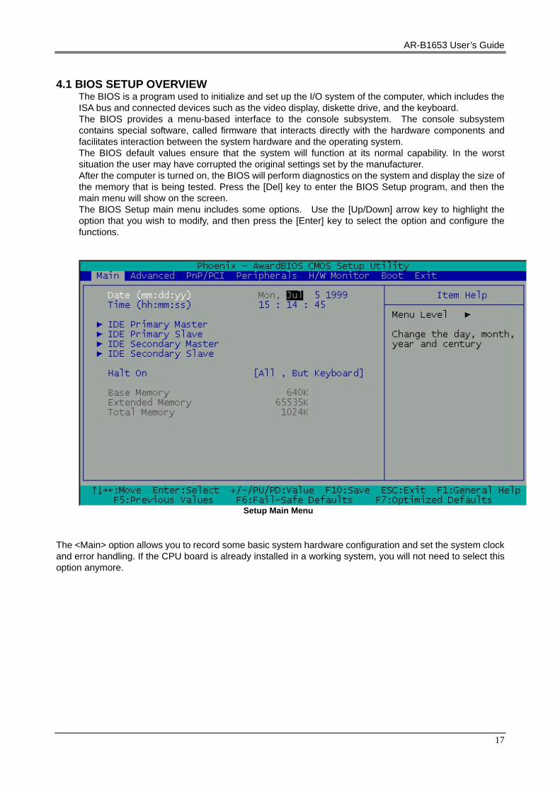
4.1 BIOS SETUP OVERVIEW
The BIOS is a program used to initialize and set up the I/O system of the computer, which includes the ISA bus and connected devices such as the video display, diskette drive, and the keyboard. The BIOS provides a menu-based interface to the console subsystem. The console subsystem contains special software, called firmware that interacts directly with the hardware components and facilitates interaction between the system hardware and the operating system. The BIOS default values ensure that the system will function at its normal capability. In the worst situation the user may have corrupted the original settings set by the manufacturer. After the computer is turned on, the BIOS will perform diagnostics on the system and display the size of the memory that is being tested. Press the [Del] key to enter the BIOS Setup program, and then the main menu will show on the screen. The BIOS Setup main menu includes some options. Use the [Up/Down] arrow key to highlight the option that you wish to modify, and then press the [Enter] key to select the option and configure the functions.
Setup Main Menu
The <Main> option allows you to record some basic system hardware configuration and set the system clock and error handling. If the CPU board is already installed in a working system, you will not need to select this option anymore.
AR-B1653 User’s Guide
18
Date & Time Setup Highlight the <Date> field and then press the [Page Up] /[Page Down] or [+]/[-] keys to set the current date. Follow the month, day and year format. Highlight the <Time> field and then press the [Page Up] /[Page Down] or [+]/[-] keys to set the current date. Follow the hour, minute and second format. The user can bypass the date and time prompts by creating an AUTOEXEC.BAT file. For information on how to create this file, please refer to the MS-DOS manual.
Hard Disk Setup
The BIOS supports various types for user settings, The BIOS supports <Pri Master>, <Pri Slave>, <Sec Master> and <Sec Slave> so the user can install up to two hard disks. For the master and slave jumpers, please refer to the hard disk’s installation descriptions and the hard disk jumper settings in section three of this manual.
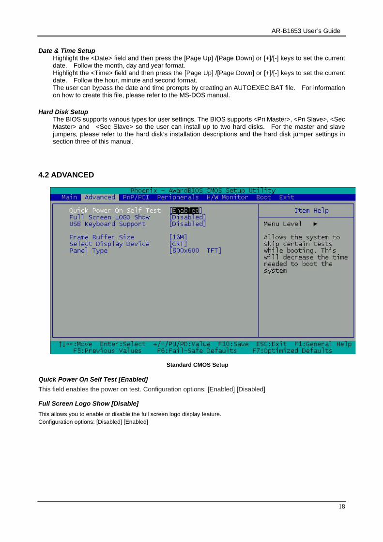
4.2 ADVANCED
Standard CMOS Setup
Quick Power On Self Test [Enabled] This field enables the power on test. Configuration options: [Enabled] [Disabled]
Full Screen Logo Show [Disable] This allows you to enable or disable the full screen logo display feature. Configuration options: [Disabled] [Enabled]

AR-B1653 User’s Guide
19
USB Keyboard Support [Disable] SUPPORT USB KEYBORD
Frame Buffer Size [16M]
4.3 PERIPHERALS
Peripherals
Onboard Serial Port 1 [AUTO]
Onboard Serial Port 2 [Auto] Choose serial port 1 to 2 I/O address. Do not set port 1 to 2 to the same address except for Disabled or Auto.
AR-B1653 User’s Guide
20
UART 2 MODE [Standard]
Select an operating mode for the second serial port:
Normal RS-232C serial port
Standard RS-232C serial port
IrDA 1.0 Infrared port compliant with IrDA 1.0 specification
IrDA SIR IrDA-compliant serial infrared port
IrDA MIR 1 MB/sec infrared port
IrDA FIR Fast Infrared standard
FIR Fast Infrared standard
MIR 0.57M 0.57-MB/sec infrared port
MIR 1.15M 1.15-MB/sec infrared port
Sharp IR 4-Mb/s data transmission
HPSIR IrDA-compliant serial infrared port
ASK IR Amplitude shift keyed infrared port
Onboard Parallel Port [378H/IRQ7] This field allows you to set the address of the onboard parallel port connector. If you disable this field, the Parallel Port Mode and ECP DMA Select configurations are not available. Configuration options: [Disabled] [378H/IRQ7] [278H/IRQ5]
Onboard Parallel Mode [Normal] This field allows you to set the operation mode of the parallel port. [Normal] allows normal-speed operation but in one direction only; [EPP] allows bidirectional parallel port operation; [ECP] allows the parallel port to operate in bidirectional DMA mode; [ECP+EPP] allows normal speed operation in a two-way mode. Configuration options: [Normal] [EPP] [ECP] [ECP+EPP]
ECP Mode use DMA [3] This field allows you to configure the parallel port DMA channel for the selected ECP mode. This selection is available only if you select [ECP] or [ECP+EPP] in Parallel Port Mode above. Configuration options: [1] [3]
Parallel port EPP Type [EPP1.9] The mode depends on your external device that connects to this port.
Onboard FDD controller [Enables] Use the on-board floppy controller
OnChip USB controller [Enables] This should be enabled if your system has a USB installed on the system board and you want to use it. Even when so equipped, if you add a higher performance controller, you will need to disable this feature.

AR-B1653 User’s Guide
21
4.4 PNP/PCI
PnP/PCI
Reset Configuration Data [Disable] Normally, you leave this field Disabled. Select Enabled to reset Extended System Configuration Data (ESCD) when you exit Setup if you have installed a new add-on and the system reconfiguration has caused such a serious conflict that the operating system cannot boot.
Resources Controlled By [Auto (ESCD)] This field sets control over the IRQ resources by the automatic (ESCD) system or manual assignment of IRQ channels. The default enables automatic (ESCD) control. Configuration options: [Auto(ESCD)] [Manual].
AR-B1653 User’s Guide
22
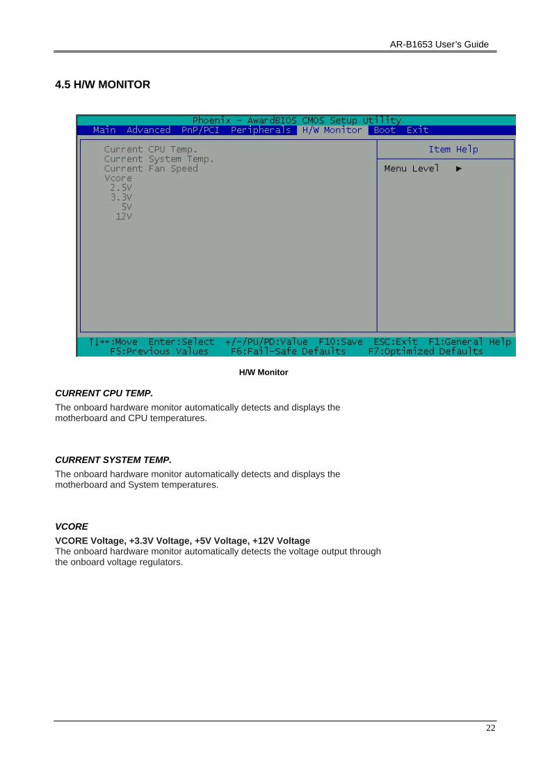
4.5 H/W MONITOR
H/W Monitor
CURRENT CPU TEMP. The onboard hardware monitor automatically detects and displays the motherboard and CPU temperatures.
CURRENT SYSTEM TEMP. The onboard hardware monitor automatically detects and displays the motherboard and System temperatures.
VCORE VCORE Voltage, +3.3V Voltage, +5V Voltage, +12V Voltage The onboard hardware monitor automatically detects the voltage output through the onboard voltage regulators.
AR-B1653 User’s Guide
23
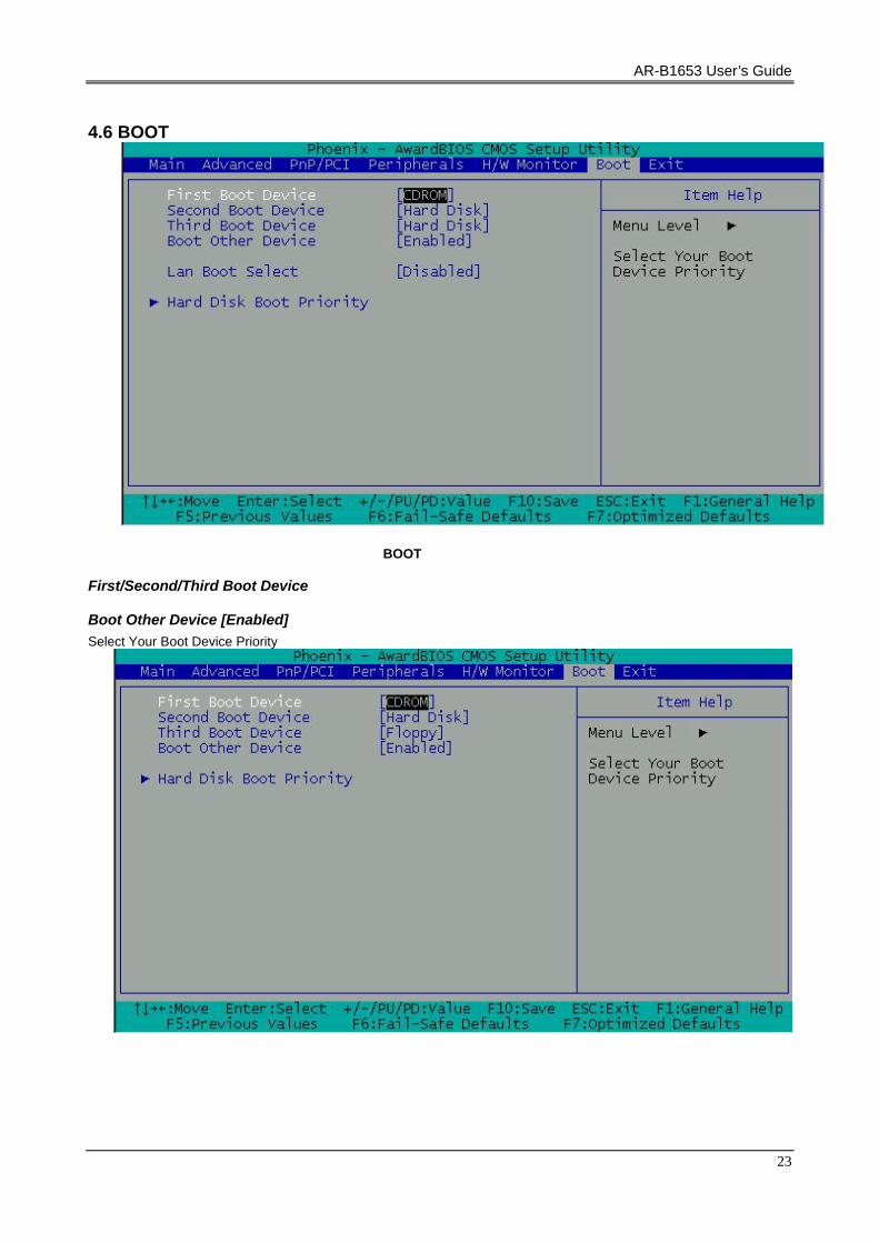
4.6 BOOT
BOOT
First/Second/Third Boot Device
Boot Other Device [Enabled] Select Your Boot Device Priority

AR-B1653 User’s Guide
24
4.7 BIOS EXIT
Exit When you have made all of your selections from the various menus in the Setup program, save your changes and exit Setup. Select Exit from the menu bar to display the following menu. Save & Exit Setup Type “Y” will quit the Setup Utility and save the user setup value to RTC CMOS. Type “N” will return to Setup Utility.
. Load Optimized Defaults Selecting this field loads the factory defaults for BIOS and Chipset Features, which the System automatically detects.
Exit Without Saving Type “Y” will quit the Setup Utility without saving to RTC CMOS. Type “N” will return to Setup Utility.
APPENDIX A. MEMORY MAP
Memory Map:
MEMORY MAP ASSIGNMENT
00000000-0009FFFF System board
0009F000-000BFFFF PCI bus
000A0000-000BFFFF S3 Graphics Twister+S3Hotkey

AR-B1653 User’s Guide
25
000A0000-000BFFFF VIA CPU to AGP Controller
000CE000-000CFFFF Motherboard resources
000CE000-000EFFFF PCI bus
000F0000-000F3FFF Motherboard resources
000F4000-000F7FFF Motherboard resources
000F8000-000FFFFF Motherboard resources
00100000-00FFFFFF System board
07000000-FEBFFFFF PCI bus
E0000000-E7FFFFFF S3 Graphics Twister+S3Hotkey
E0000000-E7FFFFFF VIA CPU to AGP Controller
E8000000-EBFFFFFF VIA CPU to AGP Controller
EC000000-EC07FFFF S3 Graphics Twister+S3Hotkey
EC000000-EC0FFFFF VIA CPU to AGP Controller
EC110000-EC1100FF Realtek RTL8139 Family PCI Fast Ethernet NIC
FEC00000-FEC0FFFF System board
FEC01000-FEDFFFFF PCI bus
FEE00000-FEE0FFFF System board
FEE01000-FFFEFFFF PCI bus
FFFE0000-FFFFFFFF System board
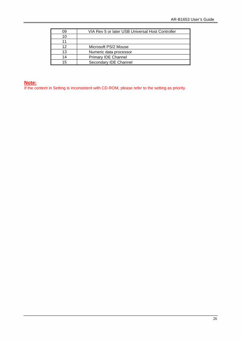
APPENDIX B. INTERRUPT REQUEST (IRQ)
SETTING HARDWARE USING THE SETTING
00 System timer 01 PC/AT Enhanced PS/2 Keyboard (101/102-Key) 02 03 Communications Port (COM2) 04 Communications Port (COM1) 05 Realtek RTL8139 Family PCI Fast Ethernet NIC 05 Vinyl AC’97 Codec Combo Driver (WDM) 06 Standard floppy disk controller 07 08 System CMOS/real time clock 09 VIA Rev 5 or later USB Universal Host Controller
AR-B1653 User’s Guide
26
09 VIA Rev 5 or later USB Universal Host Controller 10 11 12 Microsoft PS/2 Mouse 13 Numeric data processor 14 Primary IDE Channel 15 Secondary IDE Channel
Note: If the content in Setting is inconsistent with CD-ROM, please refer to the setting as priority.