aquatrak™ cvl - product manual - tritech...aquatrak™ cvl 0713-som-00002, issue: 2 1 © tritech...
TRANSCRIPT

AquaTrak™ CVL
0713-SOM-00002, Issue: 2 1 © Tritech International Ltd.
AquaTrak™ CVL
Product Manual
0713-SOM-00002, Issue: 2

AquaTrak™ CVL
0713-SOM-00002, Issue: 2 2 © Tritech International Ltd.
© Tritech International Ltd
The copyright in this document is the property of Tritech International Ltd. The document is supplied by Tritech International Ltd onthe understanding that it may not be copied, used, or disclosed to others except as authorised in writing by Tritech International Ltd.
Tritech International Ltd reserves the right to change, modify and update designs and specifications as part of their ongoingproduct development programme.
All product names are trademarks of their respective companies.

AquaTrak™ CVL
0713-SOM-00002, Issue: 2 3 © Tritech International Ltd.
Table of ContentsHelp & Support ........................................................................................................... 4Warning Symbols ........................................................................................................ 5Special Considerations ................................................................................................ 61. Introduction ............................................................................................................. 7
1.1. Overview ..................................................................................................... 71.2. Features ...................................................................................................... 7
2. Specification ........................................................................................................... 92.1. Dimensions .................................................................................................. 92.2. Acoustic Properties ...................................................................................... 92.3. Physical and Electrical Properties ................................................................. 9
3. Installation ............................................................................................................ 113.1. Electrical .................................................................................................... 11
3.1.1. Bulkhead connection pinout diagram ................................................ 113.1.2. Test Cable ...................................................................................... 123.1.3. Triggering ........................................................................................ 123.1.4. Serial Communication ...................................................................... 12
3.2. Mechanical ................................................................................................. 133.2.1. Mounting ......................................................................................... 133.2.2. Cables ............................................................................................ 14
4. Operation .............................................................................................................. 154.1. Software Version ........................................................................................ 154.2. Software Interface ...................................................................................... 154.3. Commands ................................................................................................ 17
4.3.1. alarm-leak ....................................................................................... 174.3.2. alarm-pressure ................................................................................ 174.3.3. altitude ............................................................................................ 174.3.4. aquatrak-endpoint ............................................................................ 174.3.5. aquatrak-status ................................................................................ 174.3.6. data-received ................................................................................... 184.3.7. external-trigger ................................................................................ 184.3.8. help ................................................................................................ 184.3.9. mode .............................................................................................. 184.3.10. monitor .......................................................................................... 184.3.11. quit ............................................................................................... 194.3.12. rotation-offset ................................................................................. 194.3.13. safe-mode ..................................................................................... 204.3.14. serial-speed ................................................................................... 204.3.15. speed-of-sound .............................................................................. 204.3.16. system-health-check ...................................................................... 204.3.17. version .......................................................................................... 20
5. Getting Started ...................................................................................................... 215.1. Initial Connection ........................................................................................ 215.2. Altitude Configuration ................................................................................. 225.3. Enable Pinging ........................................................................................... 225.4. Monitor the Output ..................................................................................... 225.5. Disable Pinging .......................................................................................... 22
6. Restore to Factory Default ..................................................................................... 24A. Output Formats .................................................................................................... 25
A.1. Industry Standard formats .......................................................................... 25A.2. Proprietary formats ..................................................................................... 29

AquaTrak™ CVL
0713-SOM-00002, Issue: 2 4 © Tritech International Ltd.
Help & SupportFirst please read this manual thoroughly (particularly the Troubleshooting section, if present).If a warranty is applicable, further details can be found in the Warranty Statement, 0080-STF-00139, available upon request.
Tritech International Ltd can be contacted as follows:
Mail Tritech International LtdPeregrine RoadWesthill Business ParkWesthill, AberdeenshireAB32 6JL, UK
Telephone ++44(0)1224 744 111
Fax ++44(0)1224 741 771
Email [email protected]
Website www.tritech.co.uk
Prior to contacting Tritech International Ltd please ensure that the following is available:
1. The Serial Numbers of the product and any Tritech International Ltd equipment connecteddirectly or indirectly to it.
2. Software or firmware revision numbers.
3. A clear fault description.
4. Details of any remedial action implemented.
ContaminationIf the product has been used in a contaminated or hazardous environment youmust de-contaminate the product and report any hazards prior to returning theunit for repair. Under no circumstances should a product be returned that iscontaminated with radioactive material.
The name of the organisation which purchased the system is held on record at TritechInternational Ltd and details of new software or hardware packages will be announced atregular intervals. This manual may not detail every aspect of operation and for the latestrevision of the manual please refer to www.tritech.co.uk
Tritech International Ltd can only undertake to provide software support of systems loadedwith the software in accordance with the instructions given in this manual. It is the customer'sresponsibility to ensure the compatibility of any other package they choose to use.
AquaTrak™ CVL
0713-SOM-00002, Issue: 2 5 © Tritech International Ltd.
Warning SymbolsThroughout this manual the following symbols may be used where applicable to denote anyparticular hazards or areas which should be given special attention:
NoteThis symbol highlights anything which would be of particular interest to the readeror provides extra information outside of the current topic.
ImportantWhen this is shown there is potential to cause harm to the device due tostatic discharge. The components should not be handled without appropriateprotection to prevent such a discharge occurring.
CautionThis highlights areas where extra care is needed to ensure that certain delicatecomponents are not damaged.
WarningDANGER OF INJURY TO SELF OR OTHERS
Where this symbol is present there is a serious risk of injury or loss of life. Careshould be taken to follow the instructions correctly and also conduct a separateRisk Assessment prior to commencing work.

AquaTrak™ CVL
0713-SOM-00002, Issue: 2 6 © Tritech International Ltd.
Special ConsiderationsRunning the CVL out of water, or even partially submerged, can cause serious damage to theunit. Therefore the following warnings should be considered at all times when using the CVL.
WarningThe CVL must be fully immersed in water before starting the unit pinging. Failureto do so will damage the CVL.
WarningWhen retrieving the CVL from water, pinging must be stopped prior to it surfacing.Failure to do so will damage the CVL.
Details on the process of switching pinging off and on can be found in Chapter 4, Operation.

AquaTrak™ CVL
0713-SOM-00002, Issue: 2 7 © Tritech International Ltd.
1. Introduction
1.1. OverviewThe AquaTrak™ Correlation Velocity Log (CVL) is an underwater sensor which estimatesalong track and across track speed over the ground using coherent pulses in a single verticalsonar beam. It is designed as a direct drop-in replacement for a Doppler Velocity Log (DVL)but offers improved performance over a wide operating envelope from a single package.
The speed is calculated from the position of the highest cross correlation between pulseswhich are transmitted along the beam with a known time separation. The peak displacementis directly proportional to the movement of the unit in the interval between the start of thepulses. This approach avoids the need for spectral estimation from tilted beams as used ina DVL, and does not require multiple narrow beams to limit spectral spread and de-convolvethe contributions to the total Doppler shift. This complexity is avoided. The speed is directlycoupled into the displacement of the correlation, providing high sensitivity from zero knots to20 knots. The insonified seabed patch of the CVL increases with altitude, which compensatesfor the round trip signal loss, allowing performance to be maintained throughout the watercolumn. Since the incidence angle with the seabed is vertical, the impact of a non-flat seabedis avoided, whereas in the DVL can lead to significant bias. The pulses from the CVL followan identical path, with just the time separation between the transmitted pulses and estimateddisplacement of the correlation peak used in the calculation of along track and across trackspeed, and so the accuracy is not dependent on the speed of sound.
The head unit comprises a single transmitter element and a two-dimensional distribution ofreceiver elements. The element count and positions are designed to provide a minimumredundancy solution, which also minimizes cost and power consumption. The array face isflat, thereby avoiding turbulence and mechanical damage in service. The CVL operates at acentre frequency of 150kHz. As the speed and altitude change, the pulse length and pulsestart separation is adjusted to keep the correlation in the ‘sweet spot’ of the array, therebymaintaining constant performance across the operating envelope. In addition to along trackand across track speed, an estimate of altitude is also available from the unit. This is a by-product of the requirement to detect and isolate the pulses.
Mechanical and electrical interfaces match those of contemporary DVLs, with a wide range18-75VDC supply and RS-232 or RS-485 and Ethernet available as standard.
1.2. FeaturesFeatures and capabilities of the CVL system include:
• Form, fit, and function replacement for a standard DVL
• Operation at 150kHz gives high altitude and low dependence of performance on watertemperature
• Automatic pulse adjustment from 0 to 20 knots speed, and 0.5m to 300m altitude
• Along track and across track speed to 0.1% accuracy
• Single, vertical beam from simple array configuration
• Planar array face avoids turbulence and mechanical damage

Introduction AquaTrak™ CVL
0713-SOM-00002, Issue: 2 8 © Tritech International Ltd.
• Fully encapsulated array design to avoid leaks and cathodic delamination
• External trigger input for synchronisation to external systems
• Low transmit signal outside of the main operating band
• Wet mateable connector
• Current limited start up
• Soft shutdown option
• Leak and pressure fault detection
• Pressure relief valve
AquaTrak™ CVL
0713-SOM-00002, Issue: 2 9 © Tritech International Ltd.
2. Specification
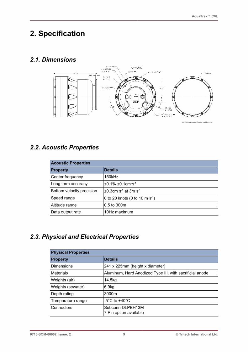
2.1. Dimensions
All dimensions are in mm, not to scale
2.2. Acoustic Properties
Acoustic PropertiesProperty DetailsCenter frequency 150kHzLong term accuracy ±0.1% ±0.1cm·s-1
Bottom velocity precision ±0.3cm·s-1 at 3m·s-1
Speed range 0 to 20 knots (0 to 10 m·s-1)Altitude range 0.5 to 300mData output rate 10Hz maximum
2.3. Physical and Electrical Properties
Physical PropertiesProperty DetailsDimensions 241 x 225mm (height x diameter)Materials Aluminum, Hard Anodized Type III, with sacrificial anodeWeights (air) 14.5kgWeights (sewater) 6.9kgDepth rating 3000mTemperature range -5°C to +40°CConnectors Subconn DLPBH13M
7 Pin option available

Specification AquaTrak™ CVL
0713-SOM-00002, Issue: 2 10 © Tritech International Ltd.
Electrical PropertiesProperty DetailsInput voltage 18 to 75 VDCPower consumption 10-12W average
(23W maximum @ 300m altitude and maximum update rate)Inrush current 1.7A @ 24VDC

AquaTrak™ CVL
0713-SOM-00002, Issue: 2 11 © Tritech International Ltd.
3. Installation
3.1. Electrical
The CVL includes a wide input range, isolated DC/DC power supply. The CVL supportssimultaneous 100Mbps Ethernet and serial communication. The CVL can be factoryconfigured for either full-duplex RS232 or half-duplex RS485 communication. Serialcommunication ground is isolated from both power ground and the shield.
See Section 2.3, “Physical and Electrical Properties” for more details on the powerrequirements of the AquaTrak™ CVL.
3.1.1. Bulkhead connection pinout diagram
1 2 3
7 6
8 9
13 12
1110
5 4
Male Bulkhead face view
Pin Signal1 GND2 SHIELD3 TRIGGER-4 RS485 + / RS232 TX5 RS485 - / RS232 RX6 COMMS GND7 N/C8 ETH TX-9 ETH TX+10 ETH RX-11 ETH RX+12 POWER13 TRIGGER+

Installation AquaTrak™ CVL
0713-SOM-00002, Issue: 2 12 © Tritech International Ltd.
3.1.2. Test Cable
BROWN - 24AWG
WHITE/BROWN - 24AWG
BLUE - 24AWG
WHITE/BLUE-24AWG
ORANGE - 24AWG
WHITE/ORANGE - 24AWG
GREEN - 24AWG
WHITE/GREEN - 24AWG
WHITE - 20AWG
GREEN - 20AWG
ORANGE - 20AWG
RED - 20 AWG
BLACK - 20AWG GND (BLK)
PWR 18-75 VDC (RED)
SHIELD (WHT)
RS232
100Mbs ETHERNET (EIA/TIA 568B)
TRIGGER
GND (BLK)
PWR 18-75 VDC (RED)
SHIELD (WHT)
N/C
LENGTH = 1m
DLPIL13FFACEVIEW
WM 1855-ND
123
76
89
1312
11 10
54
123
76
89
1312
11 10
54
112
213
3456789
1011
3
2
5
1
4
6
7
8
9
2
1
6
3
4
5
7
8
1
2
12
5 9
4
3
2
1
8
7
6
5 9
4
3
2
1
8
7
6
Figure 3.1. AquaTrak™ CVL Test Cable Schematic
DB-9 SERIAL PINOUTPIN SIGNAL1 N/C2 RX3 TX4 N/C5 GND6 N/C7 N/C8 N/C9 N/C
CAT 5 PINOUTPIN SIGNAL1 A+2 A-3 B+4 N/C5 N/C6 B-7 N/C8 N/C
TRIGGER PINOUTPIN SIGNAL1 +2 -
3.1.3. Triggering
The CVL accepts a RS422 level, differential trigger input. It does not provide a trigger output.The trigger signal is isolated from power-ground (PIN #1 – GND), but is common withcommunications ground (PIN #6 – COMMS GND).
3.1.4. Serial Communication
Unless otherwise requested, the serial communication will be defaulted to the followingsettings:
• 57600 baud

Installation AquaTrak™ CVL
0713-SOM-00002, Issue: 2 13 © Tritech International Ltd.
• 8 data bits
• 1 stop bit
• no parity
• no flow control
The Baud rate can be changed using the serial-speed command. Please refer toSection 4.3, “Commands” for more details.
3.2. Mechanical
3.2.1. Mounting
The AquaTrak™ CVL is mounted by the top flange with four M8 or 5/16” bolts. The CVLarray face should point down, towards the seabed, with the top alignment dowel slot orientedtowards the primary direction of travel.There are two methods available for accurately aligning the CVL with a bracket:
1. Method 1 uses the top internal bore of 112mm diameter and the 6mm dowel alignment slot
2. Method 2 uses two 3/8 Inch dowels as shown in Figure 3.2, “Alignment Methods”
Figure 3.2. Alignment Methods

Installation AquaTrak™ CVL
0713-SOM-00002, Issue: 2 14 © Tritech International Ltd.
3.2.2. Cables
The mating cable for the CVL is a Subconn DLPIL13F wet-mate low profile power/Ethernetconnector. Always follow proper handling procedures when mating and de-mating theconnector. Use only Molykote 44 to lubricate the connector.
Always ensure that the restraining strap LPB-STRAP is in place after connecting the cable.See mating of the cable and CVL in Figure 3.3, “CVL and Mating cable”below.
Figure 3.3. CVL and Mating cable

AquaTrak™ CVL
0713-SOM-00002, Issue: 2 15 © Tritech International Ltd.
4. OperationWarningThe CVL must be fully immersed in water before starting the unit pinging. Failureto do so will damage the CVL.
WarningWhen retrieving the CVL from water, pinging must be stopped prior to it surfacing.Failure to do so will damage the CVL.
4.1. Software VersionThe instructions within this manual apply to any AquaTrak™ CVL unit with software version1.2.3 or above. To find out the version of software installed on your CVL you can performone, or all, of the following:
1. Connect to your CVL and use the version command
2. Check the Build Record Sheet
3. Contact Tritech International Ltd with the Serial Number of your CVL
4.2. Software Interface
Communication with CVL
The CVL provides command and control via a command-line interface (CLI). This CLI isavailable via Telnet (on TCP port 4444), or serial communications (RS-232 or RS-485) ifsupplied.
Each CVL has a factory default static IP address of 192.168.0.100 but can also take ona DHCP-assigned or alternate static IP address.
The CLI client must terminate each command with either a carriage return character or acarriage return followed by a line feed.The CVL responds to each command issued to it. Every response from the CVL is terminatedby carriage return and line feed:
• If a line of the response text starts with “error” (optionally followed by some descriptivetext), it indicates failed command execution
• If a line of the response text starts with “warning” (optionally followed by some descriptivetext), it indicates successful command execution, but that there was an unexpectedcondition
• Any other response, including an empty response, indicates successful commandexecution
When the CVL software can accept the next command, it issues its command prompt,“cvl>˽” (one trailing blank character)

Operation AquaTrak™ CVL
0713-SOM-00002, Issue: 2 16 © Tritech International Ltd.
CLI Client Type
The CVL operates a Telnet server but can accept either Telnet or raw TCP connections. Thisis convenient for supporting manual or automatic clients:
• Manual client – In this case, a user submits commands to the CVL. A Telnet or serialconnection is recommended as it allows for command-line recall and editing
• Automatic client – In this case, a program submits commands to the CVL. A raw TCPconnection is recommended. Such a program should discard the few bytes of binary datathat it receives upon initial connection (before the first prompt). These bytes are part of theTelnet protocol and can be ignored. No other Telnet-related data will follow
System Modes
The CVL can be in one of two modes:
1. off: No sonar pulses are being transmitted, and no velocity calculations are beingperformed. This is the default start-up mode
2. on: Sonar pulses are being transmitted, and velocity calculations are being performed
Table 3 indicates which CLI commands are valid in which modes.
Table 4.1. CVL Commands
ModeCommandoff on
alarm-leak yes yesalarm-pressure yes yesaltitude yes yesaquatrak-endpoint yes read mode onlyaquatrak-status yes yesdata-received yes yesexternal-trigger yes read mode onlyhelp yes yesmode yes yesmonitor yes yesquit yes yesrotation-offset yes yessafe-mode yes yes1
serial-speed yes yesspeed-of-sound yes yessystem-health-check yes noversion yes yes
1 Note: Applying safe-mode while the mode is on will automatically change the mode to off.The mode will need to be reset to on before data can be obtained from the CVL.

Operation AquaTrak™ CVL
0713-SOM-00002, Issue: 2 17 © Tritech International Ltd.
4.3. CommandsSome commands can be used to either write or read CVL settings. If such a command issubmitted with parameters, it writes the corresponding settings. If the command is submittedwithout parameters, it reads and reports the current values of those settings. Commanddocumentation conventions include:
• Command syntax is written in bold fixed width font
• Factory default settings are preceded by a † symbol
• Text within square brackets ( [ ] ) describe optional components of a command’s syntax
• A vertical bar (|) represents the OR operator
• An italicized identifier represents an unspecified value
• A non-italicized identifier represents a specific value
4.3.1. alarm-leakThis will report an on message should the internal sensors detect water ingress. In the eventof this confirmation the CVL should be powered down, removed from its installation andimmediately inspected for damage.
† alarm-leak off
4.3.2. alarm-pressureThis will report an on message should the internal sensors detect an abnormality in theinternal environmental pressure. This could indicate a loss of integrity and so the unit shouldbe powered down, removed from its installation and inspected for damage.
† alarm-pressure off
4.3.3. altitudealtitude [altitude-m | auto]
Sets or reports the nominal altitude above the seabed, in metres. If “auto” is specified, theCVL detects the altitude automatically.
† altitude auto
4.3.4. aquatrak-endpointaquatrak-endpoint [ip-address:port | none]
Sets or reports the endpoint (IP address and port) of the internal CVL server. The endpointmust be assigned (that is, not set to “none”) in order to use “mode on”. The endpoint shouldnormally be set to 10.0.100.130:4500.
†aquatrak-endpoint 10.0.100.130:4500
4.3.5. aquatrak-statusaquatrak-status

Operation AquaTrak™ CVL
0713-SOM-00002, Issue: 2 18 © Tritech International Ltd.
Reports the status of the connection to the internal CVL server. If the “aquatrak-endpoint”command value is set to 10.0.100.130:4500, the connection status should always be“connected”.
4.3.6. data-receiveddata-received
Reports whether the CVL data reception mechanism has functioned since power up. If theCVL is configured correctly, the data-received command should report “true”. If not, the CVLshould be power cycled.
4.3.7. external-triggerexternal-trigger [on | off]
Sets or reports the status of the CVL external trigger mechanism. If set to “on”, the CVLtransmits each pulse only on the rising edge of the CVL trigger input. If triggered toofrequently, the CVL ignores some triggers as necessary.
4.3.8. helphelp
Reports all commands (and their parameters) that are available.
4.3.9. modemode [on | off]
Sets or reports the current system mode. Setting the mode to “on” causes the CVL to starttransmitting sonar pulses and start performing velocity measurements. Setting the mode to“off” causes the CVL to stop these activities.
See the section called “System Modes” for more information.
WarningThe CVL must be fully immersed in water when setting the mode to “on”. Failureto do so can damage the CVL.
The system mode is “off” upon power-up. See the “safe-mode” command for moreinformation.
†mode off
4.3.10. monitormonitor velocity | altitude | pd0 | pd4 | pd6 | pd11 | pd13 | alarm-
leak | alarm-pressure | noise-floor
Reports information on the specified activity as available, in real-time. The reporting stopswhen the client transmits another carriage return. An automatic client may establish multipleconnections to the CVL to monitor multiple activities.
Monitoring of each activity behaves as follows:

Operation AquaTrak™ CVL
0713-SOM-00002, Issue: 2 19 © Tritech International Ltd.
• velocity – Report each velocity as calculated, in metres per second. Surge and swayare reported, in that order, separated by white space.
• altitude – Report each altitude as calculated, in metres
• pd0
• pd4
• pd6 – Report each velocity as calculated, in PD6 format. Because the CVL measures onlyvelocity relative to the seabed (not relative to the water column), only the “:BI” message isprovided, containing the X- and Y-axis velocities. The Z-axis and error velocities are bothreported as 0.
• pd11 – Report each velocity as calculated, in PD11 format. Because the CVL does nothave a heading sensor, the course value in the $PRDIH message is omitted.
• pd13
• alarm-leak - Continuously reports the status of the alarm-leak sensor
• alarm-pressure - Continuously reports the status of the alarm-pressure sensor
• noise-floor
4.3.11. quitquit
Closes the communication session and terminates the connection (not applicable to the serialinterface).
4.3.12. rotation-offsetrotation-offset [ degree ]
Applies a rotational offset to the CVL data outputs.
Table 4.2. CVL Rotation
FORWARD
STARBOARD
Y
X
FORWARD
STARBOARD
Y
X
Orientation with 0° offset Orientation with a -45° offset applied
A -45° offset should be used to ensure full compatibility when outputting the PD6 outputformat.
†rotation-offset -45

Operation AquaTrak™ CVL
0713-SOM-00002, Issue: 2 20 © Tritech International Ltd.
4.3.13. safe-modesafe-mode [on | on-restart | off]
Sets or returns the current safe mode. The safe mode affects system behaviour as follows:
• safe-mode on – The system disallows setting the mode to “on” at any time, which impliesthat it is not transmitting sonar pulses
• safe-mode on-restart – The system starts with the mode set to “off”, which impliesthat it is not transmitting sonar pulses upon system start
• safe-mode off – The system starts in the mode it was in during the last shutdown, whichimplies that it may be transmitting sonar pulses
To help avoid unintentional sonar pulse transmission, safe mode should be set to “on-restart”or “on” whenever possible.
†safe-mode on
4.3.14. serial-speedserial-speed [9600 | 19200 | 38400 | 57600 | 115200]
Sets, or confirms, the Baud rate being used by the Serial interfaces. Some data outputs willoverride this setting as they have a preset communications profile.
NoteThe Baud rate for the serial connection can only be set via the serial connectionitself. It is not possible to connect using Ethernet and alter the Serial connection.
†serial-speed 57600
4.3.15. speed-of-soundspeed-of-sound [value]
Sets, or confirms the speed of sound being used by the CVL.
4.3.16. system-health-checksystem-health-check
Performs a health check of the CVL and re-initialises the system. The health check can onlybe performed when the mode has been set to off.An example output is given below:
starting health check
connecting... pass
testing-connection... pass
testing-channel-sync... pass
initializing device?
health check - successful
4.3.17. version
Reports the version of the CVL software.

AquaTrak™ CVL
0713-SOM-00002, Issue: 2 21 © Tritech International Ltd.
5. Getting StartedThe CVL uses a Command-Line-Interface (CLI) for control and monitoring. A Telnet client,such as PuTTY is required to access the CVL CLI. It is assumed that the user has connectedpower and Ethernet to the CVL as described in the Product Manual. See Table 5.1, “CVLReference information” for useful reference information.
Table 5.1. CVL Reference information
SPECIFICATION DESCRIPTIONStatic IP Address 192.168.0.100Port 4444Protocol Telnet
5.1. Initial Connection
Connect to the CVL using the supplied static IP address, or your local network’s DHCPassigned address. Once connected, the CLI prompt appears:
cvl>
Type the help command for a list of the available commands, and the inputs they support:
cvl> help
Available commands:
alarm-leak
alarm-pressure
altitude <value> | auto
aquatrak-endpoint [<ip-address>:<port>]
aquatrak-status
data-received
external-trigger on | off
help
mode off | on
monitor velocity | altitude | pd0 | pd4 | pd6 | pd11 | pd13
| alarm-leak | alarm-pressure | noise-floor
quit
safe-mode on | on-restart | off
serial-speed 9600 | 19200 | 38400 | 57600 | 115200
speed-of-sound <value>
system-health-check
version
Check that data is being generated by the CVL with the data-received command:
cvl> data-received
true
If this command returns false, the CVL must be power-cycled.

Getting Started AquaTrak™ CVL
0713-SOM-00002, Issue: 2 22 © Tritech International Ltd.
5.2. Altitude ConfigurationThe operating state can be configured using the altitude command. This commandaccepts either the nominal altitude of the CVL from sea-floor or the parameter, auto.When the CVL is operating with altitude auto, the range from bottom is determinedautomatically and the CVL settings are adjusted accordingly. Set the altitude to auto:
cvl> altitude auto
cvl> altitude
auto
If operating in a shallow test-tank, it is better to use a set altitude. In either configuration, theminimum altitude at which the CVL reports correct velocities is 0.5 metres.
5.3. Enable PingingBefore continuing, ensure the CVL is submerged in water. To do otherwise may damagethe CVL.
The CVL must exit safe-mode before pinging can be enabled. When disabling safe-mode,it is best practice to use on-restart, which places the CVL back into safe-mode if it ispower-cycled. Otherwise the CVL may resume pinging the next time it is powered.Set safe-mode to on-restart and the enable pinging by setting the mode to on:
cvl> safe-mode on-restart
cvl> mode on
5.4. Monitor the OutputThe CVL outputs the calculated velocities in a variety of different formats such as PD6, PD11,or space-separated values (see the Interface Control Document (ICD) for a description ofeach). To view the output of the CVL, use the monitor command, supplying the stringidentifying the format desired. While monitoring is enabled, the CVL transmits each estimateas it is generated. To exit monitoring, press the Enter key.Monitor the velocities in the PD11 format:
cvl> monitor pd11
$PRDIG,H,,P,,R,,D,*46
$PRDIH,R,0.51,S,0.019,C,*39
$PRDII,S,,C,*56
$PRDIG,H,,P,,R,,D,*46
$PRDIH,R,0.49,S,0.103,C,*3A
$PRDII,S,,C,*56
cvl>
5.5. Disable PingingBefore removing the CVL from water, disable pinging. To do otherwise may damage the CVL.

Getting Started AquaTrak™ CVL
0713-SOM-00002, Issue: 2 23 © Tritech International Ltd.
Setting the mode to off disables pinging. Then re-enabling safe-mode is recommended.
cvl> mode off
cvl> safe-mode on

AquaTrak™ CVL
0713-SOM-00002, Issue: 2 24 © Tritech International Ltd.
6. Restore to Factory DefaultThe CVL can be restored to the factory default settings through the admin tool. The admintool can be accessed using an SSH client such as PuTTY. It is assumed that the user hasconnected power and Ethernet to the CVL as described in the ICD.
Table 6.1. Admin-Tool Reference information
SPECIFICATION DESCRIPTIONStatic IP Address 192.168.0.100Port 22Protocol SSHUsername adminPassword Admin
Connect to the CVL using the supplied static IP address, or your local network’s DHCPassigned address. Once connected, you are then prompted for a username and password.Use those provided in Table 6.1, “Admin-Tool Reference information”.
##############################################
# #
# Kraken Appliance | Administration Tool #
# #
##############################################
Thu Aug 4 13:38:59 UTC 2016
System Temperatures:
Core 0: +35.0°C (high = +110.0°C, crit = +110.0°C)
Core 1: +34.0°C (high = +110.0°C, crit = +110.0°C)
Core 2: +37.0°C (high = +110.0°C, crit = +110.0°C)
Core 3: +37.0°C (high = +110.0°C, crit = +110.0°C)
Partition Availability and Usage:
/dev/sda4 3.7G 232M 3.2G 7% /kraken
/dev/sda5 969M 58M 845M 7% /kraken/images
##############################################
Please select from the following options:
1) Upgrade Firmware 4) Factory Reset 7) Shutdown
2) Configure eth1 5) Upgrade Image 8) Refresh
3) Set NTP Server 6) Reboot 9) Quit
Option #:
Selecting option 4 initiates the factory reset process:
WARNING: This will erase all settings and recorded sonar data from this device
Proceed with factory reset? [y/N] y
Stopping cvl service...
[sudo] password for admin:
* stop: Job stopped: cvl
* start: Starting job: cvl
Factory image restored successfully

AquaTrak™ CVL
0713-SOM-00002, Issue: 2 25 © Tritech International Ltd.
Appendix A. Output Formats
A.1. Industry Standard formatsThe AquaTrak™ CVL can output the PD6 and PD11 data formats, which contain bottom-track instrument referenced data.
PD0 format
This is a binary data format that is not human readable. More details are available uponrequest.
PD4 format
This is a binary data format that is not human readable.
Table A.1.
BIT POSITION
Byte 7 6 5 4 3 2 1 0
1 DVL DATA ID 7Dh
2 DATA STRUCTURE
3 LSB
4NO. OF BYTES
MSB
5 SYSTEM CONFIG
6 LSB
7X-VEL BTM
MSB
8 LSB
9Y-VEL BTM
MSB
10 LSB
11Z-VEL BTM
MSB
12 LSB
13E-VEL BTM
MSB
14 LSB
15BM1 RNG TO BTM
MSB
16 LSB
17BM2 RNG TO BTM
MSB
18 LSB
19BM3 RNG TO BTM
MSB
20 LSB
21BM4 RNG TO BTM
MSB
22 BOTTOM STATUS
23 LSB
24X-VEL REF LAYER
MSB
25
26Y-VEL REF LAYER
27
28Z-VEL REF LAYER

Output Formats AquaTrak™ CVL
0713-SOM-00002, Issue: 2 26 © Tritech International Ltd.
BIT POSITION
Byte 7 6 5 4 3 2 1 0 29
30E-VEL REF LAYER
31
32REF LAYER START
33
34REF LAYER END
35 REF LAYER STATUS
36 TOFP-HOUR
37 TOFP-MINUTE
38 TOFP-SECOND
39 TOFP-HUNDREDTHS
30
41BIT RESULTS
42
43SPEED OF SOUND
44
45TEMPERATURE
46
47CHECKSUM
PD6 format
Table A.2.
Line number Details
1 SYSTEM ATTITUDE DATA
:SA,±PP.PP,±RR.RR,HHH.HH<CR><LF>
2 TIMING AND SCALING DATA
:TS,YYMMDDHHmmsshh,SS.S,+TT.T,DDDD.D,CCCC.C,BBB<CR><LF>
• YYMMDDHHmmsshh = Year, month, day, hour, minute, second, hundredths of seconds
• SS.S = Salinity in parts per thousand (ppt) (always zero)
• TT.TT = Temperature in °C (always zero)
• DDDD.D = Depth of transducer face in meters (always zero)
• CCCC.C = Speed of sound in meters per second
• BBB = Built-in Test (BIT) result code (always zero)
3 WATER-MASS, INSTRUMENT-REFERENCED VELOCITY DATA
:WI,±XXXXX,±YYYYY,±ZZZZZ,±EEEEE,S<CR><LF>
4 WATER-MASS, SHIP-REFERENCED VELOCITY DATA
:WS,±TTTTT,±LLLLL,±NNNNN,S<CR><LF>
5 WATER-MASS EARTH-REFERENCED VELOCITY DATA
:WE,±EEEEE,±NNNNN,±UUUUU,S<CR><LF>
6 WATER-MASS, EARTH-REFERENCED DISTANCED DATA

Output Formats AquaTrak™ CVL
0713-SOM-00002, Issue: 2 27 © Tritech International Ltd.
Line number Details
:WD,±EEEEEEEE.EE,±NNNNNNNN.NN,±UUUUUUUU.UU,DDDD.DD,TTT.TT<CR><LF>
7 BOTTOM-TRACK, INSTRUMENT-REFERENCED VELOCITY DATA
:BI,±XXXXX,±YYYYY,±ZZZZZ,±EEEEE,S,<CR><LF>
• ±XXXXX = X-axis velocity in mm·s-1
• ±YYYYY = Y-axis velocity in mm·s-1
• ±ZZZZZ = Z-axis velocity in mm·s-1 (always zero)
• EEEEE = Error velocity data in mm·s-1 (always zero)
• S = Status of velocity (A = good, V = bad)
8 BOTTOM-TRACK, SHIP-REFERENCED VELOCITY DATA
:BS,±TTTTT,±LLLLL,±NNNNN,S<CR><LF>
• ±TTTTT = Transverse vel. data in mm/s
• ±LLLLL = Longitudinal vel. data in mm/s
• ±NNNNN = Normal velocity data in mm/s
• S = Status of velocity data (A = good, V = bad)
9 BOTTOM-TRACK, EARTH-REFERENCED VELOCITY DATA
:BE,±EEEEE,±NNNNN,±UUUUU,S<CR><LF>
10 BOTTOM-TRACK, EARTH-REFERENCED DISTANCE DATA
:BD,±EEEEEEEE.EE,±NNNNNNNN.NN,±UUUUUUUU.UU,DDDD.DD,TTT.TT<CR><LF>
Only the :TS and :BI lines will contain data from the CVL. All the data fields for the otherlines contain zero (0) data.
Example CVL output:
:SA, +0.00, +0.00, 0.00
:TS,16060208211366, 0.0, +0.0, 0.0,1500.0, 0
:WI, +0, +0, +0, +0,V
:WS, +0, +0, +0,V
:WE, +0, +0, +0,V
:WD, +0.00, +0.00, +0.00, 0.00, 0.00
:BI, +5, +1, +0, +0,A
:BS, +0, +0, +0,V
:BE, +0, +0, +0,V
:BD, +0.00, +0.00, +0.00, 0.51, 0.00
PD11 format
Table A.3.
Line number Details
1 SENSOR DATA
$PRDIG,H,w.w,P,x.x,R,y.y,D,z.z*hh<CR><LF>

Output Formats AquaTrak™ CVL
0713-SOM-00002, Issue: 2 28 © Tritech International Ltd.
Line number Details
2 BOTTOM-TRACK NAVIGATIONAL DATA
$PRDIH,R,x.x,S,y.y,C,z.z,*hh<CR><LF>
• R,x.x = Range to bottom (m)
• S,y.y = Speed relative to ground (m·s-1)
• C,z.z = Course over ground (will always be empty)
• hh = Checksum
3 CURRENT-REFERENCED NAVIGATIONAL DATA
$PRDII,S,x.x,C,y.y*hh<CR><LF>
Example CVL output:
$PRDIG,H,,P,,R,,D,*46
$PRDIH,R,0.51,S,0.136,C,*35
$PRDII,S,,C,*56
PD13 format
Table A.4.
Line number Details
1 SYSTEM ATTITUDE DATA
:SA,±PP.PP,±RR.RR,HHH.HH<CR><LF>
2 TIMING AND SCALING DATA
:TS,YYMMDDHHmmsshh,SS.S,+TT.T,DDDD.D,CCCC.C,BBB<CR><LF>
• YYMMDDHHmmsshh = Year, month, day, hour, minute, second, hundredths of seconds
• SS.S = Salinity in parts per thousand (ppt) (always zero)
• TT.TT = Temperature in °C (always zero)
• DDDD.D = Depth of transducer face in meters (always zero)
• CCCC.C = Speed of sound in meters per second
• BBB = Built-in Test (BIT) result code (always zero)
3 PRESSURE AND RANGE TO BOTTOM DATA
:RA,PPP.PP,RRRR.RR,RRRR.RR,RRRR.RR,RRRR.RR<CR><LF>
4 WATER-MASS, INSTRUMENT-REFERENCED VELOCITY DATA
:WI,±XXXXX,±YYYYY,±ZZZZZ,±EEEEE,S<CR><LF>
5 WATER-MASS, SHIP-REFERENCED VELOCITY DATA
:WS,±TTTTT,±LLLLL,±NNNNN,S<CR><LF>
6 WATER-MASS EARTH-REFERENCED VELOCITY DATA
:WE,±EEEEE,±NNNNN,±UUUUU,S<CR><LF>
7 WATER-MASS, EARTH-REFERENCED DISTANCED DATA

Output Formats AquaTrak™ CVL
0713-SOM-00002, Issue: 2 29 © Tritech International Ltd.
Line number Details
:WD,±EEEEEEEE.EE,±NNNNNNNN.NN,±UUUUUUUU.UU,DDDD.DD,TTT.TT<CR><LF>
8 BOTTOM-TRACK, INSTRUMENT-REFERENCED VELOCITY DATA
:BI,±XXXXX,±YYYYY,±ZZZZZ,±EEEEE,S,<CR><LF>
• ±XXXXX = X-axis velocity in mm·s-1
• ±YYYYY = Y-axis velocity in mm·s-1
• ±ZZZZZ = Z-axis velocity in mm·s-1 (always zero)
• EEEEE = Error velocity data in mm·s-1 (always zero)
• S = Status of velocity (A = good, V = bad)
9 BOTTOM-TRACK, SHIP-REFERENCED VELOCITY DATA
:BS,±TTTTT,±LLLLL,±NNNNN,S<CR><LF>
10 BOTTOM-TRACK, EARTH-REFERENCED VELOCITY DATA
:BE,±EEEEE,±NNNNN,±UUUUU,S<CR><LF>
11 BOTTOM-TRACK, EARTH-REFERENCED DISTANCE DATA
:BD,±EEEEEEEE.EE,±NNNNNNNN.NN,±UUUUUUUU.UU,DDDD.DD,TTT.TT<CR><LF>
Only the :TS and :BI lines will contain data from the CVL. All the data fields for the otherlines contain zero (0) data.
Example CVL output:
:SA, +0.00, +0.00, 0.00
:TS,16060208245869, 0.0, +0.0, 0.0,1500.0, 0
:RA, 0.00, 0.51, 0.51, 0.51, 0.51
:WI, +0, +0, +0, +0,V
:WS, +0, +0, +0,V
:WE, +0, +0, +0,V
:WD, +0.00, +0.00, +0.00, 0.00, 0.00
:BI, -26, -10, +0, +0,A
:BS, +0, +0, +0,V
:BE, +0, +0, +0,V
:BD, +0.00, +0.00, +0.00, 0.51, 0.00
A.2. Proprietary formatsThe AquaTrak™ CVL also has several proprietary output formats. Further details of thedefinition of these outputs are available on request.
altitude
cvl> monitor altitude
altitude: 1.21
altitude: 1.62

Output Formats AquaTrak™ CVL
0713-SOM-00002, Issue: 2 30 © Tritech International Ltd.
noise-floor
cvl> monitor noise-floor
noise-floor: 3521558 4143570 3926082 3802606 4150980 1858309 2433204 1916663
noise-floor: 3532067 4144968 3931363 3809594 4143971 1867085 2430690 1921892
velocity
cvl> monitor velocity
velocity: -0.005 0.000
velocity: 0.000 0.005