aprs acoustic positioning reference sensor · gaps is a high performance integrated underwater...
TRANSCRIPT


APRS Acoustic Positioning Reference Sensor
AUV Autonomous Unmanned Vehicle
CBIT Continuous Built-In Test
DP Dynamic Positioning
FOG Fiber Optical Gyroscope
FPSO Floating Production Storage and Offloading
GAPS Global Acoustic Positioning System
GPS Global Positioning System
ICD Interface Control Document
IMU Inertial Measurement Unit
INS Inertial Navigation System
ITS iXblue Telegram Service
MMI Man Machine Interface
MRU Motion Reference Unit
NIS Noise Isotropic Spectrum
NMEA National Marine Electronics Association
OBC Ocean Bottom Cable
ROV Remotely Operated Vehicle
RTK Real-Time Kinematics
SNR Signal to Noise Ratio
USBL Ultra Short Base Line

1 IXBLUE CORPORATE DESCRIPTION ................................................................................. 4
1.1 THE COMPANY ............................................................................................................................ 4
1.2 WORLDWIDE PRESENCE .............................................................................................................. 5
1.3 ACOUSTIC PRODUCTS DIVISION ................................................................................................... 7
2 GAPS DESCRIPTION ....................................................................................................... 8
2.1 PRODUCT DESCRIPTION ............................................................................................................... 8
2.2 BASIC PRINCIPLE......................................................................................................................... 9
2.3 COMPONENTS ........................................................................................................................... 10
2.4 GAPS ADVANTAGES .................................................................................................................. 10
2.5 PACKING AND SHIPPING ............................................................................................................. 12
2.6 GAPS IV, THE LATEST PRODUCT’S GENERATION ......................................................................... 12
3 GAPS APPLICATIONS ................................................................................................... 13
4 GAPS DIAGRAM ASSEMBLY .......................................................................................... 14
5 GAPS FUNCTIONALITIES............................................................................................... 15
5.1 SUBSEA POSITIONING ................................................................................................................ 15
5.2 ITS – IXBLUE TELEGRAM SERVICE ............................................................................................ 15
5.3 SURFACE NAVIGATION AND ATTITUDE COMPENSATION ................................................................ 16
5.4 L/USBL/INS FOR DYNAMIC POSITIONING .................................................................................. 17
5.5 SOUND VELOCITY PROFILE AND RAY BENDING COMPENSATION .................................................... 18
5.6 NOISE SPECTRUM DISPLAY ........................................................................................................ 18
5.7 TELECOMMAND ......................................................................................................................... 19
5.8 PING STACKING ......................................................................................................................... 19
5.9 INPUT/OUTPUT .......................................................................................................................... 20
5.10 GAPS WEB MMI ........................................................................................................................ 21
5.11 DELPH ROADMAP ................................................................................................................... 22
5.12 INTERFACING TO NAVIGATION SOFTWARE ................................................................................... 25
6 GAPS + INS NAVIGATION ............................................................................................. 26
7 COMPATIBLE TRANSPONDERS ..................................................................................... 28
8 GAPS DEPLOYMENT METHODS ..................................................................................... 30
8.1 POLE MOUNT (DRAWING PROVIDED ON REQUEST) ....................................................................... 30
8.2 MOON POOL .............................................................................................................................. 31
8.3 IXBLUE HOISITING SYSTEM ......................................................................................................... 31
8.4 EXISTING HOISITING SYSTEM ...................................................................................................... 32
8.5 REMOTE TOWED PLATFORM ....................................................................................................... 32
8.6 SURFACE BUOY ......................................................................................................................... 33
8.7 SURFACE DRONE (USV) ............................................................................................................ 33
9 INTERFACING .............................................................................................................. 34
10 GAPS REPEATER BOX .................................................................................................. 35
11 GAPS SPECIFICATION .................................................................................................. 36

11.1 SYSTEM (GAPS + CABLE + BOX) ................................................................................................ 36
11.2 GAPS HEAD .............................................................................................................................. 38
11.3 GAPS BOX ............................................................................................................................... 39
11.4 MAIN CABLE ............................................................................................................................. 40
12 GAPS PERFORMANCES ................................................................................................ 41
12.1 MAXIMUM RANGE ...................................................................................................................... 41
12.2 BEARING ACCURACY ................................................................................................................. 42
12.3 POSITIONING ACCURACY ........................................................................................................... 42
12.4 MAXIMUM RANGE DEPENDING ON BEACONS ................................................................................ 43
12.5 POSITIONING ACCURACY DEPENDING ON BEACONS ..................................................................... 44
12.6 POSITIONING ACCURACY DEPENDING ON ELEVATION ................................................................... 45
12.7 PERFORMANCES FOR DYNAMIC POSITIONING ............................................................................. 46
12.8 OBTAINED PERFORMANCES IN SHALLOW WATER (VERTICAL CONDITIONS) .................................... 47
12.9 OBTAINED PERFORMANCES IN SHALLOW WATER (HORIZONTAL TRACKING) .................................. 49
13 LIFE CYCLE ................................................................................................................. 50
13.1 PACKAGING, HANDLING, STORAGE, TRANSPORTATION REQUIREMENTS ...................................... 50
13.2 CALIBRATION ............................................................................................................................ 50
13.3 BUILT-IN TEST ........................................................................................................................... 50
13.4 RELIABILITY & MAINTAINABILITY ................................................................................................ 50
13.5 HYDROPHONE/LEG REPLACEMENT ............................................................................................. 51
14 REFERENCES .............................................................................................................. 52
15 DRAWINGS .................................................................................................................. 54

iXblue is an independent group and a leading global manufacturer of products, integrated solutions and systems for navigation, mapping, control and measurement technologies. iXblue incorporates a wide range of capabilities to deliver world leading solutions to the offshore, land, air, space, defense, industry and photonics market. For the past number of years iXblue has been implementing a sustained policy of growth and has expanded its core competencies and its capacity to offer system solutions for these markets.
Pioneers of cutting edge technology solutions, iXblue invents and offers solutions that are cost effective, time efficient, reliable and straightforward to use. iXblue offers a broad and unique range of complementary products built on the following key technologies:
FOGs (Fibre Optic Gyroscopes) and INS (Inertial Navigation Systems)
Underwater acoustic (USBL positioning, transducers and remote control)
Imagery and seafloor mapping (sonar, seismic, magnetic and data acquisition systems) iXblue comprises today six business units: navigation systems, photonics solutions, sea operations, acoustic systems, marine works and motion systems.
The name iXblue is synonymous with brand quality, its mastery of the inertial and sensor market, continuous innovation and best customer service. For each technology, iXblue is one of the rare highly skilled companies in its field. It benefits from important technological advantages in its research and development and from a policy of open communication and feedback from clients. These cutting edge products are very competitively priced, as iXblue does not have to pass on intermediary sensor purchase costs.

iXblue do also provide complete solutions to its customers, defining with them the solution that best fits their needs. The designed system can incorporate iXblue and/or third party equipment, hardware and software, fully integrated. The turnkey solution includes all the necessary services: engineering, installation and test, training, premium customer support and maintenance.
iXblue has been engaged for several years in a quality process to maximize the satisfaction of its customers. iXblue is certified ISO9001-2008.
Functional With a sustained growth, a staff of over 600 and a total of three quarters of turnover accounting for exports, iXblue has a true worldwide market presence.

A dedicated customer support department for helpline and on-field support is available worldwide 24 hours a day, all year round by telephone or email.
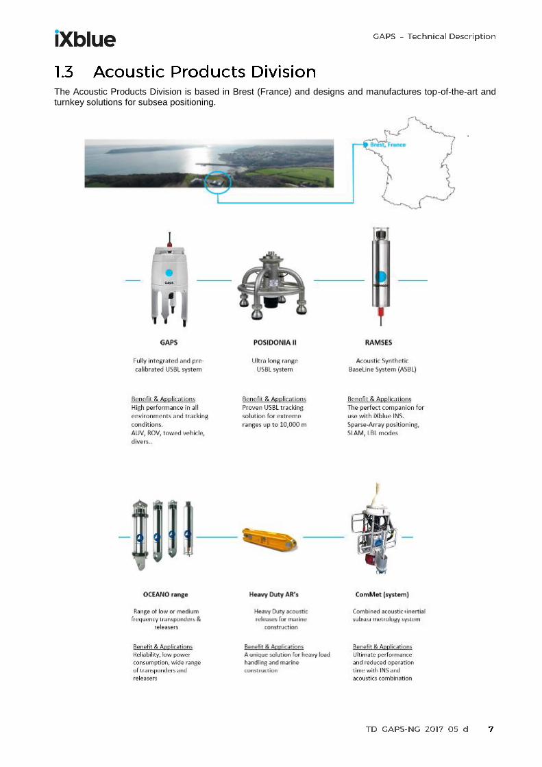
The Acoustic Products Division is based in Brest (France) and designs and manufactures top-of-the-art and turnkey solutions for subsea positioning.
.

Gaps is a high performance integrated underwater positioning solution which makes USBL (Ultra Short Base Line) underwater positioning extremely simple to operate from any vessel, using a portable and truly pre-calibrated USBL head coupled with internal INS (Inertial Navigation System) and GNSS. The Gaps also enables exchange data between the Gaps transceiver and the beacon using acoustic communication. Gaps measures the absolute position of one or more subsea objects or vehicles which can navigate at depths up to 4,000 meters, with 200 deg hemispherical coverage below the antenna. Depending on environmental conditions, the positioning accuracy is up to 0.06% of the slant range and the data rate is 500 bits/second for the acoustic communication. These objects or vehicles are located using acoustic transponders or beacons and a subsurface acoustic array (Gaps head) typically deployed under water below the ship hull or from any surface platform.
Gaps is used for tracking and communicating with subsea devices (ROVs, AUVs, structures, towfish, divers…) and for dynamic positioning applications when transponders are fixed on the seabed. The Gaps meets the needs of oil & gas, defense, marine construction, survey and scientific applications.
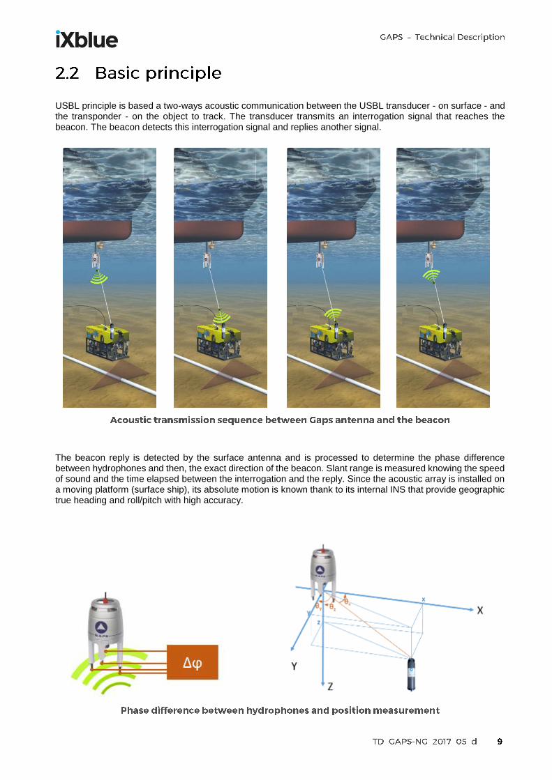
USBL principle is based a two-ways acoustic communication between the USBL transducer - on surface - and the transponder - on the object to track. The transducer transmits an interrogation signal that reaches the beacon. The beacon detects this interrogation signal and replies another signal.
The beacon reply is detected by the surface antenna and is processed to determine the phase difference between hydrophones and then, the exact direction of the beacon. Slant range is measured knowing the speed of sound and the time elapsed between the interrogation and the reply. Since the acoustic array is installed on a moving platform (surface ship), its absolute motion is known thank to its internal INS that provide geographic true heading and roll/pitch with high accuracy.

Gaps comprises, in a single lightweight housing (carbon fiber made), all required components to achieve USBL positioning including the INS. The system is plug and play, deployable in an instant, and can be operated immediately thanks to its pre-calibrated concept. The INS is the inertial navigation system composed of three Fiber Optic Gyroscopes (FOG) and three accelerometers mounted on orthogonal axis. The INS provides the exact position and attitude with very high level of accuracy and high update rates. Heading is provided with an accuracy of 0.01° seclat making it one of the best performing INS. The acoustic array is composed of one (1) transmission transducer and four (4) reception hydrophones. It ensures the sending of the acoustic triggering signal to the transponders and the receiving of their replies. The acoustic array of the Gaps is 3D: it has four receiving hydrophones on the vertices of a tetrahedron (four is the minimum number of hydrophone for unambiguous positioning in 3-D space). This design implies very good angular coverage (>200 degrees aperture below the acoustic antenna).
Taking advantage of its unique expertise in acoustic positioning and inertial sensors, iXblue introduces Gaps, the first acoustic + inertial integrated positioning system for marine and subsea applications. It is an all-in-one system which can provide at the same time the position of a surface vessel and of several subsea vehicles or divers. It also provides a very accurate heading and attitude for the surface vessel with the highest accuracy and unrivalled performances in shallow or extreme shallow water depth thanks to unique receiving antenna design and enhanced digital signal processing techniques. Gaps is a portable system (light weight and reduced size), does not require any complicated and time consuming installation (all-in-one pre-calibrated system), features very high performance thanks to data fusion of Acoustic, inertial and GNSS technologies and finally has no limit in terms of operation area (shallow and deep water, horizontal and vertical channel, short or long range).

Features
Compact, all-in-one USBL solution
High grade INS for ultimate performance
3D acoustic array geometry
Wideband modulation
Provide absolute georeferenced position for the beacon
Compatible with all major navigation suites
Easy to interface with subsea INS
DP mode: L/USBL/INS (PRS, MRU & Gyro all in one)
More than 500 available acoustic channels
Unified iXblue web interface
3D display software included (DELPH RoadMap)
Acoustic communication (ITS)
Benefits Rapid deployment
Operational cost savings
Pre-calibrated
Easy to install
Easy to operate
Accurate positioning
Robust performance
Flexible deployment operations
Horizontal tracking
Wireless subsea communication
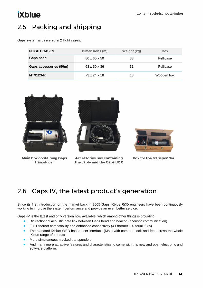
Gaps system is delivered in 2 flight cases.
FLIGHT CASES Dimensions (m) Weight (kg) Box
Gaps head
80 x 60 x 50 38 Pellicase
Gaps accessories (50m) 63 x 50 x 36 31 Pellicase
MT912S-R 73 x 24 x 18 13 Wooden box
Since its first introduction on the market back in 2005 Gaps iXblue R&D engineers have been continuously working to improve the system performance and provide an even better service. Gaps-IV is the latest and only version now available, which among other things is providing:
Bidirectionnal acoustic data link between Gaps head and beacon (acoustic communication)
Full Ethernet compatibility and enhanced connectivity (4 Ethernet + 4 serial I/O’s)
The standard iXblue WEB based user interface (MMI) with common look and feel across the whole iXblue range of product
More simultaneous tracked transponders
And many more attractive features and characteristics to come with this new and open electronic and software platform.

Oil & Gas Structure placement, ROV navigation, AUV & glider operations, towfish tracking, cable/pipe laying, diver tracking, exploration, drilling, DP, touch down positioning, mattress lay, plough/trench positioning, Out Of Straightness, BSR positioning, seismic (streamer, nodes, OBC), rig move, anchor positioning, riser positioning
Defense Diver tracking, AUV tracking, under hull inspection, imagery, mine counter measure
Scientific ROV, AUV, gliders and towfish tracking
Other Marine construction, cable laying, mining, seabed crawler positioning, touch down monitoring
Trenching
ROV tracking
Touch Down Monitoring
Structure placement
Cut to length
Pipeline crossing
Pipeline survey
Ocean Bottom Cable
AUV
Diver tracking
Glider
DP
Towed sonar
Drilling FPSO, Buoy Supported Riser Survey

Gaps is a fully integrated system which does not require any further third party equipment to be operated. A comprehensive but reduced list of equipment is provided with the system. Its compact size, light weight, operating versatility and pre-calibrated characteristics make it usable in almost any kind of tracking operation with very quick and easy deployment. A standard Gaps system requires the following components for a ready to use configuration:
1
This is the main part of the Gaps system, which comprises the acoustic array to communicate with the transponder(s) installed on the target(s), the INS for motion compensation and absolute georeferencing, and all electronics and signal processing.
2
Gaps Box designed to interface between the Gaps head and external peripherals. It includes power supply from mains & 28 Vdc, Ethernet connector, RS422 / 232 input/output and synchro in/out on BNC.
3
50 or 95 m long cable used to communicate with Gaps head. Possible options: ATEX, 95m and greater length using repeater Box.
4
A complete turnkey solution is available on option, including a GPS receiver, a ‘Y’ cable and a 15 m GPS cable.
5
Transponders are deployed on the vehicle or the object to track. Several models are available depending on the autonomy, the type of batteries and if an acoustic release is required.

The Gaps can simultaneously track several fixed or mobile transponders. Every model of transponder has different interrogation and reply codes. The combination of interrogation and reply code makes a unique address for one transponder. The maximum Gaps capacity:
- 40 beacons can be positioned simultaneously - 500 beacons can be declared in the system (only 40
simultaneously “in use”)
The Gaps offers the iXblue Telegram Service and the full benefit of underwater wireless communication technology between the Gaps transducer and the beacon in half-duplex mode (Gaps to beacon and beacon to Gaps). Tracking and communication are achieved simultaneously, using iXblue wideband telemetry modulation.
This can achieve a variety of communication tasks thanks to the user defined protocol:
- Broadcast information from a sensor to the surface - Change the configuration of the beacon - Get beacon status and internal sensor measurement (battery
voltage, pressure sensor…)
- Send/get data to/from host - Send position to a subsea INS The data rate is 500 bps and it includes a robust error detection and correction method. This enable to send or receives 160 bits per recurrence. The Doppler is +/- 6 knots.

Control/command AUVs Wirelessly send a position to a subsea INS
Collect data from any subsea sensor
Gaps enables simultaneous tracking and acoustic coms without the need to install dedicated modem transducer on the AUV or on the surface vessel. Gaps tracks, sends commands and receives AUV status, all with the same equipment.
For AUV and ROV applications, Gaps enables to wirelessly send a position to a subsea INS:
- Gaps estimates the position of the beacon (USBL)
- Gaps sends to the beacon its position
- The beacon broadcasts to the subsea INS the position
Any sensor can be interfaced to a subsea beacon. The beacon broadcasts through acoustic channel the measurements to the Gaps. It outputs the information on serial or Ethernet communication port.
Any Gaps IV can be updated to benefit from this new feature. Contact iXblue to know which models of beacons are compatible with this iXblue Telegram Service.
The Gaps is also an INS and can be used as such. If any sensor on the same mechanical structure than the Gaps requires to be compensated in heading, roll, pitch or position, one of the eight output of the system can be used to achieve this task. As an example, a multibeam that would be deployed on the same side pole than the Gaps could be interfaced to the INS of the Gaps and compensated in
heading/roll/pitch/heave and position.

Gaps is ready to be interfaced to any Dynamic Positioning system in order to ensure follow target mode (when transponder is on a subsea vehicle) or auto position mode (when transponders are deployed on the seabed.
Gaps becomes an Acoustic Positioning Reference Sensor (APRS) for the DP as well as a Motion Reference Unit (MRU) and a gyrocompass, all these functions being in the same equipment. Critical points are the positioning precision, the robustness to noise and information redundancy.
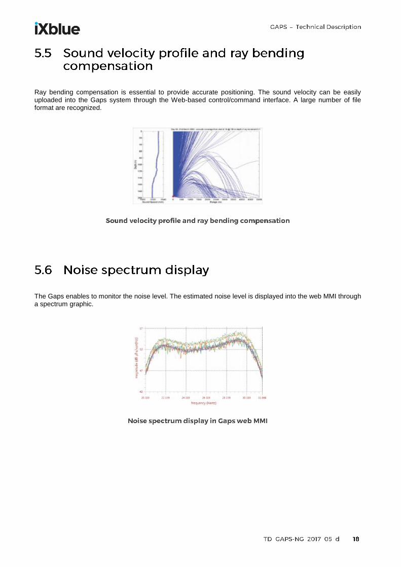
Ray bending compensation is essential to provide accurate positioning. The sound velocity can be easily uploaded into the Gaps system through the Web-based control/command interface. A large number of file format are recognized.
The Gaps enables to monitor the noise level. The estimated noise level is displayed into the web MMI through a spectrum graphic.

When used with RTA series, the Gaps is used to send release telecommands.
When operating Gaps with long slant ranges, the ping stacking enables to increase acoustic update rates whatever the water depth and the time required by the acoustic wave to propagate from the beacon to the Gaps transducer. Activating the ping stacking function enables to encapsulate several acoustic recurrences and have acoustic updates rates of 1 sec, whatever the water depth.

All communication to and from Gaps are achieved using industry standard NMEA0183 data telegram through the serial input/output ports, messages content is fully described in the user manual provided with the equipment. In addition to its standard proprietary communication protocol (“Gaps standard”) Gaps is featuring native compatibility with other iXblue sensors and subsystems (PHINS, RAMSES, etc..) and can emulate other industry standard protocols. This allows Gaps to smoothly interface to iXblue or already existing third party hardware / software, or easily interface to peripherals or main system such as DP engines. Examples of protocols for USBL positions:
Gaps Standard
HIPAP HPR 400, HPR418, HPRBCD
NAUTRONIX
iXblue USBL INS
POSIDONIA 6000
GPGGA Examples of protocols for INS positions and attitudes (inside the Gaps antenna):
HEHDT
GNSS like
GYROCOMPASS
NAVIGATION
OCTANS STANDARD
PHINS STANDARD

Gaps can be connected to a PC for configuration, installation and display purposes through a Web-based User Interface software. The Gaps web interface Gaps is used to:
Configure Gaps (input/output configuration, sound velocity profile, etc).
Control the position(s) of the transponder(s) and the status related to the quality of the positioning. User-friendly menu screens allow the operator to define Gaps setting before deployment in an instant. The use of the control system is not mandatory once Gaps is configured. Gaps keeps all its settings when powered off and resume its last behaviour when started up.
This Web-based control/command software is also used for maintenance purposes. All the firmware can be downloaded into the Gaps and does not require to open the Gaps housing. Alternatively and when Gaps is part of a system, it can be controlled/commanded using URL commands coming from a supervision software. The ICD (Interface Control Document) can be provided on request for the description of the commands.
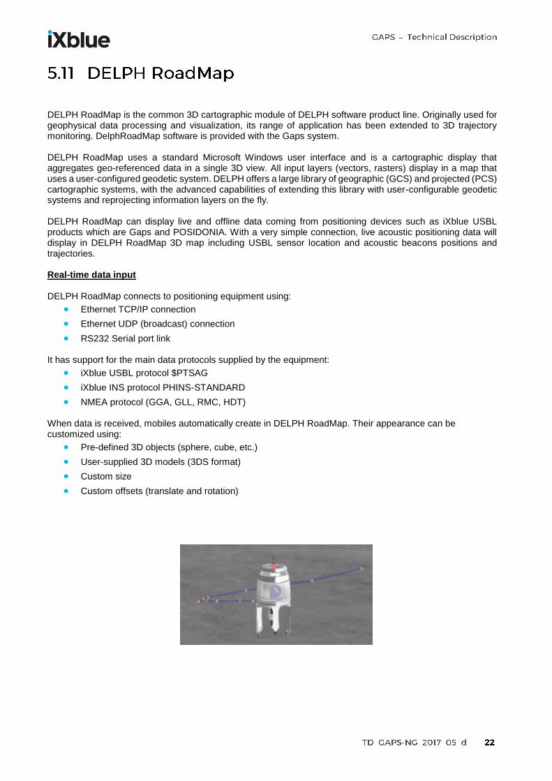
DELPH RoadMap is the common 3D cartographic module of DELPH software product line. Originally used for geophysical data processing and visualization, its range of application has been extended to 3D trajectory monitoring. DelphRoadMap software is provided with the Gaps system. DELPH RoadMap uses a standard Microsoft Windows user interface and is a cartographic display that aggregates geo-referenced data in a single 3D view. All input layers (vectors, rasters) display in a map that uses a user-configured geodetic system. DELPH offers a large library of geographic (GCS) and projected (PCS) cartographic systems, with the advanced capabilities of extending this library with user-configurable geodetic systems and reprojecting information layers on the fly. DELPH RoadMap can display live and offline data coming from positioning devices such as iXblue USBL products which are Gaps and POSIDONIA. With a very simple connection, live acoustic positioning data will display in DELPH RoadMap 3D map including USBL sensor location and acoustic beacons positions and trajectories. Real-time data input DELPH RoadMap connects to positioning equipment using:
Ethernet TCP/IP connection
Ethernet UDP (broadcast) connection
RS232 Serial port link It has support for the main data protocols supplied by the equipment:
iXblue USBL protocol $PTSAG
iXblue INS protocol PHINS-STANDARD
NMEA protocol (GGA, GLL, RMC, HDT) When data is received, mobiles automatically create in DELPH RoadMap. Their appearance can be customized using:
Pre-defined 3D objects (sphere, cube, etc.)
User-supplied 3D models (3DS format)
Custom size
Custom offsets (translate and rotation)

Offline data input Previously recorded data can be opened in DELPH RoadMap by inserting data records from supported protocols into the project. Replay data input Previously recorded data can be opened in DELPH RoadMap by inserting data records from supported protocols into the project. Display DELPH RoadMap cartographic view may be using different camera modes:
3D visualization
2D visualization
Relative positioning

Real-time measurement Users can easily choose couple of items for which they want to display measurement information in side panel and / or in the 3D view:
Horizontal Distance: On the map projection or ellipsoid
Vertical Distance
Slant Distance
Horizontal Bearing: On the map projection or ellipsoid
Vertical Angle

Gaps system provides data telegrams with each transponder’s position for use with any third party navigation package, with various communication protocols. Up to 8 Serial or Ethernet output are available which allow data distribution to different peripherals. Industry standard data telegrams are provided to easily interface each sensor to standard navigation packages from the market place such as Winfrog, Quinsy, etc.
GATOR QINSY NAVIPAC HYDROPRO HYPACK STARFIX
WINFROG DELPHROADMAP
GECDIS

Gaps can be interfaced to a subsea INS. The subsea INS receives the USBL position of the beacon (through the umbilical or using acoustic communication) and the INS make the fusion of all available internal or external) sensors (accelerometers, gyroscopes, pressure sensor, DVL, USBL) to deliver an optimized position of the ROV. This architecture brings the following advantages:
Position of the ROV is updated every 10 ms (whatever the acoustic update rate)
Position of the ROV is updated even when Gaps does not detect the beacon
The subsea INS rejects the erroneous USBL positions
The subsea INS filters/smooth the USBL positions The INS improves by a factor higher than 3 the positioning accuracy of the USBL if used alone.

The system integration requires different interfaces between surface and subsea equipment as shown on following diagram.

Transponders/Responders are the remote part of the Gaps positioning solution. They are installed on the subsea vehicle or target to position. Gaps is able to position iXblue and third party transponders. The list of compatible transponders is given below.
iXblue MT8x2 Mini beacon Lithium batteries
iXblue RTAx2 Releasable transponder
iXblue MT9x2 Mini beacon Rechargeable battery
iXblue RAMSES Synthetic LBL positioning system
iXblue ZTAx2C Beacon for seismic applications
Applied 1000 series (Micro, Mini, Midi, Fatboy, Seabed)
iXblue ET862 Expandable transponder
Sonardyne WidebandTM 1 modulation
iXblue MTB-OEM Beacon with telemetry for integration into AUVs
The positioning performance are not the same depending on the type of transponder. See dedicated paragraph.

Sub
-fam
ily
Mo
del
Dep
th (
m)
Load
Cap
acit
y in
T (
RL
/
SWL)
Ho
usi
ng
Size
(L
x O
D in
mm
)
Wei
ght
in k
g (a
ir /
wat
er)
Stan
d b
y (m
on
th)
Nb
of
Gap
s p
ings
Nb
of
add
ress
es
Du
al u
se
Co
nfi
gura
tio
n
Tele
met
ry (
ITS)
Exte
rnal
po
wer
su
pp
ly
Res
po
nd
er
Rem
ote
tra
nsd
uce
r
Lith
ium
bat
teri
es
Pre
ssu
re s
enso
r
Aco
ust
ic r
ele
ase
Exp
en
dab
le
OCEANO ET862S 6 000 N/A Super Duplex Stainless Steel
712 x 130 25.5 / 16 54 500 000 8 YES Internal switch
OCEANO ETA62S 6 000 N/A Super Duplex Stainless Steel
574 x 130 21 / 15 30 480 000 8 YES Serial link
Internal connector
Re
leas
able
OCEANO RTA62CS 6 000 0.5 / 2.5 Super Duplex Stainless Steel
625 x 126 24 / 17.5 30 480 000 8 YES Serial link
internal connector
OCEANO RTA62B2S 6 000 2.5 / 2.5 Super Duplex Stainless Steel
725 x 126 27 / 20.7 30 480 000 8 YES Serial link
internal connector
Min
iatu
re
MT832E-R 3 000 N/A Aluminium 500 x 70 2.8 / 1.2 4 50 000 8 YES Internal switch
MT862S-R 6 000 N/A Super Duplex Stainless Steel
490 x 70 5 / 3.5 4 50 000 8 YES Internal switch
MT912S-R 1 000 N/A 316L Stainless
Steel 377 x 91 4.4 / 2.3 5 100 000 40 NO
USB
External connector
MT932S-R 3 000 N/A 316L Stainless
Steel 368 x 91 5.7 / 3.8 5 100 000 40 YES
USB
External connector
ZTA02C 500 N/A Composite 396 x 98 3.9 / 1.4 16 500 000 506 NO Wireless, Zigbee®
ZTA32C 3000 N/A Composite 416 x 105 5.5 / 2.3 16 250 000 506 YES Wireless, Zigbee®
OEM MTB series OEM 1000 4000
N/A TBD TBD TBD TBD TBD 506 YES
(4000) Wireless
standard optional

Examples below demonstrate the extreme ease of operation of the system which does not require sophisticated mechanical pole or deployment machine to operate it.
This kind of installation is the most commonly used. A pole is installed on the side of the vessel and can be rotated in 2 positions: one position for the survey (side pole is vertical) and one position for the transit (side pole is horizontal).

For vessels equipped with moon pools, Gaps can be very easily deployed with a pole and a lifting system to recover the equipment.
The iXblue hoisting system is a robust and reliable hydraulically operated pole which is designed for the deployment of iXBlue USBL head (Gaps and POSIDONIA) below the vessel hull for permanent installations. The service chest with inspection door allows to access the equipment without dry-docking the vessel. The whole system is to be installed on the flange of a through hull penetration pipe.

Gaps can also be installed in existing hoisting system when gate valve is diameter is greater than 300 mm (external diameter is only 296 mm, i.e. 11.7 inch). Some examples below:
This deployment method is sometime used to drive away the Gaps head. This reduces the noise received by the USBL head and this improves the performances (maximum range and positioning accuracy).

Thanks to the INS inside the USBL transceiver, very light platforms such as simple buoys + pole can be used for some applications.
Because of its dimensions and its weight, Gaps is easy to integrate onto Unmanned Surface Vessels. No surface electronic rack is required, all the processing is done into the transceiver. The INS can be used for the navigation of the drone.

Interfacing is done from the rear panel of the Gaps BOX:
INTERFACING
Power supply / consumption 100 to 240 VAC - 50~60Hz or 24 to 36 VDC / 35 W (45 W peak)
Connector for VDC SOURIAU 4-pins - UTO00104PH
Main connector to Gaps head SOURIAU 23-pins - UT061823PH
Ethernet communication port 1 x RJ45 plug
Serial communication port 4 x DB9 connectors for RS232 or RS422/485 serial links
Synchronization IN & PPS 2 x BNC connectors (trigger and PPS)
Synchronization out 2 x BNC connectors (main and secondary)

The Repeater Box is necessary when two main cables (95 + 95 m or 95 + 50 m) are used simultaneously between the Gaps BOX and the Gaps unit. The Repeater Box realizes the junction between the two cables. Standard main cables are used so the connectors on the Repeater Box are similar to connectors on the Gaps BOX and on the Gaps antenna.
SPECIFICATION
Dimension (L x l x h) 217 x 188 x 68.5 mm
Weight 2.15 kg
Operating temperature(1) -5°C to +50°C
Temperature, storage(1) -20 °C to +80 °C
IP rating IP65
(1) NF X10-812

POSITIONING ACCURACY(2) CEP50 CEP90
SNR(3) = 0 dB 0.53% x slant range 1.06% x slant range
SNR(3) = 10 dB 0.17% x slant range 0.34% x slant range
SNR(3) = 20 dB 0.06% x slant range 0.12% x slant range
(2) In vertical conditions. With MT9x2 beacon. Transmit level = 191 dB ref µPa @ 1 m, sound velocity compensated, slant range of 1000 m
(3) SNR is input signal to noise ratio
RANGE/BEARING ACCURACY(4) RMS/STD DEV/1 sigma (68%) 2 sigma (95%)
SNR = 0 dB 0.02 m / 0.30° 0.04 m / 0.60°
SNR = 10 dB 0.02 m / 0.09° 0.04 m / 0.18°
SNR = 20 dB 0.02 m / 0.03° 0.04 m / 0.06°
(4) In vertical conditions. Responder mode.
PERFORMANCE
Range(5) 4 000 m
Coverage 200 deg below acoustic array
Operating frequency 21.7 – 30.3 kHz wideband
Position refresh rate 1 to 15 s (depends on range) – 10 Hz with predictive filter 1 s when ping stacking activated (whatever the range)
Nb of channels 8 with MT8 beacons 40 with MT9 beacons 529 with MTA beacons
Acoustic transmit level 191 dB ±3 dB ref. 1 µPa @ 1 m
(5) For a surface noise level below 67 dB ref µPa. Transponder transmit level = 191 dB ref. 1 µPa @ 1 m. Vertical conditions. With MT9x2 beacons.
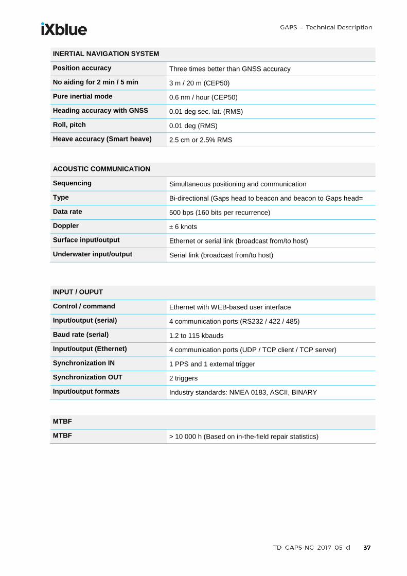
INERTIAL NAVIGATION SYSTEM
Position accuracy Three times better than GNSS accuracy
No aiding for 2 min / 5 min 3 m / 20 m (CEP50)
Pure inertial mode 0.6 nm / hour (CEP50)
Heading accuracy with GNSS 0.01 deg sec. lat. (RMS)
Roll, pitch 0.01 deg (RMS)
Heave accuracy (Smart heave) 2.5 cm or 2.5% RMS
ACOUSTIC COMMUNICATION
Sequencing Simultaneous positioning and communication
Type Bi-directional (Gaps head to beacon and beacon to Gaps head=
Data rate 500 bps (160 bits per recurrence)
Doppler ± 6 knots
Surface input/output Ethernet or serial link (broadcast from/to host)
Underwater input/output Serial link (broadcast from/to host)
INPUT / OUPUT
Control / command Ethernet with WEB-based user interface
Input/output (serial) 4 communication ports (RS232 / 422 / 485)
Baud rate (serial) 1.2 to 115 kbauds
Input/output (Ethernet) 4 communication ports (UDP / TCP client / TCP server)
Synchronization IN 1 PPS and 1 external trigger
Synchronization OUT 2 triggers
Input/output formats Industry standards: NMEA 0183, ASCII, BINARY
MTBF
MTBF > 10 000 h (Based on in-the-field repair statistics)
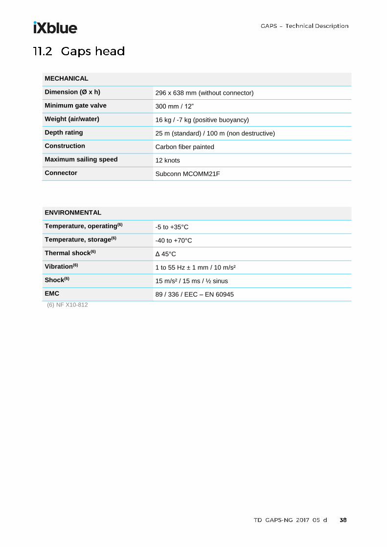
MECHANICAL
Dimension (Ø x h) 296 x 638 mm (without connector)
Minimum gate valve 300 mm / 12”
Weight (air/water) 16 kg / -7 kg (positive buoyancy)
Depth rating 25 m (standard) / 100 m (non destructive)
Construction Carbon fiber painted
Maximum sailing speed 12 knots
Connector Subconn MCOMM21F
ENVIRONMENTAL
Temperature, operating(6) -5 to +35°C
Temperature, storage(6) -40 to +70°C
Thermal shock(6) Δ 45°C
Vibration(6) 1 to 55 Hz ± 1 mm / 10 m/s²
Shock(6) 15 m/s² / 15 ms / ½ sinus
EMC 89 / 336 / EEC – EN 60945
(6) NF X10-812

MECHANICAL
Dimension (L x l x h) 361 mm x 233 mm x 93.5 mm
Weight 4.6 Kg
IP rating IP51
ENVIRONMENTAL
Temperature, operating(7) -5 to +50°C
Temperature, storage(7) -40 to +80°C
Humidity(7) 95% at 40°C
Vibration(7) 1 to 55 Hz ± 1 mm / 10 m/s²
Shock(6) 15 m/s² / 15 ms / ½ sinus
EMC EN 60950 / EN 61000
(7) NF X10-812

CABLE BETWEEN GAPS HEAD AND GAPS BOX
Length 50 m ± 1.5 m (option for 95 m ± 3 m and for repeater box when greater ranges are required)
ATEX Yes (option)
Diameter 15 mm (±0.8 mm) – 42 mm for the Subconn connector
Minimum bending radius 75 mm
Maximum pulling strength 150 daN
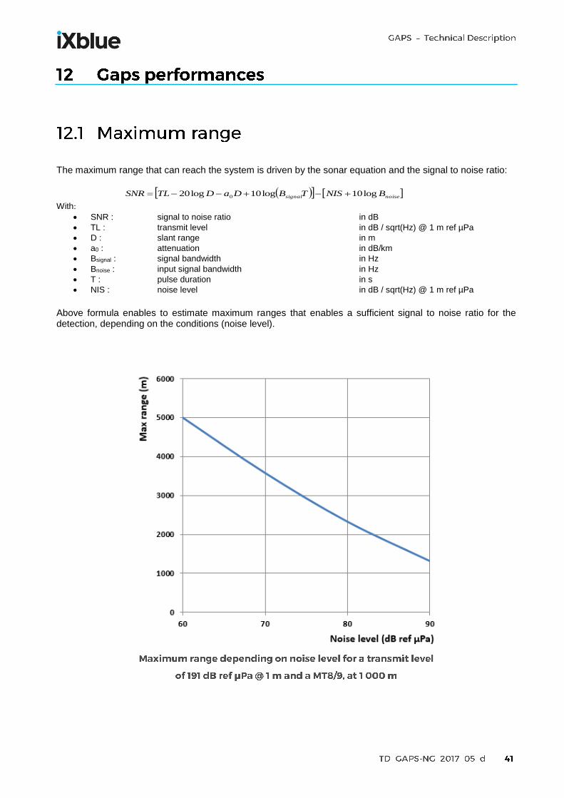
The maximum range that can reach the system is driven by the sonar equation and the signal to noise ratio:
noisesignal BNISTBDaDTLSNR log10log10log20 0
With:
SNR : signal to noise ratio in dB
TL : transmit level in dB / sqrt(Hz) @ 1 m ref µPa
D : slant range in m
a0 : attenuation in dB/km
Bsignal : signal bandwidth in Hz
Bnoise : input signal bandwidth in Hz
T : pulse duration in s
NIS : noise level in dB / sqrt(Hz) @ 1 m ref µPa
Above formula enables to estimate maximum ranges that enables a sufficient signal to noise ratio for the detection, depending on the conditions (noise level).

For the acoustic part of the global budget of error, the bearing accuracy is given by the Woodard formula (accuracy on bearing for a goniometer).
SNRp *2.sin.
With:
: wavelength in m
p
: distance between hydrophones in m
: target angle in rad
SNR: signal to noise ratio 10^(value in dB / 10)
Following graphic provides bearing accuracy for a beacon in responder mode, at 1000 m of slant range, in vertical conditions, for different noise levels.
Unlike other conventional USBL system the performance is inclusive of all sources of error such as GNSS (DGNSS mode), motion and heading internal sensors. The global budget of error is the quadratic sum of each error that are supposed to be independent. Following graphic provides positioning accuracy for a MT8/9 beacon in responder mode, in vertical conditions, for different SNR_in. It includes a GNSS error of 10 cm.

Below table and graphic present exact maximum ranges figures for the different models of compatible beacons.
(1) Transmit level is high setting (2) iXblue reply code (3) Requires Sonardyne WidebandTM 1 option, Beacons in responder mode
Noise level (dB ref µPa)
MT832 and MT932(1)
ZTA02C AAE 1219A and 1319A(2)
AAE 1019 (2) AAE 1065 (2) Sonardyne WidebandTM1 192 dB ref 1 µPa @ 1 m(3)
60 5000 m 1500 m 3450 m 4135 m 6380 m 4520 m
70 3580 m 1500 m 2220 m 2800 m 4850 m 3150 m
80 2330 m 1500 m 1230 m 1690 m 3450 m 1965 m
90 1320 m 1000 m 570 m 860 m 2215 m 1050 m

Following table provides positioning accuracy for a beacon in responder mode, at 1000 m of slant range, in vertical conditions, for different noise levels and a GNSS with a 10 cm accuracy.
Noise level (dB ref µPa)
MT832 and MT932(1)
ZTA02C AAE 1219A and 1319A
(2)
AAE 1019 (2) AAE 1065 (2)
Sonardyne WidebandTM1 192 dB ref 1 µPa @ 1 m
(3)
60 0.33 m 0.46 m 0.96 m 0.56 m 0.22 m 0.44 m
70 0.86 m 1.34 m 2.97 m 1.68 m 0.36 m 1.24 m
80 2.65 m 4.19 m 9.38 m 5.28 m 0.96 m 3.87 m
90 8.36 m 13.25 m No detec. No detec. 2.97 m 12.21
(1) Transmit level is high setting (2) iXblue reply code (3) Requires Sonardyne WidebandTM 1 option, CEP50

Unless Gaps acoustic antenna is designed to have excellent performances in horizontal tracking and due to acoustic propagation, the performances for high elevation angles is less than in vertical conditions. The positioning accuracy, depending on vertical angle can be estimated as below:
Vertical angle MT832 and MT932(1)
0 deg 0.06 % of the S.R.
30 deg 0.06 % of the S.R.
60 deg 0.10 % of the S.R.
90 deg 0.30 % of the S.R.
(1) SNR_in = 20 dB ref µPa, CEP50
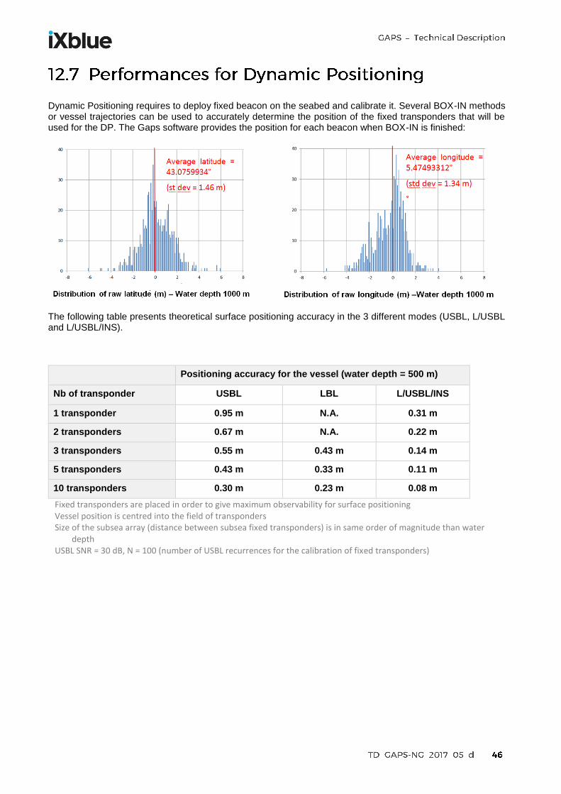
Dynamic Positioning requires to deploy fixed beacon on the seabed and calibrate it. Several BOX-IN methods or vessel trajectories can be used to accurately determine the position of the fixed transponders that will be used for the DP. The Gaps software provides the position for each beacon when BOX-IN is finished:
The following table presents theoretical surface positioning accuracy in the 3 different modes (USBL, L/USBL and L/USBL/INS).
Positioning accuracy for the vessel (water depth = 500 m)
Nb of transponder USBL LBL L/USBL/INS
1 transponder 0.95 m N.A. 0.31 m
2 transponders 0.67 m N.A. 0.22 m
3 transponders 0.55 m 0.43 m 0.14 m
5 transponders 0.43 m 0.33 m 0.11 m
10 transponders 0.30 m 0.23 m 0.08 m
Fixed transponders are placed in order to give maximum observability for surface positioning Vessel position is centred into the field of transponders Size of the subsea array (distance between subsea fixed transponders) is in same order of magnitude than water
depth USBL SNR = 30 dB, N = 100 (number of USBL recurrences for the calibration of fixed transponders)

Conditions
Location: La Ciotat Bay, South of France
Data logged into January 2016
Water depth is 46 m
Two beacons are clamped onto a rope and are deployed above the seabed with buoyancy (beacons are not supposed to move)
Gaps is deployed from a surface vessel equipped with RTK GNSS (0.1 m accuracy)
Vessel is drifting with the wind and the current above the beacon
The horizontal distance is varying from 0 to 20 m
Logging duration: 5 mn
Positioning recurrence: 2 s (150 USBL fix per beacon)
Beacon model: ZTA02C
Gaps model: Gaps IV
Sound velocity measured and configured into the Gaps
No pressure sensor on the beacon

Lat/Long graph
Lat/Long graph versus time
Beacon ID 1 Beacon ID 2
Latitude std dev 0.11 m 0.09 m
Longitude std dev 0.12 m 0.08 m
Depth std dev 0.03 m 0.03 m
CEP-50 0.10 m 0.07 m

Conditions
Location: La Ciotat Bay, South of France
Data logged into March 2012
Water depth is 50 m
A beacon is clamped onto a rope and are deployed above the seabed with buoyancy (beacons is not supposed to move)
Gaps is deployed from a surface vessel equipped with RTK GNSS (0.1 m accuracy)
Vessel is sailing around the beacons and horizontal distance is increased
Gaps model: Gaps III
Sound velocity measured and configured into the Gaps
No pressure sensor on the beacon
Noise level: 86 dB ref µPa
Average SNR_in: 10 dB
Horizontal range / vertical angle Positioning accuracy
(in m) CEP 50
Positioning accuracy (in % of the S.R.)
CEP 50
50 m / 45 deg 0.11 m 0.16%
100 m / 63 deg 0.22 m 0.20%
150 m / 72 deg 0.36 m 0.23%
200 m / 76 deg 0.56 m 0.27%
250 m / 79 deg 0.62 m 0.24%
300 m / 80 deg 0.67 m 0.22%

During storage and transportation, Gaps and its accessories should be kept locked in its transportation case. The whole system is packed in two reusable transit cases for the Gaps and its accessories and a plywood transit case for the transponder only: Important note: Gaps is a dual use product that require authorization if leaving European Community.
Because the INS and the acoustic parts are built in the same housing, there is no need to recalibrate the system periodically. The calibration is only required following hydrophones/legs replacement, when user needs nominal positioning accuracy.
Gaps includes a Continuous Built-In Test (CBIT) that covers internal sensor status verification, system status and algorithm status. The User Manual document details the complete list of parameters that are monitored.
Subconn recommends a replacement of the 24-pins connector every 4 years to avoid any water ingress. But thanks to the technology used in its design, Gaps does not require any kind of preventive maintenance except regular visual inspections for permanent installations, under vessel hulls to check for marine growth.

Hydrophones and short/long legs can be ordered separately as spare parts and replaced on the field.
A new hydrophone design to protect Gaps mechanical structure in case of an incident:
One connector only
Longer cable providing more freedom to the damaged part
One single design for all hydrophones
Breakable sections in the lead cable to protect connector in case of traction or flexion
To reach nominal performances after a hydrophone/leg replacement, a calibration must be performed. This requires to deploy a fixed beacon on the seabed (100 m to 1000 m of water depth), sail around the beacon and use a dedicated calibration software which is provided with the system.

The main customers are rental companies, offshore companies, military and scientific institutes.
ALDA MARINE (France)
Submarine cable deployment
ASHTEAD (UK)
Rental company
Belgian Navy (Belgium)
Mine Counter Measure Vehicle : Double Eagle
BOSKALIS (Netherlands)
Dredging, construction, survey
C&C Technology (USA)
Survey. Vehicle: C-Surveyor I
COSL (China)
Survey
COMRA (China)
Oceanographic Institute ROV and AUV positioning Dynamic Positioning
DE BEERS (South Africa)
Subsea mining Drill head positioning
FUGRO (Netherlands)
Survey. Vehicle: Echo Surveyor II
IFREMER (France)
ROV and AUV positioning Dynamic Positioning
ISE (Canada)
AUV tracking

JOGMEC (Japan)
Drilling, mining, ROV positioning
MARUM (Germany) Research University ROV tracking
MMTAB (Sweden)
Multibeam survey with tow fish
NIOT (India)
Oceanographic Institute
P&O Maritime (Ireland)
ROV positioning and Dynamic Positioning
Petrobras / Cybernetix (Brazil)
Buoyancy supported riser (BSR) monitoring system
SAIPEM (France)
Pipe laying and subsea construction
SBGS (USA / Norway)
Ocean Bottom Cable
Seatronics (UK)
Rental company
ST Electronics (Singapore)
Mine sweeping
STR (UK)
Rental company
Unique Systems (USA)
Rental company
Van Oord (Netherdlands)
Multi purpose vessels to install cables for wind farm

