applied p hysics l aboratory -...
TRANSCRIPT

FSCM NO. SIZE DRAWING NO. REV.
SCALE DO NOT SCALE PRINT SHEET
THE JOHNS HOPKINS UNIVERSITY
APPLIED PHYSICS LABORATORY11100 JOHNS HOPKINS ROAD, LAUREL, MARYLAND 20723-6099
88898
XXXX
A 7417-9100 - 1 of 36
Revision: -
Date: June 11, 2012
Radiation Belt Storm Probes (RBSP)
Space Weather Interface Control Document
07/23/2012 11:37 Rev - UNCONTROLLED OUTSIDE OF PLM

FSCM NO. SIZE DRAWING NO. REV.
SCALE DO NOT SCALE PRINT SHEET
88898 A 7417-9100 -
2 of 36
Technical Content Approval
Prepared/Approved by:
Nicola J. Fox
RBSP Deputy Project Scientist
Michele B. Weiss
RBSP Space Weather Lead
Approved by:
Richard J. Fitzgerald Barry H. Mauk
RBSP Project Manager RBSP Project Scientist
James M. Stratton Debbie A. Clancy
RBSP Mission Systems Engineer RBSP Software Systems Engineer
Kim A. Cooper David A. Artis
RBSP Deputy Project Manager, Instrument RBSP Data Systems Engineer
Raymond J. Harvey W. Mark Reid
RBSP Ground Segment Systems Engineer RBSP Flight Software Lead
Dipak K. Srinivasan Richard J. Pfisterer
RBSP RF Telecommunications Lead RBSP System Assurance Manager
07/23/2012 11:37 Rev - UNCONTROLLED OUTSIDE OF PLM
FSCM NO. SIZE DRAWING NO. REV.
SCALE DO NOT SCALE PRINT SHEET
88898 A 7417-9100 -
3 of 36
Technical Content Approval (continued)
The following personnel have reviewed/approved by display of e-mail response/signature for this
release as cited below:
Harlan Spence
ECT PI
Craig Kletzing
EMFISIS PI
David Byers
PSBR PI
John Wygant
EFW PI
07/23/2012 11:37 Rev - UNCONTROLLED OUTSIDE OF PLM

FSCM NO. SIZE DRAWING NO. REV.
SCALE DO NOT SCALE PRINT SHEET
88898 A 7417-9100 -
4 of 36
Technical Content Approval (continued)
The following personnel have reviewed/approved by display of e-mail response/signature for this
release as cited below:
Louis Lanzerotti
RBSPICE PI
Keith Goetz
EFW Project Manager
A Release stamp electronically affixed at bottom of the pages of this document certifies that the
above personnel or designated alternates have approved this initial release. Please refer to the
APL Product Lifecycle Management System (PLM) for record of these approvals.
07/23/2012 11:37 Rev - UNCONTROLLED OUTSIDE OF PLM

FSCM NO. SIZE DRAWING NO. REV.
SCALE DO NOT SCALE PRINT SHEET
88898 A 7417-9100 -
5 of 36
Revision Log
Revision Date Author Description of Change
Draft 10/09/2009 Nicola J. Fox Draft
Draft a 12/28/2011 Michele B. Weiss Updated RBSPICE telemetry packets with
actual energies. Added ECT/MagEIS
Med35 packet. Updated ECT/HOPE
packet definitions.
Draft b 2/1/2012 Michele B. Weiss Clarification that the ECT/MagEIS
medium 35 or 75 instrument can generate
space weather data.
Draft c 2/14/12 Michele B. Weiss Update EMFISIS packet definitions.
Draft d- 2/15/12 Michele B. Weiss Updated when the Ephemeris Prediction is
available
- Michele B. Weiss Original Release
Michele B. Weiss Added references to the CCSDS Blue
Books, updated acronyms
- 4/24/12 Michele B. Weiss Updated EMFISIS data rate
- 6/11/12 Michele B. Weiss Initial Release
07/23/2012 11:37 Rev - UNCONTROLLED OUTSIDE OF PLM

FSCM NO. SIZE DRAWING NO. REV.
SCALE DO NOT SCALE PRINT SHEET
88898 A 7417-9100 -
6 of 36
TABLE OF CONTENTS
1 INTRODUCTION .......................................................................................... 8
1.1 Purpose...................................................................................................................... 8
1.2 Scope.......................................................................................................................... 8
1.3 Configuration Management .................................................................................... 8
1.4 Applicable Documents ............................................................................................. 8
1.5 References ................................................................................................................. 9
2 RBSP PROJECT OVERVIEW ................................................................... 10
2.1 Payload and Mission .............................................................................................. 10
3 SPACE WEATHER BROADCAST DATA ................................................. 13
3.1 Approach ................................................................................................................ 13
3.2 Space Weather Data Set ........................................................................................ 14
4 IMPLEMENTATION AND LIMITATIONS OF THE SPACE WEATHER BROADCAST............................................................................................. 16
5 RECEIVING THE SPACE WEATHER BROADCAST DATA .................... 20
6 DOWNLINK AND TELEMETRY FORMATS .............................................. 21
6.1 Telemetry Transfer Frame.................................................................................... 21
6.2 Telemetry Frame Definition .................................................................................. 21
6.3 Frame Virtual Channel ......................................................................................... 22
6.4 Frame Secondary Header...................................................................................... 22
7 SPACE WEATHER PACKET DEFINITIONS ............................................. 23
7.1 EMFISIS Space Weather Data ............................................................................. 23
7.2 EFW Space Weather Data .................................................................................... 24
7.3 ECT/HOPE Space Weather Data ......................................................................... 24
7.4 ECT/MagEIS Space Weather Data ...................................................................... 27
7.5 ECT/REPT Space Weather Data ......................................................................... 28
07/23/2012 11:37 Rev - UNCONTROLLED OUTSIDE OF PLM

FSCM NO. SIZE DRAWING NO. REV.
SCALE DO NOT SCALE PRINT SHEET
88898 A 7417-9100 -
7 of 36
7.6 RBSPICE Space Weather Data ............................................................................ 29
7.7 PSBR/RPS Space Weather Data........................................................................... 30
8 PREDICTED EPHEMERIS FILES .............................................................. 31
9 SPACE ASSET PROTECTION POLICY IMPLICATIONS ......................... 32
10 INSTITUTIONAL RESPONSIBILITIES ...................................................... 33
10.1 Radiation Belt Storm Probes Mission .................................................................. 33
10.2 NASA Program Office ........................................................................................... 33
10.3 Ground Station Partners ....................................................................................... 33
11 COMMUNICATION BETWEEN RBSP AND THE PARTICIPATING GROUND STATIONS ................................................................................ 34
APPENDIX A: ACRONYMS ......................................................................................... 35
07/23/2012 11:37 Rev - UNCONTROLLED OUTSIDE OF PLM
FSCM NO. SIZE DRAWING NO. REV.
SCALE DO NOT SCALE PRINT SHEET
88898 A 7417-9100 -
8 of 36
1 INTRODUCTION
1.1 PURPOSE
The Radiation Belt Storm Probe (RBSP) Space Weather ICD presents a high-level strategy for
the generation and broadcasting of real-time space weather data from the RBSP instruments. The
space weather data to be broadcast from RBSP comprises a small fraction of the scientific data
obtained by the instruments. The broadcasts are intended to be received by ground stations
supplied, operated, and funded by interested parties external to the RBSP Program and Project.
1.2 SCOPE
The ICD defines the data products from each RBSP instrument, data products to be supplied by
the Mission Operations Center (MOC), and the necessary information needed by a ground station
for the capturing the broadcasted data.
Specific aspects addressed in this ICD are:
1. Space weather broadcast data
2. Implementation and limitations of the space weather broadcast
3. Information on how to receive the space weather data
4. Downlink and telemetry formats
5. Data packet definitions
6. Space asset protection policy implications
7. Institutional responsibilities
1.3 CONFIGURATION MANAGEMENT
The data contained in this document represents the current definition of the Radiation Belt Storm
Probe Mission Space Weather Interface Control Document. This document, after formal release,
shall be revised only through the formal change control procedures as described in the RBSP
Configuration Management Plan.
1.4 APPLICABLE DOCUMENTS
Level 1 Requirements for the Radiation Belt Storm Probes Mission
7417-9013 RBSP Mission Requirements Document (MRD)
7417-9148 RBSP Science Team Allocated Requirements Document (STARD)
7417-9016 RBSP Concept of Operations
7417-9050 RBSP Mission Operations Center (MOC) to RBSP Science Operations Center
(SOC) and Interface Control Document (ICD)
7417-9129 RBSP Science Data Management Plan (SDMP)
07/23/2012 11:37 Rev - UNCONTROLLED OUTSIDE OF PLM

FSCM NO. SIZE DRAWING NO. REV.
SCALE DO NOT SCALE PRINT SHEET
88898 A 7417-9100 -
9 of 36
7417-9105 RBSP Mission Operations Center (MOC) Data Products Document
7417-9097 RBSP Spacecraft to Satellite Communications Facility (SCF) to Mission
Operations Center (MOC) Interface Control Document (ICD)
7417-9609 RBSP Ground Software to Flight Software Interface Control Document
1.5 REFERENCES
1. CCSDS 133.0-B-1 Space Packet Protocol. Blue Book. Issue 1. September 2003.
2. CCSDS 132.0-B-1 TM Space Data Link Protocol. Blue Book. Issue 1. September 2003.
07/23/2012 11:37 Rev - UNCONTROLLED OUTSIDE OF PLM

FSCM NO. SIZE DRAWING NO. REV.
SCALE DO NOT SCALE PRINT SHEET
88898 A 7417-9100 -
10 of 36
2 RBSP PROJECT OVERVIEW
2.1 PAYLOAD AND MISSION
The RBSP mission targets Earth’s radiation belts of magnetically trapped, very high energy
electrons and ions. Its scientific objective is to understand, ideally to the point of predictability,
how populations of high energy relativistic electrons and penetrating ions in space are produced
and change in response to the variable inputs of energy from the Sun. The mission comprises 2
near-sun oriented observatories, which are spin stabilized ~5 rpm with a spin-axis oriented 16°-
20° from the Earth-Sun line, and that reside in nearly identical, highly elliptical, near equatorial
orbits with apogees just below 6 Earth radii geocentric (Figure 1). The observatories have an
operational design life of 2 years. The understanding gained by RBSP will enable us, in the
future, to better protect space assets in near-Earth environment. In addition to the scientific data
returned to achieve this understanding, the RBSP mission provides a 1 kbps space weather
broadcast in support of real time space weather modeling, forecast and prediction efforts.
Figure 1. Orbit configuration of the RBSP spacecraft
The unusual orbit of the RBSP spacecraft will provide great insight into many regions of the
radiation belts. The highly elliptical orbit of RBSP will provide data from the non-traditional
Perigee Altitude 625 km
Observatory 1 Apogee
Altitude 30,615 km Observatory 2 Apogee
Altitude 30,470 km
Differing apogees allow for simultaneous measurements to be taken over the full range of observatory separation distances several times over the course of the mission. This design allows
Observatory 2 to lap Observatory 1 every 79 days.
Inclination 10°
07/23/2012 11:37 Rev - UNCONTROLLED OUTSIDE OF PLM
FSCM NO. SIZE DRAWING NO. REV.
SCALE DO NOT SCALE PRINT SHEET
88898 A 7417-9100 -
11 of 36
orbital locations - operational monitoring satellites are usually at or near geosynchronous orbit.
For 3-D specification models, these altitude-varying profiles will provide greater sampling of
Earth’s radiation environment
It has always been an important objective that the space weather broadcasts not become a cost
driver on the mission. Thus, there is no dedicated space weather beacon or transmitter aboard the
spacecraft, but rather the space weather data will be broadcast in real-time through the primary
spacecraft RF system, used for the science downlink. The observatory will broadcast space
weather when it is not in a primary mission-related ground contact. The data will be received by
users that maintain and fund their own ground station antennas. NASA headquarters is
responsible for the identification of users and for programmatic interfaces between the users and
the RBSP Project.
It is desirable that as much of the Space Weather Broadcast data be captured in real-time as
possible. Because of the geometry of the mission configuration of spacecraft orientations and
orbits, the RBSP mission presents challenges for generating broadcasts that can be received
continuously by ground stations, in the fashion of the ACE and STEREO missions. The data
capture is limited by the availability of space weather ground stations and the poor downlink
geometry for portions of the mission. Additionally, the real time coverage will be reduced by an
average of 2.5 hours for each observatory per day due to primary mission contacts. Often one of
the two observatories will still be available because many contacts with each observatory do not
overlap.
Each of the RBSP payload instruments will be participating in the real-time space weather
broadcast. The RBSP payload includes the following science investigations:
1. The Energetic Particle, Composition and Thermal Plasma Suite (ECT). This investigation
will determine the spatial, temporal, and pitch angle distributions of electrons and ions over a
broad and continuous range of energies, from a few eV to > 10 MeV for electrons, and from a
few eV to many 10’s of MeV for ions. It is designed to differentiate the causes of particle
acceleration mechanisms, understand the production of plasma waves, determine how the inner
magnetospheric plasma environment controls particle acceleration and loss, and characterize
source particle populations and their transport. The investigation will provide a complete
complement of data analysis techniques, case studies, theory, and modeling, along with expertise
to define particle acceleration mechanisms, radiation belt particle enhancement and loss, and
determine how the near-Earth environment controls those acceleration and loss processes.
2. The Electric and Magnetic Field Instrument Suite and Integrated Science (EMFISIS). This
investigation will provide the observations needed to determine the origin of important plasma
wave classes and their role in particle acceleration and loss processes. The investigation will
also quantify the evolution of the magnetic field that defines the basic coordinate system
controlling the structure of the radiation belts and the storm-time ring current. EMFISIS will
provide calculations of on board spectra, including spectral matrices, making it possible to
determine wave normal angles and Poynting fluxes for the plasma waves of interest and
providing information for wave mode identification and propagation modeling which are
07/23/2012 11:37 Rev - UNCONTROLLED OUTSIDE OF PLM

FSCM NO. SIZE DRAWING NO. REV.
SCALE DO NOT SCALE PRINT SHEET
88898 A 7417-9100 -
12 of 36
essential for understanding and modeling of radiation particle physics. EMFISIS will also
measure the upper hybrid frequency, permitting accurate determination of the electron plasma
density required for analysis of wave propagation and instability growth rates.
3. Electric Field and Waves (EFW) Instrument. The investigation will provide the
observations needed to understand the electric field properties associated with particle
energization, scattering and transport, and the role of the large-scale convection electric field in
modifying the structure of the inner magnetosphere. EFW measurements of the spacecraft
potential will be used to infer the ambient plasma density.
4. Radiation Belt Storm Probes Ion Composition Experiment (RBSPICE). This investigation
will provide observations that accurately resolve the ring current pressure distribution needed to
understand how the inner magnetosphere changes during geomagnetic storms and how that storm
environment supplies and supports the acceleration and loss processes involved in creating and
sustaining hazardous radiation particle populations.
5. The Proton Spectrometer Belt Research (PSBR). This investigation will determine the
upper range of proton fluxes, up to ~2 GeV, in the inner magnetosphere and develop and validate
models of the Van Allen radiation belts.
07/23/2012 11:37 Rev - UNCONTROLLED OUTSIDE OF PLM
FSCM NO. SIZE DRAWING NO. REV.
SCALE DO NOT SCALE PRINT SHEET
88898 A 7417-9100 -
13 of 36
3 SPACE WEATHER BROADCAST DATA
3.1 APPROACH
The RBSP instrument suites will select space weather data to be broadcast from their collected
science data on board the observatories. The instruments will choose space weather data from
measurements based on information normally available to the instrument. The data subset
includes particle fluxes, at a variety of energies, and magnetic and electric field data as detailed
in the table below. The exact energy and frequency ranges are subject to review as the instrument
teams continue to refine their selection of data products.
The implementation for PSBR/RPS is different than for the other RBSP instruments. Their
housekeeping packet will be broadcast once every second and the space weather products are
embedded within this packet. The details of their housekeeping packet are in Section 7. Packet
size = 38 bytes @ 1 per second = 304 bps. The two space weather products are given in bytes 10,
12 and 34. Specifically these are PEN and CHE rates - 1-second coincidence rates as fluxes (>50
~MeV, and > ~400 MeV protons) – and the onboard dosimeter data which come in
as multiplexed voltages from a linear (quick rollover) and logarithmic (slow rollover) dose
accumulator. An algorithm for unpacking these data will be provided to the users by the PSBR
team.
In addition to the real-time products, it is a goal for a “quick look” product to be produced by
each of the individual instrument Science Operations Centers (SOC). These products will
essentially “fill in the gaps” caused by times when the broadcast data cannot be received and also
provide a more complete data set for use in the diagnostics of anomalies at LEO and MEO.
07/23/2012 11:37 Rev - UNCONTROLLED OUTSIDE OF PLM

FSCM NO. SIZE DRAWING NO. REV.
SCALE DO NOT SCALE PRINT SHEET
88898 A 7417-9100 -
14 of 36
3.2 SPACE WEATHER DATA SET
Table 1 shows the space weather data products that will be generated by the various sensors on
RBSP and included in the space weather broadcasts.
Table 1. RBSP Real Time Data Set Instrument Measurement Energy Cadence Data
Rate
(bps)
Space Weather APID
EMFISIS/
MAG
Vector
Magnetic Field
NA 1 vector/12 seconds 24 0x28C
EMFISIS/
Waves
VLF Wave
Power
NA Electric field
spectral density at 3
frequencies every 12
seconds; Magnetic
field spectral density
at 3 frequencies
every 12 seconds
EFW Vector Electric
Field
NA 1 vector/spin 18.66
0x26A
Spacecraft
Potential
NA Once/spin
ECT/HOPE Electrons 24.54 eV, 281
eV, 10.9 keV,
42.9 keV **
Once/24 seconds* 76 0x22C (ions)
0x22D (electrons)
Protons 24.54 eV, 281
eV, 10.9 keV,
42.9 keV
Once/24 seconds*
* Ions and electrons
are sampled
alternately every
other spin
Oxygen Ions 24.54 eV, 281
eV, 10.9 keV,
42.9 keV
Helium Ions 24.54 eV, 281
eV, 10.9 keV,
42.9 keV
ECT/ MagEIS Energetic
Electrons
30 keV 60 keV,
100 keV, 300
keV, 600 keV, 1
MeV, 2 MeV
Once/spin 105.6 0x34A (Low electrons)
0x36A (Med75
electrons)
0x375 (High electrons)
0x382 (High protons) Energetic
Protons
1 MeV
ECT/REPT Very Energetic
Electrons
2 MeV, 5 MeV,
10 MeV
Once/spin 14.4 0x201
Energetic
Protons
>20 MeV, >50
MeV, >70 MeV
RBSPICE Energetic
Protons
50 keV,
100 keV, 150
keV, 300 keV,
1 MeV, 10 MeV
Once/spin 136 0x311
07/23/2012 11:37 Rev - UNCONTROLLED OUTSIDE OF PLM

FSCM NO. SIZE DRAWING NO. REV.
SCALE DO NOT SCALE PRINT SHEET
88898 A 7417-9100 -
15 of 36
PSBR/RPS
Energetic
Protons
>50 MeV, >400
MeV
Once/1 seconds
304
0x2C1
Dosimeter
Data
Linear and Log
outputs (Volts)
** ECT/HOPE has 16 different energy sweep tables, with table 0 being the nominal sweep.
Picking data off for space weather is based solely on the step number within the in-use sweep
table, so when HOPE is not using the nominal table (table 0) the selected energies may not be 25,
300, 10k, and 40kev. The ESA sweep table that was in use when the space weather data was
generated is reported in the ESA_TABLE field included in each packet.
07/23/2012 11:37 Rev - UNCONTROLLED OUTSIDE OF PLM

FSCM NO. SIZE DRAWING NO. REV.
SCALE DO NOT SCALE PRINT SHEET
88898 A 7417-9100 -
16 of 36
4 IMPLEMENTATION AND LIMITATIONS OF THE SPACE WEATHER
BROADCAST
The RBSP mission observatories will communicate with the ground via S-Band using an 8W
Solid State Power Amplifier (SSPA) transmitters. The observatory pointing geometry, orbit, and
spin stabilization determines communication system requirements. Earth location, as viewed
from the spacecraft, covers a very broad angle space (mast angle) as shown in the required RBSP
antenna angle coverage plot below (Figure 2). Contact geometry necessitates onboard antennas
that have broad angular coverage and low gain.
Figure 2: Required RBSP Antenna Angle Coverage
The coverage is maximized within practical limits using two low gain antennas. The two RF
antennas’ boresights are aligned with the spacecraft spin- and anti-spin-axes, providing coverage
from their boresight to 70º. Despite maximizing the antenna coverage, there is still a 40° null
band, depicted in Figure 2 as the gray patch in the antenna angle coverage plot. Both antennas
are active at all times, as there is no active switching between antennas. Instead, a passive
splitter/combined sums the antenna patterns. The top antenna and bottom antenna generate
circularly polarized emissions with RBSP A using Right Hand Circular Polarization and RBSP B
using Left Hand Circular Polarization. The spacecraft and antenna patterns are illustrated in
Figure 3.
0 0.5 1 1.5 2 2.5 3 3.5 4 4.5
x 104
0
20
40
60
80
100
120
140
160
180
Range (km)
Mast
An
gle
(d
eg
)
Null Region
07/23/2012 11:37 Rev - UNCONTROLLED OUTSIDE OF PLM

FSCM NO. SIZE DRAWING NO. REV.
SCALE DO NOT SCALE PRINT SHEET
88898 A 7417-9100 -
17 of 36
Figure 3: RBSP RF Antenna Covereage
The antenna coverage to Earth depends on orbit geometry that seasonally varies as illustrated in
Figure 4 – a view of the orbit changes as seen from a vantage pointing looking down on the
Earth from the North Pole. Although antenna coverage is large, there are times when the antenna
patterns are not aligned with the Earth. The large eccentricity of the orbit causes larger periods of
time when antennas are not in view during certain times of the year because the relative angle
between the observatory and Earth changes slowly over long periods of time. Observatory orbits
are at a low inclination (10°) and the orbit harmonics cause the apogee and perigee to drift
between northern and southern hemispheres. Stations near the equator will have the best year-
around coverage while high latitude stations may have some limits in coverage over portions of
the orbit for parts of the year.
07/23/2012 11:37 Rev - UNCONTROLLED OUTSIDE OF PLM

FSCM NO. SIZE DRAWING NO. REV.
SCALE DO NOT SCALE PRINT SHEET
88898 A 7417-9100 -
18 of 36
For the potential ground reception of the space weather broadcast, the maximum observatory
contact duration as a function of the number of ground stations can be maximized by using
multiple stations with longitudinal diversity. The plot below (Figure 5) shows the coverage for 1,
2, 3 and 4 ground stations with maximum angular separation – i.e. 2 are separated by 180o; 3 by
120o; and 4 by 90
o. The peaks and valleys in potential contact periods are primarily due to
seasonal effects on observatory antenna coverage. Normal observatory contacts (i.e. downlinking
of science data and uplinking commands etc.) would reduce available time for space weather by
an average of 2.5 hours per observatory per day (~10% per observatory).
View from North Pole of Ecliptic Plane
Null
Lin
e o
f apsid
es
Earth
Figure 4: Degree of
antenna coverage due to
seasonal variations
07/23/2012 11:37 Rev - UNCONTROLLED OUTSIDE OF PLM

FSCM NO. SIZE DRAWING NO. REV.
SCALE DO NOT SCALE PRINT SHEET
88898 A 7417-9100 -
19 of 36
Figure 5: Average Contact Time per Day (%)
Min. Angle Between Earth-Sun Line & Line of Apsides (deg)
• Visibility averaged over 3 day increments
• Two 70° half angle antennas
• Generic ground stations assumed at 35° N latitude
Assumptions:
07/23/2012 11:37 Rev - UNCONTROLLED OUTSIDE OF PLM

FSCM NO. SIZE DRAWING NO. REV.
SCALE DO NOT SCALE PRINT SHEET
88898 A 7417-9100 -
20 of 36
5 RECEIVING THE SPACE WEATHER BROADCAST DATA
Each RBSP spacecraft provides a 1 kbps space weather broadcast–rate, 1/2 convolutionally
encoded, direct-on-carrier phase modulation, bi-phase data. The mission will use a modulation
index of 0.9 radians during space weather broadcast (Table 2). This choice enables a 5-m ground
station dish with a noise temperature of 390K to close out the space weather link when the
spacecraft are at apogee. Table 3 provides the broadcast carrier frequencies.
Table 2: Telemetry Mode for Space Weather
Bit Rate
(bps) Encoding
Symbol Rate
(ksps) Carrier Modulation
Data
Format
Network
1000 Conv. 1/2 2000 PM, 0.9 rad peak Biphase Space Weather
The RBSP Command and Data Handling (C&DH) subsystem will provide real-time space
weather packets in CCSDS telemetry packets downlinked as CCSDS frames. The frame format
is defined in Table 4. The space weather packets will be broadcast in real time when not in a
ground contact. The space weather data will not be recorded on the on-board Solid State
Recorder. Each RBSP instrument will provide their space weather data in separate CCSDS
telemetry packets (the same scenario that is used for the STEREO mission). Each packet has a
unique APID. RBSP Mission Operations controls when Space Weather is downlinked and what
packets are provided. Nominally, at the end of a ground contact, the C&DH subsystem is
configured to flow Space Weather data in real-time at the downlink configuration and rates
mentioned in this ICD.
Table 3. RF Downlink Parameters.
Parameter RBSP-A RBSP-B
Spacecraft ID 16A 16B
Downlink
Transmit frequency S-band S-band
07/23/2012 11:37 Rev - UNCONTROLLED OUTSIDE OF PLM

FSCM NO. SIZE DRAWING NO. REV.
SCALE DO NOT SCALE PRINT SHEET
88898 A 7417-9100 -
21 of 36
6 DOWNLINK AND TELEMETRY FORMATS
6.1 TELEMETRY TRANSFER FRAME
The transfer frame contains a primary header and secondary header followed by a frame data
field which consists of one or more telemetry packets. This structure is shown below in figure 6.
The frame ends with a 16-bit Frame Error Control Field and the 32-bit Command Link Control
Word (CLCW) for the virtual channel.
Telemetry packets contained within the transfer frame may be variable length. Thus telemetry
packets may span across transfer frames and the start of a new transfer frame will not ordinarily
be aligned with the start of a telemetry packet.
Figure 6: Telemetry Transfer Frame Format
6.2 TELEMETRY FRAME DEFINITION
Table 4 provides the contents of the Space Weather telementry frames and the CCSDS telemetry
protocol is defined in Reference 2.
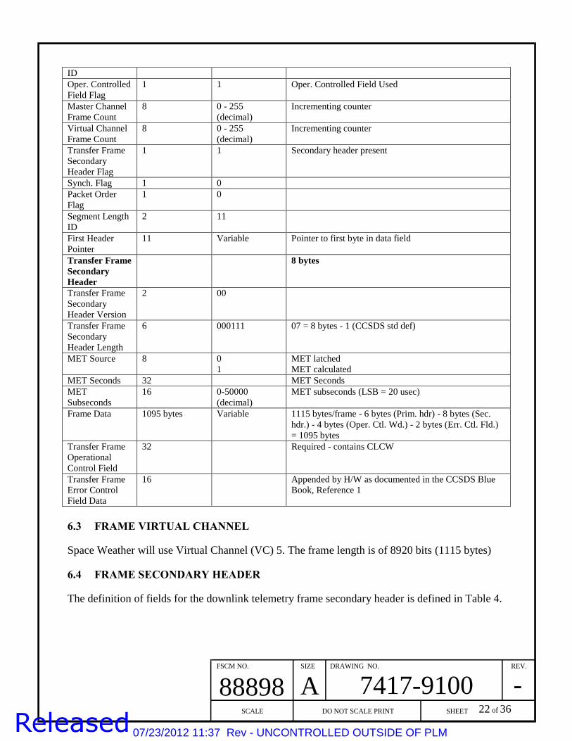
Table 4: Telemetry Frame Contents
Bit Field Length (bits) Value
(binary)
Description
Transfer Frame
Primary
Header
6 bytes
Transfer Frame
Version No
2 00
Spacecraft ID 10 0101101010 or
0101101011
RBSP ID (0x16A OR 0x16B)
Virtual Channel 3 101 VC05 for 8920 bit space weather
PRIMARY
HEADER
(6 bytes)
FRAME DATA
(up to 1095
bytes)
OPERATIONAL
CONTORL
(4 bytes)
TELEMETRY TRANSFER FRAME
VERSION
NUMBER
(2 bits)
MASTER
FRM CNT
(8 bits)
VC
FRAME CNT
(8 bits)
OPERAT’NL
CTL FLAG
(1 bit)
S/C
ID
(10 bits)
VIRTUAL
CHANNEL
(3 bits)
SEC HDR
FLAG
(1 bit)
SYNC
FLAG
(1 bit)
PRIMARY HEADER
PKT ORDER
FLAG
(1 bit)
SEGMENT
LENGTH ID
(2 bits)
FIRST HDR
OFFSET
(11 bits)
FRAME ERROR
CONTROL
(2 bytes)
SECONDARY
HEADER
(8 bytes)
VERSION
NUMBER
(2 bits)
SEC HDR
LENGTH
(6 bits)
MET
(6 bytes)
SECONDARY HEADER
07/23/2012 11:37 Rev - UNCONTROLLED OUTSIDE OF PLM
FSCM NO. SIZE DRAWING NO. REV.
SCALE DO NOT SCALE PRINT SHEET
88898 A 7417-9100 -
22 of 36
ID
Oper. Controlled
Field Flag
1 1 Oper. Controlled Field Used
Master Channel
Frame Count
8 0 - 255
(decimal)
Incrementing counter
Virtual Channel
Frame Count
8 0 - 255
(decimal)
Incrementing counter
Transfer Frame
Secondary
Header Flag
1 1
Secondary header present
Synch. Flag 1 0
Packet Order
Flag
1 0
Segment Length
ID
2 11
First Header
Pointer
11 Variable Pointer to first byte in data field
Transfer Frame
Secondary
Header
8 bytes
Transfer Frame
Secondary
Header Version
2 00
Transfer Frame
Secondary
Header Length
6 000111 07 = 8 bytes - 1 (CCSDS std def)
MET Source 8 0
1
MET latched
MET calculated
MET Seconds 32 MET Seconds
MET
Subseconds
16 0-50000
(decimal)
MET subseconds (LSB = 20 usec)
Frame Data 1095 bytes Variable 1115 bytes/frame - 6 bytes (Prim. hdr) - 8 bytes (Sec.
hdr.) - 4 bytes (Oper. Ctl. Wd.) - 2 bytes (Err. Ctl. Fld.)
= 1095 bytes
Transfer Frame
Operational
Control Field
32 Required - contains CLCW
Transfer Frame
Error Control
Field Data
16 Appended by H/W as documented in the CCSDS Blue
Book, Reference 1
6.3 FRAME VIRTUAL CHANNEL
Space Weather will use Virtual Channel (VC) 5. The frame length is of 8920 bits (1115 bytes)
6.4 FRAME SECONDARY HEADER
The definition of fields for the downlink telemetry frame secondary header is defined in Table 4.
07/23/2012 11:37 Rev - UNCONTROLLED OUTSIDE OF PLM

FSCM NO. SIZE DRAWING NO. REV.
SCALE DO NOT SCALE PRINT SHEET
88898 A 7417-9100 -
23 of 36
7 SPACE WEATHER PACKET DEFINITIONS
Tables 6-17 containing details for each APID in Table 1 are provided here
7.1 EMFISIS SPACE WEATHER DATA
Table 6. EMFISIS Space Weather Packet (APID 0x28C)
Field Description Start
Bit
Size
(bits) Note
CCSDS Version 0 3 Value is always zero (0) Pkt Type 3 1 0=telemetry Sec. Hdr. Flag 4 1 1=has secondary header Application ID 5 11 EMFISIS APID
Grouping Flags 16 2 CCSDS definition of grouping
flags: 3 – not part of group
Sequence Count 18 14 Increments with each new packet.
Value is 0 - 16383
Packet Length 32 16 Data size, number of bytes
following the “Packet Length”
minus 1, (value is always ODD)
MET Seconds 48 32 Packet Time (sec). Value is 0 -
4294967295
MET SubSeconds 80 16 50 microseconds/tic. Value is 0 -
19999
Spin Phase at 1 PPS 96 16 Spin Phase @ 1 PPS from Time and
Status Messages
MET of Spin Phase 1 PPS 112 16
Low 16 bits of MET from the 1 PPS
associated with the Spin Phase in
the Time and Status Message
Magnetometer Calibration Signal State 128 1 0=off, 1=on
Magnetometer Range 129 2
00: 256 nT
01: 4096 nT
10: not used
11: 65536 nT
Spare 131 13
Mag X Component 144 16
Mag Y Component 160 16
Mag Z Component 176 16
Waves Parameter 1 192 16
Waves Parameter 2 208 16
Waves Parameter 3 224 16
Waves Parameter 4 240 16
Waves Parameter 5 256 16
Waves Parameter 6 272 16
07/23/2012 11:37 Rev - UNCONTROLLED OUTSIDE OF PLM

FSCM NO. SIZE DRAWING NO. REV.
SCALE DO NOT SCALE PRINT SHEET
88898 A 7417-9100 -
24 of 36
7.2 EFW SPACE WEATHER DATA
Table 7. EFW Space Weather Packet (APID 0x26A) Description Start
Bit
Size
(bits)
Mnemonic
CCSDS Version 0 3 Value is always zero (0)
Pkt Type 3 1 0=telemetry
Sec. Hdr. Flag 4 1 1=has secondary header
Application ID 5 11 EFW APID
Grouping Flags 16 2 CCSDS definition of grouping
flags:3 – not part of group
Sequence Count 18 14 Increments with each new packet
Packet Length 32 16
Data size, number of bytes
following the “Packet Length”
minus 1, (value is always ODD)
MET Seconds 48 32 Packet Time (sec)
Shared Status 80 8 (ISDM0)
80 4 TBD (ISDM0)
Sweep State [0..3] = Off, V12, V34, V56
sweeping
84 2 SWEEP_STATE (ISDM0)
AXB Aft Illumination Mode 86 2 AFT_ILLUM (ISDM0)
Requested Burst Support Bits 88 8 EXT_SUPPORT_REQ
Configuration and Evaluation Function 96 8 EXT_STATUS FUNC
Value Calculated by Evaluation Function 104 8 EXT_STATUS_VAL
Spacecraft Potential = AVG (0.5*(V1+V2)) 112 16 SC_POTENTIAL
Vector E-Field Offset A 128 24 Ex_OFFSET
Vector E-Field Cosine Term B 152 24 Ex_COSINE
Vector E-Field Sine Term C 176 24 Ex_SINE
Vector E-Field Standard Deviation of the
Fit
200 24 Ex_STDDEV
Used to make quad word length 224 0 Spare
7.3 ECT/HOPE SPACE WEATHER DATA
Table 8. ECT/HOPE Space Weather Packet for ions (APID 0x22C) Description Start bit Size
(bits)
Notes
CCSDS Version (always 0) 0 3
CCSDS Packet Type (0=telemetry) 3 1
Has secondary header (always 1) 4 1
Application ID 5 11
Packet grouping flags 16 2 0=intermediate, 1=first, 2=last, 3=no group
Packet Sequence Counter 18 14
Packet Length 32 16 Packet Length: Number of bytes following
this field - 1
Mission Elapsed Time 48 32
Whole second start of HOPE Spin (sec) 80 8
Subsecond start of HOPE Spin (msec) 88 16
Whether STARTs are included 104 1 Denotes whether start counts are included in
the data product. 0=No, 1=Yes
07/23/2012 11:37 Rev - UNCONTROLLED OUTSIDE OF PLM
FSCM NO. SIZE DRAWING NO. REV.
SCALE DO NOT SCALE PRINT SHEET
88898 A 7417-9100 -
25 of 36
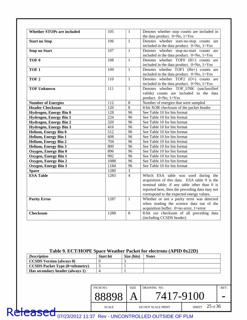
Whether STOPs are included 105 1 Denotes whether stop counts are included in
the data product. 0=No, 1=Yes
Start no Stop 106 1 Denotes whether start-no-stop counts are
included in the data product. 0=No, 1=Yes
Stop no Start 107 1 Denotes whether stop-no-start counts are
included in the data product. 0=No, 1=Yes
TOF 0 108 1 Denotes whether TOF0 (H+) counts are
included in the data product. 0=No, 1=Yes
TOF 1 109 1 Denotes whether TOF1 (He+) counts are
included in the data product. 0=No, 1=Yes
TOF 2 110 1 Denotes whether TOF2 (O+) counts are
included in the data product. 0=No, 1=Yes
TOF Unknown 111 1 Denotes whether TOF_UNK (unclassified
valids) counts are included in the data
product. 0=No, 1=Yes
Number of Energies 112 8 Number of energies that were sampled
Header Checksum 120 8 8-bit XOR checksum of the packet header
Hydrogen, Energy Bin 0 128 96 See Table 10 for bin format
Hydrogen, Energy Bin 1 224 96 See Table 10 for bin format
Hydrogen, Energy Bin 2 320 96 See Table 10 for bin format
Hydrogen, Energy Bin 3 416 96 See Table 10 for bin format
Helium, Energy Bin 0 512 96 See Table 10 for bin format
Helium, Energy Bin 1 608 96 See Table 10 for bin format
Helium, Energy Bin 2 704 96 See Table 10 for bin format
Helium, Energy Bin 3 800 96 See Table 10 for bin format
Oxygen, Energy Bin 0 896 96 See Table 10 for bin format
Oxygen, Energy Bin 1 992 96 See Table 10 for bin format
Oxygen, Energy Bin 2 1088 96 See Table 10 for bin format
Oxygen, Energy Bin 3 1184 96 See Table 10 for bin format
Spare 1280 3
ESA Table 1283 4 Which ESA table was used during the
acquisition of this data. ESA table 0 is the
nominal table; if any table other than 0 is
reported here, then the preceding data may not
correspond to the expected energy values.
Parity Error 1287 1 Whether or not a parity error was detected
when reading the science data out of the
acquisition buffer. 0=no error, 1=error
Checksum 1288 8 8-bit xor checksum of all preceding data
(including CCSDS header)
Table 9. ECT/HOPE Space Weather Packet for electrons (APID 0x22D) Description Start bit Size (bits) Notes
CCSDS Version (always 0) 0 3
CCSDS Packet Type (0=telemetry) 3 1
Has secondary header (always 1) 4 1
07/23/2012 11:37 Rev - UNCONTROLLED OUTSIDE OF PLM
FSCM NO. SIZE DRAWING NO. REV.
SCALE DO NOT SCALE PRINT SHEET
88898 A 7417-9100 -
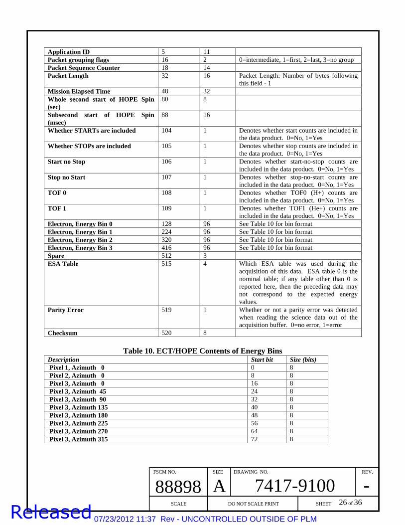
26 of 36
Application ID 5 11
Packet grouping flags 16 2 0=intermediate, 1=first, 2=last, 3=no group
Packet Sequence Counter 18 14
Packet Length 32 16 Packet Length: Number of bytes following
this field - 1
Mission Elapsed Time 48 32
Whole second start of HOPE Spin
(sec)
80 8
Subsecond start of HOPE Spin
(msec)
88 16
Whether STARTs are included 104 1 Denotes whether start counts are included in
the data product. 0=No, 1=Yes
Whether STOPs are included 105 1 Denotes whether stop counts are included in
the data product. 0=No, 1=Yes
Start no Stop 106 1 Denotes whether start-no-stop counts are
included in the data product. 0=No, 1=Yes
Stop no Start 107 1 Denotes whether stop-no-start counts are
included in the data product. 0=No, 1=Yes
TOF 0 108 1 Denotes whether TOF0 (H+) counts are
included in the data product. 0=No, 1=Yes
TOF 1 109 1 Denotes whether TOF1 (He+) counts are
included in the data product. 0=No, 1=Yes
Electron, Energy Bin 0 128 96 See Table 10 for bin format
Electron, Energy Bin 1 224 96 See Table 10 for bin format
Electron, Energy Bin 2 320 96 See Table 10 for bin format
Electron, Energy Bin 3 416 96 See Table 10 for bin format
Spare 512 3
ESA Table 515 4 Which ESA table was used during the
acquisition of this data. ESA table 0 is the
nominal table; if any table other than 0 is
reported here, then the preceding data may
not correspond to the expected energy
values.
Parity Error 519 1 Whether or not a parity error was detected
when reading the science data out of the
acquisition buffer. 0=no error, 1=error
Checksum 520 8
Table 10. ECT/HOPE Contents of Energy Bins Description Start bit Size (bits)
Pixel 1, Azimuth 0 0 8
Pixel 2, Azimuth 0 8 8
Pixel 3, Azimuth 0 16 8
Pixel 3, Azimuth 45 24 8
Pixel 3, Azimuth 90 32 8
Pixel 3, Azimuth 135 40 8
Pixel 3, Azimuth 180 48 8
Pixel 3, Azimuth 225 56 8
Pixel 3, Azimuth 270 64 8
Pixel 3, Azimuth 315 72 8
07/23/2012 11:37 Rev - UNCONTROLLED OUTSIDE OF PLM

FSCM NO. SIZE DRAWING NO. REV.
SCALE DO NOT SCALE PRINT SHEET
88898 A 7417-9100 -
27 of 36
Pixel 4, Azimuth 0 80 8
Pixel 5, Azimuth 0 88 8
7.4 ECT/MAGEIS SPACE WEATHER DATA
Space Weather data is output from three of the MagEIS instruments. The Low instrument,
Med75, and High instrument will generate Space Weather packets. The Med35 will not generate
Space Weather but will retain the capability to do so in the flight software. The output is
compressed from 24 to 10 bits. Each data packet will be output once per spin and will contain
data for 8 spin sectors. The cadence for Space Weather can be set by a Parameter command.
The MagEIS Space Weather format for the Low, Med75 and Med35 instruments is shown in the
table 11. The data following the header consists of 4 bytes corresponding to three 10-bit space-
weather words packed together in order from lowest energy channel to highest energy channel
and then followed by two zeros. Each 4-byte set corresponds to one sector starting from the first
sector following the spin boundary. Note (red asterisk below) that the data is compressed into 4
packed bytes per sector. The last two bits of each sector are padded zero and should be ignored.
Table 11. ECT/MagEIS Space Weather Packet for Low (APID 0x34A), Medium 35
(0x35A), and Medium 75 (APID 0x36A) (electrons)
Field Description Start bit
Size
(bits) Note
CCSDS Version 0 3 Value is always zero
Packet Type 3 1 0 = telemetry
Secondary Header Flag 4 1 1 = has secondary header
APID 5 11
APID is value plus offset based on MAGEIS' allocated
APID range
Grouping Flags 16 2 3 = not part of group
Sequence Count 18 14 Increments with each new packet
Packet Length 32 16 Data size, number of bytes following the "Packet
Length" minus 1, (value is always ODD)
MET seconds 48 32 Spin time in MET
MAGEIS fine time 80 16 fine time (ms) from MET
e-Space Weather Data* 96 256 Sector -> Channel -> 10 bits
The MagEIS High instrument contains two Space Weather packets: one for Electrons and one
for Protons. The Electron Packet is shown in Table 12. The packing of the electron data is
different for the High than the Low and Medium instruments. In the High instrument, there is
only one electron channel and the 10-bit data items are output sequentially for each sector,
starting from the first sector after the spin boundary. This requires exactly 10 bytes for the entire
spin’s worth of data, so there is no zero fill. The Proton Packet is shown in Table 13. The
packing of proton data is identical as the electron data in the High instrument.
07/23/2012 11:37 Rev - UNCONTROLLED OUTSIDE OF PLM

FSCM NO. SIZE DRAWING NO. REV.
SCALE DO NOT SCALE PRINT SHEET
88898 A 7417-9100 -
28 of 36
Table 12. ECT/MagEIS Space Weather Packet for High (electrons) (APID 0x375)
Field Description Start bit
Size
(bits) Note
CCSDS Version 0 3 Value is always zero
Packet Type 3 1 0 = telemetry
Secondary Header Flag 4 1 1 = has secondary header
APID 5 11
APID is value plus offset based on MAGEIS' allocated
APID range
Grouping Flags 16 2 3 = not part of group
Sequence Count 18 14 Increments with each new packet
Packet Length 32 16 Data size, number of bytes following the "Packet
Length" minus 1, (value is always ODD)
MET seconds 48 32 Spin time in MET
MAGEIS fine time 80 16 fine time (ms) from MET
e-Space Weather Data* 96 80 Sector -> Channel -> 10 bits
Table 13. ECT/MagEIS Space Weather Packet for High (protons) (APID 0x382)
Field Description Start bit Size (bits) Note
CCSDS Version 0 3 Value is always zero
Packet Type 3 1 0 = telemetry
Secondary Header Flag 4 1 1 = has secondary header
APID 5 11
APID is value plus offset based on MAGEIS'
allocated APID range
Grouping Flags 16 2 3 = not part of group
Sequence Count 18 14 Increments with each new packet
Packet Length 32 16 Data size, number of bytes following the "Packet
Length" minus 1, (value is always ODD)
MET seconds 48 32 Spin time in MET
MAGEIS fine time 80 16 fine time (ms) from MET
e-Space Weather Data* 96 80 Sector -> Channel -> 10 bits
The MagEIS Space Weather data is compressed from 24 bits to 10 bits. The conversion is
shown in table 14.
Table 14. ECT/MagEIS Compression Data (applies to all MagEIS instruments) Compression
#
Compression
Name Compression Type Bits Conversion Units
1 24 bits to 10 bits 5 bit Exponent followed by 5 bit Significand 10 S x 2^E counts
7.5 ECT/REPT SPACE WEATHER DATA
Table 15. ECT/REPT Space Weather Packet (APID 0x201) Field Name Start Bit Size (bits) Description
CCSDS Version 0 3 Value always 0
07/23/2012 11:37 Rev - UNCONTROLLED OUTSIDE OF PLM

FSCM NO. SIZE DRAWING NO. REV.
SCALE DO NOT SCALE PRINT SHEET
88898 A 7417-9100 -
29 of 36
Packet Type 3 1 0 = telemetry
Sec. Hdr. Flag 4 1 1 = secondary header included
Application ID 5 11 0x200 – 0x20A = indicates type of packet
Grouping Flags 16 2 3 = Not part of group
Sequence Count 18 14 Increments with each packet
Packet Length 32 16 Size of data and secondary header minus 1
MET Seconds 48 32 Time of packet transmission
Singles Counter 2 80 12
Singles Counter 4 92 12
Singles Counter 9 104 12
REPT_INST_ID 116 2
Pad 118 10
Checksum 128 16
7.6 RBSPICE SPACE WEATHER DATA
Table 16. RBSPICE Space Weather Packet (APID 0x311) Name Start bit Length (bits) Description
Version 0 3 Designates a source packet
Type 3 1 Designates a telemetry packet
Secondary? 4 1 Secondary header is present
APID 5 11 Application Process ID
Grouping 16 2 Grouping flags
Sequence Count 18 14 Continuous sequence count for each Application
Process ID
Length 32 16 Packet length (bytes) – 1
Secondary Header 48 32 Time tag (MET)
Spin 80 16 Spin number of integration
No. Fast 96 8 Number of fast values (NF)
No. Slow 104 8 Number of slow values (NS)
Fast 0 Chans –
45KeV
112 NF * 10 Low energy, high-time resolution space weather
rates. There are 4*NF values where NF = 36
Fast 1 Chans –
100KeV
472 NF * 10 Low energy, high-time resolution space weather
rates. There are 4*NF values where NF = 36
Fast 0 Chans – 148
KeV
832 NF * 10 Low energy, high-time resolution space weather
rates. There are 4*NF values where NF = 36
Fast 0 Chans – 269
KeV
1192 NF * 10 Low energy, high-time resolution space weather
rates. There are 4*NF values where NF = 36
Slow 0 Chans – 1
MeV(TBR)
1552 NS * 10 High energy, low-time resolution space weather
rates. There are 2*NS values where NS = 4
Slow 1 Chans - 10
MeV(TBR)
1592 NS * 10 High energy, low-time resolution space weather
rates. There are 2*NS values where NS = 4
Pad 1632 0 - 15 Zero pad to 16-bit boundary
07/23/2012 11:37 Rev - UNCONTROLLED OUTSIDE OF PLM

FSCM NO. SIZE DRAWING NO. REV.
SCALE DO NOT SCALE PRINT SHEET
88898 A 7417-9100 -
30 of 36
7.7 PSBR/RPS SPACE WEATHER DATA
Table 17. PSBR/RPS Rate & Housekeeping Packet (& Space Weather) (APID 0x2C1) Description Start bit Size bit
CCSDS Version = 0 0 3
Packet Type = 0 (telemetry) 3 1
Secondary Header Flag = 1 (set) 4 1
Application ID = 0x2C1 5 11
Grouping Flags = 3 (not part of group) 16 2
Sequence Count (increment with each output packet) 18 14
Packet Length = 31 32 16
MET Seconds = packet time 48 32
PEN rate 80 16
CHE rate 96 16
Various RPS Housekeeping Data 112 160
Spare (Dosimeter1 linear mon.) * 272 8
Spare (Dosimeter1 log mon.) *
Spare (Dosimeter2 linear mon.) *
Spare (Dosimeter2 log mon.) *
RPS Housekeeping Data. 280 8
Spare = 0xA5 288 8
Checksum 296 8
* The dosimeter data is multiplexed over 4 packets
07/23/2012 11:37 Rev - UNCONTROLLED OUTSIDE OF PLM

FSCM NO. SIZE DRAWING NO. REV.
SCALE DO NOT SCALE PRINT SHEET
88898 A 7417-9100 -
31 of 36
8 PREDICTED EPHEMERIS FILES
The predicted ephemeris files will be available from the RBSP MOC 60 days in advance. The
details of this file are given below in Table 18:
Table 18: Predicted Ephemeris
Name Ephermeris Prediction
File Name scid_yyyy_doy_##.peph.bsp; peph_scid_yyyy_doy_##.peph.xsp (where
yyyy_doy is the first date in the file)
Originator Navigation
User MOC, Ground Stations, TDRSS, SOC, SDP
Transfer
Protocol
sftp from MOC Data Server
Availability 1-2 times per week
Frequency 1-2 times per week
Initiation Automatic
Action Generate, Store
Format SPICE Planetary Ephemerides Kernel (SPK), binary (nominal) (bsp) and
transfer (xsp) formats
Contents Position and velocity of each spacecraft as a function of time. Will likely be
Earth-centered inertial vectors (i.e. vectors expressed in EME2000 reference
frame) SPICELIB tools allow querying for vectors in many other coordinate
systems. Data extrapolated for 60 days.
Purpose To predict where the two satellites will be in the future
07/23/2012 11:37 Rev - UNCONTROLLED OUTSIDE OF PLM

FSCM NO. SIZE DRAWING NO. REV.
SCALE DO NOT SCALE PRINT SHEET
88898 A 7417-9100 -
32 of 36
9 SPACE ASSET PROTECTION POLICY IMPLICATIONS
Space asset protection policy will have an impact on RBSP space weather data. The spacecraft
position information (which must be provided to other ground stations to receive the data) will
need to have a control process (e.g. signed MOU with other organizations to restrict access to
this data). Making the agreements with the ground station providers is the responsibility of
NASA HQ.
The space weather measurements made on the spacecraft will have to be combined (by the user
of the data) with spacecraft position in order to be useful. It is expected that the data users will
download the predicted spacecraft ephemeris files for this purpose. Since the predict file will be
produced 60 days in advance, this information will have some uncertainties, but will be
sufficiently accurate for scientific purposes. For the real-time broadcast, the complete spacecraft
tracking information will be provided to the participating ground stations who will use this
information to track the spacecraft.
07/23/2012 11:37 Rev - UNCONTROLLED OUTSIDE OF PLM

FSCM NO. SIZE DRAWING NO. REV.
SCALE DO NOT SCALE PRINT SHEET
88898 A 7417-9100 -
33 of 36
10 INSTITUTIONAL RESPONSIBILITIES
10.1 RADIATION BELT STORM PROBES MISSION
The responsibility of the RBSP Mission is to broadcast the selected space weather data at all
times through the primary spacecraft science downlink antennas when an observatory is not in a
primary mission-related ground contact. It is a goal for the instrument SOCs to provide a space
weather product from their prime science data within a few days to compensate for any data gaps
due to unavailability of observatory or poor orbit geometry.
10.2 NASA PROGRAM OFFICE
The responsibility of the program office at NASA headquarters is to recruit ground stations to
participate in receiving and relaying RBSP Space Weather Broadcast data consonant with the
arrangements described above. NASA HQ also provides the programmatic interface between the
users and the RBSP Project.
10.3 GROUND STATION PARTNERS
The responsibility of each ground station will be the subject of an agreement between NASA and
the ground station operator. The Space Weather data customer is responsible for working with
their selected ground station to maintain the RF link analyses, including the determination of
receiver loop bandwidth settings based on orbit geometry and carrier tracking requirements.
07/23/2012 11:37 Rev - UNCONTROLLED OUTSIDE OF PLM

FSCM NO. SIZE DRAWING NO. REV.
SCALE DO NOT SCALE PRINT SHEET
88898 A 7417-9100 -
34 of 36
11 COMMUNICATION BETWEEN RBSP AND THE PARTICIPATING GROUND
STATIONS
Technical communications between the RBSP mission and the participating ground station
partners will be by email and telephone during normal business hours.
The RBSP Mission Operations Center (MOC) is designed to operate without human interaction.
MOC personnel will only be available on a regular basis during normal business hours. The
MOC will supply the ground station partners with contact information, in case of problems,
which will be addressed as rapidly as feasible.
07/23/2012 11:37 Rev - UNCONTROLLED OUTSIDE OF PLM

FSCM NO. SIZE DRAWING NO. REV.
SCALE DO NOT SCALE PRINT SHEET
88898 A 7417-9100 -
35 of 36
APPENDIX A: ACRONYMS
ACE Advanced Composition Explorer
APID Application Identifier (in a CCSDS telemetry packet header)
C&DH Command and Data Handling
CCSDS Consultative Committee for Space Data Systems
CHE 1-second coincidence rates as fluxes >400 ~MeV protons
CLCW Command Link Control Word
ECT Energetic Particle Composition and Thermal Plasma Investigation
EFW Electric Field and Waves Instrument
EMFISIS Electric and Magnetic Field Instrument Suite and Integrated Science
Investigation
GSFC Goddard Space Flight Center
HOPE Helium-Oxygen-Proton-Electron Spectrometer Instrument
ICD Interface Control Document
JHU/APL Johns Hopkins University Applied Physics Laboratory
LEO Low Earth Orbit
LWS Living With a Star
MagEIS Magnetic Electron Ion Spectrometer
MEO Medium Earth Orbit
MET Mission Elapsed Time
MOU Memorandum of Understanding
MOC Mission Operation Center
MRD Mission Requirements Document
NASA National Aeronautics and Space Administration
PEN 1-second coincidence rates as fluxes >50 ~MeV protons
PSBR Proton Spectrometer Belt Research
RBSP Radiation Belt Storm Probes
RBSPICE Radiation Belt Storm Probes Ion Composition Experiment
REPT Relativistic Electron Proton Telescope Instrument
07/23/2012 11:37 Rev - UNCONTROLLED OUTSIDE OF PLM
FSCM NO. SIZE DRAWING NO. REV.
SCALE DO NOT SCALE PRINT SHEET
88898 A 7417-9100 -
36 of 36
RPS Relativistic Proton Spectrometer Instrument
RF Radio Frequency
SDMP Science Data Management Plan
SOC Science Operation Center
SSPA Solid State Power Amplifier
STARD Science Team Allocated Requirements Document
STEREO Solar TErrestrial RElations Observatory
TBD To Be Determined
TBR To Be Revised
UTC Universal Time Coordinated
VC Virtual Channel
07/23/2012 11:37 Rev - UNCONTROLLED OUTSIDE OF PLM